Embed Size (px)
Citation preview

Owners Manual & Operating Instructions
MAG65702INST
Magnum Bolt Buster Drill Rig - PN MAG65702
Bolt Buster657

GENERAL SAFETY RULES FOR ALL POWER TOOLSWork Area
• KEEP WORK AREA CLEAN - Cluttered areas and benches invite accidents.
• AVOID DANGEROUS ENVIRONMENTS - Don’t use power tools in damp or wet locations. Do not expose power tools to rain. Keep work area well lit.
• AVOID GASEOUS AREAS - Do not operate portable electric tools in explosive atmospheres in presence of flammable liquids or gases. Motors in these tools normally spark, and the sparks might ignite fumes.
• KEEP CHILDREN AWAY - Do not let visitors contact tool or extension cord. All visitors should be kept away from work areas.
Personal Safety• GUARD AGAINST ELECTRIC SHOCK - Prevent body contact with grounded surfaces such
as pipes, radiators, ranges and refrigerator enclosures. Rubber gloves and non-skid footwear are recommended when working outdoors, where damp or wet ground may be encountered. A Ground Fault Circuit Interrupter protected power line must be used for these conditions.
• DRESS PROPERLY - Do not wear loose clothing or jewelry. They can be caught in moving parts. Wear protective hair covering to contain long hair.
• USE SAFETY EQUIPMENT - WEAR SAFETY GOGGLES or glasses with side shields. Wear hearing protection during extended use of power tools and dust mask for dusty operations.
• STAY ALERT. USE COMMON SENSE - Watch what you are doing. Do not operate tool when you are tired or under influence of drugs.
• REMOVE ADJUSTING KEYS AND WRENCHES - Form habit of checking to see that keys and adjusting wrenches are removed from tool before turning it on.
• AVOID ACCIDENTAL STARTING - Don’t carry plugged in tool with finger on switch. Be sure the switch is OFF before being plugged in.
• DON’T OVERREACH - Keep proper footing and balance at all times.
• BEFORE CONNECTING THE TOOL to a power supply (receptacle, outlet, etc.) be sure the voltage supplied is the same as that specified on the tool’s nameplate. A power supply with voltage greater than that specified for the tool can result in serious injury to the user - as well as damage to the tool. If in doubt, DO NOT PLUG IN THE TOOL. Using a power supply with voltage less than the nameplate rating is harmful to the motor.
NOTE: “Volts AC” designated tools are for Alternating Current 50-60 Hz only. “Volts DC” designated tools are for Direct Current. Do not use AC designated tools with DC power supply. Do not use electronic speed controlled tools with DC power supply.
1

TOOL USE AND CARE• DON’T FORCE TOOL - It will do the job better and safer at the rate for which it was designed.
• USE RIGHT TOOL - Don’t force small tool or attachment to do the job of a heavy-duty tool. Don’t use tool for purpose not intended - for example; don’t use a circular saw for cutting tree limbs or logs.
• SECURE WORK - Use clamps or a vise to hold work. It’s safer than using your hand and it frees both hands to operate the tool.
• DON’T ABUSE CORD - Never carry tool by cord or yank it to disconnect from receptacle. Keep cord from heat, oil, and sharp edges. Always keep cord away from the spinning blade, bits or any other moving part while the tool is in use.
• OUTDOOR USE EXTENSION CORDS - When tool is used outdoors, use only extension cords suitable for use outdoors and marked with suffix W-A (for UL), or W (for CSA).
• DISCONNECT TOOLS - When not in use, before servicing, or when changing blades, bits, cutters, etc.
• STORE IDLE TOOLS - When not in use, tools should be stored in dry, high or locked up place - out of the reach of children.
• DO NOT ALTER OR MISUSE TOOL - These tools are precision built. Any alterations or modifications not specified is misuse and may result in a dangerous condition.
• THE USE OF ANY ACCESSORIES - not specified in this manual may create a hazard.
• MAINTAIN TOOLS WITH CARE - Keep tools sharp and clean for better and safer perfor-mance. Follow instructions for lubricating and changing accessories. Inspect tool cords peri-odically and if damaged, have repaired by authorized service facility. Inspect extension cords periodically and replace if damaged. Keep handles dry, clean and free from oil and grease.
• CHECK DAMAGED PARTS - Before further use of the tool, a guard or other part that is damaged should be carefully checked to determine that it will operate properly and perform its intended function. Check for alignment of moving parts, binding of moving parts, breakage of parts, mounting, and any other conditions that may affect its operation. A guard or other part that is damaged should be promptly and properly repaired or replaced. Have defective switches replaced. Do not use tool if switch does not turn it on or off.
• ALL REPAIRS, ELECTRICAL OR MECHANICAL should be attempted only by trained repair-men.
2

A - Hole Saw Drill Rig MAG65702
B - (1) J-Hook L2021S02
C - (1) High Speed Drill Bit BRUTE1/2
D - (10pk) Mounting Screws MAG657SCREW
E - (1) 7/16” Drive Shaft Adapter MAG657ADAPT
F - (1) 5/16” Nut Driver MAG657DRIVER
G - Die Cut Foam (Not pictured) MAG65702FOAM
H - (1) Alpha Class 6 Magnetic Template GSAA6TMP
I - (1) Hamilton Class 6 Magnetic Template GSAH6TMP
J - (1) Mosler Class 6 Magnetic Template GSAM6TMP
K - (2) 2” Carbide Hole Saw LKMLNX2CT
L - (1) 1/2” Arbor LKMLNX300022L
M - Chuck Key
N - Heavy Duty Carrying Case (Not pictured) MAG65702CASE
O - Instructions (Not pictured) MAG65702INST
P - Hex Wrench
Q - (2) Clean-out Screws
3
KIT INCLUDES
A
B
C
H
I
D
E
F
J
KL
M
P
Q

4
Hamilton Class 6 Legal SizePart Number Description
CL6DHBH Control Drawer Only - No Lock, Black
CL6DHGH Control Drawer Only - No Lock, Gray
CL6DHPH Control Drawer Only - No Lock, Parchment
Alpha Class 6 Legal SizePart Number Description
ALTCDHNLWB Control Drawer Only - No Lock, Black
ALTCDHNLWG Control Drawer Only - No Lock, Gray
ALTCDHNLWP Control Drawer Only - No Lock, Parchment
Mosler/Diebold Class 6 Legal SizePart Number Description
* CL6DHBM Control Drawer Only - No Lock, Black
* CL6DHGM Control Drawer Only - No Lock, Gray
* CL6DHPM Control Drawer Only - No Lock, Parchment
* Manufactured by Hamilton ProductsAll Drawer Heads can be supplied with a lock meeting FF-L-2740
REPLACEMENT DRAWER HEAD PART NUMBERS

5
MAGNUM BOLT BUSTERTheMagnumBoltBusterRigwasspecificallydesignedfortheapprovedopeningofHam-ilton,Mosler-Diebold,andAlphaGSAapprovedClass6,redlabel,filecabinetsbycuttingthe lock bolts. The Magnum Bolt Buster Rig should not be used for opening Class 5 Containers, Vault doors, Map and plan containers, non-GSA approved containers or black label containers unless they are to be scrapped. Black label GSA containers do not have replaceable drawer heads. Once the bolts have been cut, the drawer head will need to be replaced. Replacement drawer heads are available through Lockmasters. See the back page for Part Numbers.
TheBoltBusterRigwasdesignedfromthegrounduptocutthelockingboltsonGSAfilecabinets. It absorbs the chatter, vibration and force that is required to cut through the lock-ing bolts. The rig, combined with the high torque low speed drill motor (400 RPM, 10 Amp), suchastheMakitaDS4000drill,providesandthecuttingefficiencyoftheLennox2”Car-bide Hole Saws will make quick work of opening control drawers. The Bolt Buster assembly completely encloses the hole saw keeping most of the debris and sparks contained inside the cabinet, cutting down on the need for burn permits which are required in certain areas when this method is used.
The Bolt Buster makes this method a safer alternative than using a hole saw and drill by hand. A special J-Hook is supplied with the rig to keep the locking bolt from pinching as the hole saw cuts through. This method will also prolong the life of the carbide hole saws.
Using this method will save the combination lock, Combination Locks meeting FF-L-2740 are more expensive than a replacement drawer. After the drawer is open, the lock can reset to a known combination, or be repaired depending on the vintage of the combination lock.
* This video does not replace the written instructions. Please continue to refer back
to the written instructions for use.
Scan to view the Magnum Bolt Buster Instructional Video.

For Hamilton Legal Size: Topofdrawerdown-51/8”todeterminethecenterlineofthelockingbolts. Leftsideedgeofdrawerinwards23/4”fortheJ-Hook,53/8”inwardforholesawlocation. Rightsideedgeofdrawerinwards23/4”fortheJ-Hook,53/8”forholesawlocation.
MAGNUM BOLT BUSTER
2 34 "
4 34 "
5 38 "5 3
8 "
12 "
12 "
2 34 " 2 3
4 "
5 18 "
NOT SHOWN TO SCALE
HAMILTON CLASS 6 HOLE SAW DRILL POINT
LAYOUT
Rev. 7-18MAG65702HAM
6
Align the magnetic template supplied with the kit on the container. The templates are labeled at the top for Hamilton, Mosler -Diebold, Alpha Class 6. These templates are designed for legal size drawers.
NOTE: Magnetic Templates were not used for these instructions. If templates are not available, you can measure down and from the side inward to determine the proper drill locations.
These Templates will give you an X-Ray view of the internals of the control drawer. For Drill Rig placement, use the dimensions printed in the instructions.
Note: Before continuing, see back page for a useful tip.

7
MAGNUM BOLT BUSTER
6 34 "
4 2132 "
3 38 "
6 14 "
3 516 "
5 34 "
12 "
12 "
3 532 " 3 5
32 "
5 1116 "
DIEBOLD CLASS 6 HOLE SAW DRILL POINT
LAYOUT
NOT SHOWN TO SCALE Rev. 6-13MAG65702DIE
4 78 "
2 2332 "
4 34 "
2 2332 "
4 34 "
5 34 "
5 332 "
12 "
2 78 " 1 3
4 "
Rev. 6-13NOT SHOWN TO SCALEMAG65702AL
ALPHA CLASS 6 HOLE SAW DRILL POINT
LAYOUT
For Alpha Legal Size: Topofdrawerdown-53/32”todeterminethecenterlineofthelockingbolts. Leftsideedgeofdrawerinwards27/8”fortheJ-Hook,53/4”inwardforholesawlocation. Rightsideedgeofdrawerinwards13/4”fortheJ-Hook,47/8”forholesawlocation.
For Diebold-Mosler Legal Size: Topofdrawerdown-511/16”todeterminethecenterlineofthelockingbolts. Rightsideedgeofdrawerinwards35/32”fortheJ-Hook,61/4”inwardfortheholesawlocation. Leftsideedgeofdrawerinwards35/32”fortheJ-Hook,63/4”forthetopdrillrighole,53/4 for the bottom drill rig hole. (This is done so the drill rig does not interfere with the handle.)

Center the drill rig vertically and horizontally over the center line of each locking bolt making sure the2”holesawwillcutevenlythrougheachbolt.
Once in position, mark or center punch the (2) drill rig mounting plate holes.
MAGNUM BOLT BUSTER
8
Center punch the appropriate marks (2) for the holes for the J-Hook bolt.
Pilot drill the outer skin of the drawer for bothJ-Hookholeswitha1/4”highspeedbit.
Enlargebothholesto1/2”toacceptthe J-Hook. These holes should be located directly over the center of each locking bolt.

9
Insert the assembled hole saw into the drill rig by rotating the plastic chuck key hole cover and exposing the drill rig’s chuck. You may need to rotate the quill handle in or out to align the chuck with the chuck key hole.
Insert the assembled hole saw into the drill rigs chuck and tighten.
MAGNUM BOLT BUSTERRemove drill rig and pre-drill the drill rig mounting holes using one of the self drilling, self tapping mounting screws and bit driver provided with the kit. A cordless drill with a clutch works well for this. Make sure you do not over tighten and strip the screw hole.
Assemblethe2”carbidetippedholesawontothe1/2”arborprovided.There is no need to use the pilot bit when using this drill rig.

A J-Hook is supplied with the Magnum Bolt Buster Rig. This J-Hook is used to keep the bolt from pinching and/or binding the hole saw as the hole saw progressively cuts through the locking bolt. InserttheJ-Hookintooneofthe1/2”holes.Thehandle will need to be aligned so that the tip can be inserted into the hole. Once inserted, rotate the hook up and around the locking bolt. Once the locking bolt has been captured by the hook, tighten the two plastic handles against the drawer face. Make sure both knobs are tight.
MAGNUM BOLT BUSTER
10
Once the hole saw has been attached to the drill rig, turn the quill handle counter clockwise to load the hole saw completely into the drill rig. No part of the hole saw should be visible.
Attach the drill rig to the container using the self drilling self tapping screws into their pre-drilled holes and tighten. Be sure not to over tighten and strip the screw hole. Rotate the plastic chuck key hole cover so that all debris and sparks are contained.

11
MAGNUM BOLT BUSTER
Insertthe5/8”socketanddriveshaftintothedrilland tighten.
Depress the drill motor’s trigger and start turning the quill handles. This will feed the hole saw into the face of the drawer. Cut through the outer skin of the drawer face and continue until the hole saw begins to engage the locking bolt.
Tip: While it is possible to use this rig with one person, Lockmasters recommends using a partner. One person holding the drill while the other person turns the quill handles and feed the hole saw into the locking bolt.
Note: If you can gauge the depth of the cut, it is recommended to stop 1/16” short of severing the bolt. Back out the hole saw and remove the drill rig. Use a hammer and chisel or a GSA Bolt Punch supplied by Lockmasters to break off the bolt. This will extend the life of the carbide saw.
If the hole saw completely severs the bolt, no big deal. Simply remove the drill rig and saw. The cutting action creates excessive heat. Let the hole saw cool before trying to remove it from the drill rig.
Remove the cut bolt from the center of the hole saw, if possible. If it can be removed, inspect the hole saw for possible damage and check the roundness of the saw. If it is damaged or out of round, DO NOT USE IT! Replace it with a new tipped carbide hole saw before drilling another locking bolt.
Set up on the other locking bolt and follow the same outlined procedures to drill this bolt. Once both bolts are cut, the handle can be used to retract the container drawer.
PN - LKM625
12
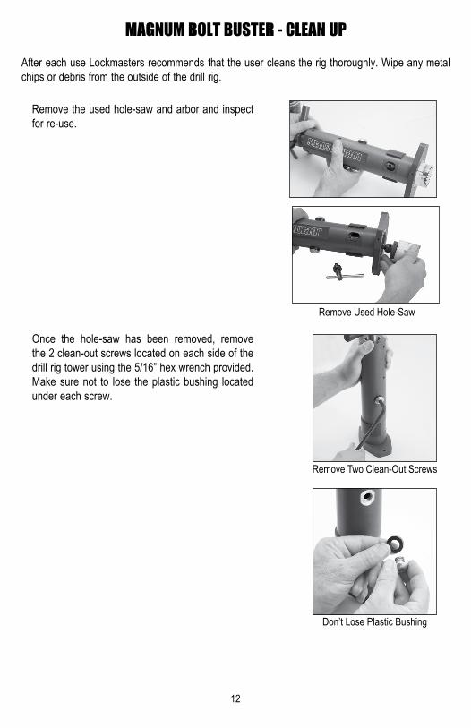
After each use Lockmasters recommends that the user cleans the rig thoroughly. Wipe any metal chips or debris from the outside of the drill rig.
Remove the used hole-saw and arbor and inspect for re-use.
Once the hole-saw has been removed, remove the 2 clean-out screws located on each side of the drillrigtowerusingthe5/16”hexwrenchprovided.Make sure not to lose the plastic bushing located under each screw.
MAGNUM BOLT BUSTER - CLEAN UP
Remove Two Clean-Out Screws
Don’t Lose Plastic Bushing
Remove Used Hole-Saw

13
Use canned air or an air compressor to blow out any debris, metal chips or dust that may have col-lected behind the hole-saw. Use the compressed air to thoroughly clean the inside of the barrel and drill chuck. Make sure to use a dust mask and eye protection while cleaning.
If left unchecked, this debris can cause damage to the drill quill feed mechanism.
Once the drill rig is clean, replace and tighten the clean-out screws and bushing and tighten. Return the drill rig in the case provided. Check for any missing or used parts and store in a dry area to prevent any rust build up while not in use.
MAGNUM BOLT BUSTER - CLEAN UP
Use Canned Air to Clean Rig
Cleaning Inside of Barrel
Replace Clean-Out Screw
Tighten The Clean-Out Screws

14
To help contain the majority of the smoke created while cutting the bolts, use duct tape to seal the seams of the container. Use the tap to sealthefirst2”holeonceitisfinished.
Once both bolts have been cut, use a shop vac withafineparticlefilter toremovethesmokefrom the container or take the container outside before opening the drawers and releasing the smoke.
MAGNUM BOLT BUSTER - TIP
Use Duct Tape to Seal Seams

2101 John C. Watts Drive • Nicholasville, KY 40356800.654.0637 • 859.885.6041 • Fax 859.885.7093www.lockmasters.com • [email protected]
MAG65702INST Copyright © 2013 Lockmasters, Inc.Revised 12/2013