Embed Size (px)
Citation preview
98573000 REV.REL
1302 WEST BEARDSLEY AVENUE • P.O. BOX 1127 • ELKHART IN 46515 • (574) 295-8330 • FAX (574) 293-9914 © 2015 ELKHART BRASS MFG. CO., INC.
65765001 eWON Cosy 131 Router
2
WARNING: This device is NOT rated for use in a hazardous location. Use in a hazardous location should be subject to the requirements of your electrical hot work permit procedure. Table of Contents: Configuration Page
I. Customer Set-Up Information 3-4 II. Field Configuration for WIFI (not required if unit is pre-configured at Elkhart Brass) 5
FAQ
III. Frequently Asked Questions 6-8
Network Security
IV. Network Security Synopsis 9
Attachments
Network Security – Detailed Analysis, for IP Professionals “An IT Perspective” eWON COSY 131 Equipment Manual Parameter Listing
3
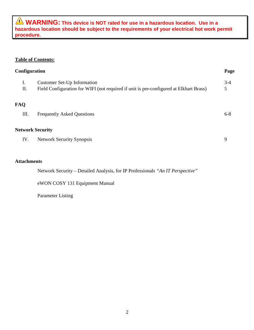
Customer Setup & Installation Requirements Overview 24VDC power must also be supplied to the eWON router. The eWON router needs access to the internet. This access can be achieved either through a wired Ethernet connection, or a wireless (WIFI) connection. It also needs to be connected to the Elkhart Brass Monitor network. This connection will be a wired Ethernet connection. Installation / Assembly / Power Step 1: Mounting the eWON (optional) For convenience, you may mount the router on an unused section of din rail. Slide the clear rail clip on the back of the router down until it clicks into the open position. Install the router onto the din rail and then push up on the clip untill it clicks and locks the router onto the din rail. Step 2: Antenna Installation (required for WIFI use): Install the antenna onto the router by hand tightening it on to the brass connector on the front of the router.
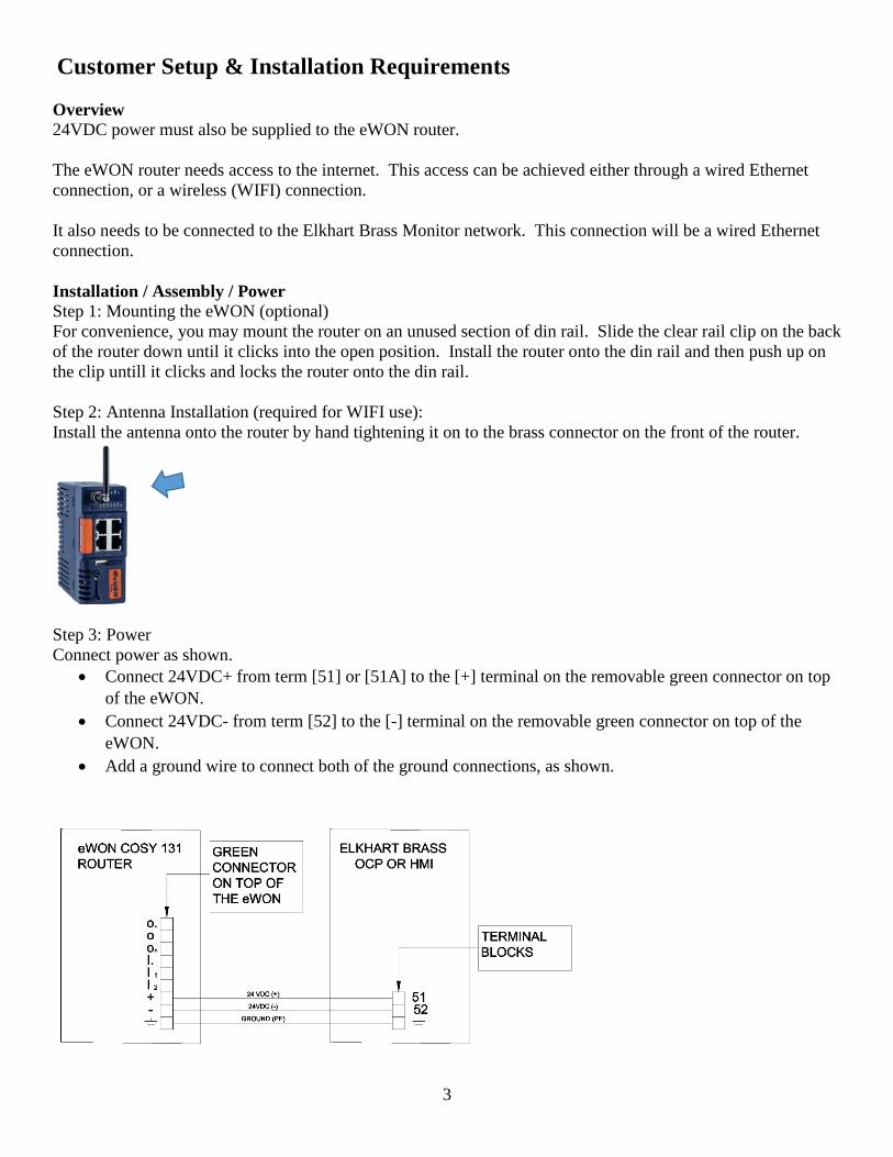
Step 3: Power Connect power as shown.
• Connect 24VDC+ from term [51] or [51A] to the [+] terminal on the removable green connector on top of the eWON.
• Connect 24VDC- from term [52] to the [-] terminal on the removable green connector on top of the eWON.
• Add a ground wire to connect both of the ground connections, as shown.
4
Internet Connection Optional Wired Internet Connection Plug an Ethernet cable from the plant network into the WAN port #4. This port is in the lower left corner and is the only one marked with a red LED when the switch is powered up. The cable can be a patch cable or a crossover cable. When the unit is powered up, the Switch will automatically obtain an IP address (DHCP) and will begin to work within a few minutes. Optional Wireless (WIFI) Internet Connection Potential wireless sources include:
• Plant WIFI • Wireless hotspots • Cell phones that have wireless hotspot capability • Dongles that have wireless hotspot capability
For use on WIFI, it is easiest if the switch is pre-configured at Elkhart Brass before it ships to the customer. In order to complete this, the customer must provide the following wireless network information:
• SSID • Password (a.k.a. passphrase) • Security Information (WEP, WPA, or none)
SSID and Password must not contain any special characters. SSID and Passwords are case sensitive, be sure to note them exactly. After the SSID and password are configured at Elkhart Brass, the unit will be shipped to the customer. The unit will then auto connect to their WIFI network automatically on power up. Elkhart Brass Network Connection Plug another Ethernet cable into any of the eWON’s LAN Ports; #1, or #2, or #3 (marked with a green LED). Plug the other end of that cable into any port, on any N-Tron switch, in the Elkhart Brass Monitor network. This cable can be a patch cable or a crossover cable.
5
II. Field Configuration for WIFI Note: Field configuration is not normally required. Elkhart Brass will usually pre-configure an eWON router before sending it to a customer. Field configuration of the PASSPHRASE, SSID, and SECURITY TYPE
1) Screw on the antenna.
2) Power up the EWON with a 24VDC power source (this can be a battery).
3) Connect an Ethernet cable (patch or crossover) to LAN port 1 of the EWON (upper right hand port).
4) Connect the other end of the cable to a computer’s Ethernet port.
5) Open a browser.
6) Type 192.168.32.131 in the browser address bar, press enter.
7) Select settings.
8) Type adm (lower case) for both the log in and the password.
9) Select the maintenance tab.
10) Check the box “show advanced options.”
11) Click on the hyperlink edit com config.
12) A very large table with all of the eWON’s parameters are shown. They should be listed in alphabetical order.
13) Scroll down to Find the parameter WifiPSK. This is the passphrase. It is shown encrypted. Double click on this parameter and write the new passphrase into the window that pops up. The new passphrase will automatically be encrypted. Note: the passphrase cannot contain any special characters. Press OK when complete.
14) Find the parameter WifiSSID. This is the SSID value. Double click on this parameter and enter the new SSID in the window that pops up. Note: The SSID cannot contain any special characters. Press OK when complete.
15) Find the parameter WifiSec. This is the security type. Double click and enter a number that represents the security type. 0 = no security, 1 = WEP, 2 = WPA. Press OK when complete.
16) Press SAVE and then REBOOT.
6
III. FREQUENTLY ASKED QUESTIONS ABOUT THE EWON What is the EWON and what can it be used for? EWON is a very high security router that can be connected into a network that controls Elkhart Brass monitors. Once connected, Elkhart Brass can log on to all the PLCs or HMIs on that network remotely through a secure internet connection. Tasks that it can be performed through it are: Remote commissioning of new systems. Remote commissioning of additions to systems. Remote troubleshooting. Remote software upgrades. Why should I buy an EWON from Elkhart Brass?
You will save money and time. Engineering fees for travel time are eliminated. Costs for airfare, hotel, car rental or mileage, tolls, parking, and meals, are all eliminated. Delays associated with travel arrangements are eliminated. Delays associated with engineering availability are nearly eliminated as it is much easier to find a few hours for an EWON service call verses a few days for an on-site call.
Is there a subscription fee? Beyond the one-time purchase price, there are no additional fees ever. Who can connect to it? Even though it will be owned by you the customer, it will be registered with the EWON corporation so that only Elkhart Brass can connect to it. Can it be used in a hazardous location? The EWON is not rated for use in a hazardous location. It can be temporarily used in a hazardous location only if the area is known to be free of flammable gases and vapors. It is often operated under an Electrical Hot Work Permit. Does it need to be installed permanently? No. It only needs to be installed for the short time it takes to perform a task, usually a few hours. It can then be removed or disabled by removing power to it, and/or disconnecting it from the internet connection. If I disconnect it and then have another need in the future, can I reconnect it? Yes, it can be used in the future for new installations, additions, troubleshooting, etc.
7
Does the eWON need to be connected to my business network? No. The eWON only needs access to the internet and the Elkhart Brass equipment network. Can Elkhart Brass access my sensitive business information through the eWON? Absolutely not. How do I connect it to the internet? The internet connection can be wired or wireless (WIFI). Any WIFI access point will work, such as a mobile hotspot, cell phone or dongle that can function as a mobile hotspot, or your business WIFI access. A wired connection from any network that has internet access will also work. Wired connections will configure automatically when the unit is powered up and the Ethernet cables are plugged in. WIFI connections need to be configured, but once configured, the unit will auto connect. The WIFI is set up by default with the following: SSID: ELKHART BRASS PASSPHRASE: ELKHART BRASS Can the SSID and passphrase be customized? The customer can send their desired SSID and passphrase to us and we can preconfigure their values into the unit. We will also need to know what type of encryption will be used (WEP, WPA, or none). NOTE: The SSID and passphrase cannot contain any special characters. Alternatively, Elkhart Brass can send instructions for field configuration of the unit. Can I use my GUEST wired or WIFI connection? Yes. Guest connections usually offer internet access only while blocking access to sensitive data that Elkhart Brass doesn’t need to see anyway. What makes the EWON connection secure? Encryption, and multiple technologies and procedures ensure a secure connection. CONNECTIONS: The EWON uses outbound connections over ports that are commonly left open by IT professionals because they are not considered a threat. Ports used are (TCP:443 and UDP:1194) and the EWON is compatible to most proxy servers and works within most existing firewall rules. PASSWORDS: Unique user logins, connection audit trail, double factor authentication. NETWORK INFRASTRUCTURE: Globally redundant Tier 1 hosting partners, 24/7 monitoring, SOC 1/SSAE 16/ISAE 3402 Data Centers, ISO270001, CSA ENCRYPTION: Sessions are via a virtual private network, and are end-to-end encrypted using SSL/TLS for session authentication and IP SEC ESP protocol for tunnel transport over UDP and TCP/IP. The connection is encrypted using a 2084-bit key exchange.

8
OTHER: IP, port, and protocol filtering/firewalling available. Restricted access granularity based on user, group, site for all or single devices or specific port. DEVICE LEVEL: Network segregation, local device authentication (MAC address). Is this established technology? EWON has hosted millions of VPN sessions for numerous customers since this product was launched in 2006. They are an Allen Bradley encompass partner. Allen Bradley is a dominant world leader in PLCs and automation equipment. You can’t ask for a better reference than that.
9
IV. Network Security Synopsis Everybody is concerned these days about the security of their internet connections. This is exactly why Elkhart Brass is using eWON and their services; because they have unparalleled security. A document that touts all the security measures in detail is attached, but it is hard to read unless you are a network expert. Here is a less technical synopsis:
• Outbound connections are made through ports that are typically left open by IT professionals because your sensitive data can’t be accessed through these ports (port 443 (HTTPS) or UDP 1194). Therefore, changes to your firewall settings are usually not required.
• The connection will be through a VPN tunnel, which is invisible on the internet to hackers. There will
be no IP address facing the internet. This is the most secure way to communicate on the internet.
• The connection is encrypted using a 2084-bit key exchange.
• Password authentication and MAC address authentication are used.
• eWON is an encompass partner with Rockwell Automation, the leaders in the PLC world. There is no better reference than that.
eWON Security Paper
Secure Industrial Automation
Remote Access Connectivity
Using eWON and Talk2M Pro solutions
Last Modified: January 13, 2015
www.ewon.us
eWON Layered Security Approach |
© 2015 eWON Inc. This document is property of eWON Inc.
2
Overview
eWON is a global provider of secure industrial remote access connectivity. By
leveraging a combination of its cloud based, redundant infrastructure called Talk2M
and its industrial eWON hardware devices, eWON created a first-to-market
integrated approach to secure remote access to industrial control systems. Since its
launch in 2006, eWON’s Talk2M has successfully hosted millions of encrypted VPN
sessions allowing engineers to easily and securely remotely monitor and troubleshoot
their machines.
Challenges
Remote access has posed numerous challenges for decades. Various solutions
including modems, traditional VPNs, IT client software and IP Sec routers have failed
to offer a repeatable and secure, reliable solution that is simple to configure,
manage, deploy and use.
Customers have different network topologies, requirements and technical
competencies. The biggest challenge remains being compatible with existing
customer networks and industrial automation and control system (IACS) architecture.
Approach
Understanding the challenges associated with securely deploying and managing
remote access within an IACS, eWON developed a solution compatible with industry
accepted open standards that addresses the following key areas related to secure
remote access in a defense-in-depth layered approach;
Policies & procedures
Network Infrastructure
Management & Accountability
Encryption
Application
eWON Hardware Devices
Benefits
The benefits of leveraging the eWON Solution include;
Mitigating risks by improving uptime and equipment availability and efficiency
with managed secure remote access, users and devices.
Reduce onsite travel.
Reducing mean-time-to-repair (MTTR).
Lowering the total cost of ownership (TCO) of the IACS remote access
approach.
Professionally managed globally redundant cloud infrastructure.
Compatible with industry standards (SSL and VPN).
eWON Layered Security Approach |
© 2014 eWON Inc. This document is property of eWON Inc.
3
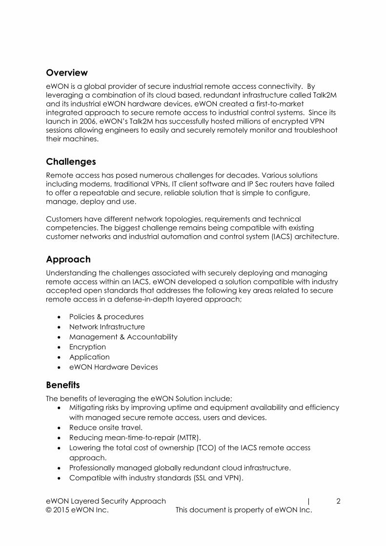
The eWON Security Approach
Using a defense-in-depth approach based on guidelines set forth by ISO27002, IEC
62443-2-4 and NIST Cyber security Framework 1.0 in addition to numerous other
publications, guidelines and industry best practices, eWON developed a managed,
hybrid, layered cyber security approach to protect its devices, network and most
importantly, its customers’ industrial control systems.
Talk2M Network Infrastructure:
Globally redundant Tier 1 hosting
partners, 24/7 monitoring, SOC
1/SSAE 16/ISAE 3402 Data
Centers, ISO270001, CSA
Management & Accountability:
Unique user logins, configurable
user rights to different devices.
Connection audit trail. Double
factor authentication.
Encryption: VPN sessions are end-
to-end encrypted using SSL/TLS for
session authentication and IP SEC
ESP protocol for tunnel transport
over UDP and TCP/IP
Application: IP, port, and protocol
filtering/firewalling available.
Restricted access granularity
based on user, group, site for all or
single devices or specific port.
eWON Device: Network
segregation, local device
authentication, physical switch for
enabling/disabling access.
Policies & Procedures:
eWON/Talk2M solution enhances
and is compatible with existing
corporate security policies,
firewall rules, and proxy servers.
Policies &
Procedures
Talk2M Network Infrastructure
User Management & Accountability
Encryption
Application
eWON
Device
eWON, the global leader in secure
industrial automation remote access,
considers device and network security to
be a core competency fully integrated at
every level within the framework of our
solution.
eWON Layered Security Approach |
© 2015 eWON Inc. This document is property of eWON Inc.
4
Security Vs Convenience and Acceptance One of the key challenges with remote connections to industrial control systems is
balancing the needs of an engineer or PLC technician with the mandate by the IT
department to ensure network security, integrity and reliability. Finding a solution that
is readily accepted by both business groups has been a challenge for many years
and a source of frustration and inefficiency for all stakeholders. eWON understood
that maintaining network security was essential for IT acceptance. At the same time,
eWON realized users will never use solutions that are complex, difficult or interrupt
productivity. By balancing both the security and ease of use, eWON has created a
best-in-class Remote Access solution that works for both end users and IT managers.
The eWON Layered Security Approach
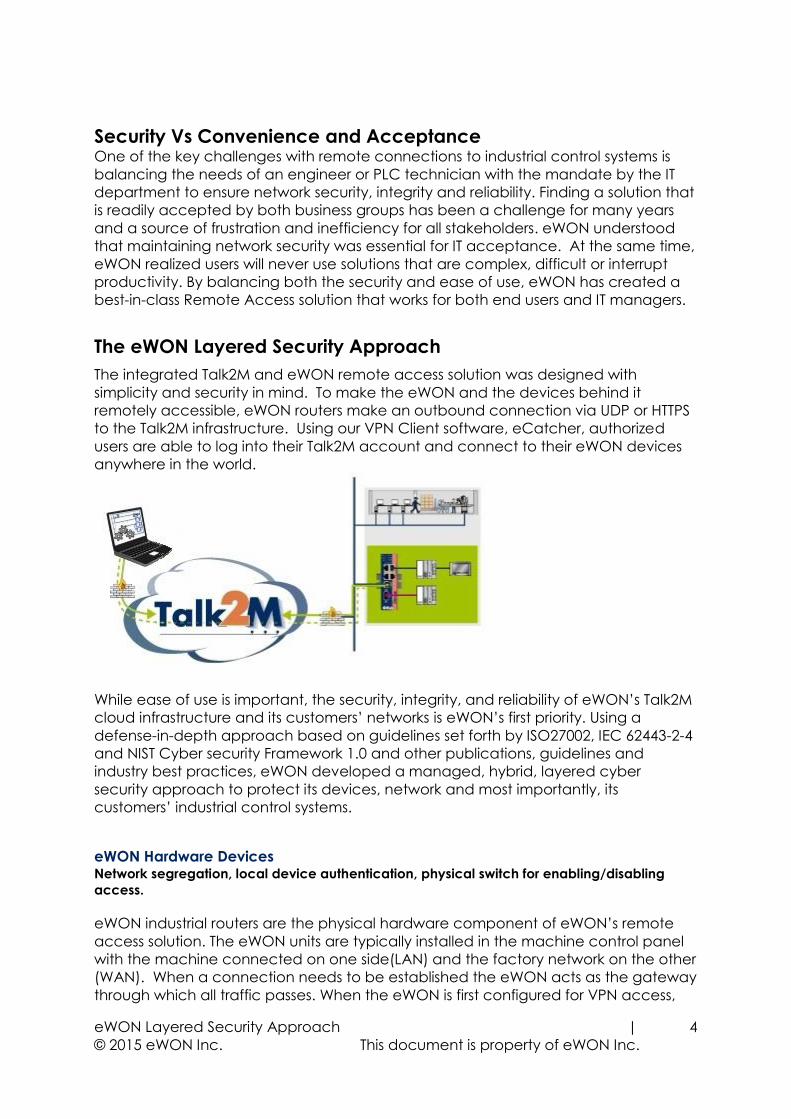
The integrated Talk2M and eWON remote access solution was designed with
simplicity and security in mind. To make the eWON and the devices behind it
remotely accessible, eWON routers make an outbound connection via UDP or HTTPS
to the Talk2M infrastructure. Using our VPN Client software, eCatcher, authorized
users are able to log into their Talk2M account and connect to their eWON devices
anywhere in the world.
While ease of use is important, the security, integrity, and reliability of eWON’s Talk2M
cloud infrastructure and its customers’ networks is eWON’s first priority. Using a
defense-in-depth approach based on guidelines set forth by ISO27002, IEC 62443-2-4
and NIST Cyber security Framework 1.0 and other publications, guidelines and
industry best practices, eWON developed a managed, hybrid, layered cyber
security approach to protect its devices, network and most importantly, its
customers’ industrial control systems.
eWON Hardware Devices Network segregation, local device authentication, physical switch for enabling/disabling
access.
eWON industrial routers are the physical hardware component of eWON’s remote
access solution. The eWON units are typically installed in the machine control panel
with the machine connected on one side(LAN) and the factory network on the other
(WAN). When a connection needs to be established the eWON acts as the gateway
through which all traffic passes. When the eWON is first configured for VPN access,
eWON Layered Security Approach |
© 2014 eWON Inc. This document is property of eWON Inc.
5
security settings on the device restrict traffic between its two network interfaces. This
network segregation limits remote access to only those devices connected to the
LAN of the eWON. Access to the rest of the network is prevented.
The eWONs themselves have user-level access rights separate from the Talk2M login.
Only users with appropriate credentials and access rights can change the security
settings on the eWON. Similarly, for the devices with data services, only authorized
users can view or modify the data.
All of our hardware devices feature a digital input. A switch can be connected to
this input and the state of the switch can enable or disable the WAN port. This allows
the end user to keep full local control of whether or not the device is remotely
accessible.
The eWON needs the same type of settings as a PC connected to the same network
(IP address, subnet mask and gateway, plus any optional proxy settings). Since the
eWON can act as a DHCP client, it can be configured to receive those settings
automatically. However, the eWON also can be set up to use a static IP address that
is assigned and controlled by the IT department if preferred.
Application IP, port, and protocol filtering/firewalling available. Restricted access based on user, group,
site for all or single devices or specific port.
Within the eCatcher application, Talk2M account administrators can set filtering and
firewalling rules about which devices behind the eWON are remotely accessible and
even over which ports and with which protocols they are accessible. When
combined with Talk2M’s user rights management discussed below, Talk2M
administrators have the ability to tailor the remote access rights to fit their
organizational structure.
Encryption VPN sessions are end-to-end encrypted using SSL/TLS for session authentication and IP SEC
ESP protocol for tunnel transport over UDP and TCP/IP.
Communications between the remote user and the eWON are fully encrypted. All
users and eWON units are authenticated using SSL/TLS for HTTPS session
authentication and the IPSec ESP protocol for secure transport over UDP. Talk2M
supports the X509 PKI for session authentication, TLS for key exchange, the cipher-
independent EVP interface for encrypting tunnel data, and the HMAC-SHA1
algorithm for authenticating tunnel data.
Management & Accountability Unique user logins, configurable user rights to different devices, connection traceability.
A Talk2M account may have an unlimited number of users. Administrators can
create unique logins for every user who needs to access equipment remotely. These
unique logins makes it easy to grant and revoke access privileges as needed. In
addition, Talk2M account administrators can restrict which remote eWONs particular
users can access, which devices behind those eWON are accessible and even the
ports on those devices and the communication protocols used. For instance, an
administrator might permit remote users to reach the web services in a particular
eWON Layered Security Approach |
© 2015 eWON Inc. This document is property of eWON Inc.
6
device for monitoring purposes but limit the ports used for making programing
changes to only specific engineers.
Every remote connection is documented on the Talk2M Connection report. The
Talk2M Connection report is a powerful IT auditing tool which allows account
administrators to monitor which users are connected to which eWON and when and
for how long they were connected.
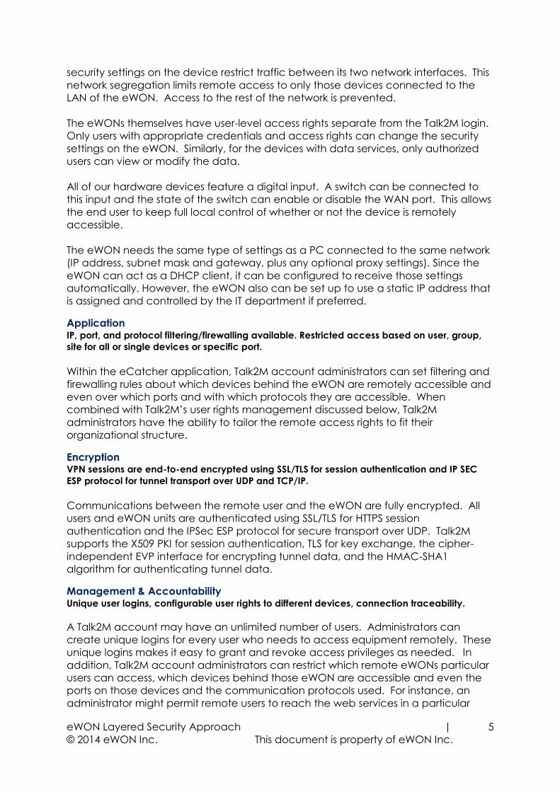
Network Infrastructure Globally redundant Tier 1 hosting partners, 24/7 monitoring, SOC 1/SSAE 16/ISAE 3402 Data
Centers, ISO270001, CSA, SOC2.
The Talk2M infrastructure is a critical integrated element in our remote access
solution. It is a fully redundant network of distributed access servers, VPN servers, and
other services that act as the secure meeting place for eWONs and users. To
increase reliability, redundancy and reduce latency, eWON works with multiple
industry leading Tier 1, 2 and 3 hosting partners throughout the world to ensure best in
class service. Talk2M is hosted in SOC 1/SSAE 16/ISAE 3402 and ISO 27001 certified
data centers. The network of servers is monitored 24/7 to ensure maximum availability
and security using intrusion detection systems (IDS), host intrusion prevention systems
(HIPS) in addition to an array of alerting mechanisms.
Policies & Procedures The eWON/Talk2M solution enhances and is compatible with existing corporate security
policies, firewall rules, and proxy servers.
eWON understands that its customer designed their corporate security policies
carefully. The Talk2M remote access solution is designed to be compatible with
customers’ existing security policies. By using outbound connections over commonly
open ports (TCP:443 and UDP:1194) and by being compatible to most proxy servers,
the eWON is designed to be minimally intrusive on the network and work within the
existing firewall rules. Within eCatcher, Talk2M account administrators can customize
the password policies to force compliance to corporate password policies and can
restrict which users can access which devices remotely. Talk2M account
administrators can also view the Talk2M Connection report to see which users are
connecting to which eWON devices and when. This report can be a valuable tool
to ensure that your corporate remote access policies are being followed.
eWON Layered Security Approach |
© 2014 eWON Inc. This document is property of eWON Inc.
7
Summary A combination of unique hardware and globally redundant cloud infrastructure creates a
robust, secure and convenient method to enable encrypted remote access to machines,
panels and other industrial automation devices.
The key added-value of Talk2M is the full integration of IT security standards by
allowing an Internet communication tunnel between the user and the remote
machine while still following the existing firewall rules and security policies of each
network. This means little or no IT changes required and gives organizations the
ultimate solution to manage their Remote Access needs with maximum control,
visibility and security.
Technical Contact Information
In the U.S. contact;
eWON Inc.
Tel: (412) 586-5901 Fax: (412) 586-5920
Web: www.ewon.us Email: [email protected]
2345 Murray Ave, Suite 305, Pittsburgh, PA 15217
More information is available on our website at www.ewon.us or visit our support site
at: http://support.ewon.biz
Worldwide Offices:
United States Belgium Japan
support.ewon.biz
eWON COSY 131This installation guide describes the hardware of the eWON COSY 131 and explains how to get started with the embedded web site.
Installation Guide
IG 022 / Rev. 1.7
Table of Contents
1. Product Summary ............................................................................................................. 41.1. Introduction ...................................................................................................................................... 41.2. Concept of the eWON COSY 131 Family ................................................................................... 41.3. General specification of the hardware platform ..................................................................... 41.4. Typical applications ........................................................................................................................ 51.5. Type and Part Numbers ................................................................................................................. 5
2. Safety, Environmental & Regulatory Information ........................................................... 62.1. Scope ................................................................................................................................................ 62.2. Power supply .................................................................................................................................... 62.3. Applicable Directives, Standards and Compliance ................................................................ 6
2.3.1. Applicable European Directives ........................................................................................ 62.3.2. Applicable Safety Standards ............................................................................................. 72.3.3. FCC Compliance .................................................................................................................. 72.3.4. Certifications .......................................................................................................................... 7
2.4. Field implementation & environmental conditions .................................................................. 72.4.1. Ingress Protection .................................................................................................................. 72.4.2. Mounting Recommendations ............................................................................................ 82.4.3. Cabling rules ........................................................................................................................ 102.4.4. Environmental conditions .................................................................................................. 102.4.5. Earthing ................................................................................................................................. 10
2.5. Battery ............................................................................................................................................. 10
3. Hardware description .................................................................................................... 113.1. Label ................................................................................................................................................ 113.2. Mechanical dimensions ............................................................................................................... 133.3. Overall description ........................................................................................................................ 13
3.3.1. Front ....................................................................................................................................... 133.3.2. Upper side ............................................................................................................................ 143.3.3. Status LED (COSY 131 – All version) ................................................................................. 14 3.3.3.1. WiFi Status LED (EC6133C) ........................................................................................... 15 3.3.3.2. Cellular Modem Status LED (EC6133D - EC6133E) .................................................. 15
3.4. Radio communication models ................................................................................................... 163.4.1. COSY 131 with internal WiFi modem ............................................................................... 163.4.2. COSY 131 with internal 3G+ Penta-band modem ....................................................... 173.4.3. COSY 131 with internal 4G JP Quad-band modem .................................................... 18
3.5. LAN Switch Specifications ........................................................................................................... 193.5.1. Boot process ........................................................................................................................ 193.5.2. LAN Switch configuration .................................................................................................. 19
4. COSY IP Address & Access to the Web Configuration ................................................ 204.1. Factory Default IP settings ........................................................................................................... 204.2. Powering ON .................................................................................................................................. 204.3. Connecting to the eWON COSY LAN IP Address .................................................................. 204.4. eWON COSY's Web Interface .................................................................................................... 21
5. Troubleshooting .............................................................................................................. 225.1. Normal Boot Process ..................................................................................................................... 22
Page 2 / 32 eWON COSY 131 | IG 022
Table of Contents
5.2. Resetting the eWON COSY 131 .................................................................................................. 225.2.1. First Level Reset (user reset) .............................................................................................. 225.2.2. Second Level Reset (factory reset) ................................................................................. 22
5.3. Reset Impact Matrix ...................................................................................................................... 23
Appendix A - Connector Pinout & Related Specifications ............................................. 24A.1 - Main Connector ......................................................................................................................... 24A.2 - Specification of the External Power Supply ........................................................................... 25A.3 - Digital Output & Digital Inputs .................................................................................................. 25A.4 - Supported Wireless WiFi Frequencies ...................................................................................... 28
Revision .............................................................................................................................. 30 Revision History ..................................................................................................................................... 30
Page 3 / 32 eWON COSY 131 | IG 022
Chapter 1Product Summary
1. Product Summary
1.1. IntroductionThe present Installation Guide describes the hardware of the eWON COSY 131 family.
The eWON Cosy 131 family is a set of industrial gateways/routers fully compatible with the Talk2M cloud connectivity services (www.talk2M.com).
1.2. Concept of the eWON COSY 131 FamilyThe Cosy 131 is available in different versions depending on their communication media:
• Ethernet Switch Cosy 131 Ethernet
• WiFi & Ethernet Switch Cosy 131 WiFi
• 3G+ & Ethernet Switch Cosy 131 Cellular 3G+
• 4G & Ethernet Switch Cosy 131 4G JP
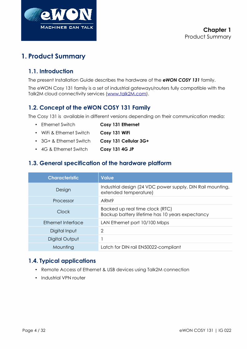
1.3. General specification of the hardware platform
Characteristic Value
DesignIndustrial design (24 VDC power supply, DIN Rail mounting,extended temperature)
Processor ARM9
ClockBacked up real time clock (RTC)Backup battery lifetime has 10 years expectancy
Ethernet Interface LAN Ethernet port 10/100 Mbps
Digital Input 2
Digital Output 1
Mounting Latch for DIN rail EN50022-compliant
1.4. Typical applications• Remote Access of Ethernet & USB devices using Talk2M connection
• Industrial VPN router
Page 4 / 32 eWON COSY 131 | IG 022
Chapter 1Product Summary
1.5. Type and Part NumbersThe available part numbers are:
Part Number Type Description
EC61330_00MA COSY 131 LAN/WAN – Ethernet Only 4-Port Switch
EC6133C_00MA COSY 131 LAN/WAN, WIFI – Ethernet Switch
EC6133D_01MA COSY 131 LAN/WAN, 3G+ Penta-band - Ethernet Switch
EC6133E_00MA COSY 131 LAN/WAN, 4G Quad-band (Japan) - Ethernet Switch
Table: List of the available part numbers
- Note -
The MA suffix means Multiple languages A (UK, FR, DE, ES, IT)
The part number syntax is explained in 3.1. Label
Page 5 / 32 eWON COSY 131 | IG 022
Chapter 2Safety, Environmental & Regulatory Information
2. Safety, Environmental & Regulatory Information
2.1. ScopeThe present chapter addresses Safety, Environmental & Regulatory Information for the eWON Cosy 131 family.
2.2. Power supplyThe external power supply is a third party device that is not part of this certification.
The device shall be powered by a LPS power supply certified according to IEC/UL60950-1 or Class 2 per NEC (See annex A.2. Specification of the External Power Supply for detailed information).
2.3. Applicable Directives, Standards and ComplianceThe product described in the present Installation Guide complies with the CE, RE directives and the FCC regulations related to the wireless modems.
The product described in the present Installation Guide belongs to class A Information Technology Equipment (ITE). In a domestic environment this product may cause radio interference in which case the user may be required to take appropriate measures.
2.3.1. Applicable European Directives
The product described in the present Installation Guide is in conformity with the following ECdirectives:
• RoHS Directive 2011/65/EU
• EMC Directive 2014/30/EU
• RE directive 2014/53/EU (for versions including RF modems)The product conforms to the corresponding R&TTE articles:RF Spectrum efficiency, Art. 3(2); EMC, Art. 3(1)(b); Safety, Art. 3(1)(a);
• REACH Directive 2006/121/EC
• For COSY 131, Cellular 3G+ only: to comply with RE directive
• Antenna must be mounted on a grounded plate
2.3.2. Applicable Safety Standards
The product described in the present Installation Guide is in conformity with the following safety standards:
• IEC/EN 60950-1
• UL 60950-1
Page 6 / 32 eWON COSY 131 | IG 022
Chapter 2Safety, Environmental & Regulatory Information
• CSA-C22.2 No 60950-1-07
2.3.3. FCC Compliance
The product described in the present Installation Guide complies with Part 15 of the FCC Rules. Operating is subject to the following two conditions:
• This device may not cause harmful interference, and
• This device must accept any interference received, including interference that may cause undesired operation.
2.3.4. Certifications
The product described in the present Installation Guide has been certified by authorized bodies:
• UL Certificate Of Compliance (CoC) for Ordinaty Locations # E350576 for a TMRA of 60°C
• CB certificate # DK-42240-UL
These certificates can be downloaded as PDF files on the eWON Support web site:https://ewon.biz/support/docs/cosy-131#5
2.4. Field implementation & environmental conditions
2.4.1. Ingress Protection
The eWON COSY 131 has an IP20 protection grade. Therefore, the eWON COSY is NOT suitedfor outdoor mounting. It has to be integrated in an electrical cabinet, protected from excessive heat, humidity and dust. Do not push any sharp object into the air vents or openings of the equipment.
2.4.2. Mounting Recommendations
The normal mounting position of the eWON COSY is wall mounted on a horizontal Omega type DIN-rail (EN 50022).
• Mounting the unit on DIN-railPull the slide lock (located at the bottom of the back-side of the unit) downwards andpresent the unit in front of the DIN rail. Tilt the eWON upwards in order to hang it on theupper edge of the DIN rail by its hook. Gently tilt the unit downwards until it finds its
Page 7 / 32 eWON COSY 131 | IG 022
Chapter 2Safety, Environmental & Regulatory Information
original position. Pull the slide lock upwards to fix and lock the unit on the DIN rail.
• Removing the unit from DIN-railRelease the unit by pulling the slide lock downwards while gently tilting the unit upwards. Free the unit by unhooking it from the upper rail edge. See 2.4.2 Mounting instructions
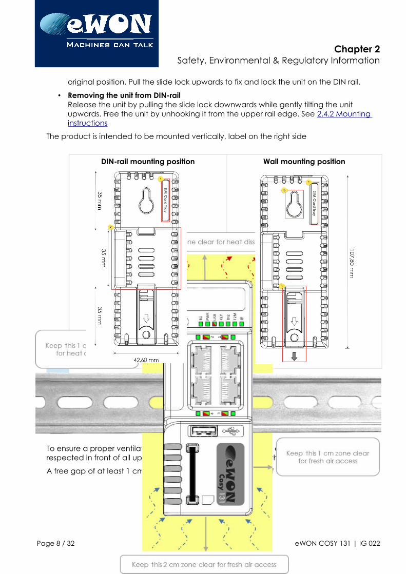
The product is intended to be mounted vertically, label on the right side
DIN-rail mounting position Wall mounting position
1 SIM card slot
2 DIN rail mounting bracket
3 Screw holes intended to receive M4 screws with an 8mm diameter head
To ensure a proper ventilation of the equipment, a free gap of at least 2 cm must be respected in front of all upper & lower ventilation openings of the unit.
A free gap of at least 1 cm must be respected on each side of the unit.
Page 8 / 32 eWON COSY 131 | IG 022
Chapter 2Safety, Environmental & Regulatory Information
- Caution -
In any other mounting position than the one explained here above, the specified temperature has to be derated to -25°C to +40°C.
2.4.3. Cabling rules
Shielded cables must be used for Ethernet and USB connectivity to comply with the EMC requirements.
USB cable must be:
• shorter than 3m
Page 9 / 32 eWON COSY 131 | IG 022
Chapter 2Safety, Environmental & Regulatory Information
• USB 2.0 type A (on the eWON side)
• Minimum current per contact : 0.5A (or better)
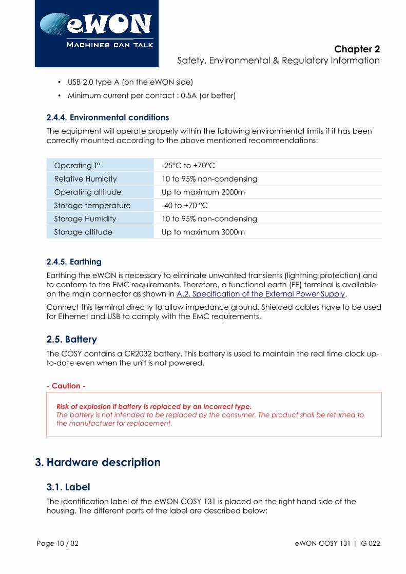
2.4.4. Environmental conditions
The equipment will operate properly within the following environmental limits if it has been correctly mounted according to the above mentioned recommendations:
Operating T° -25°C to +70°C
Relative Humidity 10 to 95% non-condensing
Operating altitude Up to maximum 2000m
Storage temperature -40 to +70 °C
Storage Humidity 10 to 95% non-condensing
Storage altitude Up to maximum 3000m
2.4.5. Earthing
Earthing the eWON is necessary to eliminate unwanted transients (lightning protection) and to conform to the EMC requirements. Therefore, a functional earth (FE) terminal is available on the main connector as shown in A.2. Specification of the External Power Supply.
Connect this terminal directly to allow impedance ground. Shielded cables have to be usedfor Ethernet and USB to comply with the EMC requirements.
2.5. BatteryThe COSY contains a CR2032 battery. This battery is used to maintain the real time clock up-to-date even when the unit is not powered.
- Caution -
Risk of explosion if battery is replaced by an incorrect type.The battery is not intended to be replaced by the consumer. The product shall be returned to the manufacturer for replacement.
3. Hardware description
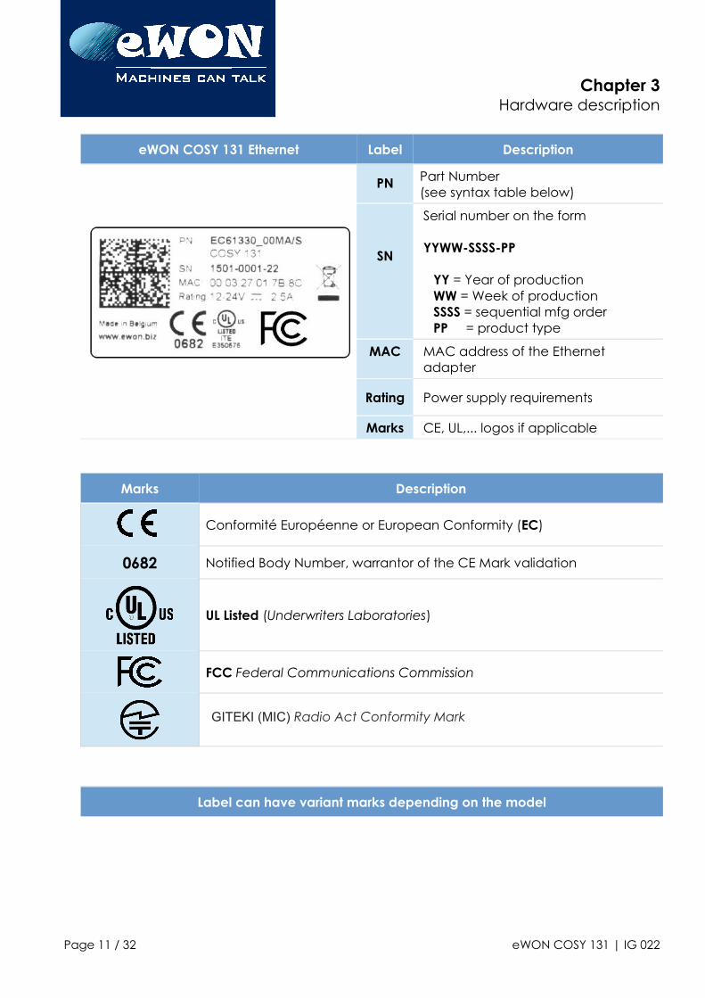
3.1. LabelThe identification label of the eWON COSY 131 is placed on the right hand side of the housing. The different parts of the label are described below:
Page 10 / 32 eWON COSY 131 | IG 022
Chapter 3Hardware description
eWON COSY 131 Ethernet Label Description
PN Part Number(see syntax table below)
SN
Serial number on the form
YYWW-SSSS-PP
YY = Year of productionWW = Week of productionSSSS = sequential mfg orderPP = product type
MAC MAC address of the Ethernet adapter
Rating Power supply requirements
Marks CE, UL,... logos if applicable
Marks Description
Conformité Européenne or European Conformity (EC)
0682 Notified Body Number, warrantor of the CE Mark validation
UL Listed (Underwriters Laboratories)
FCC Federal Communications Commission
GITEKI (MIC) Radio Act Conformity Mark
Label can have variant marks depending on the model
Page 11 / 32 eWON COSY 131 | IG 022
Chapter 3Hardware description
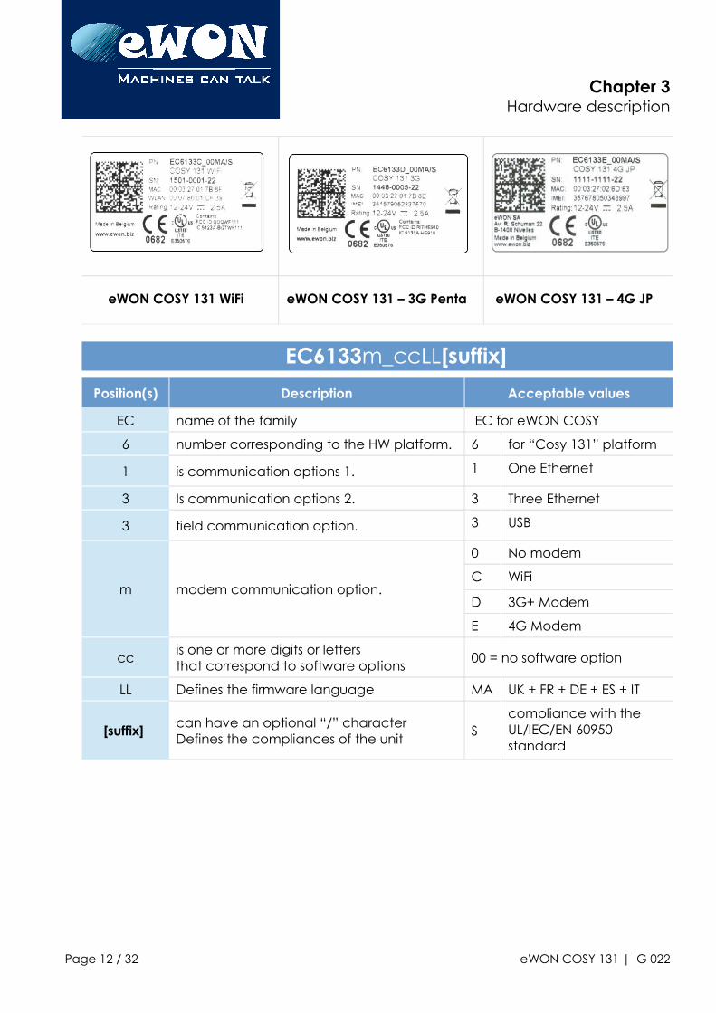
eWON COSY 131 WiFi eWON COSY 131 – 3G Penta eWON COSY 131 – 4G JP
EC6133m_ccLL[suffix]
Position(s) Description Acceptable values
EC name of the family EC for eWON COSY
6 number corresponding to the HW platform. 6 for “Cosy 131” platform
1 is communication options 1. 1 One Ethernet
3 Is communication options 2. 3 Three Ethernet
3 field communication option. 3 USB
m modem communication option.
0 No modem
C WiFi
D 3G+ Modem
E 4G Modem
ccis one or more digits or letters that correspond to software options
00 = no software option
LL Defines the firmware language MA UK + FR + DE + ES + IT
[suffix]can have an optional “/” character Defines the compliances of the unit
Scompliance with the UL/IEC/EN 60950 standard
Page 12 / 32 eWON COSY 131 | IG 022
Chapter 3Hardware description
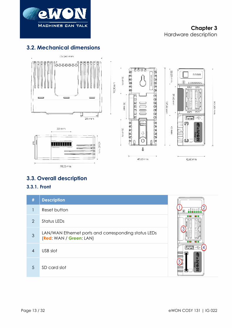
3.2. Mechanical dimensions
3.3. Overall description3.3.1. Front
# Description
1 Reset button
2 Status LEDs
3LAN/WAN Ethernet ports and corresponding status LEDs (Red: WAN / Green: LAN)
4 USB slot
5 SD card slot
Page 13 / 32 eWON COSY 131 | IG 022
Chapter 3Hardware description
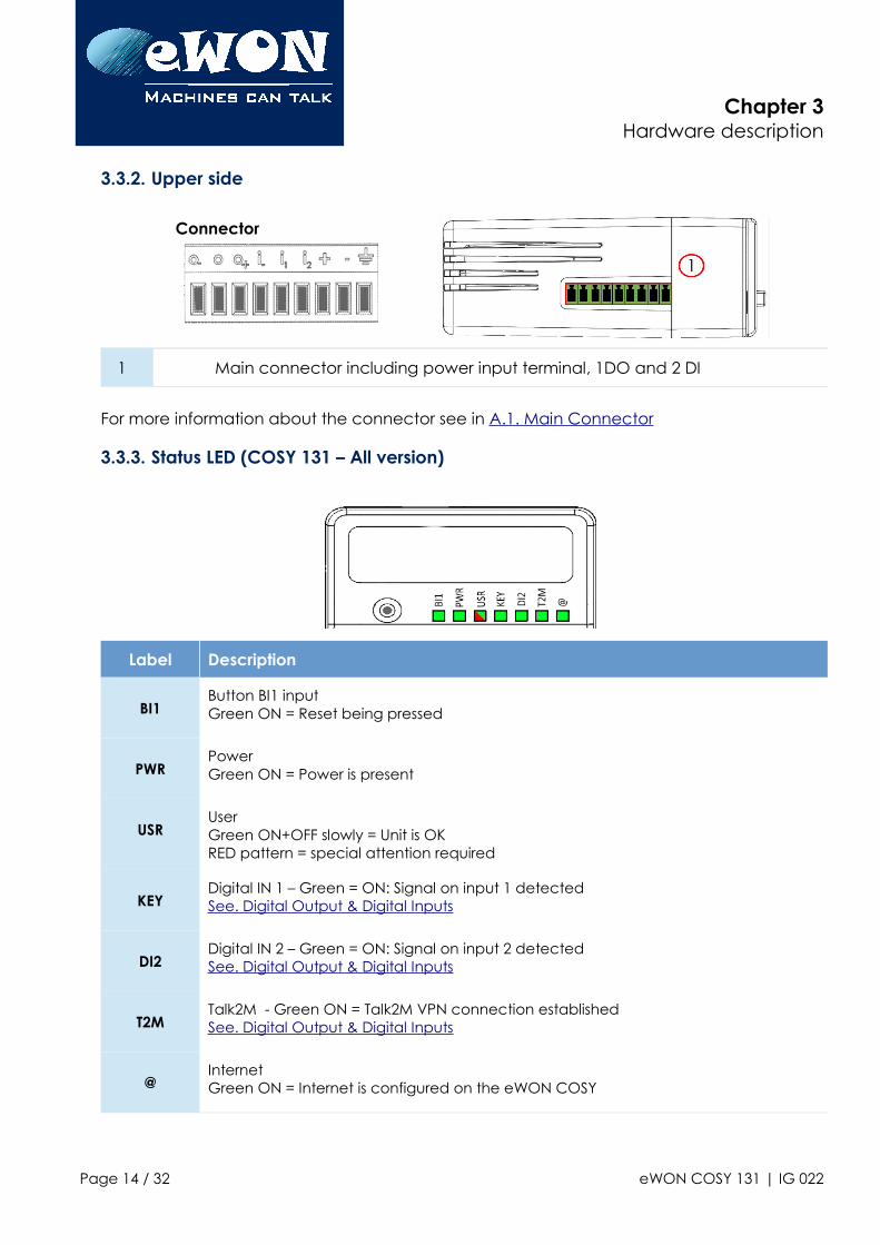
3.3.2. Upper side
Connector
1 Main connector including power input terminal, 1DO and 2 DI
For more information about the connector see in A.1. Main Connector
3.3.3. Status LED (COSY 131 – All version)
Label Description
BI1Button BI1 inputGreen ON = Reset being pressed
PWRPower Green ON = Power is present
USRUserGreen ON+OFF slowly = Unit is OKRED pattern = special attention required
KEYDigital IN 1 – Green = ON: Signal on input 1 detectedSee. Digital Output & Digital Inputs
DI2Digital IN 2 – Green = ON: Signal on input 2 detectedSee. Digital Output & Digital Inputs
T2MTalk2M - Green ON = Talk2M VPN connection establishedSee. Digital Output & Digital Inputs
@Internet Green ON = Internet is configured on the eWON COSY
Page 14 / 32 eWON COSY 131 | IG 022
Chapter 3Hardware description
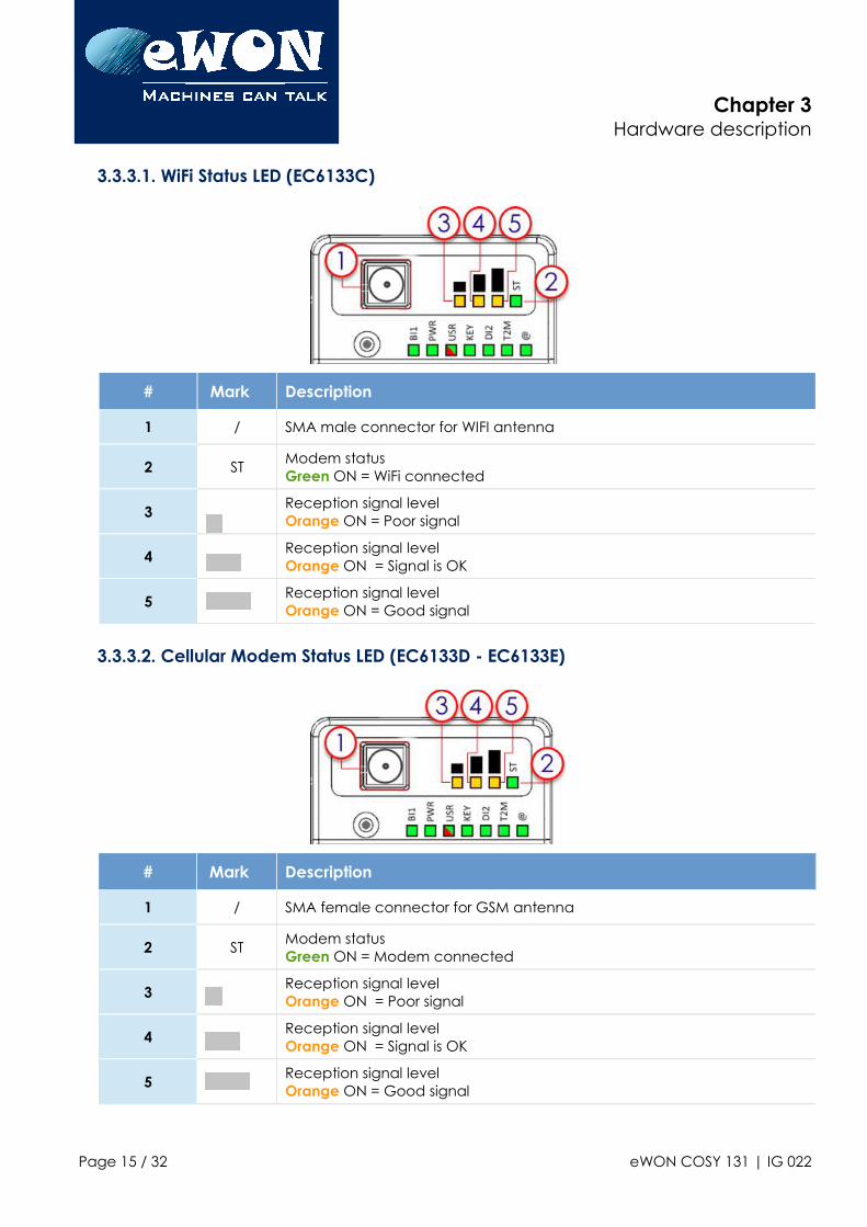
3.3.3.1. WiFi Status LED (EC6133C)
# Mark Description
1 / SMA male connector for WIFI antenna
2 STModem status Green ON = WiFi connected
3Reception signal levelOrange ON = Poor signal
4Reception signal levelOrange ON = Signal is OK
5Reception signal levelOrange ON = Good signal
3.3.3.2. Cellular Modem Status LED (EC6133D - EC6133E)
# Mark Description
1 / SMA female connector for GSM antenna
2 STModem status Green ON = Modem connected
3Reception signal levelOrange ON = Poor signal
4Reception signal levelOrange ON = Signal is OK
5Reception signal levelOrange ON = Good signal
Page 15 / 32 eWON COSY 131 | IG 022
Chapter 3Hardware description
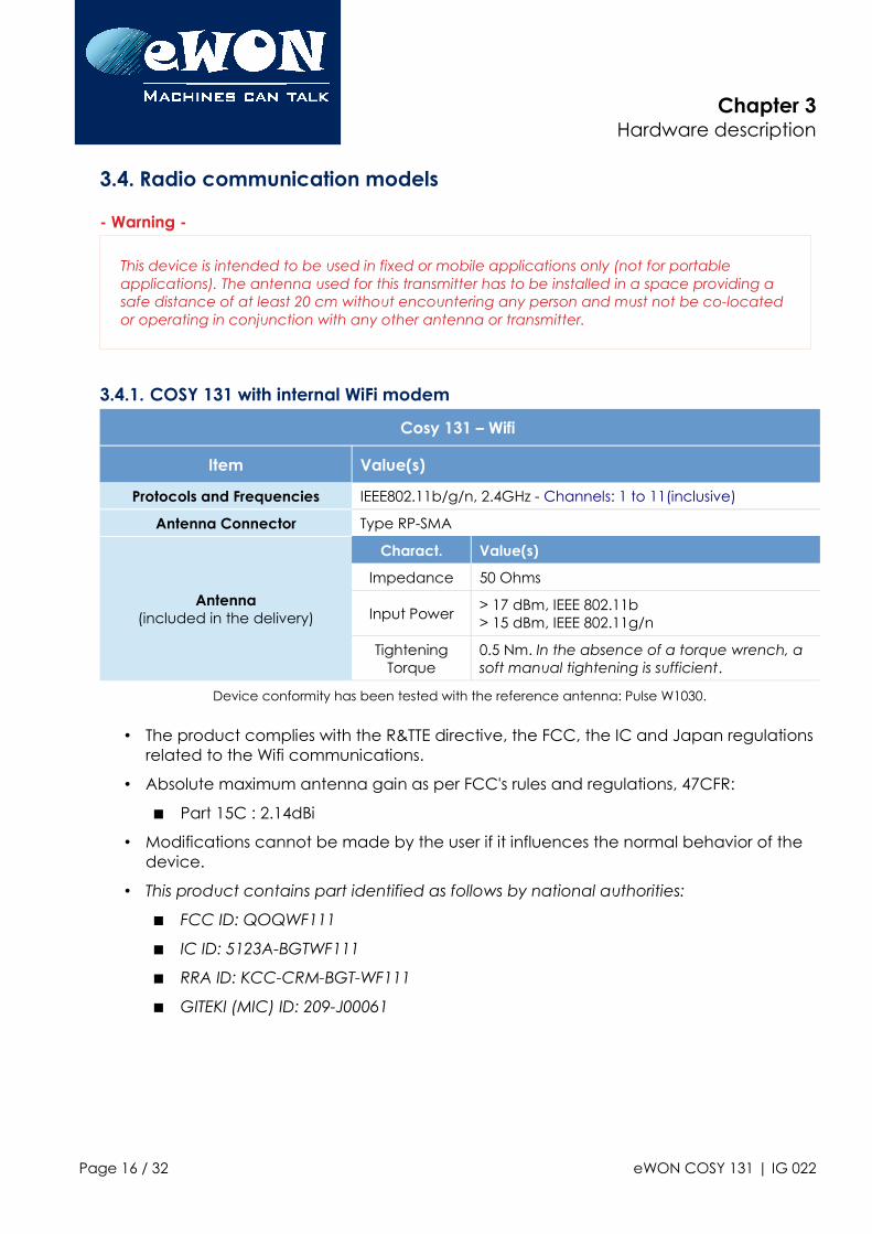
3.4. Radio communication models
- Warning -
This device is intended to be used in fixed or mobile applications only (not for portable applications). The antenna used for this transmitter has to be installed in a space providing a safe distance of at least 20 cm without encountering any person and must not be co-located or operating in conjunction with any other antenna or transmitter.
3.4.1. COSY 131 with internal WiFi modem
Cosy 131 – Wifi
Item Value(s)
Protocols and Frequencies IEEE802.11b/g/n, 2.4GHz - Channels: 1 to 11(inclusive)
Antenna Connector Type RP-SMA
Antenna(included in the delivery)
Charact. Value(s)
Impedance 50 Ohms
Input Power> 17 dBm, IEEE 802.11b> 15 dBm, IEEE 802.11g/n
TighteningTorque
0.5 Nm. In the absence of a torque wrench, a soft manual tightening is sufficient.
Device conformity has been tested with the reference antenna: Pulse W1030.
• The product complies with the R&TTE directive, the FCC, the IC and Japan regulations related to the Wifi communications.
• Absolute maximum antenna gain as per FCC's rules and regulations, 47CFR:
Part 15C : 2.14dBi
• Modifications cannot be made by the user if it influences the normal behavior of the device.
• This product contains part identified as follows by national authorities:
FCC ID: QOQWF111
IC ID: 5123A-BGTWF111
RRA ID: KCC-CRM-BGT-WF111
GITEKI (MIC) ID: 209-J00061
Page 16 / 32 eWON COSY 131 | IG 022
Chapter 3Hardware description
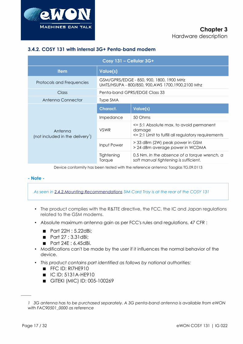
3.4.2. COSY 131 with internal 3G+ Penta-band modem
Cosy 131 – Cellular 3G+
Item Value(s)
Protocols and FrequenciesGSM/GPRS/EDGE - 850, 900, 1800, 1900 MHzUMTS/HSUPA - 800/850, 900,AWS 1700,1900,2100 Mhz
Class Penta-band GPRS/EDGE Class 33
Antenna Connector Type SMA
Antenna(not included in the delivery1)
Charact. Value(s)
Impedance 50 Ohms
VSWR<= 5:1 Absolute max. to avoid permanent damage<= 2:1 Limit to fulfill all regulatory requirements
Input Power> 33 dBm (2W) peak power in GSM> 24 dBm average power in WCDMA
Tightening Torque
0.5 Nm. In the absence of a torque wrench, a soft manual tightening is sufficient.
Device conformity has been tested with the reference antenna: Taoglas TG.09.0113
- Note -
As seen in 2.4.2.Mounting Recommendations SIM Card Tray is at the rear of the COSY 131
• The product complies with the R&TTE directive, the FCC, the IC and Japan regulations related to the GSM modems.
• Absolute maximum antenna gain as per FCC's rules and regulations, 47 CFR :
Part 22H : 5.22dBi; Part 27 : 3.31dBi; Part 24E : 6.45dBi.
• Modifications can't be made by the user if it influences the normal behavior of the device.
• This product contains part identified as follows by national authorities: FFC ID: RI7HE910 IC ID: 5131A-HE910 GITEKI (MIC) ID: 005-100269
1 3G antenna has to be purchased separately. A 3G penta-band antenna is available from eWON with FAC90501_0000 as reference
Page 17 / 32 eWON COSY 131 | IG 022

Chapter 3Hardware description
JATE ID: AD12-0318001
Page 18 / 32 eWON COSY 131 | IG 022
Chapter 3Hardware description
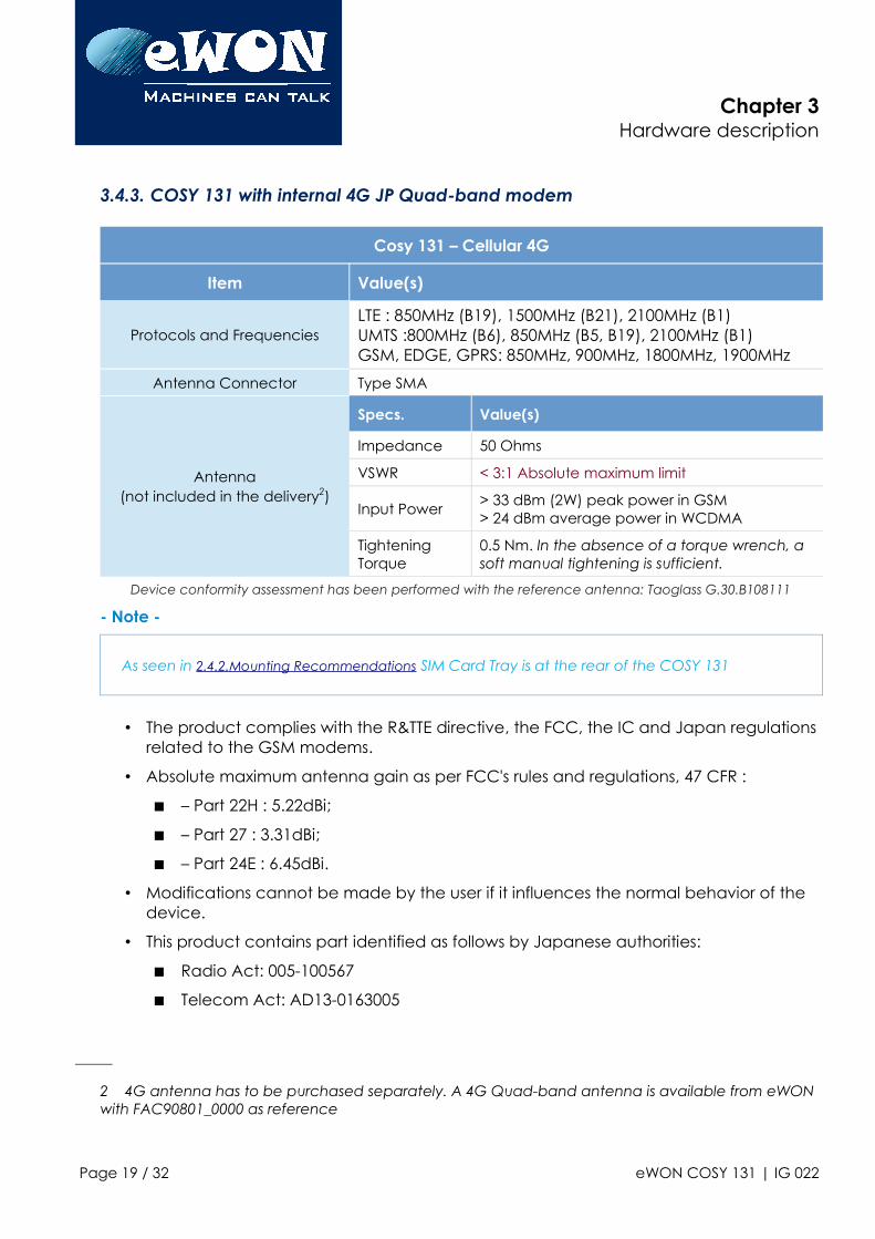
3.4.3. COSY 131 with internal 4G JP Quad-band modem
Cosy 131 – Cellular 4G
Item Value(s)
Protocols and FrequenciesLTE : 850MHz (B19), 1500MHz (B21), 2100MHz (B1) UMTS :800MHz (B6), 850MHz (B5, B19), 2100MHz (B1) GSM, EDGE, GPRS: 850MHz, 900MHz, 1800MHz, 1900MHz
Antenna Connector Type SMA
Antenna(not included in the delivery2)
Specs. Value(s)
Impedance 50 Ohms
VSWR < 3:1 Absolute maximum limit
Input Power> 33 dBm (2W) peak power in GSM> 24 dBm average power in WCDMA
Tightening Torque
0.5 Nm. In the absence of a torque wrench, a soft manual tightening is sufficient.
Device conformity assessment has been performed with the reference antenna: Taoglass G.30.B108111
- Note -
As seen in 2.4.2.Mounting Recommendations SIM Card Tray is at the rear of the COSY 131
• The product complies with the R&TTE directive, the FCC, the IC and Japan regulations related to the GSM modems.
• Absolute maximum antenna gain as per FCC's rules and regulations, 47 CFR :
– Part 22H : 5.22dBi;
– Part 27 : 3.31dBi;
– Part 24E : 6.45dBi.
• Modifications cannot be made by the user if it influences the normal behavior of the device.
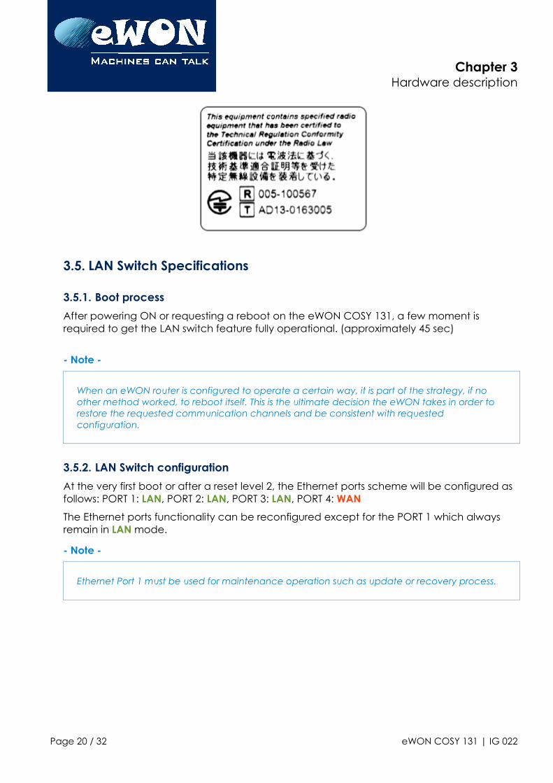
• This product contains part identified as follows by Japanese authorities:
Radio Act: 005-100567
Telecom Act: AD13-0163005
2 4G antenna has to be purchased separately. A 4G Quad-band antenna is available from eWON with FAC90801_0000 as reference
Page 19 / 32 eWON COSY 131 | IG 022
Chapter 3Hardware description
3.5. LAN Switch Specifications
3.5.1. Boot process
After powering ON or requesting a reboot on the eWON COSY 131, a few moment is required to get the LAN switch feature fully operational. (approximately 45 sec)
- Note -
When an eWON router is configured to operate a certain way, it is part of the strategy, if no other method worked, to reboot itself. This is the ultimate decision the eWON takes in order to restore the requested communication channels and be consistent with requested configuration.
3.5.2. LAN Switch configuration
At the very first boot or after a reset level 2, the Ethernet ports scheme will be configured as follows: PORT 1: LAN, PORT 2: LAN, PORT 3: LAN, PORT 4: WAN
The Ethernet ports functionality can be reconfigured except for the PORT 1 which always remain in LAN mode.
- Note -
Ethernet Port 1 must be used for maintenance operation such as update or recovery process.
Page 20 / 32 eWON COSY 131 | IG 022
Chapter 4COSY IP Address & Access to the Web
Configuration
4. COSY IP Address & Access to the Web Configuration
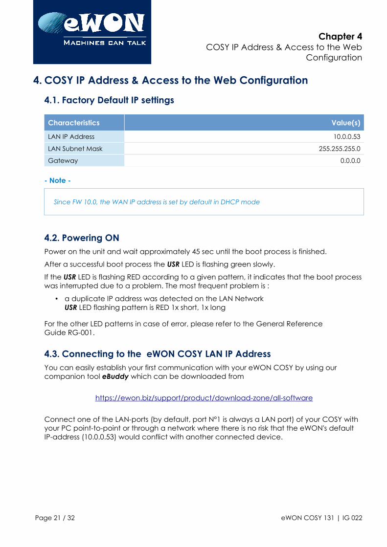
4.1. Factory Default IP settings
Characteristics Value(s)
LAN IP Address 10.0.0.53
LAN Subnet Mask 255.255.255.0
Gateway 0.0.0.0
- Note -
Since FW 10.0, the WAN IP address is set by default in DHCP mode
4.2. Powering ONPower on the unit and wait approximately 45 sec until the boot process is finished.
After a successful boot process the USR LED is flashing green slowly.
If the USR LED is flashing RED according to a given pattern, it indicates that the boot process was interrupted due to a problem. The most frequent problem is :
• a duplicate IP address was detected on the LAN Network USR LED flashing pattern is RED 1x short, 1x long
For the other LED patterns in case of error, please refer to the General Reference Guide RG-001.
4.3. Connecting to the eWON COSY LAN IP AddressYou can easily establish your first communication with your eWON COSY by using our companion tool eBuddy which can be downloaded from
https://ewon.biz/support/product/download-zone/all-software
Connect one of the LAN-ports (by default, port N°1 is always a LAN port) of your COSY with your PC point-to-point or through a network where there is no risk that the eWON's default IP-address (10.0.0.53) would conflict with another connected device.
Page 21 / 32 eWON COSY 131 | IG 022
Chapter 4COSY IP Address & Access to the Web
Configuration
4.4. eWON COSY's Web Interface
Connect your PC to one of the LAN ports of the eWON COSY.
Open your Internet browser and access the eWON COSY Web server by typing the LAN IP address in the URL field(the default address is http://10.0.0.53).
Or use the eBuddy application to easily access to the eWON COSY
- Note -
Get-started with eBuddy and configure your eWON: AUG-065: Reach an eWON with a suitable IP address using eBuddy
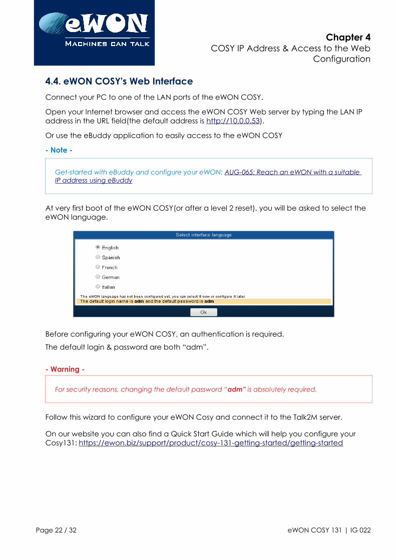
At very first boot of the eWON COSY(or after a level 2 reset), you will be asked to select the eWON language.
Before configuring your eWON COSY, an authentication is required.
The default login & password are both “adm”.
- Warning -
For security reasons, changing the default password “adm” is absolutely required.
Follow this wizard to configure your eWON Cosy and connect it to the Talk2M server.
On our website you can also find a Quick Start Guide which will help you configure your Cosy131: https://ewon.biz/support/product/cosy-131-getting-started/getting-started
Page 22 / 32 eWON COSY 131 | IG 022
Chapter 5Troubleshooting
5. Troubleshooting
5.1. Normal Boot ProcessThe normal boot process of the eWON COSY takes approximately 25 seconds to complete. During this process, all LEDs are first shortly ON (except BI1) then only the PWR LED stays solid green.
As soon as the boot process is finished and the unit is ready to be used, the USR LED flashes GREEN slowly whereas others might be solid green (if you are connected to Internet, Talk2M,...).
5.2. Resetting the eWON COSY 131
The reset button B1 is located on the front of the COSY unit (see in 3.3.1.Front). The reset function of this button is active only if pressed while powering on.
The eWON COSY features two levels of reset:
5.2.1. First Level Reset (user reset)
The first level reset is a selective one that erases the « user files » part and the system settings.This type of reset does not alter the communication parameters of the eWON COSY.
How to perform a first level reset?
• Power the unit OFF.
• While powering it ON, press & maintain the reset button.The LED labeled BI1 turns ON.
• Keep the reset button pressed for approximately 30 seconds until the USR LED flashes RED 1x per second. If you don't release at that specific moment, you will perform a second level reset phase.The LED labeled BI1 turns OFF.
• Wait approximately 30 secs until the reset process is completed.
• The eWON restarts automatically and the unit is ready to be used, the USR LED flashes GREEN slowly.
5.2.2. Second Level Reset (factory reset)
This second level reset restores the eWON to its factory settings. This operation consists in 3 steps:
• Formats the entire non volatile memory, including all COM parameters and IP addresses
• Full hardware auto-test with result shown by the USR LED
Page 23 / 32 eWON COSY 131 | IG 022
Chapter 5Troubleshooting
• Return to ex-factory configuration (default config)
How to perform a second level reset?
• Power the unit OFF.
• While powering it ON, press & maintain the reset button.The LED labeled BI1 turns ON.
• Keep the reset button pressed for approximately 35 seconds until the USR LED remains RED steady.
• When this state is reached, release the button. The LED labeled BI1 turns OFF.
• It takes no longer than 2 seconds to complete.
• Check if the auto test is successful, the USR LED flashes RED with a pattern of 200ms ONand 1,5 sec OFF3. The eWON COSY does NOT restart in normal mode by itself and remains running in this diagnostic mode.
• You have to power the eWON COSY OFF and ON again to reboot the unit in normal mode. As described before, the eWON returns to its default COM parameters and factory IP addresses (such as LAN 10.0.0.53) after this level 2 reset is performed.
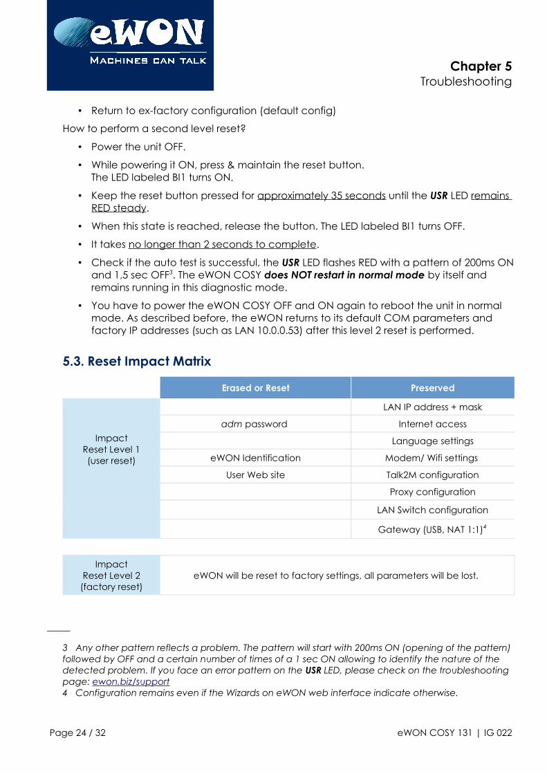
5.3. Reset Impact Matrix
Erased or Reset Preserved
ImpactReset Level 1(user reset)
LAN IP address + mask
adm password Internet access
Language settings
eWON Identification Modem/ Wifi settings
User Web site Talk2M configuration
Proxy configuration
LAN Switch configuration
Gateway (USB, NAT 1:1)4
ImpactReset Level 2
(factory reset)eWON will be reset to factory settings, all parameters will be lost.
3 Any other pattern reflects a problem. The pattern will start with 200ms ON (opening of the pattern)followed by OFF and a certain number of times of a 1 sec ON allowing to identify the nature of the detected problem. If you face an error pattern on the USR LED, please check on the troubleshooting page: ewon.biz/support4 Configuration remains even if the Wizards on eWON web interface indicate otherwise.
Page 24 / 32 eWON COSY 131 | IG 022
Appendix A - Connector Pinout & RelatedSpecifications
Appendix A - Connector Pinout & Related Specifications
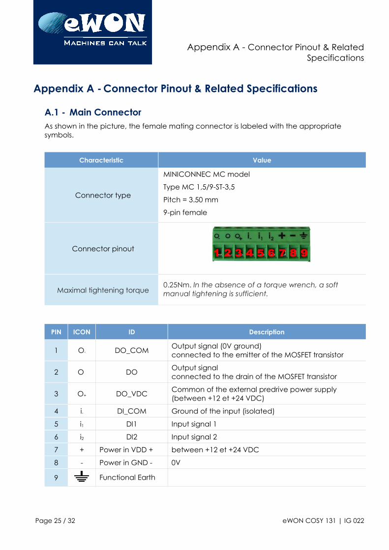
A.1 - Main ConnectorAs shown in the picture, the female mating connector is labeled with the appropriate symbols.
Characteristic Value
Connector type
MINICONNEC MC model
Type MC 1,5/9-ST-3,5
Pitch = 3.50 mm
9-pin female
Connector pinout
Maximal tightening torque0.25Nm. In the absence of a torque wrench, a soft manual tightening is sufficient.
PIN ICON ID Description
1 O- DO_COMOutput signal (0V ground)connected to the emitter of the MOSFET transistor
2 O DOOutput signalconnected to the drain of the MOSFET transistor
3 O+ DO_VDCCommon of the external predrive power supply (between +12 et +24 VDC)
4 i- DI_COM Ground of the input (isolated)
5 i1 DI1 Input signal 1
6 i2 DI2 Input signal 2
7 + Power in VDD + between +12 et +24 VDC
8 - Power in GND - 0V
9 Functional Earth
Page 25 / 32 eWON COSY 131 | IG 022
Appendix A - Connector Pinout & RelatedSpecifications
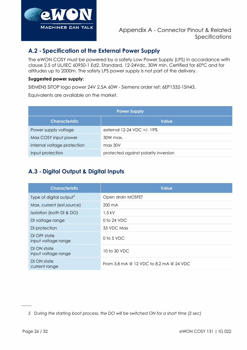
A.2 - Specification of the External Power SupplyThe eWON COSY must be powered by a safety Low Power Supply (LPS) in accordance with clause 2.5 of UL/IEC 60950-1 Ed2. Standard, 12-24Vdc, 30W min. Certified for 60°C and for altitudes up to 2000m. The safety LPS power supply is not part of the delivery.
Suggested power supply:
SIEMENS SITOP logo power 24V 2.5A 60W - Siemens order ref: 6EP1332-1SH43.
Equivalents are available on the market.
Power Supply
Characteristic Value
Power supply voltage external 12-24 VDC +/- 19%
Max COSY input power 30W max.
Internal voltage protection max 30V
Input protection protected against polarity inversion
A.3 - Digital Output & Digital Inputs
Characteristic Value
Type of digital output5 Open drain MOSFET
Max. current (ext,source) 200 mA
Isolation (both DI & DO) 1,5 kV
DI voltage range 0 to 24 VDC
DI protection 33 VDC Max
DI OFF stateinput voltage range
0 to 5 VDC
DI ON stateinput voltage range
10 to 30 VDC
DI ON statecurrent range
From 3,8 mA @ 12 VDC to 8,2 mA @ 24 VDC
5 During the starting boot process, the DO will be switched ON for a short time (2 sec)
Page 26 / 32 eWON COSY 131 | IG 022

Appendix A - Connector Pinout & RelatedSpecifications
Page 27 / 32 eWON COSY 131 | IG 022
Appendix A - Connector Pinout & RelatedSpecifications
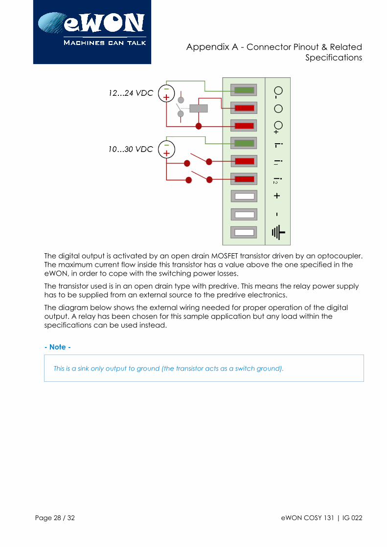
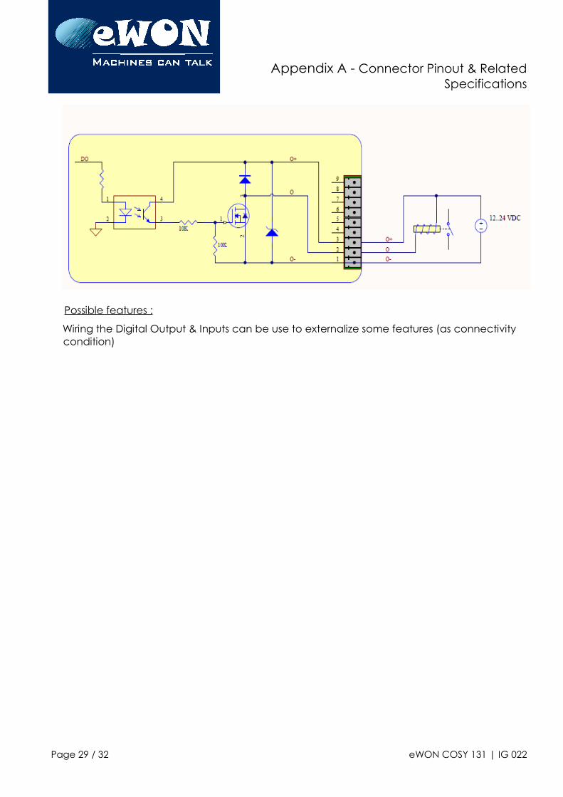
The digital output is activated by an open drain MOSFET transistor driven by an optocoupler.The maximum current flow inside this transistor has a value above the one specified in the eWON, in order to cope with the switching power losses.
The transistor used is in an open drain type with predrive. This means the relay power supply has to be supplied from an external source to the predrive electronics.
The diagram below shows the external wiring needed for proper operation of the digital output. A relay has been chosen for this sample application but any load within the specifications can be used instead.
- Note -
This is a sink only output to ground (the transistor acts as a switch ground).
Page 28 / 32 eWON COSY 131 | IG 022
Appendix A - Connector Pinout & RelatedSpecifications
Possible features :
Wiring the Digital Output & Inputs can be use to externalize some features (as connectivity condition)
Page 29 / 32 eWON COSY 131 | IG 022
Appendix A - Connector Pinout & RelatedSpecifications
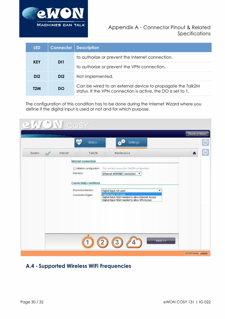
LED Connector Description
KEY DI1to authorize or prevent the Internet connection.
to authorize or prevent the VPN connection.
DI2 DI2 Not implemented.
T2M DOCan be wired to an external device to propagate the Talk2M status. If the VPN connection is active, the DO is set to 1.
The configuration of this condition has to be done during the Internet Wizard where you define if the digital input is used or not and for which purpose.
A.4 - Supported Wireless WiFi Frequencies
Page 30 / 32 eWON COSY 131 | IG 022
Appendix A - Connector Pinout & RelatedSpecifications
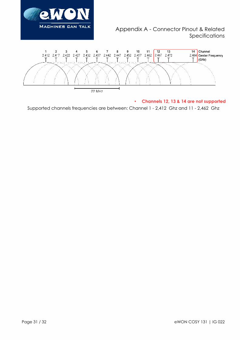
• Channels 12, 13 & 14 are not supported
Supported channels frequencies are between: Channel 1 - 2,412 Ghz and 11 - 2,462 Ghz
Page 31 / 32 eWON COSY 131 | IG 022
Revision
Revision
Revision History
Revision Date Description
1.0 22/01/2015 Original Document
1.1 04/02/2015 Pictures modifications
1.2 27/04/2015 WiFi & DI/DO Updates (3.4.1 A.3, A.4)
1.3 30/06/2015 Added Cabling rules (#2.4.3.Cabling rules)
1.4 17/11/2015 Added section 3.5: LAN Switch Specifications
1.5 11/01/2016 Modified DO Diagram
1.6 14/06/2016 Added COSY EC6133E + Digital I/O update
1.7 27/07/2016 Update of Legal References
Document build number: 19
Note concerning the warranty and the rights of ownership:
The information contained in this document is subject to modification without notice. Check http://support.ewon.biz for the latest documents releases.
The vendor and the authors of this manual are not liable for the errors it may contain, nor for their eventual consequences.
No liability or warranty, explicit or implicit, is made concerning the quality, the accuracy and the correctness of the information contained in this document. In no case the manufacturer's responsibility could be called for direct, indirect, accidental or other damage occurring from any defect of the product of errors coming from this document.
The product names are mentioned in this manual for information purposes only. The trade marks and the product names or marks contained in this document are the property of their respective owners.
This document contains materials protected by the International Copyright Laws. All reproduction rights are reserved. No part of this handbook can be reproduced, transmitted or copied in any way without written consent from the manufacturer and/or the authors of this handbook.
eWON sa
Page 32 / 32 eWON COSY 131 | IG 022
comcfg.txt Parameters
1. Purpose This document lists the comcfg.txt parameters. Some parameters listed are not relevant to certain eWON types and may hence appear neither in the corresponding comcfg.txt file nor on the interface.
For practical reasons, the data is looked at from two different perspectives. In chapter 2 we present the parameters as they appear in the comcfg.txt file with description, default and acceptable values. In chapter 3 we show how you can access these parameters from the user interface.
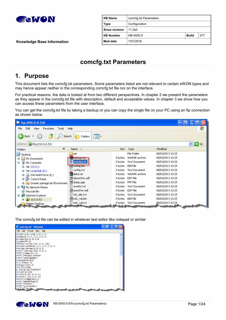
You can get the comcfg.txt file by taking a backup or you can copy the single file on your PC using an ftp connection as shown below.
The comcfg.txt file can be edited in whatever text editor like notepad or similar
KB-0050-0-EN-(comcfg.txt Parameters) Page 1/24
KB Name comcfg.txt Parameters
Type Configuration
Since revision 11.2s0
KB Number KB-0050-0 Build 277
Knowledge Base Information Mod date 7/07/2016
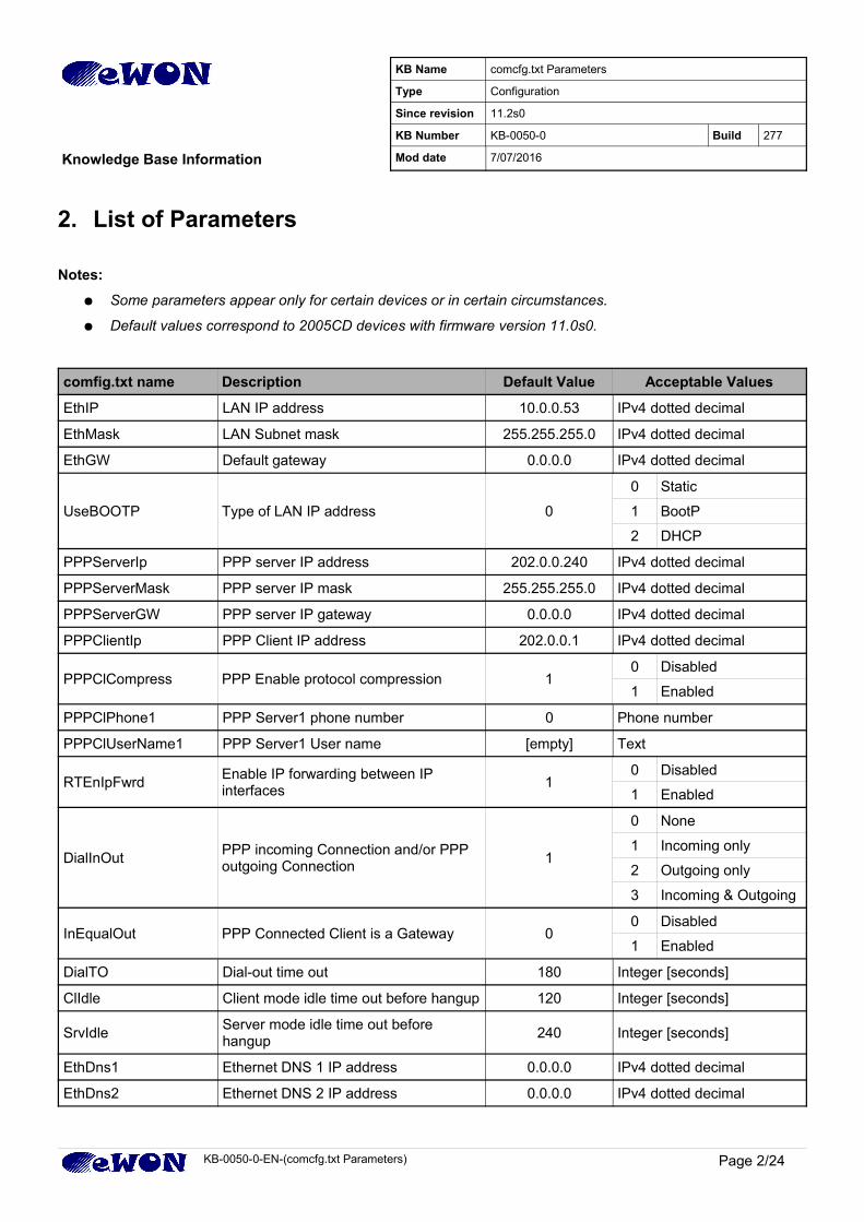
2. List of Parameters
Notes:
● Some parameters appear only for certain devices or in certain circumstances.
● Default values correspond to 2005CD devices with firmware version 11.0s0.
comfig.txt name Description Default Value Acceptable Values
EthIP LAN IP address 10.0.0.53 IPv4 dotted decimal
EthMask LAN Subnet mask 255.255.255.0 IPv4 dotted decimal
EthGW Default gateway 0.0.0.0 IPv4 dotted decimal
UseBOOTP Type of LAN IP address 0
0 Static
1 BootP
2 DHCP
PPPServerIp PPP server IP address 202.0.0.240 IPv4 dotted decimal
PPPServerMask PPP server IP mask 255.255.255.0 IPv4 dotted decimal
PPPServerGW PPP server IP gateway 0.0.0.0 IPv4 dotted decimal
PPPClientIp PPP Client IP address 202.0.0.1 IPv4 dotted decimal
PPPClCompress PPP Enable protocol compression 10 Disabled
1 Enabled
PPPClPhone1 PPP Server1 phone number 0 Phone number
PPPClUserName1 PPP Server1 User name [empty] Text
RTEnIpFwrdEnable IP forwarding between IP interfaces
10 Disabled
1 Enabled
DialInOutPPP incoming Connection and/or PPP outgoing Connection
1
0 None
1 Incoming only
2 Outgoing only
3 Incoming & Outgoing
InEqualOut PPP Connected Client is a Gateway 00 Disabled
1 Enabled
DialTO Dial-out time out 180 Integer [seconds]
ClIdle Client mode idle time out before hangup 120 Integer [seconds]
SrvIdleServer mode idle time out before hangup
240 Integer [seconds]
EthDns1 Ethernet DNS 1 IP address 0.0.0.0 IPv4 dotted decimal
EthDns2 Ethernet DNS 2 IP address 0.0.0.0 IPv4 dotted decimal
KB-0050-0-EN-(comcfg.txt Parameters) Page 2/24
KB Name comcfg.txt Parameters
Type Configuration
Since revision 11.2s0
KB Number KB-0050-0 Build 277
Knowledge Base Information Mod date 7/07/2016
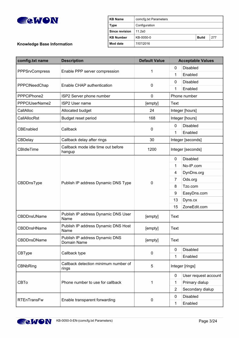
comfig.txt name Description Default Value Acceptable Values
PPPSrvCompress Enable PPP server compression 10 Disabled
1 Enabled
PPPClNeedChap Enable CHAP authentication 00 Disabled
1 Enabled
PPPClPhone2 ISP2 Server phone number 0 Phone number
PPPClUserName2 ISP2 User name [empty] Text
CallAlloc Allocated budget 24 Integer [hours]
CallAllocRst Budget reset period 168 Integer [hours]
CBEnabled Callback 00 Disabled
1 Enabled
CBDelay Callback delay after rings 30 Integer [seconds]
CBIdleTimeCallback mode idle time out before hangup
1200 Integer [seconds]
CBDDnsType Publish IP address Dynamic DNS Type 0
0 Disabled
1 No-IP.com
4 DynDns.org
7 Ods.org
8 Tzo.com
9 EasyDns.com
13 Dyns.cx
15 ZoneEdit.com
CBDDnsUNamePublish IP address Dynamic DNS User Name
[empty] Text
CBDDnsHNamePublish IP address Dynamic DNS Host Name
[empty] Text
CBDDnsDNamePublish IP address Dynamic DNS Domain Name
[empty] Text
CBType Callback type 00 Disabled
1 Enabled
CBNbRingCallback detection minimum number of rings
5 Integer [rings]
CBTo Phone number to use for callback 1
0 User request account
1 Primary dialup
2 Secondary dialup
RTEnTransFw Enable transparent forwarding 00 Disabled
1 Enabled
KB-0050-0-EN-(comcfg.txt Parameters) Page 3/24
KB Name comcfg.txt Parameters
Type Configuration
Since revision 11.2s0
KB Number KB-0050-0 Build 277
Knowledge Base Information Mod date 7/07/2016
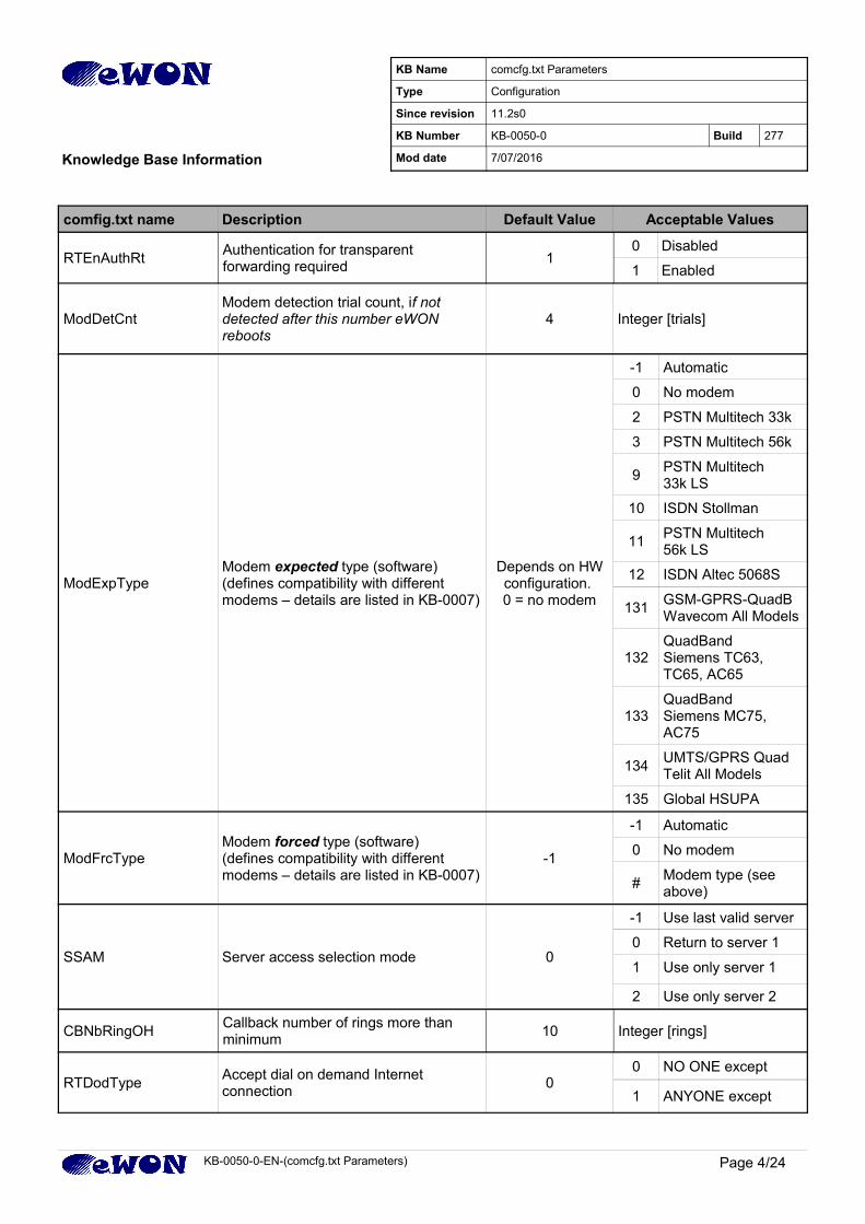
comfig.txt name Description Default Value Acceptable Values
RTEnAuthRtAuthentication for transparent forwarding required
10 Disabled
1 Enabled
ModDetCntModem detection trial count, if not detected after this number eWON reboots
4 Integer [trials]
ModExpTypeModem expected type (software)(defines compatibility with different modems – details are listed in KB-0007)
Depends on HWconfiguration. 0 = no modem
-1 Automatic
0 No modem
2 PSTN Multitech 33k
3 PSTN Multitech 56k
9PSTN Multitech 33k LS
10 ISDN Stollman
11PSTN Multitech 56k LS
12 ISDN Altec 5068S
131GSM-GPRS-QuadBWavecom All Models
132QuadBandSiemens TC63, TC65, AC65
133QuadBandSiemens MC75, AC75
134UMTS/GPRS QuadTelit All Models
135 Global HSUPA
ModFrcTypeModem forced type (software)(defines compatibility with different modems – details are listed in KB-0007)
-1
-1 Automatic
0 No modem
#Modem type (see above)
SSAM Server access selection mode 0
-1 Use last valid server
0 Return to server 1
1 Use only server 1
2 Use only server 2
CBNbRingOHCallback number of rings more than minimum
10 Integer [rings]
RTDodTypeAccept dial on demand Internet connection
00 NO ONE except
1 ANYONE except
KB-0050-0-EN-(comcfg.txt Parameters) Page 4/24
KB Name comcfg.txt Parameters
Type Configuration
Since revision 11.2s0
KB Number KB-0050-0 Build 277
Knowledge Base Information Mod date 7/07/2016
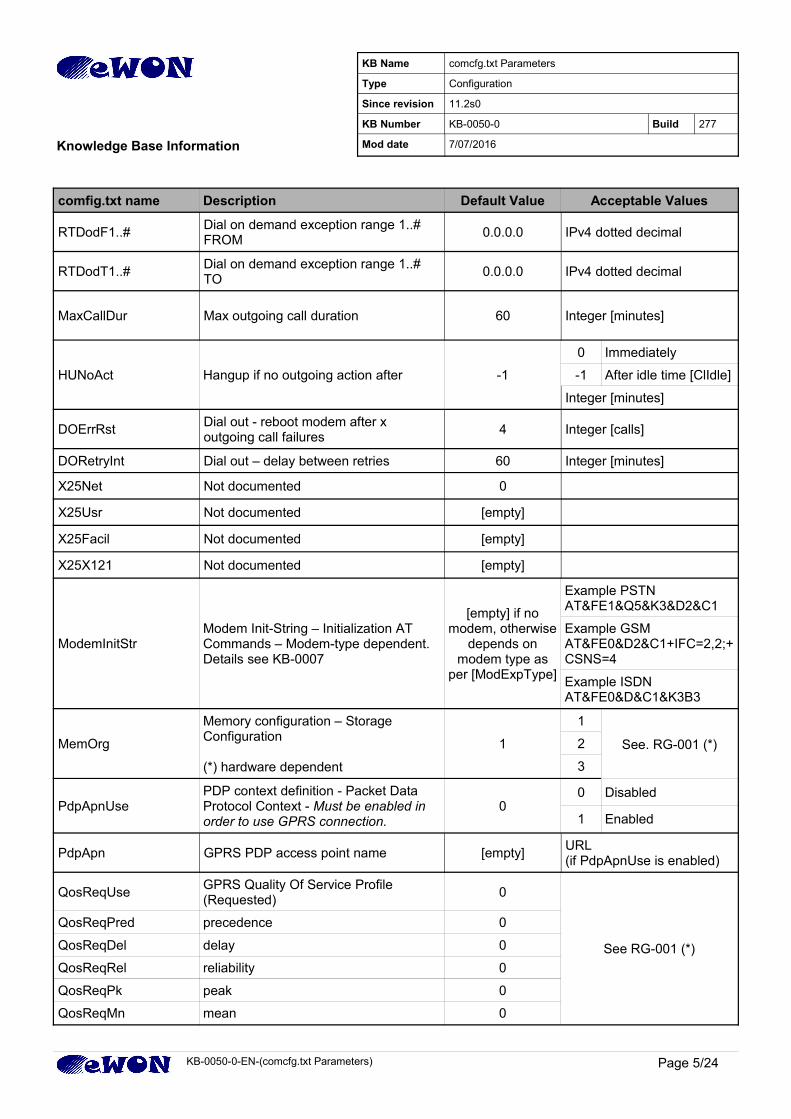
comfig.txt name Description Default Value Acceptable Values
RTDodF1..#Dial on demand exception range 1..# FROM
0.0.0.0 IPv4 dotted decimal
RTDodT1..#Dial on demand exception range 1..# TO
0.0.0.0 IPv4 dotted decimal
MaxCallDur Max outgoing call duration 60 Integer [minutes]
HUNoAct Hangup if no outgoing action after -1
0 Immediately
-1 After idle time [ClIdle]
Integer [minutes]
DOErrRstDial out - reboot modem after x outgoing call failures
4 Integer [calls]
DORetryInt Dial out – delay between retries 60 Integer [minutes]
X25Net Not documented 0
X25Usr Not documented [empty]
X25Facil Not documented [empty]
X25X121 Not documented [empty]
ModemInitStrModem Init-String – Initialization AT Commands – Modem-type dependent.Details see KB-0007
[empty] if nomodem, otherwise
depends onmodem type as
per [ModExpType]
Example PSTNAT&FE1&Q5&K3&D2&C1
Example GSMAT&FE0&D2&C1+IFC=2,2;+CSNS=4
Example ISDNAT&FE0&D&C1&K3B3
MemOrg
Memory configuration – Storage Configuration
(*) hardware dependent
1
1
See. RG-001 (*)2
3
PdpApnUsePDP context definition - Packet Data Protocol Context - Must be enabled in order to use GPRS connection.
00 Disabled
1 Enabled
PdpApn GPRS PDP access point name [empty]URL (if PdpApnUse is enabled)
QosReqUseGPRS Quality Of Service Profile (Requested)
0
See RG-001 (*)
QosReqPred precedence 0
QosReqDel delay 0
QosReqRel reliability 0
QosReqPk peak 0
QosReqMn mean 0
KB-0050-0-EN-(comcfg.txt Parameters) Page 5/24
KB Name comcfg.txt Parameters
Type Configuration
Since revision 11.2s0
KB Number KB-0050-0 Build 277
Knowledge Base Information Mod date 7/07/2016
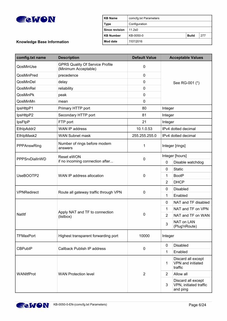
comfig.txt name Description Default Value Acceptable Values
QosMinUseGPRS Quality Of Service Profile (Minimum Acceptable)
0
See RG-001 (*)
QosMinPred precedence 0
QosMinDel delay 0
QosMinRel reliability 0
QosMinPk peak 0
QosMinMn mean 0
IpsHttpP1 Primary HTTP port 80 Integer
IpsHttpP2 Secondary HTTP port 81 Integer
IpsFtpP FTP port 21 Integer
EthIpAddr2 WAN IP address 10.1.0.53 IPv4 dotted decimal
EthIpMask2 WAN Subnet mask 255.255.255.0 IPv4 dotted decimal
PPPAnswRingNumber of rings before modem answers
1 Integer [rings]
PPPSrvDialInWDReset eWON if no incoming connection after...
0Integer [hours]
0 Disable watchdog
UseBOOTP2 WAN IP address allocation 0
0 Static
1 BootP
2 DHCP
VPNRedirect Route all gateway traffic through VPN 00 Disabled
1 Enabled
NatItfApply NAT and TF to connection (listbox)
0
0 NAT and TF disabled
1 NAT and TF on VPN
2 NAT and TF on WAN
3NAT on LAN (Plug'nRoute)
TFMaxPort Highest transparent forwarding port 10000 Integer
CBPubIP Callback Publish IP address 00 Disabled
1 Enabled
WANItfProt WAN Protection level 2
1Discard all except VPN and initiated traffic
2 Allow all
3Discard all except VPN, initiated traffic and ping
KB-0050-0-EN-(comcfg.txt Parameters) Page 6/24
KB Name comcfg.txt Parameters
Type Configuration
Since revision 11.2s0
KB Number KB-0050-0 Build 277
Knowledge Base Information Mod date 7/07/2016
comfig.txt name Description Default Value Acceptable Values
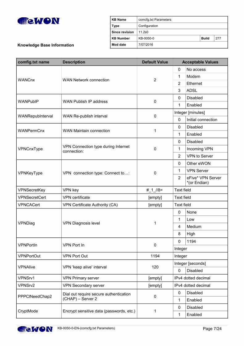
WANCnx WAN Network connection 2
0 No access
1 Modem
2 Ethernet
3 ADSL
WANPubIP WAN Publish IP address 00 Disabled
1 Enabled
WANRepubInterval WAN Re-publish interval 0Integer [minutes]
0 Initial connection
WANPermCnx WAN Maintain connection 10 Disabled
1 Enabled
VPNCnxTypeVPN Connection type during Internet connection:
0
0 Disabled
1 Incoming VPN
2 VPN to Server
VPNKeyType VPN connection type: Connect to…: 0
0 Other eWON
1 VPN Server
2 eFive* VPN Server*(or Endian)
VPNSecretKey VPN key #_1_//8= Text field
VPNSecretCert VPN certificate [empty] Text field
VPNCACert VPN Certificate Authority (CA) [empty] Text field
VPNDiag VPN Diagnosis level 1
0 None
1 Low
4 Medium
8 High
VPNPortIn VPN Port In 00 1194
Integer
VPNPortOut VPN Port Out 1194 Integer
VPNAlive VPN 'keep alive' interval 120Integer [seconds]
0 Disabled
VPNSrv1 VPN Primary server [empty] IPv4 dotted decimal
VPNSrv2 VPN Secondary server [empty] IPv4 dotted decimal
PPPClNeedChap2Dial out require secure authentication (CHAP) – Server 2
00 Disabled
1 Enabled
CryptMode Encrypt sensitive data (passwords, etc.) 10 Disabled
1 Enabled
KB-0050-0-EN-(comcfg.txt Parameters) Page 7/24
KB Name comcfg.txt Parameters
Type Configuration
Since revision 11.2s0
KB Number KB-0050-0 Build 277
Knowledge Base Information Mod date 7/07/2016
comfig.txt name Description Default Value Acceptable Values
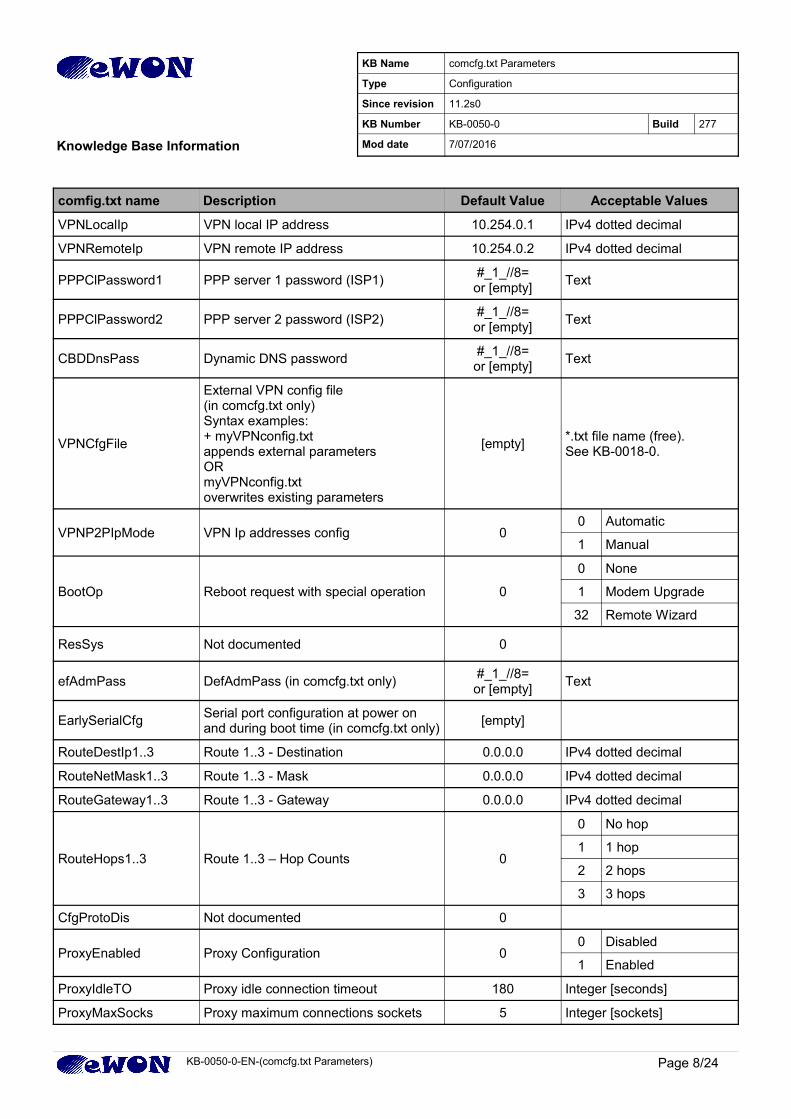
VPNLocalIp VPN local IP address 10.254.0.1 IPv4 dotted decimal
VPNRemoteIp VPN remote IP address 10.254.0.2 IPv4 dotted decimal
PPPClPassword1 PPP server 1 password (ISP1)#_1_//8=or [empty]
Text
PPPClPassword2 PPP server 2 password (ISP2)#_1_//8=or [empty]
Text
CBDDnsPass Dynamic DNS password#_1_//8=or [empty]
Text
VPNCfgFile
External VPN config file(in comcfg.txt only)Syntax examples: + myVPNconfig.txt appends external parametersORmyVPNconfig.txtoverwrites existing parameters
[empty]*.txt file name (free). See KB-0018-0.
VPNP2PIpMode VPN Ip addresses config 00 Automatic
1 Manual
BootOp Reboot request with special operation 0
0 None
1 Modem Upgrade
32 Remote Wizard
ResSys Not documented 0
efAdmPass DefAdmPass (in comcfg.txt only)#_1_//8=or [empty]
Text
EarlySerialCfgSerial port configuration at power on and during boot time (in comcfg.txt only)
[empty]
RouteDestIp1..3 Route 1..3 - Destination 0.0.0.0 IPv4 dotted decimal
RouteNetMask1..3 Route 1..3 - Mask 0.0.0.0 IPv4 dotted decimal
RouteGateway1..3 Route 1..3 - Gateway 0.0.0.0 IPv4 dotted decimal
RouteHops1..3 Route 1..3 – Hop Counts 0
0 No hop
1 1 hop
2 2 hops
3 3 hops
CfgProtoDis Not documented 0
ProxyEnabled Proxy Configuration 00 Disabled
1 Enabled
ProxyIdleTO Proxy idle connection timeout 180 Integer [seconds]
ProxyMaxSocks Proxy maximum connections sockets 5 Integer [sockets]
KB-0050-0-EN-(comcfg.txt Parameters) Page 8/24
KB Name comcfg.txt Parameters
Type Configuration
Since revision 11.2s0
KB Number KB-0050-0 Build 277
Knowledge Base Information Mod date 7/07/2016
comfig.txt name Description Default Value Acceptable Values
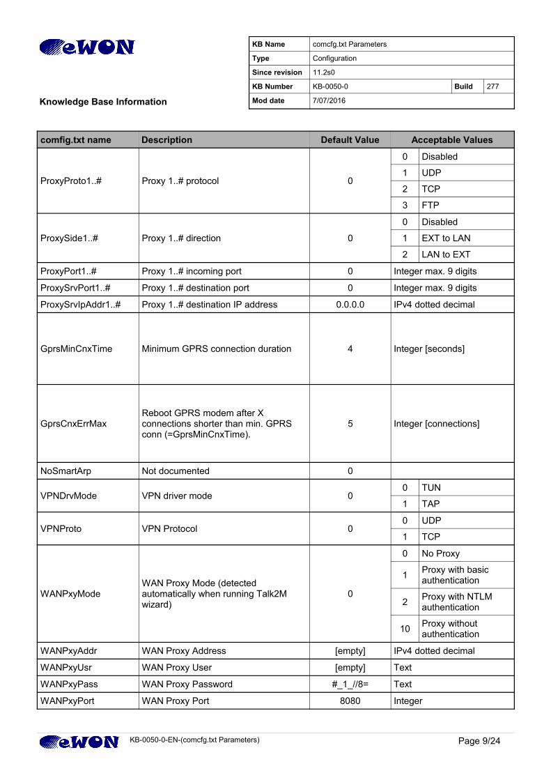
ProxyProto1..# Proxy 1..# protocol 0
0 Disabled
1 UDP
2 TCP
3 FTP
ProxySide1..# Proxy 1..# direction 0
0 Disabled
1 EXT to LAN
2 LAN to EXT
ProxyPort1..# Proxy 1..# incoming port 0 Integer max. 9 digits
ProxySrvPort1..# Proxy 1..# destination port 0 Integer max. 9 digits
ProxySrvIpAddr1..# Proxy 1..# destination IP address 0.0.0.0 IPv4 dotted decimal
GprsMinCnxTime Minimum GPRS connection duration 4 Integer [seconds]
GprsCnxErrMaxReboot GPRS modem after X connections shorter than min. GPRS conn (=GprsMinCnxTime).
5 Integer [connections]
NoSmartArp Not documented 0
VPNDrvMode VPN driver mode 00 TUN
1 TAP
VPNProto VPN Protocol 00 UDP
1 TCP
WANPxyModeWAN Proxy Mode (detected automatically when running Talk2M wizard)
0
0 No Proxy
1Proxy with basic authentication
2Proxy with NTLM authentication
10Proxy without authentication
WANPxyAddr WAN Proxy Address [empty] IPv4 dotted decimal
WANPxyUsr WAN Proxy User [empty] Text
WANPxyPass WAN Proxy Password #_1_//8= Text
WANPxyPort WAN Proxy Port 8080 Integer
KB-0050-0-EN-(comcfg.txt Parameters) Page 9/24
KB Name comcfg.txt Parameters
Type Configuration
Since revision 11.2s0
KB Number KB-0050-0 Build 277
Knowledge Base Information Mod date 7/07/2016
comfig.txt name Description Default Value Acceptable Values
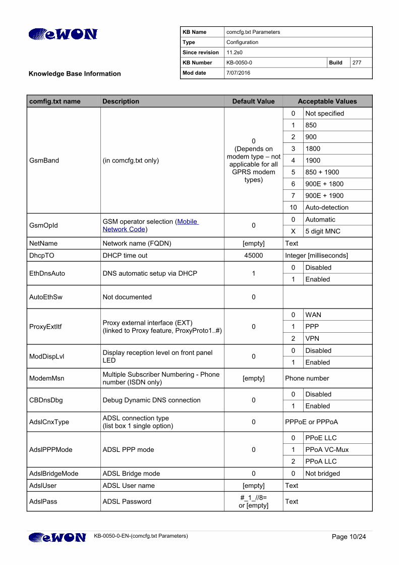
GsmBand (in comcfg.txt only)
0(Depends on
modem type – notapplicable for allGPRS modem
types)
0 Not specified
1 850
2 900
3 1800
4 1900
5 850 + 1900
6 900E + 1800
7 900E + 1900
10 Auto-detection
GsmOpIdGSM operator selection (Mobile Network Code)
00 Automatic
X 5 digit MNC
NetName Network name (FQDN) [empty] Text
DhcpTO DHCP time out 45000 Integer [milliseconds]
EthDnsAuto DNS automatic setup via DHCP 10 Disabled
1 Enabled
AutoEthSw Not documented 0
ProxyExtItfProxy external interface (EXT)(linked to Proxy feature, ProxyProto1..#)
0
0 WAN
1 PPP
2 VPN
ModDispLvlDisplay reception level on front panel LED
00 Disabled
1 Enabled
ModemMsnMultiple Subscriber Numbering - Phone number (ISDN only)
[empty] Phone number
CBDnsDbg Debug Dynamic DNS connection 00 Disabled
1 Enabled
AdslCnxTypeADSL connection type (list box 1 single option)
0 PPPoE or PPPoA
AdslPPPMode ADSL PPP mode 0
0 PPoE LLC
1 PPoA VC-Mux
2 PPoA LLC
AdslBridgeMode ADSL Bridge mode 0 0 Not bridged
AdslUser ADSL User name [empty] Text
AdslPass ADSL Password#_1_//8=or [empty]
Text
KB-0050-0-EN-(comcfg.txt Parameters) Page 10/24
KB Name comcfg.txt Parameters
Type Configuration
Since revision 11.2s0
KB Number KB-0050-0 Build 277
Knowledge Base Information Mod date 7/07/2016
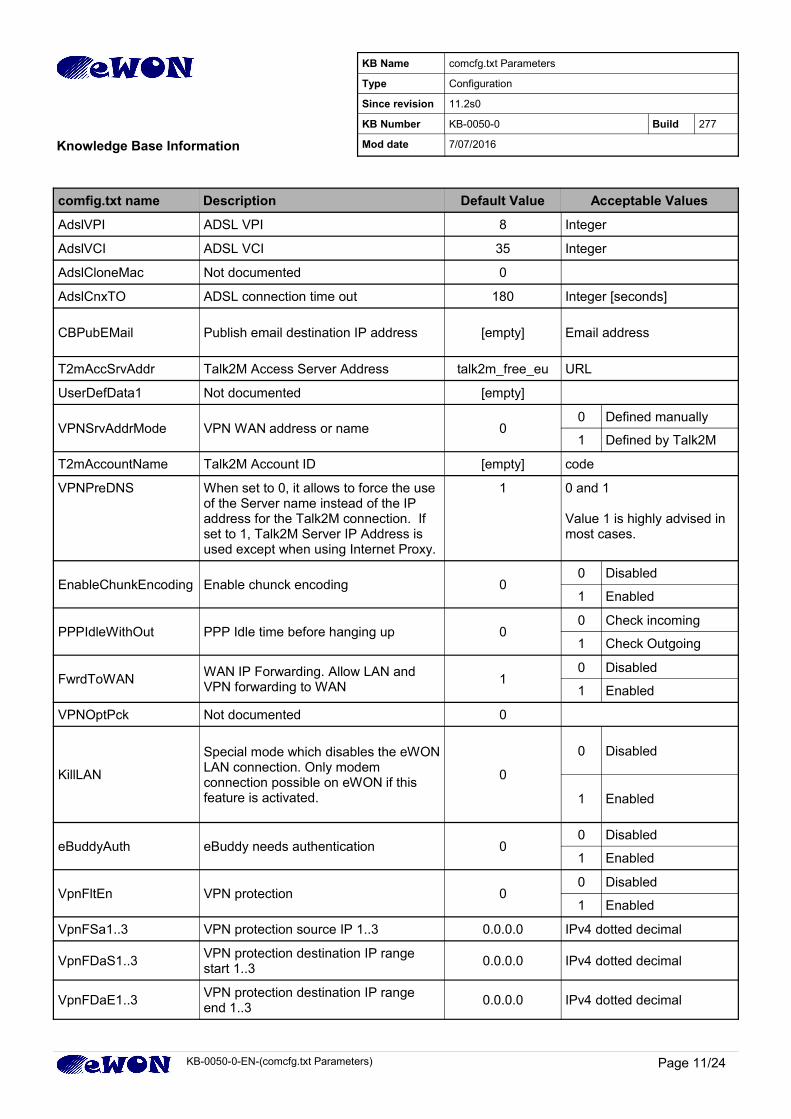
comfig.txt name Description Default Value Acceptable Values
AdslVPI ADSL VPI 8 Integer
AdslVCI ADSL VCI 35 Integer
AdslCloneMac Not documented 0
AdslCnxTO ADSL connection time out 180 Integer [seconds]
CBPubEMail Publish email destination IP address [empty] Email address
T2mAccSrvAddr Talk2M Access Server Address talk2m_free_eu URL
UserDefData1 Not documented [empty]
VPNSrvAddrMode VPN WAN address or name 00 Defined manually
1 Defined by Talk2M
T2mAccountName Talk2M Account ID [empty] code
VPNPreDNS When set to 0, it allows to force the use of the Server name instead of the IP address for the Talk2M connection. If set to 1, Talk2M Server IP Address is used except when using Internet Proxy.
1 0 and 1
Value 1 is highly advised in most cases.
EnableChunkEncoding Enable chunck encoding 00 Disabled
1 Enabled
PPPIdleWithOut PPP Idle time before hanging up 00 Check incoming
1 Check Outgoing
FwrdToWANWAN IP Forwarding. Allow LAN and VPN forwarding to WAN
10 Disabled
1 Enabled
VPNOptPck Not documented 0
KillLAN
Special mode which disables the eWONLAN connection. Only modem connection possible on eWON if this feature is activated.
0
0 Disabled
1 Enabled
eBuddyAuth eBuddy needs authentication 00 Disabled
1 Enabled
VpnFltEn VPN protection 00 Disabled
1 Enabled
VpnFSa1..3 VPN protection source IP 1..3 0.0.0.0 IPv4 dotted decimal
VpnFDaS1..3VPN protection destination IP range start 1..3
0.0.0.0 IPv4 dotted decimal
VpnFDaE1..3VPN protection destination IP range end 1..3
0.0.0.0 IPv4 dotted decimal
KB-0050-0-EN-(comcfg.txt Parameters) Page 11/24
KB Name comcfg.txt Parameters
Type Configuration
Since revision 11.2s0
KB Number KB-0050-0 Build 277
Knowledge Base Information Mod date 7/07/2016
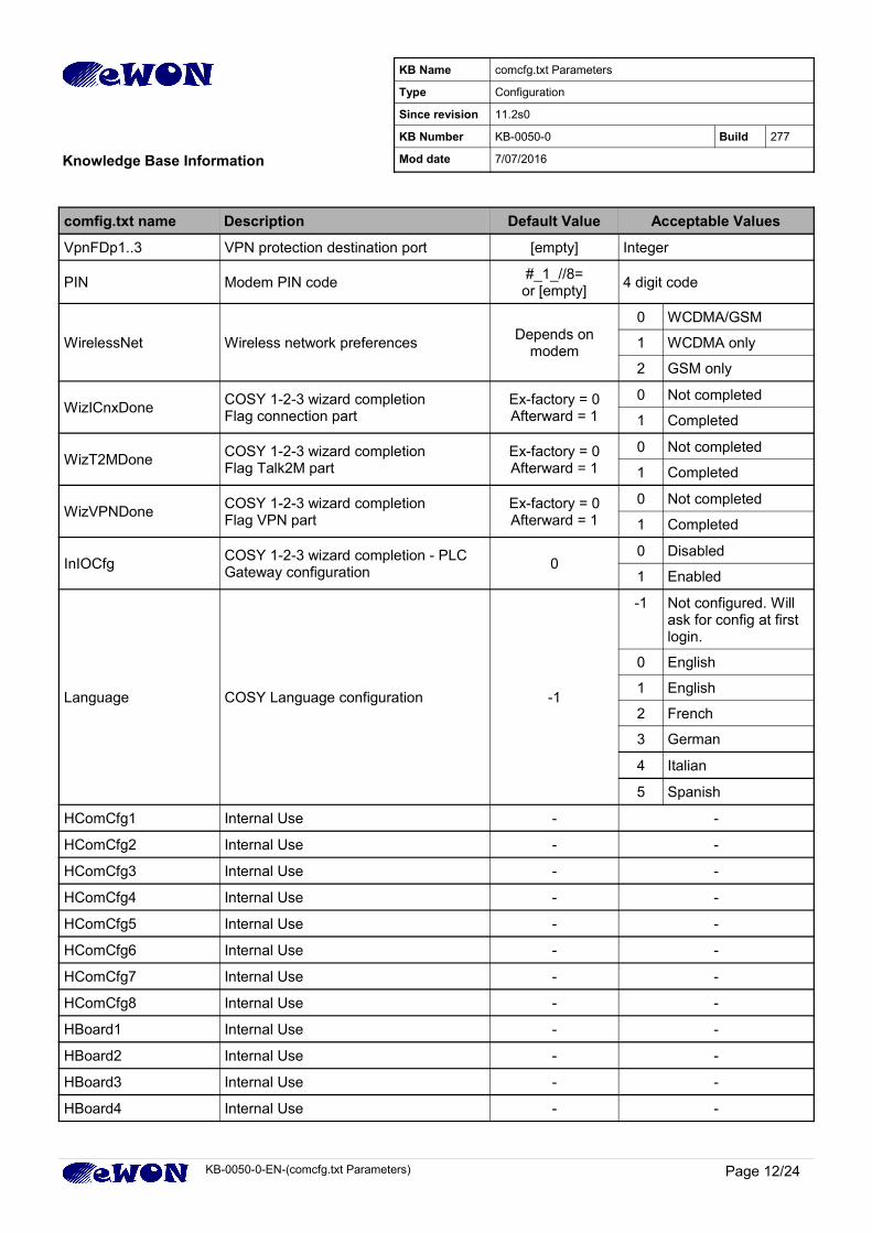
comfig.txt name Description Default Value Acceptable Values
VpnFDp1..3 VPN protection destination port [empty] Integer
PIN Modem PIN code#_1_//8=or [empty]
4 digit code
WirelessNet Wireless network preferencesDepends on
modem
0 WCDMA/GSM
1 WCDMA only
2 GSM only
WizICnxDoneCOSY 1-2-3 wizard completion Flag connection part
Ex-factory = 0Afterward = 1
0 Not completed
1 Completed
WizT2MDoneCOSY 1-2-3 wizard completion Flag Talk2M part
Ex-factory = 0Afterward = 1
0 Not completed
1 Completed
WizVPNDoneCOSY 1-2-3 wizard completion Flag VPN part
Ex-factory = 0Afterward = 1
0 Not completed
1 Completed
InIOCfgCOSY 1-2-3 wizard completion - PLC Gateway configuration
00 Disabled
1 Enabled
Language COSY Language configuration -1
-1 Not configured. Will ask for config at first login.
0 English
1 English
2 French
3 German
4 Italian
5 Spanish
HComCfg1 Internal Use - -
HComCfg2 Internal Use - -
HComCfg3 Internal Use - -
HComCfg4 Internal Use - -
HComCfg5 Internal Use - -
HComCfg6 Internal Use - -
HComCfg7 Internal Use - -
HComCfg8 Internal Use - -
HBoard1 Internal Use - -
HBoard2 Internal Use - -
HBoard3 Internal Use - -
HBoard4 Internal Use - -
KB-0050-0-EN-(comcfg.txt Parameters) Page 12/24
KB Name comcfg.txt Parameters
Type Configuration
Since revision 11.2s0
KB Number KB-0050-0 Build 277
Knowledge Base Information Mod date 7/07/2016
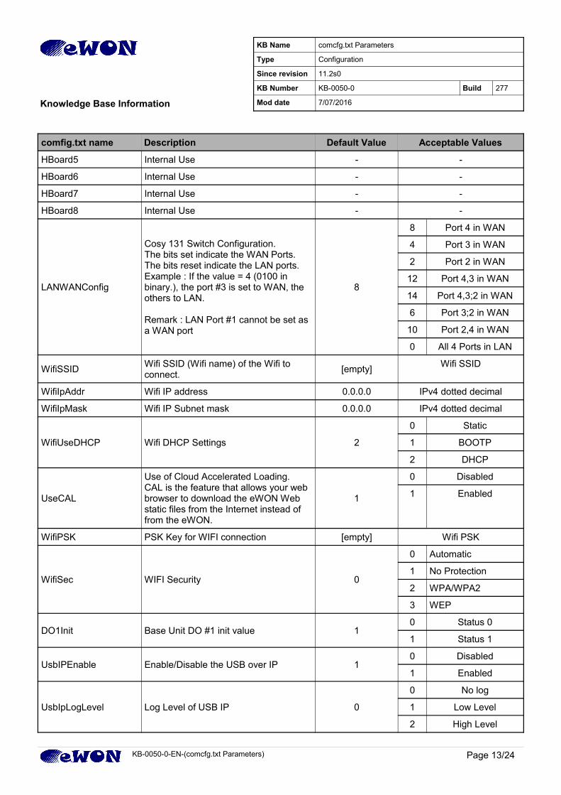
comfig.txt name Description Default Value Acceptable Values
HBoard5 Internal Use - -
HBoard6 Internal Use - -
HBoard7 Internal Use - -
HBoard8 Internal Use - -
LANWANConfig
Cosy 131 Switch Configuration.The bits set indicate the WAN Ports. The bits reset indicate the LAN ports.Example : If the value = 4 (0100 in binary.), the port #3 is set to WAN, the others to LAN.
Remark : LAN Port #1 cannot be set as a WAN port
8
8 Port 4 in WAN
4 Port 3 in WAN
2 Port 2 in WAN
12 Port 4,3 in WAN
14 Port 4,3;2 in WAN
6 Port 3;2 in WAN
10 Port 2,4 in WAN
0 All 4 Ports in LAN
WifiSSIDWifi SSID (Wifi name) of the Wifi to connect.
[empty]Wifi SSID
WifiIpAddr Wifi IP address 0.0.0.0 IPv4 dotted decimal
WifiIpMask Wifi IP Subnet mask 0.0.0.0 IPv4 dotted decimal
WifiUseDHCP Wifi DHCP Settings 2
0 Static
1 BOOTP
2 DHCP
UseCAL
Use of Cloud Accelerated Loading. CAL is the feature that allows your web browser to download the eWON Web static files from the Internet instead of from the eWON.
1
0 Disabled
1 Enabled
WifiPSK PSK Key for WIFI connection [empty] Wifi PSK
WifiSec WIFI Security 0
0 Automatic
1 No Protection
2 WPA/WPA2
3 WEP
DO1Init Base Unit DO #1 init value 10 Status 0
1 Status 1
UsbIPEnable Enable/Disable the USB over IP 10 Disabled
1 Enabled
UsbIpLogLevel Log Level of USB IP 0
0 No log
1 Low Level
2 High Level
KB-0050-0-EN-(comcfg.txt Parameters) Page 13/24
KB Name comcfg.txt Parameters
Type Configuration
Since revision 11.2s0
KB Number KB-0050-0 Build 277
Knowledge Base Information Mod date 7/07/2016
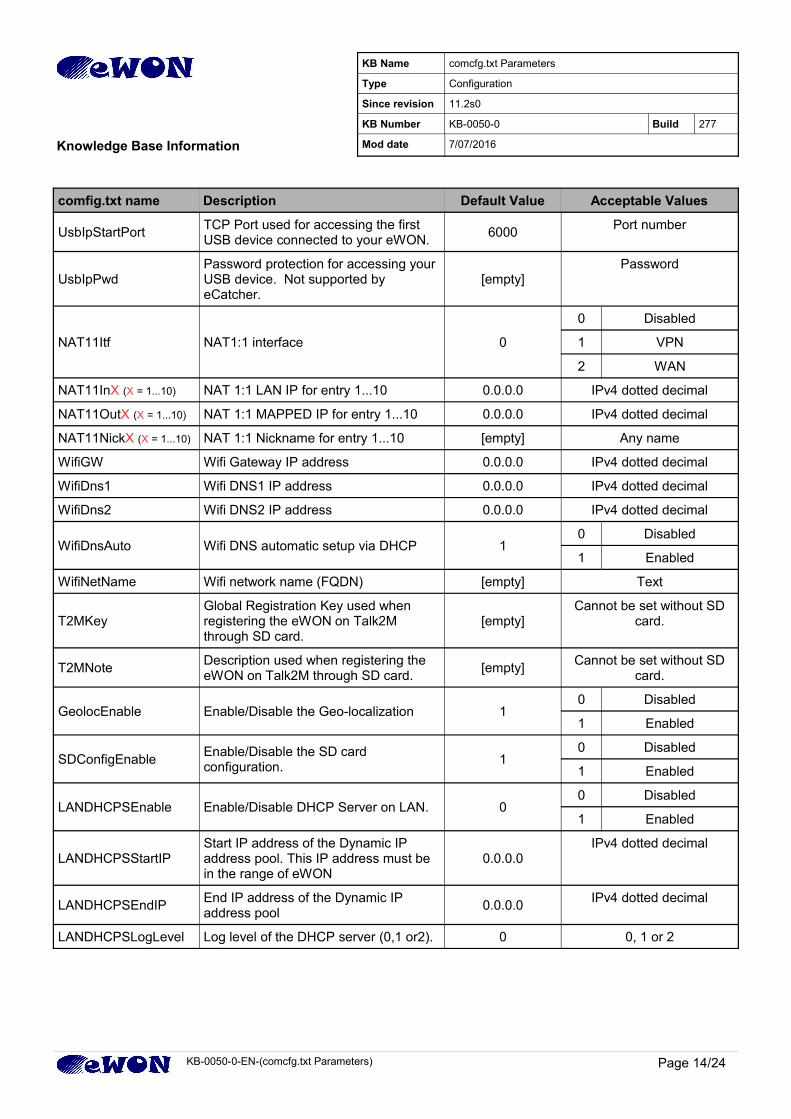
comfig.txt name Description Default Value Acceptable Values
UsbIpStartPortTCP Port used for accessing the first USB device connected to your eWON.
6000Port number
UsbIpPwdPassword protection for accessing your USB device. Not supported by eCatcher.
[empty]Password
NAT11Itf NAT1:1 interface 0
0 Disabled
1 VPN
2 WAN
NAT11InX (X = 1...10) NAT 1:1 LAN IP for entry 1...10 0.0.0.0 IPv4 dotted decimal
NAT11OutX (X = 1...10) NAT 1:1 MAPPED IP for entry 1...10 0.0.0.0 IPv4 dotted decimal
NAT11NickX (X = 1...10) NAT 1:1 Nickname for entry 1...10 [empty] Any name
WifiGW Wifi Gateway IP address 0.0.0.0 IPv4 dotted decimal
WifiDns1 Wifi DNS1 IP address 0.0.0.0 IPv4 dotted decimal
WifiDns2 Wifi DNS2 IP address 0.0.0.0 IPv4 dotted decimal
WifiDnsAuto Wifi DNS automatic setup via DHCP 10 Disabled
1 Enabled
WifiNetName Wifi network name (FQDN) [empty] Text
T2MKeyGlobal Registration Key used when registering the eWON on Talk2M through SD card.
[empty]Cannot be set without SD
card.
T2MNoteDescription used when registering the eWON on Talk2M through SD card.
[empty]Cannot be set without SD
card.
GeolocEnable Enable/Disable the Geo-localization 10 Disabled
1 Enabled
SDConfigEnableEnable/Disable the SD card configuration.
10 Disabled
1 Enabled
LANDHCPSEnable Enable/Disable DHCP Server on LAN. 00 Disabled
1 Enabled
LANDHCPSStartIPStart IP address of the Dynamic IP address pool. This IP address must be in the range of eWON
0.0.0.0IPv4 dotted decimal
LANDHCPSEndIPEnd IP address of the Dynamic IP address pool
0.0.0.0IPv4 dotted decimal
LANDHCPSLogLevel Log level of the DHCP server (0,1 or2). 0 0, 1 or 2
KB-0050-0-EN-(comcfg.txt Parameters) Page 14/24
KB Name comcfg.txt Parameters
Type Configuration
Since revision 11.2s0
KB Number KB-0050-0 Build 277
Knowledge Base Information Mod date 7/07/2016
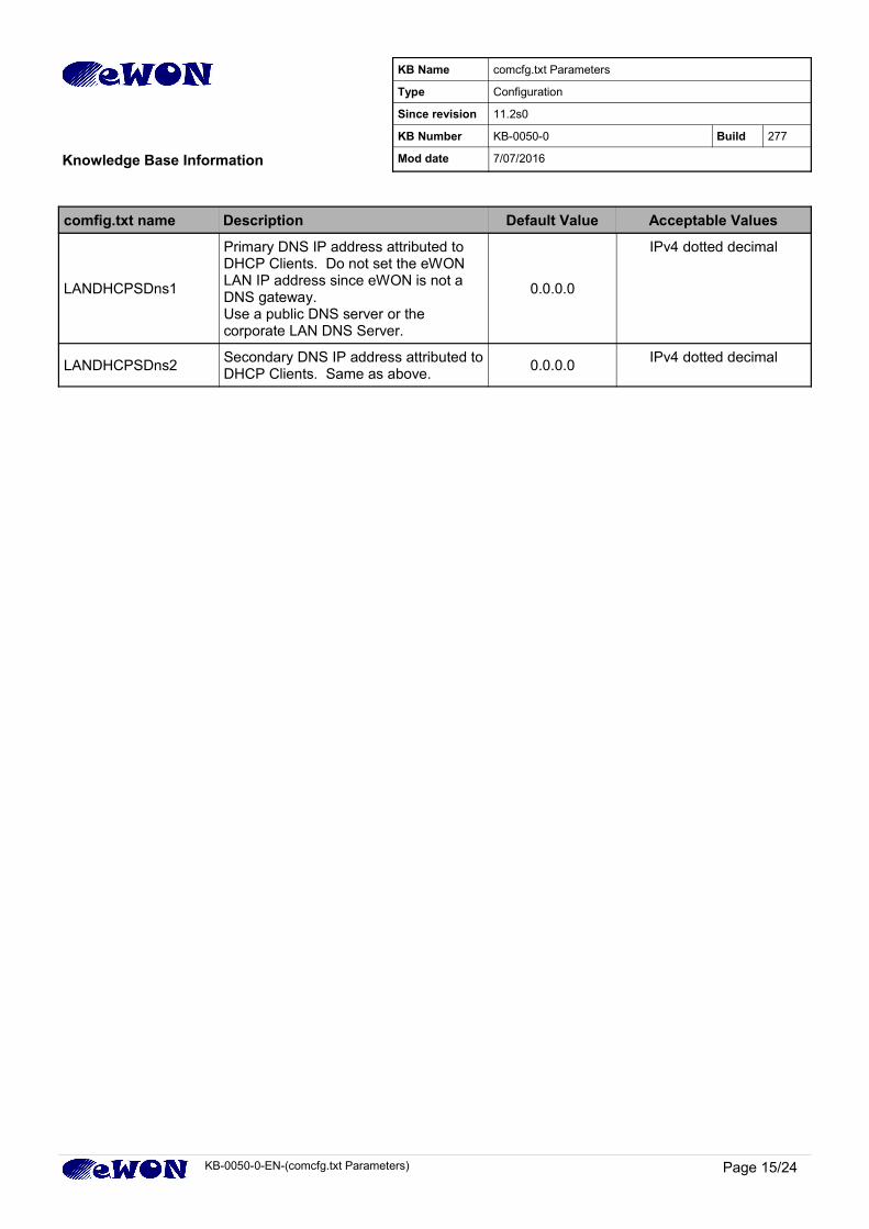
comfig.txt name Description Default Value Acceptable Values
LANDHCPSDns1
Primary DNS IP address attributed to DHCP Clients. Do not set the eWON LAN IP address since eWON is not a DNS gateway.Use a public DNS server or the corporate LAN DNS Server.
0.0.0.0
IPv4 dotted decimal
LANDHCPSDns2Secondary DNS IP address attributed toDHCP Clients. Same as above.
0.0.0.0IPv4 dotted decimal
KB-0050-0-EN-(comcfg.txt Parameters) Page 15/24
KB Name comcfg.txt Parameters
Type Configuration
Since revision 11.2s0
KB Number KB-0050-0 Build 277
Knowledge Base Information Mod date 7/07/2016
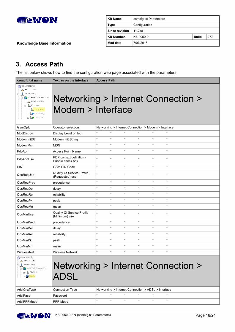
3. Access Path The list below shows how to find the configuration web page associated with the parameters.
comcfg.txt name Text as on the interface Access Path
Networking > Internet Connection > Modem > Interface
GsmOpId Operator selection Networking > Internet Connection > Modem > Interface
ModDispLvl Display Level on led “ “ “ “ “ “
ModemInitStr Modem Init String “ “ “ “ “ “
ModemMsn MSN “ “ “ “ “ “
PdpApn Access Point Name “ “ “ “ “ “
PdpApnUsePDP context definition - Enable check box
“ “ “ “ “ “
PIN GSM PIN Code “ “ “ “ “ “
QosReqUseQuality Of Service Profile (Requested) use
“ “ “ “ “ “
QosReqPred precedence “ “ “ “ “ “
QosReqDel delay “ “ “ “ “ “
QosReqRel reliability “ “ “ “ “ “
QosReqPk peak “ “ “ “ “ “
QosReqMn mean “ “ “ “ “ “
QosMinUseQuality Of Service Profile (Minimum) use
“ “ “ “ “ “
QosMinPred precedence “ “ “ “ “ “
QosMinDel delay “ “ “ “ “ “
QosMinRel reliability “ “ “ “ “ “
QosMinPk peak “ “ “ “ “ “
QosMinMn mean “ “ “ “ “ “
WirelessNet Wireless Network “ “ “ “ “ “
Networking > Internet Connection > ADSL
AdslCnxType Connection Type Networking > Internet Connection > ADSL > Interface
AdslPass Password “ “ “ “ “ “
AdslPPPMode PPP Mode “ “ “ “ “ “
KB-0050-0-EN-(comcfg.txt Parameters) Page 16/24
KB Name comcfg.txt Parameters
Type Configuration
Since revision 11.2s0
KB Number KB-0050-0 Build 277
Knowledge Base Information Mod date 7/07/2016
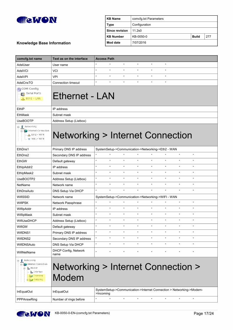
comcfg.txt name Text as on the interface Access Path
AdslUser User name “ “ “ “ “ “
AdslVCI VCI “ “ “ “ “ “
AdslVPI VPI “ “ “ “ “ “
AdslCnxTO Connection timeout “ “ “ “ “ “
Ethernet - LANEthIP IP address
EthMask Subnet mask
UseBOOTP Address Setup (Listbox)
Networking > Internet ConnectionEthDns1 Primary DNS IP address SystemSetup->Communication->Networking->Eth2 - WAN
EthDns2 Secondary DNS IP address “ “ “ “ “ “ “ “
EthGW Default gateway “ “ “ “ “ “ “ “
EthIpAddr2 IP address “ “ “ “ “ “ “ “
EthIpMask2 Subnet mask “ “ “ “ “ “ “ “
UseBOOTP2 Address Setup (Listbox) “ “ “ “ “ “ “ “
NetName Network name “ “ “ “ “ “ “ “
EthDnsAuto DNS Setup Via DHCP “ “ “ “ “ “ “ “
WifiSSID Network name SystemSetup->Communication->Networking->WIFI - WAN
WifiPSK Network Passphrase “ “ “ “ “ “ “ “
WifiIpAddr IP address “ “ “ “ “ “ “ “
WifiIpMask Subnet mask “ “ “ “ “ “ “ “
WifiUseDHCP Address Setup (Listbox) “ “ “ “ “ “ “ “
WifiGW Default gateway “ “ “ “ “ “ “ “
WifiDNS1 Primary DNS IP address “ “ “ “ “ “ “ “
WifiDNS2 Secondary DNS IP address “ “ “ “ “ “ “ “
WifiDNSAuto DNS Setup Via DHCP “ “ “ “ “ “ “ “
WifiNetNameDHCP Config, Network name
“ “ “ “ “ “ “ “
Networking > Internet Connection > Modem
InEqualOut InEqualOutSystemSetup->Communication->Internet Connection > Networking->Modem->Incoming
PPPAnswRing Number of rings before “ “ “ “ “ “ “ “
KB-0050-0-EN-(comcfg.txt Parameters) Page 17/24
KB Name comcfg.txt Parameters
Type Configuration
Since revision 11.2s0
KB Number KB-0050-0 Build 277
Knowledge Base Information Mod date 7/07/2016
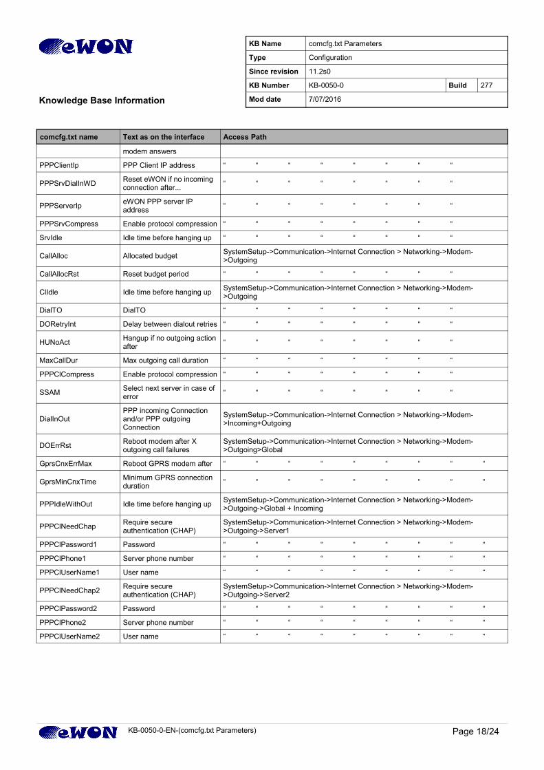
comcfg.txt name Text as on the interface Access Path
modem answers
PPPClientIp PPP Client IP address “ “ “ “ “ “ “ “
PPPSrvDialInWDReset eWON if no incoming connection after...
“ “ “ “ “ “ “ “
PPPServerIpeWON PPP server IP address
“ “ “ “ “ “ “ “
PPPSrvCompress Enable protocol compression “ “ “ “ “ “ “ “
SrvIdle Idle time before hanging up “ “ “ “ “ “ “ “
CallAlloc Allocated budget SystemSetup->Communication->Internet Connection > Networking->Modem->Outgoing
CallAllocRst Reset budget period “ “ “ “ “ “ “ “
ClIdle Idle time before hanging up SystemSetup->Communication->Internet Connection > Networking->Modem->Outgoing
DialTO DialTO “ “ “ “ “ “ “ “
DORetryInt Delay between dialout retries “ “ “ “ “ “ “ “
HUNoActHangup if no outgoing actionafter
“ “ “ “ “ “ “ “
MaxCallDur Max outgoing call duration “ “ “ “ “ “ “ “
PPPClCompress Enable protocol compression “ “ “ “ “ “ “ “
SSAMSelect next server in case of error
“ “ “ “ “ “ “ “
DialInOutPPP incoming Connection and/or PPP outgoing Connection
SystemSetup->Communication->Internet Connection > Networking->Modem->Incoming+Outgoing
DOErrRstReboot modem after X outgoing call failures
SystemSetup->Communication->Internet Connection > Networking->Modem->Outgoing>Global
GprsCnxErrMax Reboot GPRS modem after “ “ “ “ “ “ “ “ “
GprsMinCnxTimeMinimum GPRS connection duration
“ “ “ “ “ “ “ “ “
PPPIdleWithOut Idle time before hanging up SystemSetup->Communication->Internet Connection > Networking->Modem->Outgoing->Global + Incoming
PPPClNeedChapRequire secure authentication (CHAP)
SystemSetup->Communication->Internet Connection > Networking->Modem->Outgoing->Server1
PPPClPassword1 Password “ “ “ “ “ “ “ “ “
PPPClPhone1 Server phone number “ “ “ “ “ “ “ “ “
PPPClUserName1 User name “ “ “ “ “ “ “ “ “
PPPClNeedChap2Require secure authentication (CHAP)
SystemSetup->Communication->Internet Connection > Networking->Modem->Outgoing->Server2
PPPClPassword2 Password “ “ “ “ “ “ “ “ “
PPPClPhone2 Server phone number “ “ “ “ “ “ “ “ “
PPPClUserName2 User name “ “ “ “ “ “ “ “ “
KB-0050-0-EN-(comcfg.txt Parameters) Page 18/24
KB Name comcfg.txt Parameters
Type Configuration
Since revision 11.2s0
KB Number KB-0050-0 Build 277
Knowledge Base Information Mod date 7/07/2016
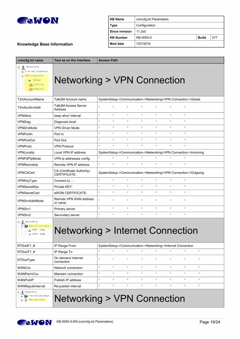
comcfg.txt name Text as on the interface Access Path
Networking > VPN Connection
T2mAccountName Talk2M Account name SystemSetup->Communication->Networking>VPN Connection->Global
T2mAccSrvAddrTalk2M Access Server Address
“ “ “ “ “ “ “
VPNAlive keep alive' interval “ “ “ “ “ “ “
VPNDiag Diagnosis level “ “ “ “ “ “ “
VPNDrvMode VPN Driver Mode “ “ “ “ “ “ “
VPNPortIn Port In “ “ “ “ “ “ “
VPNPortOut Port Out “ “ “ “ “ “ “
VPNProto VPN Protocol “ “ “ “ “ “ “
VPNLocalIp Local VPN IP address SystemSetup->Communication->Networking>VPN Connection->Incoming
VPNP2PIpMode VPN Ip addresses config “ “ “ “ “ “ “
VPNRemoteIp Remote VPN IP address “ “ “ “ “ “ “
VPNCACertCA (Certificate Authority) CERTIFICATE:
SystemSetup->Communication->Networking>VPN Connection->Outgoing
VPNKeyType Connect to…: “ “ “ “ “ “ “
VPNSecretKey Private KEY: “ “ “ “ “ “ “
VPNSecretCert eWON CERTIFICATE: “ “ “ “ “ “ “
VPNSrvAddrModeRemote VPN WAN address or name
“ “ “ “ “ “ “
VPNSrv1 Primary server “ “ “ “ “ “ “
VPNSrv2 Secondary server “ “ “ “ “ “ “
Networking > Internet ConnectionRTDodF1..# IP Range From SystemSetup->Communication->Networking->Internet Connection
RTDodT1..# IP Range To “ “ “ “ “ “ “ “
RTDodTypeOn demand Internet connection
“ “ “ “ “ “ “ “
WANCnx Network connection “ “ “ “ “ “ “ “
WANPermCnx Maintain connection “ “ “ “ “ “ “ “
WANPubIP Publish IP address “ “ “ “ “ “ “ “
WANRepubInterval Re-publish interval “ “ “ “ “ “ “ “
Networking > VPN Connection
KB-0050-0-EN-(comcfg.txt Parameters) Page 19/24
KB Name comcfg.txt Parameters
Type Configuration
Since revision 11.2s0
KB Number KB-0050-0 Build 277
Knowledge Base Information Mod date 7/07/2016
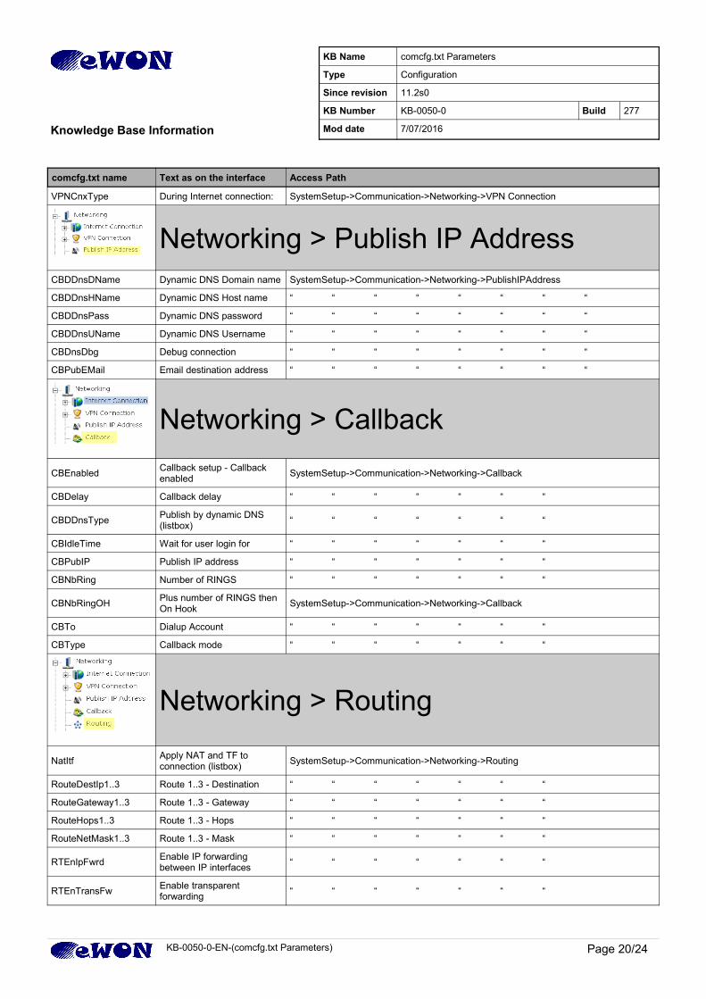
comcfg.txt name Text as on the interface Access Path
VPNCnxType During Internet connection: SystemSetup->Communication->Networking->VPN Connection
Networking > Publish IP AddressCBDDnsDName Dynamic DNS Domain name SystemSetup->Communication->Networking->PublishIPAddress
CBDDnsHName Dynamic DNS Host name “ “ “ “ “ “ “ “
CBDDnsPass Dynamic DNS password “ “ “ “ “ “ “ “
CBDDnsUName Dynamic DNS Username “ “ “ “ “ “ “ “
CBDnsDbg Debug connection “ “ “ “ “ “ “ “
CBPubEMail Email destination address “ “ “ “ “ “ “ “
Networking > Callback
CBEnabledCallback setup - Callback enabled
SystemSetup->Communication->Networking->Callback
CBDelay Callback delay “ “ “ “ “ “ “
CBDDnsTypePublish by dynamic DNS (listbox)
“ “ “ “ “ “ “
CBIdleTime Wait for user login for “ “ “ “ “ “ “
CBPubIP Publish IP address “ “ “ “ “ “ “
CBNbRing Number of RINGS “ “ “ “ “ “ “
CBNbRingOHPlus number of RINGS then On Hook
SystemSetup->Communication->Networking->Callback
CBTo Dialup Account “ “ “ “ “ “ “
CBType Callback mode “ “ “ “ “ “ “
Networking > Routing
NatItfApply NAT and TF to connection (listbox)
SystemSetup->Communication->Networking->Routing
RouteDestIp1..3 Route 1..3 - Destination “ “ “ “ “ “ “
RouteGateway1..3 Route 1..3 - Gateway “ “ “ “ “ “ “
RouteHops1..3 Route 1..3 - Hops “ “ “ “ “ “ “
RouteNetMask1..3 Route 1..3 - Mask “ “ “ “ “ “ “
RTEnIpFwrdEnable IP forwarding between IP interfaces
“ “ “ “ “ “ “
RTEnTransFwEnable transparent forwarding
“ “ “ “ “ “ “
KB-0050-0-EN-(comcfg.txt Parameters) Page 20/24
KB Name comcfg.txt Parameters
Type Configuration
Since revision 11.2s0
KB Number KB-0050-0 Build 277
Knowledge Base Information Mod date 7/07/2016
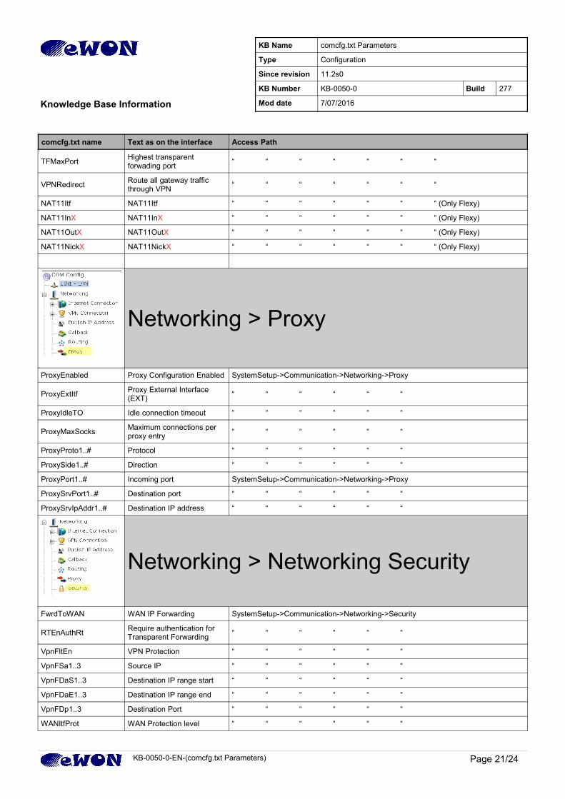
comcfg.txt name Text as on the interface Access Path
TFMaxPortHighest transparent forwading port
“ “ “ “ “ “ “
VPNRedirectRoute all gateway traffic through VPN
“ “ “ “ “ “ “
NAT11Itf NAT11Itf “ “ “ “ “ “ “ (Only Flexy)
NAT11InX NAT11InX “ “ “ “ “ “ “ (Only Flexy)
NAT11OutX NAT11OutX “ “ “ “ “ “ “ (Only Flexy)
NAT11NickX NAT11NickX “ “ “ “ “ “ “ (Only Flexy)
Networking > Proxy
ProxyEnabled Proxy Configuration Enabled SystemSetup->Communication->Networking->Proxy
ProxyExtItfProxy External Interface (EXT)
“ “ “ “ “ “
ProxyIdleTO Idle connection timeout “ “ “ “ “ “
ProxyMaxSocksMaximum connections per proxy entry
“ “ “ “ “ “
ProxyProto1..# Protocol “ “ “ “ “ “
ProxySide1..# Direction “ “ “ “ “ “
ProxyPort1..# Incoming port SystemSetup->Communication->Networking->Proxy
ProxySrvPort1..# Destination port “ “ “ “ “ “
ProxySrvIpAddr1..# Destination IP address “ “ “ “ “ “
Networking > Networking Security
FwrdToWAN WAN IP Forwarding SystemSetup->Communication->Networking->Security
RTEnAuthRtRequire authentication for Transparent Forwarding
“ “ “ “ “ “
VpnFltEn VPN Protection “ “ “ “ “ “
VpnFSa1..3 Source IP “ “ “ “ “ “
VpnFDaS1..3 Destination IP range start “ “ “ “ “ “
VpnFDaE1..3 Destination IP range end “ “ “ “ “ “
VpnFDp1..3 Destination Port “ “ “ “ “ “
WANItfProt WAN Protection level “ “ “ “ “ “
KB-0050-0-EN-(comcfg.txt Parameters) Page 21/24
KB Name comcfg.txt Parameters
Type Configuration
Since revision 11.2s0
KB Number KB-0050-0 Build 277
Knowledge Base Information Mod date 7/07/2016
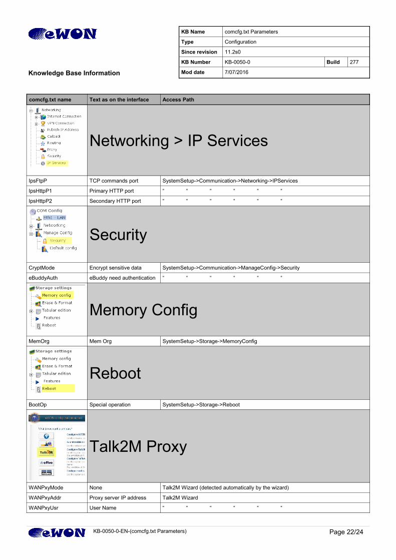
comcfg.txt name Text as on the interface Access Path
Networking > IP Services
IpsFtpP TCP commands port SystemSetup->Communication->Networking->IPServices
IpsHttpP1 Primary HTTP port “ “ “ “ “ “
IpsHttpP2 Secondary HTTP port “ “ “ “ “ “
Security
CryptMode Encrypt sensitive data SystemSetup->Communication->ManageConfig->Security
eBuddyAuth eBuddy need authentication “ “ “ “ “ “
Memory Config
MemOrg Mem Org SystemSetup->Storage->MemoryConfig
Reboot
BootOp Special operation SystemSetup->Storage->Reboot
Talk2M Proxy
WANPxyMode None Talk2M Wizard (detected automatically by the wizard)
WANPxyAddr Proxy server IP address Talk2M Wizard
WANPxyUsr User Name “ “ “ “ “ “
KB-0050-0-EN-(comcfg.txt Parameters) Page 22/24
KB Name comcfg.txt Parameters
Type Configuration
Since revision 11.2s0
KB Number KB-0050-0 Build 277
Knowledge Base Information Mod date 7/07/2016
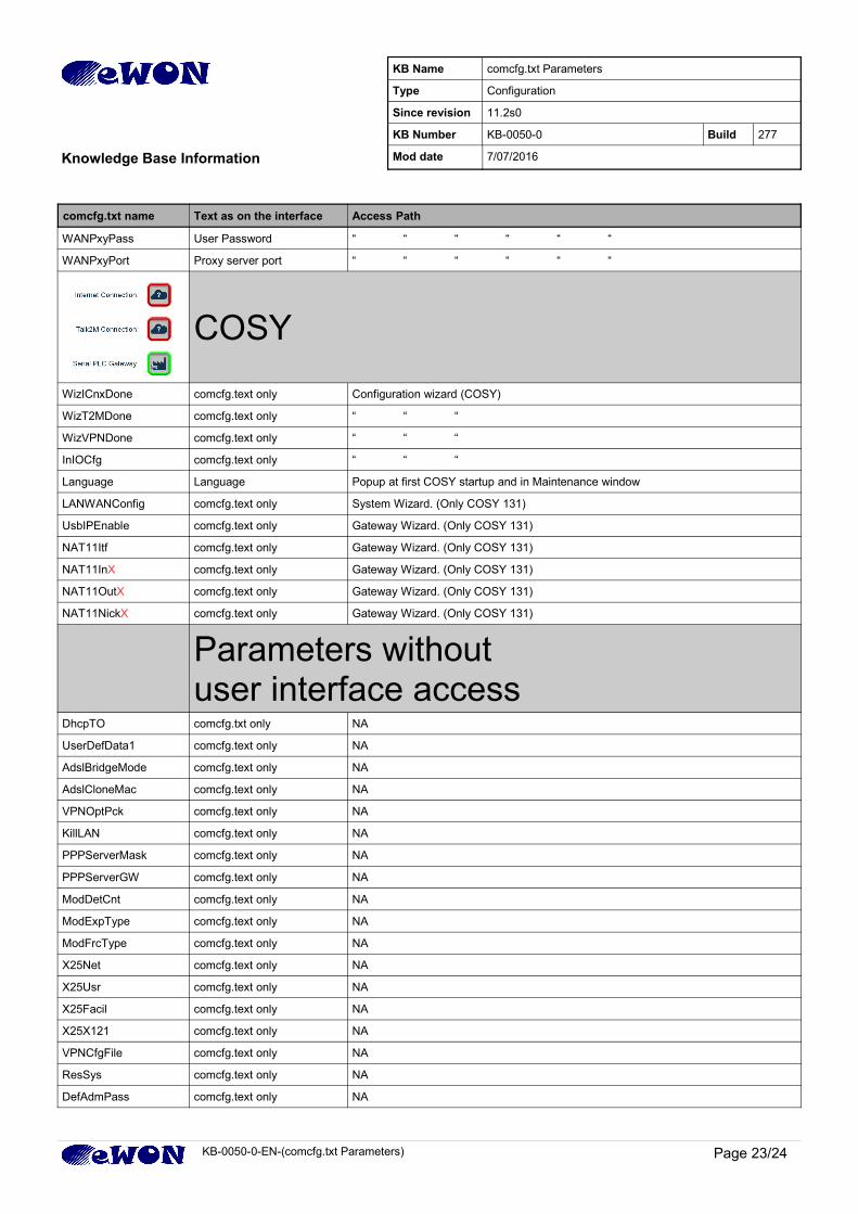
comcfg.txt name Text as on the interface Access Path
WANPxyPass User Password “ “ “ “ “ “
WANPxyPort Proxy server port “ “ “ “ “ “
COSY
WizICnxDone comcfg.text only Configuration wizard (COSY)
WizT2MDone comcfg.text only “ “ “
WizVPNDone comcfg.text only “ “ “
InIOCfg comcfg.text only “ “ “
Language Language Popup at first COSY startup and in Maintenance window
LANWANConfig comcfg.text only System Wizard. (Only COSY 131)
UsbIPEnable comcfg.text only Gateway Wizard. (Only COSY 131)
NAT11Itf comcfg.text only Gateway Wizard. (Only COSY 131)
NAT11InX comcfg.text only Gateway Wizard. (Only COSY 131)
NAT11OutX comcfg.text only Gateway Wizard. (Only COSY 131)
NAT11NickX comcfg.text only Gateway Wizard. (Only COSY 131)
Parameters without user interface access
DhcpTO comcfg.txt only NA
UserDefData1 comcfg.text only NA
AdslBridgeMode comcfg.text only NA
AdslCloneMac comcfg.text only NA
VPNOptPck comcfg.text only NA
KillLAN comcfg.text only NA
PPPServerMask comcfg.text only NA
PPPServerGW comcfg.text only NA
ModDetCnt comcfg.text only NA
ModExpType comcfg.text only NA
ModFrcType comcfg.text only NA
X25Net comcfg.text only NA
X25Usr comcfg.text only NA
X25Facil comcfg.text only NA
X25X121 comcfg.text only NA
VPNCfgFile comcfg.text only NA
ResSys comcfg.text only NA
DefAdmPass comcfg.text only NA
KB-0050-0-EN-(comcfg.txt Parameters) Page 23/24
KB Name comcfg.txt Parameters
Type Configuration
Since revision 11.2s0
KB Number KB-0050-0 Build 277
Knowledge Base Information Mod date 7/07/2016
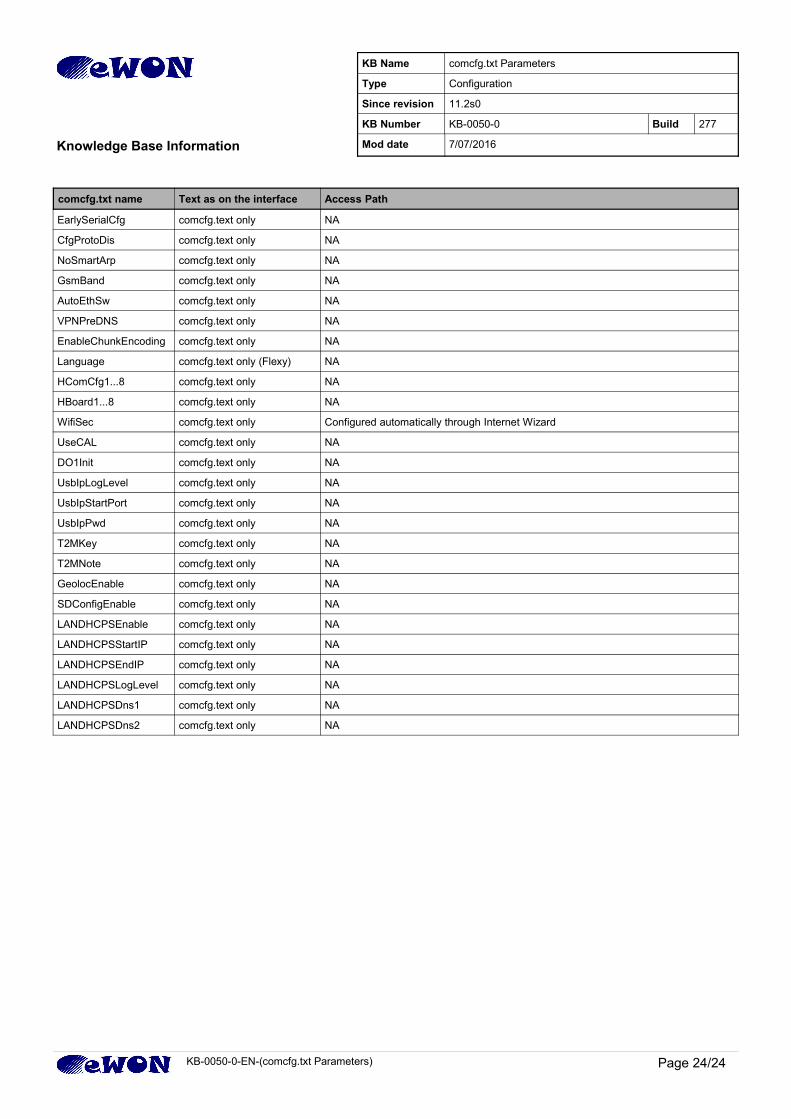
comcfg.txt name Text as on the interface Access Path
EarlySerialCfg comcfg.text only NA
CfgProtoDis comcfg.text only NA
NoSmartArp comcfg.text only NA
GsmBand comcfg.text only NA
AutoEthSw comcfg.text only NA
VPNPreDNS comcfg.text only NA
EnableChunkEncoding comcfg.text only NA
Language comcfg.text only (Flexy) NA
HComCfg1...8 comcfg.text only NA
HBoard1...8 comcfg.text only NA
WifiSec comcfg.text only Configured automatically through Internet Wizard
UseCAL comcfg.text only NA
DO1Init comcfg.text only NA
UsbIpLogLevel comcfg.text only NA
UsbIpStartPort comcfg.text only NA
UsbIpPwd comcfg.text only NA
T2MKey comcfg.text only NA
T2MNote comcfg.text only NA
GeolocEnable comcfg.text only NA
SDConfigEnable comcfg.text only NA
LANDHCPSEnable comcfg.text only NA
LANDHCPSStartIP comcfg.text only NA
LANDHCPSEndIP comcfg.text only NA
LANDHCPSLogLevel comcfg.text only NA
LANDHCPSDns1 comcfg.text only NA
LANDHCPSDns2 comcfg.text only NA
KB-0050-0-EN-(comcfg.txt Parameters) Page 24/24
KB Name comcfg.txt Parameters
Type Configuration
Since revision 11.2s0
KB Number KB-0050-0 Build 277
Knowledge Base Information Mod date 7/07/2016