Embed Size (px)
Citation preview
SELECTOR SWITCH DRIVE MECHANISM TERMINAL BOARD
66KV TAP CHANGER
TYPE ABS 66
Type ABS66 is a 3 phase, single compartment,
externally mounted on load tap changer. This OLTC
works on the principle of high speed transition
resistance and is suitable for both star and delta
connected transformers with linear tap
arrangement.
There are two different models, 17 positions 300 A
and 23 positions 300A (refer technical data for
details). The OLTC 17 position rated for 300A
follows an asymmetrical pennant cycle whereas
the 23 positions 300A OLTC follows a bi-directional
flag cycle. The tap changers have a maximum
current and voltage rating of 300A and 72kV
respectively.
These OLTCs may be used on transformers up to
60MVA. They are available for a maximum of 23
positions, so they can be applied to a winding of 22
steps to give 23 different voltages. The compact
design, easy maintenance and low oil requirement
adds advantages to this tap changer.
The entire tap changer unit with a selector switch and a
drive mechanism chamber are housed in a sheet metal
enclosure. The switch chamber and the drive mechanism
are separated by a metal sheet. The fixed contacts are
mounted on phase boards. The moving contact slides
over these fixed contacts and selects the tap. This is
done in all the three phases simultaneously by a selector
switch. The selector switch combines the functions of a
tap selector and a diverter switch. The drive mechanism
is coupled to this selector switch by a drive shaft and
series of gears. It also has an energy storage device that
releases the energy to drive the selector switch.
MOUNTING ON TRANSFORMER :
The tap changer is mounted on the transformer by
taking out leads via the epoxy cast terminal board of the
tap-changer, which is supplied with the OLTC.
PROTECTIVE DEVICE :
The tap-changer is protected by an oil surge protective
relay (OSR) which is connected to a conservator. Though
OSR is supplied with the tap changer, the conservator
and transformer oil are not part of our supply. A pressure
relief device can be provided in addition as per customer
requirements.
TECHNICAL DETAILS
CONSTRUCTION DETAILS
www.onloadgears.com
A
C
E
D
B
C
L TERMINAL BOARD
L PORT &
C
13
L PORTC
L TERMINAL BOARDC 12
47
61
2
9
60
31
6
30
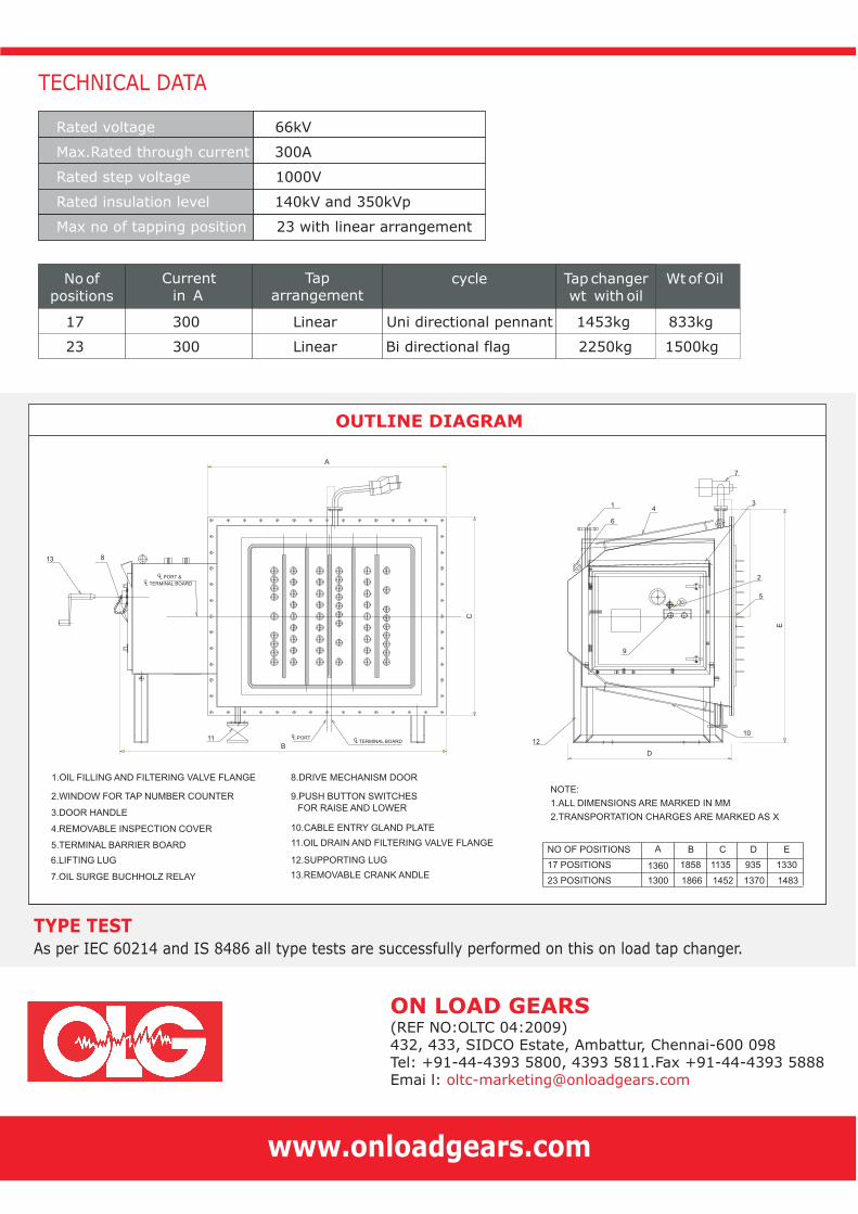
1.OIL FILLING AND FILTERING VALVE FLANGE
2.WINDOW FOR TAP NUMBER COUNTER
3.DOOR HANDLE
4.REMOVABLE INSPECTION COVER
5.TERMINAL BARRIER BOARD
6.LIFTING LUG
7.OIL SURGE BUCHHOLZ RELAY
12.SUPPORTING LUG
11.OIL DRAIN AND FILTERING VALVE FLANGE
8.DRIVE MECHANISM DOOR
9.PUSH BUTTON SWITCHES
13.REMOVABLE CRANK ANDLE
10.CABLE ENTRY GLAND PLATE
ANO OF POSITIONS B C D E
17 POSITIONS 1858 1135 935 1330 1360
23 POSITIONS 1300 1866 1452 1370 1483
NOTE:
1.ALL DIMENSIONS ARE MARKED IN MM
2.TRANSPORTATION CHARGES ARE MARKED AS X
FOR RAISE AND LOWER
4
7
8
1110
2
5
TECHNICAL DATA
Rated voltage 66kV
Max.Rated through current 300A
Rated step voltage 1000V
Rated insulation level 140kV and 350kVp
Max no of tapping position 23 with linear arrangement
Tap changer
wt with oilNoof
positions
Current
in A
Tap
arrangementcycle WtofOil
17 300 Linear Uni directional pennant 1453kg 833kg
23 300 Linear Bi directional flag 2250kg 1500kg
ON LOAD GEARS
(REF NO:OLTC 04:2009)
432, 433, SIDCO Estate, Ambattur, Chennai-600 098
Tel: +91-44-4393 5800, 4393 5811.Fax +91-44-4393 5888
Emai l:
OUTLINE DIAGRAM
TYPE TESTAs per IEC 60214 and IS 8486 all type tests are successfully performed on this on load tap changer.

![11KV TAP CHANGER TYPE [A] ABS - On Load Gears LOAD GEARS 11KV TAP CHANGER TYPE [A] ABS TECHNICAL DETAILS [A]ABS11 OLTC is air insulated, externally mounted On Load Tap Changer. This](https://img.pdfslide.net/doc/110x75/5aaeb09e7f8b9adb688ca6f2/11kv-tap-changer-type-a-abs-on-load-load-gears-11kv-tap-changer-type-a-abs.jpg)