Embed Size (px)
Citation preview
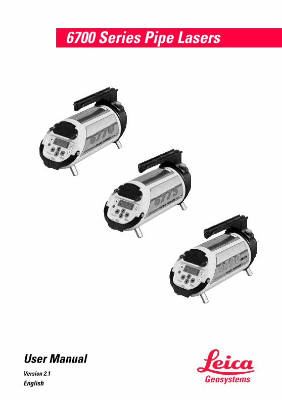
6700 Series Pipe Lasers
User ManualVersion 2.1
English

This manual contains important Safety Directions (refer to chapter Safety Directions) as well as instructions for setting up the product and operating it.
Read carefully through the User Manual before you switch on the instrument.
The symbols used in the User Manual have the following meaning:
�DANGER:Indicates an imminently hazardous situation which, if not avoided, will
result in death or serious injury.
�WARNING:Indicates a potentially hazardous situation or an unintended use which, if
not avoided, could result in death or serious injury.
�CAUTION:Indicates a potentially hazardous situation or an unintended use which, if
not avoided, may result in minor or moderate injury and / or appreciable material, financial and environmental damage.
! Important paragraphs which must be adhered to in practice as they enable the product to be used in a technically correct and efficient manner.
Product IdentificationThe instrument model and serial number of your product are indicated on the label on the base of the unit.
Enter the model and serial number in your manual and always refer to this information when you need to contact your agency or authorized service workshop.
Model-Serial Number: ________________ Date of purchase:_____________
Copyright NoticeCopyright 2003 by Leica Geosystems GR LLC. All rights reserved
Leica Geosystems Proprietary Information
The information/data contained herein is proprietary information of Leica Geosystems GR LLC and is furnished for your controlled use, and shall not be copied or otherwise reproduced, nor in any manner disclosed to any third party, without Leica Geosystems�s prior written consent.
26700 Series Pipe Lasers-2.1.0en

Table of Contents
Introduction.................................. 4Features......................................... 4
Function Description ................. 5General Procedures ................... 7
Entering Small Grade Changes..... 7Entering Large Grade Changes..... 8Locking/Unlocking Grade............... 8Locking/Unlocking Line.................. 9Alignmaster Mode and the Wireless Remote ........................... 9Using Alignmaster Mode.............. 10Centering the Line ....................... 10Beam Control............................... 10Setting up a Target Assembly...... 11Setting up a Trivet Plate Assembly ..................................... 11Typical Next Day Set-up .............. 12
Standard Set-up Procedures . 13Pre-Poured Invert ........................ 13Open Trench (Transit) ................. 13In Pipe/On Top of Pipe ................ 14Open Trench (Stringline) ............. 14Manhole ....................................... 15Drop Manhole .............................. 16Using the Over-the-Top Mount Assembly ..................................... 16
Refraction ................................... 17Accessories ............................... 19
Target Assembly and Inserts ....... 19Wireless Remote ......................... 19Trivet Plate Assembly .................. 20Drop-Manhold Assembly ............. 20Transit Tower and Accessories ... 20Support Feet ................................ 20Other Accessories ....................... 21Recharging the Battery Pack ....... 21
Calibration Procedure ............. 24Checking Line and Grade ....... 26Troubleshooting........................ 27Technical Data........................... 31Warranty...................................... 32Care and Transport .................. 33
Transport ..................................... 33Storage ........................................ 33Cleaning and Drying Windows .... 33
Safety Directions ...................... 34Intended Use of Product .............. 34
Permitted uses........................... 34Adverse uses............................. 34
Limits of Use................................ 34Responsibilities............................ 35Hazards of Use............................ 35Laser classification, 6770/6775 (red) ........................... 37
Labeling (6770/6775 red) .......... 39Laser classification, 6790 (green) ................................ 39
Labeling (6790 green) ............... 41Electromagnetic Compatibility (EMC) .......................................... 41FCC Statement (applicable in the U.S.) ................ 42
Product Labeling........................ 42Remote Control ......................... 42Laser System............................. 43
3 6700 Series Pipe Lasers-2.1.0enTable of Contents
Introduction
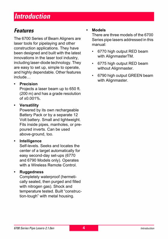
FeaturesThe 6700 Series of Beam Aligners are laser tools for pipelaying and other construction applications. They have been designed and built with the latest innovations in the laser tool industry, including laser-diode technology. They are easy to set up, simple to operate, and highly dependable. Other features include�
� PrecisionProjects a laser beam up to 650 ft. (200 m) and has a grade resolution of ±0.001%.
� VersatilityPowered by its own rechargeable Battery Pack or by a separate 12 Volt battery. Small and lightweight. Fits inside pipes, manholes, or pre-poured inverts. Can be used above-ground, too.
� IntelligenceSelf-levels. Seeks and locates the center of a target automatically for easy second-day set-ups (6770 and 6790 Models only). Operates with a Wireless Remote Control.
� RuggednessCompletely waterproof (hermeti-cally sealed, then purged and filled with nitrogen gas). Shock and temperature tested. Built �construc-tion-tough� with metal housing.
� ModelsThere are three models of the 6700 Series pipe lasers addressed in this manual:
� 6770 high output RED beam with AlignmasterTM.
� 6775 high output RED beam without Alignmaster.
� 6790 high output GREEN beam with Alignmaster.
4 Introduction6700 Series Pipe Lasers-2.1.0en
Function Description
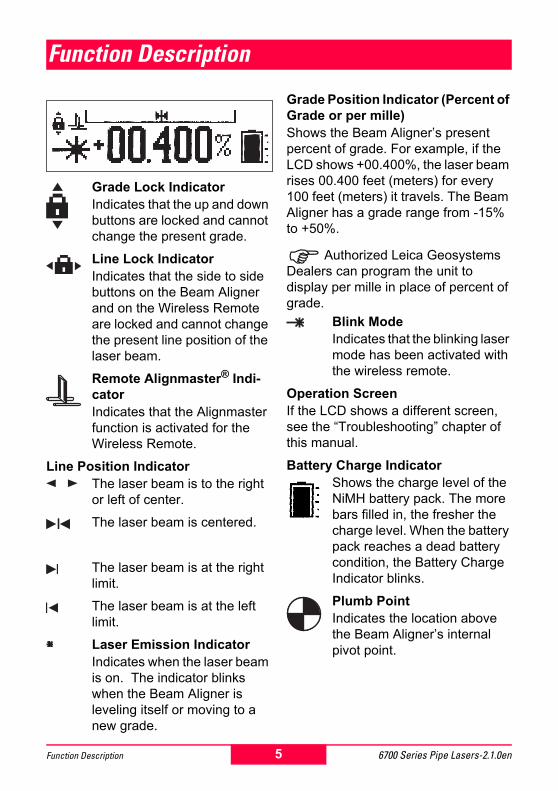
Grade Lock IndicatorIndicates that the up and down buttons are locked and cannot change the present grade.
Line Lock IndicatorIndicates that the side to side buttons on the Beam Aligner and on the Wireless Remote are locked and cannot change the present line position of the laser beam.
Remote Alignmaster® Indi-catorIndicates that the Alignmaster function is activated for the Wireless Remote.
Line Position IndicatorThe laser beam is to the right or left of center.
The laser beam is centered.
The laser beam is at the right limit.
The laser beam is at the left limit.
Laser Emission IndicatorIndicates when the laser beam is on. The indicator blinks when the Beam Aligner is leveling itself or moving to a new grade.
Grade Position Indicator (Percent of Grade or per mille)Shows the Beam Aligner�s present percent of grade. For example, if the LCD shows +00.400%, the laser beam rises 00.400 feet (meters) for every 100 feet (meters) it travels. The Beam Aligner has a grade range from -15% to +50%.
!Authorized Leica Geosystems Dealers can program the unit to display per mille in place of percent of grade.
Blink ModeIndicates that the blinking laser mode has been activated with the wireless remote.
Operation ScreenIf the LCD shows a different screen, see the �Troubleshooting� chapter of this manual.
Battery Charge IndicatorShows the charge level of the NiMH battery pack. The more bars filled in, the fresher the charge level. When the battery pack reaches a dead battery condition, the Battery Charge Indicator blinks.
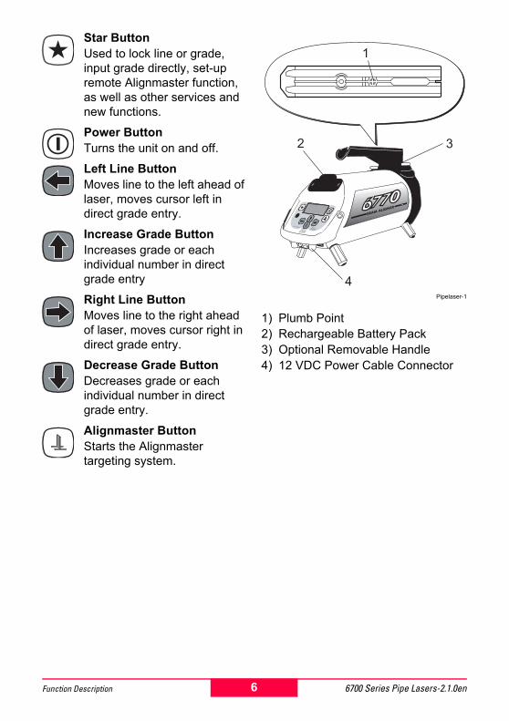
Plumb PointIndicates the location above the Beam Aligner�s internal pivot point.
5 6700 Series Pipe Lasers-2.1.0enFunction Description
Star ButtonUsed to lock line or grade, input grade directly, set-up remote Alignmaster function, as well as other services and new functions.
Power ButtonTurns the unit on and off.
Left Line ButtonMoves line to the left ahead of laser, moves cursor left in direct grade entry.
Increase Grade ButtonIncreases grade or each individual number in direct grade entry
Right Line ButtonMoves line to the right ahead of laser, moves cursor right in direct grade entry.
Decrease Grade ButtonDecreases grade or each individual number in direct grade entry.
Alignmaster ButtonStarts the Alignmaster targeting system.
Pipelaser-1
1) Plumb Point2) Rechargeable Battery Pack3) Optional Removable Handle4) 12 VDC Power Cable Connector
1
32
4
6 6700 Series Pipe Lasers-2.1.0enFunction Description

General Procedures
!Refer to the procedures below when setting up and operating the Beam Aligner. (To set up for a specific application, see the �Standard Set-up Procedures� chapter of this manual.) You must always define the following three variables in any application:Grade - the amount of rise or fall over the distance of the pipe to be laid. Set the grade by entering the percent of grade into the Beam Aligner.
Pipelaser-2
Elevation - the distance from the invert of the pipe to the laser beam. Set by attaching the Support Feet for the pipe size (8�, 200mm, standard all other sizes optional) to be laid or by adjusting the height of the Beam Aligner on the Trivet Plate Assembly.
Pipelaser-3
Line - the position of the laser beam relative to the centerline of the pipe to be laid. Set the line by aligning the laser beam with the next manhole.
Pipelaser-4
Entering Small Grade Changes
1. Press and hold the Power Button briefly to start the Beam Aligner.
2. Observe the LCD and do the following:� Press and hold the Up
Button to increase grade.
� Press and hold the Down Button to decrease grade.
! The longer you press and hold the button, the faster the numbers change on the LCD.3. When the LCD shows the required
percent of grade, release the button. The Laser Emission Indi-cator blinks as the Beam Aligner self-levels to the selected grade.
7 6700 Series Pipe Lasers-2.1.0enGeneral Procedures
Entering Large Grade Changes
1. Press and hold the Power Button briefly to start the Beam Aligner.
2. Press the Star Button.
3. Observe the LCD and do the following:� Press Left or Right to
move through the character positions.
� Press Up or Down to set the value of the selected character.
4. When the LCD shows the required percent of grade, press the Star Button. The Laser Emission Indicator blinks as the Beam Aligner self-levels to the selected grade.
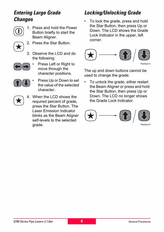
Locking/Unlocking Grade� To lock the grade, press and hold
the Star Button, then press Up or Down. The LCD shows the Grade Lock Indicator in the upper, left corner.
Pipelaser-5
The up and down buttons cannot be used to change the grade.
� To unlock the grade, either restart the Beam Aligner or press and hold the Star Button, then press Up or Down. The LCD no longer shows the Grade Lock Indicator.
Pipelaser-6
8 General Procedures6700 Series Pipe Lasers-2.1.0en
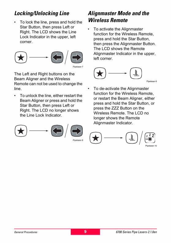
Locking/Unlocking Line� To lock the line, press and hold the
Star Button, then press Left or Right. The LCD shows the Line Lock Indicator in the upper, left corner.
Pipelaser-7
The Left and Right buttons on the Beam Aligner and the Wireless Remote can not be used to change the line.
� To unlock the line, either restart the Beam Aligner or press and hold the Star Button, then press Left or Right. The LCD no longer shows the Line Lock Indicator.
Pipelaser-8
Alignmaster Mode and the Wireless Remote� To activate the Alignmaster
function for the Wireless Remote, press and hold the Star Button, then press the Alignmaster Button. The LCD shows the Remote Alignmaster Indicator in the upper, left corner.
Pipelaser-9
� To de-activate the Alignmaster function for the Wireless Remote, or restart the Beam Aligner, either press and hold the Star Button, or press the ZZZ Button on the Wireless Remote. The LCD no longer shows the Remote Alignmaster Indicator.
Pipelaser-10
9 6700 Series Pipe Lasers-2.1.0enGeneral Procedures
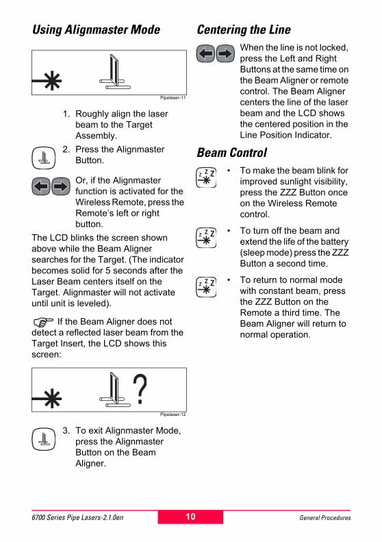
Using Alignmaster Mode
Pipelaser-11
1. Roughly align the laser beam to the Target Assembly.
2. Press the Alignmaster Button.
Or, if the Alignmaster function is activated for the Wireless Remote, press the Remote�s left or right button.
The LCD blinks the screen shown above while the Beam Aligner searches for the Target. (The indicator becomes solid for 5 seconds after the Laser Beam centers itself on the Target. Alignmaster will not activate until unit is leveled).
! If the Beam Aligner does not detect a reflected laser beam from the Target Insert, the LCD shows this screen:
Pipelaser-12
3. To exit Alignmaster Mode, press the Alignmaster Button on the Beam Aligner.
Centering the LineWhen the line is not locked, press the Left and Right Buttons at the same time on the Beam Aligner or remote control. The Beam Aligner centers the line of the laser beam and the LCD shows the centered position in the Line Position Indicator.
Beam Control� To make the beam blink for
improved sunlight visibility, press the ZZZ Button once on the Wireless Remote control.
� To turn off the beam and extend the life of the battery (sleep mode) press the ZZZ Button a second time.
� To return to normal mode with constant beam, press the ZZZ Button on the Remote a third time. The Beam Aligner will return to normal operation.
10 General Procedures6700 Series Pipe Lasers-2.1.0en
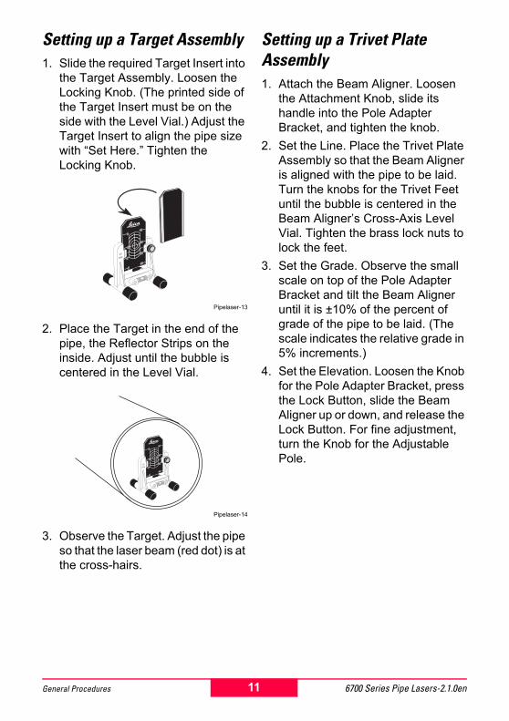
Setting up a Target Assembly1. Slide the required Target Insert into
the Target Assembly. Loosen the Locking Knob. (The printed side of the Target Insert must be on the side with the Level Vial.) Adjust the Target Insert to align the pipe size with �Set Here.� Tighten the Locking Knob.
Pipelaser-13
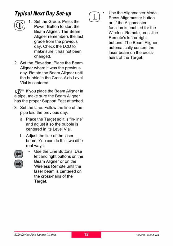
2. Place the Target in the end of the pipe, the Reflector Strips on the inside. Adjust until the bubble is centered in the Level Vial.
Pipelaser-14
3. Observe the Target. Adjust the pipe so that the laser beam (red dot) is at the cross-hairs.
Setting up a Trivet Plate Assembly1. Attach the Beam Aligner. Loosen
the Attachment Knob, slide its handle into the Pole Adapter Bracket, and tighten the knob.
2. Set the Line. Place the Trivet Plate Assembly so that the Beam Aligner is aligned with the pipe to be laid. Turn the knobs for the Trivet Feet until the bubble is centered in the Beam Aligner�s Cross-Axis Level Vial. Tighten the brass lock nuts to lock the feet.
3. Set the Grade. Observe the small scale on top of the Pole Adapter Bracket and tilt the Beam Aligner until it is ±10% of the percent of grade of the pipe to be laid. (The scale indicates the relative grade in 5% increments.)
4. Set the Elevation. Loosen the Knob for the Pole Adapter Bracket, press the Lock Button, slide the Beam Aligner up or down, and release the Lock Button. For fine adjustment, turn the Knob for the Adjustable Pole.
11 6700 Series Pipe Lasers-2.1.0enGeneral Procedures
Typical Next Day Set-up1. Set the Grade. Press the
Power Button to start the Beam Aligner. The Beam Aligner remembers the last grade from the previous day. Check the LCD to make sure it has not been changed.
2. Set the Elevation. Place the Beam Aligner where it was the previous day. Rotate the Beam Aligner until the bubble in the Cross-Axis Level Vial is centered.
! If you place the Beam Aligner in a pipe, make sure the Beam Aligner has the proper Support Feet attached.3. Set the Line. Follow the line of the
pipe laid the previous day.a. Place the Target so it is �in-line�
and adjust it so the bubble is centered in its Level Vial.
b. Adjust the line of the laser beam. You can do this two diffe-rent ways:
� Use the Line Buttons. Use left and right buttons on the Beam Aligner or on the Wireless Remote until the laser beam is centered on the cross-hairs of the Target.
� Use the Alignmaster Mode. Press Alignmaster button or, if the Alignmaster function is enabled for the Wireless Remote, press the Remote�s left or right buttons. The Beam Aligner automatically centers the laser beam on the cross-hairs of the Target.
12 General Procedures6700 Series Pipe Lasers-2.1.0en
Standard Set-up Procedures
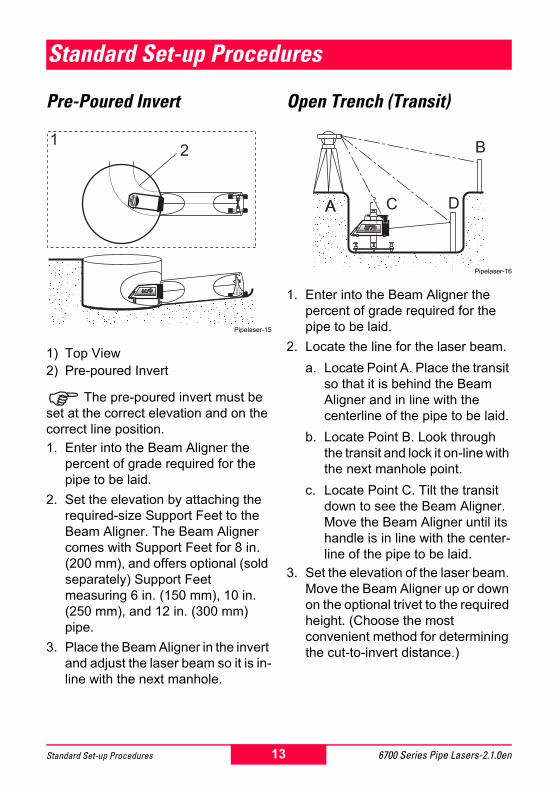
Pre-Poured Invert
Pipelaser-15
1) Top View2) Pre-poured Invert
! The pre-poured invert must be set at the correct elevation and on the correct line position.1. Enter into the Beam Aligner the
percent of grade required for the pipe to be laid.
2. Set the elevation by attaching the required-size Support Feet to the Beam Aligner. The Beam Aligner comes with Support Feet for 8 in. (200 mm), and offers optional (sold separately) Support Feet measuring 6 in. (150 mm), 10 in. (250 mm), and 12 in. (300 mm) pipe.
3. Place the Beam Aligner in the invert and adjust the laser beam so it is in-line with the next manhole.
Open Trench (Transit)
Pipelaser-16
1. Enter into the Beam Aligner the percent of grade required for the pipe to be laid.
2. Locate the line for the laser beam.a. Locate Point A. Place the transit
so that it is behind the Beam Aligner and in line with the centerline of the pipe to be laid.
b. Locate Point B. Look through the transit and lock it on-line with the next manhole point.
c. Locate Point C. Tilt the transit down to see the Beam Aligner. Move the Beam Aligner until its handle is in line with the center-line of the pipe to be laid.
3. Set the elevation of the laser beam. Move the Beam Aligner up or down on the optional trivet to the required height. (Choose the most convenient method for determining the cut-to-invert distance.)
21
AA
B
C D
13 6700 Series Pipe Lasers-2.1.0enStandard Set-up Procedures
4. Align the line of the laser beam by locating Point D. Tilt the transit up and use it to align a new stake approximately 15 ft. (5 m) in front of the Beam Aligner. Look through the transit and use the left and right buttons on the Wireless Remote until the laser beam hits the stake and intersects the transit�s cross-hairs.
In Pipe/On Top of Pipe
Pipelaser-17
!Place the Beam Aligner on top of a pipe when the laser beam can not pass through the pipe, such as when it is filled with water.1. Enter into the Beam Aligner the
percent of grade required for the pipe to be laid.
2. If you are going to place the Beam Aligner in the pipe, set the elevation by attaching the required-size Support Feet to the Beam Aligner. The Beam Aligner comes with Support Feet for 8 in. (200 mm), and offers optional (sold separately) Support Feet measuring 6 in. (150 mm), 10 in. (250 mm), and 12 in. (300 mm) pipe.
3. Place the Beam Aligner in or on the pipe and adjust the laser beam so it is in-line with the next manhole.
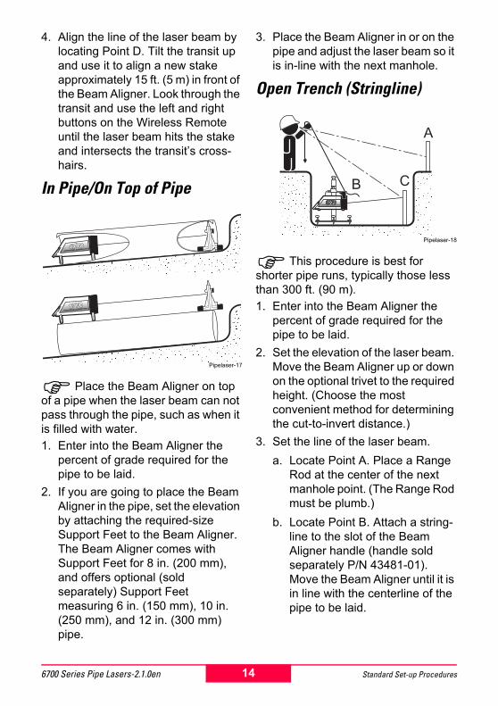
Open Trench (Stringline)
Pipelaser-18
! This procedure is best for shorter pipe runs, typically those less than 300 ft. (90 m).1. Enter into the Beam Aligner the
percent of grade required for the pipe to be laid.
2. Set the elevation of the laser beam. Move the Beam Aligner up or down on the optional trivet to the required height. (Choose the most convenient method for determining the cut-to-invert distance.)
3. Set the line of the laser beam.a. Locate Point A. Place a Range
Rod at the center of the next manhole point. (The Range Rod must be plumb.)
b. Locate Point B. Attach a string-line to the slot of the Beam Aligner handle (handle sold separately P/N 43481-01). Move the Beam Aligner until it is in line with the centerline of the pipe to be laid.
A
B C
14 Standard Set-up Procedures6700 Series Pipe Lasers-2.1.0en
c. Locate Point C. Stand behind the Beam Aligner, close one eye, and hold the stringline up. Align the stringline with the Range Rod. Glance down and align a new stake approximately 15 ft. (5 m) in front of the Beam Aligner. Use the left and right buttons on the Wireless Remote until the laser beam hits the stake and intersects the string-line.
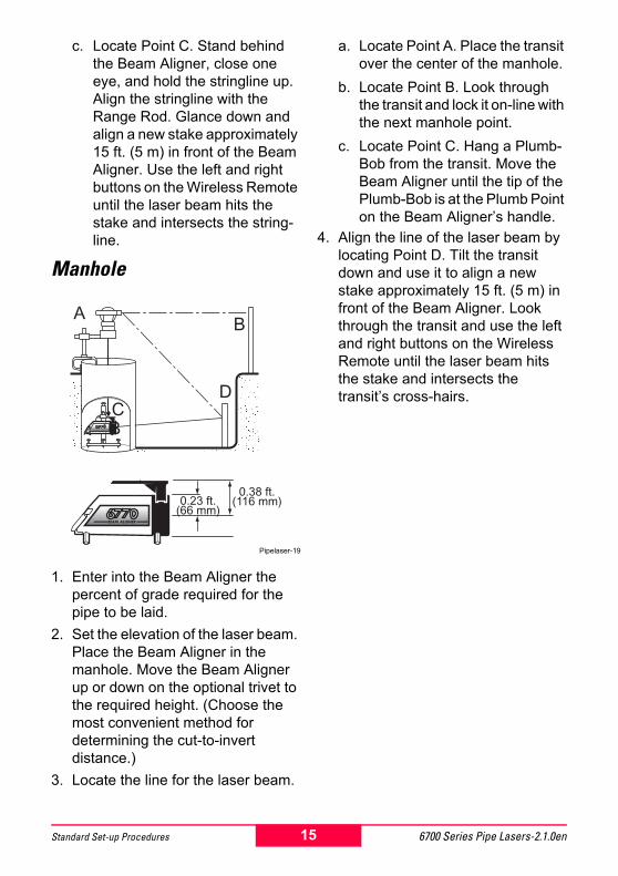
Manhole
Pipelaser-19
1. Enter into the Beam Aligner the percent of grade required for the pipe to be laid.
2. Set the elevation of the laser beam. Place the Beam Aligner in the manhole. Move the Beam Aligner up or down on the optional trivet to the required height. (Choose the most convenient method for determining the cut-to-invert distance.)
3. Locate the line for the laser beam.
a. Locate Point A. Place the transit over the center of the manhole.
b. Locate Point B. Look through the transit and lock it on-line with the next manhole point.
c. Locate Point C. Hang a Plumb-Bob from the transit. Move the Beam Aligner until the tip of the Plumb-Bob is at the Plumb Point on the Beam Aligner�s handle.
4. Align the line of the laser beam by locating Point D. Tilt the transit down and use it to align a new stake approximately 15 ft. (5 m) in front of the Beam Aligner. Look through the transit and use the left and right buttons on the Wireless Remote until the laser beam hits the stake and intersects the transit�s cross-hairs.
A
BC
B
D
0.23 ft.(66 mm)
0.38 ft.(116 mm)
15 6700 Series Pipe Lasers-2.1.0enStandard Set-up Procedures
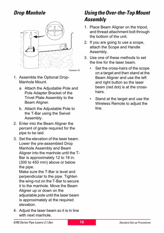
Drop Manhole
Pipelaser-20
1. Assemble the Optional Drop-Manhole Mount.a. Attach the Adjustable Pole and
Pole Adapter Bracket of the Trivet Plate Assembly to the Beam Aligner.
b. Attach the Adjustable Pole to the T-Bar using the Swivel Assembly.
2. Enter into the Beam Aligner the percent of grade required for the pipe to be laid.
3. Set the elevation of the laser beam. Lower the pre-assembled Drop Manhole Assembly and Beam Aligner into the manhole until the T-Bar is approximately 12 to 18 in. (300 to 450 mm) above or below the pipe.Make sure the T-Bar is level and perpendicular to the pipe. Tighten the wing-nut on the T-Bar to secure it to the manhole. Move the Beam Aligner up or down on the adjustable pole until the laser beam is approximately at the required elevation.
4. Adjust the laser beam so it is in line with next manhole.
Using the Over-the-Top Mount Assembly1. Place Beam Aligner on the tripod,
and thread attachment bolt through the bottom of the unit.
2. If you are going to use a scope, attach the Scope and Handle Assembly.
3. Use one of these methods to set the line for the laser beam.� Set the cross-hairs of the scope
on a target and then stand at the Beam Aligner and use the left and right button so the laser beam (red dot) is at the cross-hairs.
� Stand at the target and use the Wireless Remote to adjust the line.
16 Standard Set-up Procedures6700 Series Pipe Lasers-2.1.0en
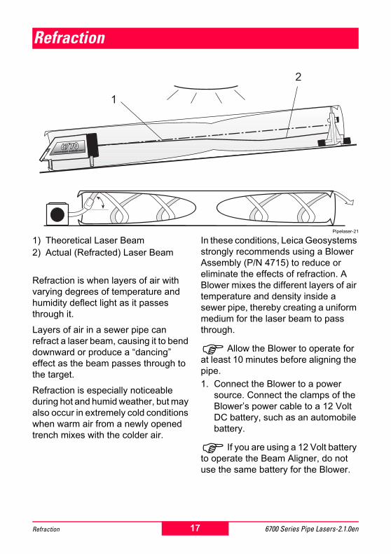
Refraction
Pipelaser-21
1) Theoretical Laser Beam2) Actual (Refracted) Laser Beam
Refraction is when layers of air with varying degrees of temperature and humidity deflect light as it passes through it.
Layers of air in a sewer pipe can refract a laser beam, causing it to bend downward or produce a �dancing� effect as the beam passes through to the target.
Refraction is especially noticeable during hot and humid weather, but may also occur in extremely cold conditions when warm air from a newly opened trench mixes with the colder air.
In these conditions, Leica Geosystems strongly recommends using a Blower Assembly (P/N 4715) to reduce or eliminate the effects of refraction. A Blower mixes the different layers of air temperature and density inside a sewer pipe, thereby creating a uniform medium for the laser beam to pass through.
!Allow the Blower to operate for at least 10 minutes before aligning the pipe.1. Connect the Blower to a power
source. Connect the clamps of the Blower�s power cable to a 12 Volt DC battery, such as an automobile battery.
! If you are using a 12 Volt battery to operate the Beam Aligner, do not use the same battery for the Blower.
1
2
17 6700 Series Pipe Lasers-2.1.0enRefraction
2. Position the Blower. Make sure the air intake for the Blower is not blocked. If possible, position the Blower so the temperature of the air it draws in is approximately the same as the air inside the pipe.
3. Determine whether to attach the Nozzle to the end of the Blower Hose.� If the pipe is 6 to 10 in. (150 to
250 mm) in diameter, use the nozzle.
� If the pipe diameter is greater than 10 in. (250 mm), you do not have to use the nozzle.
4. Use the clamps to attach the Blower Hose at the beginning of the pipe where the Laser is located. Position the end of the hose at a 60° angle to force the air to swirl as it travels through the pipe.
5. Apply power to the Blower and let it operate.
18 Refraction6700 Series Pipe Lasers-2.1.0en
Accessories
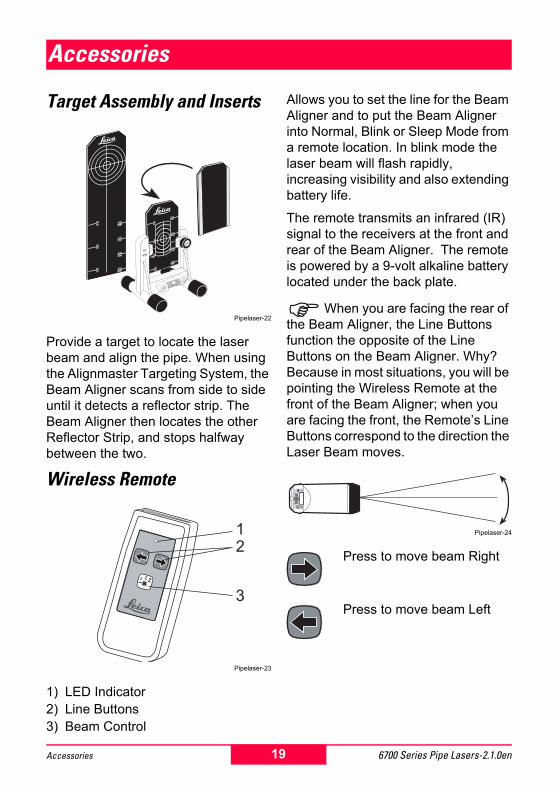
Target Assembly and Inserts
Pipelaser-22
Provide a target to locate the laser beam and align the pipe. When using the Alignmaster Targeting System, the Beam Aligner scans from side to side until it detects a reflector strip. The Beam Aligner then locates the other Reflector Strip, and stops halfway between the two.
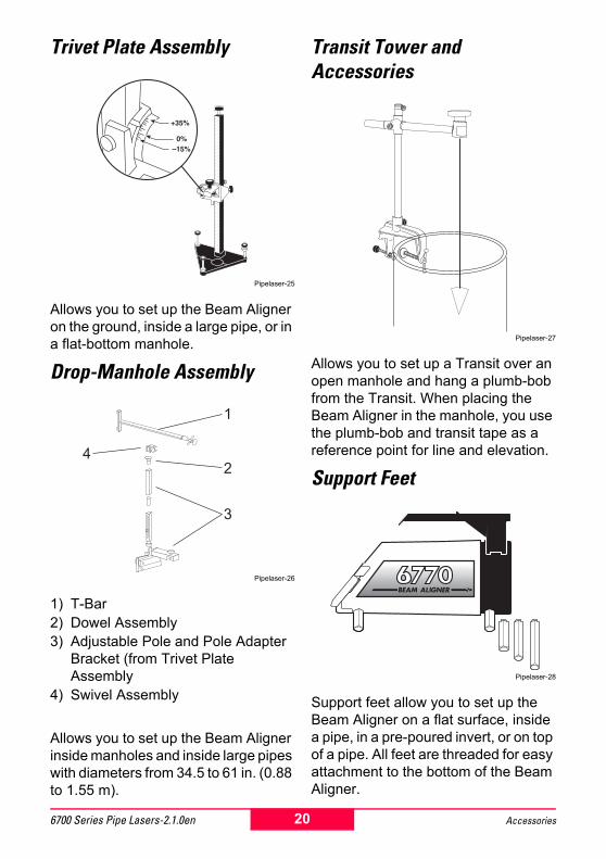
Wireless Remote
Pipelaser-23
1) LED Indicator2) Line Buttons3) Beam Control
Allows you to set the line for the Beam Aligner and to put the Beam Aligner into Normal, Blink or Sleep Mode from a remote location. In blink mode the laser beam will flash rapidly, increasing visibility and also extending battery life.
The remote transmits an infrared (IR) signal to the receivers at the front and rear of the Beam Aligner. The remote is powered by a 9-volt alkaline battery located under the back plate.
!When you are facing the rear of the Beam Aligner, the Line Buttons function the opposite of the Line Buttons on the Beam Aligner. Why? Because in most situations, you will be pointing the Wireless Remote at the front of the Beam Aligner; when you are facing the front, the Remote�s Line Buttons correspond to the direction the Laser Beam moves.
Pipelaser-24
Press to move beam Right
Press to move beam Left
12
3
19 6700 Series Pipe Lasers-2.1.0enAccessories
Trivet Plate Assembly
Pipelaser-25
Allows you to set up the Beam Aligner on the ground, inside a large pipe, or in a flat-bottom manhole.
Drop-Manhole Assembly
Pipelaser-26
1) T-Bar2) Dowel Assembly3) Adjustable Pole and Pole Adapter
Bracket (from Trivet Plate Assembly
4) Swivel Assembly
Allows you to set up the Beam Aligner inside manholes and inside large pipes with diameters from 34.5 to 61 in. (0.88 to 1.55 m).
Transit Tower and Accessories
Pipelaser-27
Allows you to set up a Transit over an open manhole and hang a plumb-bob from the Transit. When placing the Beam Aligner in the manhole, you use the plumb-bob and transit tape as a reference point for line and elevation.
Support Feet
Pipelaser-28
Support feet allow you to set up the Beam Aligner on a flat surface, inside a pipe, in a pre-poured invert, or on top of a pipe. All feet are threaded for easy attachment to the bottom of the Beam Aligner.
1
2
3
4
20 Accessories6700 Series Pipe Lasers-2.1.0en

Each Beam Aligner comes with 8� (200 mm) Support Feet. Available options include three sets of four feet. Each set allows the laser beam to be centered in standard-size pipes for quick second-day set-ups.
There is also an optional Third Foot that replaces the two back feet. Three feet (one in back, two in front) provide greater stability and balance when placing the Beam Aligner on uneven surfaces.
Other Accessories� Accessory Kit (red)
� Accessory Kit (green)
� Hex Key Tool Set
� 12 VDC Power Cable
� Scope and Handle Assembly
� Multiple Speed Blower Assembly
� Rechargeable Battery Pack (knobs)
� 110 VAC Charger
� 220 VAC Charger
� Automotive Charger
� Carrying Case
� Rubber Protection Boot
� Top Mount Handle Assembly
Recharging the Battery Pack
Pipelaser-29
!You can operate the Beam Aligner by connecting the Beam Aligner to a 12 Volt battery, such as a car or truck battery, with the 12 VDC Power Cable, SAP# 725875 (Red Boot�Positive Terminal; Black Boot�Negative Terminal). Do not run the vehicle�s engine when the cable is connected.1. Remove the Battery Pack.
a. Loosen screws on battery pack.b. Hold the Beam Aligner steady
with one hand and slide Battery Pack toward the rear with the other.
2. Charge the Battery Pack. Attach one of the following chargers to the connector on the Battery Pack:� 727477, 110 VAC
� 725857, 220 VAC
� 725944, 12 VDC, Cigarette Lighter Outlet
21 6700 Series Pipe Lasers-2.1.0enAccessories
Rechargeable NiMH Battery PackThe rechargeable Nickel Metal-Hydride battery pack assembly contains six high capacity NiMH batteries. The battery pack is an enclosed assembly. Fully charged, the battery pack will power the Beam Aligner up to 30 hours.
The battery pack must be removed from the laser to be charged using the Beam Aligner�s 110V/220V charger. The charger plugs into the charge jack on the back of the pack. The battery pack will reach full charge within 8 hours.
When re-installing the battery pack, ensure that the pack is fully pressed into the housing and that the knobs are screwed in before attempting to use the laser.
When the battery pack is installed and locked in position, it forms a watertight seal with the laser. Should your battery pack become wet, thoroughly dry the pack before reinstalling in the laser or putting into storage.
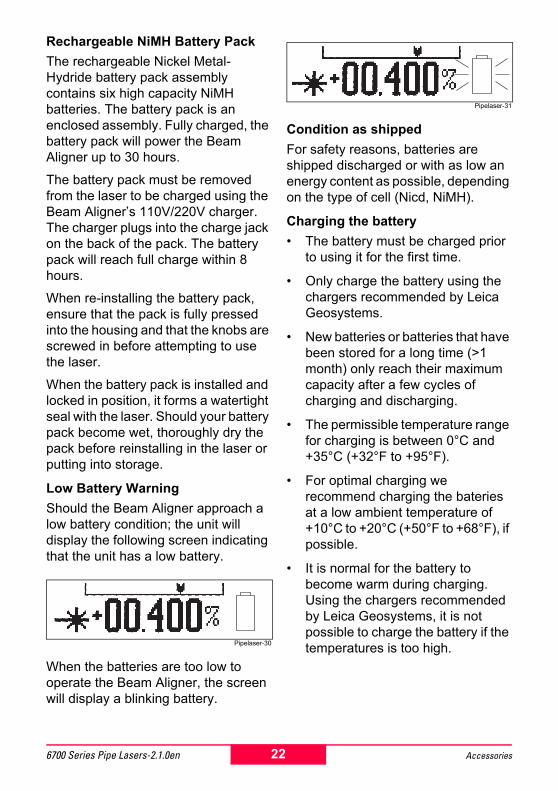
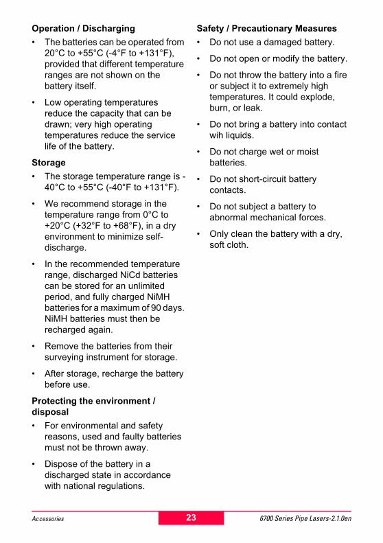
Low Battery WarningShould the Beam Aligner approach a low battery condition; the unit will display the following screen indicating that the unit has a low battery.
Pipelaser-30
When the batteries are too low to operate the Beam Aligner, the screen will display a blinking battery.
Pipelaser-31
Condition as shippedFor safety reasons, batteries are shipped discharged or with as low an energy content as possible, depending on the type of cell (Nicd, NiMH).
Charging the battery� The battery must be charged prior
to using it for the first time.
� Only charge the battery using the chargers recommended by Leica Geosystems.
� New batteries or batteries that have been stored for a long time (>1 month) only reach their maximum capacity after a few cycles of charging and discharging.
� The permissible temperature range for charging is between 0°C and +35°C (+32°F to +95°F).
� For optimal charging we recommend charging the bateries at a low ambient temperature of +10°C to +20°C (+50°F to +68°F), if possible.
� It is normal for the battery to become warm during charging. Using the chargers recommended by Leica Geosystems, it is not possible to charge the battery if the temperatures is too high.
22 Accessories6700 Series Pipe Lasers-2.1.0en
Operation / Discharging� The batteries can be operated from
20°C to +55°C (-4°F to +131°F), provided that different temperature ranges are not shown on the battery itself.
� Low operating temperatures reduce the capacity that can be drawn; very high operating temperatures reduce the service life of the battery.
Storage� The storage temperature range is -
40°C to +55°C (-40°F to +131°F).
� We recommend storage in the temperature range from 0°C to +20°C (+32°F to +68°F), in a dry environment to minimize self-discharge.
� In the recommended temperature range, discharged NiCd batteries can be stored for an unlimited period, and fully charged NiMH batteries for a maximum of 90 days. NiMH batteries must then be recharged again.
� Remove the batteries from their surveying instrument for storage.
� After storage, recharge the battery before use.
Protecting the environment / disposal� For environmental and safety
reasons, used and faulty batteries must not be thrown away.
� Dispose of the battery in a discharged state in accordance with national regulations.
Safety / Precautionary Measures� Do not use a damaged battery.
� Do not open or modify the battery.
� Do not throw the battery into a fire or subject it to extremely high temperatures. It could explode, burn, or leak.
� Do not bring a battery into contact wih liquids.
� Do not charge wet or moist batteries.
� Do not short-circuit battery contacts.
� Do not subject a battery to abnormal mechanical forces.
� Only clean the battery with a dry, soft cloth.
23 6700 Series Pipe Lasers-2.1.0enAccessories
Calibration Procedure
Pipelaser-32
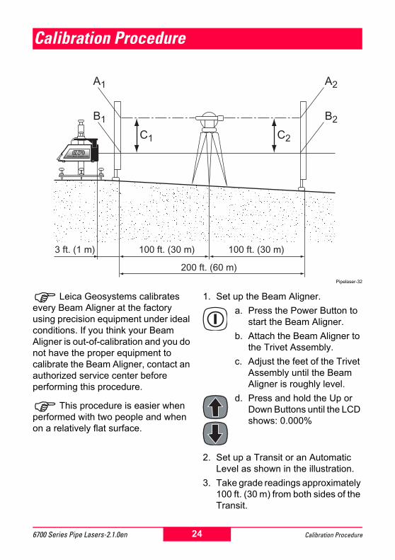
! Leica Geosystems calibrates every Beam Aligner at the factory using precision equipment under ideal conditions. If you think your Beam Aligner is out-of-calibration and you do not have the proper equipment to calibrate the Beam Aligner, contact an authorized service center before performing this procedure.
! This procedure is easier when performed with two people and when on a relatively flat surface.
1. Set up the Beam Aligner.a. Press the Power Button to
start the Beam Aligner.b. Attach the Beam Aligner to
the Trivet Assembly.c. Adjust the feet of the Trivet
Assembly until the Beam Aligner is roughly level.
d. Press and hold the Up or Down Buttons until the LCD shows: 0.000%
2. Set up a Transit or an Automatic Level as shown in the illustration.
3. Take grade readings approximately 100 ft. (30 m) from both sides of the Transit.
C1 C2
A1
B1
A2
B2
100 ft. (30 m)
200 ft. (60 m)
100 ft. (30 m)3 ft. (1 m)
24 Calibration Procedure6700 Series Pipe Lasers-2.1.0en
� Look through the Transit to the Grade Rod to take readings A1 and A2.
� Stand at the Grade Rod and note where the laser beam hits to take readings B1 and B2.
4. Subtract B1 from A1 to determine C1; subtract B2 from A2 to determine C2.� If C1 and C2 are the same for
both sides, the Beam Aligner is already calibrated correctly, and you are finished with this procedure.
� If C1 and C2 are not the same for both sides, you must calibrate the Beam Aligner. Go to the next step.
5. Use the up and down buttons to adjust the grade of the laser beam until C1 and C2 are equal.
!Be very careful not to move the Beam Aligner when pressing a Grade Button.
6. Reset the Beam Aligner�s level-grade position.a. Press the power button to turn
off the Beam Aligner b. Press and hold the up and right
button at the same time and then press the power button. (The LCD reverses its image.)
c. Press and hold the star button and then press the power button.(The LCD shows: 0.000%, and the Beam Aligner now considers its present grade position to be level.)
d. Press the power button again to exit the calibration mode.
7. Repeat Steps 3 and 4 to ensure the Beam Aligner is calibrated correctly.
25 6700 Series Pipe Lasers-2.1.0enCalibration Procedure
Checking Line and Grade
Pipelaser-33
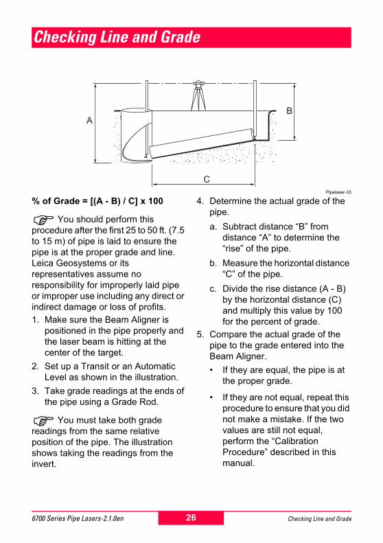
% of Grade = [(A - B) / C] x 100
!You should perform this procedure after the first 25 to 50 ft. (7.5 to 15 m) of pipe is laid to ensure the pipe is at the proper grade and line. Leica Geosystems or its representatives assume no responsibility for improperly laid pipe or improper use including any direct or indirect damage or loss of profits.1. Make sure the Beam Aligner is
positioned in the pipe properly and the laser beam is hitting at the center of the target.
2. Set up a Transit or an Automatic Level as shown in the illustration.
3. Take grade readings at the ends of the pipe using a Grade Rod.
!You must take both grade readings from the same relative position of the pipe. The illustration shows taking the readings from the invert.
4. Determine the actual grade of the pipe.a. Subtract distance �B� from
distance �A� to determine the �rise� of the pipe.
b. Measure the horizontal distance �C� of the pipe.
c. Divide the rise distance (A - B) by the horizontal distance (C) and multiply this value by 100 for the percent of grade.
5. Compare the actual grade of the pipe to the grade entered into the Beam Aligner.� If they are equal, the pipe is at
the proper grade.
� If they are not equal, repeat this procedure to ensure that you did not make a mistake. If the two values are still not equal, perform the �Calibration Procedure� described in this manual.
A
C
B
26 Checking Line and Grade6700 Series Pipe Lasers-2.1.0en
Troubleshooting
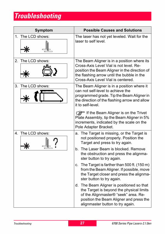
Symptom Possible Causes and Solutions1. The LCD shows: The laser has not yet leveled. Wait for the
laser to self level.
2. The LCD shows: The Beam Aligner is in a position where its Cross-Axis Level Vial is not level. Re-position the Beam Aligner in the direction of the flashing arrow until the bubble in the Cross-Axis Level Vial is centered.
3. The LCD shows: The Beam Aligner is in a position where it can not self-level to achieve the programmed grade. Tip the Beam Aligner in the direction of the flashing arrow and allow it to self-level.
! If the Beam Aligner is on the Trivet Plate Assembly, tip the Beam Aligner in 5% increments, indicated by the scale on the Pole Adapter Bracket.
4. The LCD shows: a. The Target is missing, or the Target is not positioned properly. Position the Target and press to try again.
b. The Laser Beam is blocked. Remove the obstruction and press the alignma-ster button to try again.
c. The Target is farther than 500 ft. (150 m) from the Beam Aligner. If possible, move the Target closer and press the alignma-ster button to try again.
d. The Beam Aligner is positioned so that the Target is beyond the physical limits of the Alignmaster® �seek� area. Re-position the Beam Aligner and press the alignmaster button to try again.
27 6700 Series Pipe Lasers-2.1.0enTroubleshooting
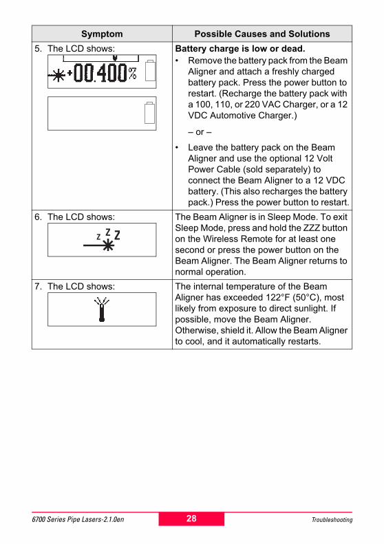
5. The LCD shows: Battery charge is low or dead.� Remove the battery pack from the Beam
Aligner and attach a freshly charged battery pack. Press the power button to restart. (Recharge the battery pack with a 100, 110, or 220 VAC Charger, or a 12 VDC Automotive Charger.)
� or �
� Leave the battery pack on the Beam Aligner and use the optional 12 Volt Power Cable (sold separately) to connect the Beam Aligner to a 12 VDC battery. (This also recharges the battery pack.) Press the power button to restart.
6. The LCD shows: The Beam Aligner is in Sleep Mode. To exit Sleep Mode, press and hold the ZZZ button on the Wireless Remote for at least one second or press the power button on the Beam Aligner. The Beam Aligner returns to normal operation.
7. The LCD shows: The internal temperature of the Beam Aligner has exceeded 122°F (50°C), most likely from exposure to direct sunlight. If possible, move the Beam Aligner. Otherwise, shield it. Allow the Beam Aligner to cool, and it automatically restarts.
Symptom Possible Causes and Solutions
28 Troubleshooting6700 Series Pipe Lasers-2.1.0en
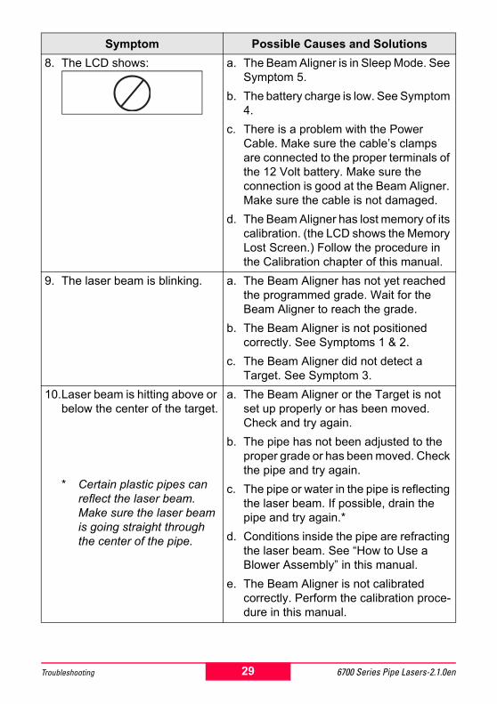
8. The LCD shows: a. The Beam Aligner is in Sleep Mode. See Symptom 5.
b. The battery charge is low. See Symptom 4.
c. There is a problem with the Power Cable. Make sure the cable�s clamps are connected to the proper terminals of the 12 Volt battery. Make sure the connection is good at the Beam Aligner. Make sure the cable is not damaged.
d. The Beam Aligner has lost memory of its calibration. (the LCD shows the Memory Lost Screen.) Follow the procedure in the Calibration chapter of this manual.
9. The laser beam is blinking. a. The Beam Aligner has not yet reached the programmed grade. Wait for the Beam Aligner to reach the grade.
b. The Beam Aligner is not positioned correctly. See Symptoms 1 & 2.
c. The Beam Aligner did not detect a Target. See Symptom 3.
10.Laser beam is hitting above or below the center of the target.
* Certain plastic pipes can reflect the laser beam. Make sure the laser beam is going straight through the center of the pipe.
a. The Beam Aligner or the Target is not set up properly or has been moved. Check and try again.
b. The pipe has not been adjusted to the proper grade or has been moved. Check the pipe and try again.
c. The pipe or water in the pipe is reflecting the laser beam. If possible, drain the pipe and try again.*
d. Conditions inside the pipe are refracting the laser beam. See �How to Use a Blower Assembly� in this manual.
e. The Beam Aligner is not calibrated correctly. Perform the calibration proce-dure in this manual.
Symptom Possible Causes and Solutions
29 6700 Series Pipe Lasers-2.1.0enTroubleshooting
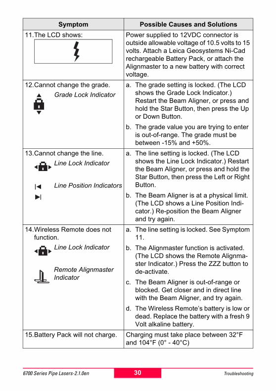
11.The LCD shows: Power supplied to 12VDC connector is outside allowable voltage of 10.5 volts to 15 volts. Attach a Leica Geosystems Ni-Cad rechargeable Battery Pack, or attach the Alignmaster to a new battery with correct voltage.
12.Cannot change the grade.Grade Lock Indicator
a. The grade setting is locked. (The LCD shows the Grade Lock Indicator.) Restart the Beam Aligner, or press and hold the Star Button, then press the Up or Down Button.
b. The grade value you are trying to enter is out-of-range. The grade must be between -15% and +50%.
13.Cannot change the line.Line Lock Indicator
Line Position Indicators
a. The line setting is locked. (The LCD shows the Line Lock Indicator.) Restart the Beam Aligner, or press and hold the Star Button, then press the Left or Right Button.
b. The Beam Aligner is at a physical limit. (The LCD shows a Line Position Indi-cator.) Re-position the Beam Aligner and try again.
14.Wireless Remote does not function.
Line Lock Indicator
Remote Alignmaster Indicator
a. The line setting is locked. See Symptom 11.
b. The Alignmaster function is activated. (The LCD shows the Remote Alignma-ster Indicator.) Press the ZZZ button to de-activate.
c. The Beam Aligner is out-of-range or blocked. Get closer and in direct line with the Beam Aligner, and try again.
d. The Wireless Remote�s battery is low or dead. Replace the battery with a fresh 9 Volt alkaline battery.
15.Battery Pack will not charge. Charging must take place between 32°F and 104°F (0° - 40°C)
Symptom Possible Causes and Solutions
30 Troubleshooting6700 Series Pipe Lasers-2.1.0en
Technical Data
Weight ...........................................................................................10 lb. (4.5 kg)Length ...................................................................................12.25 in. (310 mm)Diameter ...................................................................................5.4 in. (135 mm)Operating Temperature .............................................. -4 to 122°F (-20 to 50°C)Storage Temperature .................................................. -4 to 122°F (-20 to 50°C)Long-Term Storage Temp. .......................................... -4 to 95°F (-20 to 35°C)Operating Voltage ...................................................................... 10.5 to 15 VDCBeam Wavelength (red) ..........................................................................635 nmBeam Wavelength (green) ......................................................................532 nmWorking Range ........................................................................... 650 ft. (200 m)Grade Range ............................................................................... -15% to +50%Self-Leveling Range ..................................................................................±10%Line Range ...................................................................... 30 ft.(m) @ 100 ft.(m)Battery Pack Operation (red) ........................................................Over 30 hoursBattery Pack Operation (green) ....................................................Over 20 hours12 Volt Battery Cable (727639) ................................... fused, 3 Amp Slow Blow
Wireless Remote Range, Front ..........................................Over 500 ft. (150 m)Wireless Remote Range, Rear ...............................................Over 35 ft. (10 m)Wireless Remote Battery Op. ...............................................Approx. 12 Months
Laser Output .........................................................................4.75mW MaximumLaser Classification USA ......................................................... IIIa FDA 21 CFRLaser Classification International .............................................. 3R IEC 60825-1
31 6700 Series Pipe Lasers-2.1.0enTechnical Data
Warranty
Leica Geosystems warrants all products it manufactures to be free if defects in materials and workmanship under normal use and service for a period of 12 months, provided that the product has been properly used and cared for as stated in the User Manual. Any evidence of an attempt to repair the product by other than factory authorized personnel using Leica Geosystems certified replacement parts will automatically void the warranty.
Leica Geosystems liability under this warranty is limited to repairing or replacing any product returned to a factory authorized service facility for that purpose. The foregoing states the entire liability of Leica Geosystems in connection with the product, and they shall not be held responsible for any consequential damage of any kind. The foregoing is in lieu of all other warranties expressed or implied.
The user of the product is expected to follow all operating instructions, periodically checking the instrument and the work as it progresses. Checking and ensuring the calibration of the product is the responsibility of the user. Calibration and maintenance is not covered by the above warranty.
32 Warranty6700 Series Pipe Lasers-2.1.0en
Care and Transport
Transport
!When dispatching the product, always use the complete original Leica Geosystems packaging (case and cardboard box).When transporting the product in the field, always make sure that you:
� Either carry the product in its original transport case
� Or carry the tripod with its legs splayed across your shoulder, keeping the attached product upright.
Never carry the product loose in a road vehicle. It can be affected by shock and vibration. Always carry it in its case and secure it.
When transporting the product by rail, air or ship, always use the complete original packaging (case and cardboard box), or its equivalent, to protect it against shock and vibration.
!After transport, or after long periods of storage, inspect the field adjustment parameters given in this user manual before using the product.
Storage
! Temperature Limits (-40° to 70°C / -40° to 158°F) Respect the temperature limits when storing the product, particularly in summer if the product is inside the vehicle.
!Damp products must be unpacked. Dry the product, the case and the accessories at not more than 40°C / 108°F and clean them. Do not repack until everything is completely dry.
Cleaning and Drying Windows
!Windows� Never touch the glass with your
fingers.
� Use only a clean, soft, lint-free cloth for cleaning. If necessary, moisten the cloth with pure alcohol. Use no other liquids; these may attack the polymer components.
33 6700 Series Pipe Lasers-2.1.0enCare and Transport
Safety Directions
The following directions should enable the person responsible for the 6770/6775/6790 pipe laser system, and the person who actually uses the product, to anticipate and avoid operational hazards. The person responsible for the instrument must ensure that all users understand these directions and adhere to them.
Intended Use of Product
Permitted usesThe pipe laser system is designed and suitable for the following applications, within the limits of is intended conditions of use:
� The product casts a visible laser (red or green) beam (horizontal, tilted) for the purposes of construction.
� The product can be set up on its own leg set, on a tripod, or on an accessory trivet.
� The laser beam can be detected directly on the object being surveyed.
� The product can be powered by rechargeable NiMH batteries.
Adverse uses� Use of the product without
instruction.
� Use outside of the intended limits.
� Disabling safety systems and removal of hazard notices.
� Opening the product using tools (screwdriver, etc.).
� Modification or conversion of the product.
� Use after misappropriation.
� Use with accessories from other manufacturers without the prior express approval of Leica Geosystems GR LLC.
� Inadequate safeguards at the site (e.g. when measuring on roads, etc.).
� Deliberate dazzling of third parties.
�WARNING:Adverse use can lead to injury,
malfunction, and material damage. It is the task of the person responsible for the equipment to inform the user about hazards and how to counteract them. The laser unit is not to be used until the user has been instructed how to work with it.
Limits of UseEnvironment:Suitable for use in an atmosphere appropriate for permanent human habitation. Cannot be used in an aggressive or explosive environment. See chapter "Technical Data."
34 Safety Directions6700 Series Pipe Lasers-2.1.0en
Responsibilities Responsibility for the manufacturer of the original equipment Leica Geosystems GR LLC, Grand Rapids, MI 49546, U.S.A. (herein-after referred to as Leica Geosy-stems): Leica Geosystems is responsible for supplying the product, including the user manual and original accessories, in a completely-safe condition.
Responsibilities of the manufac-turers of non-Leica Geosystems accessories:
! The manufacturers of non-Leica Geosystems accessories for the product are responsible for developing, implementing and communicating safety concepts for their products, and are also responsible for the effectiveness of those safety concepts in combination with the Leica Geosystems product.Responsibilities of the person in charge of the equipment:
�WARNING:The person responsible for the
equipment must ensure that it is used in accordance with the instructions. This person is also accountable for the training and the deployment of personnel who use the product and for the safety of the equipment in use.
The person in charge of the equipment has the following duties:
� To understand the safety instructions on the product and the instructions in the user manual;
� To be familiar with local regulations relating to accident prevention;
� To inform Leica Geosystems immediately if the equipment becomes unsafe.
Hazards of UseMain hazards of use
�WARNING:The absence of instruction, or
the inadequate imparting of instruction, can lead to incorrect or adverse use, and can give rise to accidents with far-reaching human, material, financial, and environmental consequences.Precautions: All users must follow the safety directions given by the manufacturer and the directions of the person responsible for the equipment.
�WARNING:The charger is not designed for
use under wet conditions. If the product becomes wet it may cause you to receive an electrical shock.Precautions: Use charger only indoors, in dry rooms and protect it from damp. If the charger is damp, do not use it.
�WARNING:The charger contains potentially
haxardous voltages. Opening the charger may cause you to receive an electrical shock.Precautions: Do not open the charger.
35 6700 Series Pipe Lasers-2.1.0enSafety Directions

�CAUTION:Watch out for erroneous
measurements if the product is defective or if it has been dropped or has been misused or modified.Precautions: Periodically carry out test measurements and perform the field adjustments indicated in the user manual, particularly after the product has been subjected to abnormal use and before and after important measurements.
�WARNING:By working during a
thunderstorm you are at risk from lightning.Precautions: Do not carry out field work during thunderstorms.
�DANGER:Because of the risk of
electrocution, it is very dangerous to use staffs and telescopic scales in the vicinity of electrical installations such as power cables or electrical railways.Precautions: Keep at a safe distance from electrical installations. If it is essential to work in this environment, first contact the safety authorities responsible for the electrical installations and follow their instructions.
�WARNING:Inadequate securing of the
working site can lead to dangerous situations, for example in traffic, on building sites, and at industrial installations.
Precautions: Always ensure that the working site is adequately secured. Adhere to the regulations governing accident prevention and road traffic.
�CAUTION:During the transport or disposal
of charged batteries it is possible for inappropriate mechanical influences to constitute a fire hazard.Precautions: Remove the batteries from their compartment before they are transported. Disposal of batteries only if they are fully flat.
�CAUTION:If the accessories used with the
equipment are not properly secured and the equipment is subjected to mechanical shock (e.g. blows, falling), the equipment may be damaged or people may sustain injury.Precautions: When setting-up the equipment, make sure that the accessories (e.g. tripod, tribrach) are correctly adapted, fitted, secured, and locked in position. Avoid subjecting the equipment to mechanical shock. Never position the equipment on the tripod baseplate without securely tightening the central fixing screw. If the screw is loosened, always remove the equipment immediately from the tripod.
�WARNING:If the equipment is improperly
disposed of, the following can happen:
� If polymer parts are burnt, poisonous gases are produced which may impair health.
36 Safety Directions6700 Series Pipe Lasers-2.1.0en
� If batteries are damaged or are heated strongly, they can explode and cause poisoning, burning, corrosion, or environmental contamination.
� By disposing of the equipment irresponsibly you may enable unauthorized persons to use it in contravention of the regulations, exposing themselves and third parties to the risk of severe injury and rendering the environment liable to contamination.
Precautions: Dispose of the equipment appropriately in accordance with the regulations in force in your country. Always prevent access to the equipment by unauthorized personnel.
�WARNING:Use only the approved charger
designed for this battery pack. See manufacturer�s reference below.Precautions: Reference Friwo part no: 1807271, model no: FW1288/N for 220V. Friwo part no: 1880716, model no: FW1288 for 110V.
�CAUTION:Only Leica Geosystems
authorized workshops are entitled to repair these products.
Laser classification, 6770/6775 (red)
�WARNING:Pipe laser product produces a
visible red laser beam which emerges from the front window.
The product is a Class 3R laser product in accordance with:
� IEC 60825-1: 1993 + A1: 1997 + A2: 2001 "Radiation safety of laser products."
� EN 60825-1: 1994 + A11: 1996 + A2: 2001 �Radiation safety of laser products�
The product is a Class IIIa laser product in accordance with:
� FDA 21CFR Ch.I §1040: 2002 (US Department of Health and Human Services, Code of Federal Regulations)
Class 3R/IIIa laser products: Direct intrabeam viewing is always hazardous. Avoid direct eye exposure. The accessible emmision limit is within 5 times the accessible emission of class 2/II in the wavelength range from 400nm to 700nm.
�WARNING:Direct intrabeam viewing is
always hazardous.Precautions: Do not stare into the beam or direct it towards oher people unnecessarily. These measures are also valid for the reflected beam.
�WARNING:Looking directly into the reflected
laser beam could be dangerous to the eyes when the laser beam is aimed at areas that reflect like a mirror or emit reflections unexpectedly (e.g. prisms, mirrors, metallic surfaces, windows.)Precautions: Do not aim at areas that are essentially reflective, such as a mirror, or which could emit unwanted reflections. Do no look through or beside the optical sight at prisms or reflecting objects when the laser is switched on.
37 6700 Series Pipe Lasers-2.1.0enSafety Directions
�WARNING:The use of Laser Class 3R/IIIa
equipment can be dangerous.Precautions: To counteract hazards, it is essential for every user to respect the safety precautions and control measures specified in the standard IEC 60825-1:1993 + Am1:1997 + Am2:2000, within the hazard distance.* Pay particular attention to Section Three �User�s Guide.�
There follows here below as interpretation of the main points in the relevant section of the standard quoted.
Class 3R laser products used on construction sites and outdoors (surveying, alignment, leveling):
a) Only qualified and trained persons should be assigned to install, adjust and operate the laser equipment.
b) Areas in which these lasers are used should be posted with an appropriate laser warning sign.
c) Precautions should be taken to ensure that persons do not look directly, with or without an optical instrument, into the beam.
d) The laser beam should be termi-nated at the end of its useful beam path and should in all cases be terminated if the hazardous beam path extends beyond the limit (hazard distance *) ) of the area in which the presence and activities of personnel are monitored for reasons of protection from laser radiation.
e) The laser beam path should be located well above or below eye level wherever practicable.
f) When not in use the laser product should be stored in a location where unauthorized personnel cannot gain access.
g) Precautions should be taken to ensure that the laser beam is not unintentionally directed at mirror-like (specular) surfaces (e.g. mirrors, metal surfaces, windows). But, more importantly, at flat or concave mirror-like surfaces.
*) The hazard distance is the distance from the laser at which beam irra-diance or radiant exposure equals the maximum permissible value to which personnel may be exposed without being exposed to a health risk.
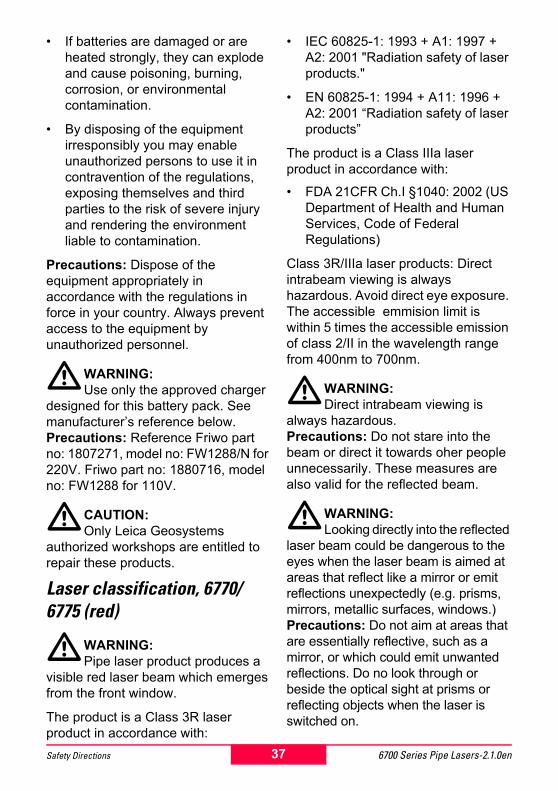
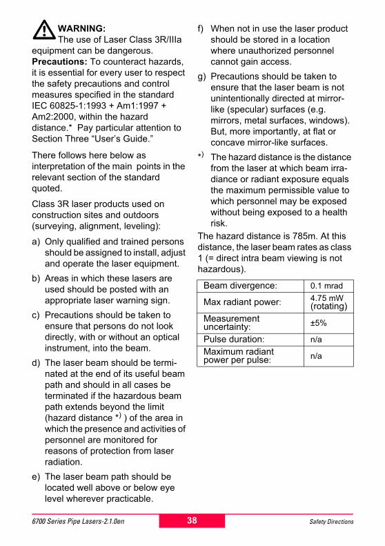
The hazard distance is 785m. At this distance, the laser beam rates as class 1 (= direct intra beam viewing is not hazardous).
Beam divergence: 0.1 mrad
Max radiant power: 4.75 mW (rotating)
Measurement uncertainty: ±5%
Pulse duration: n/aMaximum radiant power per pulse: n/a
38 Safety Directions6700 Series Pipe Lasers-2.1.0en

Labeling (6770/6775 red) Laser classification, 6790 (green)
�WARNING:Pipe laser product produces a
visible green laser beam which emerges from the front window.
The product is a Class 3R laser product in accordance with:
� IEC 60825-1: 1993 + A1: 1997 + A2: 2001 "Radiation safety of laser products."
� EN 60825-1: 1994 + A11: 1996 + A2: 2001 �Radiation safety of laser products�
The product is a Class IIIa laser product in accordance with:
� FDA 21CFR Ch.I §1040: 2002 (US Department of Health and Human Services, Code of Federal Regulations)
Class 3R/IIIa laser products: Direct intrabeam viewing is always hazardous. Avoid direct eye exposure. The accessible emmision limit is within 5 times the accessible emission of class 2/II in the wavelength range from 400nm to 700nm.
�WARNING:Direct intrabeam viewing is
always hazardous.Precautions: Do not stare into the beam or direct it towards oher people unnecessarily. These measures are also valid for the reflected beam.
6770-
Laser RadiationAvoid direct eye exposureClass 3a Laser Product
according to IEC 60825-1:1993 + A1:1997 + A2:2001
P0 ≤ 4.75 mWλ = 620 - 690 nm
39 6700 Series Pipe Lasers-2.1.0enSafety Directions
�WARNING:Looking directly into the reflected
laser beam could be dangerous to the eyes when the laser beam is aimed at areas that reflect like a mirror or emit reflections unexpectedly (e.g. prisms, mirrors, metallic surfaces, windows.)Precautions: Do not aim at areas that are essentially reflective, such as a mirror, or which could emit unwanted reflections. Do no look through or beside the optical sight at prisms or reflecting objects when the laser is switched on.
�WARNING:The use of Laser Class 3R/IIIa
equipment can be dangerous.Precautions: To counteract hazards, it is essential for every user to respect the safety precautions and control measures specified in the standard IEC 60825-1:1993 + Am1:1997 + Am2:2000, within the hazard �distance*).� Pay particular attention to Section Three �User�s Guide.�
There follows here below as interpretation of the main points in the relevant section of the standard quoted.
Class 3R laser products used on construction sites and outdoors (surveying, alignment, leveling):
a) Only qualified and trained persons should be assigned to install, adjust and operate the laser equipment.
b) Areas in which these lasers are used should be posted with an appropriate laser warning sign.
c) Precautions should be taken to ensure that persons do not look directly, with or without an optical instrument, into the beam.
d) The laser beam should be termi-nated at the end of its useful beam path and should in all cases be terminated if the hazardous beam path extends beyond the limit (hazard distance *) ) of the area in which the presence and activities of personnel are monitored for reasons of protection from laser radiation.
e) The laser beam path should be located well above or below eye level wherever practicable.
f) When not in use the laser product should be stored in a location where unauthorized personnel cannot gain access.
g) Precautions should be taken to ensure that the laser beam is not unintentionally directed at mirror-like (specular) surfaces (e.g. mirrors, metal surfaces, windows). But, more importantly, at flat or concave mirror-like surfaces.
*) The hazard distance is the distance from the laser at which beam irra-diance or radiant exposure equals the maximum permissible value to which personnel may be exposed without being exposed to a health risk.
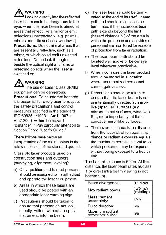
The hazard distance is 592m. At this distance, the laser beam rates as class 1 (= direct intra beam viewing is not hazardous).
Beam divergence: 0.1 mrad
Max radiant power: 4.75 mW (rotating)
Measurement uncertainty: ±5%
Pulse duration: n/aMaximum radiant power per pulse: n/a
40 Safety Directions6700 Series Pipe Lasers-2.1.0en

Labeling (6790 green) Electromagnetic Compatibility (EMC)The term "electromagnetic compatibility" is taken to mean the capability of the product to function smoothly in an environment where electromagnetic radiation and electrostatic discharges are present, and without causing electromagnetic disturbances to other equipment.
�WARNING:Electromagnetic radiation can
cause disturbances in other equipment.
Although the laser units meet the strict regulations and standards which are in force in this respect, Leica Geosystems cannot completely exclude the possibility that other equipment may be disturbed.
�WARNING:There is a risk that disturbances
may be caused in other equipment if the laser unit is used in conjunction with accessories from other manufacturers, e.g. walkie-talkies, mobile phones.Precautions: Use only the equipment and accessories recommended by Leica Geosystems. When combined with the laser unit, they meet the strict requirements stipulated by the guidelines and standards.
�CAUTION:Disturbances caused by
electromagnetic radiation can result in the tolerance limits for measurements being exceeded.
6790-
Laser RadiationAvoid direct eye exposureClass 3a Laser Product
according to IEC 60825-1:1993 + A1:1997 + A2:2001
P0 ≤ 4.75 mWλ = 532 nm
41 6700 Series Pipe Lasers-2.1.0enSafety Directions
Although the laser meets the strict regulations and standards which are in force in this connection, Leica Geosystems cannot completely exclude the possibility that the laser unit may be disturbed by very intense electromagnetic radiation, e.g. near radio transmitters, walkie-talkies, diesel generators, power cables.Precautions: Check the plausibility of results obtained under these conditions.
FCC Statement (applicable in the U.S.)
�WARNING:This equipment has been tested
and found to comply with the limits for a Class B digital device, pursuant to part 15 of the FCC rules.
These limits are designed to provide reasonable protection against harmful interference in a residential installation.
This equipment generates, uses and can radiate frequency energy and, if not installed and used in accordance with the instructions, may cause harmful interference to radio communications. However, there is no guarantee that interference will not occur in a particular installation. If this equipment does cause harmful interference to radio or television reception, which can be determined by turning the equipment off and on, the user is encouraged to try to correct the interference by one or more of the following measures:
� Increase the separation between the equipment and the receiver.
� Consult the dealer or an experienced radio/TV technician for help.
� Reorient or relocate the receiving antenna
� Connect the equipment into an outlet on a circuit different from that to which the receiver is connected.
�WARNING:Changes or modifications not
expressly approved by Leica Geosystems could void the user's authority to operate the equipment.
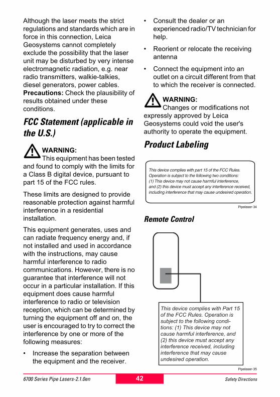
Product Labeling
Pipelaser-34
Remote Control
Pipelaser-35
42 Safety Directions6700 Series Pipe Lasers-2.1.0en
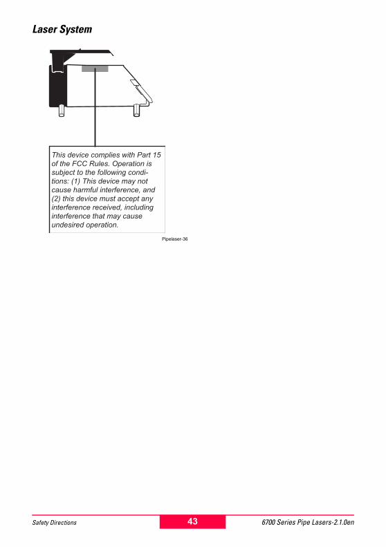
Laser System
Pipelaser-36
43 6700 Series Pipe Lasers-2.1.0enSafety Directions
Leica Geosystems GR LLCis an ISO 9001 Registered Com-pany.
Leica Geosystems GR LLC6330 28th Street SE
Grand Rapids, Michigan 49546
726480-2.1.0en
http://construction.leica-geosystems.comwww.leica-geosystems.com
Printed in SwitzerlandCopyright Leica Geosystems GR LLCGrand Rapids, Michigan, 2003(Original Text)