Embed Size (px)
Citation preview

SY
ST
EM
OV
ER
VIE
W
67797_SpectraBrochure_OP-Cindy6.0 9/24/08 2:30 PM Page 2

With the Spectra® Roadway Improvement System from
Tensar International Corporation, road design has never
been easier. Tensar® Biaxial (BX) Geogrids provide a
simple, reliable and cost-effective solution in this patented
soil reinforcement application.
The Spectra System can improve both paved and unpaved
roads by:
• Reducing required materials
• Simplifying construction
• Increasing pavement life
• Reducing future road maintenance
Even in less than ideal construction situations (i.e., weak
subgrades, heavy loads, thick fill layers, high aggregate
costs, contaminated subgrades, shallow utilities, etc.)
a predictable, engineered solution is possible with the
Spectra System. This solution relies on Tensar BX Geogrids
to provide patented soil reinforcement for unbound
aggregate layers in two distinct but related applications:
• Base Course Reinforcement – Enhances
performance or reduces the thickness of a permanent
road when constructed on a relatively firm foundation.
• Subgrade Improvement – Provides a stable
foundation layer for a permanent or temporary
road/working surface when weak subgrade
conditions (CBR < 3) are encountered.
The benefits of using the Spectra System for roadway
applications can include:
• Less aggregate
• Increased pavement life
• Less undercut
• More consistent compaction and
controlled settlement
The Spectra System has been used successfully for a
variety of projects such as: highways and secondary roads;
unpaved haul roads and working surfaces; parking areas
for commercial and industrial facilities; airport runways
and taxiways; freight truck distribution centers and
terminals; port, rail, industrial and intermodal facilities.
The Spectra® System provides a
predictable, cost-effective solution
for soil reinforcement.
Changing the Way Roads are Designed >
Tensar® Geogrids
The Spectra System owes its strength anddurability to Biaxial (BX) Geogrids, Tensar’spatented geosynthetic reinforcement grids.These geogrids stand the test of time,performing better than other commerciallyavailable geosynthetics due to their stiffinterlocking capability. For more information,visit www.tensar-international.com.
BX Geogrid awaiting installation for a project in Texas.
67797_SpectraBrochure_OP-Cindy6.0 9/24/08 2:30 PM Page 1

For aggregate reinforcement to work, it is necessary to
transfer the loads from the unbound aggregate into the
stiff geogrid. With Tensar Biaxial Geogrids, this is done
through mechanical interlock, a process where the
granular particles partially penetrate the apertures
of the geogrid and lock into place as the material
is placed and compacted (Figure 1). This process is
also often referred to as “mechanical confinement.”
Mechanical interlock can be illustrated using a billiard
ball rack (Figure 2). The rack confines the balls with
its stiffness and strength at the corners of the triangle
(i.e., the junctions). To confine the balls effectively, the
rack must have thick, squared edges. The unique process
used to manufacture Tensar BX Geogrids results in a grid
structure with full strength junctions and stiff ribs. This
presents a square, thick leading edge to the aggregate,
promoting effective mechanical interlock.
The billiard ball rack also demonstrates that effective
confinement at the aggregate section produces an
“improved zone” extending well beyond the aggregate –
geogrid interface. Roadway performance is significantly
improved as the aggregate is locked in place, yielding
a stiffer composite of pavement components.
The strength and stiffness of BX Geogrids at low strain is
critical to their performance in roadway applications. After
mechanical interlock is established during the placement
and compaction of aggregate on top of the geogrid, the
reinforcement benefits are generated at the onset of
traffic loading. The bottom line: Tensar BX Geogrids greatly
enhance the stiffness of unbound granular layers.
This results in lower cost, longer lasting and more
reliable pavements.
2
Mechanics of Aggregate Reinforcement Using BX Geogrids >
Demonstration ofmechanical interlockusing Tensar BX Geogrids
The unique structure allows the grid to get
a good “grip” on the aggregate particles and results in
effective mechanical interlock.
The unique shape of the geogrid ribs confines
aggregate particles due to its high stiffness and the strength
at the corners (junctions), just like a rack confines billiard balls.
Figure 1 Figure 2
67797_SpectraBrochure_OP-Cindy6.0 9/24/08 2:30 PM Page 2

For over two decades, Tensar® Biaxial (BX) Geogrids have
offered owners, engineers and contractors significant value
for building over soft and competent soils for a variety of
paved and unpaved surfaces. Our BX Geogrids are single
layer, integrally formed products manufactured from high
grades of polypropylene resin that exhibit high strength
at low strain and are chemically inert in practically all soil
conditions and environments. Tensar BX Geogrids exhibit
significant resistance to installation damage due to a
unique manufacturing process whereby an extruded sheet
is punched and drawn into a highly oriented grid structure.
Performance Offers Proof of Value
The performance and value of Tensar BX Geogrids have
been demonstrated over the years through full-scale
independent research and thousands of installations
worldwide. Independent agencies agree that in-ground
performance ultimately determines how geogrid products
are evaluated, approved for use and utilized for projects.
Tensar BX Geogrids have proven their value through
dozens of high profile research projects that have helped
to define the relevant civil engineering applications
whereby BX Geogrids can offer financial benefits:
• Subgrade improvement over soft soils
(both unpaved and paved surfaces)
• Base reinforcement of aggregate base course
(paved surfaces)
• Foundation improvement for shallow foundations
• Embankment stability over compressible soils
The U.S. Army Corps of Engineers concluded in 19921
through full-scale research that no single index
property, like tensile strength, is a primary indicator
of performance. Rather, the sum of these unique
characteristics predict the ability of any geogrid to
1) confine aggregate particles 2) distribute live load
(i.e., the “snowshoe effect”) and 3) span weak soils
through the tensile membrane effect.
The unique properties of
Tensar ® BX Geogrid provide
the Engineered Advantage.™
Tensar Biaxial Geogrid for Paved and Unpaved Surfaces >
PROPERTY SPECIFICATIONS FOR TENSAR® BIAXIAL GEOGRIDSIndex Properties
GEOGRID PROPERTIES TEST METHOD BX1100 BX1200 BX1300
Geometry MD CMD MD CMD MD CMD
Aperture Size I.D. Callipered 1.0 in. (25 mm) 1.3 in. (33 mm) 1.0 in. (25 mm) 1.3 in. (33 mm) 1.8 in. (46 mm) 2.5 in. (64 mm)
Open Area Measured 70% 70% 70% 70% 75% 75%
Minimum Rib Thickness Callipered 0.03 in. (0.76 mm) 0.03 in. (0.76 mm) 0.05 in. (1.27 mm) 0.05 in. (1.27 mm) 0.05 in. (1.27 mm) 0.05 in. (1.27 mm)
Junction Thickness Callipered 0.114 in. (2.9 mm) 0.114 in. (2.9 mm) 0.157 in. (4.0 mm) 0.157 in. (4.0 mm) 0.174 in. (4.4 mm) 0.174 in. (4.4 mm)
GEOGRID PROPERTIES TEST METHOD BX1100 BX1200 BX1300
Load Capacity/Structural Integrity MD CMD MD CMD MD CMD
Tensile Strength @ 2% Strain ASTM D 6637-01 280 lb/ft (4.1 kN/m) 450 lb/ft (6.6 kN/m) 410 lb/ft (6.0 kN/m) 620 lb/ft (9.0 kN/m) 380 lb/ft (5.5 kN/m) 650 lb/ft (9.5 kN/m)
Tensile Strength @ 5% Strain ASTM D 6637-01 580 lb/ft (8.5 kN/m) 920 lb/ft (13.4 kN/m) 810 lb/ft (11.8 kN/m) 1,340 lb/ft (19.6 kN/m) 720 lb/ft (10.5 kN/m) 1,200 lb/ft (17.5 kN/m)
Junction Strength GRI-GG2-01 98 lb (0.44 kN) 111 lb (0.49 kN) 151 lb (0.67 kN) 167 lb (0.74 kN) 156 lb (0.69 kN) 276 lb (1.23 kN)
Junction Effi ciency Calculated 93% 93% 93% 93% 93% 93%
Flexural Rigidity ASTM D 5732-95 250,000 mg-cm 250,000 mg-cm 750,000 mg-cm 750,000 mg-cm 450,000 mg-cm 450,000 mg-cm
Aperture Stability Modulus COE-Kinney, 2001 3.2 kg-cm/deg 3.2 kg-cm/deg 6.5 kg-cm/deg 6.5 kg-cm/deg 5.8 kg-cm/deg 5.8 kg-cm/deg
Tensar International Corporation (Tensar) reserves the right to change its product specifi cations at any time. It is the responsibility of the specifi er and purchaser to ensure that product specifi cations used for design and procurement purposes are current and consistent with the products used in each instance. Tensar warrants that at the time of delivery the geogrid furnished hereunder shall meet its published specifi cations as of the date of manufacture of the product. NO OTHER WARRANTY, EXPRESSED OR IMPLIED, INCLUDING MERCHANTABILITY OF FITNESS FOR A PARTICULAR PURPOSE, IF PROVIDED AND ANY AND ALL SUCH OTHER WARRANTIES ARE SPECIFICALLY EXCLUDED. The sole remedy to the purchaser or user of our products for breech of the above-mentioned warranty is the replacement of the geogrid material. Notifi cation of any such breech shall be made within three (3) months of product delivery and prior to installation. The applicable product specifi cation supersedes all prior specifi cations for the product. Unless indicated otherwise, values shown are minimum average roll values determined in accordance with ASTM D4759.
1Department of the Army, U.S. Army Corps of Engineers, “Geogrid Reinforced Base
Courses for Flexible Pavements for Light Aircraft: Test Section Construction, Behavior
Under Traffic, Laboratory Tests, and Design Criteria,” DOT/FAA/RD-92/25, p.26.
67797_SpectraBrochure_OP-Cindy6.0 9/24/08 2:30 PM Page 3

4
Structural Geogrid Properties – The Significance Explained >
The Flexural Rigidity Test demonstrates that Tensar
BX Geogrids are stiff and do not sag like geotextiles.
The aperture stability modulus testing apparatus
for biaxial geogrids.
Aperture Size: The inside dimension of the geogrid
openings measured with calipers. The openings must be
large enough to permit “strike through” of aggregate fill,
but small enough to ensure thorough interlocking with
aggregate particles.
Open Area: The area of openings as a percentage of the
total (horizontal) area [Percent open area is measured by
photocopying a representative specimen of geogrid laid
flat, and then adding the weights of (cut-out) pieces of
paper representing apertures and dividing this sum by
the total weight of paper]. A relatively high percentage of
the horizontal coverage area must be open to facilitate
interlocking and stress transfer between geogrid ribs
and aggregate particles.
Rib & Junction Thickness: The vertical, top-to-bottom,
dimension of the geogrid. Geogrid must be sufficiently
thick to secure aggregate particles (which strike through
the geogrid plane) in place, and thus restrict their lateral
movement. Geogrid thickness also relates to robustness;
the geogrid must be sufficiently robust to withstand heavy
earthwork construction-induced stresses to prevent
installation damage.
Secant Aperture Stability Modulus (a.k.a. TorsionalStiffness): The geogrid’s resistance to deformation under
torque – specifically a given torque (moment) of 20 cm-kg.
The test quantifies the geogrid’s capacity to maintain its
aperture configuration. Since each aperture is created by a
junction of ribs at each corner, the procedure essentially
amounts to holding a junction node and then twisting it
in its horizontal plane, as one can demonstrate with thumb
and forefingers. Torsional stiffness provides the single-best
correlation with Traffic Improvement Factor (a.k.a. Traffic
Benefit Ratio) from full-scale independent tests.
Flexural Rigidity (a.k.a. Flexural Stiffness): The geogrid’s
resistance to sag under its own weight. The test quantifies
the geogrid’s capacity to maintain its “diving-board” shape.
In the test procedure, a geogrid specimen is pushed off
the edge of a platform as a cantilever. Flexural rigidity is the
only direct measure of the so-called “snowshoe effect” of
load distribution.
Junction Strength/Efficiency: The geogrid’s capacity at
the intersections of longitudinal and transverse ribs. The
test procedure is analogous to holding one’s outstretched
arms while pulling the legs. Geogrid junctions must
efficiently transfer load from rib to rib in any direction within
the horizontal plane to be effective in load distribution.
67797_SpectraBrochure_OP-Cindy6.0 9/24/08 2:30 PM Page 4

Flexible pavement systems often fail prematurely due to
progressive lateral displacement and a weakening of the
base course. This results in rutting and eventual cracking
of the pavement surface. The Spectra System provides
confinement of the aggregate particles in the base course,
thereby maintaining structural capacity and improving the
performance of the pavement system.
Base reinforcement applications are traditionally used
with permanent roads paved with asphalt cement concrete.
In contrast with the primary application of geogrids –
improvement of weak subgrades – base reinforcement
is characterized by relatively firm subgrades with a
CBR > 3. If the subgrade is weak, an additional layer
of aggregate and BX Geogrid may be used to strengthen
it before placing the base reinforcement layers.
In base reinforcement applications, the critical failure
mechanism is lateral spreading of the base course
away from the wheel path. The inclusion of BX Geogrids
provides lateral confinement of the base to enhance
pavement performance with an increase in pavement
life, a decrease in required pavement thickness or
a combination of the two (Figure 3).
Reduce Component Thickness
BX Geogrids can reduce the base thickness required to
support a specified amount of heavy traffic by as much
as 25% to 50%.
In a trial conducted by the Wyoming Department of
Transportation, two test sections of a state highway
were monitored for performance. The control section
was designed to carry 310 ESAL’s per day for a 20-year
design life. The adjacent test section’s base thickness
was reduced by one-third, and Tensar BX1100 Geogrid
was installed at its base-subgrade interface.
Using a falling weight deflectometer (FWD) to measure the
rut depth at the surface and the surface deflection, the
relative performance of the two test sections was found to
be virtually identical after a three-year period (Figure 4).
Increase Pavement Life
Numerous trials have been conducted to assess the
benefits of using BX Geogrids in base reinforcement
applications. In these trials, the performance of an
unreinforced control section was compared after
Base Reinforcement >
The Spectra System
extends the life
of a roadway by
providing confinement
and maintaining
structural capacity.
Figure 3
AsphaltAggregate
Base Course
SubgradeUnreinforced –Aggregate moveslaterally under traffic loading.
Reinforced – Aggregateis confined in the zoneimmediately above the BX Geogrid andtherefore lateralmovement is reduced.
Asphalt Concrete
Granular Fill or Subbase
Tensar BX
Geogrid
Aggregate BaseAggregate Base
The Spectra System is used to improve the subgrade, to reinforce the base course, or do both. Shown here are typical placement elevations for Tensar BX Geogridsbeneath paved roadways.
Subgrade
67797_SpectraBrochure_OP-Cindy6.0 9/24/08 2:30 PM Page 5

Traffic Benefit Ratio (TBR)
trafficking to the performance of a section that included
a geosynthetic.
When addressing extension of pavement life, it is
necessary to consider the traffic benefit ratio (TBR).
TBR is defined as the ratio of cycles-to-failure in a geogrid-
reinforced section compared with an unreinforced section
of the same thickness. As indicated in independent,
full-scale testing conducted by a number of research
entities, the TBR varies significantly with different geogrids.
Once the TBR has been determined for a specific
geogrid, it can be multiplied by the design ESAL’s for
an unreinforced pavement section to determine the
performance of that section when a geogrid is included.
For relatively thin aggregate base sections, the geogrid
is normally placed at the bottom of the layer; for thicker
bases (10 inches or greater), it is placed toward the center
of the layer.
Retention of Stiffness
The biaxial geogrid within a reinforced pavement is able
to maintain the stiffness characteristics of the aggregate
base throughout the life of the pavement structure. This
enables the base layer to be modeled with mechanistic
design methods to ensure the service life of the structure.
With full-scale research and empirical data collected from
projects, stiffness retention has been demonstrated to
be a vital feature of base reinforcement applications.
The confinement mechanism unique to biaxial geogrid
reinforcement captures the residual stress of the aggregate,
resulting in a base layer modulus that is maintained
throughout the life of the pavement structure. This results
in longer lasting pavements and lower maintenance costs.
Proven Through Research and in the Field
The Spectra Roadway Improvement System has been
studied for base reinforcement applications for over
20 years. It can also handle the toughest test of all for base
reinforcement – real world performance. Tensar BX Geogrids
have been used by the FHWA, state DOTs, local county and
municipality agencies, and private owners and developers,
consistently demonstrating their economic and structural
value. Without question, the Spectra System has proven
its reliability in a variety of conditions time and time again.
6
0.79 in. friction course
4 in. hot mix
granular base
Subgrade(CBR = 4)
11 in.
17 in.
ControlSection
TensarBX1100
Wyoming Department of Transportation Designed for 310 ESAL’sper day for 20 years
0.20
0.15
0.10
0.05
0
With BX1100
Control
Measured performanceafter 3 years in service
0.116 in.
0.013 in.
Rut Depth
Measurement method
Defl
ecti
on/R
utin
.
FWD Deflection
0.012 in.
0.123 in.
Number of passesin reinforced section
Number of passesin control section
DeformationControl
200 600
Number ofpasses
Reinforced1.0 in.
0.50 in.
600= = 3
200TBR for 1 in. =deformation
Comparison of unreinforced and reinforced pavements in Wyoming.Figure 4
67797_SpectraBrochure_OP-Cindy6.0 9/24/08 2:30 PM Page 6

Empirical data reveals three distinct features that
Tensar® BX Geogrids provide in base reinforcement
of flexible pavements:
• Reduction in pavement components
• Extension of service life
• Retention of stiffness over time
University of Illinois at Urbana-Champaign
A full-scale accelerated pavement test was conducted at
the University of Illinois at Urbana-Champaign, under the
direction of Dr. Imad L. Al-Qadi and Dr. Erol Tutumluer, to
evaluate the performance of Tensar Geogrids in pavements.
The study’s main objective was to develop a mechanistic
analysis model for inclusion of geogrids in flexible
pavements by testing full-scale pavement sections and
measuring the pavement’s response to loading using
pavement instrumentation.
Nine instrumented, full-scale flexible pavement test
sections were designed and built to evaluate and quantify
the effectiveness of geogrid reinforcement. The sections
were divided into three categories based on the total
thickness of the pavement system structure.
The UIUC research revealed that the presence of geogrid
in the reinforced sections had a pronounced impact on
the response and performance of the base course in
comparison with the unreinforced section. The incremental
improvement demonstrated by the geogrid-reinforced
sections validated the assumption that the degree of
enhancement offered by base reinforcement varies with:
• Aggregate thickness
• Asphalt thickness
• Subgrade support
• Aggregate quality
• Geogrid type and placement
• Moisture, traffic and other factors
The research resulted in the development of a mechanistic
model through which the incremental benefit associated
with Tensar Geogrid reinforcement can now be reliably
predicted. These findings aid in validating historical and
empirical full-scale research, which continues to set the
foundation for base reinforcement applications throughout
the world.
Base Reinforcement (continued) >
The University of Illinoisused the AcceleratedTransportation LoadingSystem (ATLAS) to testthe effectiveness ofTensar® BX Geogrid. The responses of thepavement sectionswere then measured.
The post-trafficked trench
section (on the right)
reveals a dramatic
reduction in asphalt and
aggregate deformation
due to the inclusion
of Tensar BX Geogrid
when compared to the
unreinforced section
pictured on the left.
Fatigue CrackingPavement
Deformation
Reinforced with
BX Geogrid
67797_SpectraBrochure_OP-Cindy6.0 9/24/08 2:30 PM Page 7

8
Distance from load centerline (mm)
-400 -200 0 200 400
Dyn
amic
sur
face
de
form
atio
n (m
m) 3
2
1
0
ControlWoven GeotextileTensar BX
Cycle number0 50000 100000 200000
Dyn
amic
ver
tica
l str
ess
(kPa
)
80
60
40
20
0
ControlTensar BX
Figure 5 Figure 6
0.9
Grid M Grid T Control Grid F
14 in. Aggregate Base
Grid C BX1100 BX1200
0.9 1.0 1.1
1.6
2.7
4.7
Subgrade (CBR = 3)
Traf
fic B
enefi
t Rat
io
Results from a U.S. Army Corps of Engineers Trial
5
4
3
2
1
0
2 in. Asphalt Concrete
Pavement Section
U.S. Army Corps of Engineers
In 1990 and 1991, the U.S. Army Corps of Engineers,
on behalf of the Federal Aviation Administration (FAA),
investigated geogrid-reinforced base courses for flexible
pavements used by light aircraft (prior research used tank
and truck loadings). This investigation involved full-scale
field-testing of reinforced pavement sections using a
30,000-pound single-tire load. The objective of the
research was to determine the traffic benefit ratio (TBR)
for flexible pavements for light aircraft.
Surface deformation measurements were periodically
taken after a specified number of load cycles for each test
section. The test sections consisted of two inches of
asphalt, 14 inches of base aggregate and a subgrade CBR
of 3%. The TBR at one-inch deformation for Tensar BX1100
Geogrid and Tensar BX1200 Geogrid was 2.7 and 4.7,
respectively. The TBR for the other commercially available
geogrids tested varied from 0.9 to 1.6. These results
confirmed that the inclusion of Tensar BX Geogrids
significantly enhanced the performance of flexible
pavements which led the FAA to draft a performance-
based specification that captured the necessary physical
properties for geogrid to enhance performance.
Montana State University – Bozeman
From 1996–1999, Montana Department of Transportation
researchers were tasked with providing experimental data
that could be used to further identify the mechanisms
of geosynthetic reinforcement that lead to enhanced
pavement performance. A small-scale stationary plate
was used to distribute stress to an asphalt-aggregate-
subgrade system; Tensar BX Geogrid, geotextile and a
control section were all tested to monitor deformation
at the surface during and after loading.
This study clearly demonstrated Tensar BX Geogrid’s
reinforcement and confinement mechanism associated
with base reinforcement applications. The stiffness of the
aggregate layer was enhanced as a result of the geogrid
placement at the base-subgrade interface; dynamic surface
deformations were reduced by a factor of nearly 3.0
(Figure 5). In addition, the stiffness retention mechanism
was demonstrated through stress measurements taken
within the subgrade, indicating that Tensar BX Geogrid
greatly reduced the load influence over repeated load
cycles in comparison with the control section (Figure 6).
67797_SpectraBrochure_OP-Cindy6.0 9/24/08 2:30 PM Page 8

Expedient – But Efficient?
Phased construction has become a common practice in
recent years, particularly in residential developments, in
order to gain site access quickly. With phased construction,
contractors build a roadway, first placing a layer of
aggregate followed by an asphalt base. Once overall site
construction is complete, the remaining asphalt surface
course is applied.
The process may be expedient, but it’s not always
structurally efficient; phased construction can result in an
80% reduction in trafficking capacity of the finished road,
leading ultimately to premature road failure. Since a
roadway is subjected to its most punishing traffic during
site construction, surface cracking can begin to appear
within a year of its completion, most commonly in the form
of “alligator cracking.” Once cracking begins, deterioration
accelerates quickly. The problem is literally below the
surface, deep within the pavement structure, and standard
surface rehabilitation measures will not resolve it.
BX Geogrids Increase Capacity, Improve Long-Term Performance
These three pavement section diagrams, reflecting current
AASHTO methods for the design of flexible pavements,
illustrate the benefits of using Tensar BX1200 Geogrid
during phased construction. An unreinforced roadway
(Figure 8) can lose 80% of its trafficking capacity as a
result of phased construction. But a roadway reinforced
with BX1200 Geogrid (Figure 9) during phased
construction can outperform an unreinforced roadway with
its final asphalt surface layer applied (Figure 7). Clearly,
reinforcement with Tensar BX1200 Geogrid is the cost-
efficient alternative, providing exceptional performance
both during phased construction and throughout the
service life of the pavement.
Phased Construction of Asphalt Pavements >
Tensar BX Geogrids add performance
and cost efficiencies to today’s
phased construction practices.
Unreinforced pavement during phased
construction (10,000 ESAL’s)
Pavement reinforced with BX1200
Geogrid during phased construction (60,000 ESAL’s)
Traffic capacities calculated with SpectraPave3™
Software using current AASHTO design guidelines.
Figure 8 Figure 9Unreinforced finished pavement
(55,000 ESAL’s)
Figure 7
67797_SpectraBrochure_OP-Cindy6.0 9/24/08 2:31 PM Page 9

Creating a Uniform Subgrade Elevation
Uneven Elevations Compromise PerformancePavement sections at large retail store developments
are typically designed to accommodate both heavy-duty
(delivery trucks) and light-duty (shoppers) trafficking
conditions. The need to install thicker layers of asphalt or
unreinforced aggregate in heavy-duty sections can result in
aggregate-subgrade interfaces at lower depths (Figure 10)
relative to the light-duty section.
This may cause a number of problems. Of greatest
significance, water entering the pavement can accumulate
in these recesses. As a result, subgrade strength will
diminish as the base becomes saturated, leaving the
pavement weaker in areas where the greatest strength
is required.
BX Geogrids: the Uniform SolutionBy reducing required aggregate and asphalt thicknesses,
Tensar BX Geogrids can be used to create a uniform
subgrade elevation for both heavy-duty and light-duty
pavement sections (Figure 11), resulting in a number
of engineering and economic benefits:
• Settlement of water into deeper recesses of heavy-
duty sections is eliminated, maintaining pavement
strength and reducing the possibility of freeze-thaw.
• Light-duty sections better withstand unexpected
loads from delivery trucks and other heavy traffic.
• Construction is simplified with reduced stake-out
procedures, soil excavation and disposal.
• Fewer materials and quicker construction save
overall project time and expense.
By creating a uniform subgrade elevation, Tensar
BX Geogrids significantly improve the performance
of pavement sections throughout larger retail
store developments.
Large Retail Store Developments >
10
Tensar BX Geogrids create
uniform surfaces for light-duty and
heavy-duty pavements common
to retail developments.
1.5 in. ACC Surface 1.5 in. ACC Surface1.5 in. ACC Surface
3 in. ACC Base 3 in. ACC Base4 in. ACC Base
9 in. Aggregate etagerggA .ni 9etagerggA .ni 9
Subgrade SubgradeSubgrade
Standard Duty Heavy Duty Standard Duty
142,000 ESAL’s 321,000 ESAL’s 142,000 ESAL’s
1.5 in. ACC Surface 1.5 in. ACC Surface1.5 in. ACC Surface
3 in. ACC Base 3 in. ACC Base3 in. ACC Base
6 in. Aggregate etagerggA .ni 6etagerggA .ni 6
Subgrade SubgradeSubgrade
BX1200 Geogrid dirgoeG 0011XBdirgoeG 0011XB
Standard Duty Heavy Duty Standard Duty
165,000 ESAL’s 330,000 ESAL’s 165,000 ESAL’s
Pavement section reinforced with BX Geogrids
Traffic capacities calculated using current AASHTO design
guidelines; for details, consult current (1993) Design Guide
and Interim Standard PP 46-01.
Figure 11Unreinforced pavement section.Figure 10
67797_SpectraBrochure_OP-Cindy6.0 9/24/08 2:31 PM Page 10

Weak foundation soils (subgrades) are a common problem
in road construction. This could be a short-term issue
if constructing a temporary access road, or a long-term
problem if a permanent road is built over a soft subgrade.
In either case, large deformation of the subgrade will lead
to a rapid deterioration of the paved or unpaved surface.
The interlocking action of aggregate and Tensar BX Geogrids
results in a stiffened granular platform. This platform
enhances load distribution, much like a snowshoe
distributes a person’s weight evenly over soft snow. This
“snowshoe effect” generated from BX Geogrids reduces
the stress applied to the subgrade (Figure 12).
Improve Site Access
BX Geogrids provide access to a site even in the most
severe soft soil conditions. The geogrid is simply rolled
out with a layer of granular fill over the top resulting in a
free-draining working platform or a reliable access road.
Reduce Aggregate
In test after test, Tensar BX Geogrids have shown their value.
They enable a thinner layer of fill to be used with the same
capacity and serviceability as a thicker unreinforced layer.
Generally, the fill reduction is between 40% and 60%
(Figure 13). The Giroud-Han Design Method discussed on
pages 13 and 15 outlines the approach to determine the
required granular fill thickness.
Reduce Undercut and Backfill
Removing contaminated or poor quality soil is expensive –
especially when disposal to a licensed landfill is necessary.
An additional benefit of the reduced aggregate thickness
described above is that the amount of undercut is also
reduced. This results in savings of both time and money.
Subgrade Improvement >
By creating a stiffened platform
and evenly distributing load,
BX Geogrids reduce the stress
applied to the subgrade.
By using BX Geogrids the unbound aggregate can be
reduced by about 40% to 60%.
Unreinforced
Vertical pressurewithout Geogrid
Vertical pressurewith Geogrid
Reinforced
Soft Subgrade
Tensar GeogridSub-base
Granular Fill
Figure 13Snowshoe Effect – Tensar BX Geogrids distribute heavy
loads over soft soils just like a snowshoe supports the weight of a man
over soft snow.
Figure 12
67797_SpectraBrochure_OP-Cindy6.0 9/24/08 2:31 PM Page 11

A Cost-Effective Alternative to Chemical Stabilization
When chemical stabilization (lime, cement, etc.) is being
considered for a particular project, BX Geogrids provide a
cost-effective alternative with several advantages such as:
• Simple design procedures
• Easy installation (no skilled labor required)
• Better drainage
• No environmental concerns
• Immediate results (no curing period)
Reduced Maintenance
Tensar BX Geogrids are reliable and consistent. With
a reduced load spread evenly over highly variable
subgrades, compaction tends to be more uniform than
when no reinforcement is used. This leads to decreased
maintenance and repair costs both during construction
and over the life of the roadway.
Simple Installation
Installation of BX Geogrids is quick and simple. They are
supplied in lightweight rolls that are easy to handle and
cut in the field. They easily adapt to curves in the roadway,
utility projections and other unforeseen site obstructions.
“Stiffer is Better”
Tensar Biaxial Geogrids are stiff – they have high strength
in two directions. In fact, in Report DOT/FAA/RD–92-25,
sponsored by the USDOT/FAA, researchers at the U.S.
Army Corps of Engineers Waterways Experiment Station
(WES) concluded that, in evaluating geogrids “Stiffer
is better.” It’s this rigidity that outperforms other
commercially available geogrids. Over weak subgrades,
Tensar BX Geogrids distribute loads over a larger area,
reducing the pressure on the subgrade.
To keep weak soils from becoming a problem, choose
Tensar BX Geogrids for subgrade improvement
applications. BX Geogrids distribute loads more efficiently,
increase the effective bearing capacity of the subgrade,
reduce rutting and provide a better alternative to costly,
conventional stabilization methods.
12
67797_SpectraBrochure_OP-Cindy6.0 9/24/08 2:31 PM Page 12

Subgrade Improvement Design Using The Giroud-Han Design Method
The most significant advancement in geosynthetic-
reinforced road design in the last 20 years was published
by Drs. J.P. Giroud and Jie Han in the August 2004 edition of
the ASCE Journal of Geotechnical and Geoenvironmental
Engineering. Their approach combines bearing capacity
theory, empirical data from full-scale test sections and
monitored in-service roads.
The major advantages of using the Giroud-Han method are:
• Consideration of the effects of variation in base
course strength.
• Consideration of the number and size of load cycles
(axle passes) and the desired roadway performance.
• Consideration of how the load distribution angle
within the base course changes with time.
• Recognition that geotextiles and geogrids perform
differently in roads.
• Recognition that not all geogrids perform the same,
and that geogrid index properties can be used to
predict how a particular material will perform.
• Calibration and validation of the theoretical results
with laboratory and full-scale test data.
This new method facilitates the most accurate, reliable
and cost effective determination of the required aggregate
thickness for unpaved roads or working platforms when
designing with geogrid, geotextiles or aggregate only.
It has revolutionized how unpaved roads are designed
in subgrade improvement applications.
Subgrade Improvement Design Using theU.S. Army Corps of Engineers’ Method
In February 2003, the U.S. Army Corps of Engineers
published ETL 1110-1-189 titled, Use of Geogrids in
Pavement Construction.Their approach, based on the
methodology originally developed by the U.S. Forest
Service, distinguishes the performance of geotextiles
and geogrids as reinforcement components in subgrade
improvement applications.
The required aggregate thickness values determined using
the Corps’ design method are in general agreement with
those determined using the Giroud-Han method. However,
the latter provides more flexibility and therefore allows the
designer to consider a much wider range of design parameters.
Design Methods>
Quantifying the features
of Tensar BX Geogrids for
paved and unpaved surfaces.
The Giroud-Han Design Methodology, a
significant advancement in unsurfaced
roadway design, was published in the
ASCE Journal of Geotechnical andGeoenvironmental Engineering.
67797_SpectraBrochure_OP-Cindy6.0 9/24/08 2:31 PM Page 13

Base Reinforcement Design Using AASHTO Guidelines
Guidance for the design of flexible pavements is provided
in the current AASHTO (1993) Flexible Pavement Design
Guide. The AASHTO approach uses the thickness, layer
coefficient and drainage factor for each pavement
component to obtain an overall structural number. This
is then considered along with other parameters such
as defining the subgrade strength and level of reliability
required to obtain an allowable trafficking level (ESAL’s)
for a particular pavement section.
Geogrids can be included in a flexible pavement design by
referring to the method prescribed in AASHTO’s Provisional
Standard PP 46-01, “Recommended Practice for
Geosynthetic Reinforcement of the Aggregate Base Course
of Flexible Pavement Structures.” The allowable traffic load
determined for the unreinforced pavement is multiplied by
an appropriate traffic benefit ratio (TBR). The TBR value
used for a particular geogrid must be developed through
evaluation of the product in full-scale test sections.
The magnitude of the TBR determined in such tests
varies depending on several factors such as type of
geogrid and the overall geometry of the pavement
section being considered.
This empirical approach is the standard of practice
for base reinforcement design. However, new, more
accurate mechanistic-empirical design methods
incorporating BX Geogrids are currently being developed.
See page 7 for results from a study conducted by the
University of Illinois at Urbana-Champaign that validated
the new mechanistic-empirical model for designing
flexible pavements with Tensar® BX Geogrids.
Base Reinforcement Design Using the Kentucky Transportation Cabinet’sMethodology
In an adaptation of AASHTO’s methodology, the Kentucky
Transportation Cabinet’s (KYTC) Design Memorandum
Ref. 17-04, published in December 2004, describes an
approved method for inclusion of geogrids in base
reinforcement applications.
Using this approach, the target structural number for
a given number of ESAL’s is reduced in pavement sections
that contain geogrid reinforcement. The effect of the
geogrid’s inclusion is evident – the thickness of the
pavement section can be reduced with no performance
loss (Figure 14).
14
Control SectionTarget SN = 5.72
6 in.
23 in.
ACC
ABC
ACC
ABC
ACC
ABC
6 in.
18 in.
6 in.
14.5 in.
BX1100Target SN = 5.02
BX1200Target SN = 4.50
Equivalent Designs
for 5 million ESAL’s,
Subgrade CBR = 6
based on the
Kentucky
Transportation
Cabinet’s Design
Methodology.
With a reduced target
structural number, the
pavement section can
be reduced with no
performance loss.
Figure 14
ACC = Asphalt Cement Concrete
ABC = Aggregate Base Course
67797_SpectraBrochure_OP-Cindy6.0 9/24/08 2:31 PM Page 14

Cost Benefits of Tensar Biaxial Geogrids >
Tensar BX Geogrids prove
their value time and time again.
0.868 + (0.661 – 1.006J2)
1 + 0.204
logN PRr2
h = – 1
– 1 1–0.9e Nc Fc CBRsg
r
1.5rh
sfs
3.48CBRbc0.3
CBRsg
r
h
2
The cost savings offered by Tensar Biaxial Geogrids used
in conjunction with unpaved surfaces over soft soils are
realized through the Giroud-Han design method entitled,
“Design Method for Geogrid-Reinforced Unpaved Roads.”
Many owners, engineers and contractors recognize the
value of BX Geogrids through the aggregate reduction
calculated using this state-of-the-art design equation.
A review of the design equation and an example of this
method and the value offered by BX Geogrids are
discussed below.
Giroud-Han Method Equation
This method predicts the required fill thickness for an
unpaved surface based on live loading, subgrade support
and a prescribed level of serviceability. The equation for
the determination of unreinforced and geogrid reinforced
fills over soft soils per the Giroud-Han Method is shown:
Where:h = base course thickness (in./mm)
P = wheel load = axle load/2
J = aperture stability modulus of the geosynthetic
(m-N/degree)
Junreinforced = 0 JBX1100 = 3.2
Jgeotextile = 0 JBX1200 = 6.5
r = radius of the equivalent tire contact
area (meters)
CBRbc= aggregate CBR
CBRsg = subgrade CBR
N = number of axle passes
s = maximum rut depth (mm)
fs = rut depth factor = 75 (when s quoted in mm)
fc = factor relating CBR of subgrade to
equivalent cu value
Nc = bearing capacity factor
Nc–unreinforced = 3.14 Nc–geotextile = 5.14
Nc–geogrid = 5.71
cu = undrained cohesion of subgrade soil (kPa)
The equation is solved iteratively until the value base course thickness,
h, is determined.
67797_SpectraBrochure_OP-Cindy6.0 9/24/08 2:31 PM Page 15

Example Problem
A haul road is needed to accommodate 400 passes of a
3-axle dump truck, with axles carrying 20,000 lbs apiece
and tires inflated to 100 psi. The subgrade soil, fill
material, and serviceability of the road (rut depth) are
characterized below:
• Subgrade Soil = Medium/Stiff Consistency
• Measured Subgrade CBR = 1.6
• Aggregate Fill CBR = 80
• Allowable Rut Depth = 1.5 inches
• Aggregate Cost (installed) = $20.00/ton
Determine cost savings per unit area (SY) with a Tensar®
Biaxial Geogrid and a woven geotextile.
16
$150,000
$100,000
$50,000
$0
1.000 1.25 1.50 1.75 2.00 2.25 2.50 2.75 3.00
Cost Savings vs. Subgrade CBR
Subgrade CBR
$ S
avin
gs/
Runnin
g M
ile
Tensar BX1200 Tensar BX1100 Woven Geotextile
Typical cost savings per running mile of a 20 ft wide permanent haul road. Aggregate Cost = $20.00/ton in-place.
Example of cost savings realized by a BX Geogrid reinforced haul
road compared to an unreinforced and geotextile section.
Figure 15
Solution:For 1,200 axles passes (400 x 3 = 1,200),
thicknesses yielded from the Giroud-Han Method,
solving iteratively for “h” are:
• Unreinforced: 24 inches
• With Tensar BX1200: 11 inches
• With Tensar BX1100: 15 inches
• With Woven Geotextile: 18 inches
For the given example, the savings offered by
Tensar BX1200, BX1100 and a woven geotextile are:
• With Tensar BX1200: 24 - 11 = 13 inches
• With Tensar BX1100: 24 - 15 = 9 inches
• With Woven Geotextile: 24 - 18 = 6 inches
Based upon an in-place aggregate cost of $20.00/ton, the
corresponding unit price per SY-inch of stone is $1.00. That is,
for every inch of fill reduced by the geosynthetic relative to the
unreinforced design, the end user will realize a $1.00/SY savings.
Therefore, the cost savings realized for each product is:
• Tensar BX1200 = $13.00/SY minus in-place cost for the geogrid
• Tensar BX1100 = $9.00/SY minus in-place cost for the geogrid
• Woven Geotextile = $6.00/SY minus in-place cost for the geotextile
See Figure 15 for an example of how Tensar BX Geogrids offer the
highest cost savings.
For pricing information on Tensar Biaxial Geogrids or to find a local
stocking distributor, please call 1-800-TENSAR-1.
Assumed Aggregate Unit Weight:
AGGREGATE IN-PLACE COST CONVERSION CHART
$/TON $/CY $/SY-in. $/TON $/CY $/SY-in.
$ 5.00 $ 8.98 $ 0.25 $ 22.00 $ 39.50 $ 1.10
$ 6.00 $ 10.77 $ 0.30 $ 23.00 $ 41.29 $ 1.15
$ 7.00 $ 12.57 $ 0.35 $ 24.00 $ 43.09 $ 1.20
$ 8.00 $ 14.36 $ 0.40 $ 25.00 $ 44.88 $ 1.25
$ 9.00 $ 16.16 $ 0.45 $ 26.00 $ 46.88 $ 1.30
$ 10.00 $ 17.95 $ 0.50 $ 27.00 $ 48.47 $ 1.35
$ 11.00 $ 19.75 $ 0.55 $ 28.00 $ 50.27 $ 1.40
$ 12.00 $ 21.54 $ 0.60 $ 29.00 $ 52.06 $ 1.45
$ 13.00 $ 23.34 $ 0.65 $ 30.00 $ 53.86 $ 1.50
$ 14.00 $ 25.13 $ 0.70 $ 31.00 $ 55.66 $ 1.55
$ 15.00 $ 26.93 $ 0.75 $ 32.00 $ 57.45 $ 1.60
$ 16.00 $ 28.73 $ 0.80 $ 33.00 $ 59.25 $ 1.65
$ 17.00 $ 30.52 $ 0.85 $ 34.00 $ 61.04 $ 1.70
$ 18.00 $ 32.32 $ 0.90 $ 35.00 $ 62.84 $ 1.75
$ 19.00 $ 34.11 $ 0.95 $ 36.00 $ 64.63 $ 1.80
$ 20.00 $ 35.91 $ 1.00 $ 37.00 $ 66.43 $ 1.85
$ 21.00 $ 37.70 $ 1.05 $ 38.00 $ 68.22 $ 1.90
67797_SpectraBrochure_OP-Cindy6.0 9/24/08 2:31 PM Page 16

Natural Filtration of Confined Aggregate
Separation is a term used to describe the ability of a
geosynthetic to restrain fine soil particles from migrating
into a courser overlying fill due to the presence of excess
moisture and pressure. This “contamination” phenomenon
is a common issue when building over soft soils. Common
sense might suggest that geogrids, because of their
apertures, cannot provide effective separation when
placed between aggregate fill and a soft, fine subgrade.
However, this is not the case. Testing and experience
have shown that stiff BX Geogrids do facilitate separation.
When properly graded aggregate fill is used, the aggregate
performs as a “natural filter.”
Implications of Routinely UsingGeotextiles for Separation
When geotextiles are used to construct roads over soft
soils, there is often no consideration of the consequences
of this action – the “blinding out” or clogging that may
occur as fine particles migrate into the geotextile layer.
Tensar BX Geogrids do not clog, but allow moisture
to move through their apertures, thus expediting the
consolidation of the underlying weak subgrade material.
Evidence That Separation Can Indeed Be Achieved Using Geogrid
Identical pavement sections using two different
BX Geogrids and a geotextile were constructed in a study
undertaken for the FHWA in the Department of Civil
Engineering at Montana State University; full results of
the study can be found in the report ref. FHWA/MT-99-
001/8138. The subgrade consisted of high plasticity clay
mixed and placed to attain a CBR value of 1.5. The study
concluded that, “For all test sections, mixing of the
subgrade and base course aggregate was not observed.”
A similar study was undertaken on behalf of the U.S.
Department of Transportation and the Federal Aviation
Administration and performed at the U.S. Army Corps of
Engineers Waterways Experiment Station Geotechnical
Laboratory (DOT/FAA/RD-92/25). Similar findings were
reported, “The BX Geogrid confines the subgrade material
below the base, preventing or limiting the amount of
subgrade rutting upheaval from penetrating into or
through the base material. Without geogrid confinement,
rutting upheaval can penetrate through the base layer.”
At a major truck parking lot, the opportunity arose to
excavate and inspect the condition of an unbound roadway
Separation >
Tensar BX Geogrid reinforced
aggregate provides effective
separation by using the natural
filtration properties of the
granular fill.
After 11 years of traffic in a truck parking lot, the boundary between the base and subgrade
remains distinct. Stiff Tensar BX Geogrid was the only material used to separate these materials.
Figure 16
67797_SpectraBrochure_OP-Cindy6.0 9/24/08 2:31 PM Page 17

following 11 years of heavy traffic. The original subgrade
consisted of a soft organic soil; a BX Geogrid had been
placed at the interface between the weak subgrade and
overlying aggregate. It can be seen in Figure 16 that the
interface is distinct, and there is no evidence of upward
pumping of the subgrade or downward migration of the
aggregate. It can also be seen that the geogrid itself
is flat and level.
Natural Separation Mechanism
In order to understand the mechanism that causes
separation, we can consider how a sieve functions. A - in.
sieve does not allow soil particles smaller than - in. to
pass through unless the sieve itself is vibrated. BX Geogrids
interlock with aggregate fill and inhibit movement at the
base-subgrade interface, preventing the movement of soil
particles, which causes the subgrade to “pump” up into the
aggregate. Without lateral or vertical movement, well-graded
aggregate base material can form a natural filter and
prevent pumping from occurring, keeping the base aggregate
uncontaminated (Figures 17 and 18). In addition, the pressure
reduction, which results from the snowshoe effect, helps to
reduce pore water pressures in the subgrade. This results in
a reduced driving force to maintain the movement of fines
up into the base material.
18
LEGEND:
In-place soil
D85 soilentrapped in filter
Soil migrated intofilter, held by D85size soil particles
Spherical particle “B” willjust pass through porespace between the threespheres. “A” = 6- timesthe diameter of “B.”
A
B
Particle Sizes Fundamentalto Piping Ratio Concept
D15 (filter)
D85 (subgrade)
Water Movement
Subgrade Nominal boundarybefore movement
Preventing Pumping with Natural Filters
Figure 17
Figure 18
The storage yard for
Tensar’s manufacturing
plant in Morrow, GA,
rests on “Georgia Red
Clay” topped by a
Tensar® BX Geogrid and
crushed aggregate.
67797_SpectraBrochure_OP-Cindy6.0 9/24/08 2:31 PM Page 18

It is possible to calculate whether a filter is required when
considering a BX Geogrid for the reinforcement of an
unbound aggregate layer. The potential for “pumping”
to occur between two materials can be determined by
calculating the Piping Ratio (as defined below). In order
to prevent “pumping,” it is necessary that the Piping Ratio
is less than 5.
Piping Ratio =
Where • D15 Filter = the grain size of the smallest
15% of the base aggregate or granular fill
• D85 Subgrade = the grain size of the largest
85% of the subgrade soil
Low plasticity subgrades consisting of silt or very fine sand
are inherently more mobile in moist conditions than clay
subgrades. When these soils are present, it is necessary
to undertake an additional filter check:
Average Size Ratio =
Where • D50f = the average grain size
of the base aggregate
• D50s = the average grain size
of the subgrade soil
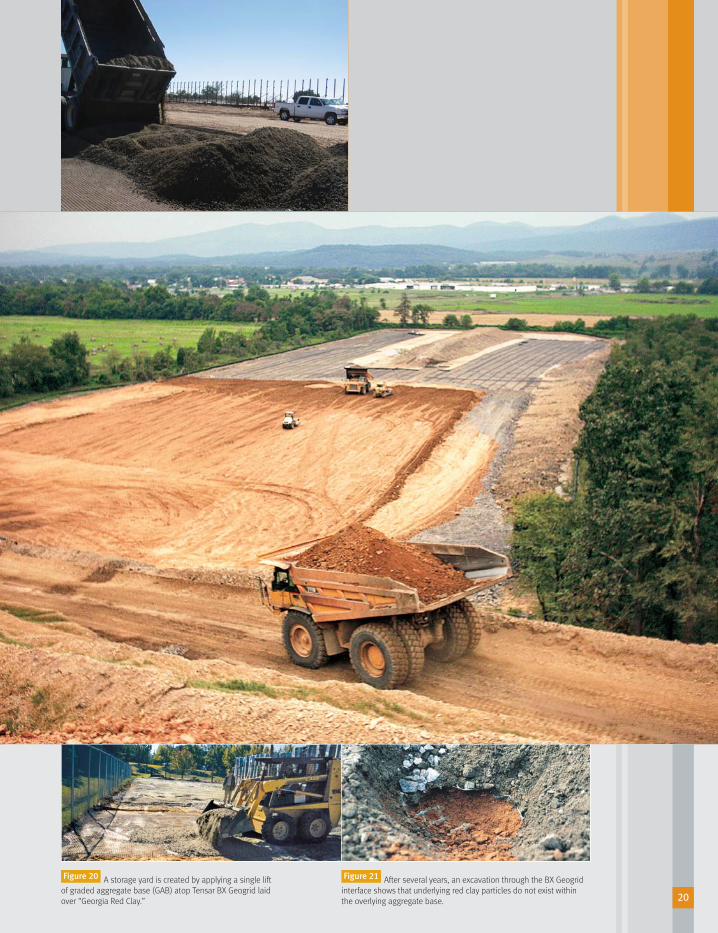
Mechanical Separation Case Study –Tensar’s Manufacturing Plant, Morrow, Georgia
The storage yard for Tensar’s manufacturing plant in
Morrow, Georgia, rests on “Georgia Red Clay” topped by
Tensar BX Geogrid and a standard, well-graded DOT-type
aggregate base. The hard standing area supports a high
volume of heavy lifting equipment that generates
significant subsurface pressures. Examination of several
test pits excavated at the site revealed that the aggregate
fill, after several years’ service, is continuing to function
as a “natural” filter and that the geogrid reinforcement
maintains a clear separation between the aggregate and
the underlying subsoil (Figures 20 and 21). An examination
of the grading curve data shown below for the aggregate
and underlying “Georgia Red Clay” illustrates why this
is the case (Figure 19).
D15 Filter
D85 Subgrade
D50 Filter
D50 Subgrade< 25
“Georgia Red Clay,” like
most naturally occurring subgrades,
is not 100% clay-sized. In many
instances, like this one, there are as
many sand-sized particles as clay-sized
particles. As such, a DOT-grade base
is a very effective filter, as evidenced
by the piping ratio calculation.
Subgrade PI > 7; there is therefore,
no need to check the Average Size
Ratio (D50f/D50s).
Piping Ratio= D15f/D85s= 0.22/0.62= 0.4 < 5 OK*
3 in.
85%
15%
% F
iner
by
Wei
ght
100
80
60
40
20
0
Gravel
Subgrade (Georgia Red Clay)Pl = ~20 – 25
D15 = 0.22mmD85 = 0.62mm
Aggregate Fill(Graded Aggregate Base)
#4 #200 Silt & Clay
Filter Analysis – Manufacturing Plant Site
Sand
100 10
Grain Size (mm)
1 0.1 0.01 0.001
Figure 19
*
Separation (continued) >
< 5
67797_SpectraBrochure_OP-Cindy6.0 9/24/08 2:31 PM Page 19
20
A storage yard is created by applying a single lift
of graded aggregate base (GAB) atop Tensar BX Geogrid laid
over “Georgia Red Clay.”
After several years, an excavation through the BX Geogrid
interface shows that underlying red clay particles do not exist within
the overlying aggregate base.
Figure 20 Figure 21
67797_SpectraBrochure_OP-Cindy6.0 9/24/08 2:31 PM Page 20

There is often confusion regarding the performance
of geogrids versus geotextiles in paved and unpaved
roadway applications. Geotextiles can provide separation
and filtration functions but are typically not as effective
as Tensar BX Geogrids when used for reinforcement
purposes alone.
In soil reinforcement applications, the strength and stiffness
of a geosynthetic is only significant if it can be transferred
efficiently into the surrounding soil. With Tensar BX Geogrids,
this is achieved by “mechanical interlock.” For geotextiles,
the load from the soil cannot be transferred in the same
manner; instead, the geosynthetic acts as a “tensioned
membrane” (Figure 22).
Some of the disadvantages of geotextiles in reinforced
roadway applications include:
• Their extreme flexibility can cause “kinks” even
after installation. As a result, the benefits of the
“membrane effect” are only realized after significant
deformation of the roadway, which is required
to build up tension within the geotextile. This
can cause premature distress to the structure
and require early maintenance.
• Longer embedments of geotextile can be required
to provide anchorage beyond the loaded area
of a roadway.
• Fixed wheel paths are required in order to ensure
the long-term performance of geotextile-reinforced
roadways. As geotextiles are generally not
pretensioned in the field during construction, rutting
of the subgrade needs to take place before heavy
traffic loads can be carried. It is essential that this
rutting is maintained and that additional ruts do
not form in adjacent areas along the subgrade-base
course interface.
• The formation of ruts in the subgrade, causes water
to accumulate. This results in the deterioration of
the roadway being accelerated.
As a result of the above disadvantages, the effective
use of geotextiles as roadway reinforcement is typically
restricted to narrow, unsurfaced haul roads.
Reinforcement Comparison with Geotextiles >
Geotextiles and geogrids perform differently.
When used for reinforcement,
Tensar BX Geogrids outperform
geotextiles. Tensar GeogridReinforcement Geotextile
Confinement versus membrane effect.
TensarGeogrid Geotextile
Confinement effect Tensioned membrane effect
Figure 22
67797_SpectraBrochure_OP-Cindy6.0 9/24/08 2:31 PM Page 21

Geogrid Testimony
In the early 1990s, the U.S. Army Corps of Engineers
conducted a full-scale pavement trial comparing the
performance of four geotextiles and a Tensar BX Geogrid to
an equivalent pavement section containing no geosynthetic
reinforcement. One of the geotextile sections performed
approximately the same as the control section while
the other three performed significantly worse
(Figures 23 and 24).
It is interesting to note that in the Corps’ test, the section
containing the strongest geotextile performed the worst
of all the test sections. It is believed that at the relatively
low strains encountered in roadway applications, there
is no reinforcing effect of the geotextile, and its smooth
surfaces may promote sliding of the aggregate. In this
particular example, it is likely that the strongest geotextile
promoted the most slippage of the aggregate.
The Tensar BX Geogrid test section performed well
compared to the control section in the Corps’ trial. Based
on this work and a review of more than 100 technical
papers and publications, the Corps concluded, “If
geotextiles are included in the structure, no structural
support should be attributed to the geotextiles.”
22
130 lbs
Control G2 G4 G5 G6 Tensar BXGeogrid
247 lbs
472 lbs 1,000 lbs
BX gridG6G5G4G2Control
Number of Passes
Pass
esfo
r 2
in.R
utRu
tdep
th (i
n.)
576 lbs/ft at5% strain
1000 2000 3000 4000 5000 60000
5t Military truck
G2, G4, G5 and G6geotextiles, value isgrab strength
6000
5000
4000
3000
2000
1000
0
0
1
2
3
4
ControlTensar BX GeogridG5
G2G4G6
Comparison of geotextiles and geogrids in
USACE trafficking trial.
Trial Section
This access road near Mobile, Alabama, was a contractor’s
nightmare. The unpaved road, built with fabrics, rapidly failed
as trucks were delivering fill to the site.
This is the same site with the same soil conditions. However, there’s
an important difference – this time the road was built with Tensar BX
Geogrids and it held up under repeated truck traffic.
Figure 23
Figure 24
67797_SpectraBrochure_OP-Cindy6.0 9/24/08 2:31 PM Page 22

Chemical stabilization using lime is a traditional solution
when soft or expansive clay subgrade soils are encountered.
While this method of subgrade stabilization has been used
successfully in the past, there are a number of important
factors to consider when selecting lime.
Performance Considerations
Versatility: Geogrids are effective for all types of soil.
Lime works best in heavy clays that are free of soluble
sulfates, which can create damaging heave after a
pavement is constructed. The chemical reaction, known
as sulfate-induced heave, can significantly affect the
smoothness of a finished pavement surface. Repair of
the pavement can be time consuming and costly.
Durability: In areas where frequent wet-dry or freeze-thaw
cycles are common, the long-term durability of lime
stabilized subgrades can be significantly affected by the
solubility of lime. Geogrids are unaffected by freeze-thaw
cycling and bridge seasonally soft soils by stiffening the
base. Lime modified soils can lose strength over time,
particularly in climates with frequent wet-dry cycles. These
actions lead to cracking and in some cases, premature
failure of the pavement.
Drainage: The drainage characteristics of a pavement
are key to its long-term performance. Lime stabilization
does nothing to improve the drainage capacity of a
road founded on weak, impermeable soil. In fact, the
technique can make a poor situation even worse.
A geogrid-reinforced granular base or sub-base layer
promotes “positive drainage” of the road, leading
to enhanced long-term performance.
Strength: Geogrids increase the effective bearing capacity
of subgrade soils. Lime improves strength only within the
treated depth, and its strengthening effects can deteriorate
with time based upon a variety of factors. Due to the
confinement of the overlying aggregate fill, geogrid
reinforcement immobilizes the potential horizontal and
vertical movement of aggregate due to applied construction
and in-service pavement loading. This increase in the
aggregate base stiffness improves the bearing capacity of
the subgrade without having to chemically or mechanically
modify the subgrade soil itself.
Comparison with Lime Stabilization >
With Tensar BX Geogrids,
there’s no need for specialized
labor and equipment.
67797_SpectraBrochure_OP-Cindy6.0 9/24/08 2:32 PM Page 23

Uniform Installation: Geogrids provide uniform
strength and performance in areas where they are
installed. Lime-treated areas may be highly variable
with respect to the rate of application, depth of treatment,
uniformity of mixture into the soil, and soil type
consistency. Lime installation is highly dependent
on the contractor’s expertise.
Design Considerations
Simplicity: In order to have full confidence in a soft
ground solution incorporating lime stabilization, the
designer requires complete knowledge of the soil type,
strength and plasticity for all subsoil materials likely to
be encountered. In practice, this data is rarely available
for the entire area being treated; and when it is, there
is no accurate account of material variation across the
job site. A geogrid solution is engineered through
traditional bearing capacity analysis and requires an
indication of subgrade strength alone. This information
is generally freely available to the designer, and variation
in subgrade strength across the site can be easily and
inexpensively identified.
Efficiency: Tensar BX Geogrids are manufactured under
controlled conditions and provide a uniform product with
well-known design characteristics that are not subject to
field variability. Lime must be mixed on site under much
less controlled conditions; in practice additional lime is
typically specified to account for field variability, adding
unnecessary cost to the project.
Safety/Environmental: Geogrids do not require special
environmental controls. Lime stabilization requires
personal safety standards and environmental controls.
With lime, leaching is often a problem in the presence of
moisture flow and therefore this technique is inappropriate
in environmentally sensitive areas such as wetlands. The
high alkalinity of lime-treated soils can affect vegetation
adjacent to the area being treated. Precautions should
be taken prior to installation where vegetation must
be kept intact.
24
Soils containing soluble sulfates are not good candidates for lime
treatment. Note: The calcium in lime reacts to form ettrignite and the
resulting reaction can cause significant damage to pavement structures.
Even when using proper specialized equipment and experienced
contractors, construction with lime is highly dependent upon favorable
weather conditions.
67797_SpectraBrochure_OP-Cindy6.0 9/24/08 2:32 PM Page 24

Effective in all types of soils and
unaffected by weather conditions,
BX Geogrids can be installed quickly
and easily while keeping the project
on schedule.
Installation Considerations
General Access: Lime equipment may be difficult or even
impossible to operate over very soft soils. However, the
“snowshoe” effect provided by BX Geogrids allows
conventional construction equipment to operate over
these soils. Field research performed by the U.S. Army
Corps of Engineers revealed that Tensar BX Geogrids
enable equipment to be mobilized over extremely weak
subgrades (CBR = 0.4).
Uniformity: Geogrids are uniform products that install
easily and predictably. Lime must be skillfully mixed,
placed and compacted for optimum performance.
Non-uniformity of subgrade soils chemically modified
or stabilized with lime will affect the consistency of the
subgrade support.
Stability: Geogrids are suitable for installation in the
coldest and most inclement weather. Lime requires
dry conditions with little or no wind and temperatures
in excess of 40°F. It is also a requirement that the
moisture content of the subgrade soil be maintained
close to optimum.
Speed: Locally available geogrids install quickly over
problem soils. Lime stabilization requires mixing, curing
(mellowing) and compaction, which can take several
days even in optimum weather conditions. Geogrids
offer construction expediency over lime treatment,
because they provide mechanical rather than
chemical solution.
Uncomplicated: Tensar BX Geogrids do not require
a significant investment in equipment and labor to ensure
a quality installation, as is the case with lime stabilization.
Conventional labor and equipment may be utilized to
install the lightweight rolls of geogrid and aggregate.
Comparison with Lime Stabilization (continued) >
The dangerous environmental effects of lime to the air are often obvious.Lime stabilization requires mixing, curing and compaction, which can take
several days even in optimum weather conditions.
67797_SpectraBrochure_OP-Cindy6.0 9/24/08 2:32 PM Page 25

26
67797_SpectraBrochure_OP-Cindy6.0 9/24/08 2:32 PM Page 26

SpectraPave3™ Software
Tensar International Corporation breaks new ground
with the release of our industry-leading SpectraPave3™
Software. This new software allows the user to accurately
predict the performance of geogrid reinforced and
unreinforced conditions of both paved and unpaved
surfaces. The software offers three distinct analyses
modules (Figure 25) and cost analyses tools to evaluate
design options for paved roads, unpaved roads and
working surfaces which include:
• Subgrade Improvement
• Base Course Reinforcement – Standard Method
• Base Course Reinforcement – Advanced Method
Subgrade ImprovementDeveloped in accordance with the latest Giroud-Han
design methodology, this module allows the designer
to consider the cost benefits of using BX Geogrids
in unreinforced aggregate sections. Similar sections
containing geotextiles or other geogrid materials
can also be analyzed. The program output includes
a breakdown of aggregate savings, undercut savings
and overall project savings.
Base Reinforcement
This module was developed to allow the designer to
consider the benefits of using BX Geogrids in paved
roadway applications generally subjected to heavy
traffic over long periods of time. The calculations
undertaken are in full accordance with AASHTO’s
(1993) Flexible Pavement Design Guide and
Provisional Standard PP 46-01 (Figure 26).
Cost Analysis Tools
What’s more economical: a road reinforced with
BX Geogrids or a conventional section? The cost analysis
tools provide total in-place costs (and savings) for each
design option in dollars per unit area. This flexibility also
enables you to quickly predict performance and value
Design Tools >
Users have the option to navigate to three unique analysis
modules as well as a project information folder from the home page
of SpectraPave3 Software.
Both base reinforcement modules allow designers to
analyze an unreinforced and geogrid reinforced condition to realize
component reduction and/or extended pavement service life in a
flexible pavement section.
Figure 25 Figure 26
By using SpectraPave3™ Software
or the Subgrade Improvement Slide
Rule, cost savings can be calculated
quickly and easily.
67797_SpectraBrochure_OP-Cindy6.0 9/24/08 2:32 PM Page 27

28
engineer comparisons for a range of design scenarios
for the life of the pavement through the life-cycle cost
analysis tool found in the Advanced Method.
SpectraPave3 Software is available in CD-ROM format
supporting Windows 95, 98, 2000, XP and NT operating
systems. It may also be downloaded free of charge from
www.tensar-international.com. For more information or to
request your free copy, call 800-TENSAR-1 or contact your
local Tensar BX Geogrid distributor.
Subgrade Improvement Slide Rule
This handy, pocket-sized tool uses the same
state-of-the-art Giroud-Han Design Methodology
used in SpectraPave3 Software and also contains
a cost calculator to determine the financial advantages
of using BX Geogrids to reduce the required aggregate
thickness. The slide rule is primarily intended for use on
earthwork sites where quick decisions need to be made
concerning the use of geogrid reinforcement in subgrade
improvement applications. If the user knows the typical
prices for the supply of aggregate and the excavation and
disposal of any undercut material, a few simple steps can
be taken to reveal the economic advantages of using the
Spectra System (Figure 27).
The slide rule output is based on the SpectraPave3 Software Subgrade
Improvement module, which uses the state-of-the-art Giroud-Han Design Methodology.
The slide rule brings this advanced technology right to where it is needed most – the
project site.
Figure 27
The slide rule is available in three versions: English units,
metric units and translated into Spanish with metric units.
This easy-to-use tool will eliminate the uncomfortable
guesswork often associated with soft soils, and allows
the user to recommend economical solutions quickly
and with confidence. To order a Subgrade Improvement
Slide Rule, call 800-TENSAR-1 or contact your local
Tensar BX Geogrid distributor.
67797_SpectraBrochure_OP-Cindy6.0 9/24/08 2:32 PM Page 28

Installati0n >
Recommended Overlaps
SOIL DESCRIPTION CBR OVERLAP
Firm ≥ 4 1 ft
Soft Ground 2-4 1-2 ft
Very Soft Ground 0.5-2 2-3 ft
Extremely Soft Ground ≤ 0.5 3 ft
Figure 28
Site Preparation
Tensar BX Geogrids are quick and easy to install. A smooth
graded surface is ideal for placement of Tensar BX
Geogrids. Tree stumps, boulders and other protruding
objects should be removed or cut at ground level.
Conventional practices may be used (clearing and
grabbing, topsoil removal and compaction) to properly
prepare a subgrade prior to placement of the geogrid.
Unique measures should be considered for extremely
soft subgrades (CBR < 1.0) to minimize disturbance
of the site soils.
Placement of Geogrids
After preparing the site, the geogrids are rolled out over
the subgrade. A 1- to 3-ft overlap (shingle style, in the
direction of fill advancement) is sufficient to ensure
stability across the installation. The actual overlap length
and any anchoring pattern required is dependent on the
subgrade strength. The weaker the subgrade, the greater
the overlap length required (Figure 28).
Placement of Fill
The required fill thickness is dependent upon the subgrade
strength, quality of fill used and the expected amount of
traffic. This can be quantified by using the SpectraPave3
Software or the Subgrade Improvement Slide Rule. In
order to minimize potential damage to the geogrid during
compaction, the initial lift should be at least 6 in., but under
no circumstances less than 4 in. The initial lift thickness
used should be based on the subgrade strength and the
loadings imposed by the placement and compaction
machinery. In very soft soil conditions, it is prudent to dump
fill on stable ground and then push it out over the geogrid.
The dozer blade should be “feathered”upward and raised
as each lift is pushed out at the leading edge of fill
advancement. After the geogrid and overlying fill have been
placed, normal compaction methods may be used.
Utility Concerns
Utility trenches often need to be excavated after geogrids
and fill material have been placed. This raises the concern
that the geogrid’s ability to provide reinforcement in these
areas will be compromised. The solution is a simple repair
process that overlaps the geogrids as the service trench
is backfilled. Detailed installation requirements for
Tensar BX Geogrids are provided in the Spectra System
Installation Guide.
Tensar BX Geogrids can be used for projects involving utility trenches.
67797_SpectraBrochure_OP-Cindy6.0 9/24/08 2:32 PM Page 29

The Solution That Works Every Time >
The Spectra System Advantage
For more than 20 years, industry professionals have
been using structural geogrids from Tensar International
Corporation to reinforce unstable subgrades. With clear
advantages in performance, design and installation,
mechanical stabilization with Tensar BX Geogrids
provides a preferred technology for building economical,
long-lasting structures over challenging soils.
Our entire worldwide distribution team is dedicated to
providing the highest-quality products, service and
support. With a technically trained sales staff and an
in-house engineering department, Tensar International
Corporation keeps its systems at the forefront of today’s
design technology and market trends.
For more information on the Spectra Roadway
Improvement System please call 800-TENSAR-1, visit
www.tensar-international.com or e-mail [email protected].
We are happy to supply you with additional BX Geogrid
information, complete installation guidelines, system
specifications, design details, conceptual designs,
preliminary cost estimates, case studies, software
and much more.
For information on how Tensar BX Geogrids can be
used in rail applications, see our Spectra Rail System
overview brochure.
30
REFERENCES:
1 Webster, S.L. 1992. Geogrid Reinforced Base Course for Flexible Pavementsfor Light Aircraft: Test Section Construction, Laboratory Tests and DesignCriteria. U.S. Army Corps of Engineers Report No. DOT/FAA/RD-92-25. UnitedStates Army Corps of Engineers, Washington, D.C.
2 Huntington, George & Ksaibati, Khaled. 1999. Evaluation of Geogrid-Reinforced Granular Base, Proceedings: Recent Advances in theCharacterization of Geo-Materials, (June 13–17), University of Illinois –Champagne.
3 Al-Qadi, Tutumluer, Kwon, Dessouky. 2007. Accelerated Full-Scale Testing of Geogrid-Reinforced Flexible Pavements, Proceedings: TransportationResearch Board 86th Annual Meeting, (January 21–25), Washington, D.C.
4 Perkins, S.W. 1999. Geosynthetic Reinforcement of Flexible Pavements: Laboratory Based Pavement Test Sections. Final Report, FHWA/MT-99-001/8138. United States Department of Transportation, Federal HighwayAdministration, Washington, D.C.
5 Giroud, J.P. & Han, Jie. 2004. Design Method for Geogrid-Reinforced Unpaved Roads. I. Development of Design Method, American Society of Civil Engineers
Journal of Geotechnical and Geoenvironmental Engineering, (August); Volume 130, Number 8.
6 Department of the Army, U.S. Army Corps of Engineers. 2003. Use of Geogrids in Pavement Construction, Engineering Technical Letter 1110-1-189.
7 AASHTO. 1993. AASHTO Guide for Design of Pavement Structures. American Association of State Highway and Transportation Officials, Washington, D.C.
8 AASHTO. 2003. Recommended Practice for Geosynthetic Reinforcement ofthe Aggregate Base Course of Flexible Pavement Structures. AASHTOPublication PP46-01. American Association of State Highway andTransportation Officials, Washington, D.C.
9 Kentucky Transportation Cabinet. 2004. Design Procedures for Roadbed Stabilization with Geogrids. Design Memorandum No. 17-04.
10 Cedergen, Harry R. 1989. See page, Drainage, and Flow Nets, Third Edition. John Wiley & Sons, New York, pgs. 153-156.
11 White, D.W. 1990. Literature Review of Geotextiles to Improve Pavements forGeneral Aviation Airports. U.S. Army Corps of Engineers Report No.DOT/FAA/RD-90/26. United States Army Corps of Engineers, Washington, D.C.
67797_SpectraBrochure_OP-Cindy6.0 9/24/08 2:32 PM Page 30

©2008, Tensar International Corporation. Certain products and/or applications described or illustrated herein are protectedunder one or more U.S. patents. Other U.S. patents are pending, and certain foreign patents and patent applications mayalso exist. Trademark rights also apply as indicated herein. Final determination of the suitability of any information ormaterial for the use contemplated, and its manner of use, is the sole responsibility of the user. Printed in the U.S.A.
Distributed by:
SPECTRA_BRO_7.08
Tensar International Corporation
5883 Glenridge Drive, Suite 200
Atlanta, Georgia 30328
800-TENSAR-1
www.tensar-international.com
67797_SpectraBrochure_OP-Cindy6.0 9/24/08 2:30 PM Page 1