Embed Size (px)
Citation preview

THE R8184M PROTECTORELAY OIL BURNER CON- TROLOPERATES THE OIL BURNER AND OIL VALVE (IF DESIRED) IN RESPONSE TO A CALL FOR HEAT FROM A LOW VOLTAGE CONTROL CIRCUIT.
0 Provides intermittent ignition.
0 Used with a C564A Cadmium Sulfide Cell and 24 Vat thermostat.
Cl Integral 24 Vat transformer powers bw voltage con- trol circuit.
q Solid state flame sensing circuit.
Cl Enclosed safety switch with external red reset button. Safety switch must be manually reset after safety shut- down.
0 45 second safety switch timing.
0 Exposed terminal strip with screw terminals for low voltage connections. Y and G terminals are tie points for cooling circuit connections.
0 Color-coded leadwires for line voltage connections.
0 Mounts in any position on a standard 4 x 4 inch junction box or directly on burner housing.
Honeywell
D.T. 11-90
Form Number 68-0111 @Honeywell Inc. 1990
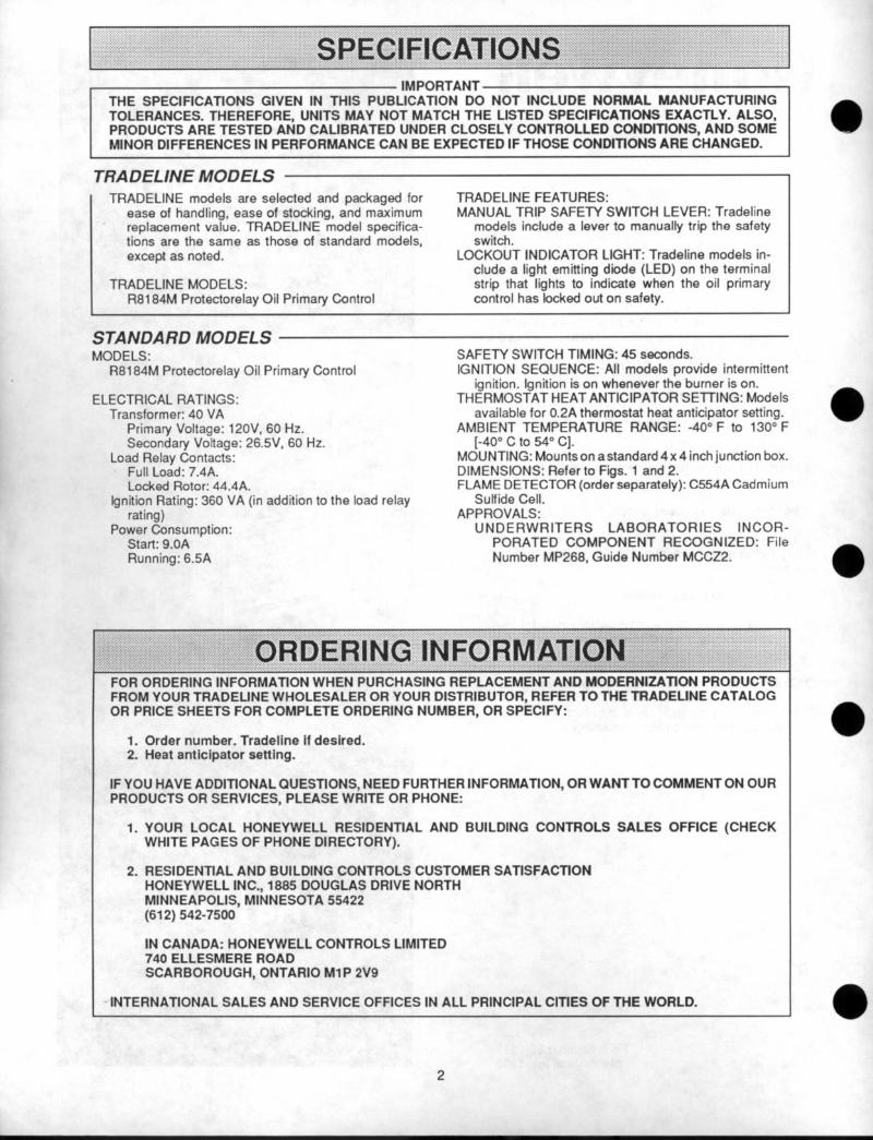
IMPORTANT THE SPEClFlCATlONS GIVEN IN THIS PUBLICATION DO NOT INCLUDE NORMAL MANUFACTURING TOLERANCES. THEREFORE, UNITS MAY NOT MATCH THE LISTED SPECIFICATIONS EXACTLY. ALSO, PRODUCTS ARE TESTED AND CALIBRATED UNDER CLOSELY CONTROLLED CONDITIONS, AND SOME MINOR DIFFERENCES IN PERFORMANCE CAN BE EXPECTED IF THOSE CONDITIONS ARE CHANGED.
TRADELINE MODELS TRADELINE models are selected and packaged for
ease of handling, ease of stocking, and maximum replacement value. TRADELINE model specifica- tions are the same as those of standard models, except as noted.
TRADELINE MODELS: R8184M Protectorelay Oil Primary Control
TRADELINE FEATURES: MANUAL TRIP SAFETY SWITCH LEVER: Tradeline
models include a lever to manually trip the safety switch.
LOCKOUT INDICATOR LIGHT: Tradeline models in- clude a light emitting diode (LED) on the terminal strip that lights to indicate when the oil primary control has locked out on safety.
STANDARD MODELS MODELS:
R8184M Protectorelay Oil Primary Control
ELECTRICAL RATINGS: Transformer: 40 VA
Primary Voltage: 12OV, 60 Hz. Secondary Voltage: 26.5V, 60 Hz.
Load Relay Contacts: Full Load: 7.4A. Locked Rotor: 44.4A.
Ignition Rating: 360 VA (in addition to the load relay rating)
Power Consumption: Start: 9.OA Running: 6.5A
SAFETY SWITCH TIMING: 45 seconds. IGNITION SEQUENCE: All models provide intermittent
ignition. Ignition is on whenever the burner is on. THERMOSTAT HEAT ANTICIPATOR SETTING: Models
available for 0.2A thermostat heat anticipator setting. AMBIENT TEMPERATURE RANGE: -40” F to 130” F
[-40” c to 54” C]. MOUNTING: Mounts on a standard 4 x 4 inch junction box. DIMENSIONS: Refer to Figs. 1 and 2. FLAME DETECTOR (order separately): C554A Cadmium
Sulfide Cell. APPROVALS:
UNDERWRITERS LABORATORIES INCOR- PORATED COMPONENT RECOGNIZED: File Number MP268, Guide Number MCCZ2.
:. .:.. . . . . .::. i~:~:::-:aw’BERi’~~:~iNF~~~~~~~~~~:I_rI~~~~~~~ . . ...:
FOR ORDERING INFORMATION WHEN PURCHASING REPLACEMENT AND MODERNIZATION PRODUCTS FROM YOUR TRADELINE WHOLESALER OR YOUR DISTRIBUTOR, REFER TO THE TRADELINE CATALOG OR PRICE SHEETS FOR COMPLETE ORDERING NUMBER, OR SPECIFY:
1. Order number. Tradellne If desired. 2. Heat anticipator setting.
IF YOU HAVE ADDlTlONAL QUESTIONS, NEED FURTHER INFORMATION, OR WANTTO COMMENT ON OUR PRODUCTS OR SERVICES, PLEASE WRITE OR PHONE:
1. YOUR LOCAL HONEYWELL RESIDENTIAL AND BUILDING CONTROLS SALES OFFICE (CHECK WHITE PAGES OF PHONE DIRECTORY).
2. RESlDENTlAL AND BUILDING CONTROLS CUSTOMER SATlSFACTlON HONEYWELL INC., 1885 DOUGLAS DRIVE NORTH MINNEAPOLIS, MINNESOTA 55422 (612) 542-7500
IN CANADA: HONEYWELL CONTROLS LIMITED 740 ELLESMERE ROAD SCARBOROUGH, ONTARIO MlP 2V9
INTERNATlONAL SALES AND SERVICE OFFICES IN ALL PRINCIPAL ClTlES OF THE WORLD.
2

W.mTOREsET
1 4iE 11031
FIG. l-R8184M MOUNTING DIMENSIONS IN INCHES AND [MILLIMETERS].
POWER LEAD
FIG. 2-R8184M MOUNTING PLATE IN INCHES AND [MILLIMETERS].
3 68-0111
WHEN INSTALLING THIS PRODUCT... 1. Read these instructions carefully. Failure to follow
them could damage the product or cause a hazardous condition.
2. Check the ratings given in these instructions and on the product to ensure the product is suitable for your application.
3. Ensure the installer is a trained, experienced service technician.
4. After completing installation, use these instructions 3. Mount the R8184M to the junction box. Refer to to check product operation. Fig. 4.
CHOOSE LOCATlON
MAKE WlRlNG CONNECTlONS AND MOUNT R8184M
1. Ensure all wiring complies with local codes and ordinances.
2. Make line voltage connections as shown in Fig. 3. l Splice leads with solderless connectors. l Do not exceed load ratings shown on device label or
in the Specifications, page 2. l Leave enough slack in the wires to permit easy
access into the junction box.
4. Connect the C554A Cadmium Sulfide Cell (ordered seoaratelv) leadwires to the F-F terminals on the terminal
‘.’ :. ..‘.’ ‘. rNsTALt*T,ON::‘ ..‘..:; ‘,..‘:‘.‘~,~..‘.“;..’ :
l Mount the R8184M on a 4 x 4 inch junction box, strip, - ’ directlyontheburnerhousing,orinsidetheappliance cabinet. 5. Connect all remaining lowvoftage wiring connections
l In replacement applications, mount the R8184M in as shown in Fig. 3. the same location as the old control.
9 Make all line voltage connections in a wiring enclo- sure such as a junction box or the appliance wiring NOTE: Y and G terminals are provided to simplify cpnnec- compartment. tions of cooling equipment; they are not connected to
l Ensure operating temperatures at the selected loca- the internal circuitry of the R8184M. tion are between -40°F and 130°F [-4O”C and 54%].
THERMOSTAT
WIMI
R8104M PROTECTORELAY
CONTROL I
Ir
-CAPACITOR
I BLACK
L I
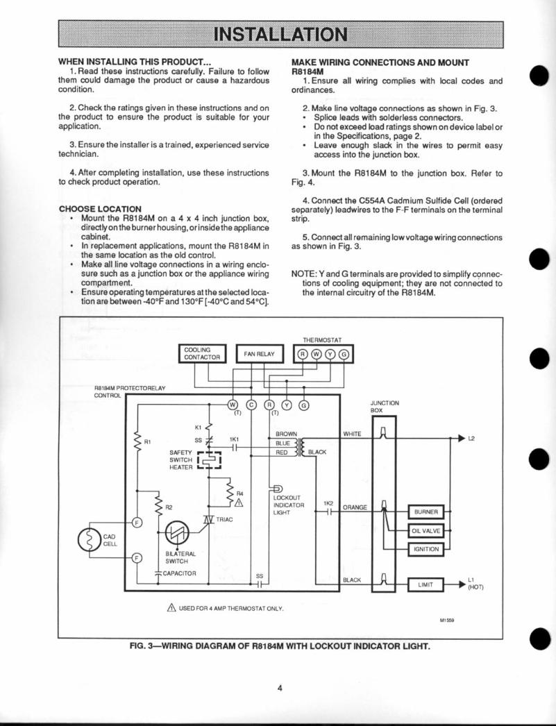
A USED FOR 4 AMP THERMOSTAT ONLY.
Ll
(HOT)
FIG. 3--WIRING DIAGRAM OF R8184M WlTH LOCKOUT INDICATOR LIGHT.
4
i
THERMOSTAT
JUNCTION
Ll
(HOT)
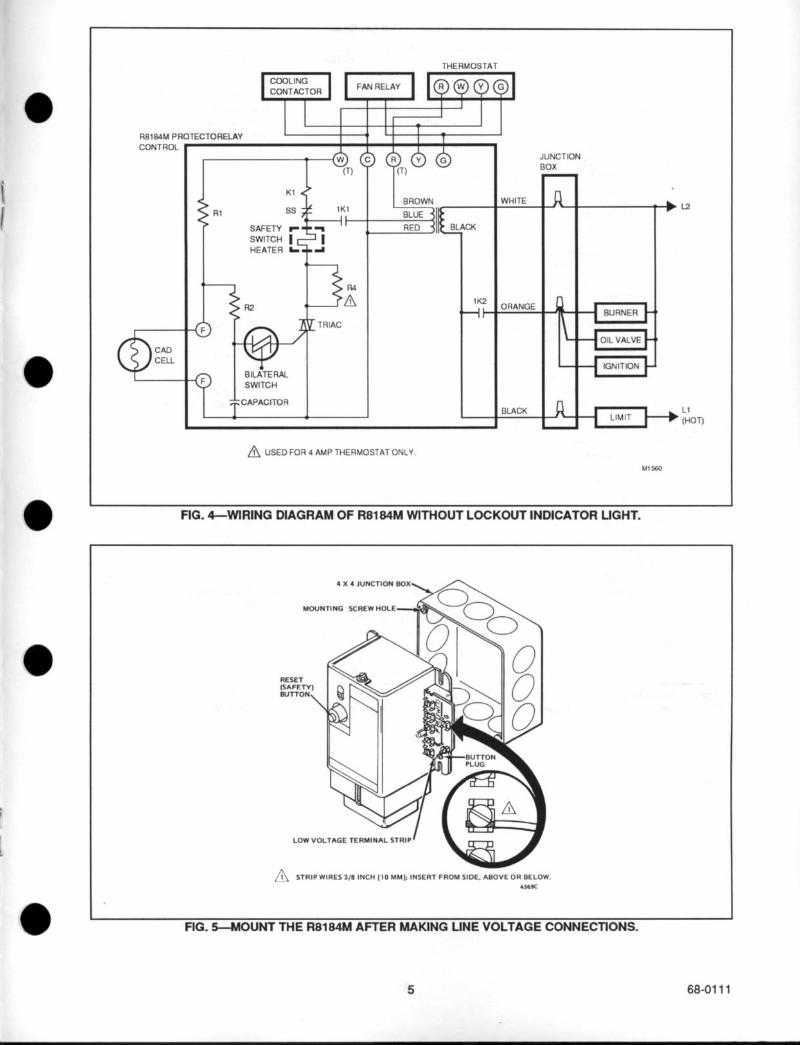
&, USED FOR 4 AMP THERMOSTAT ONLY.
FIG. 4-WIRING DIAGRAM OF R8184M WITHOUT LOCKOUT INDICATOR LIGHT.
4 X 4 JUNCTION BOX
MOUNTING SCREW HOLE
LOW VOLTAGE TER
FIG. 5-MOUNT THE R8184M AFTER MAKING LINE VOLTAGE CONNECTIONS.
5 68-0111
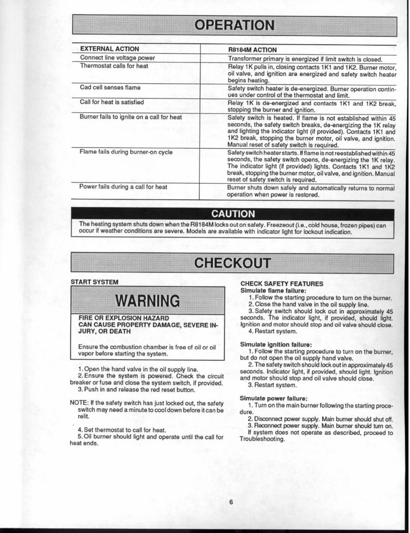
EXTERNAL ACTION
Connect line voltage power
Thermostat calls for heat
Cad cell senses flame
Call for heat is satisfied
Burner fails to ignite on a call for heat
Flame fails during burner-n cycle
Power fails during a call for heat
R8184M ACTION
Transformer primary is energized if limit switch is closed.
Relay 1 K pulls in, closing contacts 1 Kl and 1 K2. Burner motor, oil valve, and ignition are energized and safety switch heater begins heating.
Safety switch heater is de-energized. Burner operation contin- ues under control of the thermostat and limit.
Relay 1 K is de-energized and contacts 1 Kl and 1 K2 break, stopping the burner and ignition.
Safety switch is heated. If flame is not established within 45 seconds, the safety switch breaks, de-energizing the 1 K relay and lighting the indicator light (if provided). Contacts 1Kl and lK2 break, stopping the burner motor, oil valve, and ignition. Manual reset of safety switch is required.
Safety switch heater starts. tf flame is not reestablished within 45 seconds, the safety switch opens, de-energizing the 1K relay. The indicator light (if provided) lights. Contacts 1Kl and lK2 break, stopping the burner motor, oil valve, and ignition. Manual reset of safety switch is required.
Burner shuts down safely and automatically returns to normal operation when cower is restored.
The heating system shuts down when the R8184M locks out on safety. Freezeout (i.e., cbld house, frozen pipes) can occur if weather conditions are severe. Models are available with indicator light for lockout indication.
: ‘.cHECKo”T.
iTART SYSTEM . . . . . . . . . :::: ,.,...... :: . . . . . . . . . . . ..‘. . . . . . . . . .
~~~~~~~~~~~~
..’ : : :.,.: :,, j :
FIRE OR EXPLOSION HAZARD CAN CAUSE PROPERTY DAMAGE, SEVERE IN- JURY, OR DEATH
Ensure the combustion chamber is free of oil or oil vapor before starting the system.
1. Open the hand valve in the oil supply line. 2.Ensure the system is powered. Check the circuit
breaker or fuse and close the system switch, if provided. 3. Push in and release the red reset button.
NOTE: If the safety switch has just locked out, the safety switch may need a minute to cool down before it can be relit.
4. Set thermostat to call for heat. 5.Oil burner should light and operate until the call for
heat ends.
CHECK SAFETY FEATURES Simulate flame failure:
1. Follow the starting procedure to turn on the burner. 2. Close the hand valve in the oil supply line. 3.Safety switch should lock out in approximately 45
seconds. The indicator light, if provided, should light. Ignition and motor should stop and oil valve should close.
4. Restart system.
Simulate ignttlon fallure: 1. Follow the starting procedure to turn on the burner,
but do not open the oil supply hand valve. 2. The safety switch should lock out in approximately45
seconds. Indicator light, if provided, should light. Ignition and motor should stop and oil valve should close.
3. Restart system.
Simulate power failure: 1. Turn on the main burner following the starting proce-
dure. 2. Disconnect power supply. Main burner should shut off. 3. Reconnect power supply. Main burner should turn on. lf system does not operate as described, proceed to
Troubleshooting.
6

control if ooeration is not as described.
To completely troubleshoot an oil burner installation, check the burner, ignition transformer, oil primary control, and cad cell for proper operation and condition.
CHECK CAD CELL AND R8184M .\.. . . . . . . . . . . . . . . . .::: ::. ::, .;::. . . . . . . . . .
,.,.. ..,........................................../. . . . :.:.::.:.:.:.:.:.:.::...:.... ., ..::..:::.:.:.:.:.::.:.::
‘!~~~~W~~~~~ ,.:.: . . . . . . . .:.:*:.... .:.
.:.:.:.: . .,..:..,:: :.j:..: . . . . . . . . . . . .:: :.. ., . . . ::‘,:‘::.‘., ,,““““’ “” :: ‘:
FIRE OR EXPLOSION HAZARD CAN CAUSE PROPERTY DAMAGE, SEVERE IN- JURY, OR DEATH Troubleshootingisdonewiththeequipmentpowered. Observe all necessary precautions to prevent elec- trical shock or equipment damage.
Usethefollowing equipmenttotroubleshoottheR8184M and cad cell.
l Screwdriver l 0 to 150 Vat voltmeter l Insulated jumper wire with both ends stripped l Ohmmeter l 2700 Ohm resistor (optional)
Burner Motor Does Not Start When Thermostat Calls For Heat PRELIMINARY CHECKS
1. Make sure limit switch is closed and that contacts are clean.
2. Check for line voltage power at the oil primary. With thermostat calling for heat, voltage between black and white leadwires on oil primary should be 120 Vat.
CORRECTIVE AC
BURNER STARTS
Trouble is in thermostat circuit. Check thermostat and wiring connections.
Cad cell is seeing external light, is defective, or cad cell connections are shorted. Go to step 3.
Eliminate external light source or permanently shield cad cell.
ION
BURNER DOESN’T START
Trouble is in cad cell or oil primary. Go to step 2.
Disconnect power; check all wiring connections. Tighten any loose connections, if necessary, and retest. If burner motor and ignition still don’t start, replace oil primary. lf ignition is on and burner motor is off, check burner motor and wiring connections to motor. Replace burner motor, if necessary.
Replace cad cell with Part No. 130367.
Burner Motor Starts But Flame Is Not Established Check burner and ignition transformer per manufacturer’s recommendations. This is not an oil primary or cad cell problem.
7 68-0111
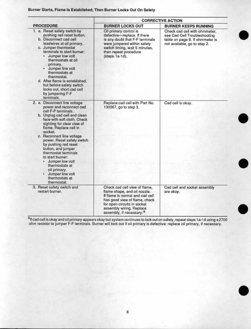
Burner Starts, Flame Is Established; Then Burner Locks Out On Safety
PROCEDURE 1. a. Reset safety switch by
pushing red reset button. b. Disconnect cad cell
leadwires at oil primary. c. Jumper thermostat
terminals to start burner: l Jumper low volt
thermostats at oil primary.
l Jumper line volt thermostats at thermostat.
d. After flame is established, but before safety switch locks out, short cad cell by jumpering F-F terminals.
2. a.
b.
C.
Disconnect line voltage power and reconnect cad cell F-F terminals. Unplug cad cell and clean face with soft cloth. Check sighting for clear view of flame. Replace cell in socket. Reconnect line voltage power. Reset safety switch by pushing red reset button, and jumper thermostat terminals to start burner: l Jumper low volt
thermostats at oil primary.
l Jumper line volt thermostats at thermostat.
3. Reset safety switch and restart burner.
T CORRECTIVE ACTION
BURNER LOCKS OUT Oil primary control is defective-replace. If there is any doubt that F-F terminals were jumpered within safety switch timing, wait 5 minutes, then repeat procedure (steps 1 a-l d).
Replace cad cell with Part No. 130367, go to step 3.
Check cad cell view of flame, flame shape, and oil nozzle. If flame is normal and cad cell has good view of flame, check for open circuits in socket assembly wiring. Replace assembly, if necessary.a
BURNER KEEPS RUNNING Check cad cell with ohmmeter, see Cad Cell Troubleshooting table on page 9. If ohmmeter is not available, go to step 2.
Cad cell is okay.
Cad cell and socket assembly are okay.
“If cad cell is okay and oil primary appears okay but system continues to lockout on safety, repeat steps 1 a-l d using a2700 ohm resistor to jumper F-F terminals. Burner will lock out if oil primary is defective; replace oil primary, if necessary.
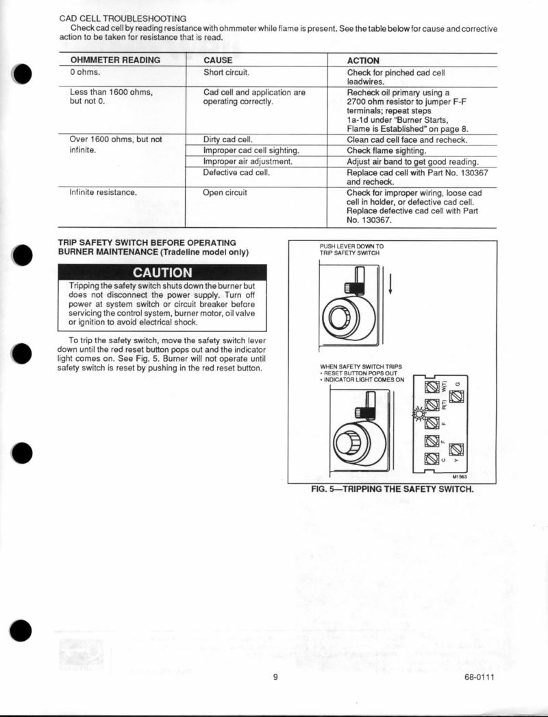
CAD CELL TROUBLESHOOTING Checkcad cell by reading resistance with ohmmeter while flame is present. See the table belowforcause and corrective
action to be taken for resistance that is read.
OHMMETER READING CAUSE I ACTION
Short circuit.
Cad cell and application are operating correctly.
I Check for oinched cad cell leadwires.’
Recheck oil primary using a 2700 ohm resistor to jumper F-F
I terminals; repeat steps 1 a-ld under “Burner Starts.
Over 1600 ohms, but not
infinite.
Infinite resistance.
Dirty cad cell.
Improper cad cell sighting.
Improper air adjustment.
Defective cad cell.
Open circuit
Flame is Established” on page 8.
Clean cad cell face and recheck.
Check flame sighting.
Adjust air band to get good reading.
Replace cad cell with Part No. 130367 and recheck.
Check for improper wiring, loose cad cell in holder, or defective cad cell. Replace defective cad cell with Part No. 130367.
TRIP SAFETY SWITCH BEFORE OPERATING BURNER MAINTENANCE (Tradeline model only)
TrIppIng the safety switch shutsdown the burner but does not disconnect the power supply. Turn off power at system switch or circuit breaker before servicing the control system, burner motor, oil valve or ignition to avoid electrical shock.
To trip the safety switch, move the safety switch lever down until the red reset button pops out and the indicator light comes on. See Fig. 5. Burner will not operate until safety switch is reset by pushing in the red reset button.
PUSH LEVER DOWN TO TRIP SAFElY SWITCH
WHEN SAFETY SWITCH TRIPS - RESET BUTTON FOPS OUT . INDICATOR LIGHT COMES ON
FIG. 5-TRIPPING THE SAFETY SWITCH.
e 9 68-0111