Embed Size (px)
Citation preview

PRODUCT DATA
® U.S. Registered TrademarkCopyright © 1997 Honeywell Inc. • All Rights Reserved 68-0184
R8889A,B,C,D Hydronic Zone ValvePanels with Priority Control
APPLICATIONThe R8889A,B,C,D Hydronic Zone Valve Panels with PriorityControl provide relay switching for multizone hot water controlsystems.
FEATURES• Provide burner control and zone valve control for up
to three (R8889A,C) or four (R8889B,D) zones in hotwater systems.
• Zone 1 may be selected to give priority to the indirecthot water tank.
• Panels may be wired together for expansion whilemaintaining priority zoning.
• Up to four panels (12 to16 zones total) may be used ina system.
• R8889 may be used in combination with R8888Hydronic Circulator Zone Panels with Priority Control.
• For use in residential and light commercial applications.• Include replaceable 24V transformer to provide power
for low voltage control circuit and valve loads.• Include diagnostic light-emitting diodes (LEDs) for
troubleshooting.• All models include burner relays, which are socket-
mounted and field-replaceable. Select models includezone relays that are field-replaceable.
• Clearly marked terminal designations provide easy wiring.• Compatible with electronic and electromechanical
thermostats and Honeywell Aquastat® Controls.• Mount horizontally only.
Contents
Application......................................................................... 1Features ............................................................................ 1Specifications .................................................................... 2Ordering Information ......................................................... 2Installation ......................................................................... 4Operation .......................................................................... 15Service and Checkout ....................................................... 15Troubleshooting ................................................................. 16

R8889A,B,C,D HYDRONIC ZONE VALVE PANELS WITH PRIORITY CONTROL
68-0184 2
ORDERING INFORMATIONWhen purchasing replacement and modernization products from your TRADELINE® wholesaler or distributor, refer to theTRADELINE® Catalog or price sheets for complete ordering number.
If you have additional questions, need further information, or would like to comment on our products or services, please write or phone:1. Your local Home and Building Control Sales Office (check white pages of your phone directory).2. Home and Building Control Customer Logistics
Honeywell Inc., 1885 Douglas Drive NorthMinneapolis, Minnesota 55422-4386
In Canada—Honeywell Limited/Honeywell Limitée, 35 Dynamic Drive, Scarborough, Ontario M1V 4Z9.International Sales and Service Offices in all principal cities of the world. Manufacturing in Australia, Canada, Finland, France,Germany, Japan, Mexico, Netherlands, Spain, Taiwan, United Kingdom, U.S.A.
SPECIFICATIONSIMPORTANT
The specifications given in this publication do notinclude normal manufacturing tolerances. This unitmay not exactly match the listed specifications. Also,this product is tested and calibrated under closelycontrolled conditions, and some minor differences inperformance can be expected if those conditions arechanged.
Standard Models:R8889A,B,C,D Hydronic Zone Valve Panels with Priority
Control—Provide switching for hot water controlsystems (up to three or four zones, depending on themodel) with the ability to field-configure Zone 1 aspriority over the others; include separate 24Vtransformers that provide power to low voltage circuitand valve loads. Select models include field-replaceablezone relays. Refer to Table 1 for models andspecifications.
Thermostat Heat Anticipator Setting:0.12A.
Ambient Temperature Rating:-20° F to 100° F (-29° C to 38° C).
Humidity:0 to 90% rh, non-condensing.
Terminals:Captivated wire-clamp screw terminals.
Finish:Painted gray enamel.
Knockouts:Knockouts for 1/2 in. conduits in sides of case.
Dimensions:See Fig. 1.
Approvals:Underwriters Laboratories Inc. Listed: File no. E4436Canadian Underwriters Laboratories.
Replacement Parts:AT87A1049 Transformer—24 Vac.208621 Replacement Relay.
Accessories:AT150A1007 External Transformer—24 Vac.
Table 1. R8889 models and specifications.
Model NumberNumber of Zones
ControlledNumber of
TransformersElectrical Rating
per ZonePriority Zone
Control
R8889A 3 2 0.6A Yes
R8889B 4 2 0.6A Yes
R8889C 3 1 0.35Aa Yes
R8889D 4 1 0.35Aa YesaR8889C,D models can support zone loads up to 0.9A by adding an external transformer. See Installation section.

R8889A,B,C,D HYDRONIC ZONE VALVE PANELS WITH PRIORITY CONTROL
68-01843
Fig. 1. R8889 mounting dimensions in in. (mm).
FRONT VIEW SIDE VIEW
10-1/8 (257)
7(178)
6-3/16(157)
9-5/16 (237) 3-1/8 (79)
M12388
XFMR SEC. EXPANSION
Fig. 2. Internal view of R8889 (R8889B model shown).
PRIMARY TRANSFORMERTERMINALS
LINE VOLTAGEPOWER TERMINALS
BURNER TERMINALS
ZONE VALVE TERMINALS
ZONE VALVERELAYS(3 OR 4, DEPENDINGON MODEL)
THERMOSTATLEDS (3 OR 4,DEPENDINGON MODEL)
ZONE VALVELEDS (3 OR 4,DEPENDINGON MODEL)
THERMOSTAT TERMINALS
PRIORITY ENABLE SWITCH
EXPANSION (A,B,C) TERMINALS
24 VAC POWER LEDS (2)
SECONDARYTRANSFORMERTERMINALS
TRANSFORMERS (1 OR 2, DEPENDING ON MODEL)
M12387PANELTYPE SWITCH

R8889A,B,C,D HYDRONIC ZONE VALVE PANELS WITH PRIORITY CONTROL
68-0184 4
INSTALLATION
When Installing this Product...1. Read these instructions carefully. Failure to follow them could
damage the product or cause a hazardous condition.2. Check the ratings given in the instructions and on the
product to make sure the product is suitable for yourapplication.
3. Installer must be a trained, experienced service technician.4. After installation is complete, check out product
operation as provided in these instructions.
CAUTIONDisconnect power supply before beginning installationto prevent electrical shock or equipment damage.
NOTE: For applications requiring an R8889C,D that cansupport zone loads up to 0.9A, add an AT150A1007Transformer (external); order separately. See ZoneCurrent Rating Upgrade section and Fig. 5 and 6.
Choose LocationIf this is a replacement application, mount the R8889 in the samelocation as the old control or choose a suitable location as follows:• Mount R8889 directly on a panel or wall near the
equipment to be controlled.• Make sure location is accessible for installation and service.• Make sure operating ambient temperature at the selected
location does not exceed 100°F (38°C).
MountingMounting R8889Loosen the cover screws on the sides of the panel. Carefullylift off the cover from the panel. Set aside the cover. Removeand discard the foam packing insert.
IMPORTANTThe R8889 replaceable relay(s) can become looseduring shipping. Make sure the relays are securelyfastened in the sockets on the R8889 panel forproper operation.
Position the R8889 panel on the wall at the selected location.Mount the R8889 horizontally only. Using the panel as aguide, mark the location of the mounting holes. Loosely fastenthe panel to the wall using four No. 8-3/4 screws (included) asshown in Fig. 3. Fasten the screws securely.
Wiring
CAUTION1. Disconnect power supply before beginning
installation to prevent electrical shock orequipment damage.
2. Use copper conductors only.3. Use only NEC Class 1 wire for all line voltage
wiring connections. Class 1 wires must be ratedfor at least 90°C.
All wiring must comply with applicable electrical codes andordinances.
Fig. 3. Mounting R8889 on the wall.
Run wiring from the system components to the R8889location. Make wiring connections as shown in Table 2 andFig. 7 through 15. Make sure all line voltage connections arein the R8889 enclosure. Keep line voltage wires away fromR8889 low voltage area as shown in Fig. 4. Use the plasticbushing (included) in the knockout for the thermostat wiring toavoid damaging the thermostat wires.
IMPORTANTThe R8889 has knockouts on both sides of the case.Only specific wiring can be run through eachknockout. See Fig. 3.
MOUNTING SCREWS (4)
MOUNTINGHOLES (4) WALL
R8889 PANEL
M12379
M12378
LINE VOLTAGE WIRING
LINE VOLTAGE AREA
LOW VOLTAGE AREA
VOLTAGE BARRIER
ZONE VALVE WIRING
ZONE THERMOSTAT WIRING (LOW VOLTAGE)
EXPANSION WIRING(LOW VOLTAGE)
BURNER WIRING
Fig. 4. R8889 knockout wiring designations.

R8889A,B,C,D HYDRONIC ZONE VALVE PANELS WITH PRIORITY CONTROL
68-01845
Zone Current Rating UpgradeR8889C,D models can support zone loads up to 0.9A byadding an AT150A1007 Transformer (external); orderseparately. Follow the instructions below for adding anexternal transformer.
WARNINGElectrical Shock Hazard.Can cause severe injury or death.Disconnect the power supply before servicing orupgrading this system.
1. Remove the R8889 transformer knockout. See Fig. 5.2. Mount the AT150A1007 Transformer in the R8889
knockout.3. Connect the line voltage input leads (black and white) to
the R8889 XFMR. PR1. L1 and L2 screw terminals (blackto L1, white to L2). Make sure the internal transformerwires are connected to L1 and L2. See Fig. 6.
4. Separate and terminate the orange and red wires sothat the wires are insulated from each other and othercomponents within the wiring area.
5. Remove the jumper between R1-2 and R3-4.6. Connect the low voltage output leads (R and C) to R3-4
and COM (R to R3-4, C to COM). See Fig. 6.
Fig. 5. Mounting AT150A1007 to R8889C,D.
M12500
R8889 PANEL
REMOVEKNOCKOUT
AT150A1007 TRANSFORMER
LOADN
EC
R
C
Fig. 6. Wiring AT150A1007 to R8889C,D for0.9A zone current rating.
Terminal Designation Connect to System Component
H1, H2 Burner/circulator control.
V1 Valve power (hot).
V2 Valve power (common).
V3 Valve power (hot) to close threewire valve.
ES1 Valve end switch for each zone.Jumper to V1 if valve does nothave end switch.
ES2 Valve end switch shared by zones1-2 and 3-4.
L1 Line voltage (hot) power.
L2 Line voltage (neutral) power.
L1, L2(XFMR PRI.)
Line voltage power totransformer.
R, W Low voltage thermostat for eachzone.
R1-2 (24 Vac)(XFMR SEC.)
Low voltage power fromtransformer for zones 1 and 2.
R1-2 is jumpered to R3-4 in singletransformer models.
R3-4 (24 Vac)(XFMR SEC.)
Low voltage power fromtransformer for zones 3 and 4.
COM(XFMR SEC.)
Low voltage common fromtransformer for zones 1 through 4.
A,B,C Expansion to additional R8889Zone Panels.
WARNINGElectrical Shock Hazard.Can cause severe injury or death.Make sure the low voltage on the R8889 is less than30 Vac.
7. Check for proper transformer installation as follows:a. Connect external power supply to R8889.b. Using a voltmeter, measure the voltage between
R1-2 and R3-4. If the voltage is less than 24 Vac,proceed with the mounting and wiring. If thevoltage is greater than 24 Vac, reverse the lowvoltage output leads (R and C).
c. Recheck the voltage.d. If the voltage is still greater than 24 Vac, call your
Honeywell Sales Representative for assistance.8. Complete the mounting and wiring as shown in the
Installation section.
Table 2. Wiring Connections.
L1
L1
L2
R1-2
R3-4
COM
A
B
C
C R
L2
H1
H2
XFM
R S
EC
.
XFM
R S
EC
.120 VAC
BU
RN
ER
EX
PAN
SIO
N
50 VA
VOLTAGE BARRIER
50 VA
M12501
R8889
AT150A1007TRANSFORMER

R8889A,B,C,D HYDRONIC ZONE VALVE PANELS WITH PRIORITY CONTROL
68-0184 6
ES2
ES1
V1
V2
V3
4
1
6
2
3 5
ORANGE
GRAY
BLACK
BLUE
BROWN WHITE
HONEYWELLVC VALVESERIES 20 + 80
N/C
ES2
ES1
V1
V2
V3
END SWITCH
TH
TR
TH-TR
HONEYWELLV8043F
N/C
ES2
ES1
V1
V2
V3
RED
RED
YELLOW
YELLOW
HONEYWELLV8043E
ES2
ES1
V1
V2
V3
3
2
2
5
1
TACO571-2
ES2
ES1
V1
V2
V3
2
3
4
1
6 NC
BLACK
BLACK
WHITE ROGERS1311-102
ES2
ES1
V1
V2
V3
ERIE0767C0008GA01
N/C
ES2
ES1
V1
V2
V3
3
4
5
1
RED
RED
WHITE ROGERS13A02-102
ES2
ES1
V1
V2
V3
3
4
1
6
FLAIRRP-24
M12380
1
1 JUMPER V1 TO ES1 WHEN USING ZONE VALVES WITHOUT END SWITCHES.
Fig. 7. Typical R8889 wiring connections with Honeywell and competitive zone valves.

R8889A,B,C,D HYDRONIC ZONE VALVE PANELS WITH PRIORITY CONTROL
68-01847
Fig. 8. Typical hookup for R8889 in oil-fired, tankless zoned systems with L8148AAquastat® Controller and R8184P Oil Primary Control.
T T
F
F
R8184
C554
WHITE
BLACK
BURNERMOTOR
IGNITER
OR
AN
GE
POWER SUPPLY. PROVIDE DISCONNECT MEANS AND OVERLOAD PROTECTION AS REQUIRED.
USE COPPER CONDUCTORS ONLY. FOR ALL CLASS 1 CONNECTIONS, USE WIRE RATED FOR AT LEAST 90°C.
CONTROL CASE MUST BE CONNECTED TO EARTH GROUND. USE GROUNDING SCREW PROVIDED.
L1
L1
L2
R1-2
R3-4
COM
A
B
C
RW
RW
RW
WR
L2
H1
H2
ES2
ES2
ES1
V1
V2
V3
ES1
V1
V2
V3
ES1
V1
V2
V3
ES1
V1
V2
V3
XFM
R S
EC
.E
XPA
NS
ION
L1 (HOT)
L2
48 VA
48 VA
1
1
2
3
2
3
3
L2
L1
T
C1
T
B1
C2
B2
G
G
L8148A
CIRCULATORPUMPZONE 1
VALVE
ZONE 2VALVE
ZONE 3VALVE
ZONE 4VALVE
M12384
R8889
ZONE 2THERMOSTAT
ZONE 1THERMOSTAT
ZONE 3THERMOSTAT
ZONE 4THERMOSTAT

R8889A,B,C,D HYDRONIC ZONE VALVE PANELS WITH PRIORITY CONTROL
68-0184 8
T T
F
F
R8184C554
WHITE
BLACK
BURNERMOTOR
IGNITER
OR
AN
GE
POWER SUPPLY. PROVIDE DISCONNECT MEANS AND OVERLOAD PROTECTION AS REQUIRED.
INDIRECT TANK PRIORITY ZONE VALVE.
INDIRECT TANK PRIORITY L4006 AQUASTAT CONTROL.
CONTROL CASE MUST BE CONNECTED TO EARTH GROUND. USE GROUNDING SCREW PROVIDED.
USE COPPER CONDUCTORS ONLY. FOR ALL CLASS 1 CONNECTIONS, USE WIRE RATED FOR AT LEAST 90°C.
L1
L1
L2
R1-2
R3-4
COM
A
B
C
RW
RW
RW
WR
L2
H1
H2
ES2
ES2
ES1
V1
V2
V3
ES1
V1
V2
V3
ES1
V1
V2
V3
ES1
V1
V2
V3
XFM
R S
EC
.E
XPA
NS
ION
L1 (HOT)
L2
48 VA
48 VA
1
5
1
2
3
4
5
3
2
4
4
L2
L1
T
C1
T
B1
C2
B2
G
G
L8148A
CIRCULATORPUMPZONE 1
VALVE
ZONE 2VALVE
ZONE 3VALVE
ZONE 4VALVE
L4006INDIRECT WATER TANK
M12385
R8889
ZONE 2THERMOSTAT
ZONE 3THERMOSTAT
ZONE 4THERMOSTAT
Fig. 9. Typical hookup for R8889 in oil-fired, zoned systems using L8148AAquastat Controller and priority zoned indirect water tank.

R8889A,B,C,D HYDRONIC ZONE VALVE PANELS WITH PRIORITY CONTROL
68-01849
Fig. 10. Typical hookup for R8889 in 24V, gas-fired, tankless, zoned systems using L8148E Aquastat Controller.
WHITE
BLACK
GAS IGNITION SYSTEM
POWER SUPPLY. PROVIDE DISCONNECT MEANS AND OVERLOAD PROTECTION AS REQUIRED.
CONTROL CASE MUST BE CONNECTED TO EARTH GROUND. USE GROUNDING SCREW PROVIDED.
USE COPPER CONDUCTORS ONLY. FOR ALL CLASS 1 CONNECTIONS, USE WIRE RATED FOR AT LEAST 90°C.
L1
L1
L2
R1-2
R3-4
COM
A
B
C
RW
RW
RW
WR
L2
H1
H2
ES2
ES2
ES1
V1
V2
V3
ES1
V1
V2
V3
ES1
V1
V2
V3
ES1
V1
V2
V3
XFM
R S
EC
.E
XPA
NS
ION
L1 (HOT)
L2
48 VA
48 VA
1
3
1
2
3
2
2
L2
L1
T
C1
T
B1
C2
B2
G
G
L8148E
CIRCULATORPUMPZONE 1
VALVE
ZONE 2VALVE
ZONE 3VALVE
ZONE 4VALVE
M12386
R8889
ZONE 2THERMOSTAT
ZONE 1THERMOSTAT
ZONE 3THERMOSTAT
ZONE 4THERMOSTAT

R8889A,B,C,D HYDRONIC ZONE VALVE PANELS WITH PRIORITY CONTROL
68-0184 10
Fig. 11. Typical hookup for R8889 in 24V, gas-fired, zoned systems with L8148EAquastat Controller and priority zoned indirect water tank.
WHITEGASIGNITIONSYSTEM
BLACK
POWER SUPPLY. PROVIDE DISCONNECT MEANS AND OVERLOAD PROTECTION AS REQUIRED.
INDIRECT TANK PRIORITY ZONE VALVE.
INDIRECT TANK PRIORITY L4006 AQUASTAT CONTROL.
CONTROL CASE MUST BE CONNECTED TO EARTH GROUND. USE GROUNDING SCREW PROVIDED.
USE COPPER CONDUCTORS ONLY. FOR ALL CLASS 1 CONNECTIONS, USE WIRE RATED FOR AT LEAST 90°C.
L1
L1
L2
R1-2
R3-4
COM
A
B
C
RW
RW
RW
WR
L2
H1
H2
ES2
ES2
ES1
V1
V2
V3
ES1
V1
V2
V3
ES1
V1
V2
V3
ES1
V1
V2
V3
XFM
R S
EC
.E
XPA
NS
ION
L1 (HOT)
L2
48 VA
48 VA
1
5
1
2
3
4
5
3
2
4
4
L2
L1
T
C1
TV
B1
C2
B2
G
G
L8148E
CIRCULATORPUMPZONE 1
VALVE
ZONE 2VALVE
ZONE 3VALVE
ZONE 4VALVE
L4006INDIRECT WATER TANK
M12383
R8889
ZONE 2THERMOSTAT
ZONE 3THERMOSTAT
ZONE 4THERMOSTAT

R8889A,B,C,D HYDRONIC ZONE VALVE PANELS WITH PRIORITY CONTROL
68-018411
Fig. 12. Typical hookup for R8889 in millivolt, gas-fired, tankless zoned system.
POWER SUPPLY. PROVIDE DISCONNECT MEANS AND OVERLOAD PROTECTION AS REQUIRED.
CONTROL CASE MUST BE CONNECTED TO EARTH GROUND. USE GROUNDING SCREW PROVIDED.
USE COPPER CONDUCTORS ONLY. FOR ALL CLASS 1 CONNECTIONS, USE WIRE RATED FOR AT LEAST 90°C.
L1
L1
L2
R1-2
R3-4
COM
A
B
C
RW
RW
RW
WR
L2
H1
H2
ES2
ES2
ES1
V1
V2
V3
ES1
V1
V2
V3
ES1
V1
V2
V3
ES1
V1
V2
V3
XFM
R S
EC
.E
XPA
NS
ION
L1 (HOT)
L2
48 VA
48 VA
1
3
1
2
3
2
2
L2
L1
T
C1
TV
B1
C2
B2
G
G
L8148B
CIRCULATORPUMP
MILLIVOLTGAS VALVE
THERMOPILE
ZONE 1VALVE
TH
TH
PP
PP
ZONE 2VALVE
ZONE 3VALVE
ZONE 4VALVE
M12382
R8889
ZONE 2THERMOSTAT
ZONE 1THERMOSTAT
ZONE 3THERMOSTAT
ZONE 4THERMOSTAT

R8889A,B,C,D HYDRONIC ZONE VALVE PANELS WITH PRIORITY CONTROL
68-0184 12
Fig. 13. Typical hookup for R8889 in millivolt or low volt, gas-fired system with L8148J Aquastat Controller.
POWER SUPPLY. PROVIDE DISCONNECT MEANS AND OVERLOAD PROTECTION AS REQUIRED.
FOR 24 VAC OPERATION, JUMPER B1-B3; USE Z-W AND Z-TP JUMPERS. FOR MILLIVOLT OPERATION, REMOVE Z-TP JUMPER; USE Z-W JUMPER; CONNECT BURNER TO B1 TO B2.
REMOVE Z-W JUMPER IF SERIES 60 LIMIT US USED. WIRE LOW LIMIT CONTROLLER OR ZONE VALVES AS SHOWN. USE 24V (B1-B3) CIRCUIT ONLY.
FOR 24V BURNER, CONNECT B1-B3; USE JUMPERS Z-W AND TP-Z. FOR POWERPILE (MILLIVOLT) GAS VALVES, REMOVE JUMPER TP-Z. CONNECT BURNER B1-B2. DO NOT REMOVE JUMPER Z-W.
CONTROL CASE MUST BE CONNECTED TO EARTH GROUND. USE GROUNDING SCREW PROVIDED.
USE COPPER CONDUCTORS ONLY. FOR ALL CLASS 1 CONNECTIONS, USE WIRE RATED FOR AT LEAST 90°C.
L1
L1
L2
R1-2
R3-4
COM
A
B
C
RW
RW
RW
WR
L2
H1
H2
ES2
ES2
ES1
V1
V2
V3
ES1
V1
V2
V3
ES1
V1
V2
V3
ES1
V1
V2
V3
XFM
R S
EC
.E
XPA
NS
ION
L1 (HOT)
L2
48 VA
48 VA
15
5
6
3
4
1
2
3
4
5
6
2
L2L1B3B2B1
WWTV
ZTP
C1 C2
G
G
L8148J
CIRCULATORPUMP
MILLIVOLTGAS VALVE
THERMOPILE
ZONE 1VALVE
TH
TH
R
B
PP
R
W
L6006 LOW LIMITCONTROLLER
B
PP
ZONE 2VALVE
ZONE 3VALVE
ZONE 4VALVE
M12381
R8889
ZONE 2THERMOSTAT
ZONE 1THERMOSTAT
ZONE 3THERMOSTAT
ZONE 4THERMOSTAT
24V GASIGNITIONSYSTEM

R8889A,B,C,D HYDRONIC ZONE VALVE PANELS WITH PRIORITY CONTROL
68-018413
Fig. 14. Zone expansion using additional R8888s or R8889s in a mixed mode zoning application.
C2 C
1
H1 H
2
L2 L1L1 Z
C
R W
R C
A B
C
R W
R W
R W
C2 C
1C
2 C1
C2 C
1
ZONE 1
ZONE 2
ZONE 3
ZONE 4
CIRCULATORPUMP 2
CIRCULATORPUMP 3
CIRCULATORPUMP 4
CIRCULATORPUMP 1
L1
L2
CONTROL CASE MUST BE CONNECTED TO EARTH GROUND.USE GROUNDING SCREW PROVIDED.
1
2
ZONE 1VALVE
ZONE 2VALVE
ZONE 3VALVE
ZONE 4VALVE
2
1
20 VA
M11501
R8888
R W
A B
C
R W
R W
R W
R8889
48 VA
48 VA
11
1
T
T
C1
C2
B1
B2
G
AQUASTAT CONTROL
T
T
6
5
4
3
2
1
G
R845A
2 USE COPPER CONDUCTORS ONLY. FOR ALL CLASS 1 CONNECTIONS, USE WIRE RATED FOR AT LEAST 90°C.
G
GTO EXPANSIONTERMINALS ON ADDITIONAL R8889 PANELS IF DESIRED
TO EXPANSIONTERMINALS ON ADDITIONAL R8888 PANELS IF DESIRED
L2 L1
3
4
4
POWER SUPPLY. PROVIDE DISCONNECT MEANS AND OVERLOAD PROTECTION AS REQUIRED.
CONNECT A-A, B-B ON UNLIKE DEVICES (R8888 TO R8889);DO NOT CONNECT C TERMINALS. CONNECT A-A, B-B, C-C ON LIKE DEVICES (R8888 TO R8888 OR R8889 TO R8889).
L1 (HOT)L2
3
R1-2
R3-4
COM
ES1
V1
V2
V3
ES1
V1
V2
V3
ES1
V1
V2
V3
ES1
V1
V2
V3
ES2
ES2
L1
L1
L2
L2
H1
H2
VALVEMANIFOLDCIRCULATOR
BURNERSYSTEM
ZONE 6THERMOSTAT
ZONE 5THERMOSTAT
ZONE 7THERMOSTAT
ZONE 8THERMOSTAT
ZONE 2THERMOSTAT
ZONE 1THERMOSTAT
ZONE 3THERMOSTAT
ZONE 4THERMOSTAT
4

R8889A,B,C,D HYDRONIC ZONE VALVE PANELS WITH PRIORITY CONTROL
68-0184 14
Fig.15. Zone expansion using additional R8889 Zone Panels.
T T
F
F
R8184C554
WHITE
BLACK
BURNERMOTOR
IGNITER
OR
AN
GE
POWER SUPPLY. PROVIDE DISCONNECT MEANS AND OVERLOAD PROTECTION AS REQUIRED.
CONTROL CASE MUST BE CONNECTED TO EARTH GROUND. USE GROUNDING SCREW PROVIDED.
USE COPPER CONDUCTORS ONLY. FOR ALL CLASS 1 CONNECTIONS, USE WIRE RATED FOR AT LEAST 90°C.
L1
L1
L2
R1-2
R3-4
COM
A
B
C
L2
H1
H1
ES2
ES2
ES1
V1
V2
V3
ES1
V1
V2
V3
ES1
V1
V2
V3
ES1
V1
V2
V3
XFM
R S
EC
.E
XPA
NS
ION
L1 (HOT)
L2
48 VA
48 VA
1
1
2
3
3
2
L2
L1
T
C1
T
B1
C2
B2
G
G
L8148A
VALVE MANIFOLDCIRCULATOR
ZONE 1VALVE
ZONE 2VALVE
ZONE 3VALVE
ZONE 4VALVE
M12370
R8889
L1
L1
L2
R1-2
R3-4
COM
A
B
C
L2
H1
H1
ES2
ES2
ES1
V1
V2
V3
ES1
V1
V2
V3
ES1
V1
V2
V3
ES1
V1
V2
V3
XFM
R S
EC
.E
XPA
NS
ION
48 VA
48 VA
2
2
2
2
G
ZONE 1VALVE
ZONE 2VALVE
ZONE 3VALVE
ZONE 4VALVE
R8889
TO EXPANSIONTERMINALS ON ADDITIONALR8889 PANELS IF DESIRED
RW
RW
RW
WR
ZONE 2THERMOSTAT
ZONE 1THERMOSTAT
ZONE 3THERMOSTAT
ZONE 4THERMOSTAT
RW
RW
RW
WR
ZONE 2THERMOSTAT
ZONE 1THERMOSTAT
ZONE 3THERMOSTAT
ZONE 4THERMOSTAT

R8889A,B,C,D HYDRONIC ZONE VALVE PANELS WITH PRIORITY CONTROL
68-018415
OPERATION
OverviewThe R8889 Hydronic Zone Valve Panel with Priority Controlcan control up to three or four (depending on model) zonevalves. Additional zones may be added three or four zones ata time using additional R8889A,C or B,D Zone Panels,respectively.
Line voltage power connected to L1 and L2 on the R8889Panel provides power to the 24V transformer. The transformerprovides 24 Vac power to the R8889 Panel and the zonevalves. A green light-emitting diode (LED) on the panelindicates that there is 24 Vac power applied to the R8889Panel by each transformer.
When a zone thermostat calls for heat during standardoperation, the R and W terminals make for that zonethermostat. The relay for that zone is energized and the greenLED for that zone comes on. The zone valve relay for thatzone is energized, providing 24 Vac across the V1 and V2terminals (energizing that zone valve). The red LED for thatzone comes on.
Each zone operates in the same sequence described above. Aslong as any zone is calling for heat, the burner relay is energized.
Priority Zoning OperationThe R8889 allows Zone 1 to be field-configured as a priorityor non-priority zone. Zone 1 is factory-set as a priority zone.(Refer to Fig. 2 for location and settings of the priority enableand burner control switches.) This feature is typically used ininstallations where indirect hot water tanks are installed.When configured in this manner, a call for heat from thepriority zone closes the valves on the other three zones,assuring maximum heat transfer to the hot water tank. Normalcontrol of the non-prioritized zones returns when the priorityzone call for heat ends. Since this feature is field-configurable,it can be disabled, giving equal priority to all four zones. Referto Fig. 9 (oil-fired) and Fig. 11 (gas-fired) for typical wiringconnections. Note that the LED for each zone remains on aslong as a call for heat remains for that zone, even though thepriority zone can cause its valve relay to be de-energized.
NOTE: When a power stealing thermostat is used in a non-priority zone, the heat call LED for that zoneilluminates slightly under the following conditions:• The power stealing thermostat is in the OFF state.• PRIORITY ENABLE is ON.• The priority zone is calling for heat.
Expansion Using Additional R8889s orR8888 (Fig. 14-15)
The R8889 can be expanded three or four zones at a timeusing additional R8889 or R8888 Zone Panels. Up to fourzone panels (12 to 16 zones total) may be added to thesystem. Connect the system burner to the burner terminals onthe Aquastat control. When using additional zones panels, thepriority zone is maintained.
When wiring additional R8889s, connect the wires from thethree expansion terminals (A,B,C) on the one zone panel tothe expansion terminals on the next zone panel. See Fig. 15.
When running a mixed mode system (R8889-R8888combination), connect an R845A as shown in Fig. 14.Connect the wires from the expansion terminals (A,B,C) onone zone panel to the expansion terminals (A,B,C) on thenext zone panel. Connect A to A, B to B, and C to C on likepanels (R8888 connected to R8888, R8889 connected toR8889). Do not connect the C terminals when connecting anR8889 to an R8888.
When using multiple panels, set the PANEL TYPE switch onone panel to the MAIN position. Zone 1 on this panel is thepriority zone for the system. Set the other panels to theEXPANSION position. Set the PRIORITY ENABLE switch tothe same position on all panels.
Thermostat CompatibilityThe R8889 is compatible with both electromechanical andelectronic thermostats. In the thermostat Off state, the R8889allows up to 0.12A to be drawn, satisfying the trickle chargerequirement of power-stealing electronic thermostats. In thethermostat On state, the R8889 provides 0.12A to satisfy theanticipator current requirement of all electromechanical andmany electronic thermostats.
SERVICE AND CHECKOUT
CAUTIONDisconnect power supply before removing cover forservicing to prevent electrical shock or equipmentdamage.
1. Remove the R8889 cover.2. With the cover removed, reconnect power to R8889
Zone Panel.3. Check for power across L1 and L2 terminals using a
voltmeter.4. Check that green 24 Vac power LED lights, indicating
24 Vac power to low voltage circuit.
CAUTIONIf transformer fails and LED does not light, line voltagecan continue to be present at L1 and L2 terminals.Check for power using a voltmeter.
5. If the transformer is determined defective, replace itwith Honeywell part no. AT87A1049.
6. During checkout, jumper thermostat R-W terminals onR8889 separately for each zone. The green LED for thatzone lights, simulating a call for heat from the zonethermostat.
R8889A,B,C,D HYDRONIC ZONE VALVE PANELS WITH PRIORITY CONTROL
68-0184 16
Honeywell Europe S.A.3 Avenue du Bourget1140 BrusselsBelgium
Honeywell Asia Pacific Inc.Room 3213-3225Sun Hung Kai CentreNo. 30 Harbour RoadWanchaiHong Kong
Home and Building ControlHoneywell Limited-Honeywell Limitée155 Gordon Baker RoadNorth York, OntarioM2H 3N7
Honeywell Latin American Region480 Sawgrass Corporate ParkwaySuite 200Sunrise FL 33325
Helping You Control Your World®
68-0184 C.H. 8-97 www.honeywell.com/building/components
Home and Building ControlHoneywell Inc.Honeywell PlazaP.O. Box 524Minneapolis MN 55408-0524
Printed in U.S.A. on recycled paper containing at least 10% post-consumer paper fibers.
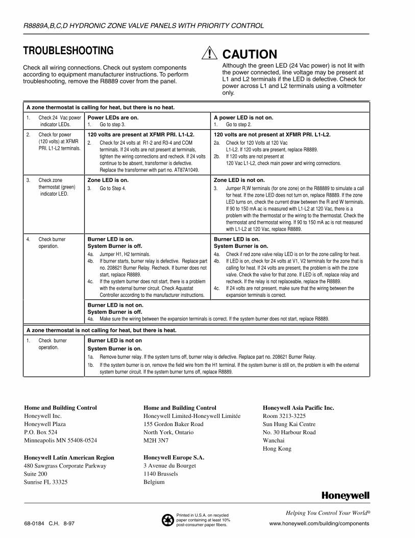
TROUBLESHOOTINGCheck all wiring connections. Check out system componentsaccording to equipment manufacturer instructions. To performtroubleshooting, remove the R8889 cover from the panel.
CAUTIONAlthough the green LED (24 Vac power) is not lit withthe power connected, line voltage may be present atL1 and L2 terminals if the LED is defective. Check forpower across L1 and L2 terminals using a voltmeteronly.
A zone thermostat is calling for heat, but there is no heat.
1. Check 24 Vac power indicator LEDs.
Power LEDs are on.1. Go to step 3.
A power LED is not on.1. Go to step 2.
2. Check for power (120 volts) at XFMRPRI. L1-L2 terminals.
120 volts are present at XFMR PRI. L1-L2.
2. Check for 24 volts at R1-2 and R3-4 and COMterminals. If 24 volts are not present at terminals,tighten the wiring connections and recheck. If 24 voltscontinue to be absent, transformer is defective.Replace the transformer with part no. AT87A1049.
120 volts are not present at XFMR PRI. L1-L2.
2a. Check for 120 Volts at 120 Vac L1-L2. If 120 volts are present, replace R8889.
2b. If 120 volts are not present at 120 Vac L1-L2, check main power and wiring connections.
3. Check zonethermostat (green)
indicator LED.
Zone LED is on.
3. Go to Step 4.
Zone LED is not on.
3. Jumper R,W terminals (for one zone) on the R88889 to simulate a callfor heat. If the zone LED does not turn on, replace R8889. If the zoneLED turns on, check the current draw between the R and W terminals.If 90 to 150 mA ac is measured with L1-L2 at 120 Vac, there is aproblem with the thermostat or the wiring to the thermostat. Check thethermostat and thermostat wiring. If 90 to 150 mA ac is not measuredwith L1-L2 at 120 Vac, replace R8889.
4. Check burneroperation.
Burner LED is on.System Burner is off.
4a. Jumper H1, H2 terminals. 4b. If burner starts, burner relay is defective. Replace part
no. 208621 Burner Relay. Recheck. If burner does notstart, replace R8889.
4c. If the system burner does not start, there is a problemwith the external burner circuit. Check AquastatController according to the manufacturer instructions.
Burner LED is on.System Burner is on.
4a. Check if red zone valve relay LED is on for the zone calling for heat.4b. If LED is on, check for 24 volts at V1, V2 terminals for the zone that is
calling for heat. If 24 volts are present, the problem is with the zonevalve. Check the valve for that zone. If LED is off, replace relay andrecheck. If the relay is not replaceable, replace the R8889.
4c. If 24 volts are not present, make sure that the wiring between theexpansion terminals is correct.
Burner LED is not on.System Burner is off.4a. Make sure the wiring between the expansion terminals is correct. If the system burner does not start, replace R8889.
A zone thermostat is not calling for heat, but there is heat.
1. Check burneroperation.
Burner LED is not on
System Burner is on.
1a. Remove burner relay. If the system turns off, burner relay is defective. Replace part no. 208621 Burner Relay.
1b. If the system burner is on, remove the field wire from the H1 terminal. If the system burner is still on, the problem is with the externalsystem burner circuit. If the system burner turns off, replace R8889.