Embed Size (px)
Citation preview

1
CT70Heat Pump
Thermostat Wiring Guide

2
3
HOW TO USE THIS GUIDE
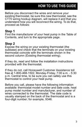
Before you disconnect the wires and remove your existing thermostat, be sure this new thermostat, see the CT70 wiring hookup diagram, will replace it and that you understand how you will reconnect the wiring. To do that, proceed as follows:
Step 1Find the manufacturer of your heat pump in the Table of Contents, and turn to the appropriate page.
Step 2Expose the wiring on your existing thermostat (the subbase) and check that the terminals on your existing thermostat coincide with the terminals shown in the second column (Existing thermostat wiring).
If they do, read and follow the installation instructions provided with the thermostat.
If they do not, call Honeywell Customer Assistance toll free at 1-800-468-1502, Monday-Friday, 7:00 a.m. - 5:30 p.m. Central time, to be sure you can safely use this thermostat to control your heat pump.
Before you call, please have the following information available: thermostat model number and date code, heat pump model number and manufacturer, and number of wires connected to the thermostat. The date code is usually stamped on the back of the thermostat and is a four-digit number; for example, 9346.

4
5
TABLE OF CONTENTS
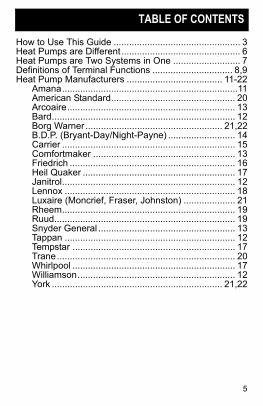
How to Use This Guide ................................................. 3Heat Pumps are Different .............................................. 6Heat Pumps are Two Systems in One .......................... 7Definitions of Terminal Functions ............................... 8,9Heat Pump Manufacturers ..................................... 11-22
Amana....................................................................11American Standard................................................ 20Arcoaire................................................................. 13Bard....................................................................... 12Borg Warner ..................................................... 21,22B.D.P. (Bryant-Day/Night-Payne) .......................... 14Carrier ................................................................... 15Comfortmaker ....................................................... 13Friedrich ................................................................ 16Heil Quaker ........................................................... 17Janitrol................................................................... 12Lennox .................................................................. 18Luxaire (Moncrief, Fraser, Johnston) .................... 21Rheem................................................................... 19Ruud...................................................................... 19Snyder General ..................................................... 13Tappan .................................................................. 12Tempstar ............................................................... 17Trane..................................................................... 20Whirlpool ............................................................... 17Williamson............................................................. 12York .................................................................. 21,22
6
HEAT PUMPS ARE DIFFERENT
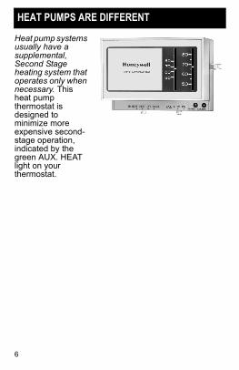
Heat pump systems usually have a supplemental, Second Stage heating system that operates only when necessary. This heat pump thermostat is designed to minimize more expensive second-stage operation, indicated by the green AUX. HEAT light on your thermostat.
7
HEAT PUMPS ARE TWO SYSTEMS IN ONE
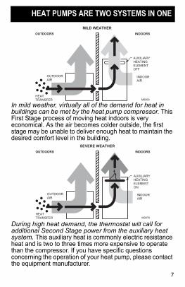
In mild weather, virtually all of the demand for heat in buildings can be met by the heat pump compressor. This First Stage process of moving heat indoors is very economical. As the air becomes colder outside, the first stage may be unable to deliver enough heat to maintain the desired comfort level in the building.
During high heat demand, the thermostat will call for additional Second Stage power from the auxiliary heat system. This auxiliary heat is commonly electric resistance heat and is two to three times more expensive to operate than the compressor. If you have specific questions concerning the operation of your heat pump, please contact the equipment manufacturer.
INDOORAIR
OUTDOORAIR
HEATTRANSFER
AUXILIARYHEATINGELEMENTOFF
OUTDOORS
MILD WEATHER
INDOORS
M9069
INDOORAIR
OUTDOORAIR
HEATTRANSFER
AUXILIARYHEATINGELEMENTON
OUTDOORS
SEVERE WEATHER
INDOORS
M9078
8
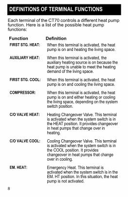
DEFINITIONS OF TERMINAL FUNCTIONS
Each terminal of the CT70 controls a different heat pump function. Here is a list of the possible heat pump functions:
Function DefinitionFIRST STG. HEAT: When this terminal is activated, the heat
pump is on and heating the living space.
AUXILIARY HEAT: When this terminal is activated, the auxiliary heating source is on because the heat pump is unable to meet the heating demand of the living space.
FIRST STG. COOL: When this terminal is activated, the heat pump is on and cooling the living space.
COMPRESSOR: When this terminal is activated, the heat pump is on and either heating or cooling the living space, depending on the system switch position.
C/O VALVE HEAT: Heating Changeover Valve. This terminal is activated when the system switch is in the HEAT position. It provides changeover in heat pumps that change over in heating.
C/O VALVE COOL: Cooling Changeover Valve. This terminal is activated when the system switch is in the COOL position. It provides changeover in heat pumps that change over in cooling.
EM. HEAT: Emergency Heat. This terminal is activated when the system switch is in the EM. HT position. In this situation, the heat pump is not activated.
9
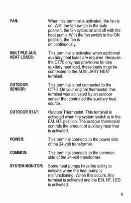
FAN: When this terminal is activated, the fan is on. With the fan switch in the auto position, the fan cycles on and off with the heat pump. With the fan switch in the ON position, the fan is on continuously.
MULTIPLE AUX. HEAT LOADS:
This terminal is activated when additional auxiliary heat loads are required. Because the CT70 only has provisions for one auxiliary heat load, these loads must be connected to the AUXILIARY HEAT terminal.
OUTDOOR SENSOR:
This terminal is not connected to the CT70. On your original thermostat, this terminal was activated by an outdoor sensor that controlled the auxiliary heat source.
OUTDOOR STAT: Outdoor Thermostat. This terminal is activated when the system switch is in the EM. HT. position. The outdoor thermostat controls the amount of auxiliary heat that is activated.
POWER: This terminal connects to the power side of the 24-volt transformer.
COMMON: This terminal connects to the common side of the 24-volt transformer.
SYSTEM MONITOR: Some heat pumps have the ability to indicate when the heat pump is malfunctioning. When this occurs, this terminal is activated and the EM. HT. LED is activated.
10
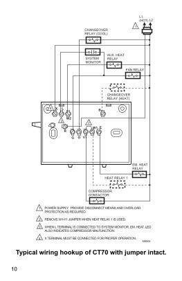
Typical wiring hookup of CT70 with jumper intact.
M8504
W2
W1
X
O
E
G Y1
R
L B
L1 (HOT) L2
1
POWER SUPPLY. PROVIDE DISCONNECT MEANS AND OVERLOAD PROTECTION AS REQUIRED.
REMOVE W1-Y1 JUMPER WHEN HEAT RELAY 1 IS USED.
WHEN L TERMINAL IS CONNECTED TO SYSTEM MONITOR, EM. HEAT. LED ALSO INDICATES COMPRESSOR MALFUNCTION.
X TERMINAL MUST BE CONNECTED FOR PROPER OPERATION.
1
2
3
4
COMPRESSORCONTACTOR
FAN RELAY
EM. HEATRELAY
CHANGEOVERRELAY (HEAT)
HEAT RELAY 1
CHANGEOVERRELAY (COOL)
AUX. HEAT RELAYSYSTEM
MONITOR
23
4
11
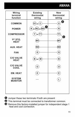
AMANA
! Jumper these two terminals if both are present# This terminal must be connected to transformer common.$ Remove this factory-installed jumper for independent stage 1
heat and cool connection.
W1
Wiringterminalfunction
Existingthermostat
wiring
Newthermostat
wiring
COMMON
POWER
COMPRESSOR
1ST STG.HEAT
AUX. HEAT
FAN
C/O VALVEHEAT
C/O VALVECOOL
EM. HEAT
SYSTEMMONITOR
W1
W2 W2
G G
O O
L
3
C X2
X1 or
RH RRC orR or1
Y1 Y1Y or
BB or
E E
W
12
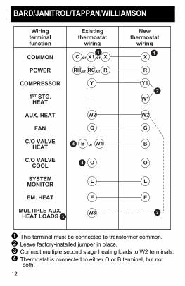
BARD/JANITROL/TAPPAN/WILLIAMSON
! This terminal must be connected to transformer common.# Leave factory-installed jumper in place.$ Connect multiple second stage heating loads to W2 terminals.% Thermostat is connected to either O or B terminal, but not
both.
Wiringterminalfunction
Existingthermostat
wiring
Newthermostat
wiring
COMMON
POWER
COMPRESSOR
1ST STG.HEAT
AUX. HEAT
FAN
C/O VALVEHEAT
C/O VALVECOOL
SYSTEMMONITOR
EM. HEAT
MULTIPLE AUX.HEAT LOADS
W1
W2 W2
G G
2
X XX1 orC or
1
E E
1
Y Y1
L L
B
O
W3 3
R RRC orRH or
W1B or
3
4
4 O
13
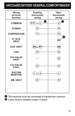
ARCOAIRE/SNYDER GENERAL/COMFORTMAKER
! This terminal must be connected to transformer common.# Leave factory-installed jumper in place.
Wiringterminalfunction
Existingthermostat
wiring
Newthermostat
wiring
COMMON
POWER
COMPRESSOR
1ST STG.HEAT
AUX. HEAT
FAN
C/O VALVEHEAT
C/O VALVECOOL
SYSTEMMONITOR
EM. HEAT
C X
R R
Y Y1
W1
W1 W2
G G
O O
B
1
2
1
X L
E E
W2 or
L or
X,X1 or
14
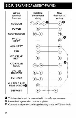
B.D.P. (BRYANT-DAY/NIGHT-PAYNE)
! This terminal must be connected to transformer common.# Leave factory-installed jumper in place.$ Connect multiple second stage heating loads to W2 terminals.
Wiringterminalfunction
Existingthermostat
wiring
Newthermostat
wiring
COMMON
POWER
COMPRESSOR
1ST STG.HEAT
AUX. HEAT
FAN
C/O VALVEHEAT
C/O VALVECOOL
SYSTEMMONITOR
EM. HEAT
MULTIPLE AUX.HEAT LOADS
DEFROST
R R
Y Y1
W1
W2 W2
G G
O O
F L
E E
B B
W3
P P
2
3
C1
X
or
W1
Y1
X
L or
or
or
or
3
C1 X1 or1
15
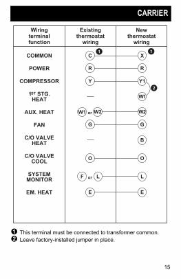
CARRIER
! This terminal must be connected to transformer common.# Leave factory-installed jumper in place.
Wiringterminalfunction
Existingthermostat
wiring
Newthermostat
wiring
COMMON
POWER
COMPRESSOR
1ST STG.HEAT
AUX. HEAT
FAN
C/O VALVEHEAT
C/O VALVECOOL
SYSTEMMONITOR
EM. HEAT
C X
R R
Y Y1
W1
W2 W2
G G
O O
B
1
2
1
L L
E E
F
W1 or
or
16
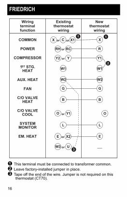
FRIEDRICH
! This terminal must be connected to transformer common.# Leave factory-installed jumper in place.$ Tape off the end of the wire. Jumper is not required on this
thermostat (CT70).
Wiringterminalfunction
Existingthermostat
wiring
Newthermostat
wiring
COMMON
POWER
COMPRESSOR
1ST STG.HEAT
AUX. HEAT
FAN
C/O VALVEHEAT
C/O VALVECOOL
SYSTEMMONITOR
EM. HEAT
W1
W2 W2
G G
2
X1
X2 E
1
R
Y Y1
W1
B B
U3
RCRH or
C
Y1 O
L L
or
X1X or or
Y2
E
O
W3
or
or
or
17
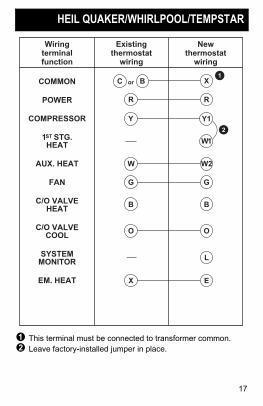
HEIL QUAKER/WHIRLPOOL/TEMPSTAR
! This terminal must be connected to transformer common.# Leave factory-installed jumper in place.
Wiringterminalfunction
Existingthermostat
wiring
Newthermostat
wiring
COMMON
POWER
COMPRESSOR
1ST STG.HEAT
AUX. HEAT
FAN
C/O VALVEHEAT
C/O VALVECOOL
SYSTEMMONITOR
EM. HEAT
B X
R R
W W2
G G
O O
1
L
X E
B B
Y Y1
W1
2
C or
18
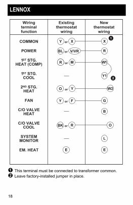
LENNOX
! This terminal must be connected to transformer common.# Leave factory-installed jumper in place.
R
Wiringterminalfunction
Existingthermostat
wiring
Newthermostat
wiring
COMMON
POWER
1ST STG.HEAT (COMP)
1ST STG.COOL
2ND STG.HEAT
FAN
C/O VALVEHEAT
C/O VALVECOOL
SYSTEMMONITOR
EM. HEAT
X X
Y W2
1
E E
L
M W1
B
V/VR
Y12
F G
R O
orY
BL or
R or
Y
R
O
BK
or
or
or
19
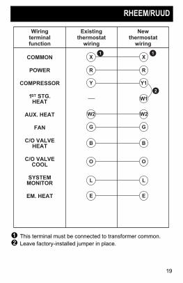
RHEEM/RUUD
! This terminal must be connected to transformer common.# Leave factory-installed jumper in place.
Wiringterminalfunction
Existingthermostat
wiring
Newthermostat
wiring
COMMON
POWER
COMPRESSOR
1ST STG.HEAT
AUX. HEAT
FAN
C/O VALVEHEAT
C/O VALVECOOL
SYSTEMMONITOR
EM. HEAT
X X
R R
Y Y1
W1
W2 W2
G G
O O
1
2
1
L L
E E
B B
20
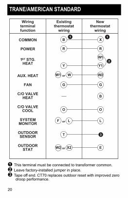
TRANE/AMERICAN STANDARD
! This terminal must be connected to transformer common.# Leave factory-installed jumper in place.$ Tape off end. CT70 replaces outdoor reset with improved zero
droop performance.
Wiringterminalfunction
Existingthermostat
wiring
Newthermostat
wiring
COMMON
POWER
1ST STG.HEAT
AUX. HEAT
FAN
C/O VALVEHEAT
C/O VALVECOOL
SYSTEMMONITOR
OUTDOORSENSOR
OUTDOORSTAT
B X
R R
W W2
G G
O O
1
Y Y1
W1
B
L L
T
X2 E
1
2
3
W1
W2
F
or
or
or
21
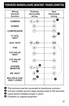
YORK/BORG WARNER/LUXAIRE (MONCRIEF, FRASER-JOHNSTON)
! This terminal must be connected to transformer common.# Connect multiple second stage heating loads to W2 terminals.$ Leave factory-installed jumper in place.% If present on original equipment.
Wiringterminalfunction
Existingthermostat
wiring
Newthermostat
wiring
COMMON
POWER
COMPRESSOR
1ST STG.HEAT
AUX. HEAT
FAN
C/O VALVEHEAT
C/O VALVECOOL
SYSTEMMONITOR
EM. HEAT
MULTIPLE AUX. HEAT LOADS
W1
W2 W2
G G
3
Y Y1
H B
W3
O O
L L
RR
4
E E
4
2
4
or
orX
1XorX B
W
22
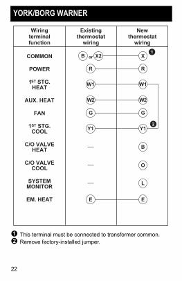
YORK/BORG WARNER
! This terminal must be connected to transformer common.# Remove factory-installed jumper.
Wiringterminalfunction
Existingthermostat
wiring
Newthermostat
wiring
COMMON
POWER
1ST STG.HEAT
AUX. HEAT
FAN
1ST STG.COOL
C/O VALVEHEAT
C/O VALVECOOL
SYSTEMMONITOR
EM. HEAT
X2 X
R R
W1 W1
G G
Y1 Y12
1
B
W2 W2
O
L
E E
orB

23

69-0866�2 C.H. Rev. 01-95 www.honeywell.com/yourhome
Automation and Control SolutionsHoneywell International Inc.1985 Douglas Drive NorthGolden Valley, MN 55422