Embed Size (px)
Citation preview
i
i
PEC624: M.Sc. Dissertation
Do Hybrid Compressed Air Energy Storage (HCAES) Systems Offer a Viable
Alternative Solution to Energy Storage Requirements for Small to Medium Size
Renewable Energy Systems?
Jan Muller
A dissertation submitted in partial fulfilment of the requirements for the degree of
Master of Science in Renewable Energy, Murdoch University.
Faculty of Minerals and Energy, School of Energy and Engineering,
Murdoch University
November 2009

ii
ii
Declaration of originality
This is to certify that the work is entirely my own and not of any other person, unless
explicitly acknowledged (including citation of published and unpublished sources). The
work has not previously been submitted in any form to the Murdoch University or to
any other institution for assessment or for any other purpose.
Signed _________________________________________________
Date ___________________________________________________
iii
iii
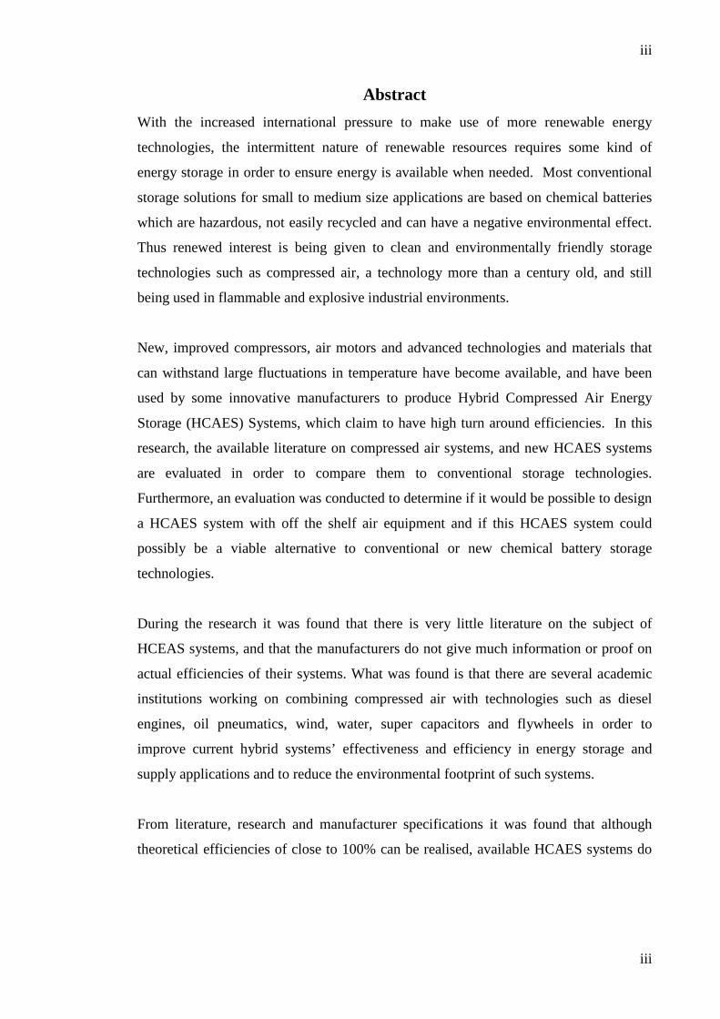
Abstract With the increased international pressure to make use of more renewable energy
technologies, the intermittent nature of renewable resources requires some kind of
energy storage in order to ensure energy is available when needed. Most conventional
storage solutions for small to medium size applications are based on chemical batteries
which are hazardous, not easily recycled and can have a negative environmental effect.
Thus renewed interest is being given to clean and environmentally friendly storage
technologies such as compressed air, a technology more than a century old, and still
being used in flammable and explosive industrial environments.
New, improved compressors, air motors and advanced technologies and materials that
can withstand large fluctuations in temperature have become available, and have been
used by some innovative manufacturers to produce Hybrid Compressed Air Energy
Storage (HCAES) Systems, which claim to have high turn around efficiencies. In this
research, the available literature on compressed air systems, and new HCAES systems
are evaluated in order to compare them to conventional storage technologies.
Furthermore, an evaluation was conducted to determine if it would be possible to design
a HCAES system with off the shelf air equipment and if this HCAES system could
possibly be a viable alternative to conventional or new chemical battery storage
technologies.
During the research it was found that there is very little literature on the subject of
HCEAS systems, and that the manufacturers do not give much information or proof on
actual efficiencies of their systems. What was found is that there are several academic
institutions working on combining compressed air with technologies such as diesel
engines, oil pneumatics, wind, water, super capacitors and flywheels in order to
improve current hybrid systems’ effectiveness and efficiency in energy storage and
supply applications and to reduce the environmental footprint of such systems.
From literature, research and manufacturer specifications it was found that although
theoretical efficiencies of close to 100% can be realised, available HCAES systems do
iv
iv
not offer such an effective or efficient solution as chemical battery systems. In addition
off the shelf compressors and motors that can be used to design a HCAES system have
been manufactured to give high performance and torque with low efficiencies. The
efficiency is further drastically reduced as the storage pressure is increased, which is
necessary to decrease storage vessel requirements.

v
v
Word Count
Number of Pages: 53
Number of Words: 10364
Acknowledgements I would like to thank the following persons who have helped and supported me during
my research and writing of my dissertation. The first is Dr Pryor who must have found
it a stretch in accommodating and supporting an off campus student from South Africa.
I truly appreciate the work you and all your colleagues are doing in offering the rest of
the world a chance to get the knowledge and experience to make a difference. Next, my
local supervisor Peter Langley and his associate Pat Framton, energy storage specialist
from Eskom research and development, who made me sweat to ensure my dissertation
is on par with world standards.
Then a special thanks to two of my colleagues, Michelle Redelinghuys and Paul Davel,
both chief engineers, who helped to improve this document by making suggestions
regarding its content, style and grammar to ensure that this work is of acceptable
standard and quality. Another colleague who made it possible was Jakes Thompson, a
DC specialist, who in his hectic schedule provided the DC back-up specifications of
Brakfontein repeater station.
Lastly I would like to thank my wife, son and daughter, who had to give up precious
family time with me over the past three years allowing me to achieve my dream, and
without whose support I could never have achieved this important goal in my life.
vi
vi
Table of Contents
CHAPTER 1 ..................................................................................................................... 1
INTRODUCTION ............................................................................................................ 1
1.1: Compressed Air Background ................................................................................. 1
1.2: Study Area ............................................................................................................. 4
1.3: Dissertation Structure ............................................................................................. 4
1.4: Aim and Objectives ................................................................................................ 5
CHAPTER 2 ..................................................................................................................... 8
LITERATURE REVIEW.................................................................................................. 8
2.1: Introduction ............................................................................................................ 8
2.2: Compressed Air Research ...................................................................................... 8
2.3: Compressed Air Literature ................................................................................... 13
CHAPTER 3 ................................................................................................................... 14
METHODS AND DATA ................................................................................................ 14
3.1: Introduction .......................................................................................................... 14
3.2: Analysis of Installed Energy Storage Technologies ............................................ 14
3.3: Hybrid Compressed Air Energy Storage ............................................................. 18
3.4: Brakfontein Repeater Station ............................................................................... 23
3.5: Selected HCAES Equipment for Design ............................................................. 24
3.5.1: High Pressure Compressor ............................................................................ 24
3.5.2: Alternator ...................................................................................................... 26
3.5.3: Air Motor ...................................................................................................... 26
3.5.4: Air Storage .................................................................................................... 27
3.5.5: Bridging Power ............................................................................................. 28
3.5.6: Inverter and Control System ......................................................................... 28
3.6: Selected HCAES Equipment for Design ............................................................. 29
3.7: Methods and techniques ....................................................................................... 30
CHAPTER 4 ................................................................................................................... 32
RESULTS FROM ANALYSIS OF PROPOSED DESIGN ........................................... 32
4.1: Introduction .......................................................................................................... 32
vii
vii
4.2: Results from Boyle Calculations ......................................................................... 32
4.3: Stored Air Energy Calculations ........................................................................... 33
4.4: Compressed Air System Efficiency Calculations ................................................ 34
4.5: Discussion of results ............................................................................................ 34
DISCUSSION ................................................................................................................. 36
5.1: Introduction .......................................................................................................... 36
5.2: Discussion ............................................................................................................ 36
CHAPTER 6 ................................................................................................................... 39
CONCLUSIONS ............................................................................................................. 39
6.1: Conclusions .......................................................................................................... 39
6.2: Recommendations ................................................................................................ 40
APPENDICES ................................................................................................................ 41
1
1
CHAPTER 1
INTRODUCTION
1.1: Compressed Air Background
Compressed Air Energy Storage (CAES) refers to a method used to store energy for
later use, by compression and storage of air. Due to the increasing use of renewable
energy (RE) technologies, and the intermittent nature of the energy sources that these
technologies are based on, energy storage has become one of the main challenges
that needed to be resolved in order to improve the reliability and acceptance of the
renewable technologies.
For small, remote applications chemical battery storage systems are used in all but a
few research installations which utilise experimental technologies such as hydrogen
storage. Large, grid-connected peak storage applications have to date been based on
Hydro Pump Storage Systems. There are also two CAES systems in operation: one in
Huntorf, in Bremen, Germany, which was built in 1978, and the other, McIntosh
plant in Alabama, U.S.A., built in 1991. Due to limited locations available for Hydro
Pump Storage systems, CAES systems are gaining more attention as a way to
address the challenges experienced with the variable nature of wind.
2
2
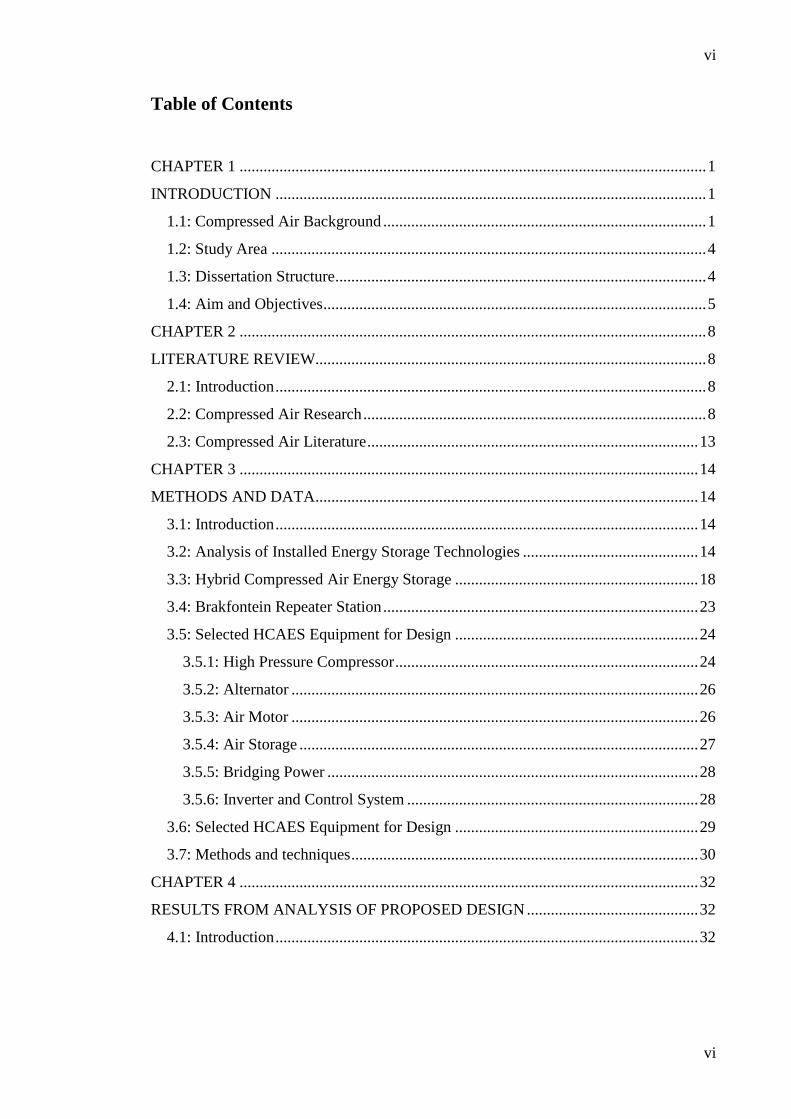
Figure 2: Conceptual representation of CAES (source: http://www.caes.net/)
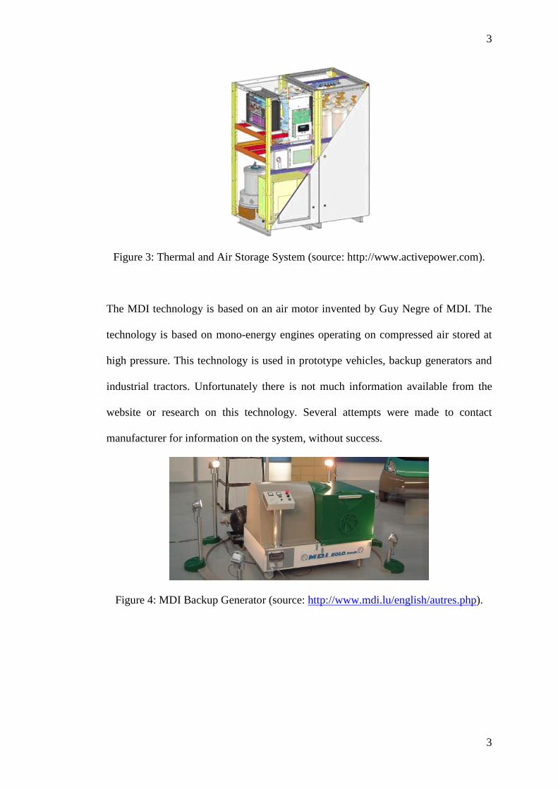
Increased attention and research are being focused on compressed air technology in
order to replace chemical batteries for smaller energy storage applications. Some of
the commercial products that are currently available are the thermal and compressed
air storage (TACAS) system and the Motor Development International (MDI)
generator unit. The TACAS system is an 80 kW uninterrupted power supply (UPS)
which can deliver 80 kW for 15 minutes. It is a combination of air, thermal storage
and a flywheel. It requires 20 m³ of air a minute or 300 m³ for 15 minutes.
3
3
Figure 3: Thermal and Air Storage System (source: http://www.activepower.com).
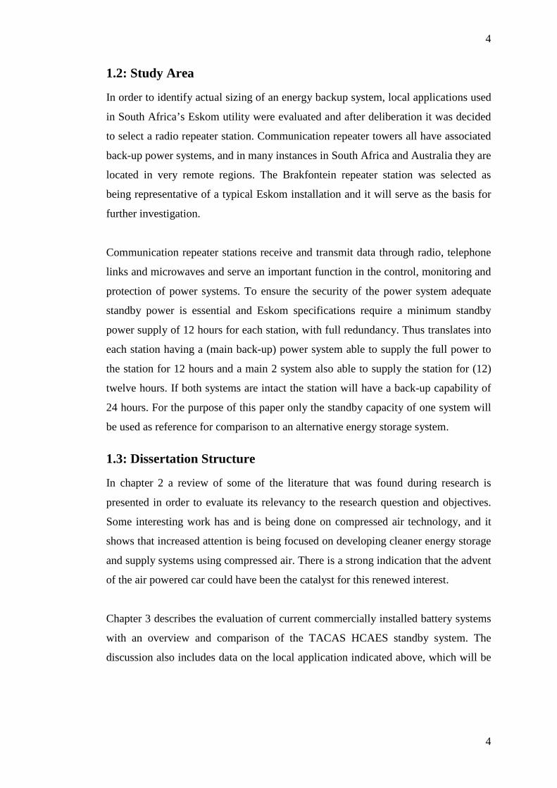
The MDI technology is based on an air motor invented by Guy Negre of MDI. The
technology is based on mono-energy engines operating on compressed air stored at
high pressure. This technology is used in prototype vehicles, backup generators and
industrial tractors. Unfortunately there is not much information available from the
website or research on this technology. Several attempts were made to contact
manufacturer for information on the system, without success.
Figure 4: MDI Backup Generator (source: http://www.mdi.lu/english/autres.php).
4
4
1.2: Study Area
In order to identify actual sizing of an energy backup system, local applications used
in South Africa’s Eskom utility were evaluated and after deliberation it was decided
to select a radio repeater station. Communication repeater towers all have associated
back-up power systems, and in many instances in South Africa and Australia they are
located in very remote regions. The Brakfontein repeater station was selected as
being representative of a typical Eskom installation and it will serve as the basis for
further investigation.
Communication repeater stations receive and transmit data through radio, telephone
links and microwaves and serve an important function in the control, monitoring and
protection of power systems. To ensure the security of the power system adequate
standby power is essential and Eskom specifications require a minimum standby
power supply of 12 hours for each station, with full redundancy. Thus translates into
each station having a (main back-up) power system able to supply the full power to
the station for 12 hours and a main 2 system also able to supply the station for (12)
twelve hours. If both systems are intact the station will have a back-up capability of
24 hours. For the purpose of this paper only the standby capacity of one system will
be used as reference for comparison to an alternative energy storage system.
1.3: Dissertation Structure
In chapter 2 a review of some of the literature that was found during research is
presented in order to evaluate its relevancy to the research question and objectives.
Some interesting work has and is being done on compressed air technology, and it
shows that increased attention is being focused on developing cleaner energy storage
and supply systems using compressed air. There is a strong indication that the advent
of the air powered car could have been the catalyst for this renewed interest.
Chapter 3 describes the evaluation of current commercially installed battery systems
with an overview and comparison of the TACAS HCAES standby system. The
discussion also includes data on the local application indicated above, which will be
5
5
used to give a credible idea of the energy storage requirements in a practical
application. Finally, the chapter describes the available equipment that could be used
to design an off-the-shelf HCAES system.
Chapter 4 includes the analysis and results of efficiency calculations on a practical
CAES design, based on information from air equipment manufacturers’ specification
sheets. The analysis and findings are then discussed in Chapter 5, with conclusions
and recommendations in Chapter 6.
1.4: Aim and Objectives
Energy storage is one of the main challenges to overcome in order to support
renewable energy technology due to the intermittent nature of the majority of
primary renewable energy sources. There is an ongoing research on these energy
storage systems to improve their efficiencies, energy storage capacity and density.
“Energy storage in a power system can be defined as any installation or method,
usually subject to independent control, with the help of which it is possible to store
energy, generated in a power system, keep it stored and use it in the power system
when necessary (source: Energy Storage for Power Systems, A. Ter-Gazian and
Pieter Peregrinus, 1994).
There is a lot of ongoing work and research being done in comparing energy storage
technologies. Each technology has inherent advantages, disadvantages and
limitations. Well known technologies, such as different chemical batteries, hydro
pumped storage and to some extent compressed air energy storage are used within
the power industry. Newer technologies such as flow batteries, flywheels, super
capacitors, super conducting magnetic energy storage, hydrogen energy storage and
thermal energy storage are being introduced into the market as they become more
viable arising from advances in technology, cost and political pressures.
Within the energy storage research increased attention is being applied to a
technology based on compressed air energy storage for smaller energy storage
6
6
applications, such as stand-by generation and uninterrupted power supplies. From the
research literature found, there is a strong suggestion that renewed interest has
originated from research and development of air powered cars, which has driven
advances in technology that led to development of more efficient air compressors
and motors. This technology, unlike the existing CAES technology which still
utilises fuel in the power generation cycle, combines other technologies such as
flywheels, super capacitors and heat storage to improve efficiencies and overcome
some of the disadvantages and limitations of the existing commercially available
systems. The combination of technologies can be seen as a hybrid of different energy
storage technologies, and is therefore called a Hybrid Compressed Air Energy
Storage System (HCAES). Due to the fact that it has only been introduced very
recently, there is very little comparative data with regard to conventional energy
storage technologies.
Therefore, in order to evaluate whether a HCAES system could offer a viable
alternative solution to the energy storage requirements of small to medium sized
renewable energy systems, the following objectives were set in order to provide
sufficient evidence to either support or refute the research question:
• Research and report on available air energy storage and delivery methods.
• Understand challenges of utilising compressed air as the energy storage
medium.
• Understand theoretical and practical implications of the thermodynamics of
compressed air systems.
• Evaluate existing or experimental HCAES technologies in order to identify
the most practical technologies that could be used to develop a locally
produced HCAES system.
• Gather and analyse data on the energy storage requirements of a selected
local application requiring a back-up power supply system.
• Use the data and the identified compressed air technology to design a
HCAES system.
• Compare the HCAES design with the existing back-up system.
7
7
• Compare costs associated with both installations. (This relates to the viability
aspect).
From the above objectives some literature study was required in order to find the
most relevant information available that would support or refute the main research
question or could serve as guidance on how to design a HCAES system that could be
used to replace conventional chemical batteries.
8
8
CHAPTER 2
LITERATURE REVIEW
2.1: Introduction
In order to better understand contemporary HCAES technology and research it was
important to perform a literature review of existing papers, books and other research
material. The largest information resource available was the internet, with a few
selected textbooks on energy storage available in academic and utility libraries. The
information found on the internet on the topic of HCAES was limited and mostly
based on ongoing research, with some researchers advertising HCAES technology
for UPS and standby power generation applications, making claims of high turn
around efficiencies without offering credible supporting evidence.
2.2: Compressed Air Research
Principle of Hybrid Energy Storage Systems based on Hydro-pneumatics and
Super-capacitors for Distributed Generation and Renewable Energy Sources
support. Written by S. Lemofouet and A. Rufer. Industrial Electronics Laboratory
(LEI) - Swiss Federal Institute of Technology (EPFL). 2005. Accessed: 20 June
2009. Webpage: leiwww.epfl.ch/publications/lemofouet_rufer_eesat_05.pdf
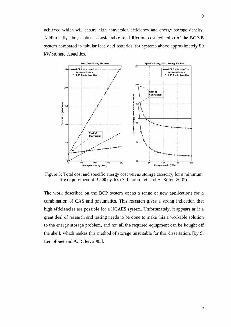
The paper by Lemofouet and Rufer explains the functioning of a very innovative
energy storage system based on hydro-pneumatics and super-capacitors, and
compares the cost of the system to tubular lead acid battery system. It is interesting
to note that compression and decompression is achieved using liquid cylinders (oil)
and is called the “Batteries with Oil-hydraulics and Pneumatics (BOP)” system. The
paper describes two systems, the BOP-A which was lab tested and proved the
fundamental principles, and the BOP-B system where compression and expansion of
fresh air is done in liquid piston work chambers with integrated heat exchangers. The
authors claim that by using the liquid pistons an almost ideal isothermal process is
9
9
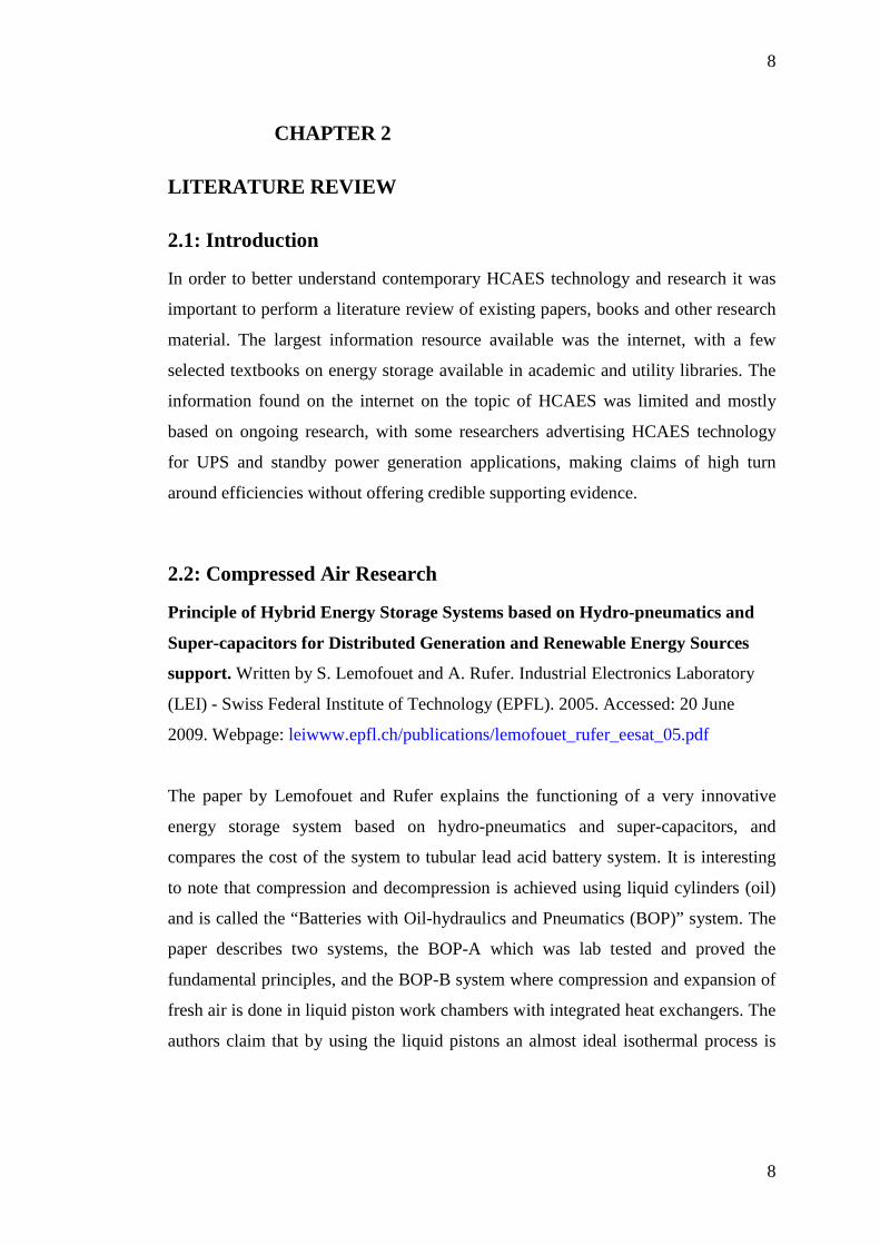
achieved which will ensure high conversion efficiency and energy storage density.
Additionally, they claim a considerable total lifetime cost reduction of the BOP-B
system compared to tubular lead acid batteries, for systems above approximately 80
kW storage capacities.
Figure 5: Total cost and specific energy cost versus storage capacity, for a minimum
life requirement of 3 500 cycles (S. Lemofouet and A. Rufer, 2005).
The work described on the BOP system opens a range of new applications for a
combination of CAS and pneumatics. This research gives a strong indication that
high efficiencies are possible for a HCAES system. Unfortunately, it appears as if a
great deal of research and testing needs to be done to make this a workable solution
to the energy storage problem, and not all the required equipment can be bought off
the shelf, which makes this method of storage unsuitable for this dissertation. [by S.
Lemofouet and A. Rufer, 2005].
10
10
Figure 6: BOP-B Working Principal (S. Lemofouet and A. Rufer, 2005)
Study of a Hybrid Wind-Diesel System with Compressed Air Energy Storage.
Written by Hussein Ibrahim et al. 25 October 2007. IEEE. Electrical Power
Conference 2007. Accessed: 21 June 2009. Webpage:
www.ryounes.net/publications/IEEE2006.pdf
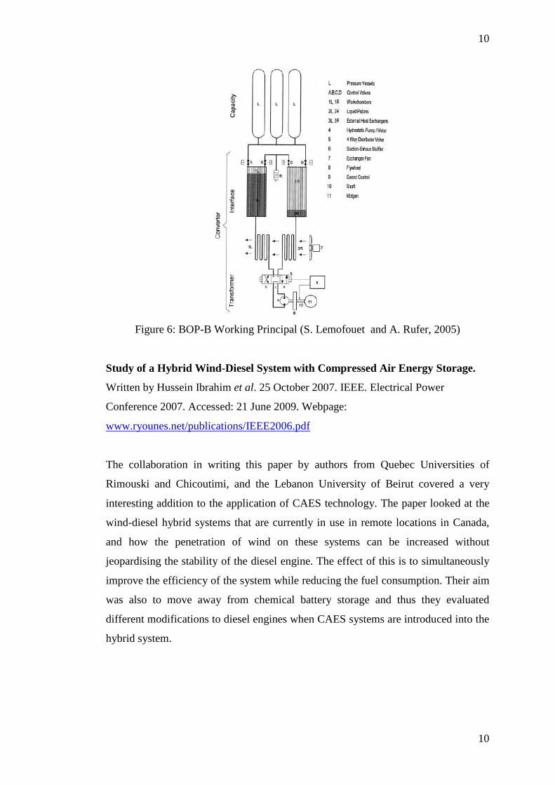
The collaboration in writing this paper by authors from Quebec Universities of
Rimouski and Chicoutimi, and the Lebanon University of Beirut covered a very
interesting addition to the application of CAES technology. The paper looked at the
wind-diesel hybrid systems that are currently in use in remote locations in Canada,
and how the penetration of wind on these systems can be increased without
jeopardising the stability of the diesel engine. The effect of this is to simultaneously
improve the efficiency of the system while reducing the fuel consumption. Their aim
was also to move away from chemical battery storage and thus they evaluated
different modifications to diesel engines when CAES systems are introduced into the
hybrid system.

11
11
This proposed Hybrid wind-diesel-CAES system directly supports the research
question of this paper, and furthermore gives a strong indication of the renewed
interest in compressed air technology. The solution proposed by the authors
definitely holds a lot of value to existing diesel hybrid systems. The proposal is to
use excess energy from wind-diesel system to store compressed air, which will then
be used to assist the turbo-charger of the diesel via a directly coupled air turbine
during low and fluctuating loads when there is not enough exhaust gas for the turbo
charger to assist the engine. The compressed air can also be used to run a diesel
engine quickly up to running speed. The paper claims that adding the CAES system
to the existing hybrid can increase the diesel engine power by a factor of 5. [Hussein
Ibrahim et al, 2007].
Figure 7: Illustration of the WDSAC with the Compressed Air Storage (CAS) turbine
connected to turbocharger shaft (Hussein Ibrahim et al, 2007)
New Technology and Possible Advances in Energy Storage. Writen by John
Baker. Ea Technology Ltd. Elsevier. 4 November 2008. Accessed: 20 June 2009.
Webapge: http://ideas.repec.org/a/eee/enepol/v36y2008i12p4368-4373.html
This paper covers existing and possible future advances on energy storage systems.
The following technologies are covered in the paper:
• Electrochemical Systems (batteries and flow cells).
• Kinetic Energy Systems (flywheels).
• Potential Energy Systems (pump storage and CAES).
12
12
The paper focuses mostly on advances made in the field of electrochemical storage
systems with very little on the Potential Energy Systems, although he predicts a
medium to high probability that there will be an increased uptake of these
technologies in the market. The author indicates that development in the core storage
technologies will be facilitated by advances in materials science, engineering,
processing and fabrication. The paper also postulates that future energy storage
technologies will be expected to offer improved energy and power densities, but
predicts that in practice gains in longevity, cycle expectancy and cost may be more
significant. The paper only looked at the large scale applications of Potential Energy
Systems, and did not consider smaller applications which are definitely receiving
increased attention from many researchers and developers. His prediction that the
practicalities of energy storage systems can be seen as very valid with regards to
HCEAS for small scale applications, when considering that compressed air systems
have no cycle limitations and have the same lifetime expectancy as that of the
application or energy system itself [John Baker, 2009].
Thermodynamic Analysis of Compressed Air Vehicle Propulsion. Written by Ulf
Bossel. European Fuel Cell Forum. Accessed: 19 June 2009. Webpage:
www.efcf.com/reports/E14.pdf
In his research paper Bossel evaluated claims made by the developers of air cars such
as MDI and the subsequent questions regarding the performance of these vehicles by
car manufacturers and automobile experts. The approach used was to calculate the
actual efficiency and design that will be required for such a car to be effective. The
theoretical analysis of the compression and later utilisation of the air showed that
both sides are partially correct. The calculations in the paper showed that filling a
300 l tank with air at 20 °C and 300 bar would result in the storage of 51 MJ of
energy. Under ideal reversible isothermal conditions this energy can be completely
converted to mechanical work. However, under isentropic conditions not more than
25 MJ can be used for work, which yields an efficiency of 50%. The paper shows
that through multistage compression with inter cooling between stages and using
multistage decompression with inter-stage heating the expansion process can be
13
13
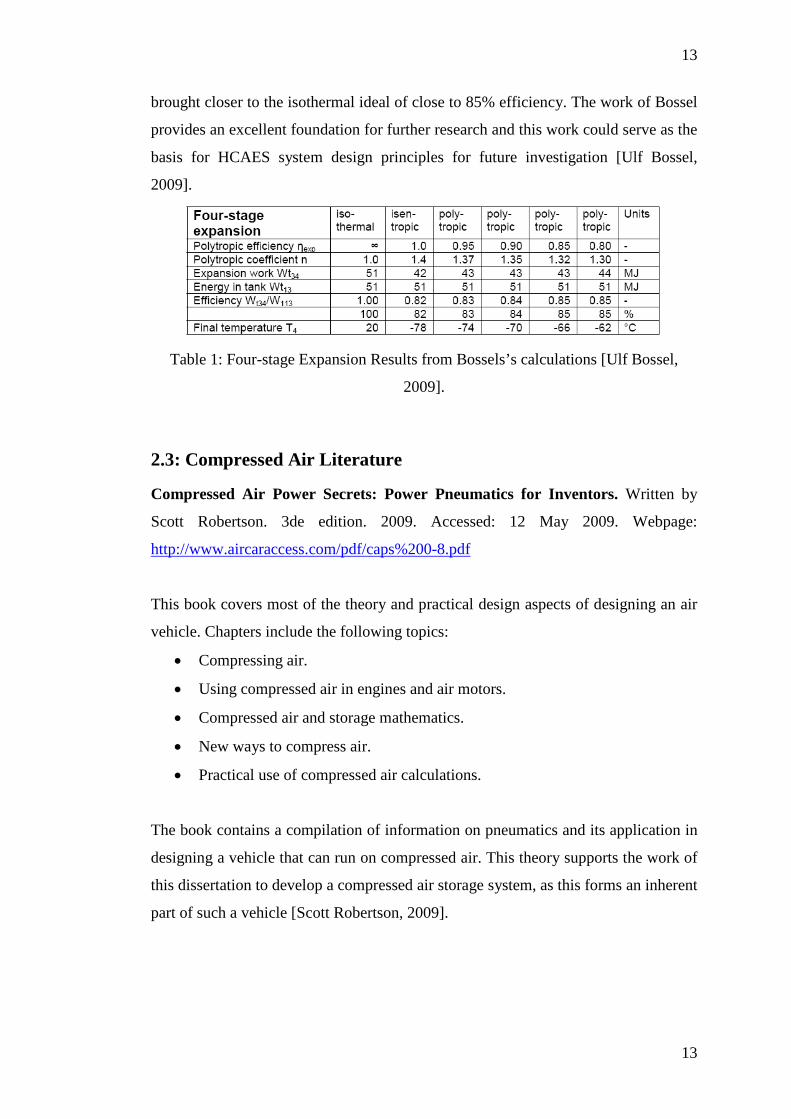
brought closer to the isothermal ideal of close to 85% efficiency. The work of Bossel
provides an excellent foundation for further research and this work could serve as the
basis for HCAES system design principles for future investigation [Ulf Bossel,
2009].
Table 1: Four-stage Expansion Results from Bossels’s calculations [Ulf Bossel,
2009].
2.3: Compressed Air Literature
Compressed Air Power Secrets: Power Pneumatics for Inventors. Written by
Scott Robertson. 3de edition. 2009. Accessed: 12 May 2009. Webpage:
http://www.aircaraccess.com/pdf/caps%200-8.pdf
This book covers most of the theory and practical design aspects of designing an air
vehicle. Chapters include the following topics:
• Compressing air.
• Using compressed air in engines and air motors.
• Compressed air and storage mathematics.
• New ways to compress air.
• Practical use of compressed air calculations.
The book contains a compilation of information on pneumatics and its application in
designing a vehicle that can run on compressed air. This theory supports the work of
this dissertation to develop a compressed air storage system, as this forms an inherent
part of such a vehicle [Scott Robertson, 2009].
14
14
CHAPTER 3
METHODS AND DATA
3.1: Introduction
In order to evaluate the HCAES technology and compare it to existing energy storage
technologies, it was important to first look at what is required from an ideal energy
storage system and then to do an evaluation on the presently existing technologies.
Important evaluation criteria are the cost of these technologies and their limitations.
This analysis can then be used to formulate a possible HCAES design that could be
locally built and would be reasonably priced and overcome the shortcomings of the
presently available systems.
Equipment specifications for the components of the proposed HCAES design were
then used to develop a theoretical model of the system. This model was then tested
against the stand-by power requirements of the selected communications repeater
station, which is presently supplied from a battery based system. This equipment data
includes information on technologies such as air motors, alternators, converters and
short-term battery storage.
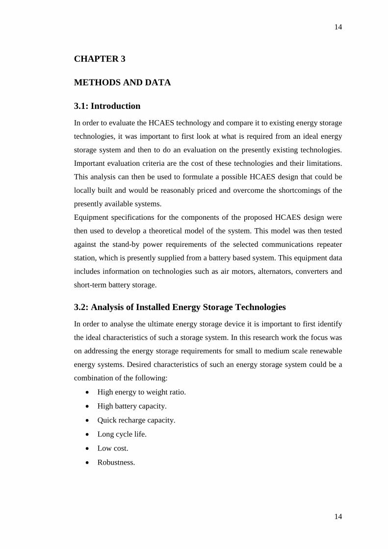
3.2: Analysis of Installed Energy Storage Technologies
In order to analyse the ultimate energy storage device it is important to first identify
the ideal characteristics of such a storage system. In this research work the focus was
on addressing the energy storage requirements for small to medium scale renewable
energy systems. Desired characteristics of such an energy storage system could be a
combination of the following:
• High energy to weight ratio.
• High battery capacity.
• Quick recharge capacity.
• Long cycle life.
• Low cost.
• Robustness.

15
15
• Simple to maintain.
• Fast response.
• Current fluctuation tolerance.
• Low self discharge rate.
• Low effect of temperature.
• High cell or battery voltage.
• High turn-around efficiency.
• High depth of discharge.
• Low environmental impact.
• High safety factor.
It is important to identify the specific functional requirements that apply to a small or
medium sized energy storage system. Functional requirements can be grouped into
three main categories:
• Power Quality – provide energy for a second or less to ensure continuity of
supply in response to system transients.
• Bridging Power – provide energy for seconds to a few minutes to ensure
supply continuity while switching from one power source to another.
• Energy Management – in this application energy generation and
consumption are de-coupled. Energy is stored when excess energy is
available or cheap and used when energy is not available or expensive.
(Ref: http://electricitystorage.org/tech/technologies_comparisons_ratings.htm)
In the case of small to medium scale energy storage applications for renewable or
back-up systems, at least two of the above functionalities will be required. The power
quality or bridging component will depend on the type of energy storage technology
and the required response time. Then the main energy management component,
which will supply the load when energy supply is not available or disconnected, will
always be required.

16
16
For the purposes of this document, the range of energy storage devices falling into
the category “small to medium sized” is assumed to range from 1 kW to
approximately 1 000 kW. The figure below indicates the performance of a number of
commercially installed storage applications with respect to their time of discharge
and rated power.
Figure 8: Energy Storage System Rating Comparison (source:
http://electricitystorage.org/tech/technologies_comparisons_ratings.htm).
Based on the information in Figure 8 the most obvious technologies for small scale
applications (less than 100 kW), which best satisfy the requirements of supply
quality or bridging power are the following [Electricity Storage Association, 2003]:
• Nickel-metal hydride battery.
• Lithium-ion battery.
• Vanadium redox battery.
17
17
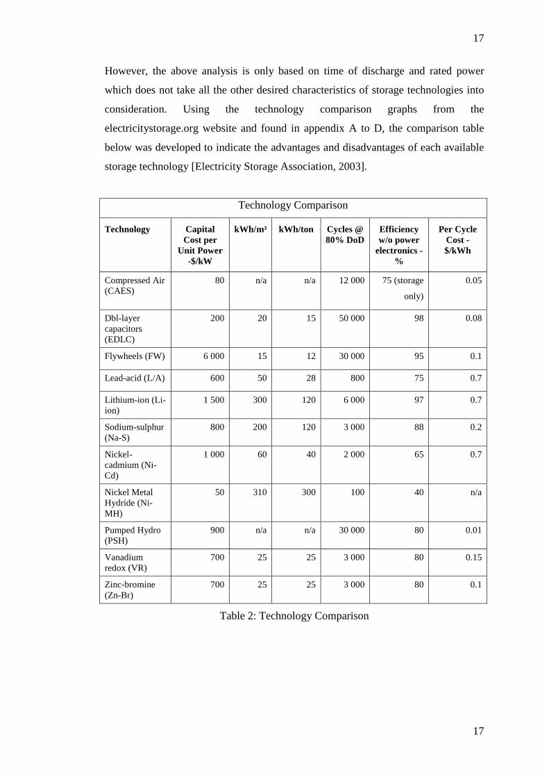
However, the above analysis is only based on time of discharge and rated power
which does not take all the other desired characteristics of storage technologies into
consideration. Using the technology comparison graphs from the
electricitystorage.org website and found in appendix A to D, the comparison table
below was developed to indicate the advantages and disadvantages of each available
storage technology [Electricity Storage Association, 2003].
Technology Comparison
Technology Capital Cost per
Unit Power -$/kW
kWh/m³ kWh/ton Cycles @ 80% DoD
Efficiency w/o power
electronics - %
Per Cycle Cost - $/kWh
Compressed Air (CAES)
80 n/a n/a 12 000 75 (storage
only)
0.05
Dbl-layer capacitors (EDLC)
200 20 15 50 000 98 0.08
Flywheels (FW) 6 000 15 12 30 000 95 0.1
Lead-acid (L/A) 600 50 28 800 75 0.7
Lithium-ion (Li-ion)
1 500 300 120 6 000 97 0.7
Sodium-sulphur (Na-S)
800 200 120 3 000 88 0.2
Nickel-cadmium (Ni-Cd)
1 000 60 40 2 000 65 0.7
Nickel Metal Hydride (Ni-MH)
50 310 300 100 40 n/a
Pumped Hydro (PSH)
900 n/a n/a 30 000 80 0.01
Vanadium redox (VR)
700 25 25 3 000 80 0.15
Zinc-bromine (Zn-Br)
700 25 25 3 000 80 0.1
Table 2: Technology Comparison
18
18
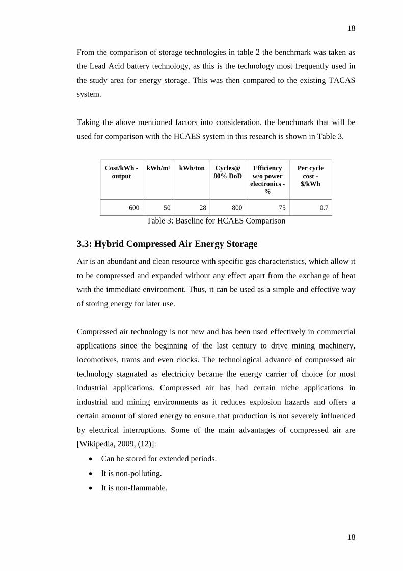
From the comparison of storage technologies in table 2 the benchmark was taken as
the Lead Acid battery technology, as this is the technology most frequently used in
the study area for energy storage. This was then compared to the existing TACAS
system.
Taking the above mentioned factors into consideration, the benchmark that will be
used for comparison with the HCAES system in this research is shown in Table 3.
Cost/kWh - output
kWh/m³ kWh/ton Cycles@ 80% DoD
Efficiency w/o power
electronics - %
Per cycle cost -
$/kWh
600 50 28 800 75 0.7
Table 3: Baseline for HCAES Comparison
3.3: Hybrid Compressed Air Energy Storage
Air is an abundant and clean resource with specific gas characteristics, which allow it
to be compressed and expanded without any effect apart from the exchange of heat
with the immediate environment. Thus, it can be used as a simple and effective way
of storing energy for later use.
Compressed air technology is not new and has been used effectively in commercial
applications since the beginning of the last century to drive mining machinery,
locomotives, trams and even clocks. The technological advance of compressed air
technology stagnated as electricity became the energy carrier of choice for most
industrial applications. Compressed air has had certain niche applications in
industrial and mining environments as it reduces explosion hazards and offers a
certain amount of stored energy to ensure that production is not severely influenced
by electrical interruptions. Some of the main advantages of compressed air are
[Wikipedia, 2009, (12)]:
• Can be stored for extended periods.
• It is non-polluting.
• It is non-flammable.
19
19
• It is non-toxic.
• Most compressed air equipment is recyclable.
• Compressed air systems have a high cyclic life time.
• Air motors are simple, robust and deliver a high torque.
As with chemical batteries and hydrogen storage, the main disatvantage of
compressed air is the indirect use of energy. Energy is required to first compress the
air, after which decompressing the air releases the energy to drive air equipment such
as air motors. The conversion between different energy carriers will result in losses,
which will reduce the overall efficiency of such a system. Additional disadvantages
are [Wikipedia, 2009, (12)]:
• When air is compressed it heats up, and heat energy is lost to surroundings.
• When compressed air is decompressed it cools down, reducing its working
pressure.
• Moisture and particles in the air could effect or damage the equipment due to
the high working pressures required.
• Not all the compressed air in the storage device can be utilised to do work.
Air can be compressed and stored using three different processes [Wikipedia, 2009
(13)]:
1. The first option is to perform the compression and storage of the air
adiabatically, which implies that the heat that is generated during
compression is also stored and then added back during decompression.
Theoretically, an adiabatic process can be 100% efficient, but in practice
cycle efficiencies close to 70% can be expected.
2. The second option is a diabatic process, where intercoollers between
compression stages are used to dissapate heat to the atmosphere. Then, during
decompression, the air is reheated by either adding fuel and igniting the air or
by using heated metal mass. The highest efficiency achieved by a commercial
installation is 54%.
20
20
3. The final option is to employ an isothermal process for compressing and
expanding air. Once again efficiencies close to 100% can theoretically be
achieved. In the isothermal process very effective heat exchangers are needed
due to the fact that a constant heat exchange with the environment is required
during compression and expansion. Currently this process is only used for
low power applications as slow cycling is required to maximise heat
exchange.
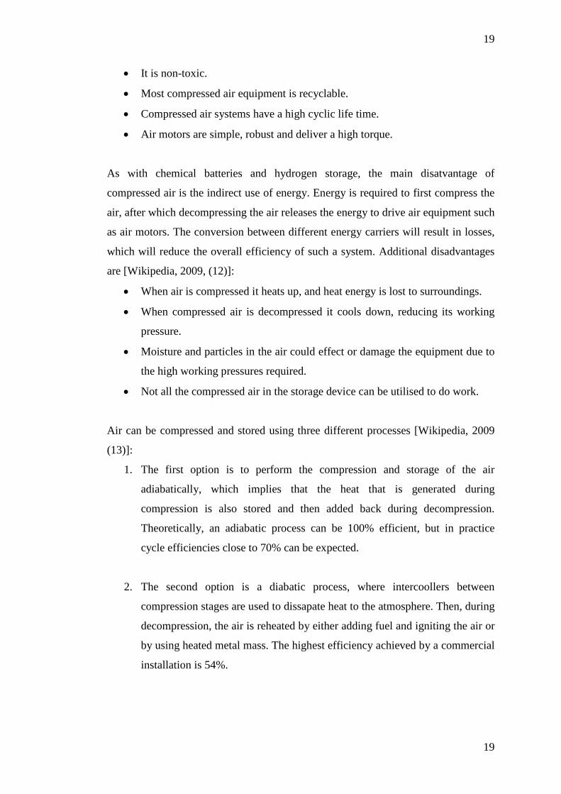
During research for this study, the only two commercial systems for small to medium
scale energy storage applications that could be found, were the TACAS
uninterrupted power supply system and the MDI stand-by generator. After initiating
contact in an attempt to establish the cost and performance of both, only Active
Power responded with the price of $110 000 US for their 85 kW/15min system.
Table 4: Energy Storage Technologies Compared [J.R Sears, 18].
The TACAS system incorporates three different technologies in order to offer an
environmentally friendly uninterrupted power supply. It combines air storage with
thermal storage and a flywheel in order to firstly improve the efficiency of the air
decompression during power delivery and, secondly, to ensure quality of supply or
21
21
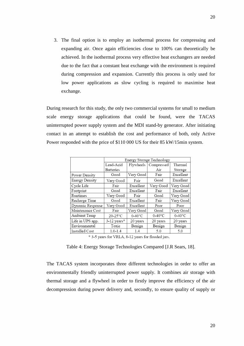
bridging power. The air storage tanks operate at 31 MPa or 310 bar pressure and are
based on the self-contained breathing apparatus (SCBA) tanks used by divers and
fire fighters. The thermal storage unit consists of a stainless steel core with internal
passages to transfer heat to the air being decompressed, which is kept at 977 K by
normal electric resistance heaters. The flywheel is a new design that will supply the
full back-up load for three seconds (85 kJ x 3s = 255 kJ, if taking 85 kW for 15
minutes) [J.R Sears, 18].
Figure 9: Thermal and Compressed-Air Storage (TACAS) Diagram [J.R Sears, p3,
18].
The paper by John Sears indicated an exit air flow of 700 cubic feet of free air or 21
m³ from the expansion turbine used in the TACAS system for an output supplying a
load of 84 kW for 15 minutes. The turbine therefore supplied 76 MJ of energy or 21
kW of power to the load in those 15 minutes [J.R Sears, 18]. Compared to this, the
Ingersoll Rand air motor, KK6M is an 18.64 kW motor which requires 19 m³ of air
per minute, and would have supplied only 16.776 MJ in 15 minutes [Ingersoll Rand,
p71, 19]. Based on this analysis the TACAS system can produce 4 times more power
than the commercial KK6M air motor with only an additional 2 m³ of air per minute,
not taking into account the compressor, air storage and thermal storage losses. If
these losses are taken into consideration it must be assumed that the overall system
efficiency would be much less than the 40.7 % estimated by Bossel for this type of
system, as just the energy lost to keep the thermal system at 977 °K would
22
22
significantly increase per cycle cost and at the same time bring efficiency down by a
large margin.
The air storage requirement for the TACAS system is 21 m³ x 15 = 315 m³.
Assuming that the air is stored at 310 bar pressure the tank size will be (315 m³ x
101.3 kPa) / 31 000 kPa = 1.029 m³, with a weight of 361 kg if the weight of free air
is taken as 1.205 kg/m³ at 20 °C.
23
23
Cost/kWh -
output kWh/m³ kWh/ton Cycles @
80% DoD Efficiency w/o power
electronics - %
Per Cycle Cost - $/kWh
Baseline 600 50 28 800 75 0.7
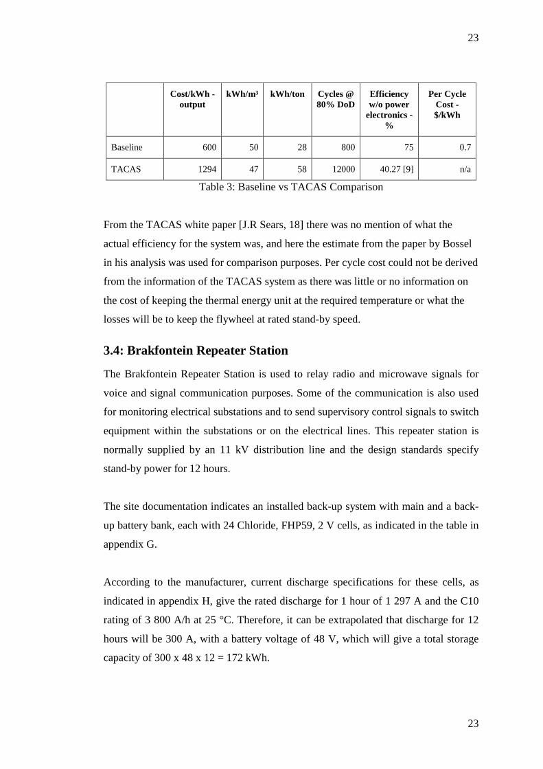
TACAS 1294 47 58 12000 40.27 [9] n/a
Table 3: Baseline vs TACAS Comparison
From the TACAS white paper [J.R Sears, 18] there was no mention of what the
actual efficiency for the system was, and here the estimate from the paper by Bossel
in his analysis was used for comparison purposes. Per cycle cost could not be derived
from the information of the TACAS system as there was little or no information on
the cost of keeping the thermal energy unit at the required temperature or what the
losses will be to keep the flywheel at rated stand-by speed.
3.4: Brakfontein Repeater Station
The Brakfontein Repeater Station is used to relay radio and microwave signals for
voice and signal communication purposes. Some of the communication is also used
for monitoring electrical substations and to send supervisory control signals to switch
equipment within the substations or on the electrical lines. This repeater station is
normally supplied by an 11 kV distribution line and the design standards specify
stand-by power for 12 hours.
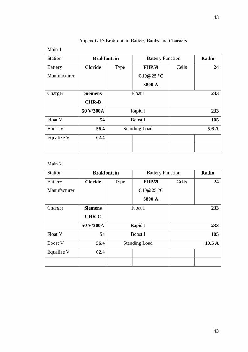
The site documentation indicates an installed back-up system with main and a back-
up battery bank, each with 24 Chloride, FHP59, 2 V cells, as indicated in the table in
appendix G.
According to the manufacturer, current discharge specifications for these cells, as
indicated in appendix H, give the rated discharge for 1 hour of 1 297 A and the C10
rating of 3 800 A/h at 25 °C. Therefore, it can be extrapolated that discharge for 12
hours will be 300 A, with a battery voltage of 48 V, which will give a total storage
capacity of 300 x 48 x 12 = 172 kWh.
24
24
3.5: Selected HCAES Equipment for Design
Following the literature and internet research and subsequent to the evaluation of the
existing material on HCAES systems, the various alternatives were investigated to
find all the available equipment that could be used in an off the shelf design. Based
on the TACAS research, the air storage pressure needed to be at least 30 MPa or
more, with an air motor that can supply an alternator of at least 15 kW, after losses,
in order to supply the stand-by load of the repeater station. The air storage for 12
hours will depend on the efficiency and the free air usage of the air motor.
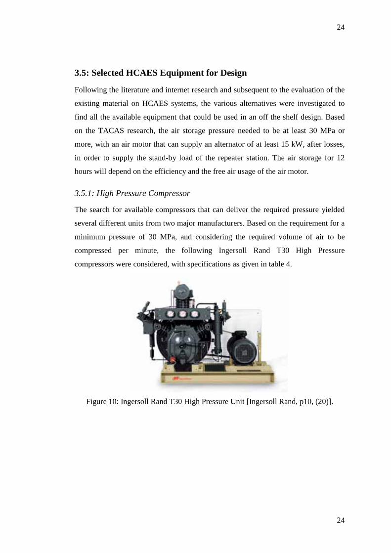
3.5.1: High Pressure Compressor
The search for available compressors that can deliver the required pressure yielded
several different units from two major manufacturers. Based on the requirement for a
minimum pressure of 30 MPa, and considering the required volume of air to be
compressed per minute, the following Ingersoll Rand T30 High Pressure
compressors were considered, with specifications as given in table 4.
Figure 10: Ingersoll Rand T30 High Pressure Unit [Ingersoll Rand, p10, (20)].
25
25
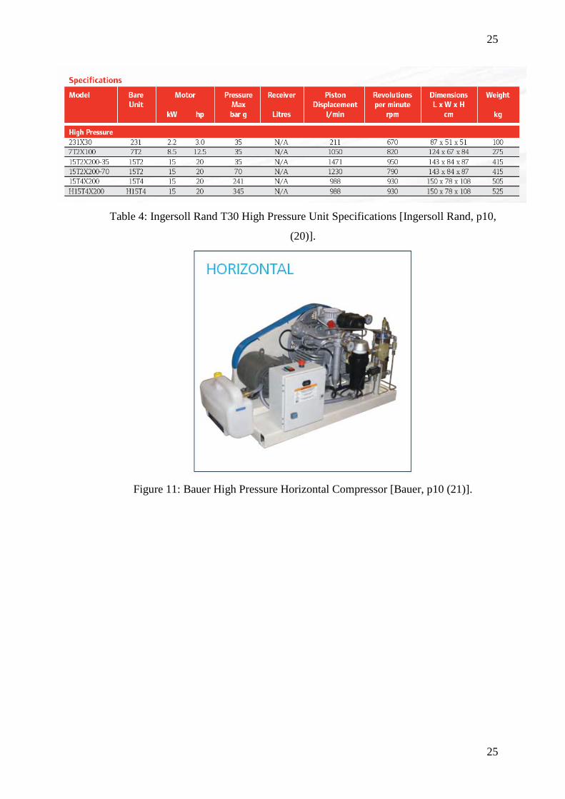
Table 4: Ingersoll Rand T30 High Pressure Unit Specifications [Ingersoll Rand, p10,
(20)].
Figure 11: Bauer High Pressure Horizontal Compressor [Bauer, p10 (21)].
26
26
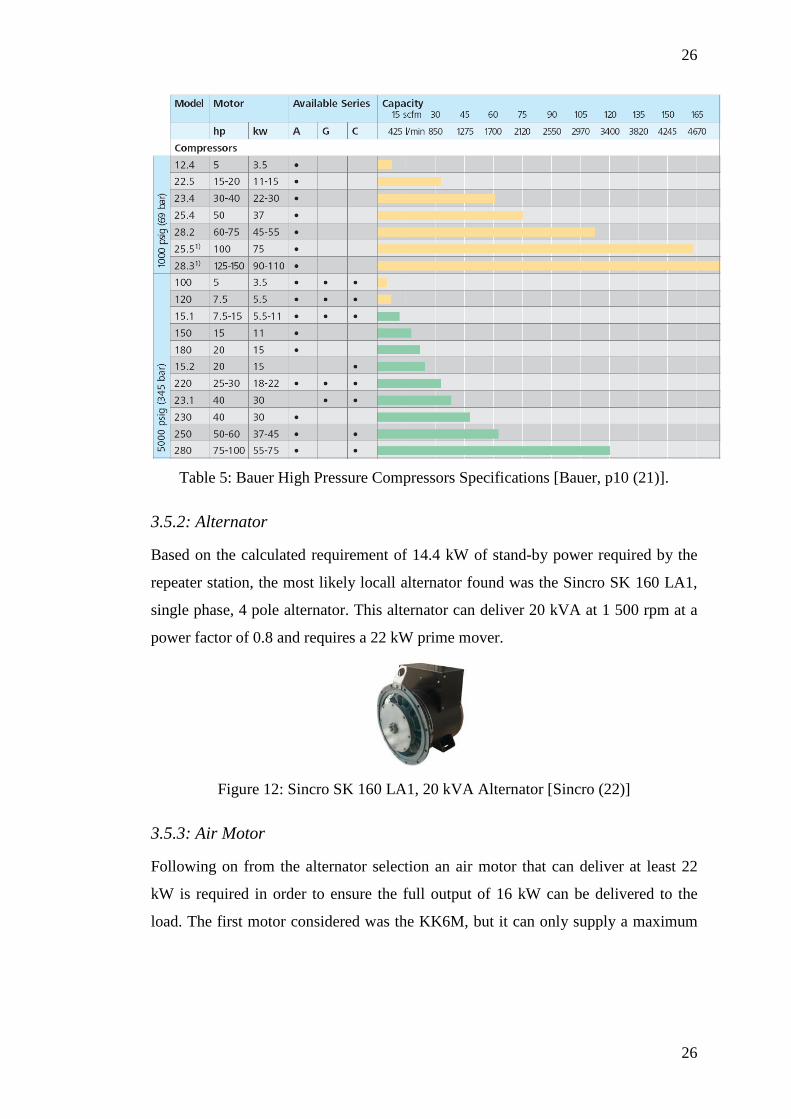
Table 5: Bauer High Pressure Compressors Specifications [Bauer, p10 (21)].
3.5.2: Alternator
Based on the calculated requirement of 14.4 kW of stand-by power required by the
repeater station, the most likely locall alternator found was the Sincro SK 160 LA1,
single phase, 4 pole alternator. This alternator can deliver 20 kVA at 1 500 rpm at a
power factor of 0.8 and requires a 22 kW prime mover.
Figure 12: Sincro SK 160 LA1, 20 kVA Alternator [Sincro (22)]
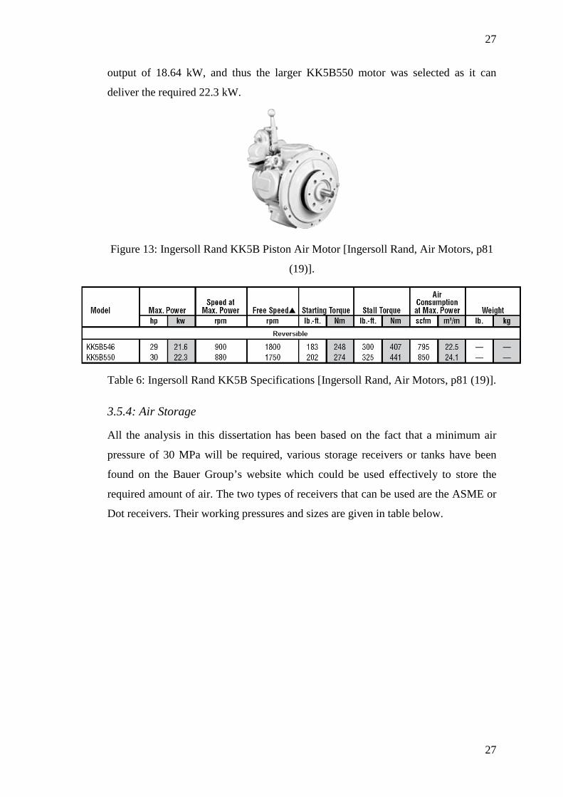
3.5.3: Air Motor
Following on from the alternator selection an air motor that can deliver at least 22
kW is required in order to ensure the full output of 16 kW can be delivered to the
load. The first motor considered was the KK6M, but it can only supply a maximum
27
27
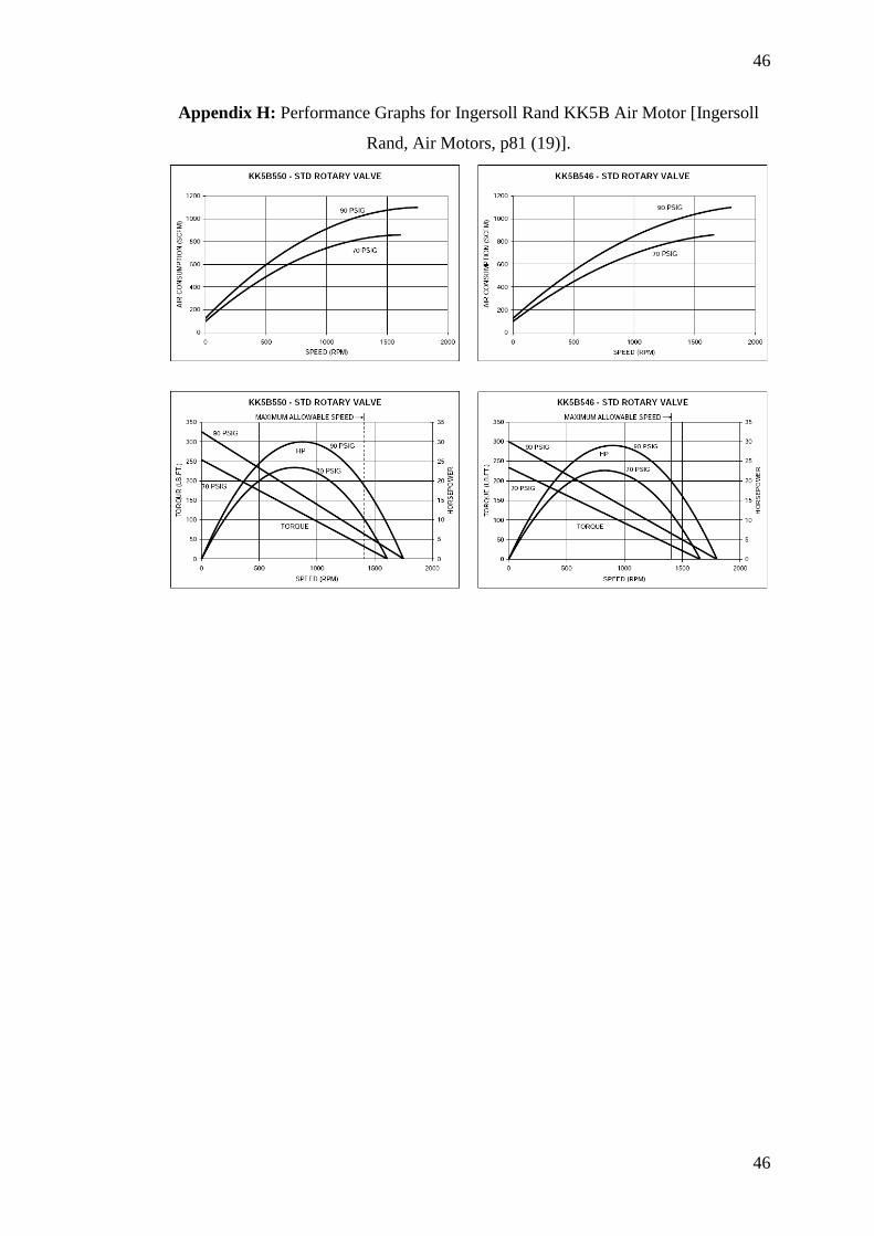
output of 18.64 kW, and thus the larger KK5B550 motor was selected as it can
deliver the required 22.3 kW.
Figure 13: Ingersoll Rand KK5B Piston Air Motor [Ingersoll Rand, Air Motors, p81
(19)].
Table 6: Ingersoll Rand KK5B Specifications [Ingersoll Rand, Air Motors, p81 (19)].
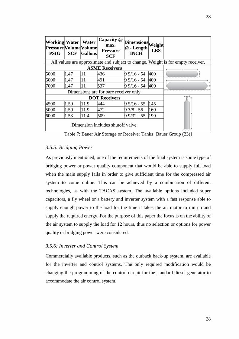
3.5.4: Air Storage
All the analysis in this dissertation has been based on the fact that a minimum air
pressure of 30 MPa will be required, various storage receivers or tanks have been
found on the Bauer Group’s website which could be used effectively to store the
required amount of air. The two types of receivers that can be used are the ASME or
Dot receivers. Their working pressures and sizes are given in table below.
28
28
Working Pressure
PSIG
Water Volume
SCF
Water Volume Gallons
Capacity @ max.
Pressure SCF
Dimensions Ø - Length
INCH
Weight LBS
All values are approximate and subject to change. Weight is for empty receiver. ASME Receivers
5000 1.47 11 436 9 9/16 - 54 400 6000 1.47 11 491 9 9/16 - 54 400 7000 1.47 11 537 9 9/16 - 54 400
Dimensions are for bare receiver only. DOT Receivers
4500 1.59 11.9 444 9 5/16 - 55 145 5000 1.59 11.9 472 9 3/8 - 56 160 6000 1.53 11.4 509 9 9/32 - 55 190
Dimension includes shutoff valve.
Table 7: Bauer Air Storage or Receiver Tanks [Bauer Group (23)]
3.5.5: Bridging Power
As previously mentioned, one of the requirements of the final system is some type of
bridging power or power quality component that would be able to supply full load
when the main supply fails in order to give sufficient time for the compressed air
system to come online. This can be achieved by a combination of different
technologies, as with the TACAS system. The available options included super
capacitors, a fly wheel or a battery and inverter system with a fast response able to
supply enough power to the load for the time it takes the air motor to run up and
supply the required energy. For the purpose of this paper the focus is on the ability of
the air system to supply the load for 12 hours, thus no selection or options for power
quality or bridging power were considered.
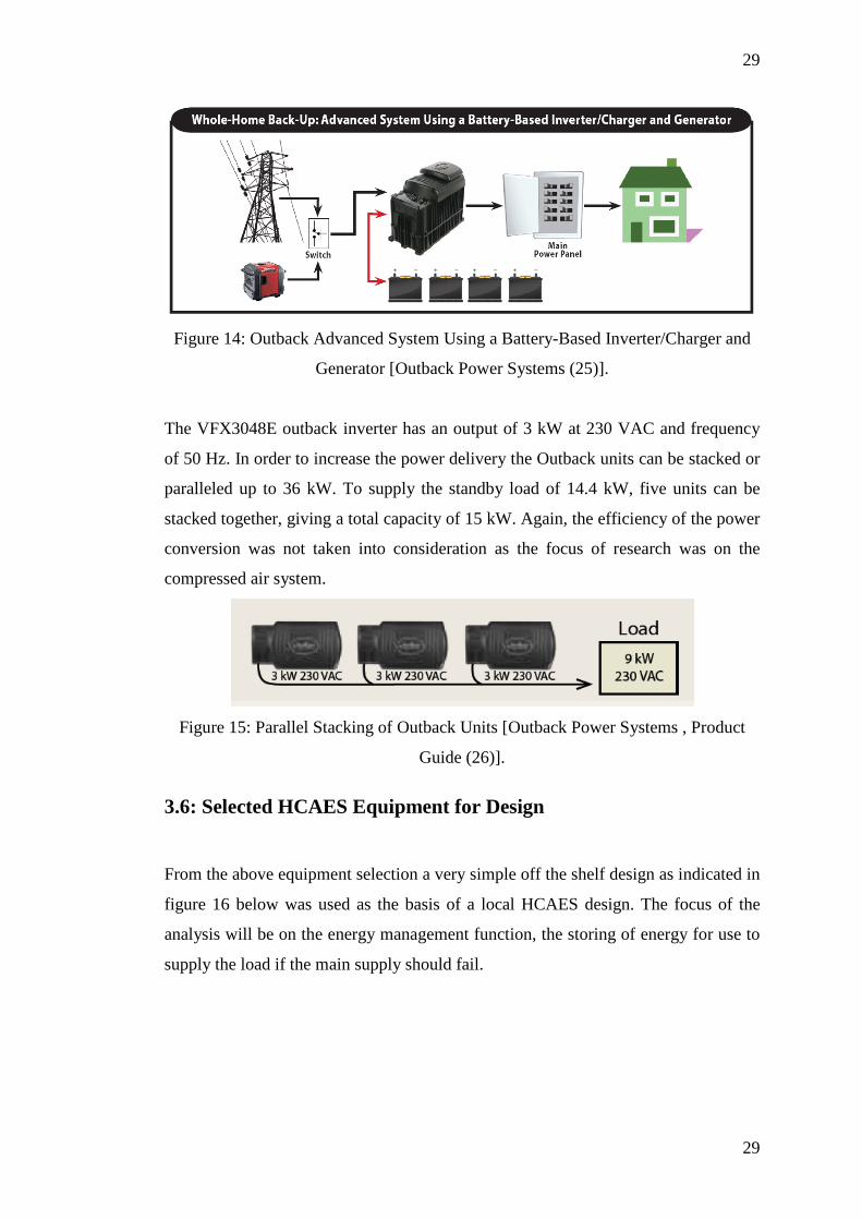
3.5.6: Inverter and Control System
Commercially available products, such as the outback back-up system, are available
for the inverter and control systems. The only required modification would be
changing the programming of the control circuit for the standard diesel generator to
accommodate the air control system.
29
29
Figure 14: Outback Advanced System Using a Battery-Based Inverter/Charger and
Generator [Outback Power Systems (25)].
The VFX3048E outback inverter has an output of 3 kW at 230 VAC and frequency
of 50 Hz. In order to increase the power delivery the Outback units can be stacked or
paralleled up to 36 kW. To supply the standby load of 14.4 kW, five units can be
stacked together, giving a total capacity of 15 kW. Again, the efficiency of the power
conversion was not taken into consideration as the focus of research was on the
compressed air system.
Figure 15: Parallel Stacking of Outback Units [Outback Power Systems , Product
Guide (26)].
3.6: Selected HCAES Equipment for Design
From the above equipment selection a very simple off the shelf design as indicated in
figure 16 below was used as the basis of a local HCAES design. The focus of the
analysis will be on the energy management function, the storing of energy for use to
supply the load if the main supply should fail.
30
30
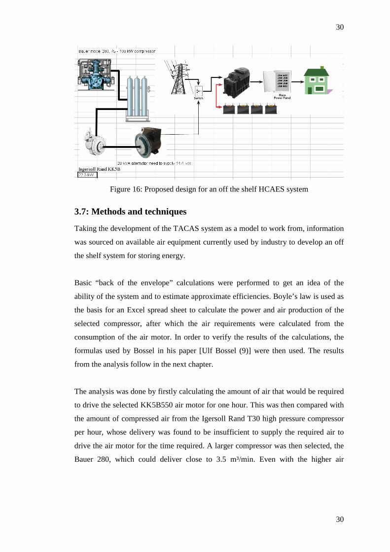
Figure 16: Proposed design for an off the shelf HCAES system
3.7: Methods and techniques
Taking the development of the TACAS system as a model to work from, information
was sourced on available air equipment currently used by industry to develop an off
the shelf system for storing energy.
Basic “back of the envelope” calculations were performed to get an idea of the
ability of the system and to estimate approximate efficiencies. Boyle’s law is used as
the basis for an Excel spread sheet to calculate the power and air production of the
selected compressor, after which the air requirements were calculated from the
consumption of the air motor. In order to verify the results of the calculations, the
formulas used by Bossel in his paper [Ulf Bossel (9)] were then used. The results
from the analysis follow in the next chapter.
The analysis was done by firstly calculating the amount of air that would be required
to drive the selected KK5B550 air motor for one hour. This was then compared with
the amount of compressed air from the Igersoll Rand T30 high pressure compressor
per hour, whose delivery was found to be insufficient to supply the required air to
drive the air motor for the time required. A larger compressor was then selected, the
Bauer 280, which could deliver close to 3.5 m³/min. Even with the higher air
31
31
delivery it was not enough to run the air motor for the expected time, after which the
efficiency of the air motor was scrutinised by comparing the energy in and the
energy out. The analysis of the motor efficiency gave a strong indication that the
motor was not designed for efficiency, but more for performance.
32
32
CHAPTER 4
RESULTS FROM ANALYSIS OF PROPOSED DESIGN
4.1: Introduction
A spreadsheet was used to first calculate the amount of air that can be stored by the
Bauer, model 280, 75 - 100 kW compressor and then this was compared to the air
supply requirements of the Ingersoll Rand KK5B550, 22.3 kW air motor in order to
deliver the required power to the Syncro 16 kW alternator. Boyle’s law was used to
calculate the air delivery of the compressor, and reverse calculations were used to
derive the air storage requirements of the air motor. The results of these calculations
were found to be completely unacceptable when taking the 75% efficiency from the
derived base case into consideration. In order to test the results, the quantity of stored
energy within the compressed air and the amount of air used by the motor were
compared. The result of this comparison gave a very strong indication of the
efficiency of such a off the shelf compressed air system, not taking into account the
losses of the components that would need to supply the bridging power or power
electronics.
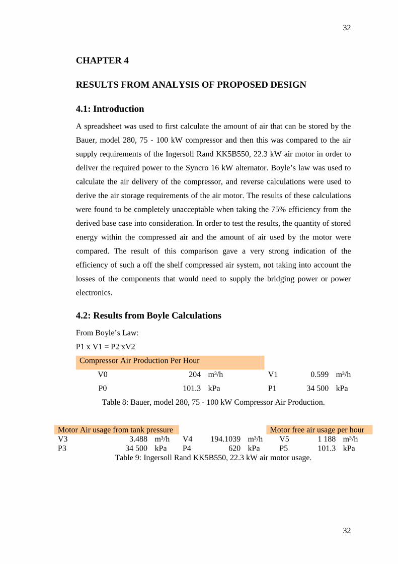
4.2: Results from Boyle Calculations
From Boyle’s Law:
P1 x V1 = P2 xV2
Compressor Air Production Per Hour
V0 204 m³/h V1 0.599 m³/h
P0 101.3 kPa P1 34 500 kPa
Table 8: Bauer, model 280, 75 - 100 kW Compressor Air Production.
Motor Air usage from tank pressure Motor free air usage per hour V3 3.488 m³/h V4 194.1039 m³/h V5 1 188 m³/h P3 34 500 kPa P4 620 kPa P5 101.3 kPa
Table 9: Ingersoll Rand KK5B550, 22.3 kW air motor usage.
33
33
In calculating the air motor air usage it was assumed that the outlet air will be at
ambient pressure of 101.3 kPa. The large discrepancy between the air delivered to
the air receiver by the compressor driven by a 100 kW motor, and the air required by
the air motor to deliver 22.3 kW of power showed such a large discrepancy that a
additional method was needed to calculate the amount of energy stored by the
compressor an hour, and the amount of stored energy actually consumed by the
motor in an hour.
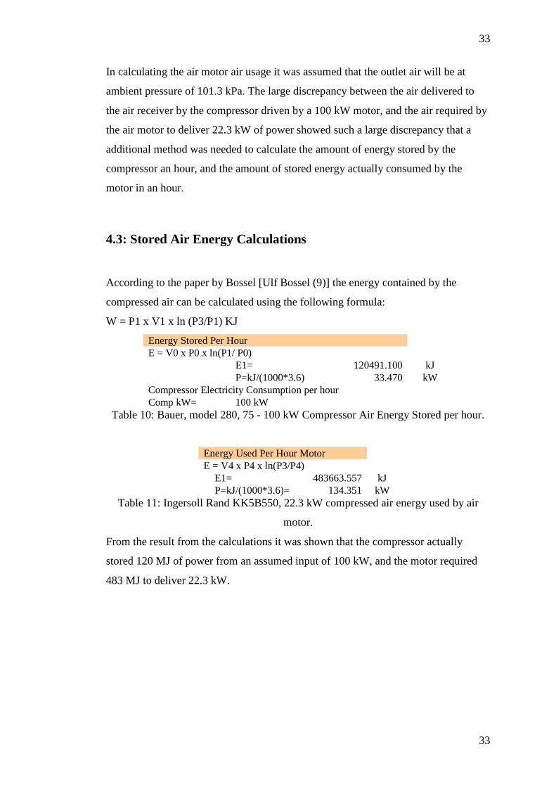
4.3: Stored Air Energy Calculations
According to the paper by Bossel [Ulf Bossel (9)] the energy contained by the
compressed air can be calculated using the following formula:
W = P1 x V1 x ln (P3/P1) KJ
Energy Stored Per Hour E = V0 x P0 x ln(P1/ P0) E1= 120491.100 kJ P=kJ/(1000*3.6) 33.470 kW Compressor Electricity Consumption per hour Comp kW= 100 kW
Table 10: Bauer, model 280, 75 - 100 kW Compressor Air Energy Stored per hour.
Energy Used Per Hour Motor E = V4 x P4 x ln(P3/P4) E1= 483663.557 kJ P=kJ/(1000*3.6)= 134.351 kW
Table 11: Ingersoll Rand KK5B550, 22.3 kW compressed air energy used by air
motor.
From the result from the calculations it was shown that the compressor actually
stored 120 MJ of power from an assumed input of 100 kW, and the motor required
483 MJ to deliver 22.3 kW.
34
34
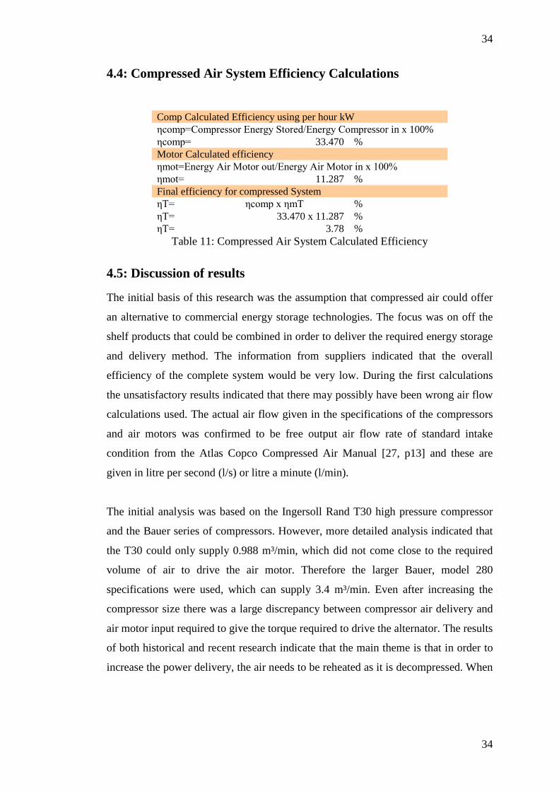
4.4: Compressed Air System Efficiency Calculations
Comp Calculated Efficiency using per hour kW ηcomp=Compressor Energy Stored/Energy Compressor in x 100% ηcomp= 33.470 % Motor Calculated efficiency ηmot=Energy Air Motor out/Energy Air Motor in x 100% ηmot= 11.287 % Final efficiency for compressed System ηT= ηcomp x ηmT % ηT= 33.470 x 11.287 % ηT= 3.78 %
Table 11: Compressed Air System Calculated Efficiency
4.5: Discussion of results
The initial basis of this research was the assumption that compressed air could offer
an alternative to commercial energy storage technologies. The focus was on off the
shelf products that could be combined in order to deliver the required energy storage
and delivery method. The information from suppliers indicated that the overall
efficiency of the complete system would be very low. During the first calculations
the unsatisfactory results indicated that there may possibly have been wrong air flow
calculations used. The actual air flow given in the specifications of the compressors
and air motors was confirmed to be free output air flow rate of standard intake
condition from the Atlas Copco Compressed Air Manual [27, p13] and these are
given in litre per second (l/s) or litre a minute (l/min).
The initial analysis was based on the Ingersoll Rand T30 high pressure compressor
and the Bauer series of compressors. However, more detailed analysis indicated that
the T30 could only supply 0.988 m³/min, which did not come close to the required
volume of air to drive the air motor. Therefore the larger Bauer, model 280
specifications were used, which can supply 3.4 m³/min. Even after increasing the
compressor size there was a large discrepancy between compressor air delivery and
air motor input required to give the torque required to drive the alternator. The results
of both historical and recent research indicate that the main theme is that in order to
increase the power delivery, the air needs to be reheated as it is decompressed. When
35
35
this is done in stages it significantly increases the efficiency of the system. In the
analysis presented here no reheating was considered as the actual performance of the
unmodified, commercially available, air equipment needed to be evaluated.
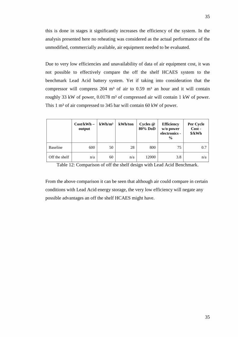
Due to very low efficiencies and unavailability of data of air equipment cost, it was
not possible to effectively compare the off the shelf HCAES system to the
benchmark Lead Acid battery system. Yet if taking into consideration that the
compressor will compress 204 m³ of air to 0.59 m³ an hour and it will contain
roughly 33 kW of power, 0.0178 m³ of compressed air will contain 1 kW of power.
This 1 m³ of air compressed to 345 bar will contain 60 kW of power.
Cost/kWh – output
kWh/m³ kWh/ton Cycles @ 80% DoD
Efficiency w/o power
electronics - %
Per Cycle Cost - $/kWh
Baseline 600 50 28 800 75 0.7
Off the shelf n/a 60 n/a 12000 3.8 n/a
Table 12: Comparison of off the shelf design with Lead Acid Benchmark.
From the above comparison it can be seen that although air could compare in certain
conditions with Lead Acid energy storage, the very low efficiency will negate any
possible advantages an off the shelf HCAES might have.
36
36
CHAPTER 5
DISCUSSION
5.1: Introduction
The work done during the research revolved around answering the main research
question from available literature, i.e., if HCAES could offer a viable alternative
solution to energy storage requirements of small to medium size renewable energy
systems. Due to the nature of study, no laboratory work could be performed to test
the answers found during the study or to prove the results from calculations. In spite
of this there is a strong indication that the results for the proposed design may be
correct, based on the information that can be found in the information given in the
specification sheets of the Bauer, model 280 [Bauer Group (23)] compressor and the
Ingersoll Rand KK5B550 [Ingersoll Rand (19)] air motor. This is based on the
comparison of the free output air rate per minute.
5.2: Discussion
The air equipment that was considered in this dissertation is currently being utilised
in industrial applications where the specific characteristics offer a benefit to various
production processes. The equipment under consideration was never designed or
intended to be used in a power storage and delivery system as would be required by a
communication repeater station. The fact that the compressed air system is storing
energy cannot be disputed, but there does not seem to have been any great motivation
to increase equipment efficiencies due to the nature of the standard applications,
where energy efficiencies are not important. This may change as energy becomes a
scarce and expensive commodity.
The initial assumption was that increasing the pressure of the stored air, more air can
be stored in smaller vessels, which of course is correct. However, this increases the
losses considerably. This is due to the fact that as the pressure of air is increased and
its volume is reduced heat is being produced that will be passed to atmosphere. This
is a direct loss of energy which decreases the energy contained within the air that is
37
37
being stored. In addition, the air entering the storage tank will be at temperatures
ranging from 40 to 80 °C, depending on compressor cooling and will then cool down
to ambient temperature over time, further decreasing the energy content of the stored
air. This was not considered as the initial calculations gave a strong enough
indication of the overall effectiveness and efficiency of the air system.
The process that is being used by the compressor is a diabatic process, involving
cooling between stages to dissipate the heat to the atmosphere. The Bauer, model 280
compressor has a four stage inter-cooling system and the final temperature of air
leaving the compressor could not be found from manufacturer specification sheets.
Based on calculations, the efficiency of the compressor was calculated to be 33.47%
to compress air to 345 bar pressure, delivering 204 m³/h of free air. This is based on
the assumption that the required input power would be 100 kW to drive the
compressor.
The Ingersoll Rand KK5B550 air motor uses an isothermal process, exchanging
constant heat with the environment during expansion of air through the motor.
Theoretically, 100% efficiencies could be achieved when very effective heat
exchangers are used and the air is expanded slowly in order to maximise heat
transfer. However, the KK5B550 air motor does not seem to have effective heat
exchange properties and this can be clearly seen based on the amount of air required
in order to deliver 22.3 kW of power to the alternator. The amount of air from an
efficient motor using the isothermal process that would deliver 22.3 kW can be
calculated as:
Energy Required, Q = kW x 3.6 MJ
Energy Required, Q = 22.3 x 3.6 MJ
Energy Required, Q = 80.28 MJ
Air required to deliver 22.3 kW = V1
Q = P1 x V1 x ln (P3/P1) kJ
80280 = 101.3 x V1 x ln (34500/101.3) kJ
38
38
V1 = 80280/(101.3 x 5.83)
V1 = 135.9 m³
The previous calculation clearly indicates that the 204 m³/h of free air delivered by
the compressor should be more than enough to drive an efficient air motor, yet the
KK5B550 air motor requires 1 188 m³/h of free air - almost eight times as much air
as predicted by the ideal calculations. Based on the reported results of the TACAS
system, which incorporates inter-heating, modifying the KK5B550 air motor with
inter-heating could reduce the air consumption to 297 m³/h. The calculated efficiency
of the air system without modification was 3.7%. This means that the compressor is
required to deliver 1 188 m³/h, using an assumed 100 kW while needing to run for
5.7 hours to produce enough air to supply the air motor for one hour. The power
consumption for the compressor would be 579 kW to supply the required air the air-
motor will need to deliver 22.3 kW for one hour. The resultant overall efficiency of
3.7 % is not suitable for any form of energy storage application. The foregoing
analysis does not even include the losses that would be associated with the power
electronics or the bridging power component.
The low efficiencies as described above show why all the current research and new
commercial applications are focussed on new, innovative and efficient designs and/or
modification required for air motors, combined with other technologies such as
super-capacitors, thermal heat storage and flywheels. Both the TACAS [4] and MDI
literature mention this requirement in order to improve the efficiencies of a HCAES
system. If a HCAES system using the identified off the shelf air equipment would
have been used to supply the standby power for the selected application the input
power required would have been 579 x 12 = 6 828 kW for a storage capacity of 172
kWh. Comparing this to the lead acid battery that is currently used with an efficiency
of 75%, it is clear that a HCAES system using off the shelf equipment without
modification and combining it with other technologies cannot be considered as an
alternative solution to conventional chemical battery storage system.
39
39
CHAPTER 6
CONCLUSIONS
6.1: Conclusions
In this dissertation, it was shown that compressed air has been used for more than a
century for applications ranging from drills to locomotives and power tools.
Compressed air technology has been receiving renewed interest based on the twin
imperatives of fossil fuel scarcity and the drive for renewable energy sources. This
research evaluated HCAES technology in order to find out if it could offer a viable
alternative energy storage solution for small to medium scale renewable energy
systems.
Using the existing energy storage technologies as a baseline to compare new HCAES
technology such as the TACAS system it was clearly shown with the available
information that, besides a high life cycle and environmental advantages, the TACAS
system does not seem to be an effective alternative to existing energy storage
technologies. The off the shelf design without any modification to include inter-
heating stages in the decompression stage and with a calculated efficiency of 3.8%
will have very high per cycle cost and will not be a viable alternative to conventional
battery storage.
It must be mentioned that with further research it would be possible to increase
efficiencies of HCAES systems closer to the ideal. Research is improving
compression and decompression using more effective isothermal processes, with
much more efficient heat transfer materials, and adding intermediate air receivers
between pressures which will increase the tank time helping more effective heat
transfer to take place.
40
40
6.2: Recommendations
Initially, the information contained in this document was obtained from suppliers.
However, the information provided did not completely match the information
required to perform detailed analysis. It would also be advantageous to perform
laboratory measurements to confirm the quoted results and to test the efficiency of
the complete system.
Further research that could possibly help making the HCAES technology more viable
and that could increase efficiencies of current air equipment include, but is not
limited to the following:
• Efficiant heat exchangers for compression and expansion stage to facilitate
easier exchange of heat with environment.
• Compressed air motors with inter-heating between stages.
• Split compressors with intermediate settling or heat exchange tank for higher
pressures.
• Air-oil or air-water hybrid CAES system.
• Solar heating for heating thermal storage unit in expansion stage.
• Highly insulated thermal storage unit with low heat exchange properties.

41
41
APPENDICES
Appendix A: Capital Cost of Energy Storage Systems
http://electricitystorage.org/tech/technologies_comparisons_capitalcost.htm)
Appendix B: Size and Weight of Energy Storage Systems
http://electricitystorage.org/tech/technologies_comparisons_sizeweight.htm)
42
42
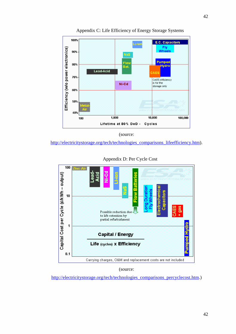
Appendix C: Life Efficiency of Energy Storage Systems
(source:
http://electricitystorage.org/tech/technologies_comparisons_lifeefficiency.htm).
Appendix D: Per Cycle Cost
(source:
http://electricitystorage.org/tech/technologies_comparisons_percyclecost.htm.)
43
43
Appendix E: Brakfontein Battery Banks and Chargers
Main 1
Station Brakfontein Battery Function Radio
Battery
Manufacturer
Cloride Type FHP59
C10@25 °C
3800 A
Cells 24
Charger Siemens
CHR-B
Float I 233
50 V/300A Rapid I 233
Float V 54 Boost I 105
Boost V 56.4 Standing Load 5.6 A
Equalize V 62.4
Main 2
Station Brakfontein Battery Function Radio
Battery
Manufacturer
Cloride Type FHP59
C10@25 °C
3800 A
Cells 24
Charger Siemens
CHR-C
Float I 233
50 V/300A Rapid I 233
Float V 54 Boost I 105
Boost V 56.4 Standing Load 10.5 A
Equalize V 62.4
44
44
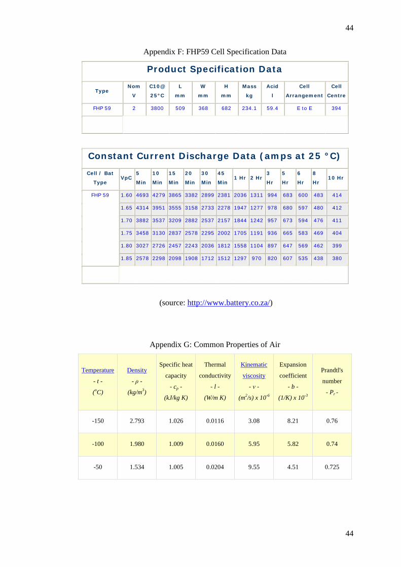
Appendix F: FHP59 Cell Specification Data
Product Specification Data
Type Nom
V C10@
25°C L
mm W
mm H
mm Mass
kg Acid
l Cell
Arrangement Cell
Centre FHP 59 2 3800 509 368 682 234.1 59.4 E to E 394
Constant Current Discharge Data (amps at 25 °C)
Cell / Bat
Type VpC 5
Min 10
Min 15
Min 20
Min 30
Min 45
Min 1 Hr 2 Hr 3
Hr 5
Hr 6
Hr 8
Hr 10 Hr
FHP 59 1.60 4693 4279 3865 3382 2899 2381 2036 1311 994 683 600 483 414 1.65 4314 3951 3555 3158 2733 2278 1947 1277 978 680 597 480 412 1.70 3882 3537 3209 2882 2537 2157 1844 1242 957 673 594 476 411 1.75 3458 3130 2837 2578 2295 2002 1705 1191 936 665 583 469 404 1.80 3027 2726 2457 2243 2036 1812 1558 1104 897 647 569 462 399 1.85 2578 2298 2098 1908 1712 1512 1297 970 820 607 535 438 380
(source: http://www.battery.co.za/)
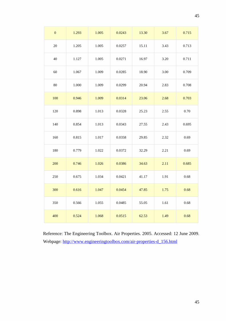
Appendix G: Common Properties of Air
Temperature
- t -
(oC)
Density
- ρ -
(kg/m3)
Specific heat
capacity
- cp -
(kJ/kg K)
Thermal
conductivity
- l -
(W/m K)
Kinematic
viscosity
- ν -
(m2/s) x 10-6
Expansion
coefficient
- b -
(1/K) x 10-3
Prandtl's
number
- Pr -
-150 2.793 1.026 0.0116 3.08 8.21 0.76
-100 1.980 1.009 0.0160 5.95 5.82 0.74
-50 1.534 1.005 0.0204 9.55 4.51 0.725
45
45
0 1.293 1.005 0.0243 13.30 3.67 0.715
20 1.205 1.005 0.0257 15.11 3.43 0.713
40 1.127 1.005 0.0271 16.97 3.20 0.711
60 1.067 1.009 0.0285 18.90 3.00 0.709
80 1.000 1.009 0.0299 20.94 2.83 0.708
100 0.946 1.009 0.0314 23.06 2.68 0.703
120 0.898 1.013 0.0328 25.23 2.55 0.70
140 0.854 1.013 0.0343 27.55 2.43 0.695
160 0.815 1.017 0.0358 29.85 2.32 0.69
180 0.779 1.022 0.0372 32.29 2.21 0.69
200 0.746 1.026 0.0386 34.63 2.11 0.685
250 0.675 1.034 0.0421 41.17 1.91 0.68
300 0.616 1.047 0.0454 47.85 1.75 0.68
350 0.566 1.055 0.0485 55.05 1.61 0.68
400 0.524 1.068 0.0515 62.53 1.49 0.68
Reference: The Engineering Toolbox. Air Properties. 2005. Accessed: 12 June 2009.
Webpage: http://www.engineeringtoolbox.com/air-properties-d_156.html
46
46
Appendix H: Performance Graphs for Ingersoll Rand KK5B Air Motor [Ingersoll
Rand, Air Motors, p81 (19)].
47
47
BIBLIOGRAPHY
Books:
1. Henry, J.G. and Heinke, G.W. (1989). Environmental Science and
Engineering. Prentice Hall, New Jersey. 728pp
2. David Linden. Handbook of Batteries and Fuel Cells. McGraw-Hill Book Co.
1984
Internet pages:
3. Compressedair. Compressed Air History. Accessed: 21 June 2009. Webpage:
www.ecompressedair.com
4. Active Power. Thermal and Compressed Air Storage Technology (TACAS).
2007. Accessed: 25 May 2009. Webpage:
http://www.activepower.com/solutions/dc-energy-storage-systems/tacas-
technology
5. MDI. MDI Air Backup Generators. Accessed: 13 June 2009. Webpage:
http://www.mdi.lu/english/autres.php
6. S. Lemofouet and A. Rufer. Principle of Hybrid Energy Storage Systems
based on Hydro-pneumatics and Supercapacitors for Distributed Generation
and Renewable Energy Sources support. Industrial Electronics Laboratory
(LEI) - Swiss Federal Institute of Technology (EPFL). 2005. Accessed: 20
June 2009. Webpage:
leiwww.epfl.ch/publications/lemofouet_rufer_eesat_05.pdf
7. Hussein Ibrahim et al. Study of a Hybrid Wind-Diesel System with
Compressed Air Energy Storage. 25 October 2007. IEEE. Electrical Power
48
48
Conference 2007. Accessed: 21 June 2009. Webpage:
www.ryounes.net/publications/IEEE2006.pdf
8. John Baker. New Technology and Possible Advances in Energy Storage. Ea
Technology Ltd. Elsevier. 4 November 2008. Accessed: 20 June 2009.
Webapge: http://ideas.repec.org/a/eee/enepol/v36y2008i12p4368-4373.html
9. Ulf Bossel. Thermodynamic Analysis of Compressed Air Vehicle Propulsion.
European Fuel Cell Forum. Accessed: 19 June 2009. Webpage:
www.efcf.com/reports/E14.pdf
10. Scott Robertson. Compressed Air Power Secrets: Power Pneumatics for
Inventors - 3de edition. 2009. Accessed: 12 May 2009. Webpage:
http://www.aircaraccess.com/pdf/caps%200-8.pdf
11. Electricity Storage Association. Technology Comparisons. 2003. Accessed:
02 August 2009. Webapge:
http://electricitystorage.org/tech/technologies_comparisons.htm
12. Wikipedia. Compressed-air Vehicle. Updated: 14 August 2009. Accessed: 21
August 2009. Webpage: http://en.wikipedia.org/wiki/Compressed-
air_vehicle#
13. Wikipedia. Compressed-air Energy Storage. 8 August 2009. Accessed: 15
August 2009. Webpage:
http://en.wikipedia.org/wiki/Compressed_air_energy_storage
14. S. Lemofouet . Investigation and Optimisation of Hybrid Electricity Storage Systems Based On Compressed Air and Supercapacitors. Université de Douala. 20 October 2006. Accessed: 20 June 2009. Webpage: leiwww.epfl.ch/publications/lemofouet_rufer_epe_05.pdf
49
49
15. B. Moken, et el. Research Variants of Air Accumulating Power Station Construction and Their Substantiations. Vinnytsia National Technical University.
16. S.S Thipse. Compressed air car. Engine Development Laboratory
Automotive Research Association of India.
17. Patrick Mazza and Roel Hammerschlag. Wind-to-Wheel Energy Assessment. Institute for Lifecycle Environmental Assessment.
18. J.R Sears. Thermal and compressed-air storage (tacas): The next generation
of energy storage technology. Active Power.
19. Ingersoll Rand. Air Motors. Page 71. Accessed: 15 July 2009. Webpage: http://www.ingersollrandproducts.com/airmotors/IND-0305-063__IndAirMotors.pdf
20. Ingersoll Rand. Air Solutions. Accessed: 04 August 2009. Page 10. Webpage:
http://www.euromat.be/Repository/IngersollRand_folders_pdf/Piston_HITDryer_23410889_Eng.pdf
21. Bauer. High Pressure Solutions. Accessed: 16 August 2009. Page 10.
Webpage: http://www.bauer-kompressoren.de/pdf/produkte/us_products/industrial_brochure.pdf
22. Sincro. SK160 LA1 Alternator. Accessed: 19 August 2009. Webpage:
http://www.sincro.co.za/products/search-details.php?p_ID=106
23. Bauer Group. Stored Energy – High Pressure Air Storage Systems. 2009. Accessed: 21 September 2009. Webpage: http://www.bauer-kompressoren.de/en/produkte/industrie/luftanwendungen/luftverdichtung/us_produkte/storage/index.php
24. Sonnenschein. Industrial Batteries – Sonnenschein A600 Premium quality for
uninterrupted communication. Accessed: 5 September 2009. Webapge: www.battery.co.za/download/dl/A600_t_e.pdf
25. Outback Power Systems. Back-Up Power Solutions. Accessed: 21 September
2009. webpage: http://outbackpower.com/pdf/brochures/Back_Up_Power_Solutions.pdf
26. Outback Power Systems. Product Guide. Accessed: 25 September 2009.
Webpage: http://outbackpower.com/pdf/product_catalog/Product_Catalog.pdf
27. Atlas Copco Compressor AB. Compressed Air Manual. 6th Edition. ISBN: 91-630-7342-0. Accessed: 12 June 2009. Webpage: www.scribd.com/doc/4535774/Compressed-Air-Manual