Embed Size (px)
DESCRIPTION
6Ft Home Bar
Citation preview
www.BobsPlans.com
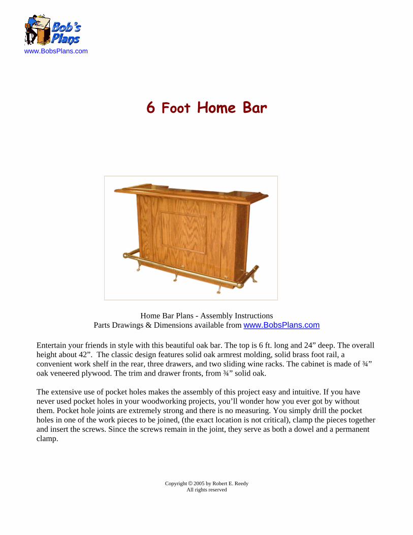
6 Foot Home Bar
Home Bar Plans - Assembly InstructionsParts Drawings & Dimensions available from www.BobsPlans.com
Entertain your friends in style with this beautiful oak bar. The top is 6 ft. long and 24” deep. The overallheight about 42”. The classic design features solid oak armrest molding, solid brass foot rail, aconvenient work shelf in the rear, three drawers, and two sliding wine racks. The cabinet is made of ¾”oak veneered plywood. The trim and drawer fronts, from ¾” solid oak.
The extensive use of pocket holes makes the assembly of this project easy and intuitive. If you havenever used pocket holes in your woodworking projects, you’ll wonder how you ever got by withoutthem. Pocket hole joints are extremely strong and there is no measuring. You simply drill the pocketholes in one of the work pieces to be joined, (the exact location is not critical), clamp the pieces togetherand insert the screws. Since the screws remain in the joint, they serve as both a dowel and a permanentclamp.
Copyright © 2005 by Robert E. ReedyAll rights reserved

Table of Contents
Part 1 - Assembly Instructions
Attach Drawer Slides ..................................................................... 1
Attach Wine Rack Slides - Assemble Bottom ............................. 2
Attach Vertical Dividers & Kick Panel ........................................ 3
Attach Side Panels and Work Shelf ............................................... 4
Assemble Front & Side Panels ...................................................... 5
Attach Front and Side Trim ........................................................... 6
Install Upper Horizontal Trim ....................................................... 7
Arrangement of Rear Trim ............................................................ 8
Install Brackets & Measure Side Rail Length ............................... 9
Measure Front Rail Length - Assemble Rails .............................. 10
Assemble Armrest Molding ......................................................... 11
Drill Pocket Holes in the Top ...................................................... 12
Attach Rear Trim to the Top ........................................................ 13
Attach Risers to the Top .............................................................. 14
Attach Top to Molding & End Soffit ........................................... 15
Attach Center Soffit ..................................................................... 16
Assemble Drawers ....................................................................... 17
Assemble Wine Racks ................................................................. 18
Cutout Suggestions (1)..................................................................19
Cutout Suggestions (2)..................................................................20
Cutout Suggestions (3)..................................................................21
Additional Plans & Pocket Hole Jig Links ...................................22
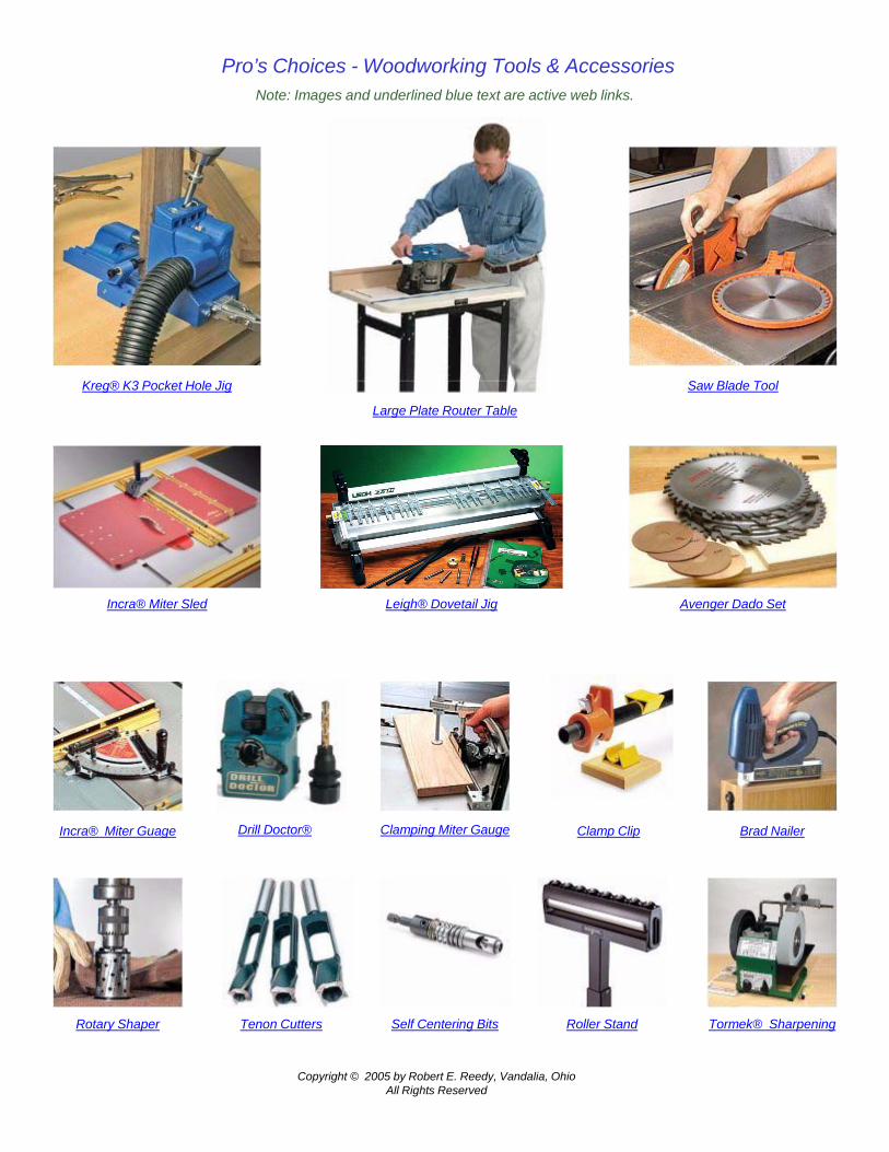
Pro’s Choices - Woodworking Tools & Accessories
Copyright © 2005 by Robert E. Reedy, Vandalia, OhioAll Rights Reserved
Note: Images and underlined blue text are active web links.
Leigh® Dovetail Jig Avenger Dado SetIncra® Miter Sled
Self Centering BitsRotary Shaper Roller Stand
Kreg® K3 Pocket Hole Jig
Large Plate Router Table
Saw Blade Tool
Drill Doctor® Clamping Miter Gauge Clamp Clip Brad Nailer
Tormek® SharpeningTenon Cutters
Incra® Miter Guage
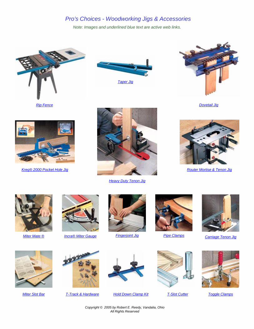
Pro’s Choices - Woodworking Jigs & Accessories
Copyright © 2005 by Robert E. Reedy, Vandalia, OhioAll Rights Reserved
Note: Images and underlined blue text are active web links.
Miter Mate ® Incra® Miter Gauge Carriage Tenon Jig
Hold Down Clamp KitT-Track & Hardware T-Slot Cutter Toggle Clamps
Pipe Clamps
Dovetail Jig
Taper Jig
Heavy Duty Tenon Jig
Rip Fence
Kreg® 2000 Pocket Hole Jig Router Mortise & Tenon Jig
Miter Slot Bar
Fingerjoint Jig
Materials You Will Need
Two Sheets of ¾” Oak Veneer Plywood - See Cutout Suggestions (1)
One Sheet of ½” Oak Veneer Plywood - See Cutout Suggestions (2)
One fourth Sheet of ¼” Hardboard - See Cutout Suggestions (2)
Four 5 ½” by 8’ by ¾” Oak Boards
One 6 ½” by 8’ by ¾” Oak Board
10 Ft. of Oak Armrest Molding - Rockler Item # 42768 & 42777 Link:http://www.rockler.com/findit.cfm?page=5762&sid=AF913
10 Ft. Brass Foot Rail Kit - Rockler Item # 57684 Link:http://www.rockler.com/findit.cfm?page=907&sid=AF913
Five Sets of 14” Drawer Slides (May be at local hardware stores) Rockler Item # 34835 Link:http://www.rockler.com/ecom7/product_details.cfm?offerings_id=1507&sid=AF913
Three Drawer Pulls (Available at Rockler or local hardware stores)
Pocket Hole Face Frame Screws (One or two pounds)
1” Flathead screws (About 50)
1” Finishing Nails (Less than a pound)
1 ½” Finishing Nails (Less than a pound)
7 Small Angle Brackets (Available at local hardware stores)
Tools You Will Need
Table SawDrill
Pocket Hole JigSander
Hand Tools
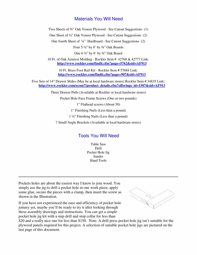
Pockets holes are about the easiest way I know to join wood. Yousimply use the jig to drill a pocket hole in one work piece, applysome glue, secure the pieces with a clamp, then insert the screw asshown in the Illustration.
If you have not experienced the ease and efficiency of pocket holejoinery yet, maybe you’ll be ready to try it after looking throughthese assembly drawings and instructions. You can get a simplepocket hole jig kit with a step drill and stop collar for less than$20 and a really nice one for less than $150. Note: A drill press pocket hole jig isn’t suitable for theplywood panels required for this project. A selection of suitable pocket hole jigs are pictured on thelast page of this document.
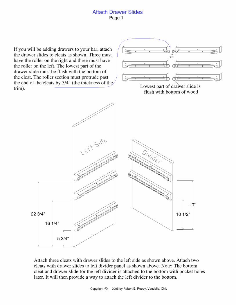
5 3/4"
16 1/4"
22 3/4" 10 1/2"
17"
Attach three cleats with drawer slides to the left side as shown above. Attach two cleats with drawer slides to left divider panel as shown above. Note: The bottom cleat and drawer slide for the left divider is attached to the bottom with pocket holes later. It will then provide a way to attach the left divider to the bottom.
Lowest part of drawer slide is flush with bottom of wood
If you will be adding drawers to your bar, attach the drawer slides to cleats as shown. Three must have the roller on the right and three must have the roller on the left. The lowest part of the drawer slide must be flush with the bottom of the cleat. The roller section must protrude past the end of the cleats by 3/4" (the thickness of the trim).
Copyright 2005 by Robert E. Reedy, Vandalia, OhioC
Attach Drawer SlidesPage 1
Copyright 2005 by Robert E. Reedy, Vandalia, OhioC
Attach Wine Rack Slides - Assemble BottomPage 2
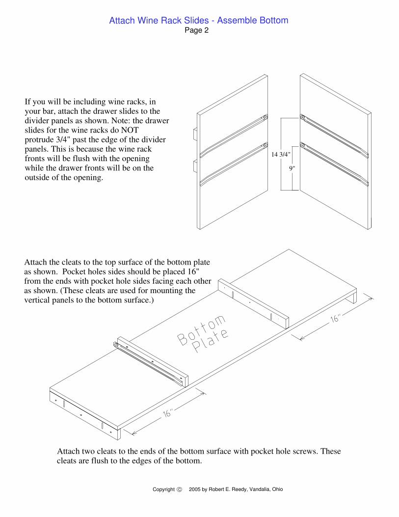
14 3/4"
9"
If you will be including wine racks, in your bar, attach the drawer slides to the divider panels as shown. Note: the drawer slides for the wine racks do NOT protrude 3/4" past the edge of the divider panels. This is because the wine rack fronts will be flush with the opening while the drawer fronts will be on the outside of the opening.
Attach two cleats to the ends of the bottom surface with pocket hole screws. These cleats are flush to the edges of the bottom.
Attach the cleats to the top surface of the bottom plate as shown. Pocket holes sides should be placed 16" from the ends with pocket hole sides facing each other as shown. (These cleats are used for mounting the vertical panels to the bottom surface.)
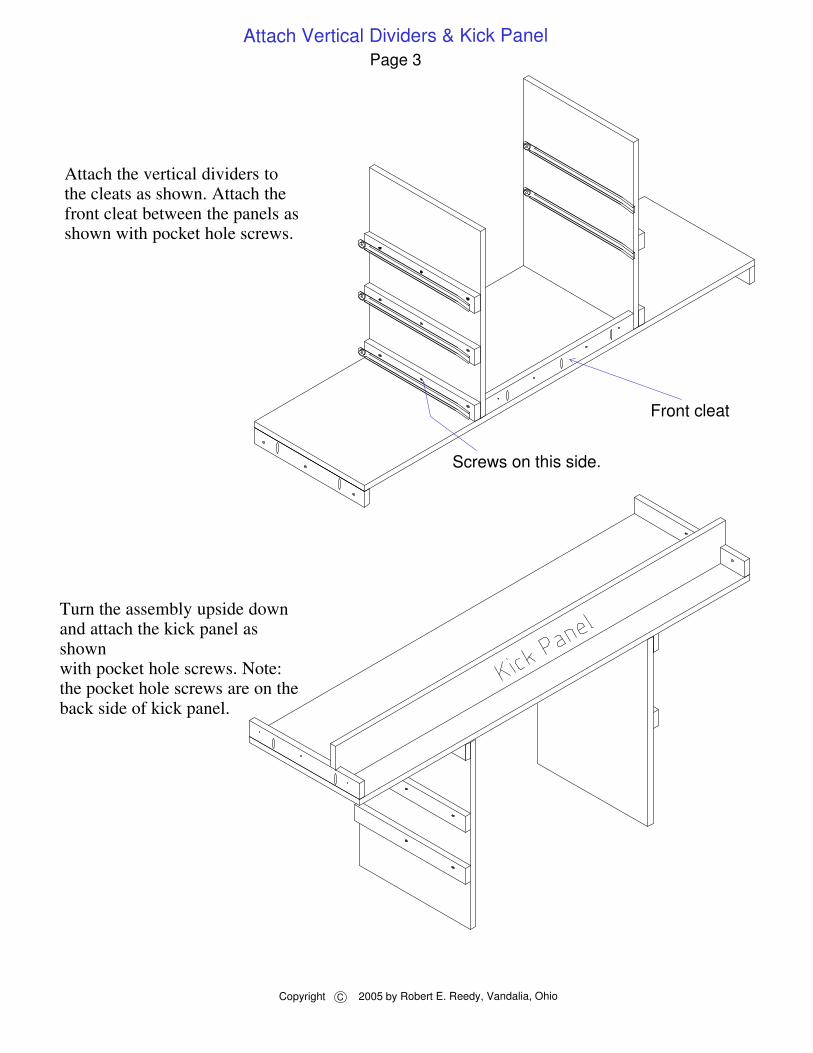
Front cleat
Attach the vertical dividers to the cleats as shown. Attach the front cleat between the panels as shown with pocket hole screws.
Turn the assembly upside down and attach the kick panel as shown with pocket hole screws. Note: the pocket hole screws are on theback side of kick panel.
Page 3Attach Vertical Dividers & Kick Panel
Screws on this side.
Copyright C 2005 by Robert E. Reedy, Vandalia, Ohio
Copyright 2005 by Robert E. Reedy, Vandalia, OhioC
Attach Side Panels and Work ShelfPage 4
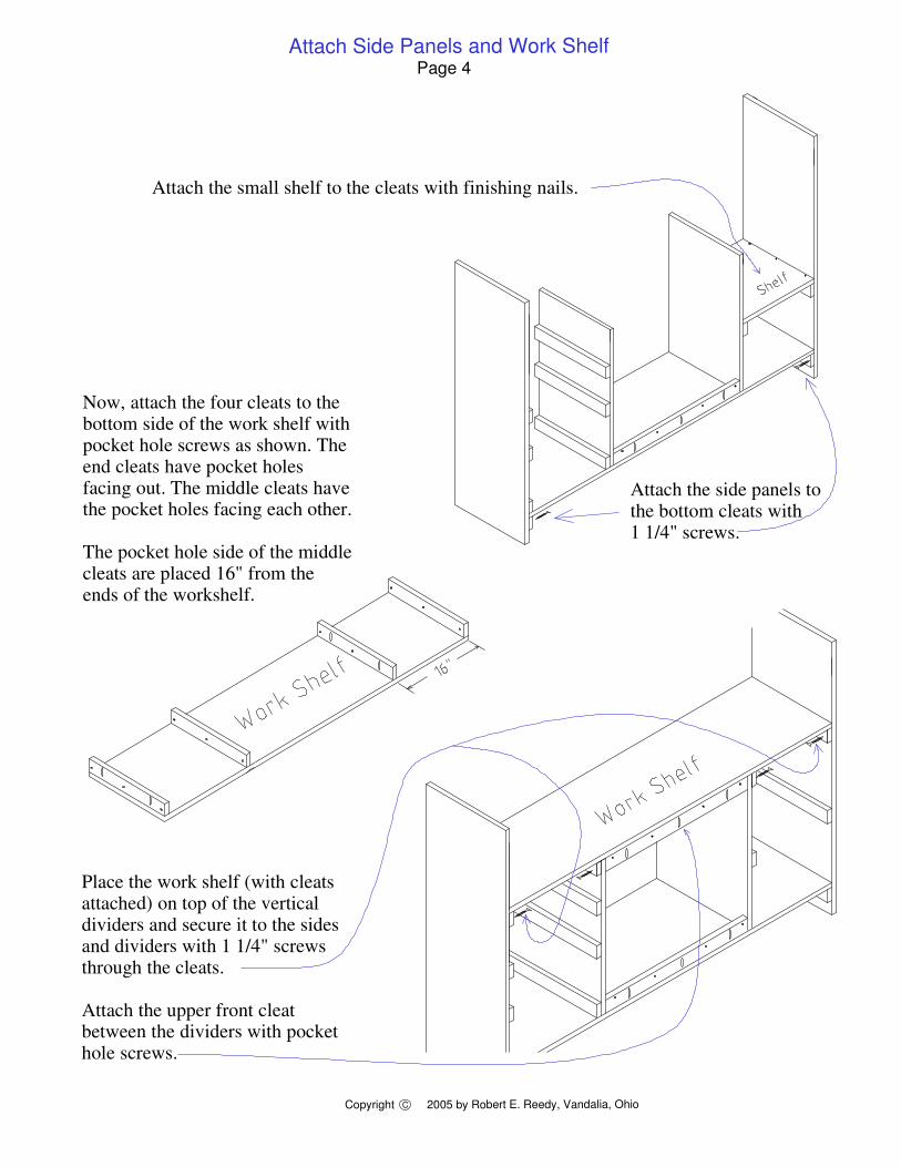
Attach the side panels to the bottom cleats with 1 1/4" screws.
Now, attach the four cleats to the bottom side of the work shelf with pocket hole screws as shown. The end cleats have pocket holes facing out. The middle cleats have the pocket holes facing each other.
The pocket hole side of the middle cleats are placed 16" from the ends of the workshelf.
Place the work shelf (with cleats attached) on top of the vertical dividers and secure it to the sides and dividers with 1 1/4" screws through the cleats.
Attach the upper front cleat between the dividers with pocket hole screws.
Attach the small shelf to the cleats with finishing nails.
Copyright 2005 by Robert E. Reedy, Vandalia, OhioC
Assemble Front & Side PanelsPage 5
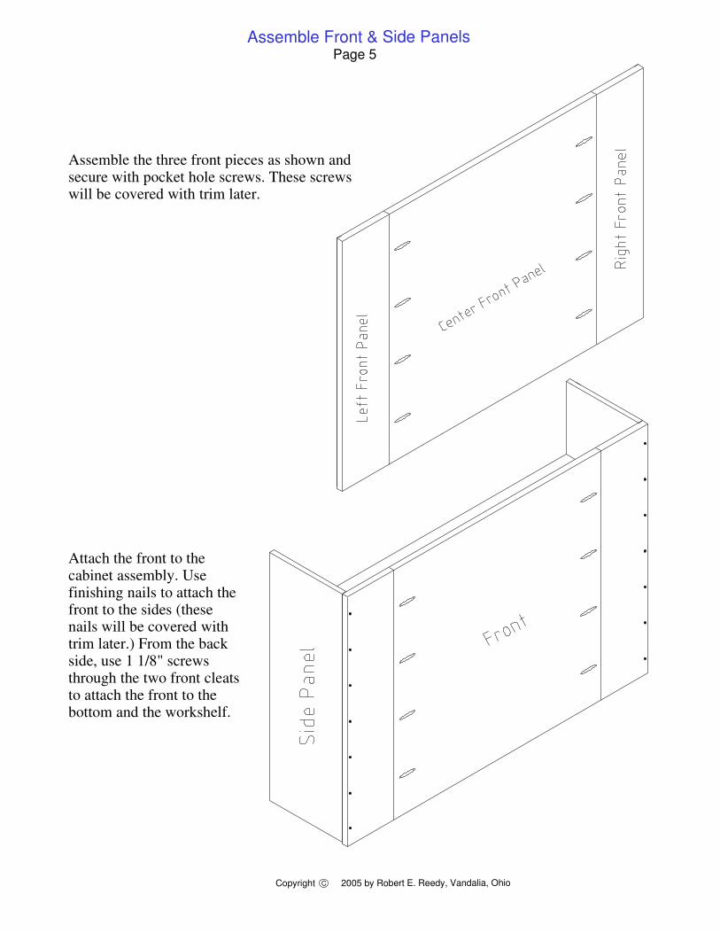
Assemble the three front pieces as shown and secure with pocket hole screws. These screws will be covered with trim later.
Attach the front to the cabinet assembly. Use finishing nails to attach the front to the sides (these nails will be covered with trim later.) From the back side, use 1 1/8" screws through the two front cleats to attach the front to the bottom and the workshelf.
Copyright 2005 by Robert E. Reedy, Vandalia, OhioC
Page 6
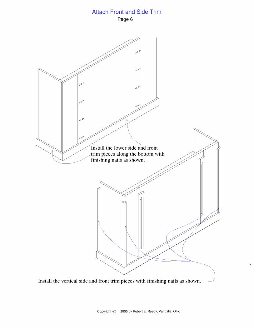
Install the vertical side and front trim pieces with finishing nails as shown.
Install the lower side and front trim pieces along the bottom with finishing nails as shown.
Attach Front and Side Trim
Install Upper Horizontal TrimPage 7
Copyright 2005 by Robert E. Reedy, Vandalia, OhioC
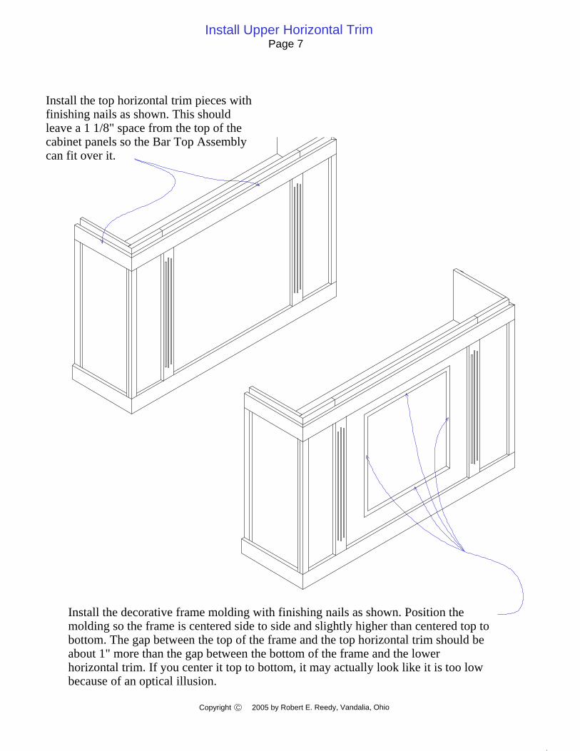
Install the decorative frame molding with finishing nails as shown. Position the molding so the frame is centered side to side and slightly higher than centered top to bottom. The gap between the top of the frame and the top horizontal trim should be about 1" more than the gap between the bottom of the frame and the lower horizontal trim. If you center it top to bottom, it may actually look like it is too low because of an optical illusion.
Install the top horizontal trim pieces with finishing nails as shown. This should leave a 1 1/8" space from the top of the cabinet panels so the Bar Top Assembly can fit over it.
Copyright 2005 by Robert E. Reedy, Vandalia, OhioC
Arrangement of Rear TrimPage 8
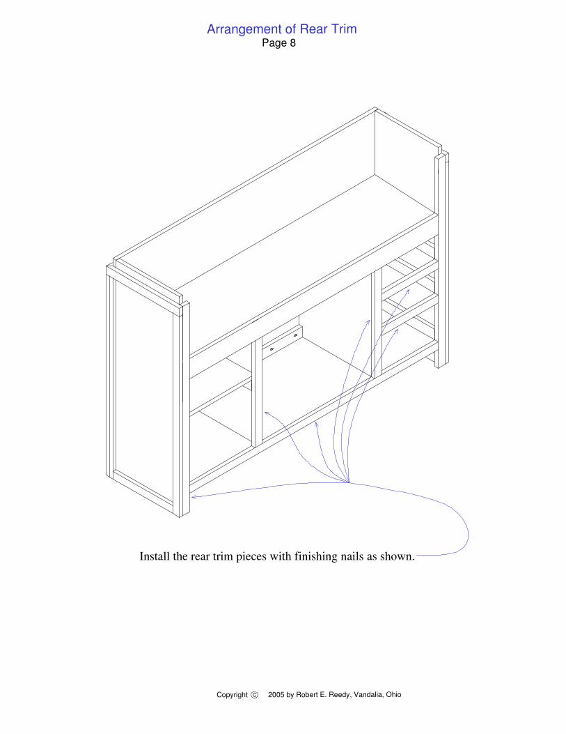
Install the rear trim pieces with finishing nails as shown.
Install Brackets & Measure Side Rail LengthPage 9
Copyright 2005 by Robert E. Reedy, Vandalia, Ohioc
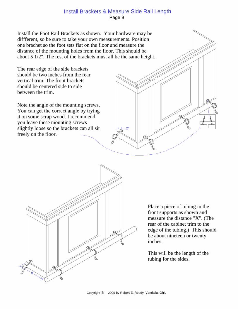
Place a piece of tubing in the front supports as shown and measure the distance "X". (The rear of the cabinet trim to the edge of the tubing.) This should be about nineteen or twenty inches.
This will be the length of the tubing for the sides.
Install the Foot Rail Brackets as shown. Your hardware may be diffferent, so be sure to take your own measurements. Position one brachet so the foot sets flat on the floor and measure the distance of the mounting holes from the floor. This should be about 5 1/2". The rest of the brackets must all be the same height.
Note the angle of the mounting screws. You can get the correct angle by trying it on some scrap wood. I recommend you leave these mounting screws slightly loose so the brackets can all sit freely on the floor.
The rear edge of the side brackets should be two inches from the rear vertical trim. The front brackets should be centered side to side between the trim.
2"
X
Measure Front Rail Length - Assemble RailsPage 10
Copyright 2005 by Robert E. Reedy, Vandalia, Ohioc
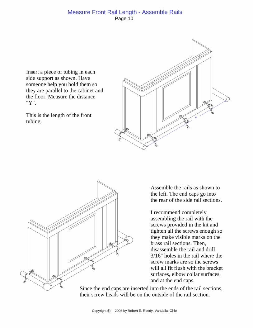
Insert a piece of tubing in each side support as shown. Have someone help you hold them so they are parallel to the cabinet and the floor. Measure the distance "Y".
This is the length of the front tubing.
Since the end caps are inserted into the ends of the rail sections, their screw heads will be on the outside of the rail section.
Assemble the rails as shown to the left. The end caps go into the rear of the side rail sections.
I recommend completely assembling the rail with the screws provided in the kit and tighten all the screws enough so they make visible marks on the brass rail sections. Then, disassemble the rail and drill 3/16" holes in the rail where the screw marks are so the screws will all fit flush with the bracket surfaces, elbow collar surfaces, and at the end caps.
Y

Assemble the Armrest MoldingPage 11
Copyright 2005 by Robert E. Reedy, Vandalia, Ohioc
The first step in assembling the top is to assemble the molding as shown above. Note: This drawing shows the molding in an upside down position.
The photos below show a couple of ways to attach the molding corners.
You can join the corners with pocket holes as shown in Figure 1. You'll need a small pocket hole jig for this. Note: Be sure to place the pocket holes so the screws don’t come through the top surface of the molding. Shorter screws may be necessary. Apply glue and secure with pocket hole screws.
You can secure the joints with finishing nails by temporarily securing the corners using some scrap plywood with pocket hole screws as shown in Figure 2. Drill two pocket holes on each of two sides of the plywood. Glue some 100 grit sandpaper to the surface of the scrap plywood where it contacts the lip of the molding (This makes it grip tighter.) Apply glue to the molding joint then secure the molding with the scrap plywood to hold the joint firmly together.
Turn the assembly over and secure with two finishing nails as shown (Be sure to pre-drill the nail holes so you don't split the wood). Countersink the nails so you can fill with putty later. Then you can remove the scrap plywood. The soffit which will be added later will serve to re-enforce the corner joints.

Drill Pocket Holes in the TopPage 12
Copyright 2005 by Robert E. Reedy, Vandalia, Ohioc
Drill pocket holes on the bottom surface of the top as shown. The two pocket holes along the long edge are used to secure the top to the molding. These two holes will keep the top centered in the molding and still allow for expansion or contraction.
26"
26"
2 1/4"
2 1/4"
The pocket holes along the back and cutout are for mounting the trim. The ones that are not marked may be placed in approximately the position shown.
Attach Rear Trim to the TopPage 13
Copyright 2005 by Robert E. Reedy, Vandalia, Ohioc
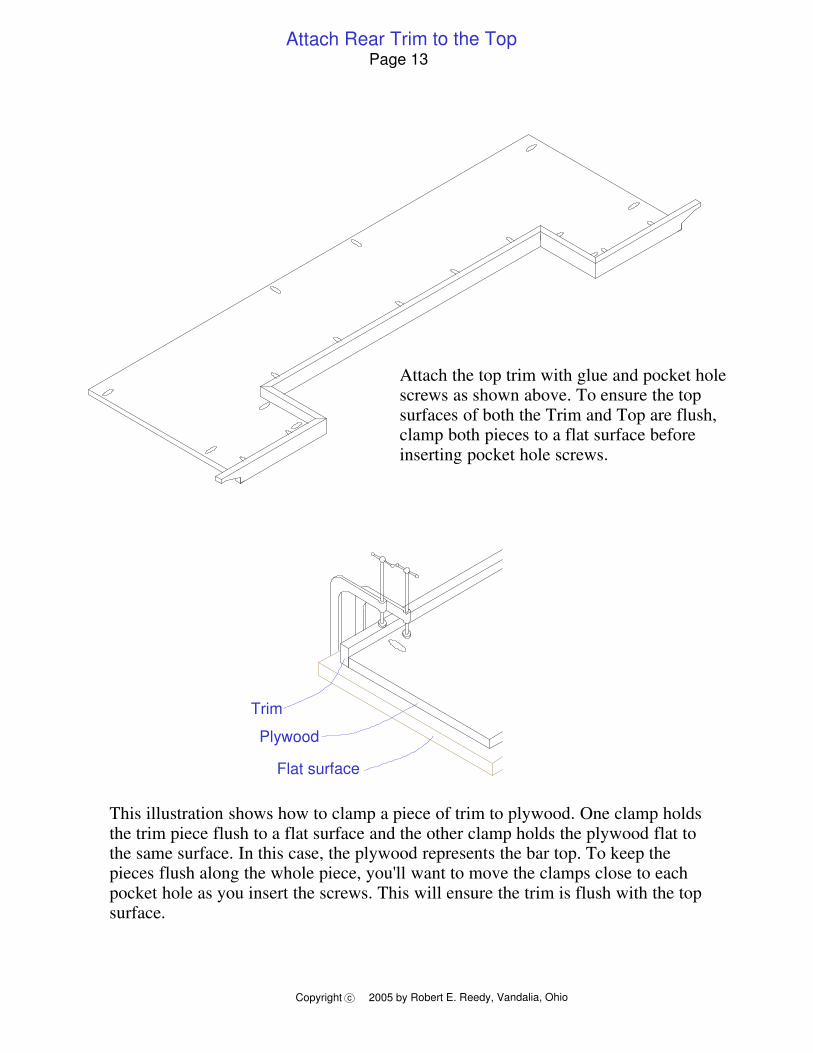
This illustration shows how to clamp a piece of trim to plywood. One clamp holds the trim piece flush to a flat surface and the other clamp holds the plywood flat to the same surface. In this case, the plywood represents the bar top. To keep the pieces flush along the whole piece, you'll want to move the clamps close to each pocket hole as you insert the screws. This will ensure the trim is flush with the top surface.
Attach the top trim with glue and pocket hole screws as shown above. To ensure the top surfaces of both the Trim and Top are flush, clamp both pieces to a flat surface before inserting pocket hole screws.
Flat surface
Plywood
Trim
Attach Risers to the TopPage 14
Copyright 2005 by Robert E. Reedy, Vandalia, Ohioc
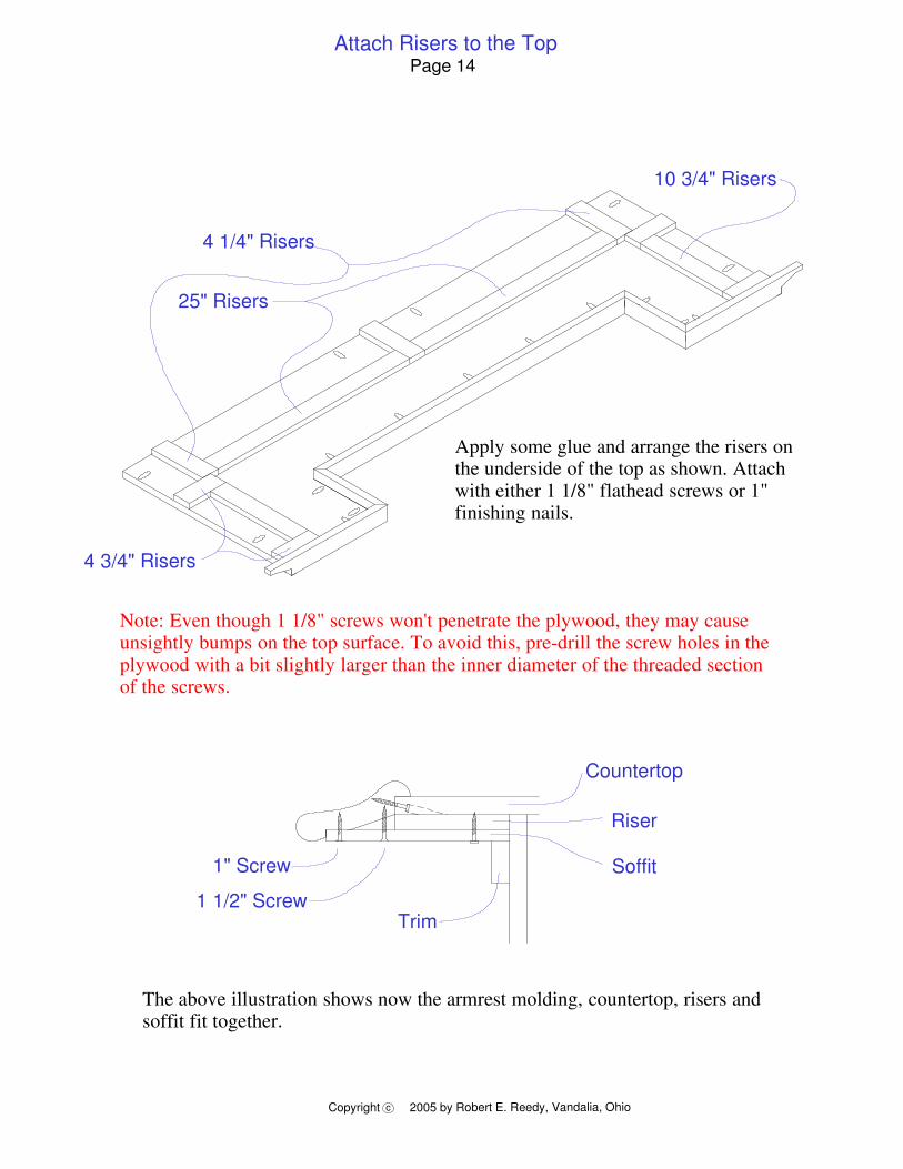
The above illustration shows now the armrest molding, countertop, risers and soffit fit together.
Countertop
Riser
Soffit
Trim
1" Screw
1 1/2" Screw
25" Risers
10 3/4" Risers
4 3/4" Risers
Apply some glue and arrange the risers on the underside of the top as shown. Attach with either 1 1/8" flathead screws or 1" finishing nails.
Note: Even though 1 1/8" screws won't penetrate the plywood, they may cause unsightly bumps on the top surface. To avoid this, pre-drill the screw holes in the plywood with a bit slightly larger than the inner diameter of the threaded section of the screws.
4 1/4" Risers
Attach Top to Molding & Attach End SoffitPage 15
Copyright 2005 by Robert E. Reedy, Vandalia, Ohioc
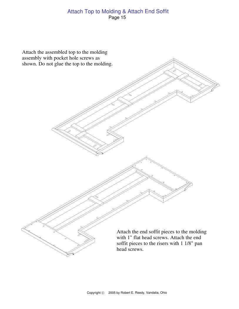
Attach the end soffit pieces to the molding with 1" flat head screws. Attach the end soffit pieces to the risers with 1 1/8" pan head screws.
Attach the assembled top to the molding assembly with pocket hole screws as shown. Do not glue the top to the molding.
Attach Center SoffitPage 16
Copyright 2005 by Robert E. Reedy, Vandalia, Ohioc
54"
14 3/4"
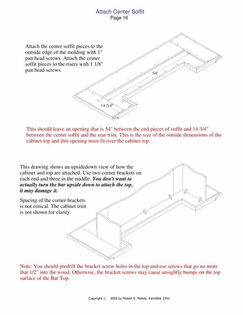
Attach the center soffit pieces to the outside edge of the molding with 1" pan head screws. Attach the center soffit pieces to the risers with 1 1/8" pan head screws.
This should leave an opening that is 54" between the end pieces of soffit and 14 3/4" between the center soffit and the rear trim. This is the size of the outside dimensions of the cabinet top and this opening must fit over the cabinet top.
This drawing shows an upsidedown view of how the cabinet and top are attached. Use two corner brackets on each end and three in the middle. You don't want to actually turn the bar upside down to attach the top, it may damage it.
Spacing of the corner brackets is not critical. The cabinet trim is not shown for clarity.
Note: You should predrill the bracket screw holes in the top and use screws that go no more that 1/2" into the wood. Otherwise, the bracket screws may cause unsightly bumps on the top surface of the Bar Top.
Assemble DrawersPage 17
Copyright 2005 by Robert E. Reedy, Vandalia, Ohioc
Step 2 Step 3
Left Side
Step 1
Right Side
Front
Back
Step 5Step 4
Drawer Slide
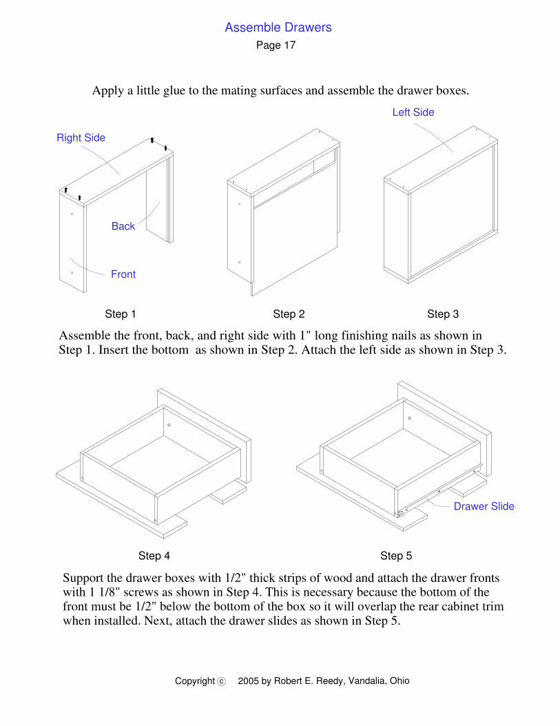
Support the drawer boxes with 1/2" thick strips of wood and attach the drawer fronts with 1 1/8" screws as shown in Step 4. This is necessary because the bottom of the front must be 1/2" below the bottom of the box so it will overlap the rear cabinet trim when installed. Next, attach the drawer slides as shown in Step 5.
Apply a little glue to the mating surfaces and assemble the drawer boxes.
Assemble the front, back, and right side with 1" long finishing nails as shown in Step 1. Insert the bottom as shown in Step 2. Attach the left side as shown in Step 3.
Assemble Wine RacksPage 18
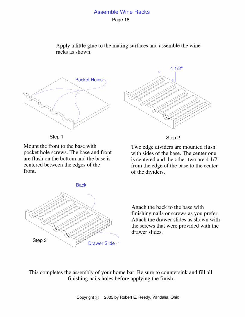
Apply a little glue to the mating surfaces and assemble the wine racks as shown.
Copyright 2005 by Robert E. Reedy, Vandalia, Ohioc
4 1/2"
Step 2
Two edge dividers are mounted flush with sides of the base. The center one is centered and the other two are 4 1/2" from the edge of the base to the center of the dividers.
Step 1
Mount the front to the base with pocket hole screws. The base and front are flush on the bottom and the base is centered between the edges of the front.
Pocket Holes
Back
Drawer Slide
Attach the back to the base with finishing nails or screws as you prefer. Attach the drawer slides as shown with the screws that were provided with the drawer slides.
Step 3
This completes the assembly of your home bar. Be sure to countersink and fill all finishing nails holes before applying the finish.
Copyright 2005 by Robert E. Reedy, Vandalia, OhioC
Bar Top
Cabnit Side Cabnit Side
Divider
Divider
Kick Panel
Left Front Panel
14" Cleat14" Cleat
Front CleatFront Cleat
Small Shelf14"
Right Front Panel
Workshelf
Bottom
Center Front Panel
41"Direction of Grain:
Wine Rack Bottom Wine Rack Bottom
14" Cleat14" Cleat
14" Cleat14" Cleat14" Cleat
14" Cleat14" Cleat14" Cleat14" Cleat
14" Cleat14" Cleat14" Cleat
14" Cleat
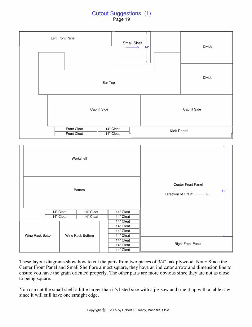
These layout diagrams show how to cut the parts from two pieces of 3/4" oak plywood. Note: Since the Center Front Panel and Small Shelf are almost square, they have an indicator arrow and dimension line to ensure you have the grain oriented properly. The other parts are more obvious since they are not as close to being square.
You can cut the small shelf a little larger than it's listed size with a jig saw and true it up with a table saw since it will still have one straight edge.
Cutout Suggestions (1)Page 19
Cutout Suggestions (2)
Copyright 2005 by Robert E. Reedy, Vandalia, OhioC
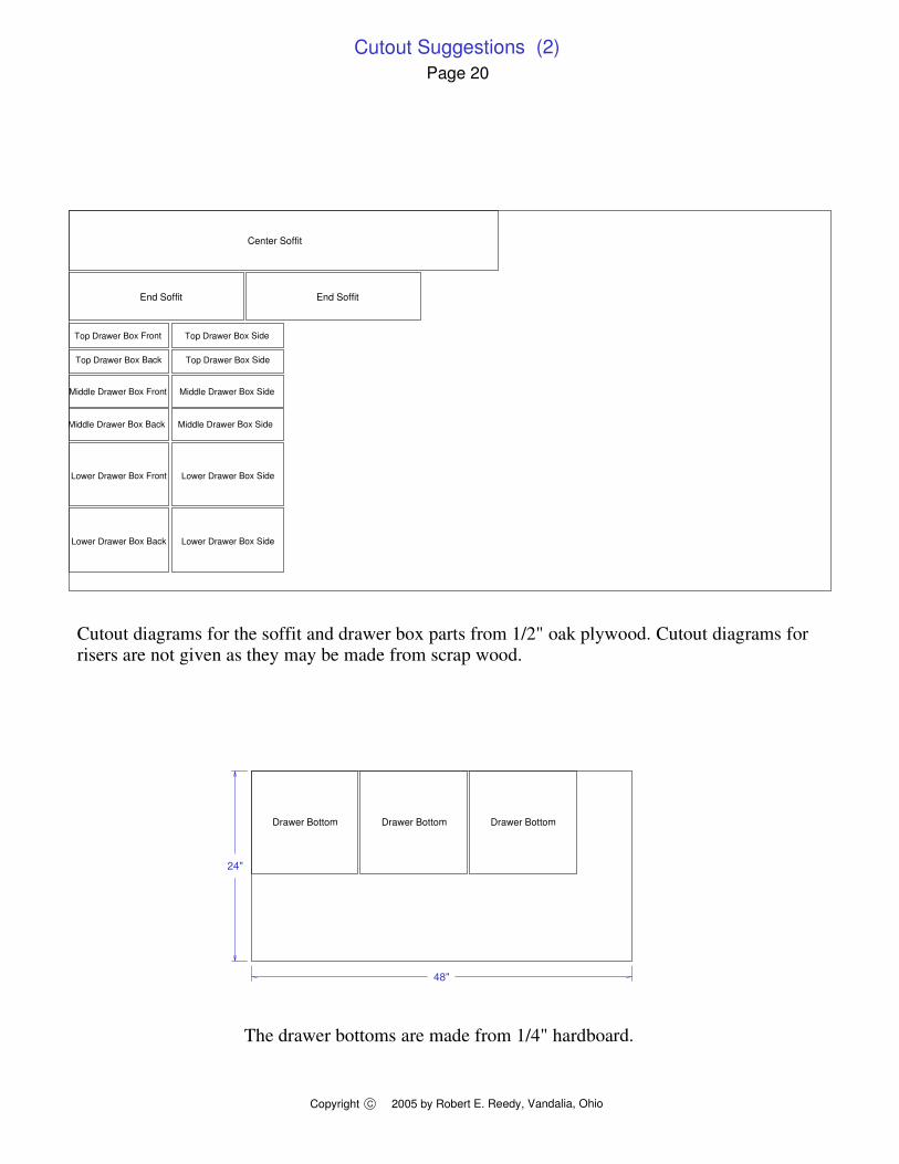
The drawer bottoms are made from 1/4" hardboard.
Page 20
End Soffit End Soffit
Center Soffit
Cutout diagrams for the soffit and drawer box parts from 1/2" oak plywood. Cutout diagrams for risers are not given as they may be made from scrap wood.
Top Drawer Box Front
Top Drawer Box Back
Middle Drawer Box Front
Middle Drawer Box Back
Lower Drawer Box Front
Lower Drawer Box Back
Top Drawer Box Side
Top Drawer Box Side
Middle Drawer Box Side
Middle Drawer Box Side
Lower Drawer Box Side
Lower Drawer Box Side
Drawer Bottom Drawer Bottom Drawer Bottom
24"
48"
Cut
out S
ugge
stio
ns (
3)P
age
21
Cop
yrig
ht20
05 b
y R
ober
t E. R
eedy
, Van
dalia
, Ohi
oC
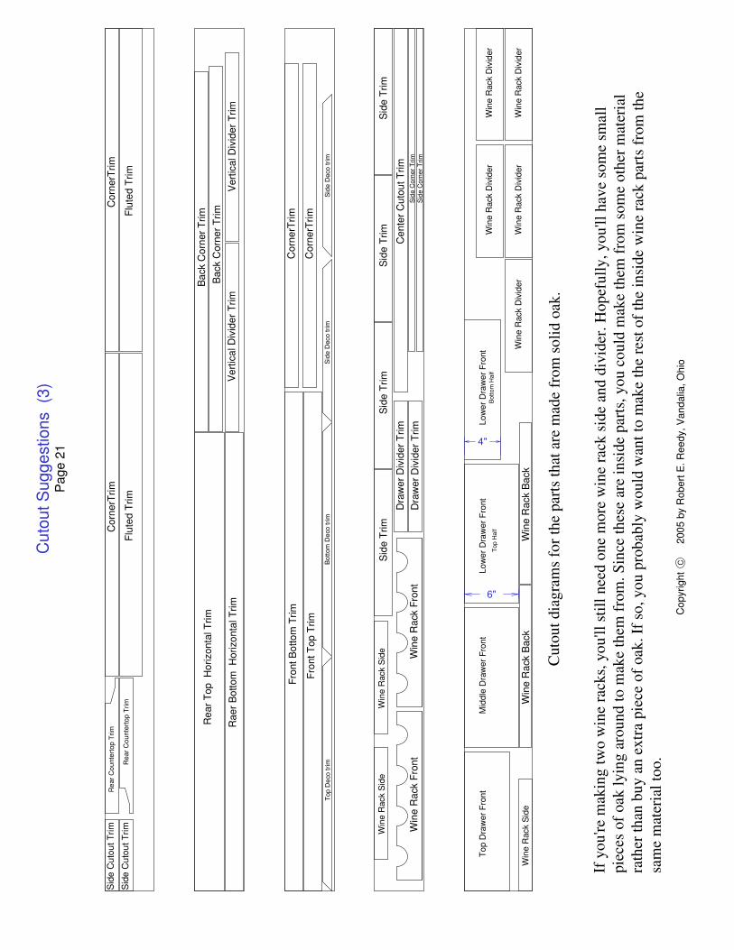
If y
ou're
mak
ing
two
win
e ra
cks,
you
'll s
till n
eed
one
mor
e w
ine
rack
sid
e an
d di
vide
r. H
opef
ully
, you
'll h
ave
som
e sm
all
piec
es o
f oak
lyin
g ar
ound
to m
ake
them
from
. Sin
ce th
ese
are
insi
de p
arts
, you
cou
ld m
ake
them
from
som
e ot
her m
ater
ial
rath
er th
an b
uy a
n ex
tra
piec
e of
oak
. If s
o, y
ou p
roba
bly
wou
ld w
ant t
o m
ake
the
rest
of t
he in
side
win
e ra
ck p
arts
from
the
sam
e m
ater
ial t
oo.
Cor
nerT
rimC
orne
rTrim
Rea
r Cou
nte r
top
Trim
Rea
r Cou
nte r
top
Trim
Sid
e C
utou
t Trim
Sid
e C
utou
t Trim
Flut
ed T
rimFl
uted
Trim
Rea
r Top
Hor
izon
tal T
rim
Rae
r Bot
tom
Hor
izon
tal T
rim
Bac
k C
orne
r Trim
Bac
k C
orne
r Trim
Ver
tical
Div
ider
Trim
Ver
tical
Div
ider
Trim
Fron
t Bot
tom
Trim
Cor
nerT
rim
Cor
nerT
rim
Top
Dec
o tri
mB
otto
m D
eco
trim
Sid
e D
eco
trim
Sid
e D
eco
trim
Fron
t Top
Trim
Sid
e Tr
imS
ide
Trim
Sid
e Tr
imS
ide
Trim
Cen
ter C
utou
t Trim
Dra
wer
Div
ider
Trim
Dra
wer
Div
ider
Trim
Sid
e C
orne
r Trim
S
ide
Cor
ner T
rim
Win
e R
ack
Sid
eW
ine
Rac
k S
ide
Win
e R
ack
Fron
tW
ine
Rac
k Fr
ont
Mid
dle
Dra
wer
Fro
ntTo
p D
raw
er F
ront
Low
er D
raw
er F
ront
Top
Hal
f
Low
er D
raw
er F
ront
Bot
tom
Hal
f
Win
e R
ack
Sid
eW
ine
Rac
k D
ivid
er
Win
e R
ack
Div
ider
Win
e R
ack
Div
ider
Win
e R
ack
Div
ider
Win
e R
ack
Div
ider
Win
e R
ack
Bac
kW
ine
Rac
k B
ack
6"
4"
Cut
out d
iagr
ams
for t
he p
arts
that
are
mad
e fr
om s
olid
oak
.
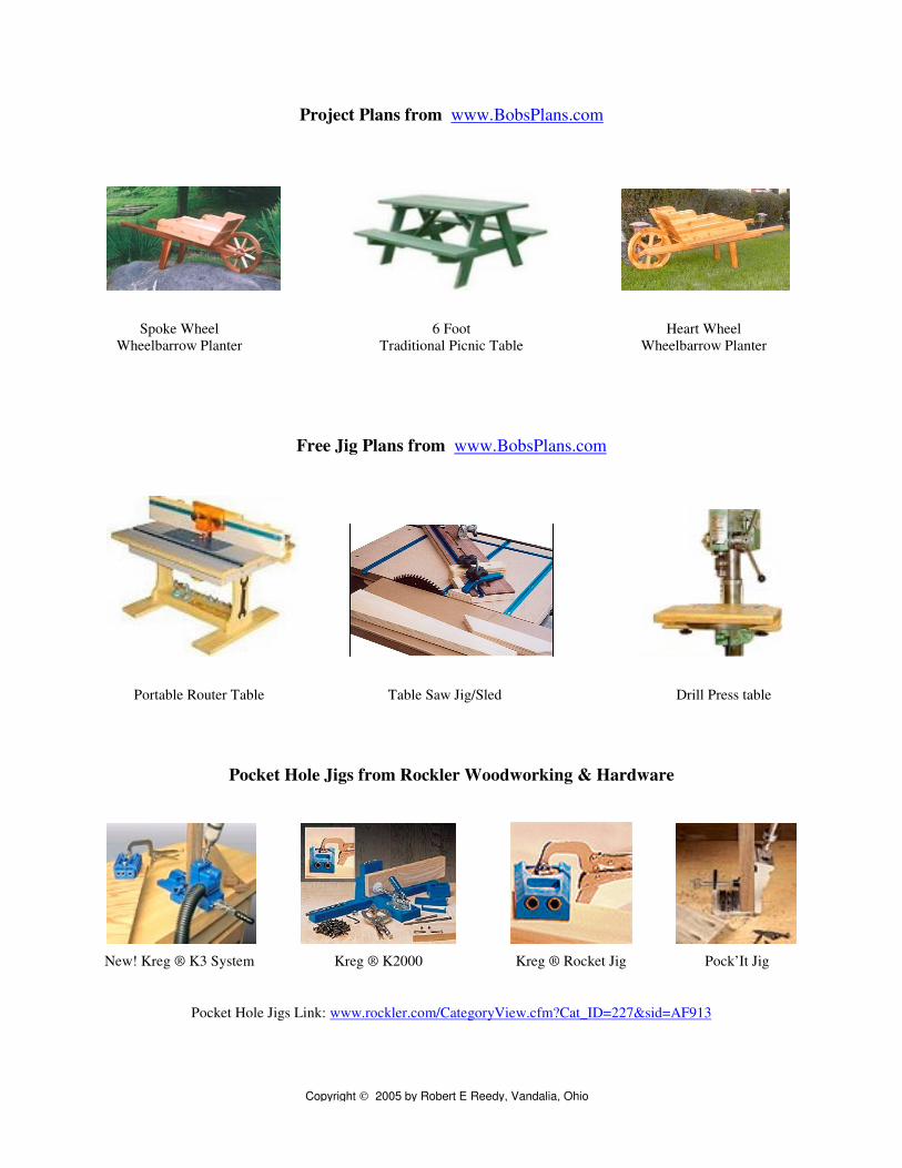
Project Plans from www.BobsPlans.com
Spoke Wheel 6 Foot Heart WheelWheelbarrow Planter Traditional Picnic Table Wheelbarrow Planter
Free Jig Plans from www.BobsPlans.com
Portable Router Table Table Saw Jig/Sled Drill Press table
Pocket Hole Jigs from Rockler Woodworking & Hardware
New! Kreg ® K3 System Kreg ® K2000 Kreg ® Rocket Jig Pock’It Jig
Pocket Hole Jigs Link: www.rockler.com/CategoryView.cfm?Cat_ID=227&sid=AF913
Copyright 2005 by Robert E Reedy, Vandalia, Ohio