Embed Size (px)
Citation preview
7-1
EE 319KIntroduction to Embedded Systems
Lecture 7: Phase-locked-loop, Data structures,
Finite state machines, Interrupts
Bard, Gerstlauer, Valvano, Yerraballi

7-2
Agenda
RecapIndexed Addressing and Pointers
o In C: Address of (&), Pointer to (*)Data Structures: Arrays, Strings
o Length: hardcoded vs. embedded vs. sentinelo Array access: indexed vs. pointer arithmetic
Functional DebuggingSysTick Timer
OutlinePhase Lock Loop (PLL)Data structuresFinite State Machines, Linked-listsInterrupts
Bard, Gerstlauer, Valvano, Yerraballi

7-3
Phase-Lock-Loop
Internal oscillator requires minimal power but is imprecise External crystal provides stable bus clock TM4C123 is equipped with 16 MHz crystal and bus clock can be
set to a maximum of 80 MHz
RefClk
MainOsc
Externalcrystal
OSCSRC
16 MHzInternal Osc /4
Phase/FreqDetector
ChargePump/LPF
Up
Down
/m
VCO
BYPASS
Phase-Lock-Loop
400 MHz
USESYSDIV
/n
SYSDIV
Mux
Mux
Mux
00
01
10*
0
1
0
1
XTAL
/2
DIV400
Mux
0
1
200 MHz
30 kHzInternal Osc
11** can't drivethe PLL
Bard, Gerstlauer, Valvano, Yerraballi
7-4
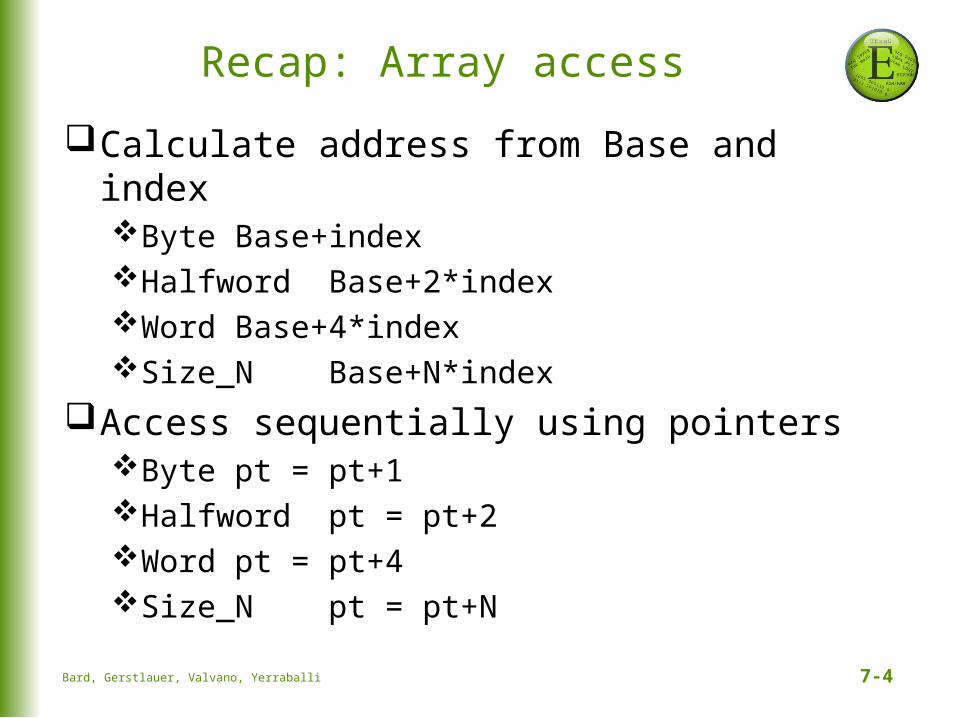
Recap: Array access
Calculate address from Base and indexByte Base+indexHalfword Base+2*indexWord Base+4*indexSize_N Base+N*index
Access sequentially using pointersByte pt = pt+1Halfword pt = pt+2Word pt = pt+4Size_N pt = pt+N
Bard, Gerstlauer, Valvano, Yerraballi
7-5
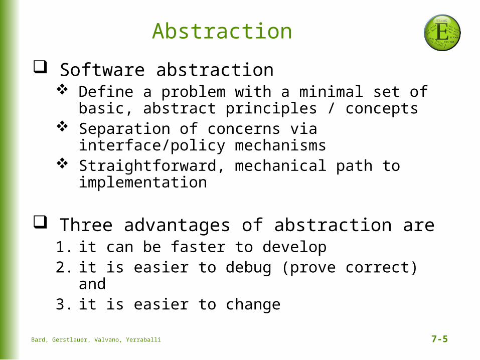
Abstraction
Software abstraction Define a problem with a minimal set of
basic, abstract principles / concepts Separation of concerns via interface/policy
mechanisms Straightforward, mechanical path to
implementation
Three advantages of abstraction are1. it can be faster to develop2. it is easier to debug (prove correct) and3. it is easier to change
Bard, Gerstlauer, Valvano, Yerraballi
7-6
Finite State Machine (FSM)
Finite State Machines (FSMs)Set of inputs, outputs, states and transitionsState graph defines input/output relationship
What is a state?Description of current conditions
What is a state graph?Graphical interconnection between states
What is a controller?Software that inputs, outputs, changes stateAccesses the state graph
Bard, Gerstlauer, Valvano, Yerraballi
7-7
Finite State Machine (FSM)
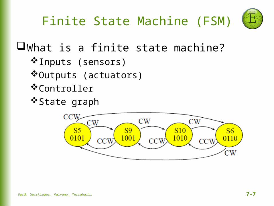
What is a finite state machine?Inputs (sensors)Outputs (actuators)ControllerState graph
Bard, Gerstlauer, Valvano, Yerraballi

7-8
Finite State Machine (FSM)
Moore FSMoutput value depends only on the current state, inputs affect the state transitionssignificance is being in a state
Input: when to change stateOutput: definition of being in that state
goN
30
Next if input is 01 or 11
100001
Wait time
01,1100,10waitN
5100010
goE
30001100
waitE
5010100
00,01,10,11 10,11
00,01
00,01,10,11
Output
Bard, Gerstlauer, Valvano, Yerraballi
7-9
Finite State Machine (FSM)
Moore FSM Execution Sequence1. Perform output corresponding to the current
state2. Wait a prescribed amount of time (optional)3. Read inputs4. Change state, which depends on the input and
the current state5. Go back to 1. and repeat
Bard, Gerstlauer, Valvano, Yerraballi
7-10
Finite State Machine (FSM)
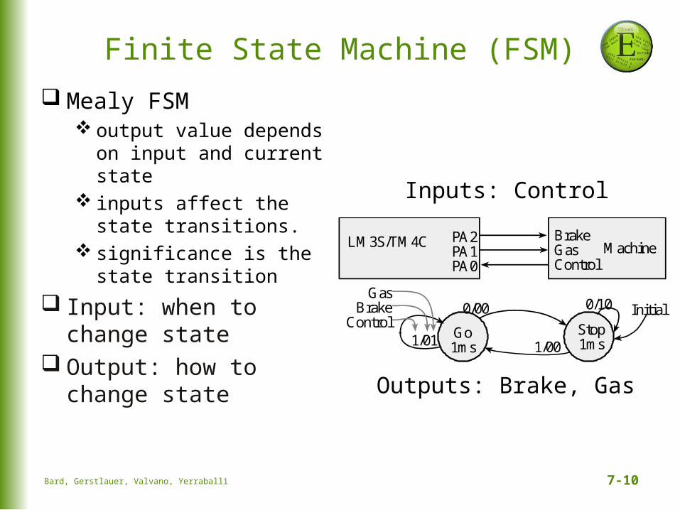
Mealy FSM output value depends
on input and current state
inputs affect the state transitions.
significance is the state transition
Input: when to change state
Output: how to change state
Inputs: Control
Outputs: Brake, Gas
PA2PA1PA0
LM3S/TM4C BrakeGasControl
Machine
Go1ms
Stop1ms
0/00
1/01
0/10
1/00
GasBrake
ControlInitial
Bard, Gerstlauer, Valvano, Yerraballi
7-11
Finite State Machine (FSM)
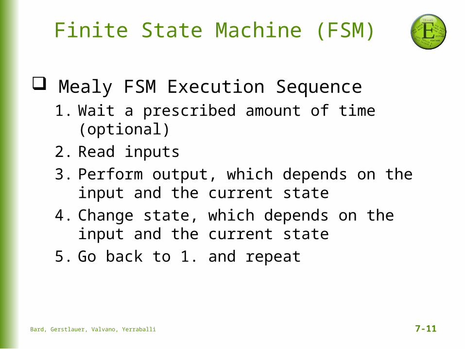
Mealy FSM Execution Sequence1. Wait a prescribed amount of time (optional)2. Read inputs 3. Perform output, which depends on the input
and the current state4. Change state, which depends on the input
and the current state5. Go back to 1. and repeat
Bard, Gerstlauer, Valvano, Yerraballi
7-12
Finite State Machine (FSM)
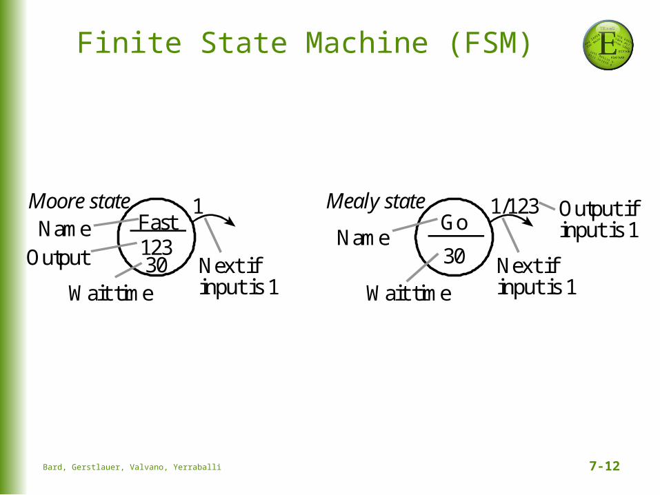
Fast
30 Next ifinput is 1
123
Wait time
1Moore state
Output
Go
30 Next ifinput is 1Wait time
1/123Mealy state Output ifinput is 1NameName
Bard, Gerstlauer, Valvano, Yerraballi
7-13
FSM Implementation
Data Structure embodies the FSMmultiple identically-structured nodesstatically-allocated fixed-size linked structuresone-to-one mapping FSM state graph and linked
structureone structure for each state
Linked Structurepointer (or link) to other nodes (define next
states)
Table structureindices to other nodes (define next states)
Bard, Gerstlauer, Valvano, Yerraballi
7-14
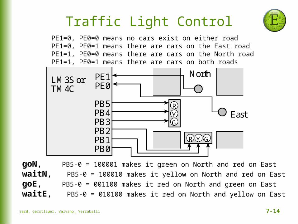
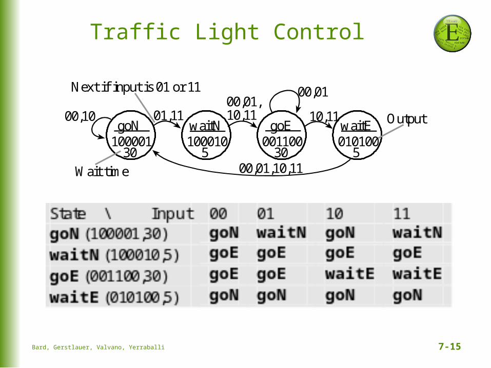
Traffic Light ControlPE1=0, PE0=0 means no cars exist on either roadPE1=0, PE0=1 means there are cars on the East roadPE1=1, PE0=0 means there are cars on the North roadPE1=1, PE0=1 means there are cars on both roads
goN, PB5-0 = 100001 makes it green on North and red on East
waitN, PB5-0 = 100010 makes it yellow on North and red on East
goE, PB5-0 = 001100 makes it red on North and green on East
waitE, PB5-0 = 010100 makes it red on North and yellow on East
North
EastR
GY
R Y G
PE1PE0
PB5PB4PB3PB2PB1PB0
LM3S orTM4C
Bard, Gerstlauer, Valvano, Yerraballi
7-15
Traffic Light Control
goN
30
Next if input is 01 or 11
100001
Wait time
01,1100,10waitN
5100010
goE
30001100
waitE
5010100
00,01,10,11 10,11
00,01
00,01,10,11
Output
Bard, Gerstlauer, Valvano, Yerraballi
7-16
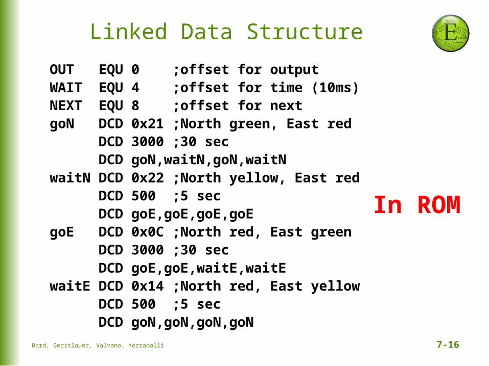
Linked Data Structure
OUT EQU 0 ;offset for output WAIT EQU 4 ;offset for time (10ms) NEXT EQU 8 ;offset for next goN DCD 0x21 ;North green, East red DCD 3000 ;30 sec DCD goN,waitN,goN,waitNwaitN DCD 0x22 ;North yellow, East red DCD 500 ;5 sec DCD goE,goE,goE,goEgoE DCD 0x0C ;North red, East green DCD 3000 ;30 sec DCD goE,goE,waitE,waitEwaitE DCD 0x14 ;North red, East yellow DCD 500 ;5 sec DCD goN,goN,goN,goN
In ROM
Bard, Gerstlauer, Valvano, Yerraballi
7-17
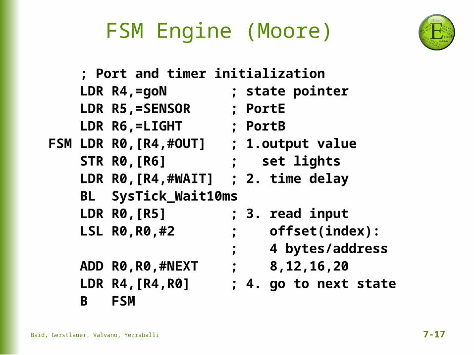
FSM Engine (Moore)
; Port and timer initialization LDR R4,=goN ; state pointer LDR R5,=SENSOR ; PortE LDR R6,=LIGHT ; PortBFSM LDR R0,[R4,#OUT] ; 1.output value STR R0,[R6] ; set lights LDR R0,[R4,#WAIT] ; 2. time delay BL SysTick_Wait10ms LDR R0,[R5] ; 3. read input LSL R0,R0,#2 ; offset(index): ; 4 bytes/address ADD R0,R0,#NEXT ; 8,12,16,20 LDR R4,[R4,R0] ; 4. go to next state B FSM
Bard, Gerstlauer, Valvano, Yerraballi

7-18
Linked Data Structure in Cconst struct State { uint32_t Out; uint32_t Time; // 10 ms units const struct State *Next[4];}; typedef const struct State STyp;
#define goN &FSM[0]#define waitN &FSM[1]#define goE &FSM[2]#define waitE &FSM[3]STyp FSM[4] = { {0x21,3000,{goN,waitN,goN,waitN}}, {0x22, 500,{goE,goE,goE,goE}}, {0x0C,3000,{goE,goE,waitE,waitE}}, {0x14, 500,{goN,goN,goN,goN}}};
Bard, Gerstlauer, Valvano, Yerraballi
7-19
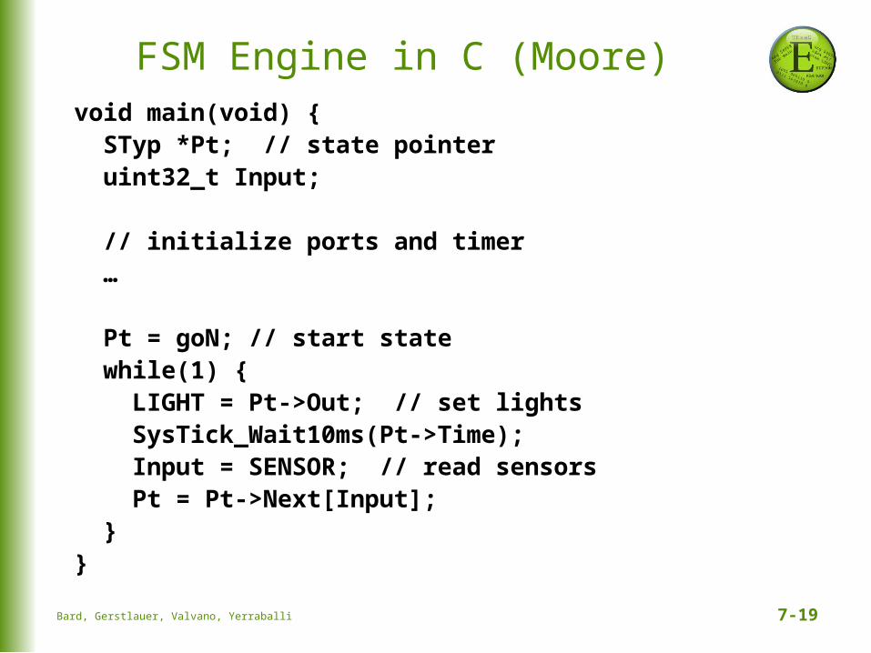
FSM Engine in C (Moore)void main(void) { STyp *Pt; // state pointer uint32_t Input; // initialize ports and timer …
Pt = goN; // start state while(1) { LIGHT = Pt->Out; // set lights SysTick_Wait10ms(Pt->Time); Input = SENSOR; // read sensors Pt = Pt->Next[Input]; }}
Bard, Gerstlauer, Valvano, Yerraballi

7-20
Interrupts
An interrupt is the automatic transfer of software execution in response to a hardware event (trigger) that is asynchronous with current software execution.external I/O device (like a keyboard or
printer) oran internal event (like an op code fault, or a
periodic timer.)
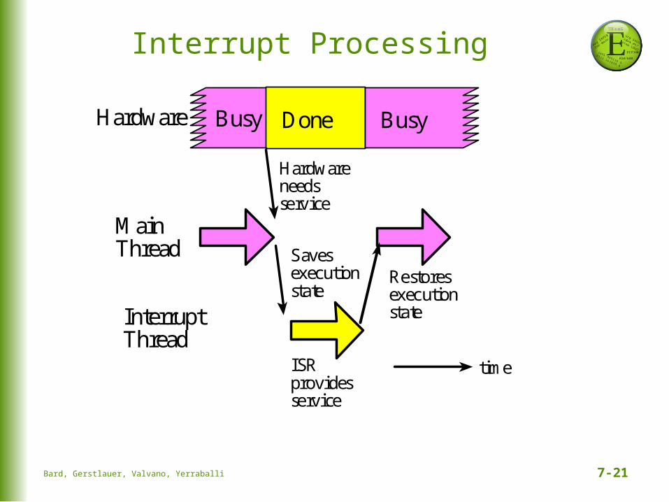
Occurs when the hardware needs or can service (busy to done state transition)
Bard, Gerstlauer, Valvano, Yerraballi
7-21
Interrupt Processing
Hardware
Hardwareneedsservice
ISRprovidesservice
Busy Done Busy
Savesexecutionstate
RestoresexecutionstateInterrupt
Thread
MainThread
time
Bard, Gerstlauer, Valvano, Yerraballi
7-22
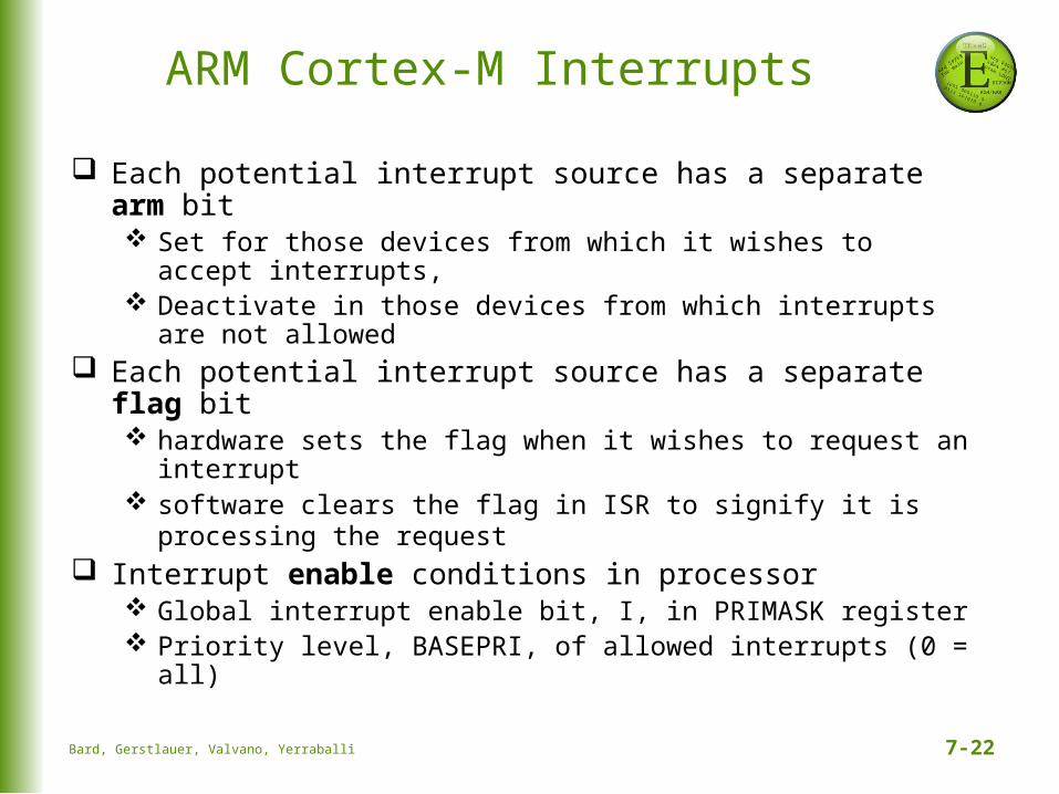
ARM Cortex-M Interrupts
Each potential interrupt source has a separate arm bit Set for those devices from which it wishes to accept
interrupts, Deactivate in those devices from which interrupts are not
allowed Each potential interrupt source has a separate flag bit
hardware sets the flag when it wishes to request an interrupt
software clears the flag in ISR to signify it is processing the request
Interrupt enable conditions in processor Global interrupt enable bit, I, in PRIMASK register Priority level, BASEPRI, of allowed interrupts (0 = all)
Bard, Gerstlauer, Valvano, Yerraballi

7-23
Interrupt Conditions
Four conditions must be true simultaneously for an interrupt to occur:1. Arm: control bit for each possible source is set2. Enable: interrupts globally enabled (I=0 in PRIMASK)3. Level: interrupt level must be less than BASEPRI4. Trigger: hardware action sets source-specific flag
Interrupt remains pending if trigger is set but any other condition is not true Interrupt serviced once all conditions become true
Need to acknowledge interrupt Clear trigger flag or will get endless interrupts!
Bard, Gerstlauer, Valvano, Yerraballi

7-24
Interrupt Processing
1. The execution of the main program is suspended1. the current instruction is finished,2. suspend execution and push 8 registers (R0-R3, R12,
LR, PC, PSR) on the stack3. LR set to 0xFFFFFFF9 (indicates interrupt return)4. IPSR set to interrupt number5. sets PC to ISR address
2. The interrupt service routine (ISR) is executed clears the flag that requested the interrupt performs necessary operations communicates using global variables
3. The main program is resumed when ISR executes BX LR pulls the 8 registers from the stack
Bard, Gerstlauer, Valvano, Yerraballi
7-25
Registers
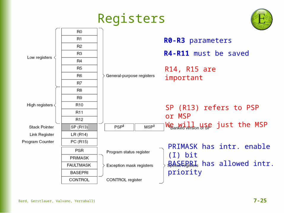
SP (R13) refers to PSP or MSPWe will use just the MSP
PRIMASK has intr. enable (I) bitBASEPRI has allowed intr. priority
R14, R15 are important
R0-R3 parameters
R4-R11 must be saved
Bard, Gerstlauer, Valvano, Yerraballi
7-26
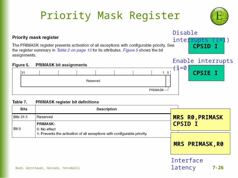
Priority Mask Register
CPSID I
CPSIE I
CPSID I
MRS PRIMASK,R0
MRS R0,PRIMASK
Interface latency
Disable interrupts (I=1)
Enable interrupts (I=0)
Bard, Gerstlauer, Valvano, Yerraballi

7-27
Program Status Register
Q = Saturation, T = Thumb bit
Accessed separately or all at once
Bard, Gerstlauer, Valvano, Yerraballi
7-28
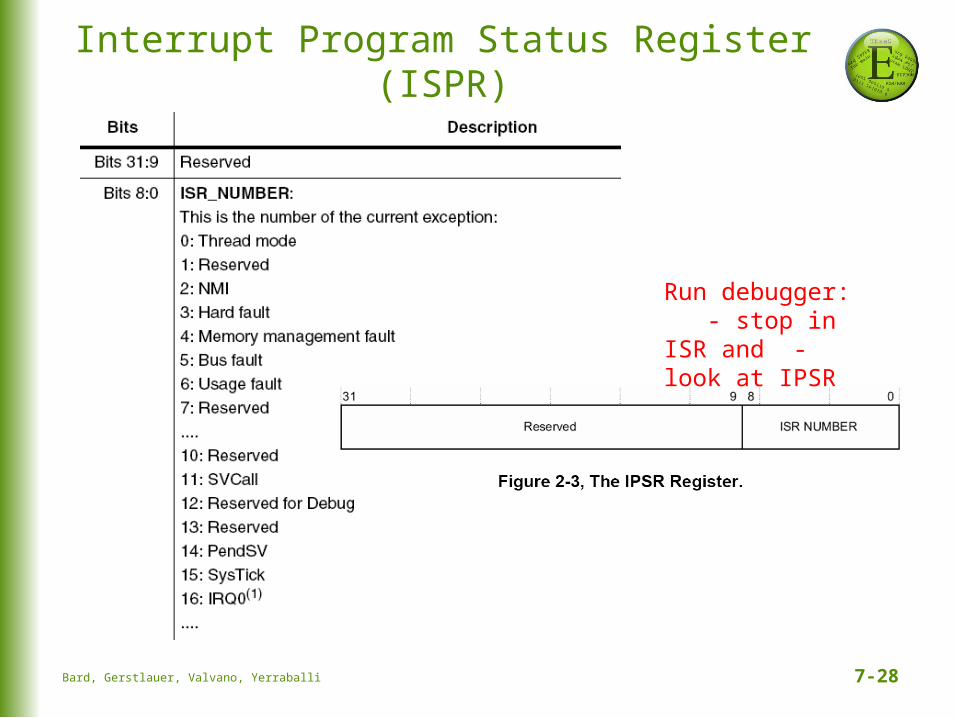
Interrupt Program Status Register (ISPR)
Run debugger: - stop in ISR and - look at IPSR
Bard, Gerstlauer, Valvano, Yerraballi
7-29
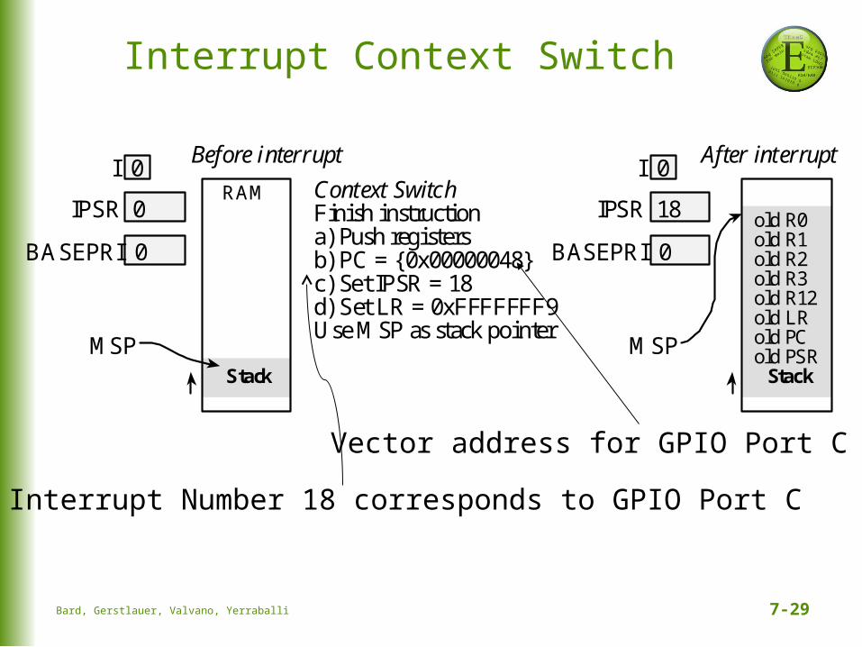
Interrupt Number 18 corresponds to GPIO Port C
Vector address for GPIO Port C
Interrupt Context Switch
Bard, Gerstlauer, Valvano, Yerraballi
old R0old R1old R2old R3old R12old LRold PCold PSR
Context SwitchFinish instructiona) Push registersb) PC = {0x00000048}c) Set IPSR = 18d) Set LR = 0xFFFFFFF9Use MSP as stack pointer
Before interrupt
RAM
Stack
I 0
IPSR 0
MSP
BASEPRI 0
After interrupt
Stack
I 0
IPSR 18
MSP
BASEPRI 0