Embed Size (px)
Citation preview
7-1
UNIT – IIITransmission Media & Switching
7-2
Transmission Media
• Guided Media • Unguided Media: Wireless
7-3
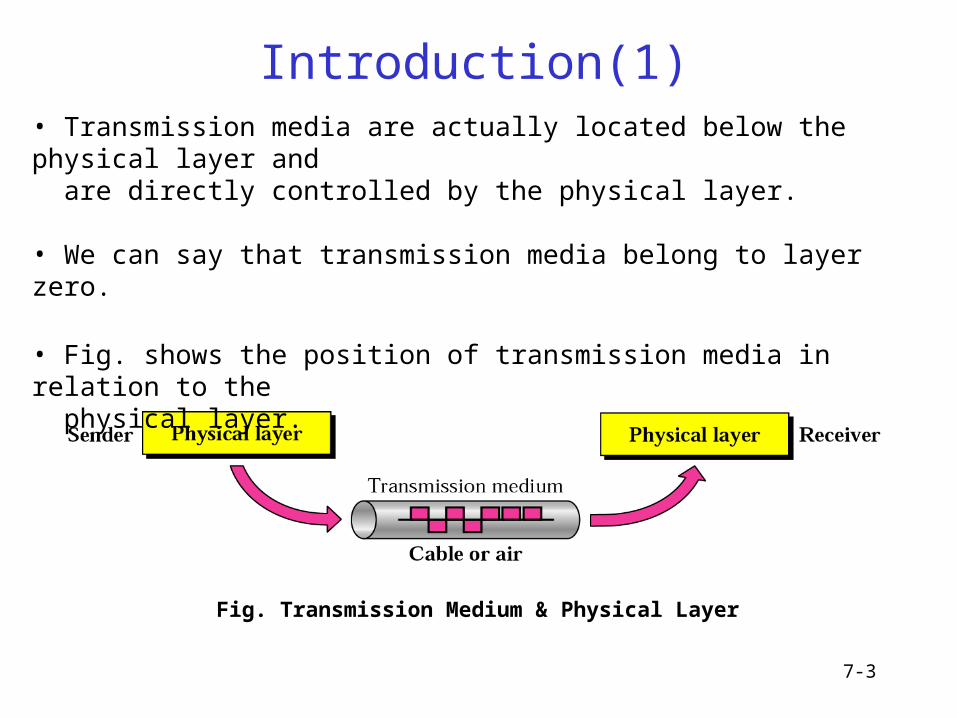
Introduction(1)
Fig. Transmission Medium & Physical Layer
• Transmission media are actually located below the physical layer and are directly controlled by the physical layer.
• We can say that transmission media belong to layer zero.
• Fig. shows the position of transmission media in relation to the physical layer.
Introduction(2)
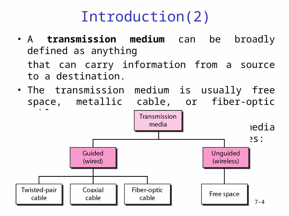
• A transmission medium can be broadly defined as anything
that can carry information from a source to a destination.
• The transmission medium is usually free space, metallic cable, or fiber-optic cable.
• In telecommunications, transmission media can be divided into two broad categories:
7-4
7-5
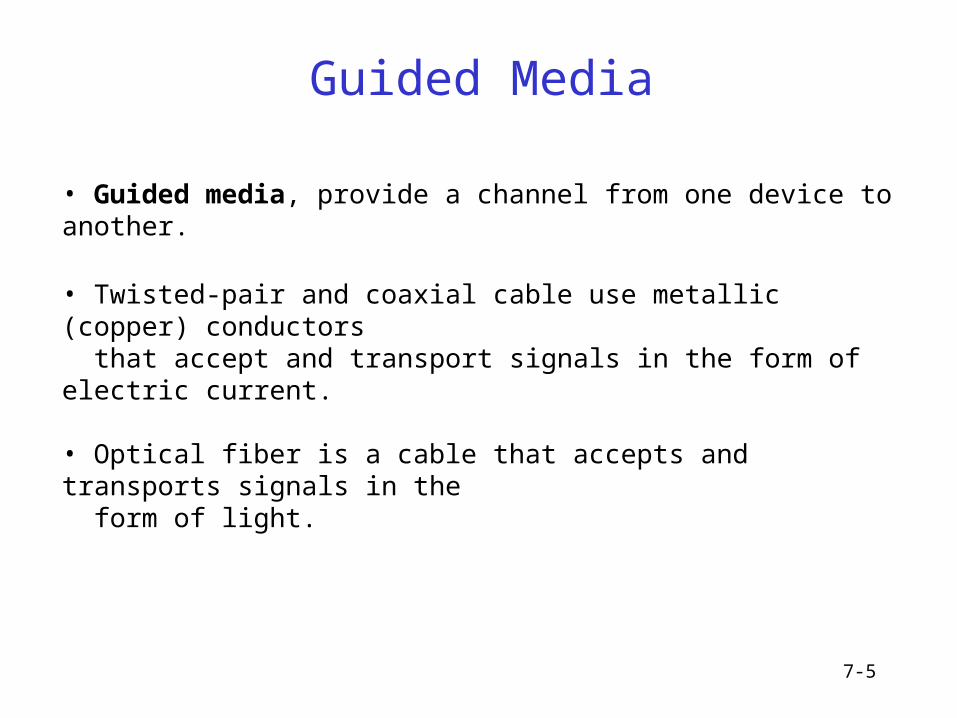
Guided Media
• Guided media, provide a channel from one device to another.
• Twisted-pair and coaxial cable use metallic (copper) conductors that accept and transport signals in the form of electric current.
• Optical fiber is a cable that accepts and transports signals in the form of light.
7-6
Guided Media - TPC
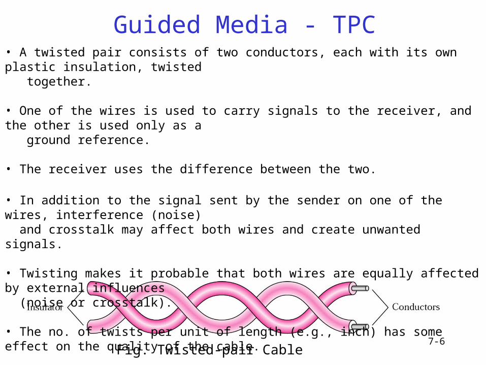
Fig. Twisted-pair Cable
• A twisted pair consists of two conductors, each with its own plastic insulation, twisted together.
• One of the wires is used to carry signals to the receiver, and the other is used only as a ground reference.
• The receiver uses the difference between the two.
• In addition to the signal sent by the sender on one of the wires, interference (noise) and crosstalk may affect both wires and create unwanted signals.
• Twisting makes it probable that both wires are equally affected by external influences (noise or crosstalk).
• The no. of twists per unit of length (e.g., inch) has some effect on the quality of the cable.
7-7
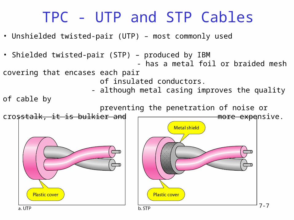
TPC - UTP and STP Cables• Unshielded twisted-pair (UTP) – most commonly used
• Shielded twisted-pair (STP) – produced by IBM - has a metal foil or braided mesh covering that encases each pair
of insulated conductors.- although metal casing improves the quality of cable by preventing the penetration of noise or crosstalk, it is bulkier and more expensive.
7-8
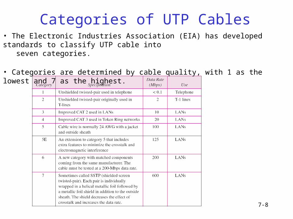
Categories of UTP Cables• The Electronic Industries Association (EIA) has developed standards to classify UTP cable into seven categories.
• Categories are determined by cable quality, with 1 as the lowest and 7 as the highest.
7-9
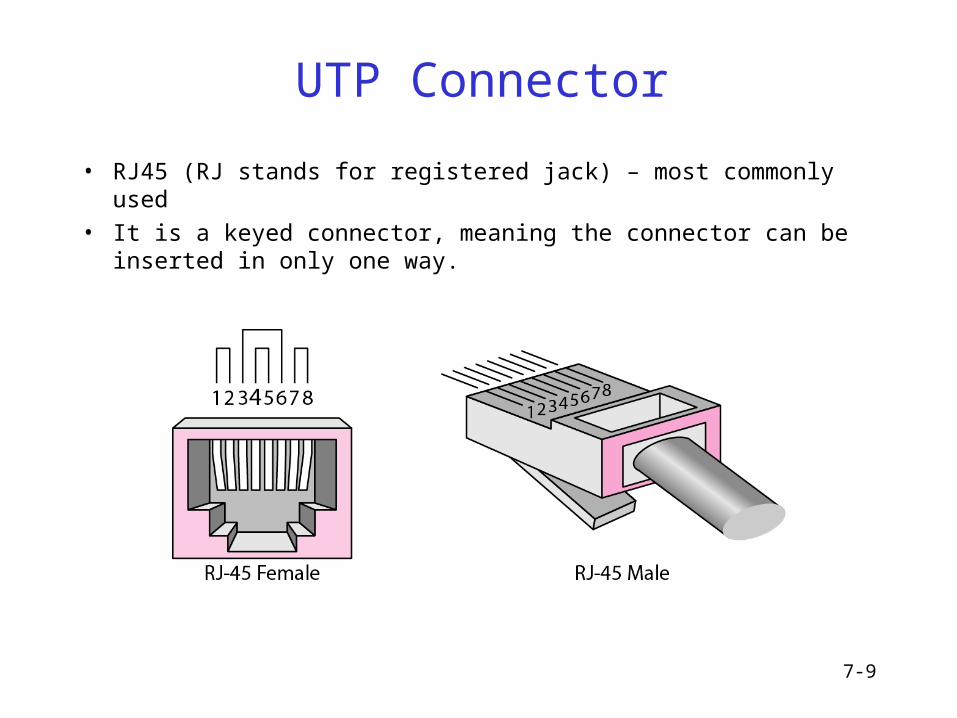
UTP Connector
• RJ45 (RJ stands for registered jack) – most commonly used
• It is a keyed connector, meaning the connector can be inserted in only one way.
7-10
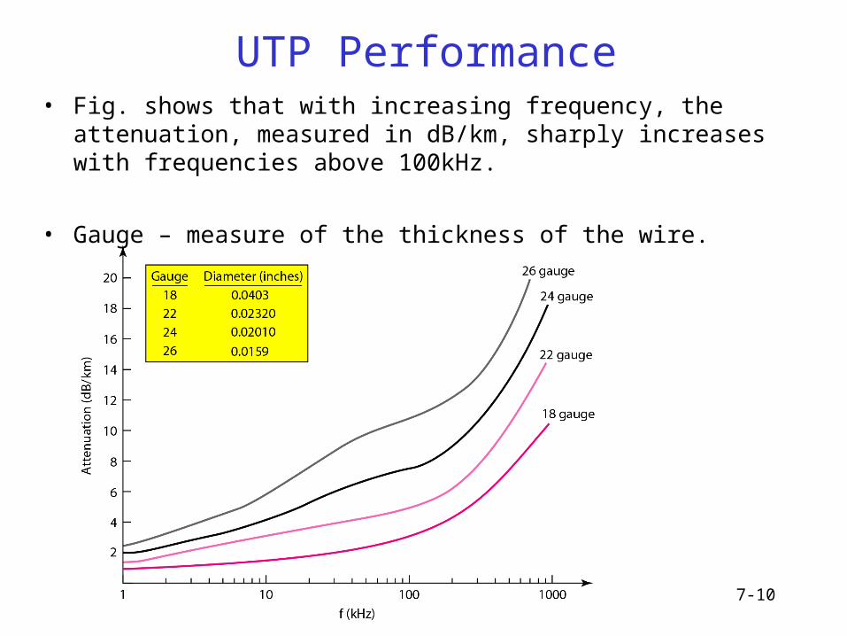
UTP Performance• Fig. shows that with increasing frequency, the attenuation, measured in
dB/km, sharply increases with frequencies above 100kHz.
• Gauge – measure of the thickness of the wire.
7-11
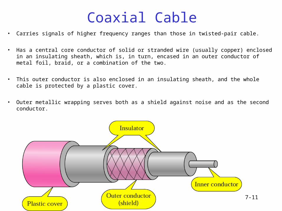
Coaxial Cable• Carries signals of higher frequency ranges than those in twisted-pair cable.
• Has a central core conductor of solid or stranded wire (usually copper) enclosed in an insulating sheath, which is, in turn, encased in an outer conductor of metal foil, braid, or a combination of the two.
• This outer conductor is also enclosed in an insulating sheath, and the whole cable is protected by a plastic cover.
• Outer metallic wrapping serves both as a shield against noise and as the second conductor.
7-12
Coaxial Cable Standards
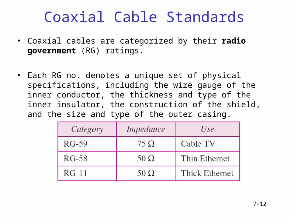
• Coaxial cables are categorized by their radio government (RG) ratings.
• Each RG no. denotes a unique set of physical specifications, including the wire gauge of the inner conductor, the thickness and type of the inner insulator, the construction of the shield, and the size and type of the outer casing.
7-13
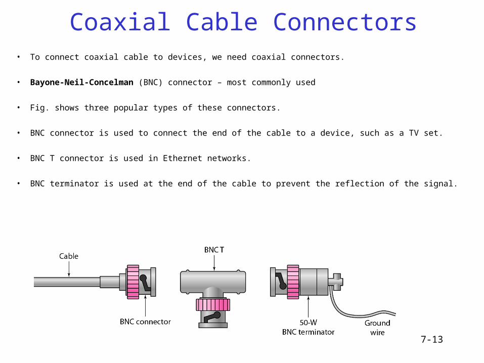
Coaxial Cable Connectors• To connect coaxial cable to devices, we need coaxial connectors.
• Bayone-Neil-Concelman (BNC) connector – most commonly used
• Fig. shows three popular types of these connectors.
• BNC connector is used to connect the end of the cable to a device, such as a TV set.
• BNC T connector is used in Ethernet networks.
• BNC terminator is used at the end of the cable to prevent the reflection of the signal.
7-14
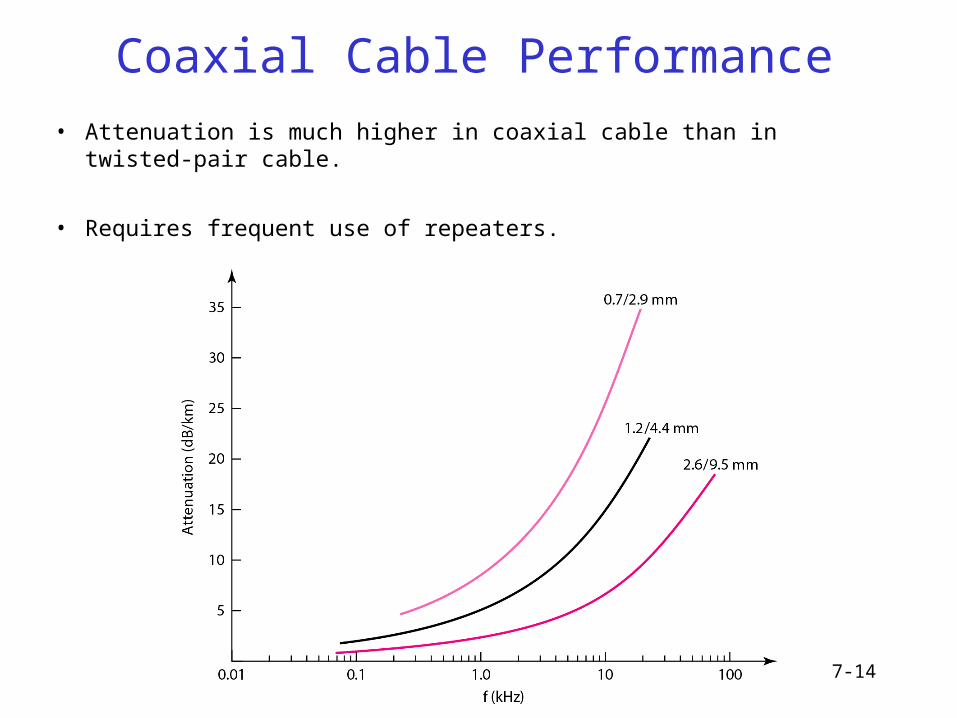
Coaxial Cable Performance
• Attenuation is much higher in coaxial cable than in twisted-pair cable.
• Requires frequent use of repeaters.
7-15
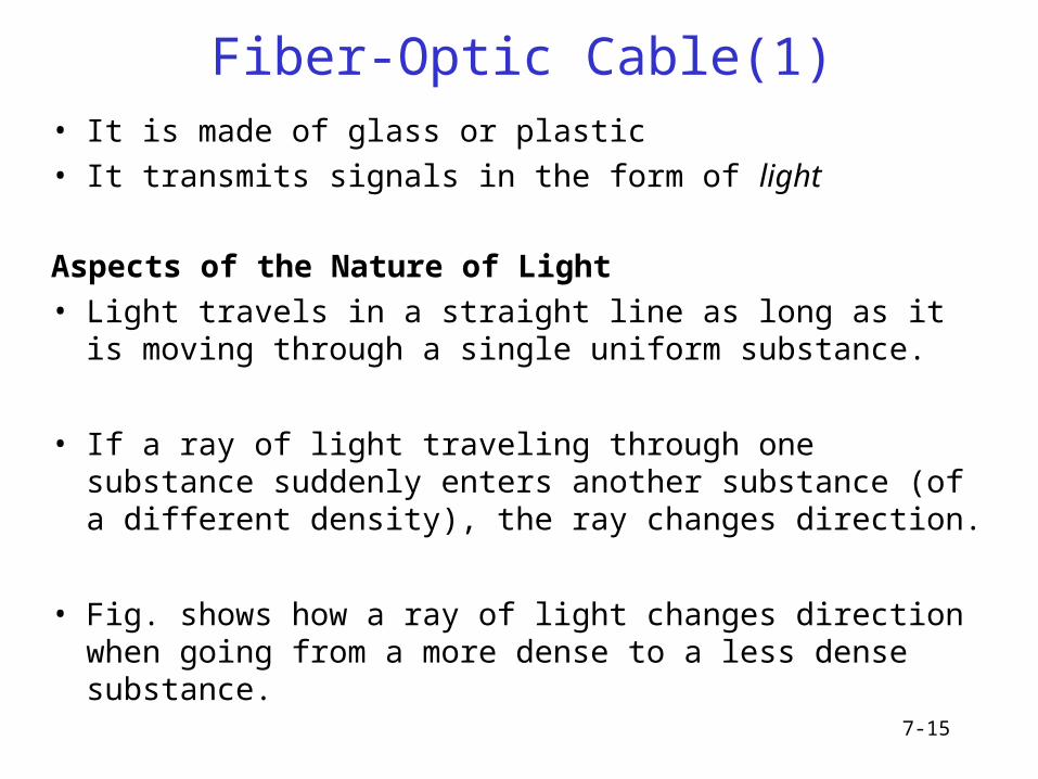
Fiber-Optic Cable(1)• It is made of glass or plastic
• It transmits signals in the form of light
Aspects of the Nature of Light
• Light travels in a straight line as long as it is moving through a single uniform substance.
• If a ray of light traveling through one substance suddenly enters another substance (of a different density), the ray changes direction.
• Fig. shows how a ray of light changes direction when going from a more dense to a less dense substance.
7-16
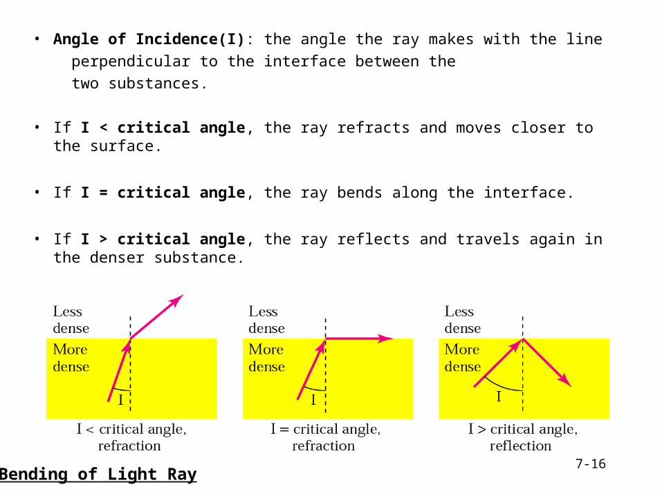
• Angle of Incidence(I): the angle the ray makes with the line
perpendicular to the interface between the
two substances.
• If I < critical angle, the ray refracts and moves closer to the surface.
• If I = critical angle, the ray bends along the interface.
• If I > critical angle, the ray reflects and travels again in the denser substance.
Bending of Light Ray
7-17
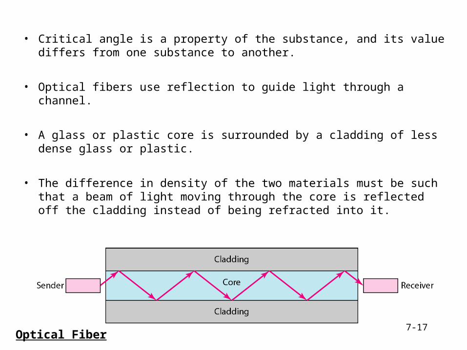
• Critical angle is a property of the substance, and its value differs from one substance to another.
• Optical fibers use reflection to guide light through a channel.
• A glass or plastic core is surrounded by a cladding of less dense glass or plastic.
• The difference in density of the two materials must be such that a beam of light moving through the core is reflected off the cladding instead of being refracted into it.
Optical Fiber
7-18
Fiber-Optic Cable(4)
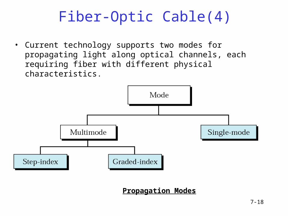
Propagation Modes
• Current technology supports two modes for propagating light along optical channels, each requiring fiber with different physical characteristics.
7-19
Fiber-Optic Cable(5)Multimode• Multiple beams from a light source move through the core in different paths.
• In multimode step-index fiber, the density of the core remains constant from the center to the edges.
• A beam of light moves through this constant density in a straight line until it reaches the interface of the core and cladding.
• At the interface, there is an abrupt change due to a lower density; this alters the angle of the beam’s motion.
• The term step index refers to the suddenness of this change, which distorts the signal as it passes through the fiber.
• The multimode graded-index fiber decreases this distortion.
• A graded-index fiber is one with varying densities, highest at the center of the core and decreases gradually to its lowest at the edge.
7-20
Fiber-Optic Cable(6)
Singlemode• Single-mode uses step-index fiber and a highly focused source of light.
• Single-mode fiber has a much smaller diameter than that of multimode fiber, and low density.
• The decrease in density results in a critical angle that is close enough to 900 to make the propagation of beams almost horizontal.
• In this case, propagation of different beams is almost identical, delays are negligible. All the beams arrive at the destination “together” and can be recombined with little distortion to the signal.

7-21
Modes
7-22
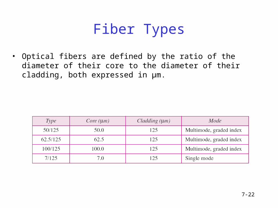
Fiber Types
• Optical fibers are defined by the ratio of the diameter of their core to the diameter of their cladding, both expressed in µm.
7-23
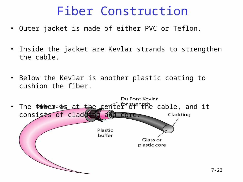
Fiber Construction• Outer jacket is made of either PVC or Teflon.
• Inside the jacket are Kevlar strands to strengthen the cable.
• Below the Kevlar is another plastic coating to cushion the fiber.
• The fiber is at the center of the cable, and it consists of cladding and core.
7-24
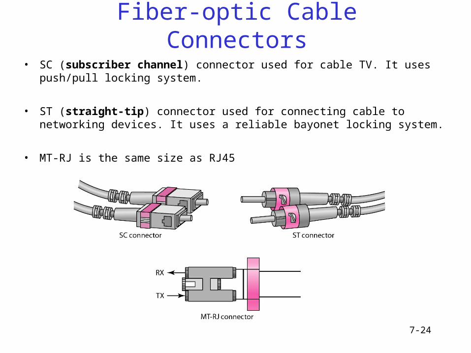
Fiber-optic Cable Connectors
• SC (subscriber channel) connector used for cable TV. It uses push/pull locking system.
• ST (straight-tip) connector used for connecting cable to networking devices. It uses a reliable bayonet locking system.
• MT-RJ is the same size as RJ45
7-25
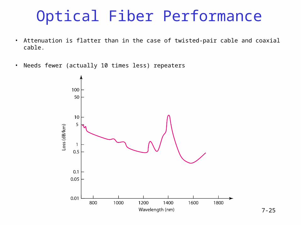
Optical Fiber Performance
• Attenuation is flatter than in the case of twisted-pair cable and coaxial cable.
• Needs fewer (actually 10 times less) repeaters
7-26
Applications of Optical Fiber
• Often found in backbone networks because its wide bandwidth is cost-effective.
- Cable TV
- LAN etc.
7-27
Advantages/Disadvantages of Optical Fiber
• Advantages– Higher bandwidth
– Less signal attenuation
– Immunity to electromagnetic interference
– Resistance to corrosive materials
– Light weight
– Greater immunity to tapping
• Disadvantages– Installation and maintenance
– Unidirectional light propagation
– Cost
7-28
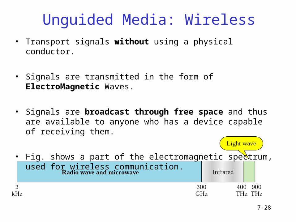
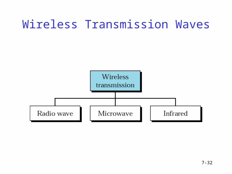
Unguided Media: Wireless• Transport signals without using a physical conductor.
• Signals are transmitted in the form of ElectroMagnetic Waves.
• Signals are broadcast through free space and thus are available to anyone who has a device capable of receiving them.
• Fig. shows a part of the electromagnetic spectrum, used for wireless communication.
7-29
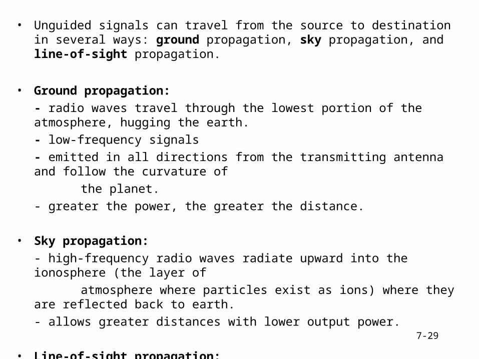
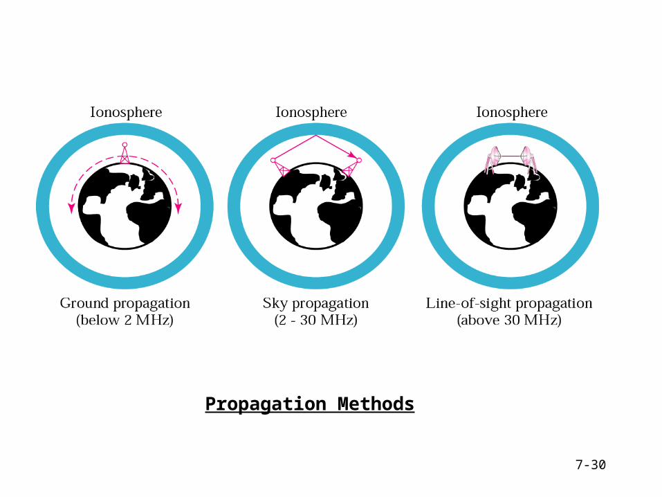
• Unguided signals can travel from the source to destination in several ways: ground propagation, sky propagation, and line-of-sight propagation.
• Ground propagation: - radio waves travel through the lowest portion of the atmosphere, hugging the earth. - low-frequency signals- emitted in all directions from the transmitting antenna and follow the curvature of
the planet.- greater the power, the greater the distance.
• Sky propagation: - high-frequency radio waves radiate upward into the ionosphere (the layer of
atmosphere where particles exist as ions) where they are reflected back to earth.
- allows greater distances with lower output power.
• Line-of-sight propagation: - Very high-frequency are transmitted in straight lines directly from antenna to antenna. - antennas must be directional, facing each other, and either tall enough or close enough together not to be affected by the curvature of the earth.
7-30
Propagation Methods

7-31
Bands
7-32
Wireless Transmission Waves
7-33
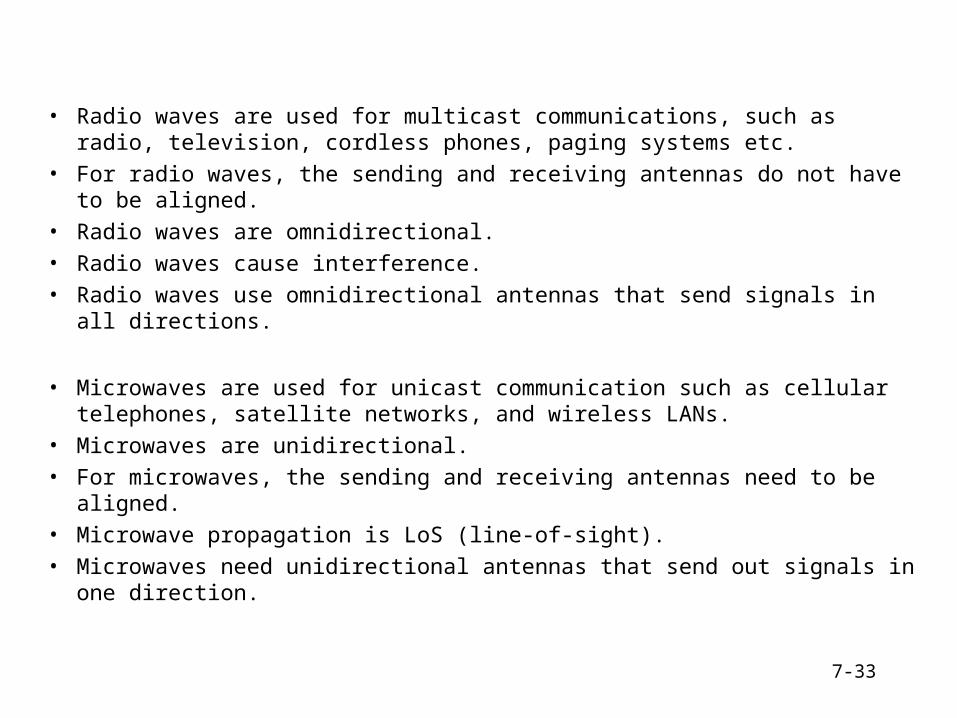
• Radio waves are used for multicast communications, such as radio, television, cordless phones, paging systems etc.
• For radio waves, the sending and receiving antennas do not have to be aligned.
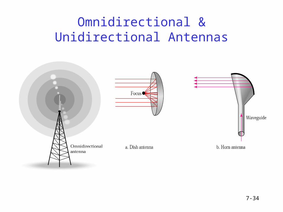
• Radio waves are omnidirectional.
• Radio waves cause interference.
• Radio waves use omnidirectional antennas that send signals in all directions.
• Microwaves are used for unicast communication such as cellular telephones, satellite networks, and wireless LANs.
• Microwaves are unidirectional.
• For microwaves, the sending and receiving antennas need to be aligned.
• Microwave propagation is LoS (line-of-sight).
• Microwaves need unidirectional antennas that send out signals in one direction.
7-34
Omnidirectional & Unidirectional Antennas
7-35
Infrared
• Infrared waves with frequencies from 300 GHz to 400 THz for short-range communication in a closed area using line-of-sight propagation
• Having high frequencies, it cannot penetrate walls
• IrDA (Infrared Data Association) for standards
• Example: IrDA port for wireless keyboard– Originally defined a data rate of 75 kbps for a distance up to 8 m
– Recent standard for a data rate of 4 Mbps
8-36
Switching
• Circuit-Switched Networks
• Datagram Networks
• Virtual-Circuit Networks
• Structure of a Switch
8-37
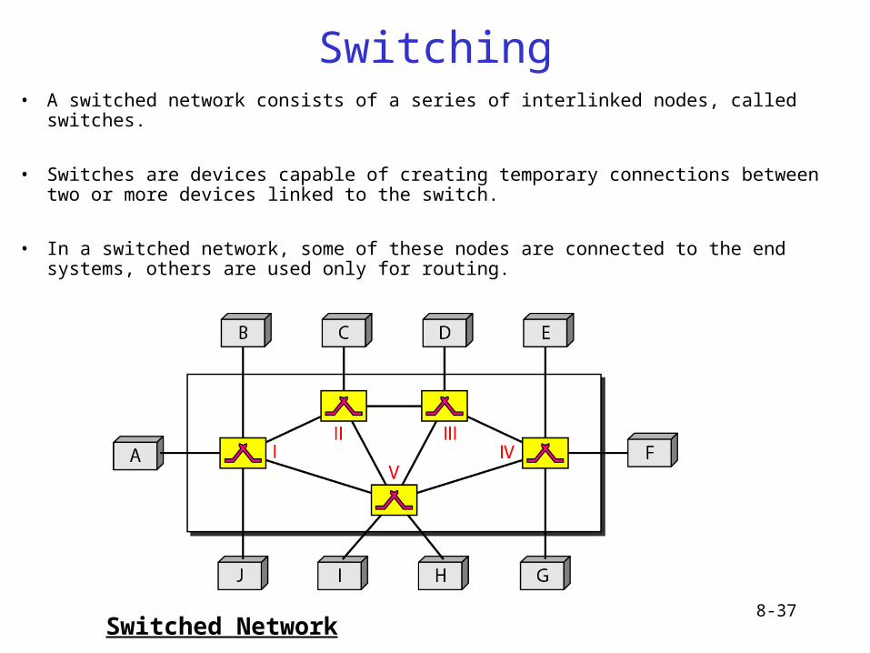
Switching• A switched network consists of a series of interlinked nodes, called switches.
• Switches are devices capable of creating temporary connections between two or more devices linked to the switch.
• In a switched network, some of these nodes are connected to the end systems, others are used only for routing.
Switched Network

8-38
Taxonomy of Switched Networks
• In message switching, each switch stores the whole message and forwards it to the next switch.
8-39
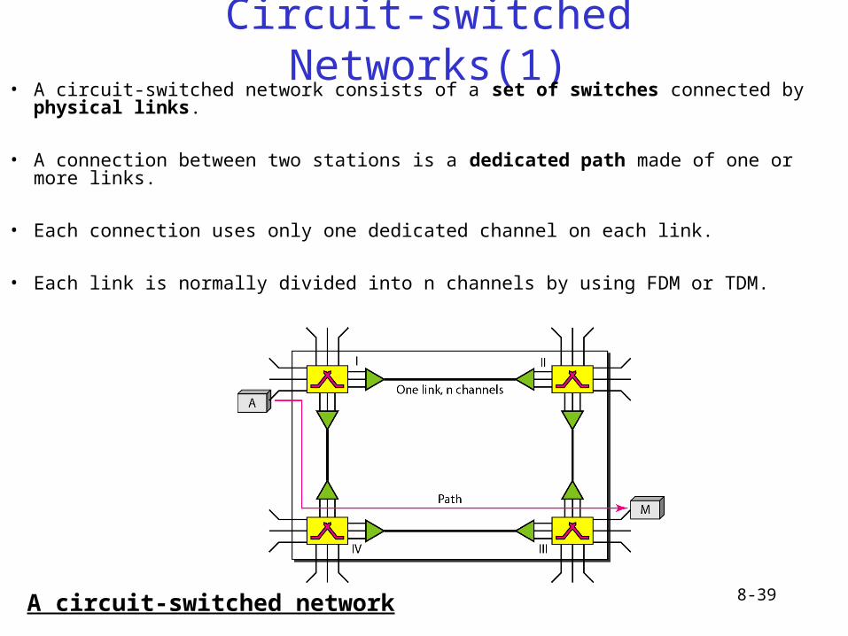
Circuit-switched Networks(1)• A circuit-switched network consists of a set of switches connected by physical links.
• A connection between two stations is a dedicated path made of one or more links.
• Each connection uses only one dedicated channel on each link.
• Each link is normally divided into n channels by using FDM or TDM.
A circuit-switched network
8-40
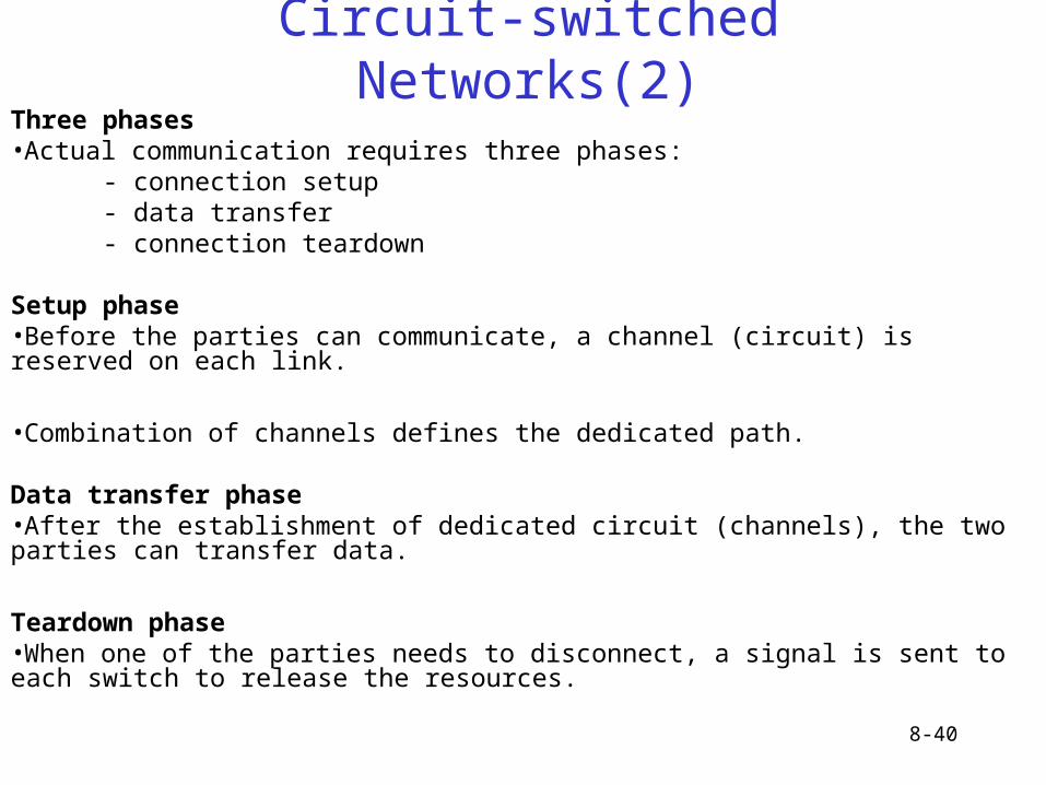
Circuit-switched Networks(2)Three phases•Actual communication requires three phases:
- connection setup- data transfer- connection teardown
Setup phase•Before the parties can communicate, a channel (circuit) is reserved on each link.
•Combination of channels defines the dedicated path.
Data transfer phase•After the establishment of dedicated circuit (channels), the two parties can transfer data.
Teardown phase•When one of the parties needs to disconnect, a signal is sent to each switch to release the resources.
8-41
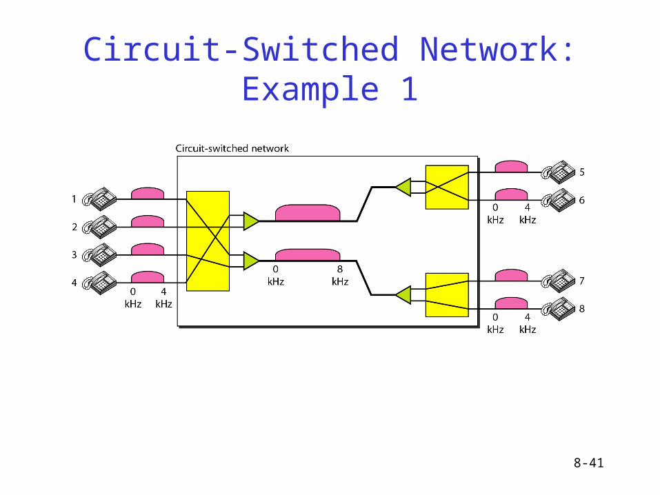
Circuit-Switched Network: Example 1
8-42
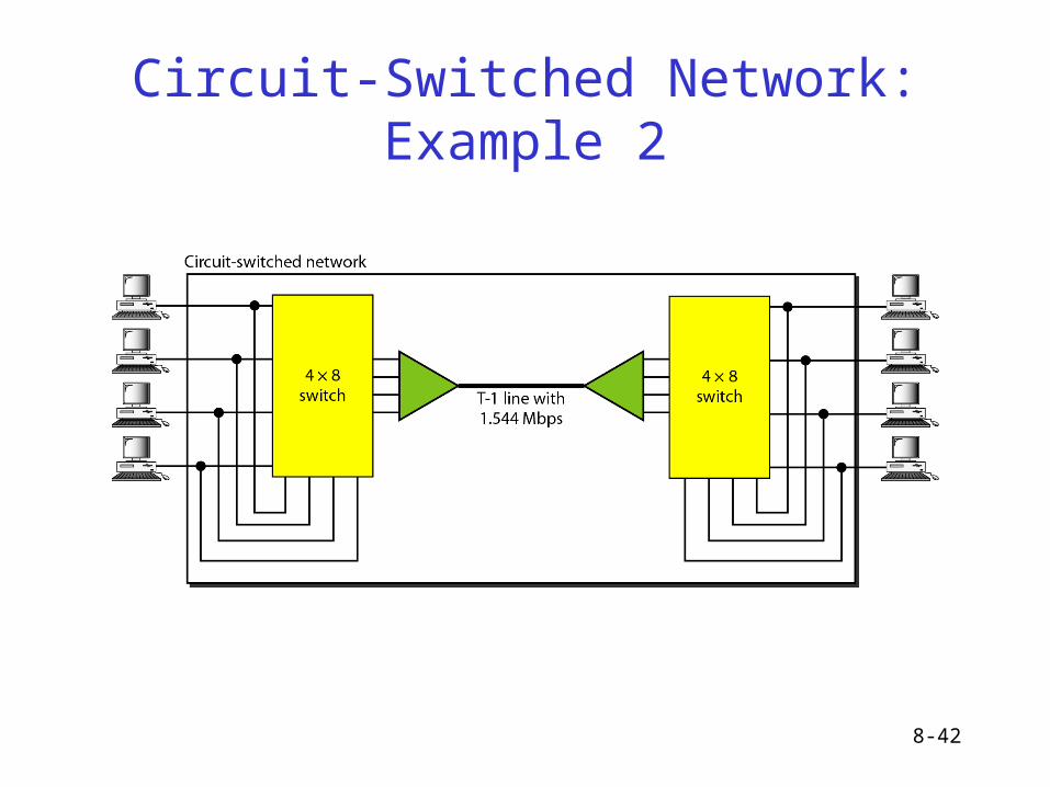
Circuit-Switched Network: Example 2
8-43
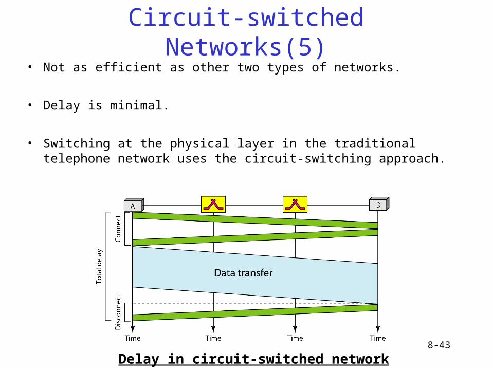
Circuit-switched Networks(5)• Not as efficient as other two types of networks.
• Delay is minimal.
• Switching at the physical layer in the traditional telephone network uses the circuit-switching approach.
Delay in circuit-switched network
8-44
Datagram Networks(1)
• In a packet-switched network, there is no resource allocation for a packet.
• Means that there is no reserved bandwidth on the links, and there is no scheduled processing time for each packet.
• Resources are allocated on demand.
• Allocation is done on a first-come, first served basis.
8-45
Datagram Networks(2)
• In a datagram network, each packet is treated independently of all others.• • Packets in this approach are referred to as datagrams.
• Switches in a datagram network are referred to as routers.
• Datagrams may arrive at their destination out of order.
• Datagrams may also be lost or dropped because of a lack of resources.
• Sometimes referred to as connectionless networks.
• Switching in the Internet is done by using datagram approach at the network layer.
8-46
Datagram Networks(3)
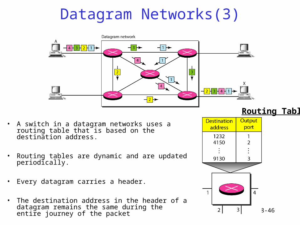
• A switch in a datagram networks uses a routing table that is based on the destination address.
• Routing tables are dynamic and are updated periodically.
• Every datagram carries a header.
• The destination address in the header of a datagram remains the same during the entire journey of the packet
Routing Table
8-47
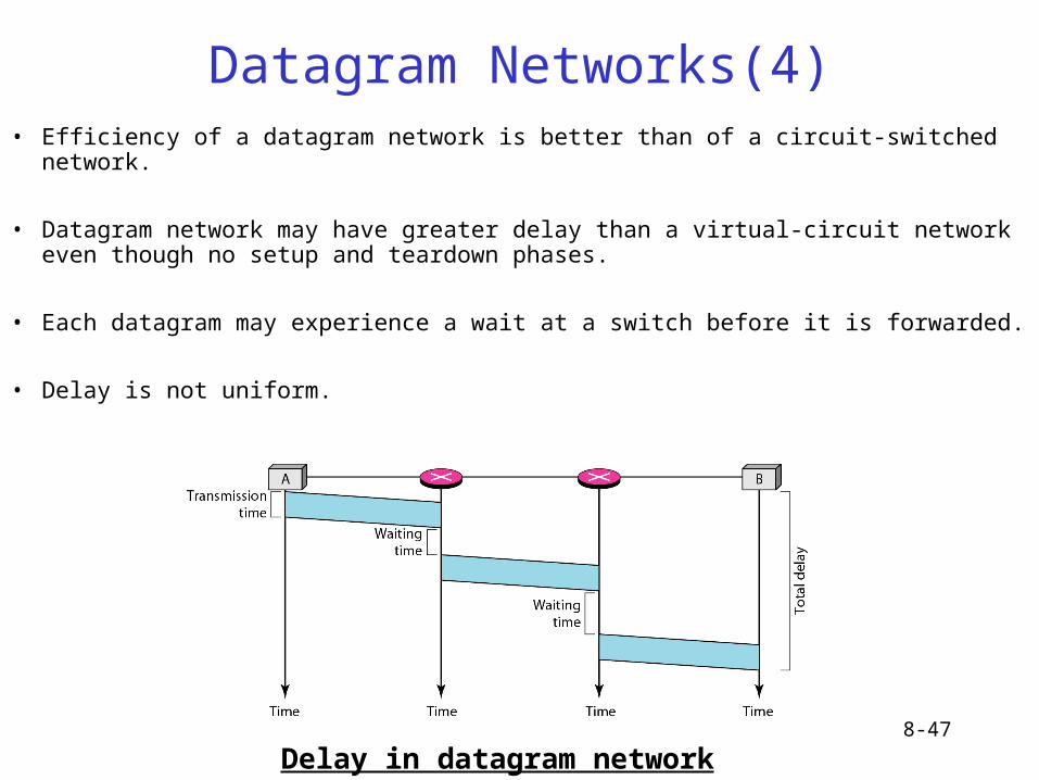
Datagram Networks(4)• Efficiency of a datagram network is better than of a circuit-switched network.
• Datagram network may have greater delay than a virtual-circuit network even though no setup and teardown phases.
• Each datagram may experience a wait at a switch before it is forwarded.
• Delay is not uniform.
Delay in datagram network
8-48
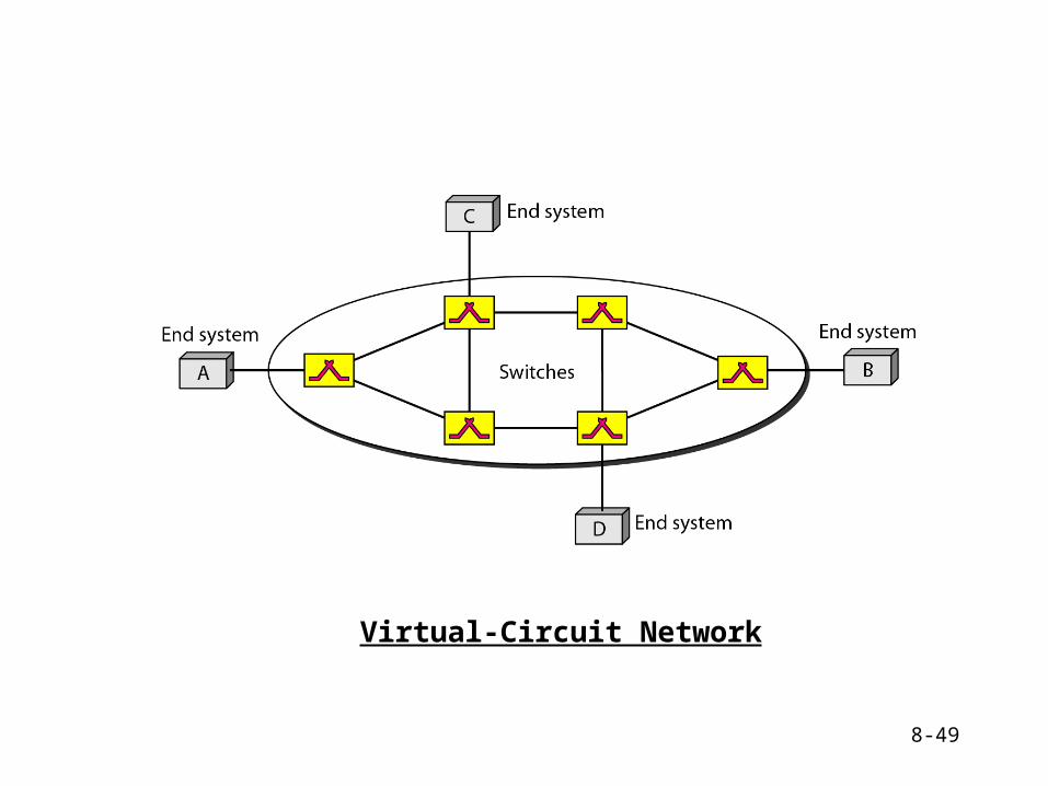
Virtual-Circuit Networks(1)
• A virtual-circuit network (VCN) is a cross between a circuit-switched network and a datagram network.
• It has some characteristics of both:- there are setup, data transfer, and teardown phases as in a circuit-
switched network (CSN)- resources can be allocated during setup phase, as in a CSN, or on
demand as in a datagram network (DN)- As in DN, data are packetized and each packet carries an address in
the header. This address is local i.e., it is the address of the next switch not the end system- As in CSN, all packets follow the same path established during the
connection- VCN is normally implemented in the data link layer, while CSN is in
physical layer and DN in the network layer
8-49
Virtual-Circuit Network
8-50
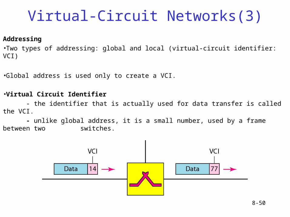
Virtual-Circuit Networks(3)
Addressing
•Two types of addressing: global and local (virtual-circuit identifier: VCI)
•Global address is used only to create a VCI.
•Virtual Circuit Identifier
- the identifier that is actually used for data transfer is called the VCI.
- unlike global address, it is a small number, used by a frame between two switches.
8-51
Virtual-Circuit Networks(4)
Three Phases
•Data transfer phase, setup phase, teardown phase
Data Transfer Phase
•To transfer a frame from S to its D, all switches need to have a table entry for this virtual-circuit.
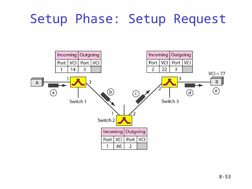
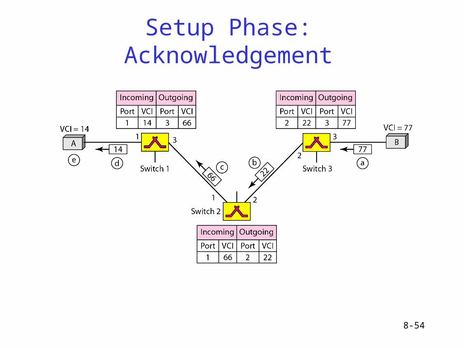
Setup Phase
•Switch creates an entry for a virtual-circuit.
•Two steps are required: the setup request and the acknowledgement.
Teardown Phase
•Two frames are exchanged: the teardown request and teardown confirmation.
Data transfer Phase
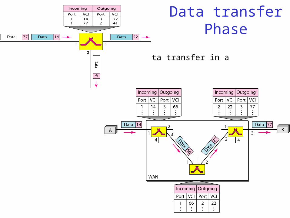
• Source-to-destination data transfer in a virtual-circuit network
8-52
8-53
Setup Phase: Setup Request
8-54
Setup Phase: Acknowledgement
8-55
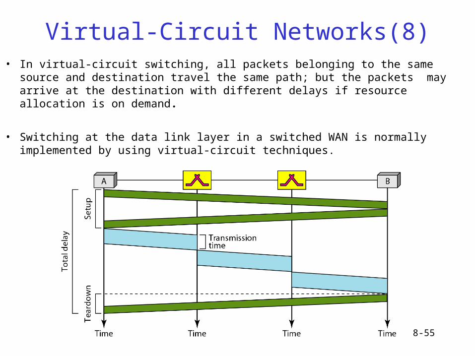
Virtual-Circuit Networks(8)• In virtual-circuit switching, all packets belonging to the same source and
destination travel the same path; but the packets may arrive at the destination with different delays if resource allocation is on demand.
• Switching at the data link layer in a switched WAN is normally implemented by using virtual-circuit techniques.
8-56
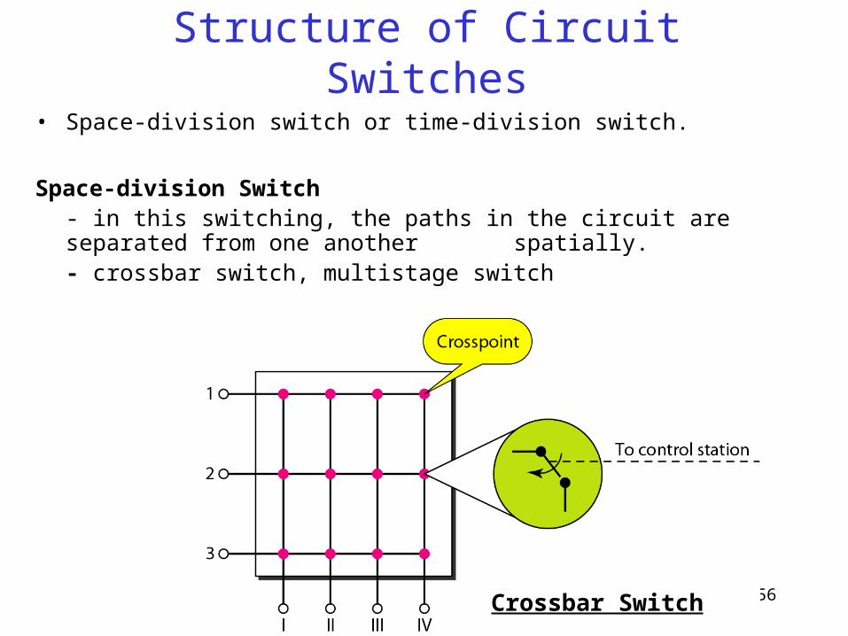
Structure of Circuit Switches
• Space-division switch or time-division switch.
Space-division Switch - in this switching, the paths in the circuit are separated from one
another spatially.- crossbar switch, multistage switch
Crossbar Switch

8-57
Crossbar Switches: Problem
• The number of switches is huge.– connect n inputs by m output -- requires n*m crosspoints.
– Ex : 1000 input, 1000 output → 1,000,000 crosspoint
• Inefficient– fewer than 25% of the crosspoints are in use at a given time.
8-58
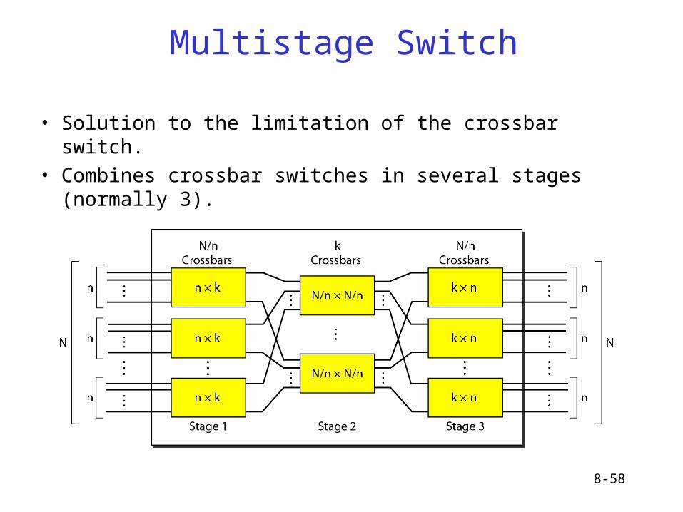
Multistage Switch
• Solution to the limitation of the crossbar switch.
• Combines crossbar switches in several stages (normally 3).
8-59
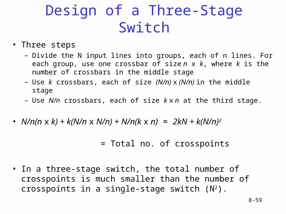
Design of a Three-Stage Switch
• Three steps– Divide the N input lines into groups, each of n lines. For each group, use
one crossbar of size n x k, where k is the number of crossbars in the middle stage
– Use k crossbars, each of size (N/n) x (N/n) in the middle stage
– Use N/n crossbars, each of size k x n at the third stage.
• N/n(n x k) + k(N/n x N/n) + N/n(k x n) = 2kN + k(N/n)2
= Total no. of crosspoints
• In a three-stage switch, the total number of crosspoints is much smaller than the number of crosspoints in a single-stage switch (N2).
8-60
Multistage Switch: Example 1
• Design a three-stage, 200 × 200 switch (N = 200) with k = 4 and n = 20.
• In the first stage we have N/n or 10 crossbars, each of size 20 × 4. In the second stage, we have 4 crossbars, each of size 10 × 10. In the third stage, we have 10 crossbars, each of size 4 × 20. The total number of crosspoints is 2kN + k(N/n)2, or 2000 crosspoints. This is 5 percent of the number of crosspoints in a single-stage switch (200 × 200 = 40,000).
8-61
Multistage Switches
• Advantage: The number of crosspoints.
• Disadvantage: blocking (Blocking refers to times when one input cannot be connected
to an output because there is no path available between them – all the possible intermediate switches are occupied.)
• Clos criterion: condition of nonblocking– n = (N/2)1/2
– k > 2n – 1– Crosspoints ≥ 4N [(2N)1/2 – 1]

8-62
Multistage Switch: Example 2
• Redesign the previous three-stage, 200 × 200 switch, using the Clos criteria with a minimum number of crosspoints.
.• We let n = (200/2)1/2, or n = 10. We calculate k = 2n − 1 = 19. In the
first stage, we have 200/10, or 20, crossbars, each with 10 × 19 crosspoints. In the second stage, we have 19 crossbars, each with 10 × 10 crosspoints. In the third stage, we have 20 crossbars each with 19 × 10 crosspoints. The total number of crosspoints is 20(10 × 19) + 19(10 × 10) + 20(19 ×10) = 9500.
8-63
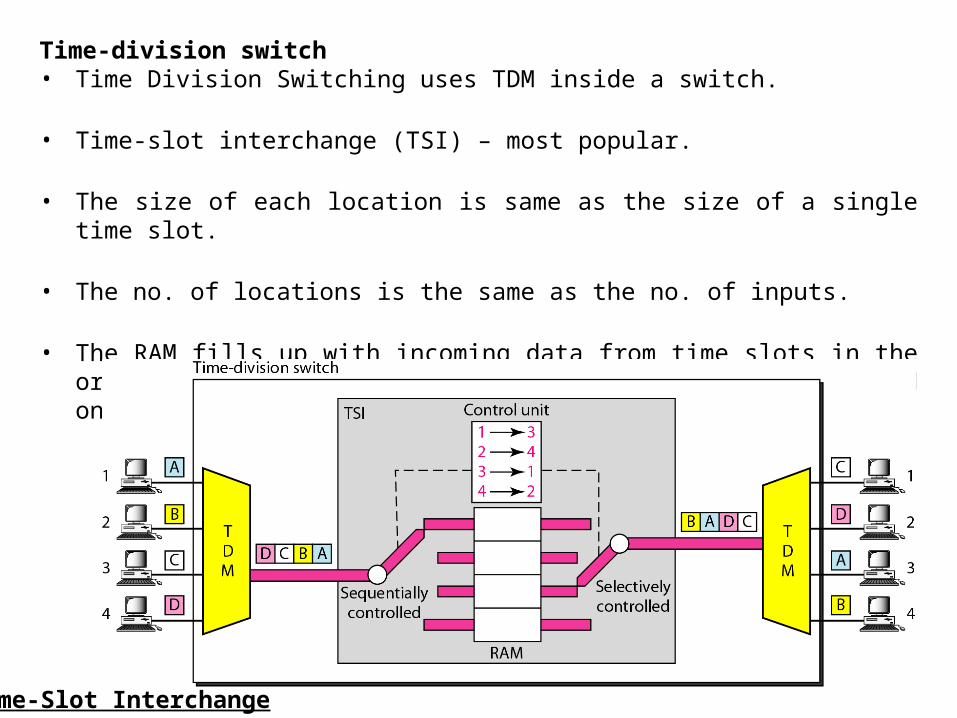
Time-division switch• Time Division Switching uses TDM inside a switch.
• Time-slot interchange (TSI) – most popular.
• The size of each location is same as the size of a single time slot.
• The no. of locations is the same as the no. of inputs.
• The RAM fills up with incoming data from time slots in the order received. Slots are then sent out in an order based on the decisions of a control unit.
Time-Slot Interchange
8-64
Time- and Space-Division Switch Combinations
• Advantage of space division switching is that it is instantaneous, requires more no. of crosspoints.
• Advantage of time division switching is that it needs more no crosspoints, but introduces delay.
• To take advantage of best of both, combine space-division and time-division technologies.
• Fig. shows a simple time-space-time (TST) switch that consists of two time stages and one space stage.
• Last stage is a mirror image of the first stage.
• Middle stage is a space-division switch (crossbar) that connects the TSI groups to allow connectivity between all possible input and output pairs.

8-65
TST Switch
8-66
Structure of Packet Switches
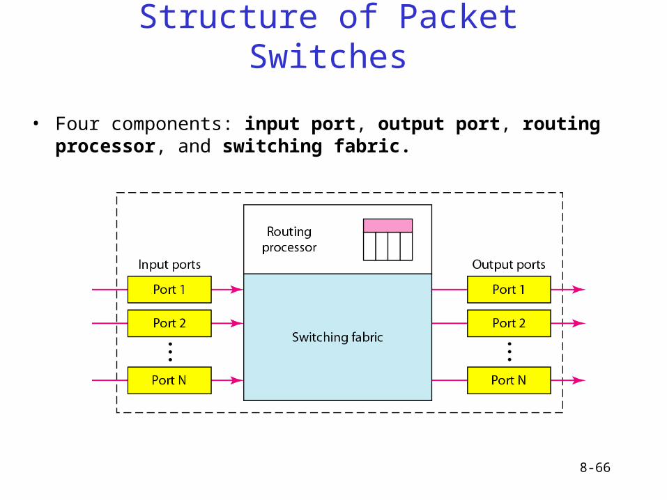
• Four components: input port, output port, routing processor, and switching fabric.

8-67
Structure of Packet Switches(2)
INPUT PORTS
• Perform physical and data link functions.
• Bits are constructed from the received signal.
• Packet is decapsulated from the frame.
• Errors are detected and corrected.
• In addition to physical layer processor and a data link processor, the input port has buffers (queues) to hold the packet before it is directed to the switching fabric.
8-68
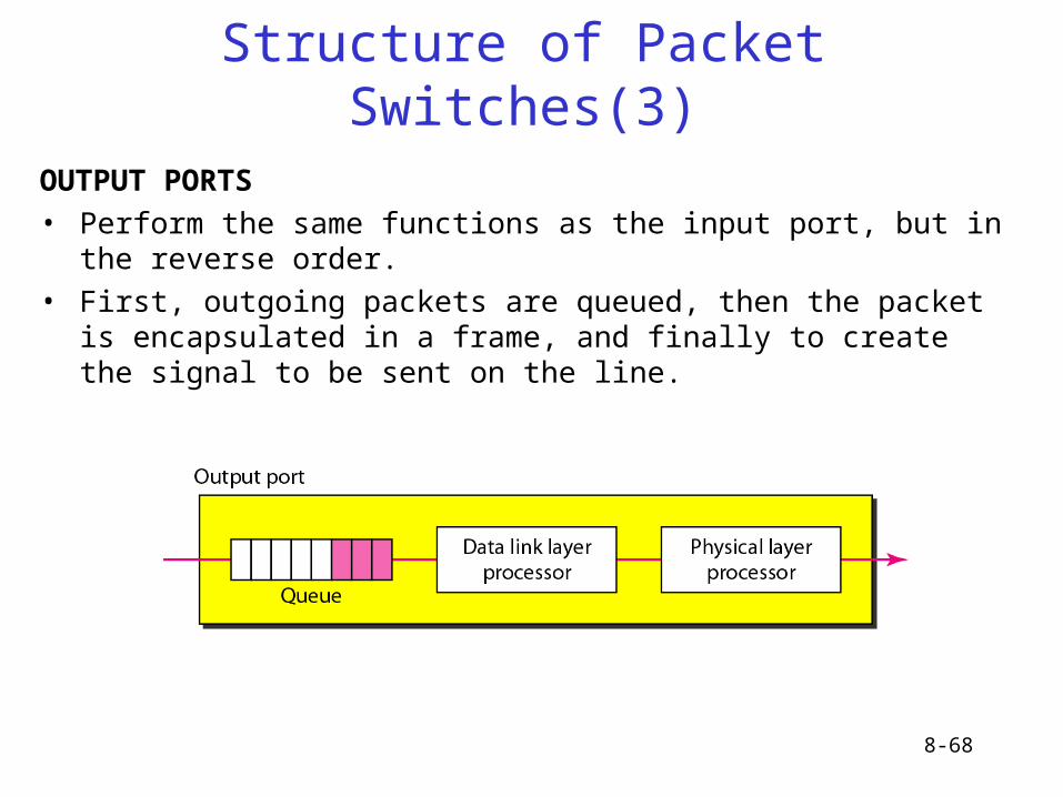
Structure of Packet Switches(3)
OUTPUT PORTS
• Perform the same functions as the input port, but in the reverse order.
• First, outgoing packets are queued, then the packet is encapsulated in a frame, and finally to create the signal to be sent on the line.
8-69
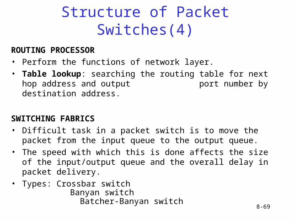
Structure of Packet Switches(4)
ROUTING PROCESSOR• Perform the functions of network layer.• Table lookup: searching the routing table for next hop address and output
port number by destination address.
SWITCHING FABRICS• Difficult task in a packet switch is to move the packet from the input queue to
the output queue. • The speed with which this is done affects the size of the input/output queue
and the overall delay in packet delivery.• Types: Crossbar switch
Banyan switch Batcher-Banyan switch
8-70
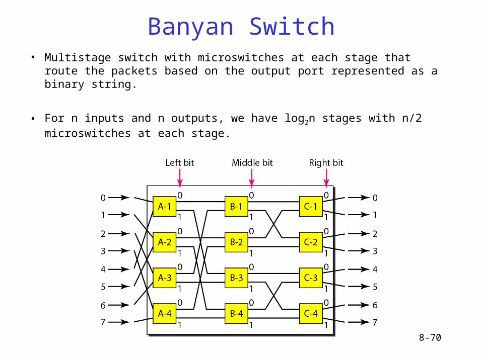
Banyan Switch• Multistage switch with microswitches at each stage that route the packets
based on the output port represented as a binary string.
• For n inputs and n outputs, we have log2n stages with n/2 microswitches at each stage.
8-71
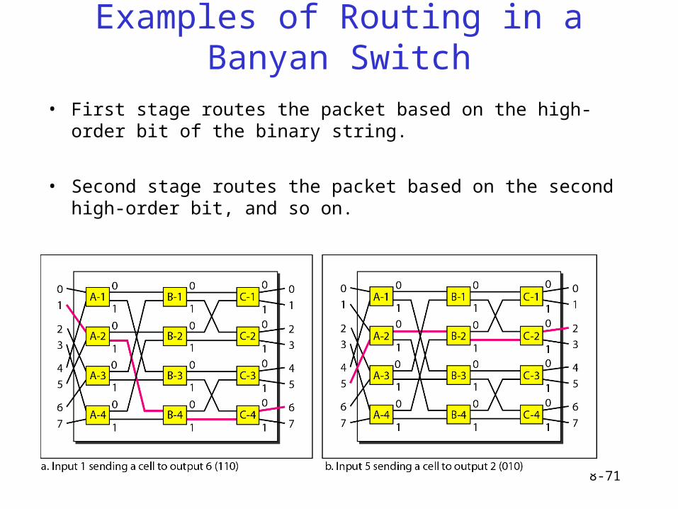
Examples of Routing in a Banyan Switch
• First stage routes the packet based on the high-order bit of the binary string.
• Second stage routes the packet based on the second high-order bit, and so on.
8-72
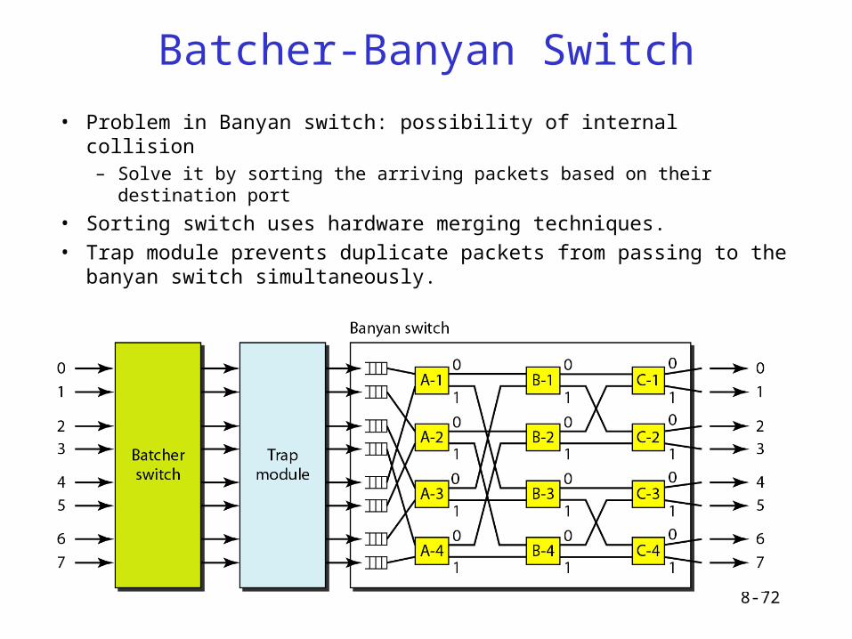
Batcher-Banyan Switch
• Problem in Banyan switch: possibility of internal collision– Solve it by sorting the arriving packets based on their destination port
• Sorting switch uses hardware merging techniques.
• Trap module prevents duplicate packets from passing to the banyan switch simultaneously.