Embed Size (px)
Citation preview

7 CAPELLA COURT, OTTAWA, ON K2E 8A7, CANADA | TEL (613) 736-4077 | FAX (613) 736-4071 | WWW.LUMENERA.COM | [email protected]
© 2017 Lumenera Corporation. All rights reserved.
Design, features, and specifications are subject to change without notice i
09282017

7 CAPELLA COURT, OTTAWA, ON K2E 8A7, CANADA | TEL (613) 736-4077 | FAX (613) 736-4071 | WWW.LUMENERA.COM | [email protected]
© 2017 Lumenera Corporation. All rights reserved.
Design, features, and specifications are subject to change without notice ii
09282017
7 CAPELLA COURT, OTTAWA, ON K2E 8A7, CANADA | TEL (613) 736-4077 | FAX (613) 736-4071 | WWW.LUMENERA.COM | [email protected]
© 2017 Lumenera Corporation. All rights reserved.
Design, features, and specifications are subject to change without notice i
09282017
WWW.LUMENERA.COM
Lumenera Camera User's Manual
Release 6.8.1
License Agreement (Software):
This Agreement states the terms and conditions upon which Lumenera Corporation ("Lumenera") offers to license to you (the "Licensee") the software together with all related documentation and accompanying items including, but not limited to, the executable programs, drivers, libraries, and data files associated with such programs (collectively, the "Software").
The Software is licensed, not sold, to you for use only under the terms of this Agreement.
Lumenera grants to you the right to use all or a portion of this Software provided that the Software is used only in conjunction with Lumenera's family of products.
In using the Software you agree not to:
a) Decompile, disassemble, reverse engineer, or otherwise attempt to derive the source code for any Product (except to the extent applicable laws specifically prohibit such restriction);
b) Remove or obscure any trademark or copyright notices.
Limited Warranty (Hardware and Software):
Any use of the software or hardware is at your own risk. The software is provided for use only with Lumenera’s hardware and other related software. The Software is provided for use as is without warranty of any kind to the maximum extent permitted by law, Lumenera disclaims all warranties of any kind, either expressed or implied, including, without limitation, implied warranties or conditions of merchantability, quality and fitness for a particular purpose. Lumenera is not obligated to provide any updates or upgrades to the software or purpose. Lumenera is not obligated to provide any updates or upgrades to the software or any related hardware.
Limited Liability (Hardware and Software):
In no event shall Lumenera or its Licensor's be liable for any damages whatsoever (including, without limitation, incidental, direct, indirect, special or consequential damages, damages for loss of business profits, business interruption, loss of business information, or other pecuniary loss) arising out of the use or inability to use this Software or related Hardware, including, but not limited to, any of Lumenera's family of products.
Warning
This unit is for use only with compatible UL listed devices. If the unit is powered via an external power adapter, the powered adapter shall be UL listed with LPS output.
Product Warranty
Unless existing agreements are in place that specify alternate warranty periods, Lumenera Corporation (‘Lumenera’) warrants to the original purchaser that the cameras shall be free from material and manufacturing defects (‘Warranty’) for a (‘Warranty Period’) stated in Lumenera Warranty Policy on our website at [www.lumenera.com/support/warranty-information.html].
Should the unit fail during the warranty period, Lumenera will, at its option, repair or replace the failed unit. Repaired or replaced units will be covered under warranty for the remainder of the original warranty period.
This warranty does not apply to units that, after being inspected by Lumenera, have been found to have failed due to customer abuse, accidents, mishandling, tampering/alteration, improper installation, improper power source, negligence, opening of the enclosure, or if the serial number has been removed or damaged. This warranty does not cover labour or incurred charges required in removing or installing the unit, any business interruption, loss of profits/revenues, or any consequential damages.
Units returned to Lumenera beyond the warranty period will be repaired, if possible, and all appropriate material and labour charges will apply.
Any returning product, specifically those being returned under warranty, must follow the Returned Material Authorization (RMA) process. Any units being returned are to be properly packaged (in original packing – if possible). Lumenera will not cover damage sustained in shipping due to improper packing.
For RMA instructions please refer to our website at [www.lumenera.com/support/rma.php].
7 CAPELLA COURT, OTTAWA, ON K2E 8A7, CANADA | TEL (613) 736-4077 | FAX (613) 736-4071 | WWW.LUMENERA.COM | [email protected]
© 2017 Lumenera Corporation. All rights reserved.
Design, features, and specifications are subject to change without notice ii
09282017
WWW.LUMENERA.COM
Lumenera Camera User's Manual
Release 6.8.1
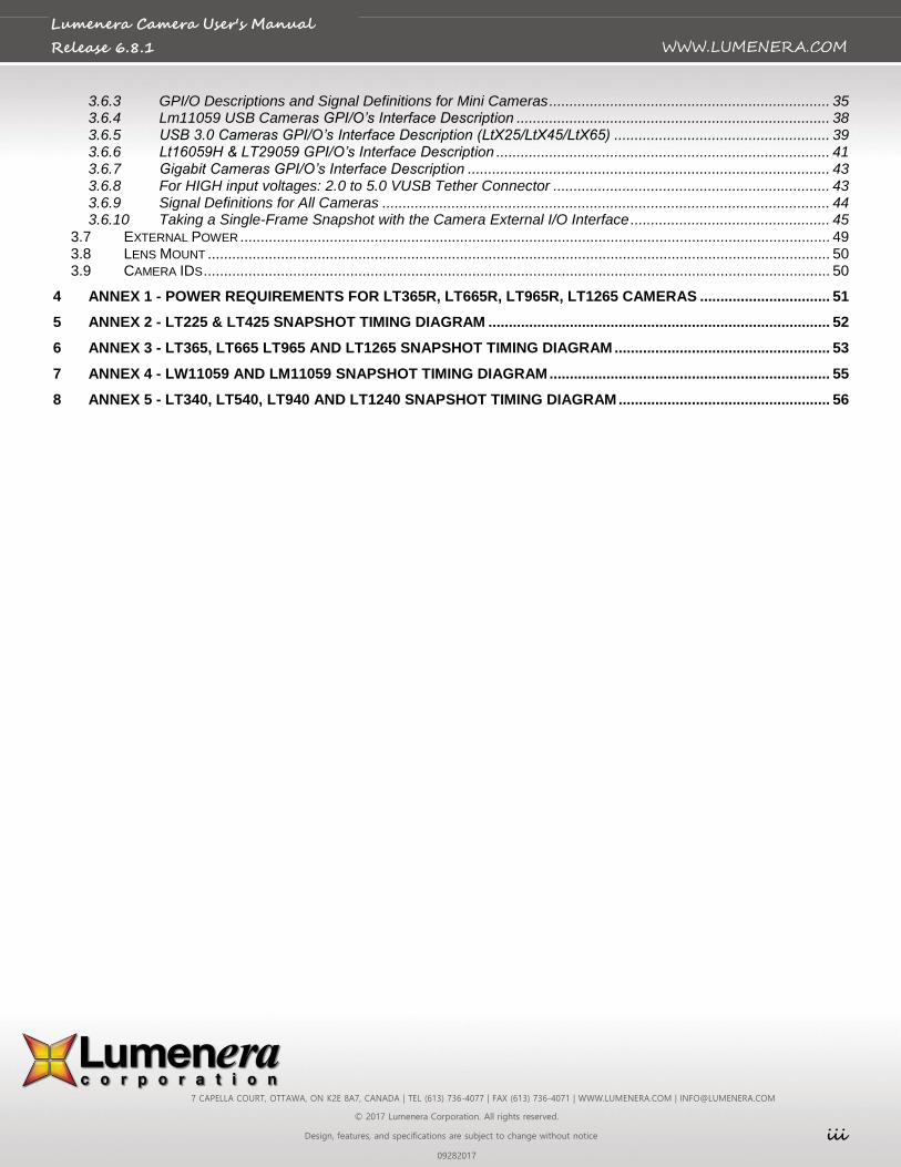
Table of Contents
TABLE OF CONTENTS ............................................................................................................................................................. II
1 INTRODUCTION ............................................................................................................................................................ 4
1.1 THE LUMENERA USB AND GIGE CAMERA FAMILY ...................................................................................................... 4
2 INSTALLING AND USING THE CAMERA.................................................................................................................... 5
2.2 CAMERA AND SOFTWARE INSTALLATION .................................................................................................................... 5 2.2.1 Minimum System Requirements ................................................................................................................... 5 2.2.2 Camera Power Requirements ....................................................................................................................... 5 2.2.3 Camera LED indicator ................................................................................................................................... 5 2.2.4 USB Camera Installation Procedure ............................................................................................................. 6 2.2.5 GigE Cameras Installation Procedure ......................................................................................................... 11 2.2.6 USB Plug-and-Play Device Recognition ..................................................................................................... 16 2.2.7 Software Upgrade Procedure ..................................................................................................................... 16 2.2.8 USB Camera Troubleshooting .................................................................................................................... 16
2.3 TECHNICAL ASSISTANCE ......................................................................................................................................... 19 2.4 USING THE INSTALLED SOFTWARE .......................................................................................................................... 19
2.4.1 Drivers & INF ............................................................................................................................................... 19 2.4.2 DirectShow Filters ....................................................................................................................................... 19 2.4.3 Application Software ................................................................................................................................... 20 2.4.4 Sample Application Executables ................................................................................................................. 20 2.4.5 Software Development Kit (SDK) ................................................................................................................ 20 2.4.6 Documentation ............................................................................................................................................ 21 2.4.7 Driver Only Installation Packages ............................................................................................................... 21
2.5 USING LUCAM & LGCAM CAPTURE ......................................................................................................................... 22 2.5.1 Buttons and Interface Controls ................................................................................................................... 22 2.5.2 Dialog Items ................................................................................................................................................ 23 2.5.3 View Menu Items ......................................................................................................................................... 23 2.5.4 Options Menu Items .................................................................................................................................... 24 2.5.5 Lens Control section ................................................................................................................................... 24 2.5.6 Snapshot Settings ....................................................................................................................................... 24
3 UNDERSTANDING YOUR CAMERA .......................................................................................................................... 26
3.1 SHUTTER TYPES AND SCANNING MODE ................................................................................................................... 26 3.1.1 Rolling Shutter ............................................................................................................................................. 26 3.1.2 Half Global Shutter ...................................................................................................................................... 26 3.1.3 Global Shutter ............................................................................................................................................. 26 3.1.4 Progressive Scan Mode .............................................................................................................................. 27
3.2 USE OF FLASH OR STROBE ..................................................................................................................................... 28 3.2.1 Flash with Rolling Shutter ........................................................................................................................... 28 3.2.2 Flash with Half Global Shutter .................................................................................................................... 28 3.2.3 Flash with Global Shutter ............................................................................................................................ 28
3.3 CAMERA MODES .................................................................................................................................................... 28 3.3.1 Streaming Video .......................................................................................................................................... 28 3.3.2 Snapshot (still mode) .................................................................................................................................. 28
3.4 DATA FORMAT ....................................................................................................................................................... 29 3.5 SUBWINDOWING, SUBSAMPLING & BINNING ............................................................................................................. 32 3.6 EXTERNAL I/O INTERFACE ...................................................................................................................................... 32
3.6.1 Standard LuCam Camera GPI/O Interface Description .............................................................................. 32 3.6.2 LuCam Large Format LW1X05X Camera GPI/O Interface Description ..................................................... 34
7 CAPELLA COURT, OTTAWA, ON K2E 8A7, CANADA | TEL (613) 736-4077 | FAX (613) 736-4071 | WWW.LUMENERA.COM | [email protected]
© 2017 Lumenera Corporation. All rights reserved.
Design, features, and specifications are subject to change without notice iii
09282017
WWW.LUMENERA.COM
Lumenera Camera User's Manual
Release 6.8.1
3.6.3 GPI/O Descriptions and Signal Definitions for Mini Cameras ..................................................................... 35 3.6.4 Lm11059 USB Cameras GPI/O’s Interface Description ............................................................................. 38 3.6.5 USB 3.0 Cameras GPI/O’s Interface Description (LtX25/LtX45/LtX65) ..................................................... 39 3.6.6 Lt16059H & LT29059 GPI/O’s Interface Description .................................................................................. 41 3.6.7 Gigabit Cameras GPI/O’s Interface Description ......................................................................................... 43 3.6.8 For HIGH input voltages: 2.0 to 5.0 VUSB Tether Connector .................................................................... 43 3.6.9 Signal Definitions for All Cameras .............................................................................................................. 44 3.6.10 Taking a Single-Frame Snapshot with the Camera External I/O Interface ................................................. 45
3.7 EXTERNAL POWER ................................................................................................................................................. 49 3.8 LENS MOUNT ......................................................................................................................................................... 50 3.9 CAMERA IDS .......................................................................................................................................................... 50
4 ANNEX 1 - POWER REQUIREMENTS FOR LT365R, LT665R, LT965R, LT1265 CAMERAS ................................ 51
5 ANNEX 2 - LT225 & LT425 SNAPSHOT TIMING DIAGRAM .................................................................................... 52
6 ANNEX 3 - LT365, LT665 LT965 AND LT1265 SNAPSHOT TIMING DIAGRAM ..................................................... 53
7 ANNEX 4 - LW11059 AND LM11059 SNAPSHOT TIMING DIAGRAM ..................................................................... 55
8 ANNEX 5 - LT340, LT540, LT940 AND LT1240 SNAPSHOT TIMING DIAGRAM .................................................... 56
7 CAPELLA COURT, OTTAWA, ON K2E 8A7, CANADA | TEL (613) 736-4077 | FAX (613) 736-4071 | WWW.LUMENERA.COM | [email protected]
© 2017 Lumenera Corporation. All rights reserved.
Design, features, and specifications are subject to change without notice 4
09282017
WWW.LUMENERA.COM
Lumenera Camera User's Manual
Release 6.8.1
1 Introduction
1.1 The Lumenera USB and GigE Camera Family
Lumenera cameras provide a quick and easy means of displaying and capturing high quality video preview and images on any USB 2.0, USB 3.0 or GigE-equipped desktop, laptop or embedded computer.
Designed with flexibility in mind, each camera model has its own distinct characteristics and performance advantages, whether speed, resolution, image quality, sensitivity or price. Because they are USB and GigE-based, there is no need for a framegrabber. Instead, a single cable provides full command control and data transfer at speeds of up to 24 MB/s (Lu series), 48 MB/s (Lw series), 500 MB/s (Lt series) or 100 MB/s (Lg series).
Most cameras have a provision to be externally powered for cases where the USB port does not supply sufficient power (e.g. some USB cards on laptop computers). GigE products and large format cameras require an external power supply.
All cameras share the same simple, yet powerful API allowing easy migration from one camera model to another. Both board-level and enclosed cameras are available. All cameras also have an external interface header for hardware input and output signals.
7 CAPELLA COURT, OTTAWA, ON K2E 8A7, CANADA | TEL (613) 736-4077 | FAX (613) 736-4071 | WWW.LUMENERA.COM | [email protected]
© 2017 Lumenera Corporation. All rights reserved.
Design, features, and specifications are subject to change without notice 5
09282017
WWW.LUMENERA.COM
Lumenera Camera User's Manual
Release 6.8.1
2 Installing and Using the Camera
2.2 Camera and Software Installation
The Lumenera camera you have just purchased is designed to operate with minimal setup.
Note: Prior to plugging the camera into the computer, you must first install the software. In the event that the camera was connected to the computer prior to the software being installed, it will be necessary to perform some manual setup using the Windows Device Manager following the software install. Refer to the trouble-shooting section 2.2.8 of this manual for the necessary instructions.
2.2.1 Minimum System Requirements
Windows 7 or Windows 8.1 or Windows 10
32 and 64-bit platforms are supported
1.0 GHz Pentium III or higher (compatible)
512 MB RAM (1 GB recommended)
USB 2.0, USB 3.0 or GigE port.
2.2.2 Camera Power Requirements
Most camera models run directly off the USB bus for power supply, command control, and data output. In some cases and/or camera models, there may be a need to externally power the camera. Large format cameras (Lw1105x, Lw1605x), some USB 3.0 cameras (Lt365, Lt665, Lt965, Lt1265) and GigE cameras run off the external power supply only. Please refer to Section 3.7 for more information on selecting the appropriate power supply for your camera. If an incorrect external power supply is used, it could damage the camera and void your warranty.
The Lt225 & Lt425 camera models operate using power directly taken from the USB 3.0 ports. In some circumstances it may be desirable or necessary to provide external power to operate these camera models. Also, if the Lt225 or Lt425 camera models are used on a USB 2.0 port, they will require a 5V, 1A DC external power supply provided through the GPIO connector. Refer to section 3.6.5 for specifications and pin-out to apply external power to the USB 3.0 camera model.
For Lt365, Lt665, Lt965 and Lt1265 there is an optional way to provide power to the camera by using a Y-cable. Please consult Annexe-1 for more information.
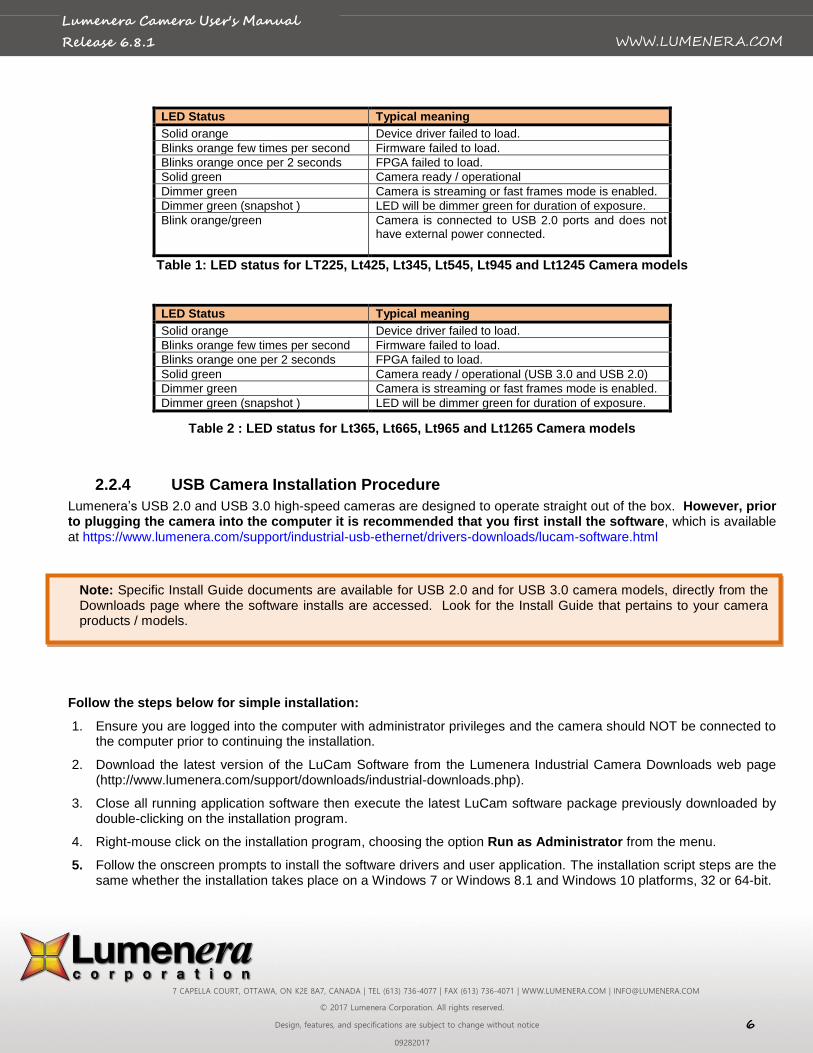
2.2.3 Camera LED indicator
The Lumenera Lu and Lw cameras models include a single function LED that illuminates once the camera device drivers have successfully loaded and the camera is operational. The LED is an amber color for the Lu series and a green color for the Lw series camera models. If the LED fails to illuminate on an Lu or Lw camera model, this typically indicates that the Windows operating system has not successfully loaded the device drivers onto the camera.
For the Lumenera Lt camera models, a multi-function LED that illuminates in either green or orange to provide additional information that can be interpreted by the camera operator. If the indicated status is not easily understood, then contact the Lumenera Support team with a description of the LED behaviour. Check the Table 1 or Table 2 below for the LED appearance and typical meaning.
7 CAPELLA COURT, OTTAWA, ON K2E 8A7, CANADA | TEL (613) 736-4077 | FAX (613) 736-4071 | WWW.LUMENERA.COM | [email protected]
© 2017 Lumenera Corporation. All rights reserved.
Design, features, and specifications are subject to change without notice 6
09282017
WWW.LUMENERA.COM
Lumenera Camera User's Manual
Release 6.8.1
LED Status Typical meaning
Solid orange Device driver failed to load.
Blinks orange few times per second Firmware failed to load.
Blinks orange once per 2 seconds FPGA failed to load.
Solid green Camera ready / operational
Dimmer green Camera is streaming or fast frames mode is enabled.
Dimmer green (snapshot ) LED will be dimmer green for duration of exposure.
Blink orange/green Camera is connected to USB 2.0 ports and does not have external power connected.
Table 1: LED status for LT225, Lt425, Lt345, Lt545, Lt945 and Lt1245 Camera models
LED Status Typical meaning
Solid orange Device driver failed to load.
Blinks orange few times per second Firmware failed to load.
Blinks orange one per 2 seconds FPGA failed to load.
Solid green Camera ready / operational (USB 3.0 and USB 2.0)
Dimmer green Camera is streaming or fast frames mode is enabled.
Dimmer green (snapshot ) LED will be dimmer green for duration of exposure.
Table 2 : LED status for Lt365, Lt665, Lt965 and Lt1265 Camera models
2.2.4 USB Camera Installation Procedure
Lumenera’s USB 2.0 and USB 3.0 high-speed cameras are designed to operate straight out of the box. However, prior to plugging the camera into the computer it is recommended that you first install the software, which is available at https://www.lumenera.com/support/industrial-usb-ethernet/drivers-downloads/lucam-software.html
Follow the steps below for simple installation:
1. Ensure you are logged into the computer with administrator privileges and the camera should NOT be connected to the computer prior to continuing the installation.
2. Download the latest version of the LuCam Software from the Lumenera Industrial Camera Downloads web page (http://www.lumenera.com/support/downloads/industrial-downloads.php).
3. Close all running application software then execute the latest LuCam software package previously downloaded by double-clicking on the installation program.
4. Right-mouse click on the installation program, choosing the option Run as Administrator from the menu.
5. Follow the onscreen prompts to install the software drivers and user application. The installation script steps are the same whether the installation takes place on a Windows 7 or Windows 8.1 and Windows 10 platforms, 32 or 64-bit.
Note: Specific Install Guide documents are available for USB 2.0 and for USB 3.0 camera models, directly from the Downloads page where the software installs are accessed. Look for the Install Guide that pertains to your camera products / models.
7 CAPELLA COURT, OTTAWA, ON K2E 8A7, CANADA | TEL (613) 736-4077 | FAX (613) 736-4071 | WWW.LUMENERA.COM | [email protected]
© 2017 Lumenera Corporation. All rights reserved.
Design, features, and specifications are subject to change without notice 7
09282017
WWW.LUMENERA.COM
Lumenera Camera User's Manual
Release 6.8.1
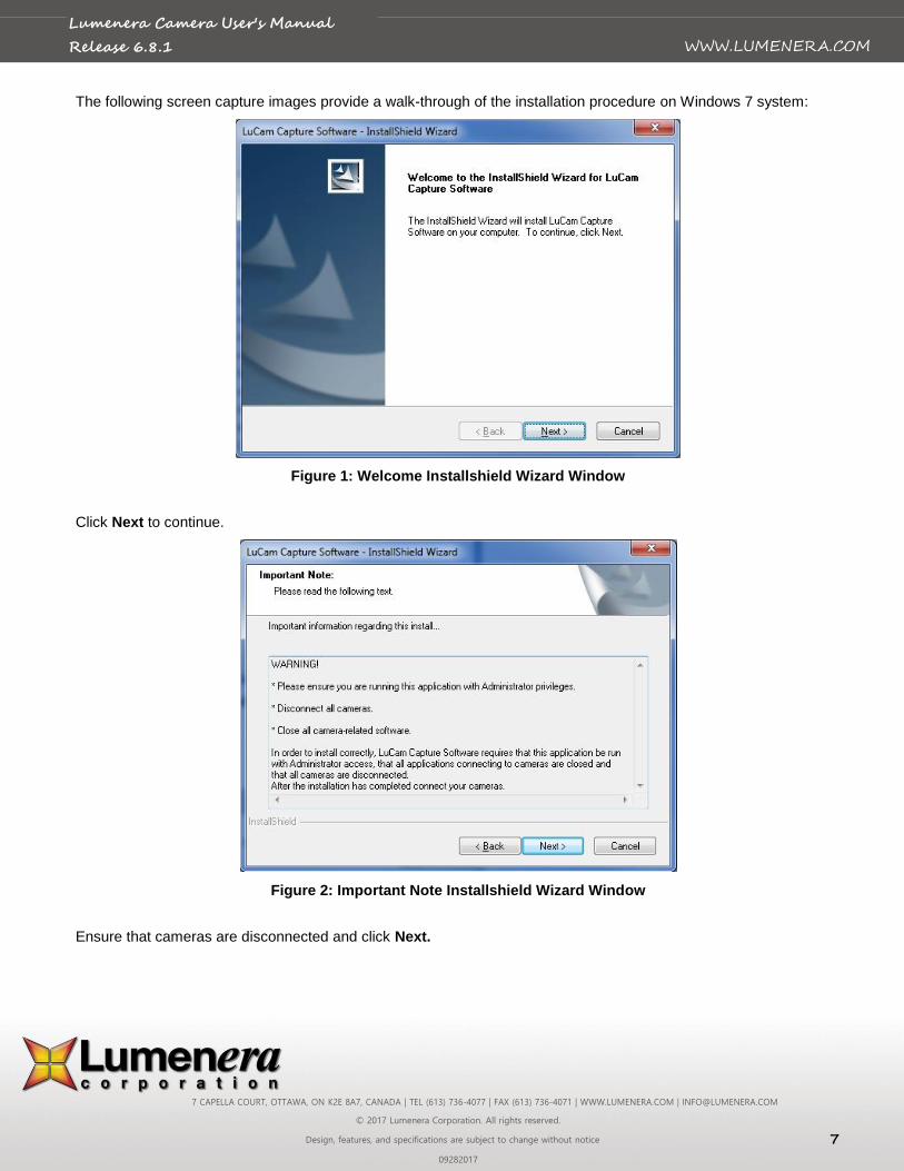
The following screen capture images provide a walk-through of the installation procedure on Windows 7 system:
Figure 1: Welcome Installshield Wizard Window
Click Next to continue.
Figure 2: Important Note Installshield Wizard Window
Ensure that cameras are disconnected and click Next.
7 CAPELLA COURT, OTTAWA, ON K2E 8A7, CANADA | TEL (613) 736-4077 | FAX (613) 736-4071 | WWW.LUMENERA.COM | [email protected]
© 2017 Lumenera Corporation. All rights reserved.
Design, features, and specifications are subject to change without notice 8
09282017
WWW.LUMENERA.COM
Lumenera Camera User's Manual
Release 6.8.1
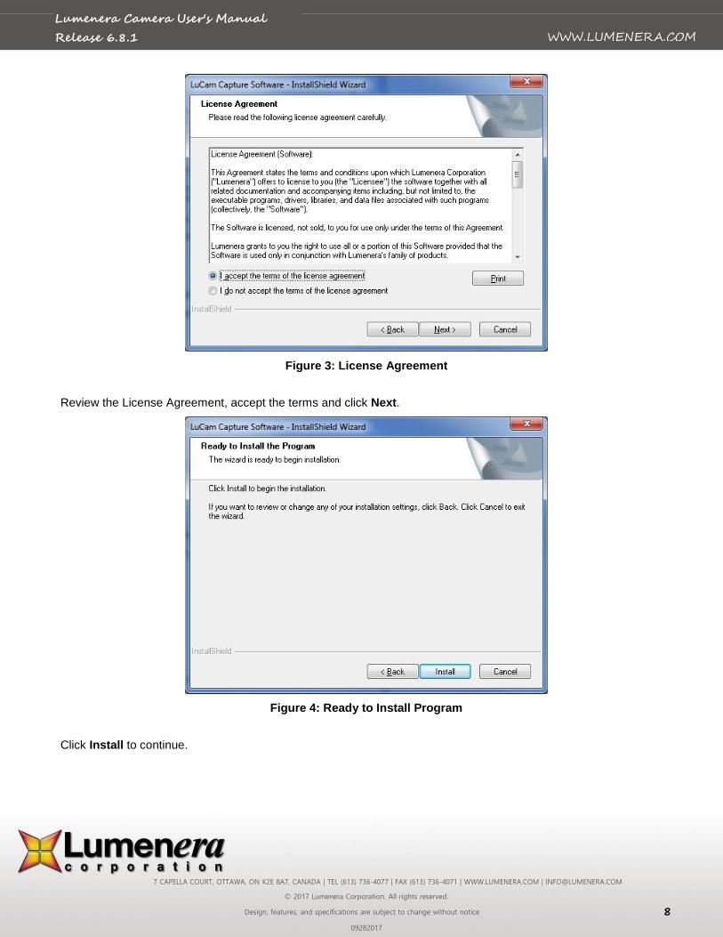
Figure 3: License Agreement
Review the License Agreement, accept the terms and click Next.
Figure 4: Ready to Install Program
Click Install to continue.
7 CAPELLA COURT, OTTAWA, ON K2E 8A7, CANADA | TEL (613) 736-4077 | FAX (613) 736-4071 | WWW.LUMENERA.COM | [email protected]
© 2017 Lumenera Corporation. All rights reserved.
Design, features, and specifications are subject to change without notice 9
09282017
WWW.LUMENERA.COM
Lumenera Camera User's Manual
Release 6.8.1
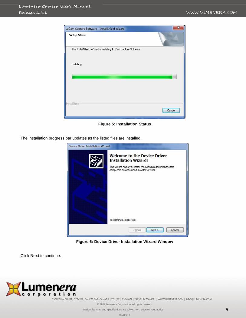
Figure 5: Installation Status
The installation progress bar updates as the listed files are installed.
Figure 6: Device Driver Installation Wizard Window
Click Next to continue.
7 CAPELLA COURT, OTTAWA, ON K2E 8A7, CANADA | TEL (613) 736-4077 | FAX (613) 736-4071 | WWW.LUMENERA.COM | [email protected]
© 2017 Lumenera Corporation. All rights reserved.
Design, features, and specifications are subject to change without notice 10
09282017
WWW.LUMENERA.COM
Lumenera Camera User's Manual
Release 6.8.1
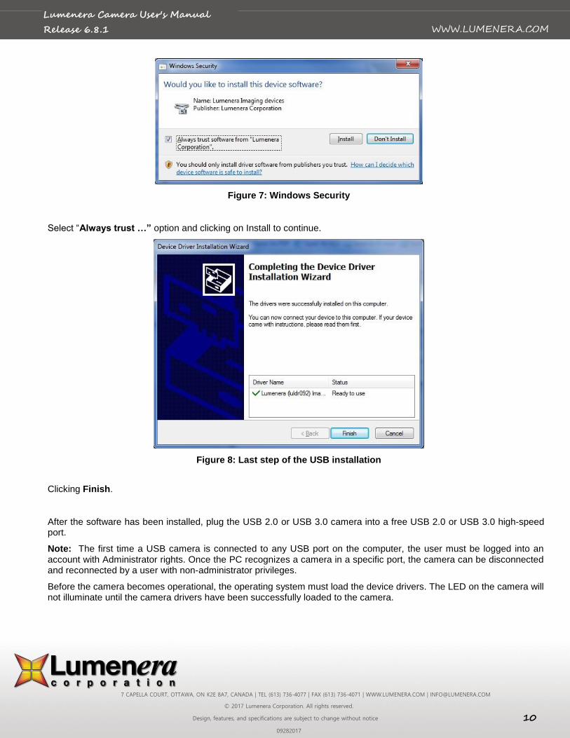
Figure 7: Windows Security
Select “Always trust …” option and clicking on Install to continue.
Figure 8: Last step of the USB installation
Clicking Finish.
After the software has been installed, plug the USB 2.0 or USB 3.0 camera into a free USB 2.0 or USB 3.0 high-speed port.
Note: The first time a USB camera is connected to any USB port on the computer, the user must be logged into an account with Administrator rights. Once the PC recognizes a camera in a specific port, the camera can be disconnected and reconnected by a user with non-administrator privileges.
Before the camera becomes operational, the operating system must load the device drivers. The LED on the camera will not illuminate until the camera drivers have been successfully loaded to the camera.
7 CAPELLA COURT, OTTAWA, ON K2E 8A7, CANADA | TEL (613) 736-4077 | FAX (613) 736-4071 | WWW.LUMENERA.COM | [email protected]
© 2017 Lumenera Corporation. All rights reserved.
Design, features, and specifications are subject to change without notice 11
09282017
WWW.LUMENERA.COM
Lumenera Camera User's Manual
Release 6.8.1
2.2.5 GigE Cameras Installation Procedure
1. Ensure you are logged into the computer with administrator privileges prior to continuing the installation.
2. Download the latest version of the LgCam Software from the Lumenera Industrial Camera Downloads web page (https://www.lumenera.com/support/industrial-usb-ethernet/drivers-downloads/lucam-software.html).
3. Close all running application software then execute the latest LgCam software package previously downloaded by double-clicking on the installation program. The camera should NOT be connected to the computer at this point.
4. Follow the onscreen prompts to install the software drivers and user application. The installation script steps are the same whether the installation takes place on a Windows 7, Windows 8.1 or Windows 10 platforms, 32 or 64-bit.
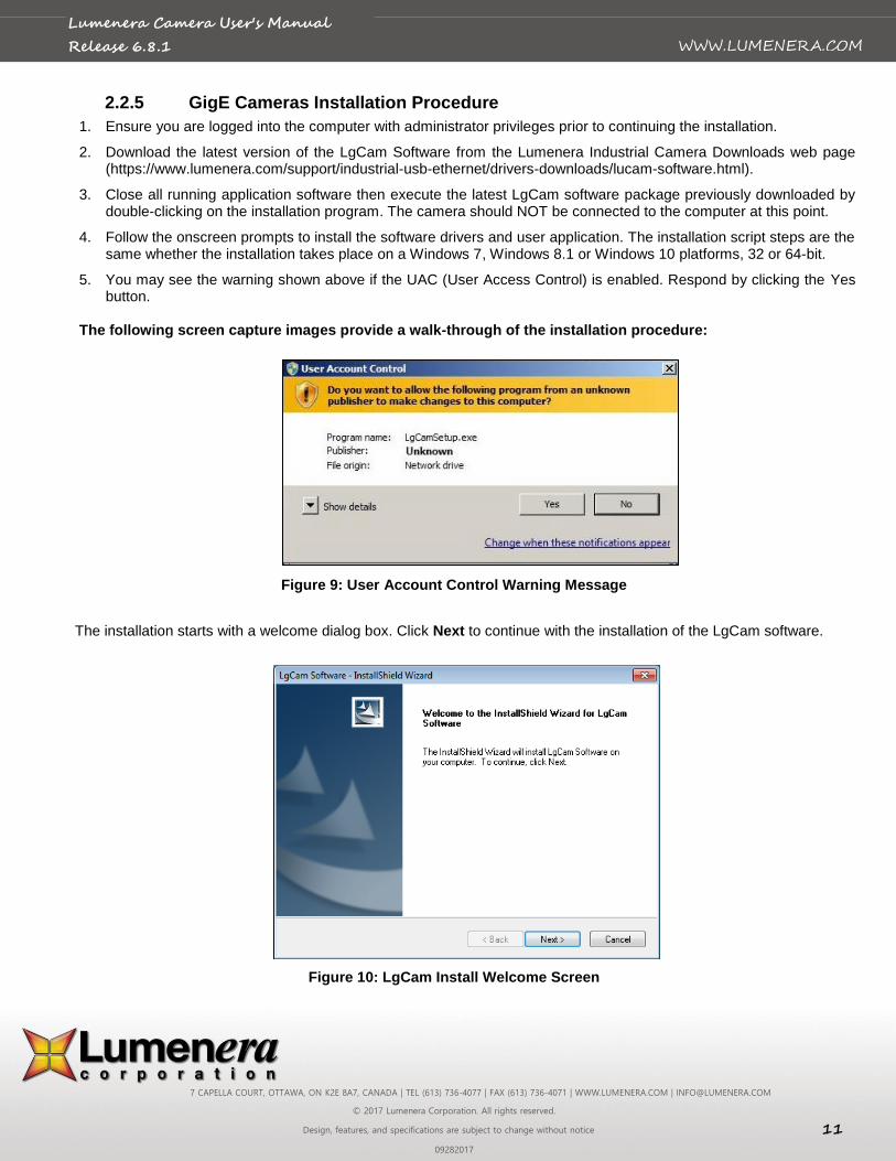
5. You may see the warning shown above if the UAC (User Access Control) is enabled. Respond by clicking the Yes button.
The following screen capture images provide a walk-through of the installation procedure:
Figure 9: User Account Control Warning Message
The installation starts with a welcome dialog box. Click Next to continue with the installation of the LgCam software.
Figure 10: LgCam Install Welcome Screen
7 CAPELLA COURT, OTTAWA, ON K2E 8A7, CANADA | TEL (613) 736-4077 | FAX (613) 736-4071 | WWW.LUMENERA.COM | [email protected]
© 2017 Lumenera Corporation. All rights reserved.
Design, features, and specifications are subject to change without notice 12
09282017
WWW.LUMENERA.COM
Lumenera Camera User's Manual
Release 6.8.1
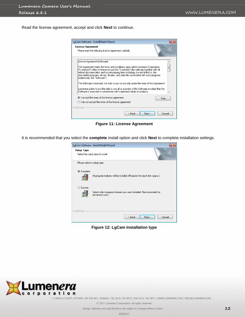
Read the license agreement, accept and click Next to continue.
Figure 11: License Agreement
It is recommended that you select the complete install option and click Next to complete installation settings.
Figure 12: LgCam Installation type
7 CAPELLA COURT, OTTAWA, ON K2E 8A7, CANADA | TEL (613) 736-4077 | FAX (613) 736-4071 | WWW.LUMENERA.COM | [email protected]
© 2017 Lumenera Corporation. All rights reserved.
Design, features, and specifications are subject to change without notice 13
09282017
WWW.LUMENERA.COM
Lumenera Camera User's Manual
Release 6.8.1
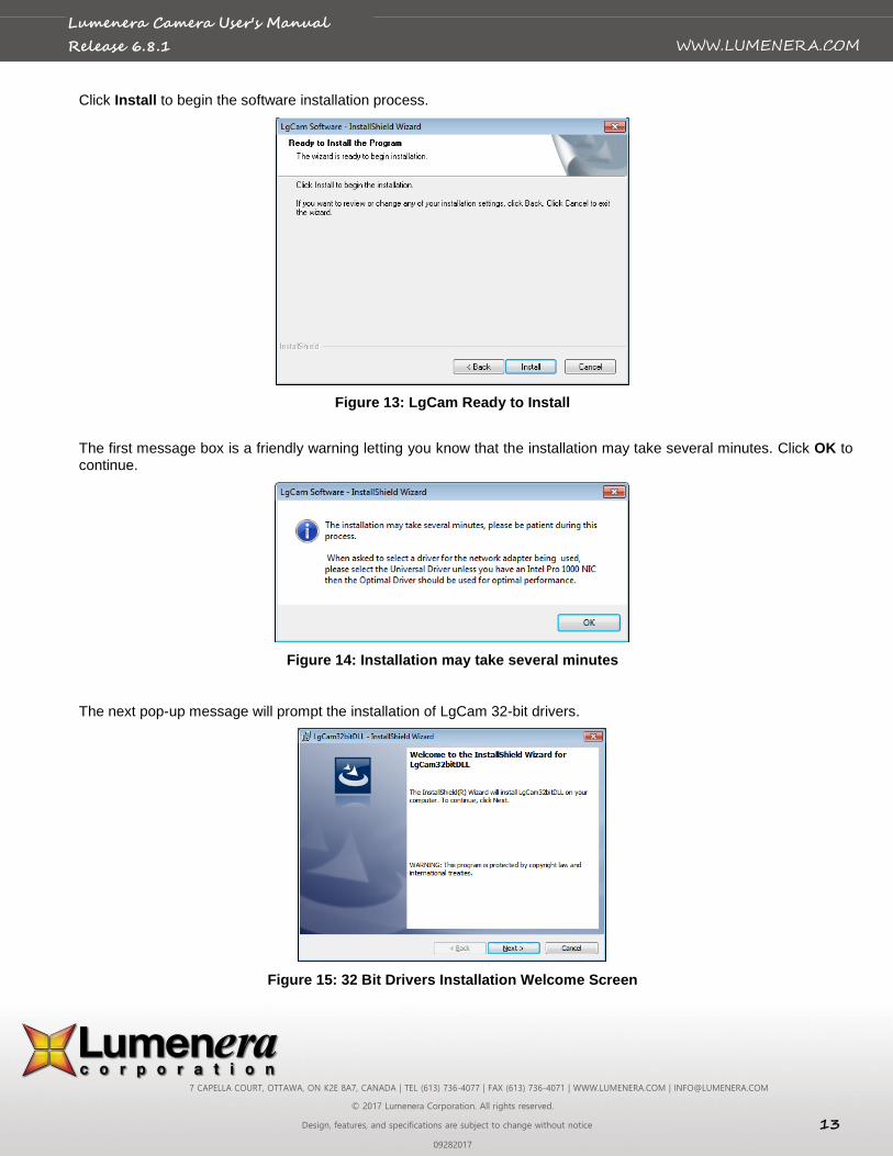
Click Install to begin the software installation process.
Figure 13: LgCam Ready to Install
The first message box is a friendly warning letting you know that the installation may take several minutes. Click OK to continue.
Figure 14: Installation may take several minutes
The next pop-up message will prompt the installation of LgCam 32-bit drivers.
Figure 15: 32 Bit Drivers Installation Welcome Screen
7 CAPELLA COURT, OTTAWA, ON K2E 8A7, CANADA | TEL (613) 736-4077 | FAX (613) 736-4071 | WWW.LUMENERA.COM | [email protected]
© 2017 Lumenera Corporation. All rights reserved.
Design, features, and specifications are subject to change without notice 14
09282017
WWW.LUMENERA.COM
Lumenera Camera User's Manual
Release 6.8.1
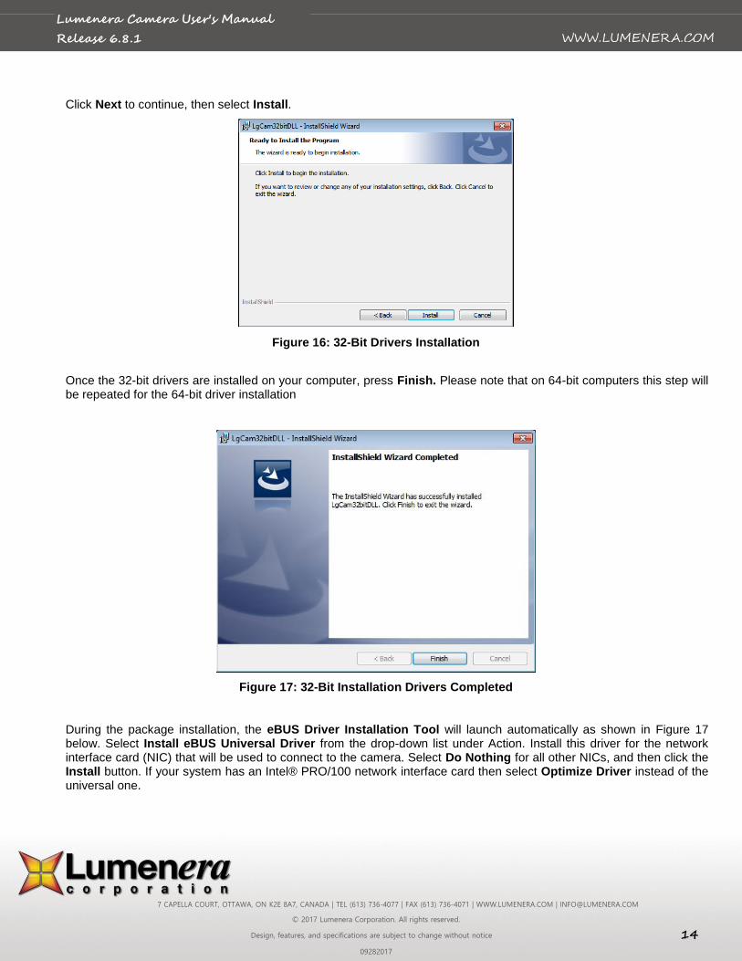
Click Next to continue, then select Install.
Figure 16: 32-Bit Drivers Installation
Once the 32-bit drivers are installed on your computer, press Finish. Please note that on 64-bit computers this step will be repeated for the 64-bit driver installation
Figure 17: 32-Bit Installation Drivers Completed
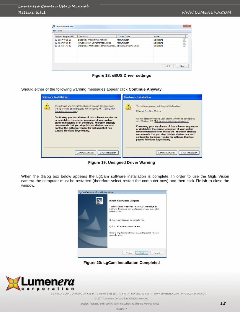
During the package installation, the eBUS Driver Installation Tool will launch automatically as shown in Figure 17 below. Select Install eBUS Universal Driver from the drop-down list under Action. Install this driver for the network interface card (NIC) that will be used to connect to the camera. Select Do Nothing for all other NICs, and then click the Install button. If your system has an Intel® PRO/100 network interface card then select Optimize Driver instead of the universal one.
7 CAPELLA COURT, OTTAWA, ON K2E 8A7, CANADA | TEL (613) 736-4077 | FAX (613) 736-4071 | WWW.LUMENERA.COM | [email protected]
© 2017 Lumenera Corporation. All rights reserved.
Design, features, and specifications are subject to change without notice 15
09282017
WWW.LUMENERA.COM
Lumenera Camera User's Manual
Release 6.8.1
Figure 18: eBUS Driver settings
Should either of the following warning messages appear click Continue Anyway.
Figure 19: Unsigned Driver Warning
When the dialog box below appears the LgCam software installation is complete. In order to use the GigE Vision camera the computer must be restarted (therefore select restart the computer now) and then click Finish to close the window.
Figure 20: LgCam Installation Completed
7 CAPELLA COURT, OTTAWA, ON K2E 8A7, CANADA | TEL (613) 736-4077 | FAX (613) 736-4071 | WWW.LUMENERA.COM | [email protected]
© 2017 Lumenera Corporation. All rights reserved.
Design, features, and specifications are subject to change without notice 16
09282017
WWW.LUMENERA.COM
Lumenera Camera User's Manual
Release 6.8.1
2.2.6 USB Plug-and-Play Device Recognition
Windows 7, Windows 8 & Windows 10Systems:
The Lumenera USB camera drivers are digitally signed with Microsoft. Under Windows 7 operating systems the camera will be automatically identified, and the drivers will be silently loaded in the background. Typically a small balloon dialog appears in the lower right hand side of the screen indicating that a device has been detected and the drivers are loading. Allow up to 1 minute for the device drivers to load, and when the LED is illuminated on the camera it is operational.
Run the LuCam Capture application software from your Start menu to control the camera.
2.2.7 Software Upgrade Procedure
The Software Upgrade procedure is similar to the original software installation. If you have installed a previous version of the software you should uninstall it prior to running the Software Upgrade.
Note: Should the Uninstall Script identify that a reboot is required, please ensure that you perform this step by rebooting your computer before installing the Software Upgrade. Failure to do so could cause difficulties with any future installations.
If you run the Software Upgrade without uninstalling the older version, it will uninstall it for you. The Software Upgrade procedure will launch automatically to install the new software, immediately following the un-install.
USB 3.0 and GigE camera model may require a product firmware upgrade. The software to upgrade product firmware could be downloaded at http://www.lumenera.com/support/downloads/industrial-downloads.php. The installation instruction will be included in the package and it is highly suggested that you review these instructions prior to proceed to a product update.
2.2.8 USB Camera Troubleshooting
In the event that the Lumenera USB camera is not functional, the most likely reason is that the drivers were not loaded to the camera. This can occur when a camera was connected to the PC prior to the software being installed. When the USB plug-and-play device detection is initiated for any new device, the operating system will effectively quarantine the device if it cannot locate the appropriate driver files. In this event, the camera drivers will be blocked from loading even after the drivers are installed, unless the device detection process is invoked manually. The steps to correct this only take a couple of minutes to complete.
Make sure that the Lucam software is installed before proceeding.
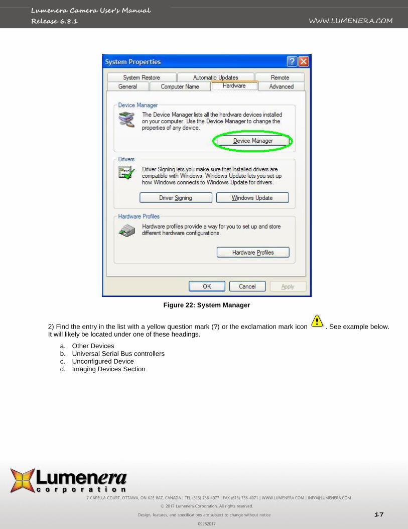
1) Right mouse click the “My Computer” icon on your computer screen and choose “Properties”. Click “Device Manager” on System Properties window.
A keyboard shortcut exists to access this menu quickly, press the “Windows / Start” key and the “Pause / Break” keys simultaneously:
Figure 21: Shortcut System Manager
7 CAPELLA COURT, OTTAWA, ON K2E 8A7, CANADA | TEL (613) 736-4077 | FAX (613) 736-4071 | WWW.LUMENERA.COM | [email protected]
© 2017 Lumenera Corporation. All rights reserved.
Design, features, and specifications are subject to change without notice 17
09282017
WWW.LUMENERA.COM
Lumenera Camera User's Manual
Release 6.8.1
Figure 22: System Manager
2) Find the entry in the list with a yellow question mark (?) or the exclamation mark icon . See example below. It will likely be located under one of these headings.
a. Other Devices b. Universal Serial Bus controllers c. Unconfigured Device d. Imaging Devices Section
7 CAPELLA COURT, OTTAWA, ON K2E 8A7, CANADA | TEL (613) 736-4077 | FAX (613) 736-4071 | WWW.LUMENERA.COM | [email protected]
© 2017 Lumenera Corporation. All rights reserved.
Design, features, and specifications are subject to change without notice 18
09282017
WWW.LUMENERA.COM
Lumenera Camera User's Manual
Release 6.8.1
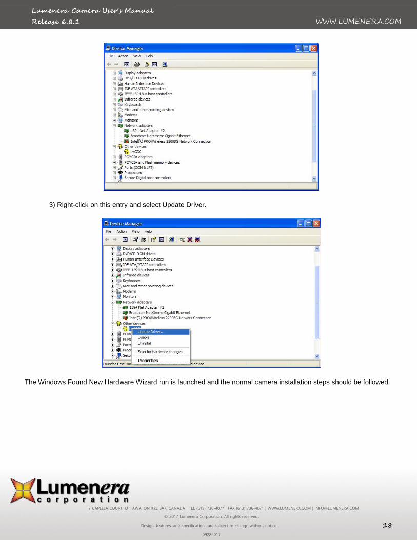
3) Right-click on this entry and select Update Driver.
The Windows Found New Hardware Wizard run is launched and the normal camera installation steps should be followed.
7 CAPELLA COURT, OTTAWA, ON K2E 8A7, CANADA | TEL (613) 736-4077 | FAX (613) 736-4071 | WWW.LUMENERA.COM | [email protected]
© 2017 Lumenera Corporation. All rights reserved.
Design, features, and specifications are subject to change without notice 19
09282017
WWW.LUMENERA.COM
Lumenera Camera User's Manual
Release 6.8.1
2.3 Technical Assistance
If you need assistance with the installation, use of the software or if you require help with general camera operation please contact the Technical Assistance Centre (TAC) via email at:
or by phone at +1-613-736-4077 (press 2 from the auto attendant)
To obtain the latest software release and other technical information visit the technical support tab on the Lumenera website at:
www.lumenera.com
Our support website contains technical information available to the general public such as Frequently Asked Questions (FAQ’s). For our Lumenera customers we provide a Knowledge Base with more product-specific solutions and a Download Centre for customers to obtain the most recent software releases.
As a customer you will need to provide the TAC with some basic information to gain access to the customer Knowledge Base and the Download Centre. Please provide the following details via email to [email protected] to obtain a user name and password:
Name, company name, address and telephone number
Camera model and serial number
Purchase information (e.g. did you purchase from an OEM or distributor?)
SDK password that was provided to you if SDK was purchase or the proof of its purchase.
Upon providing the above information, you will receive your access information via email from the TAC team.
2.4 Using the Installed Software
All of the necessary software and device drivers are contained in an installation program available on the Lumenera website under the Support section.
The following files are installed when you run the installation program:
2.4.1 Drivers & INF
The Lumenera camera driver files come as a pair for each camera model, supporting a two-stage driver load process. These two files have the .sys extension and are copied to …\SYSTEM32\DRIVERS folder in the standard Windows folder on your system. These files are named LucamXXX.sys and LuldrXXX.sys or LwcamXXX.sys and LwldrXXX.sys, ltcamusb.sys or LccamXXX and Lcldr (the XXX represents the 3 digit camera ID number).
Each of the .sys files is called into operation by a custom file with the .inf extension The location of the inf files is controlled by the Windows O/S. They are installed and copied to the …\INF folder in the standard Windows folder on your system. There are up to two of these files for each camera model supported by the software. The names of these files are LucamXXX.inf and LuldrXXX.inf or LwcamXXX.inf and LwldrXXX.inf (the XXX represents the 3 digit camera ID number). USB 3.0 cameras are all using the same driver ltcamusb.inf.
Lumenera uses a custom utility to ensure that the driver files are installed and registered to conform to Windows logo testing. The application is called luihlp.exe and is included with the driver-only installation packages described below.
2.4.2 DirectShow Filters
Several DirectShow (or WDM) related files are installed in the …\SYSTEM folder in the standard Windows folder on your system. All of these files have the .ax extension. These files are stored in the program files folder where the Lumenera software is installed under:
7 CAPELLA COURT, OTTAWA, ON K2E 8A7, CANADA | TEL (613) 736-4077 | FAX (613) 736-4071 | WWW.LUMENERA.COM | [email protected]
© 2017 Lumenera Corporation. All rights reserved.
Design, features, and specifications are subject to change without notice 20
09282017
WWW.LUMENERA.COM
Lumenera Camera User's Manual
Release 6.8.1
Uninstall_LuCam_Software
When these DirectShow filter files are installed, they are registered with the O/S as residing in a specific folder location. If these files are deleted or moved to a different folder location without being correctly re-registered, then the camera preview and captured images will not display correctly. Their names are:
- Lutf.ax
- Lucustom.ax
- Lustrcfg.ax
- Lgsrcflt.ax (in case of GigE Vision camera)
2.4.3 Application Software
2.4.3.1 USB products
The LuCam Capture application (LuCam.exe) is installed in the default location for 32 bit or 64 bit Windows:
C:\Program Files\Lumenera Corporation\LuCam Capture Software\ (32 bit Windows)
C:\Program Files (x86)\Lumenera Corporation\LuCam Capture Software\ (64 bit Windows)
A shortcut to this application is added to the Start Menu at the default location :
Start→All Programs→Lumenera→LuCam Capture→LuCam Capture.exe
2.4.3.2 GigE Vision products
The LgCam Capture application (LgCam.exe) is installed in the directory selected during the installation process. The default location is:
C:\Program Files\Lumenera Corporation\LgCam
A shortcut to this application is added to the Start Menu at the location selected during installation. The default location is:
Start→All Programs→Lumenera→LgCam→LgCam.exe
2.4.4 Sample Application Executables
Every installation of LuCam software and LgCam software includes a set of executable sample programs to facilitate the evaluation of the camera functionality and performance. By default these applications are installed to C:\Program File\Lumenera Corporation\LuCam Capture Software\Executables directory for 32 bit Windows systems. For 64 bit Windows systems, the executables will be installed in the C:\Program Files (x86)\Lumenera Corporation\LuCam Capture Software\Executables directory. The majority of the LuCam API functions are exercised in these sample executables. Support for these sample programs is not provided. Although they are periodically maintained some of the samples do not function with every Lumenera camera model.
2.4.5 Software Development Kit (SDK)
The software development kit is required for software development with Lumenera camera models. In order to minimize customer development cycle, Lumenera is providing one SDK that is shared by our USB2.0, USB3.0, GigE and INFINITY products. Documentation, Microsoft Visual Studio 2010 projects (C++, C# .NET and VB .NET), Software support and plug-in development support (MATLAB Windows, LabVIEW Windows) are included. This package can be directly downloaded for free from our website
https://www.lumenera.com/support/industrial-usb-ethernet/drivers-downloads/lucam-software.html.
7 CAPELLA COURT, OTTAWA, ON K2E 8A7, CANADA | TEL (613) 736-4077 | FAX (613) 736-4071 | WWW.LUMENERA.COM | [email protected]
© 2017 Lumenera Corporation. All rights reserved.
Design, features, and specifications are subject to change without notice 21
09282017
WWW.LUMENERA.COM
Lumenera Camera User's Manual
Release 6.8.1
2.4.6 Documentation
Documentation consisting of this User’s Manual, the API reference manual and Quick Start Guide, is installed in a folder called “Documentation” in the directory selected during the installation process. The default location is:
C:\Program Files\Lumenera Corporation\LuCam Capture Software (32 bit Windows)
C:\Program Files(x86)\Lumenera Corporation\LuCam Capture Software (64 bit Windows)
C:\Program Files\Lumenera Corporation\LgCam Software (32bit Windows)
C:\Program Files(x86)\Lumenera Corporation\LgCam Software (64bit Windows)
The latest documentation release is included with the download of the current release of LuCam Software and LgCam Software, available on the Support tab of the Lumenera website at:
www.lumenera.com
2.4.7 Driver Only Installation Packages
Included with the SDK are Driver Only installation packages that can be used to install and run the specific camera models on any computer without the need to install the complete software package. In each camera model directory you will find the camera driver and .inf files, the DirectShow files and the API DLL files. Also included in the directory, there is an installation batch file that can be used to install these files or used as a reference for your own installation script and the Microsoft regsvr32.exe application needed to register the Lutf.ax DirectShow filter file. These packages are installed in a folder called “Driver Only Installations” in the directory selected during the installation process. The default location is:
C:\Program Files\Lumenera Corporation\Lumenera Camera SDK\Redist (32 bit Windows)
C:\Program Files(x86)\Lumenera Corporation\ Lumenera Camera SDK\Redist (64 bit Windows)
The files contained in these directories are the same ones used by the camera. If, during your development, a camera file update is required, use the updated files as part of your installation package. You can replace the files in this directory as necessary.
Note: LgCam Software installation does not have a driver only installation package, therefore the complete installation process is required to ensure all dependencies are installed.
7 CAPELLA COURT, OTTAWA, ON K2E 8A7, CANADA | TEL (613) 736-4077 | FAX (613) 736-4071 | WWW.LUMENERA.COM | [email protected]
© 2017 Lumenera Corporation. All rights reserved.
Design, features, and specifications are subject to change without notice 22
09282017
WWW.LUMENERA.COM
Lumenera Camera User's Manual
Release 6.8.1
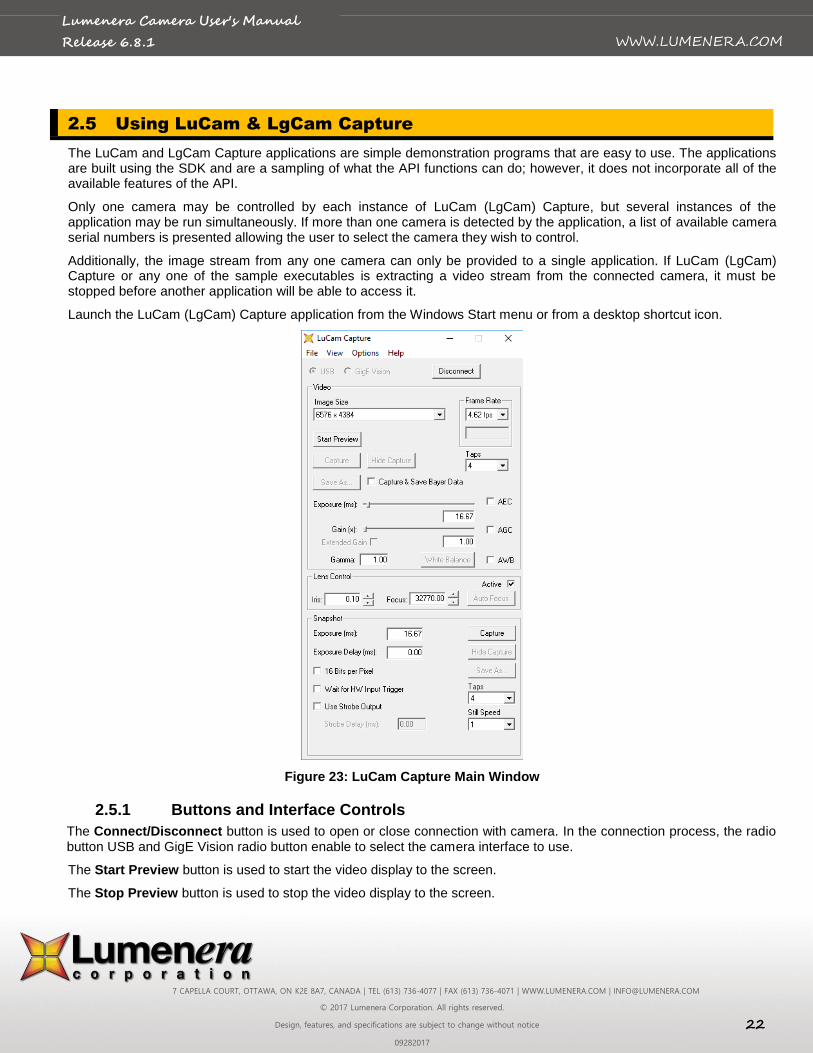
2.5 Using LuCam & LgCam Capture
The LuCam and LgCam Capture applications are simple demonstration programs that are easy to use. The applications are built using the SDK and are a sampling of what the API functions can do; however, it does not incorporate all of the available features of the API.
Only one camera may be controlled by each instance of LuCam (LgCam) Capture, but several instances of the application may be run simultaneously. If more than one camera is detected by the application, a list of available camera serial numbers is presented allowing the user to select the camera they wish to control.
Additionally, the image stream from any one camera can only be provided to a single application. If LuCam (LgCam) Capture or any one of the sample executables is extracting a video stream from the connected camera, it must be stopped before another application will be able to access it.
Launch the LuCam (LgCam) Capture application from the Windows Start menu or from a desktop shortcut icon.
Figure 23: LuCam Capture Main Window
2.5.1 Buttons and Interface Controls
The Connect/Disconnect button is used to open or close connection with camera. In the connection process, the radio button USB and GigE Vision radio button enable to select the camera interface to use.
The Start Preview button is used to start the video display to the screen.
The Stop Preview button is used to stop the video display to the screen.

7 CAPELLA COURT, OTTAWA, ON K2E 8A7, CANADA | TEL (613) 736-4077 | FAX (613) 736-4071 | WWW.LUMENERA.COM | [email protected]
© 2017 Lumenera Corporation. All rights reserved.
Design, features, and specifications are subject to change without notice 23
09282017
WWW.LUMENERA.COM
Lumenera Camera User's Manual
Release 6.8.1
The video frame Capture button is used to grab a frame of video from the video stream and display it on screen.
The Save As button is used to save the image to disk in one of the available formats.
The Hide Capture button will close the image display window.
The Capture & Save Bayer Data toggle button allows you to view and save the raw Bayer data that comes from the camera, before it is processed into 24-bit RGB data (color cameras only). If a captured image is currently being displayed, this button will toggle the image between raw Bayer and processed 24-bit data.
2.5.2 Dialog Items
Video Image Control
The Image Size dropdown list provides the available video display resolutions. The Preview must be stopped in order to switch between the various image sizes.
The Frame Rate dropdown box provides a list of available display frame rates. Not all cameras have this capability.
The Taps dropdown box provides a list of number of taps available to select. Not all cameras support multiple taps.
The Exposure text box or slider is used to adjust the video exposure time in milliseconds.
The AEC toggle button is used to toggle the Automatic Exposure Control (not available for all cameras). When selected, the slider changes to Luminance Target allowing you to select the average brightness you want to maintain as ambient lighting changes. The exposure will be automatically adjusted in an attempt to maintain the average brightness.
The Gain text box or slider is used to adjust the global gain of the camera for both video mode and when using the Snapshot mode (described below). The gain value is a multiplicative factor, so a value of 1 means no gain. The value of every pixel in the image is multiplied by the gain value, resulting in an increase in image brightness. When the gain setting is increased, any sensor noise will be amplified, along with the image data, and the picture quality will be degraded. The higher the gain, the more noticeable this is.
The AGC toggle button is used to toggle the Automatic Gain Control (not available for all cameras). When selected, the slider changes to Luminance Target allowing you to select the average scene brightness that you want to maintain as ambient lighting changes. The gain will be automatically adjusted in an attempt to maintain the average brightness.
Note: When both AEC and AGC are selected, if an increase in brightness is required, exposure is amplified first until its limit is reached and then gain is adjusted. When a decrease in brightness is required, gain is reduced first until its limit is reached and then exposure is adjusted. This maintains the best image quality.
The Gamma value is applied to the image to make it look better on screen. It is used to correct the non-linearity inherent in most CRT monitors. A value of 1 represents no gamma correction. Values less than one will make the image appear darker while a value greater than one will make the image appear brighter. For more information about Gamma and why it is used consult: www.poynton.com/GammaFAQ.html.
The WB button adjusts a camera’s video preview color gain settings (white balance), based on the overall image, using the Gray World Algorithm. It is done in software by grabbing a video frame, analyzing it, adjusting the color gains and repeating, until the colors in the image are balanced (resulting in an equal amount of Red, Blue and Green in the image). It is best to put a neutral target (e.g. white or grey paper) in front of the camera before performing a color balance. For best results, the image exposure time should be adjusted so that the scene does not contain any saturated pixels (values at maximum brightness).
The AWB toggle button is used to enable or disable continuous white balance. If enabled, the camera will automatically adjust white balance on each video frames received.
2.5.3 View Menu Items
Preview Frame Rate will display the average frame rate of the preview window. The average is computed over the whole time span that the display has been actively previewing since the last time Start Preview was pressed.
7 CAPELLA COURT, OTTAWA, ON K2E 8A7, CANADA | TEL (613) 736-4077 | FAX (613) 736-4071 | WWW.LUMENERA.COM | [email protected]
© 2017 Lumenera Corporation. All rights reserved.
Design, features, and specifications are subject to change without notice 24
09282017
WWW.LUMENERA.COM
Lumenera Camera User's Manual
Release 6.8.1
Show Image Stats displays a window showing the average image intensity for both the preview and snapshots. It takes into consideration the current pixel depth. It also shows the average color pixel value in each mode. When the “Update for …” options are selected, the average values are updated with each new image received. Deselecting these options disables the updates.
Move Capture Window to Origin will move the capture window to the top left corner of your desktop.
2.5.4 Options Menu Items
Read/Write Registers pop up a dialog allowing you to read and write the registers of the camera. This is an advanced function and should not be used without the advice of Lumenera’s technical support staff.
Light Source provides the option of selecting the ambient lighting source that is being used so that the proper colour correction can be performed by the camera. The visual impact resulting from the light source adjustment varies by camera model, and in some cameras the impact is negligible.
Enable Preview 16-bit Mode will place the camera into 16-bit video preview mode. The video preview window will only display the upper 8-bits but when you hit the Capture button will capture 16-bit video frames. (The number of actual valid data bits per pixel will vary by camera model. Refer to the camera datasheet for the output options available for a specific model).
Monochrome Preview puts the camera into monochrome mode.
Sharpen Captured Image applies a sharpening algorithm to the image when it’s captured (not in the live preview). If an image is currently being displayed, this option will toggle the displayed image between sharpened and unsharpened.
Enable Dual Tap Correction is applicable only for the full frame format camera models where the sensor output can be processed through either a single tap or by using a dual tap mode to improve the data throughput.
Image Averaging averages 5 frames of video together to reduce random image noise when the Capture button is pressed. This option will produce undesirable results when the field of view contains objects in motion.
Image Summing sums 5 frames of video together to produce a brighter image when the Capture button is pressed. This option will produce undesirable results when the field of view contains objects in motion. The resulting image will be 5 times brighter than the current preview images.
Hue/Saturation pops up a dialog that allows you to adjust the hue and saturation of the live preview.
Display Video Properties presents a “canned” dialog generated by the LuCam API that allows you to adjust video properties (Exposure, Gain, Gamma, Brightness, and Contrast).
2.5.5 Lens Control section
The Iris spins box control the lens aperture opening. The higher the number is, the bigger the opening is.
The Focus spins box control the focal length in terms of motor steps.
The Auto Focus button will initiate camera to find best focus position to get best image scene sharpness possible.
The Active toggle button will enable of disable the lens control section.
2.5.6 Snapshot Settings
The Exposure value controls the time between the start of image capture and the data read-out for a snapshot, expressed in milliseconds. It is required to hit Enter key when changing the snapshot exposure value.
The Exposure Delay value indicates the time in milliseconds between the receiving the snapshot trigger input and the start of integration on the sensor.
The Capture button is used to grab an image from the camera using its snapshot mode and half-global or global shutter (if available), and display it on screen (See Shutter Types and Camera Modes sections below for more information about snapshot mode and global shutter).

7 CAPELLA COURT, OTTAWA, ON K2E 8A7, CANADA | TEL (613) 736-4077 | FAX (613) 736-4071 | WWW.LUMENERA.COM | [email protected]
© 2017 Lumenera Corporation. All rights reserved.
Design, features, and specifications are subject to change without notice 25
09282017
WWW.LUMENERA.COM
Lumenera Camera User's Manual
Release 6.8.1
The Hide Capture button will close the snapshot image display window.
The Wait for HW Input Trigger toggle is used to specify that the snapshot should be hardware (HW) triggered using the HW trigger input of the camera’s external header. With this option selected, when the Snapshot button is pressed, the software will pause as the camera waits for the HW trigger before returning the image. There is a built-in time-out of 25 seconds after which time if the HW trigger has not occurred, the software will resume operation.
The Use Strobe Trigger toggle is used to specify that during the snapshot exposure, the strobe trigger output should be fired.
The Strobe Delay value indicates the time in milliseconds between the rising edge of strobe output and the rising edge of the strobe trigger pulse.
The Save As button is used to save the snapshot image to disk in one of the available formats.
The 16-Bits per Pixel toggles the camera between 8 and 16-bit data mode for snapshot capture.
The White Balance Gains for Strobe Snapshot values allow you to set the Red, Green and Blue gains to be used during the snapshot capture. This allows you to white balance according to the strobe lighting that is being used. They are only applied if the Use Strobe Trigger option is selected.

7 CAPELLA COURT, OTTAWA, ON K2E 8A7, CANADA | TEL (613) 736-4077 | FAX (613) 736-4071 | WWW.LUMENERA.COM | [email protected]
© 2017 Lumenera Corporation. All rights reserved.
Design, features, and specifications are subject to change without notice 26
09282017
WWW.LUMENERA.COM
Lumenera Camera User's Manual
Release 6.8.1
3 Understanding Your Camera
3.1 Shutter Types and Scanning Mode
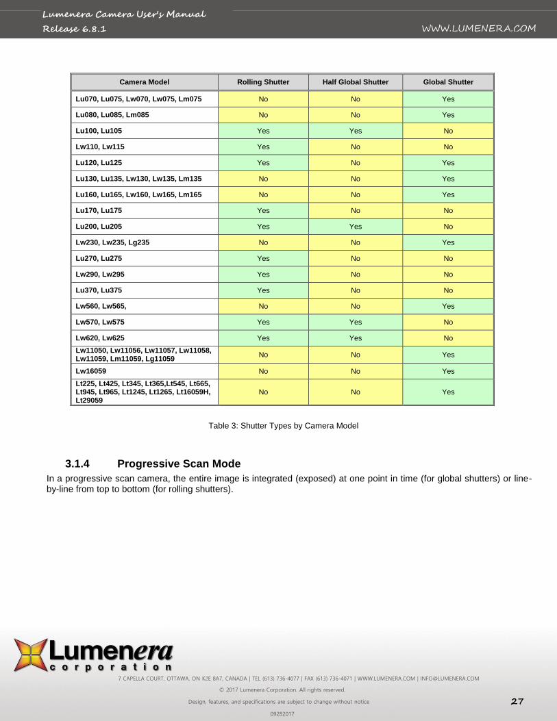
Depending on the camera model that you have, the following electronic shutter types may or may not be present. Check Table 3, at the end of this section, to determine the shutter type associated with each camera model. These types are selectable for the snapshot mode of the camera (described in a later section).
3.1.1 Rolling Shutter
With a rolling shutter the exposure process begins, whereby rows of pixels in the image sensor start exposing in sequence, starting at the top of the image and proceeding row by row down to the bottom. At some later point in time, the readout process begins, whereby rows of pixels are read out in sequence, starting at the top of the image and proceeding row by row down to the bottom in exactly the same manner and at the same speed as the exposure process.
The time delay between a row starting to expose and a row being read out is the integration time, also known as the exposure time. This integration time can be varied from a single line (start exposure followed by a read out while the next line is exposing) up to a full frame time (last line starts exposing at the bottom of the image before reading starts at the top). In some cases, longer exposures can be obtained by delaying the read out even longer (during which time, the entire array is exposing).
Since the integration process moves through the image over some length of time, skewing of moving objects may become apparent. For example, if a vehicle is moving through the image during capture, light from the top of the vehicle will be integrated at some earlier time than light from the bottom of the vehicle, causing the bottom of the vehicle to appear slanted forward in the direction of motion. For most slow moving objects or still image capture, this motion artefact is not noticeable.
3.1.2 Half Global Shutter
With a half global shutter, the entire image array starts exposing at the same time (globally). At some later point in time, the readout process begins, whereby rows of pixels are read out in sequence, starting at the top of the image and proceeding row by row down to the bottom (exactly like the rolling shutter case).
The time between the global start of integration and the start of readout is defined as the exposure time. However, since during readout of the image the lines are still integrating (like rolling shutter), the actual image exposure differs from the top to the bottom. The difference is the time taken to readout the image and varies for each camera (70 ms is typical). Under bright ambient lighting conditions, the image will appear brighter; the further down the image you go. A half-global shutter is most effective when used under controlled lighting (e.g. strobe flash).
Because integration continues to occur during readout, the skewing motion artefact can still occur.
3.1.3 Global Shutter
With a global shutter, the entire image array starts exposing at the same time (globally). At some later point in time, the entire image array stops exposing at the same time and the image is read out in sequence, starting at the top of the image and proceeding row by row down to the bottom (sometimes odd rows are read out first followed by the even rows). The difference from the other modes is that during readout, the imager is no longer integrating light.
The time delay between the start of exposure and end of exposure is defined as the exposure time and it represents the total amount of time that the image integrates.
Because all the pixels start exposure at the same time, integrate over the same interval, and stop exposing at the same time, there is no potential for motion artefacts as there is in the other modes.
7 CAPELLA COURT, OTTAWA, ON K2E 8A7, CANADA | TEL (613) 736-4077 | FAX (613) 736-4071 | WWW.LUMENERA.COM | [email protected]
© 2017 Lumenera Corporation. All rights reserved.
Design, features, and specifications are subject to change without notice 27
09282017
WWW.LUMENERA.COM
Lumenera Camera User's Manual
Release 6.8.1
Camera Model Rolling Shutter Half Global Shutter Global Shutter
Lu070, Lu075, Lw070, Lw075, Lm075 No No Yes
Lu080, Lu085, Lm085 No No Yes
Lu100, Lu105 Yes Yes No
Lw110, Lw115 Yes No No
Lu120, Lu125 Yes No Yes
Lu130, Lu135, Lw130, Lw135, Lm135 No No Yes
Lu160, Lu165, Lw160, Lw165, Lm165 No No Yes
Lu170, Lu175 Yes No No
Lu200, Lu205 Yes Yes No
Lw230, Lw235, Lg235 No No Yes
Lu270, Lu275 Yes No No
Lw290, Lw295 Yes No No
Lu370, Lu375 Yes No No
Lw560, Lw565, No No Yes
Lw570, Lw575 Yes Yes No
Lw620, Lw625 Yes Yes No
Lw11050, Lw11056, Lw11057, Lw11058, Lw11059, Lm11059, Lg11059
No No Yes
Lw16059 No No Yes
Lt225, Lt425, Lt345, Lt365,Lt545, Lt665, Lt945, Lt965, Lt1245, Lt1265, Lt16059H, Lt29059
No No Yes
Table 3: Shutter Types by Camera Model
3.1.4 Progressive Scan Mode
In a progressive scan camera, the entire image is integrated (exposed) at one point in time (for global shutters) or line-by-line from top to bottom (for rolling shutters).

7 CAPELLA COURT, OTTAWA, ON K2E 8A7, CANADA | TEL (613) 736-4077 | FAX (613) 736-4071 | WWW.LUMENERA.COM | [email protected]
© 2017 Lumenera Corporation. All rights reserved.
Design, features, and specifications are subject to change without notice 28
09282017
WWW.LUMENERA.COM
Lumenera Camera User's Manual
Release 6.8.1
3.2 Use of Flash or Strobe
A flash or strobe may be used with any camera model and the option is available to provide a programmable trigger signal from the camera to the flash or strobe device to tell it when to fire. However, the type of shutter mode being used will dictate what conditions will be required and how well flash photography will work with the camera.
3.2.1 Flash with Rolling Shutter
The use of a flash with rolling shutter is only feasible for cameras that allow exposures longer than frame read out time (typically about 70 ms). This is because with exposures less than that, only a band across the imager is being exposed at the same point in time and when the flash occurs, it will only illuminate that region of the imager. The flash must be fired at the time when all the pixels of the imager are simultaneously sensitive to light. The strobe signal from the camera is generated at a user selectable delay from that point in time.
Generally, the ambient lighting should be low enough (i.e. dark) so that during the overall exposure the ambient light will not contribute much to the overall brightness of the image. This is particularly true if the flash is being used to stop the motion of a fast-moving object; otherwise, blurring or skewing may occur. For imaging still objects, this is not as much of a concern. In this case, you only need to ensure that you are not overexposing the object with both a long exposure and a flash.
3.2.2 Flash with Half Global Shutter
The use of a flash or strobe with an imager using a half global shutter is similar to the rolling shutter case. However, because the imager starts at once exposing all the pixels globally, the strobe signal from the camera is generated at a user selectable delay from the start of exposure. It doesn’t have to first wait for the rolling shutter to open up all the way, like for rolling shutter mode.
Again, the ambient lighting should be low enough so that during the image read out where the imager is still sensitive, the ambient light will not contribute much to the overall brightness of the image. This is a concern for both moving objects where both blurring and skewing may occur, and still objects where you may have uneven brightness from the top of the image to the bottom (as described in the previous section.)
3.2.3 Flash with Global Shutter
The use of a flash or strobe with a global shutter has no limitations or concerns. The strobe signal from the camera is generated at a user selectable delay from the start of the exposure. Very short, global exposures can be used, so there will be no blurring or skewing or overexposing due to long exposures.
3.3 Camera Modes
The camera has two operating modes: Streaming Video and Snapshot.
3.3.1 Streaming Video
In streaming video mode, image frames are continuously being sent from the camera to the computer where they are available for use. The data is pushed from the camera, with no user intervention required. An output signal is provided on the external I/O header indicating the start of exposure for each video frame and can be used to help synchronize events with the video images. The camera will operate with the fastest frame rates in this mode.
3.3.2 Snapshot (still mode)
Snapshot mode is used to capture one (or more) individual frames in an asynchronous manner. In this mode, the user must initiate the action to start the image retrieval through either hardware or software.
The software trigger is provided using API function calls. The function call is made causing the snapshot to be taken and a single image is returned.
7 CAPELLA COURT, OTTAWA, ON K2E 8A7, CANADA | TEL (613) 736-4077 | FAX (613) 736-4071 | WWW.LUMENERA.COM | [email protected]
© 2017 Lumenera Corporation. All rights reserved.
Design, features, and specifications are subject to change without notice 29
09282017
WWW.LUMENERA.COM
Lumenera Camera User's Manual
Release 6.8.1
The hardware input trigger with or without programmable delay can be used to initiate the snapshot via the external I/O interface. An API function call is made that puts the camera into this wait for hardware trigger state and then blocks until the hardware trigger is received. Once the trigger is received, the API function returns and passes back the image or a timeout error code if the user selected timeout occurs.
Any of the available shutter types can be used with snapshot mode. An output strobe signal with programmable delay can also be synchronized with each snapshot. This is described in more detail in External I/O Interface section.
3.4 Data Format
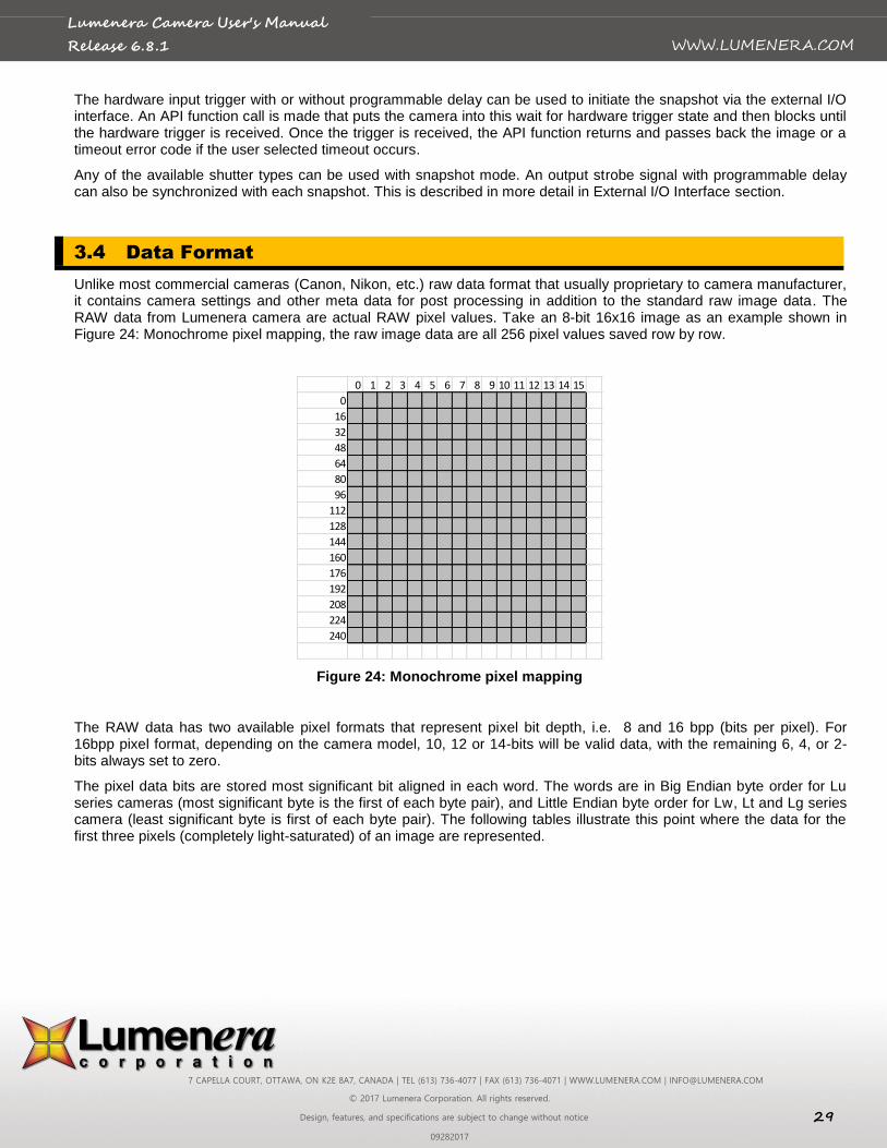
Unlike most commercial cameras (Canon, Nikon, etc.) raw data format that usually proprietary to camera manufacturer, it contains camera settings and other meta data for post processing in addition to the standard raw image data. The RAW data from Lumenera camera are actual RAW pixel values. Take an 8-bit 16x16 image as an example shown in Figure 24: Monochrome pixel mapping, the raw image data are all 256 pixel values saved row by row.
Figure 24: Monochrome pixel mapping
The RAW data has two available pixel formats that represent pixel bit depth, i.e. 8 and 16 bpp (bits per pixel). For 16bpp pixel format, depending on the camera model, 10, 12 or 14-bits will be valid data, with the remaining 6, 4, or 2-bits always set to zero.
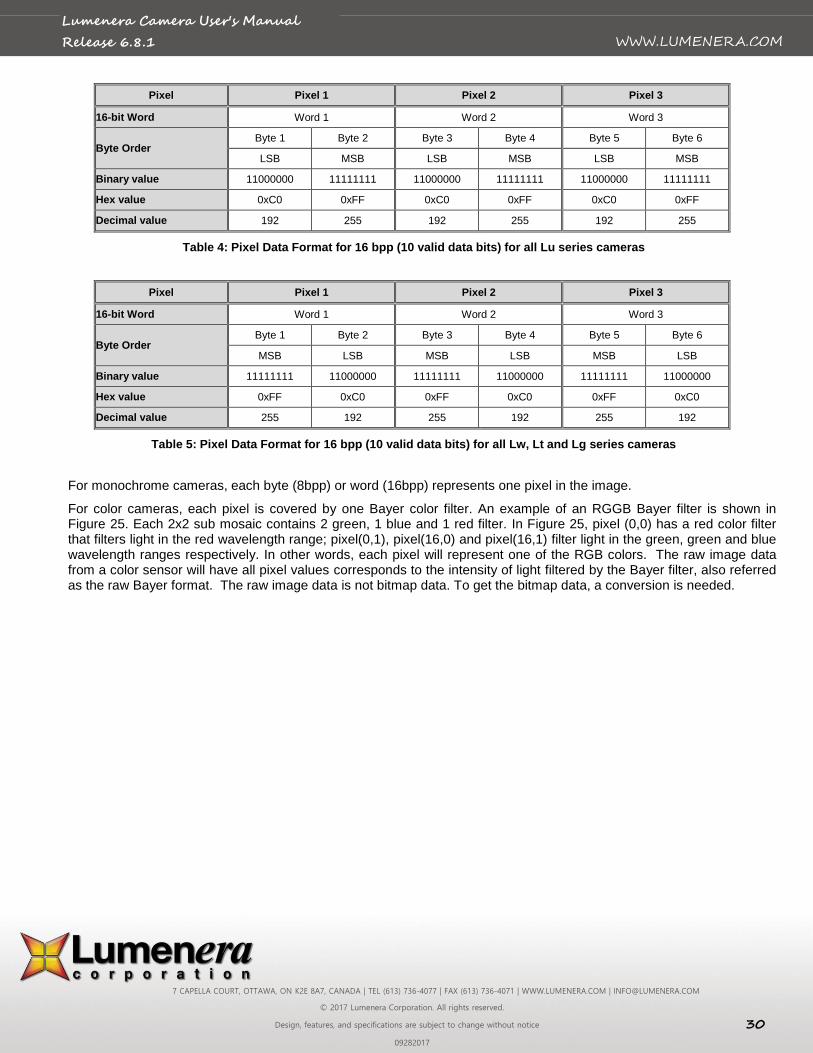
The pixel data bits are stored most significant bit aligned in each word. The words are in Big Endian byte order for Lu series cameras (most significant byte is the first of each byte pair), and Little Endian byte order for Lw, Lt and Lg series camera (least significant byte is first of each byte pair). The following tables illustrate this point where the data for the first three pixels (completely light-saturated) of an image are represented.
0 1 2 3 4 5 6 7 8 9 10 11 12 13 14 15
0
16
32
48
64
80
96
112
128
144
160
176
192
208
224
240
7 CAPELLA COURT, OTTAWA, ON K2E 8A7, CANADA | TEL (613) 736-4077 | FAX (613) 736-4071 | WWW.LUMENERA.COM | [email protected]
© 2017 Lumenera Corporation. All rights reserved.
Design, features, and specifications are subject to change without notice 30
09282017
WWW.LUMENERA.COM
Lumenera Camera User's Manual
Release 6.8.1
Pixel Pixel 1 Pixel 2 Pixel 3
16-bit Word Word 1 Word 2 Word 3
Byte Order Byte 1 Byte 2 Byte 3 Byte 4 Byte 5 Byte 6
LSB MSB LSB MSB LSB MSB
Binary value 11000000 11111111 11000000 11111111 11000000 11111111
Hex value 0xC0 0xFF 0xC0 0xFF 0xC0 0xFF
Decimal value 192 255 192 255 192 255
Table 4: Pixel Data Format for 16 bpp (10 valid data bits) for all Lu series cameras
Pixel Pixel 1 Pixel 2 Pixel 3
16-bit Word Word 1 Word 2 Word 3
Byte Order Byte 1 Byte 2 Byte 3 Byte 4 Byte 5 Byte 6
MSB LSB MSB LSB MSB LSB
Binary value 11111111 11000000 11111111 11000000 11111111 11000000
Hex value 0xFF 0xC0 0xFF 0xC0 0xFF 0xC0
Decimal value 255 192 255 192 255 192
Table 5: Pixel Data Format for 16 bpp (10 valid data bits) for all Lw, Lt and Lg series cameras
For monochrome cameras, each byte (8bpp) or word (16bpp) represents one pixel in the image.
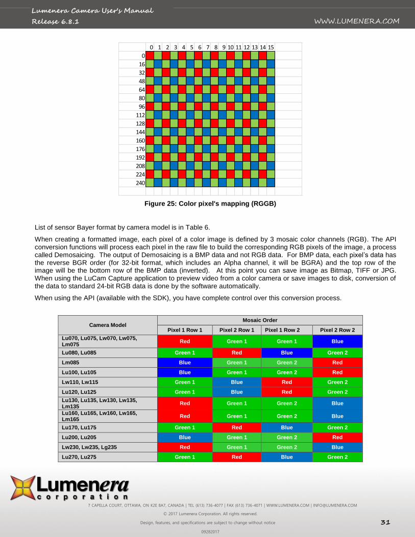
For color cameras, each pixel is covered by one Bayer color filter. An example of an RGGB Bayer filter is shown in Figure 25. Each 2x2 sub mosaic contains 2 green, 1 blue and 1 red filter. In Figure 25, pixel (0,0) has a red color filter that filters light in the red wavelength range; pixel(0,1), pixel(16,0) and pixel(16,1) filter light in the green, green and blue wavelength ranges respectively. In other words, each pixel will represent one of the RGB colors. The raw image data from a color sensor will have all pixel values corresponds to the intensity of light filtered by the Bayer filter, also referred as the raw Bayer format. The raw image data is not bitmap data. To get the bitmap data, a conversion is needed.
7 CAPELLA COURT, OTTAWA, ON K2E 8A7, CANADA | TEL (613) 736-4077 | FAX (613) 736-4071 | WWW.LUMENERA.COM | [email protected]
© 2017 Lumenera Corporation. All rights reserved.
Design, features, and specifications are subject to change without notice 31
09282017
WWW.LUMENERA.COM
Lumenera Camera User's Manual
Release 6.8.1
Figure 25: Color pixel's mapping (RGGB)
List of sensor Bayer format by camera model is in Table 6.
When creating a formatted image, each pixel of a color image is defined by 3 mosaic color channels (RGB). The API conversion functions will process each pixel in the raw file to build the corresponding RGB pixels of the image, a process called Demosaicing. The output of Demosaicing is a BMP data and not RGB data. For BMP data, each pixel’s data has the reverse BGR order (for 32-bit format, which includes an Alpha channel, it will be BGRA) and the top row of the image will be the bottom row of the BMP data (inverted). At this point you can save image as Bitmap, TIFF or JPG. When using the LuCam Capture application to preview video from a color camera or save images to disk, conversion of the data to standard 24-bit RGB data is done by the software automatically.
When using the API (available with the SDK), you have complete control over this conversion process.
Camera Model Mosaic Order
Pixel 1 Row 1 Pixel 2 Row 1 Pixel 1 Row 2 Pixel 2 Row 2
Lu070, Lu075, Lw070, Lw075, Lm075
Red Green 1 Green 1 Blue
Lu080, Lu085 Green 1 Red Blue Green 2
Lm085 Blue Green 1 Green 2 Red
Lu100, Lu105 Blue Green 1 Green 2 Red
Lw110, Lw115 Green 1 Blue Red Green 2
Lu120, Lu125 Green 1 Blue Red Green 2
Lu130, Lu135, Lw130, Lw135, Lm135
Red Green 1 Green 2 Blue
Lu160, Lu165, Lw160, Lw165, Lm165
Red Green 1 Green 2 Blue
Lu170, Lu175 Green 1 Red Blue Green 2
Lu200, Lu205 Blue Green 1 Green 2 Red
Lw230, Lw235, Lg235 Red Green 1 Green 2 Blue
Lu270, Lu275 Green 1 Red Blue Green 2
0 1 2 3 4 5 6 7 8 9 10 11 12 13 14 15
0
16
32
48
64
80
96
112
128
144
160
176
192
208
224
240
7 CAPELLA COURT, OTTAWA, ON K2E 8A7, CANADA | TEL (613) 736-4077 | FAX (613) 736-4071 | WWW.LUMENERA.COM | [email protected]
© 2017 Lumenera Corporation. All rights reserved.
Design, features, and specifications are subject to change without notice 32
09282017
WWW.LUMENERA.COM
Lumenera Camera User's Manual
Release 6.8.1
Camera Model Mosaic Order
Lw290, Lw295 Green 1 Blue Red Green 2
Lu370, Lu375 Green 1 Red Blue Green 2
Lw560, Lw565 Red Green 1 Green 2 Blue
Lw570, Lw575 Green 1 Red Blue Green 2
Lw620, Lw625 Green 1 Red Blue Green 2
Lw11050, Lw11056, Lw11057, Lw11058, Lw11059, Lm11059, Lg11059
Green 1 Red Blue Green 2
Lw16059 Green 1 Red Blue Green 2
Lt225, Lt425 Green 1 Red Blue Green 2
Lt345, Lt545, Lt945, Lt1245 Blue Green 2 Green 1 Red
Lt365, Lt965 Red Green 1 Green 2 Blue
Lt665, Lt16059H, Lt29059 Green 1 Red Blue Green 2
Lt1265R Green 1 Blue Red Green 2
Table 6: Bayer Data Color Mosaic Order
3.5 Subwindowing, Subsampling & Binning
Subwindowing, also known as region of interest (ROI), is the ability of the camera to output a smaller image size (subwindow) than the whole imager array. An imager that supports a maximum resolution of 1280 x 1024 pixels for example, could output a subwindow of 640 x 480 pixels with the subwindow being positioned nearly anywhere inside the 1280 x 1024. The subwindow is actually a smaller field of view than the maximum resolution available. There are limitations on the granularity of the subwindow size and on its position within the whole array. The granularity is 8 pixels.
Subsampling, also known as decimation, is the throwing away of every nth pixel or pixel pair in the image in the X and/or
Y directions. For example, an imager with a maximum resolution of 1280 x 1024 could throw away every second pixel in both the X and Y directions and output an image that is 640 x 512 pixels, yet covers the same field of view of the original full resolution. Not all cameras support Subsampling. Those that do may support subsample levels of 2, 4 or 8. Some cameras even allow different Subsampling in the X vs. the Y directions.
Binning is similar to Subsampling, except instead of throwing pixels away, pixel values are combined in some fashion. They can be either summed (to provide greater sensitivity) or averaged (to reduce noise). The resulting resolution would be the same as for Subsampling, but the data from every pixel is used. Several cameras support Binning with binning levels up to 8 by 8.
It is important to note that certain camera models do work in multi-tap configuration to give better speed performance and this need to be taken in consideration when working with sub window, subsampling or binning mode.
3.6 External I/O Interface
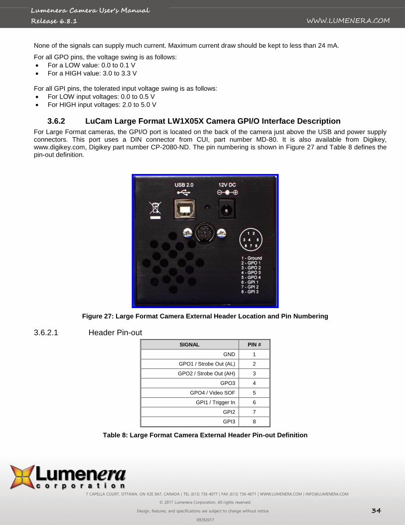
3.6.1 Standard LuCam Camera GPI/O Interface Description
For board-level cameras, the External Interface Header can be found in the corner of the PCB next to the silver USB connector. For enclosed cameras, it is found on the side of the camera near the USB connector. It is a male, 2 mm pitch, 16-pin (2 x 8) header. The pin numbering can be seen in Figure 26.

7 CAPELLA COURT, OTTAWA, ON K2E 8A7, CANADA | TEL (613) 736-4077 | FAX (613) 736-4071 | WWW.LUMENERA.COM | [email protected]
© 2017 Lumenera Corporation. All rights reserved.
Design, features, and specifications are subject to change without notice 33
09282017
WWW.LUMENERA.COM
Lumenera Camera User's Manual
Release 6.8.1
3.6.1.1 Recommended Mating Connectors
The following mating connectors have been tested to work with the cameras. All of them are for 16-pin (2 x 8), 2 mm pitch headers.
AMP/Tyco P/N 2-111626-5 IDC Ribbon Cable Receptacle
Molex GC/Waldom P/N 87568-1663 IDC Ribbon Cable Receptacle
Molex GC/Waldom P/N 87568-1693 IDC Ribbon Cable Receptacle Locking
For above mating connectors, 1 mm, 28 AWG stranded, round conductor flat cable is recommended.
Molex GC/Waldom 51110-1650 Wire Crimp Receptacle o Female Crimp Terminal for above – P/N 50394-8100
Norcomp P/N 2564-16-01RP2 Vertical Dual Row Receptacle
Sullins P/N PPWN082AFCN Vertical Dual Row Receptacle
All of these connectors can be purchased from Digi-Key® (www.digikey.com) but other parts suppliers may also carry
them.
Figure 26: External Header Location and Pin Numbering
3.6.1.2 Header Pin-out
SIGNAL PIN # PIN # SIGNAL
GPO1 / Strobe Out (AL) 1 2 GND
GPO2 / Strobe Out (AH) 3 4 GND
GPO3 5 6 GND
GPO4 / Video SOF 7 8 GND
GPI1 / Trigger In 9 10 GND
GPI2 11 12 GND
GPI3 13 14 GND
GPI4 15 16 GND or VCC Output (opt.)*
Table 7: Header Pin-out Definition
Note:* Certain camera models can be configured with alternate output for pin 16. In general, the Luxxx products with amber LED will have pin 16 connected to GND and Lw or Lu products with green LED will have this pin connected to VCC. Contact the Technical Assistance Centre for details or confirming the current configuration of this pin.
7 CAPELLA COURT, OTTAWA, ON K2E 8A7, CANADA | TEL (613) 736-4077 | FAX (613) 736-4071 | WWW.LUMENERA.COM | [email protected]
© 2017 Lumenera Corporation. All rights reserved.
Design, features, and specifications are subject to change without notice 34
09282017
WWW.LUMENERA.COM
Lumenera Camera User's Manual
Release 6.8.1
None of the signals can supply much current. Maximum current draw should be kept to less than 24 mA.
For all GPO pins, the voltage swing is as follows:
For a LOW value: 0.0 to 0.1 V
For a HIGH value: 3.0 to 3.3 V
For all GPI pins, the tolerated input voltage swing is as follows:
For LOW input voltages: 0.0 to 0.5 V
For HIGH input voltages: 2.0 to 5.0 V
3.6.2 LuCam Large Format LW1X05X Camera GPI/O Interface Description
For Large Format cameras, the GPI/O port is located on the back of the camera just above the USB and power supply connectors. This port uses a DIN connector from CUI, part number MD-80. It is also available from Digikey, www.digikey.com, Digikey part number CP-2080-ND. The pin numbering is shown in Figure 27 and Table 8 defines the pin-out definition.
Figure 27: Large Format Camera External Header Location and Pin Numbering
3.6.2.1 Header Pin-out
SIGNAL PIN #
GND 1
GPO1 / Strobe Out (AL) 2
GPO2 / Strobe Out (AH) 3
GPO3 4
GPO4 / Video SOF 5
GPI1 / Trigger In 6
GPI2 7
GPI3 8
Table 8: Large Format Camera External Header Pin-out Definition
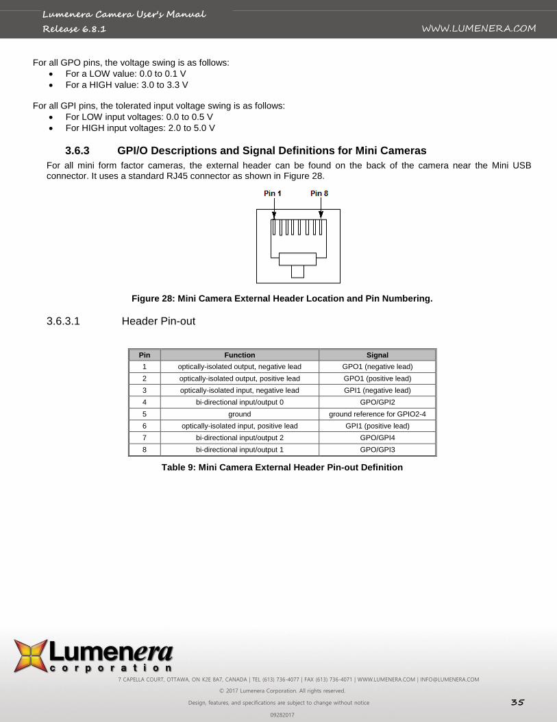
7 CAPELLA COURT, OTTAWA, ON K2E 8A7, CANADA | TEL (613) 736-4077 | FAX (613) 736-4071 | WWW.LUMENERA.COM | [email protected]
© 2017 Lumenera Corporation. All rights reserved.
Design, features, and specifications are subject to change without notice 35
09282017
WWW.LUMENERA.COM
Lumenera Camera User's Manual
Release 6.8.1
For all GPO pins, the voltage swing is as follows:
For a LOW value: 0.0 to 0.1 V
For a HIGH value: 3.0 to 3.3 V
For all GPI pins, the tolerated input voltage swing is as follows:
For LOW input voltages: 0.0 to 0.5 V
For HIGH input voltages: 2.0 to 5.0 V
3.6.3 GPI/O Descriptions and Signal Definitions for Mini Cameras
For all mini form factor cameras, the external header can be found on the back of the camera near the Mini USB connector. It uses a standard RJ45 connector as shown in Figure 28.
Figure 28: Mini Camera External Header Location and Pin Numbering.
3.6.3.1 Header Pin-out
Pin Function Signal
1 optically-isolated output, negative lead GPO1 (negative lead)
2 optically-isolated output, positive lead GPO1 (positive lead)
3 optically-isolated input, negative lead GPI1 (negative lead)
4 bi-directional input/output 0 GPO/GPI2
5 ground ground reference for GPIO2-4
6 optically-isolated input, positive lead GPI1 (positive lead)
7 bi-directional input/output 2 GPO/GPI4
8 bi-directional input/output 1 GPO/GPI3
Table 9: Mini Camera External Header Pin-out Definition
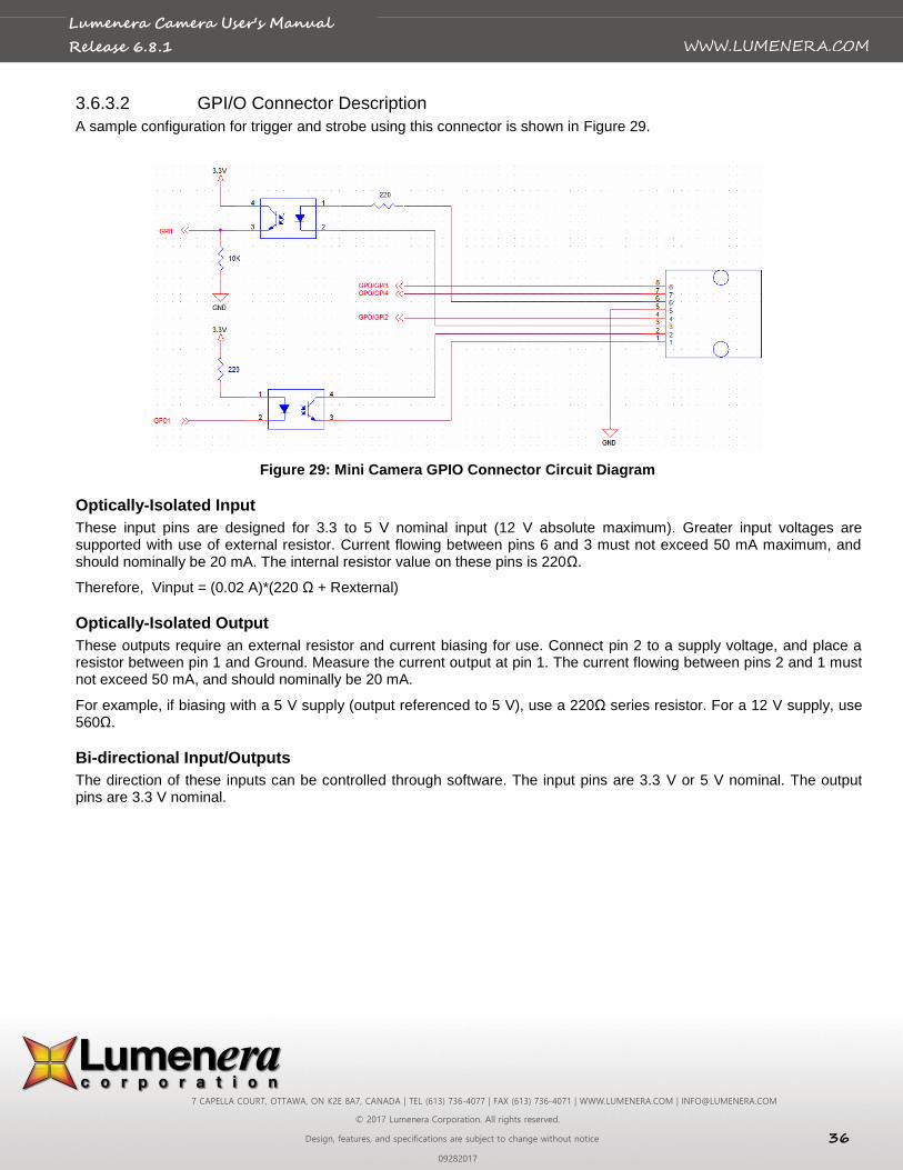
7 CAPELLA COURT, OTTAWA, ON K2E 8A7, CANADA | TEL (613) 736-4077 | FAX (613) 736-4071 | WWW.LUMENERA.COM | [email protected]
© 2017 Lumenera Corporation. All rights reserved.
Design, features, and specifications are subject to change without notice 36
09282017
WWW.LUMENERA.COM
Lumenera Camera User's Manual
Release 6.8.1
3.6.3.2 GPI/O Connector Description
A sample configuration for trigger and strobe using this connector is shown in Figure 29.
Figure 29: Mini Camera GPIO Connector Circuit Diagram
Optically-Isolated Input
These input pins are designed for 3.3 to 5 V nominal input (12 V absolute maximum). Greater input voltages are supported with use of external resistor. Current flowing between pins 6 and 3 must not exceed 50 mA maximum, and should nominally be 20 mA. The internal resistor value on these pins is 220Ω.
Therefore, Vinput = (0.02 A)*(220 Ω + Rexternal)
Optically-Isolated Output
These outputs require an external resistor and current biasing for use. Connect pin 2 to a supply voltage, and place a resistor between pin 1 and Ground. Measure the current output at pin 1. The current flowing between pins 2 and 1 must not exceed 50 mA, and should nominally be 20 mA.
For example, if biasing with a 5 V supply (output referenced to 5 V), use a 220Ω series resistor. For a 12 V supply, use 560Ω.
Bi-directional Input/Outputs
The direction of these inputs can be controlled through software. The input pins are 3.3 V or 5 V nominal. The output pins are 3.3 V nominal.
7 CAPELLA COURT, OTTAWA, ON K2E 8A7, CANADA | TEL (613) 736-4077 | FAX (613) 736-4071 | WWW.LUMENERA.COM | [email protected]
© 2017 Lumenera Corporation. All rights reserved.
Design, features, and specifications are subject to change without notice 37
09282017
WWW.LUMENERA.COM
Lumenera Camera User's Manual
Release 6.8.1
3.6.3.3 GPI/O Input and Output Port Tolerances
Optically-isolated Input:
Nominal voltage: 5 V
Maximum voltage: 12 V
Threshold voltage for input to be considered high is approximately 0.55 V
Note: The maximum can be increased with an external resistor, as described in Section 0.
Optically-isolated Output:
Output requires an external resistor
Maximum voltage depends on the external resistor value
Note: Maximum current that can be provided from the output port is 50 mA.
Bi-directional I/O:
Nominal voltage can be either 3.3 V or 5 V
Maximum voltage: 5 V
Minimum threshold for input to be considered high is approximately 2 V
Maximum threshold for an input to be considered low is approximately 0.8 V
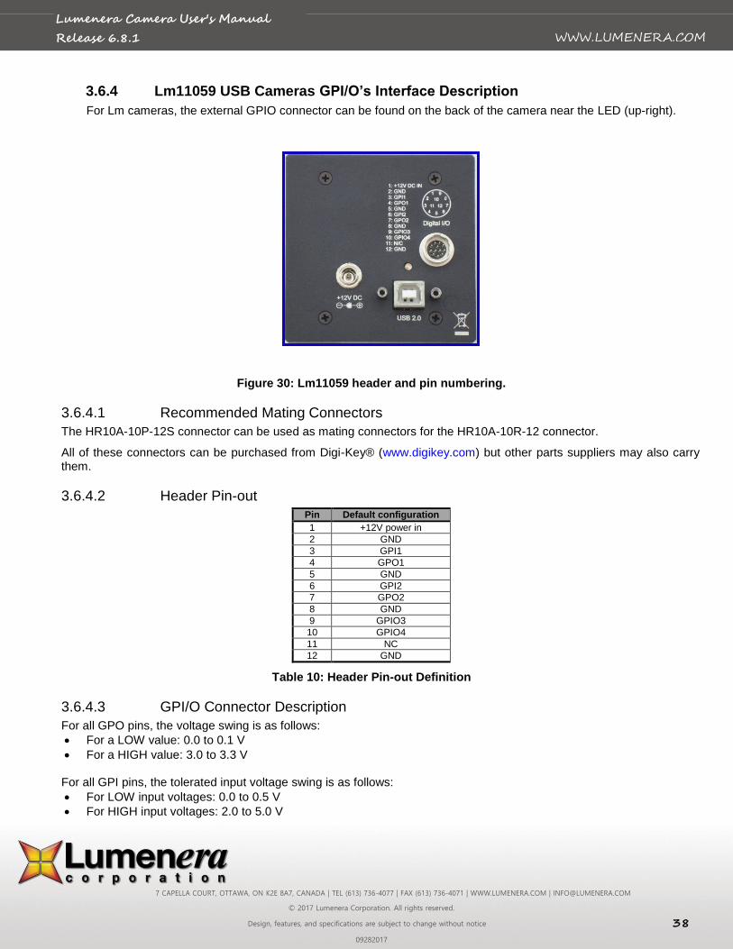
7 CAPELLA COURT, OTTAWA, ON K2E 8A7, CANADA | TEL (613) 736-4077 | FAX (613) 736-4071 | WWW.LUMENERA.COM | [email protected]
© 2017 Lumenera Corporation. All rights reserved.
Design, features, and specifications are subject to change without notice 38
09282017
WWW.LUMENERA.COM
Lumenera Camera User's Manual
Release 6.8.1
3.6.4 Lm11059 USB Cameras GPI/O’s Interface Description
For Lm cameras, the external GPIO connector can be found on the back of the camera near the LED (up-right).
Figure 30: Lm11059 header and pin numbering.
3.6.4.1 Recommended Mating Connectors
The HR10A-10P-12S connector can be used as mating connectors for the HR10A-10R-12 connector.
All of these connectors can be purchased from Digi-Key® (www.digikey.com) but other parts suppliers may also carry them.
3.6.4.2 Header Pin-out
Pin Default configuration
1 +12V power in
2 GND
3 GPI1
4 GPO1
5 GND
6 GPI2
7 GPO2
8 GND
9 GPIO3
10 GPIO4
11 NC
12 GND
Table 10: Header Pin-out Definition
3.6.4.3 GPI/O Connector Description
For all GPO pins, the voltage swing is as follows:
For a LOW value: 0.0 to 0.1 V
For a HIGH value: 3.0 to 3.3 V
For all GPI pins, the tolerated input voltage swing is as follows:
For LOW input voltages: 0.0 to 0.5 V
For HIGH input voltages: 2.0 to 5.0 V
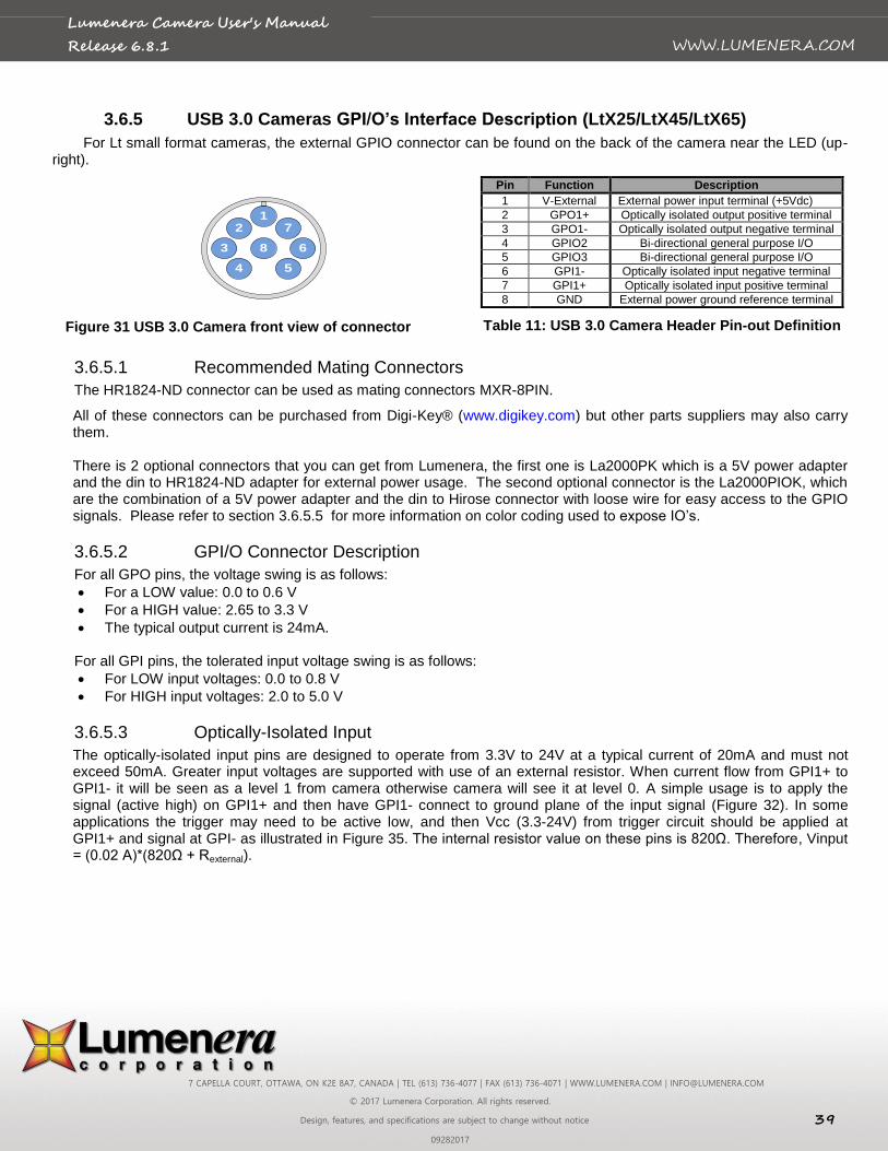
7 CAPELLA COURT, OTTAWA, ON K2E 8A7, CANADA | TEL (613) 736-4077 | FAX (613) 736-4071 | WWW.LUMENERA.COM | [email protected]
© 2017 Lumenera Corporation. All rights reserved.
Design, features, and specifications are subject to change without notice 39
09282017
WWW.LUMENERA.COM
Lumenera Camera User's Manual
Release 6.8.1
3.6.5 USB 3.0 Cameras GPI/O’s Interface Description (LtX25/LtX45/LtX65)
For Lt small format cameras, the external GPIO connector can be found on the back of the camera near the LED (up-right).
12
3
4 5
6
7
8
Figure 31 USB 3.0 Camera front view of connector
Pin Function Description
1 V-External External power input terminal (+5Vdc)
2 GPO1+ Optically isolated output positive terminal
3 GPO1- Optically isolated output negative terminal
4 GPIO2 Bi-directional general purpose I/O
5 GPIO3 Bi-directional general purpose I/O
6 GPI1- Optically isolated input negative terminal
7 GPI1+ Optically isolated input positive terminal
8 GND External power ground reference terminal
Table 11: USB 3.0 Camera Header Pin-out Definition
3.6.5.1 Recommended Mating Connectors
The HR1824-ND connector can be used as mating connectors MXR-8PIN.
All of these connectors can be purchased from Digi-Key® (www.digikey.com) but other parts suppliers may also carry them. There is 2 optional connectors that you can get from Lumenera, the first one is La2000PK which is a 5V power adapter and the din to HR1824-ND adapter for external power usage. The second optional connector is the La2000PIOK, which are the combination of a 5V power adapter and the din to Hirose connector with loose wire for easy access to the GPIO signals. Please refer to section 3.6.5.5 for more information on color coding used to expose IO’s.
3.6.5.2 GPI/O Connector Description
For all GPO pins, the voltage swing is as follows:
For a LOW value: 0.0 to 0.6 V
For a HIGH value: 2.65 to 3.3 V
The typical output current is 24mA.
For all GPI pins, the tolerated input voltage swing is as follows:
For LOW input voltages: 0.0 to 0.8 V
For HIGH input voltages: 2.0 to 5.0 V
3.6.5.3 Optically-Isolated Input
The optically-isolated input pins are designed to operate from 3.3V to 24V at a typical current of 20mA and must not exceed 50mA. Greater input voltages are supported with use of an external resistor. When current flow from GPI1+ to GPI1- it will be seen as a level 1 from camera otherwise camera will see it at level 0. A simple usage is to apply the signal (active high) on GPI1+ and then have GPI1- connect to ground plane of the input signal (Figure 32). In some applications the trigger may need to be active low, and then Vcc (3.3-24V) from trigger circuit should be applied at GPI1+ and signal at GPI- as illustrated in Figure 35. The internal resistor value on these pins is 820Ω. Therefore, Vinput = (0.02 A)*(820Ω + Rexternal).
7 CAPELLA COURT, OTTAWA, ON K2E 8A7, CANADA | TEL (613) 736-4077 | FAX (613) 736-4071 | WWW.LUMENERA.COM | [email protected]
© 2017 Lumenera Corporation. All rights reserved.
Design, features, and specifications are subject to change without notice 40
09282017
WWW.LUMENERA.COM
Lumenera Camera User's Manual
Release 6.8.1
Figure 32: Active High Example
Figure 33: Active Low Example
3.6.5.4 Optically-Isolated Output
The optically-isolated output requires an external resistor and biasing current. The current flow between collector and emitter should nominally be 20mA and must not exceed 50 mA. For example, for biasing with a 5V supply (output referenced to 5V), use a 220Ω series resistor. For a 12V supply, use 560Ω. There are 2 common configuration can be used for outputs, active high or active low output signal. Active high output, will produce and output level to VCC when the LED in the opto-coupler is on (Figure 34). Figure 35 demonstrate how to configure the GPO1 to output 0 when signal is active.
Figure 34: Active High output
Figure 35: Active Low Output
7 CAPELLA COURT, OTTAWA, ON K2E 8A7, CANADA | TEL (613) 736-4077 | FAX (613) 736-4071 | WWW.LUMENERA.COM | [email protected]
© 2017 Lumenera Corporation. All rights reserved.
Design, features, and specifications are subject to change without notice 41
09282017
WWW.LUMENERA.COM
Lumenera Camera User's Manual
Release 6.8.1
3.6.5.5 La2000PIOK optional connector pin-out information.
The La2000PIOK provide the ability to use external power and easy access of the GPIO signals for USB 3.0 (Lt's) camera model.
Pin # Function Wire color Description
1 V-External RED External power input terminal (+5Vdc)
2 GPO1+ GREEN Optically isolated output positive terminal
3 GPO1- ORANGE Optically isolated output negative terminal
4 GPIO2 BLUE Bi-directional general purpose I/O
5 GPIO3 BROWN Bi-directional general purpose I/O
6 GPI1- YELLOW Optically isolated input negative terminal
7 GPI1+ GREY Optically isolated input positive terminal
8 GND BLACK External power ground reference terminal
Table 12 La2000PIOK Wire color definition
3.6.6 Lt16059H & LT29059 GPI/O’s Interface Description
The external GPIO connector can be found on the back of the camera near the LED (up-right).
3.6.6.1 Recommended Mating Connectors
The HR10A-10R-12S(71) connector can be used as mating connectors to Hirose HR10A-10R-12PB (71).
All of these connectors can be purchased from Digi-Key® (www.digikey.com) but other parts suppliers may also carry them. There is an optional dongle that you can get from Lumenera, the first one is La3000PAFL which is the combination of a 12V power adapter and the din to Hirose connector with loose wire for easy access to the GPIO signals. Please refer to section 3.6.6.5 for more information on color coding used to expose IO’s.
Pin Function Description
1 V-External External power input terminal (+12Vdc)
2 GND Ground
3 GPI1+ Optically isolated input positive terminal
4 GPO1+ Optically isolated output positive terminal
5 GND Ground
6 GPI1- Optically isolated input negative terminal
7 GPO1- Optically isolated output negative terminal
8 GND Ground
9 GPIO3 Bi-directional general purpose I/O
10 GPIO4 Bi-directional general purpose I/O
11 NC Not Connected
12 GND Ground
Table 13 USB 3.0 Camera Header Pin-out Definition
Figure 36 Camera front view of connector
7 CAPELLA COURT, OTTAWA, ON K2E 8A7, CANADA | TEL (613) 736-4077 | FAX (613) 736-4071 | WWW.LUMENERA.COM | [email protected]
© 2017 Lumenera Corporation. All rights reserved.
Design, features, and specifications are subject to change without notice 42
09282017
WWW.LUMENERA.COM
Lumenera Camera User's Manual
Release 6.8.1
3.6.6.2 GPI/O Connector Description
For all GPO pins, the voltage swing is as follows:
For a LOW value: 0.0 to 0.6 V
For a HIGH value: 2.65 to 3.3 V
The typical output current is 24mA.
For all GPI pins, the tolerated input voltage swing is as follows:
For LOW input voltages: 0.0 to 0.8 V
For HIGH input voltages: 2.0 to 5.0 V
3.6.6.3 Optically-Isolated Input
The optically-isolated input pins are designed to operate from 3.3V to 24V at a typical current of 20mA and must not exceed 50mA. Greater input voltages are supported with use of an external resistor. When current flow from GPI1+ to GPI1- it will be seen as a level 1 from camera otherwise camera will see it at level 0. A simple usage is to apply the signal (active high) on GPI1+ and then have GPI1- connect to ground plane of the input signal (Figure 32). In some applications the trigger may need to be active low, and then Vcc (3.3-24V) from trigger circuit should be applied at GPI1+ and signal at GPI- as illustrated in Figure 35. The internal resistor value on these pins is 820Ω. Therefore, Vinput = (0.02 A)*(820Ω + Rexternal).
3.6.6.4 Optically-Isolated Output
The optically-isolated output requires an external resistor and biasing current. The current flow between collector and emitter should nominally be 20mA and must not exceed 50 mA. For example, for biasing with a 5V supply (output referenced to 5V), use a 220Ω series resistor. For a 12V supply, use 560Ω. There are 2 common configuration can be used for outputs, active high or active low output signal. Active high output, will produce and output level to VCC when the LED in the opto-coupler is on (Figure 34). Figure 35 demonstrate how to configure the GPO1 to output 0 when signal is active.
3.6.6.5 La3000PAFL optional connector pin-out information.
The La3000PAFL provide the ability to use external power and easy access of the GPIO signals for USB 3.0 Lt16059H and Lt29059 camera model.
Pin # Function Wire color Description
1 V-External RED External power input terminal (+12Vdc)
2 GND White Ground
3 GPI1+ GREY Optically isolated input positive terminal
4 GPO1+ GREEN Optically isolated output positive terminal
5 GND PINK Ground
6 GPI1- YELLOW Optically isolated input negative terminal
7 GPO1- ORANGE Optically isolated output negative terminal
8 GND BLACK Ground
9 GPIO3 BLUE Bi-directional general purpose I/O
10 GPIO4 BROWN Bi-directional general purpose I/O
11 NC TAN Not Connected
12 GND VIOLET Ground
Table 14 La3000PAFL Wire color definition
7 CAPELLA COURT, OTTAWA, ON K2E 8A7, CANADA | TEL (613) 736-4077 | FAX (613) 736-4071 | WWW.LUMENERA.COM | [email protected]
© 2017 Lumenera Corporation. All rights reserved.
Design, features, and specifications are subject to change without notice 43
09282017
WWW.LUMENERA.COM
Lumenera Camera User's Manual
Release 6.8.1
3.6.7 Gigabit Cameras GPI/O’s Interface Description
For Lg cameras, the external header can be found on the back of the camera near the GigE connector.
Figure 37: Lg Camera External Header Location and Pin Numbering
3.6.7.1 Recommended Mating Connectors
The HR10A-10P-12S connector can be used as mating connectors for the HR10A-10R-12 connector.
All of these connectors can be purchased from Digi-Key® (www.digikey.com) but other parts suppliers may also carry them.
3.6.7.2 Header Pin-out
Pin Default configuration
1 NC
2 GND
3 GPI1
4 GPO1
5 GND
6 GPI2
7 GPO2
8 GND
9 GPIO1
10 GPIO2
11 NC
12 GND
Table 15: Header Pin-out Definition
3.6.7.3 GPI/O Connector Description
For all GPO pins, the voltage swing is as follows:
For a LOW value: 0.0 to 0.1 V
For a HIGH value: 3.0 to 3.3 V
For all GPI pins, the tolerated input voltage swing is as follows:
For LOW input voltages: 0.0 to 0.5 V
3.6.8 For HIGH input voltages: 2.0 to 5.0 VUSB Tether Connector
Some board level models have a connector to enable use of a 5 pins flat connector (Figure 38) for the USB connection. For the signal voltages, please refer to USB 2.0 specifications. Table 16 describes the connector signal configuration.
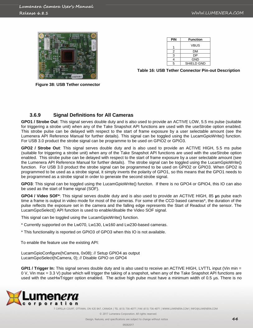
7 CAPELLA COURT, OTTAWA, ON K2E 8A7, CANADA | TEL (613) 736-4077 | FAX (613) 736-4071 | WWW.LUMENERA.COM | [email protected]
© 2017 Lumenera Corporation. All rights reserved.
Design, features, and specifications are subject to change without notice 44
09282017
WWW.LUMENERA.COM
Lumenera Camera User's Manual
Release 6.8.1
Figure 38: USB Tether connector
PIN Function
1
VBUS
2 DM
3 DP
4 GND
5 SHIELD GND
Table 16: USB Tether Connector Pin-out Description
3.6.9 Signal Definitions for All Cameras
GPO1 / Strobe Out: This signal serves double duty and is also used to provide an ACTIVE LOW, 5.5 ms pulse (suitable for triggering a strobe unit) when any of the Take Snapshot API functions are used with the useStrobe option enabled. This strobe pulse can be delayed with respect to the start of frame exposure by a user selectable amount (see the Lumenera API Reference Manual for further details). This signal can be toggled using the LucamGpioWrite() function. For USB 3.0 product the strobe signal can be programme to be used on GPIO2 or GPIO3.
GPO2 / Strobe Out: This signal serves double duty and is also used to provide an ACTIVE HIGH, 5.5 ms pulse (suitable for triggering a strobe unit) when any of the Take Snapshot API functions are used with the useStrobe option enabled. This strobe pulse can be delayed with respect to the start of frame exposure by a user selectable amount (see the Lumenera API Reference Manual for further details). The strobe signal can be toggled using the LucamGpioWrite() function. For USB 3.0 product the strobe signal can be programmed to be used on GPIO2 or GPIO3. When GPO2 is programmed to be used as a strobe signal, it simply inverts the polarity of GPO1, so this means that the GPO1 needs to be programmed as a strobe signal in order to generate the second strobe signal.
GPO3: This signal can be toggled using the LucamGpioWrite() function. If there is no GPO4 or GPIO4, this IO can also be used as the start of frame signal (SOF).
GPO4 / Video SOF*: This signal serves double duty and is also used to provide an ACTIVE HIGH, 85 μs pulse each time a frame is output in video mode for most of the cameras. For some of the CCD based cameras*, the duration of the pulse reflects the exposure set in the camera and the falling edge represents the Start of Readout of the sensor. The LucamGpoSelect() API function is used to enable/disable the Video SOF signal.
This signal can be toggled using the LucamGpioWrite() function.
* Currently supported on the Lw070, Lw130, Lw160 and Lw230-based cameras.
* This functionality is reported on GPIO3 of GPO3 when this IO is not available.
To enable the feature use the existing API:
LucamGpioConfigure(hCamera, 0x08); // Setup GPIO4 as output LucamGpoSelect(hCamera, 0); // Disable GPIO on GPO4
GPI1 / Trigger In: This signal serves double duty and is also used to receive an ACTIVE HIGH, LVTTL input (Vin min = 0 V, Vin max = 3.3 V) pulse which will trigger the taking of a snapshot, when any of the Take Snapshot API functions are used with the useHwTrigger option enabled. The active high pulse must have a minimum width of 0.5 μs. There is no
7 CAPELLA COURT, OTTAWA, ON K2E 8A7, CANADA | TEL (613) 736-4077 | FAX (613) 736-4071 | WWW.LUMENERA.COM | [email protected]
© 2017 Lumenera Corporation. All rights reserved.
Design, features, and specifications are subject to change without notice 45
09282017
WWW.LUMENERA.COM
Lumenera Camera User's Manual
Release 6.8.1
maximum limit to the trigger pulse width. This signal is floating and MUST be driven at all times when being used. The signal status can be obtained by using the LucamGpioRead() function.
GPI2: This signal is floating and MUST be driven at all times when being used. The signal status can be obtained by using the LucamGpioRead()function.
GPI3: This signal is floating and MUST be driven at all times when being used. The signal status can be obtained by using the LucamGpioRead() function.
GPI4: This signal is floating and MUST be driven at all times when being used. The signal status can be obtained by using the LucamGpioRead() function.
VCC Output: This optional feature allows the camera to output a 3.3 V DC signal on Pin 16. The camera can source up to 50 mA of current from this pin. This feature is only available on Lw-based cameras that have been ordered with this option available. This feature is not available on existing Lu-based cameras. The large format cameras, mini cameras and GigE Vision cameras do not have this signal available on the external I/O connector.
GPIO2: Ready Signal
The ready signal is an output signal that is raised when camera is ready to accept trigger. This signal only has meaning when using camera with hardware trigger, however it will still produce when using camera in software trigger. The signal will be available on GPIO2, so GPIO2 pin need to be configure as an output. In order for the signal to work, the trigger polarity need to be set so trigger are intercepted on rising edge. This signal does not interfere with the SOF signal, so it is possible to have the Ready signal and the SOF signal at the same time.
The signal is supported by listed product: Lt345, Lt545, Lt945, Lt1245, Lt365, Lt665, Lt965, Lt1265, Lt16059, Lt29059, Lt425 To enable the feature use the existing API: LucamGpioConfigure(hCamera, 0x02); // Setup GPO2 as output LucamGpoSelect(hCamera, 0); // Disable GPIO on GPO2
3.6.10 Taking a Single-Frame Snapshot with the Camera External I/O Interface
The Lumenera LuCam API makes use of several of the External Interface Header pins automatically; when the Take Snapshot related functions (those that use the LUCAM_SNAPSHOT structure) are called with certain options (see the LuCam API documentation for more details). The LUCAM_SNAPSHOT structure allows the setting of the following parameters that control the taking of a snapshot and the timing of triggers:
Trigger Mode (useHwTrigger): There are two types of snapshot triggering, hardware and software. When enabled, the snapshot will be triggered when the trigger input signal is detected after a Take Snapshot API is called (the API blocks until it times out or until the trigger occurs and the frame of data is returned). When disabled, the API function itself triggers the snapshot and returns the frame of data. The hardware trigger is expected on Pin 9 of the External Interface Header as described above. The software trigger is initiated from within the API Take Snapshot functions (for more details see the API documentation.)
Trigger Delay (exposureDelay): A delay in milliseconds from the trigger (hardware or software) to the start of frame exposure can be set.
Strobe Mode (useStrobe): In concert with either triggering mode, a user may also trigger an external strobe light synchronized to the frame exposure. When this parameter is enabled, the strobe signal pulse will be initiated on Pins 1 and 3 as described above. In this case, a strobe delay should be defined.
Strobe Delay (strobeDelay): A delay in milliseconds from the trigger (hardware or software) to the strobe pulse (rising edge for ACTIVE HIGH, falling edge for ACTIVE LOW) can be set.
Exposure Time (exposure): The length of time in milliseconds to expose the image before readout begins.
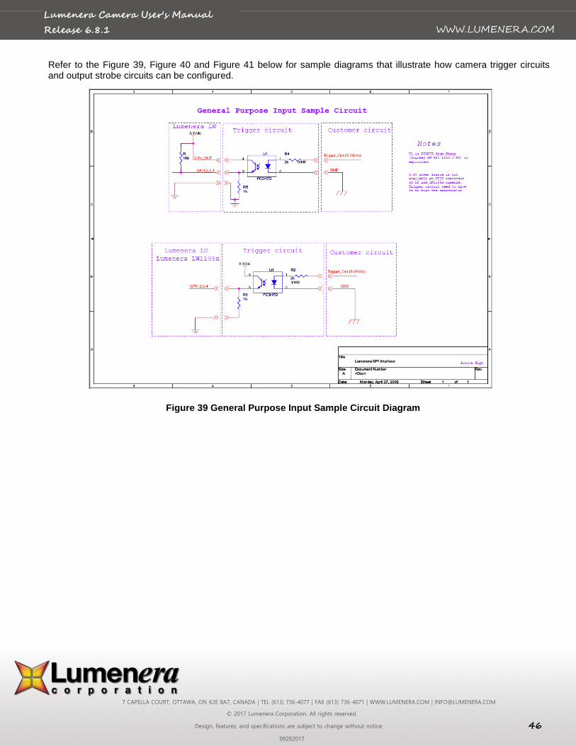
7 CAPELLA COURT, OTTAWA, ON K2E 8A7, CANADA | TEL (613) 736-4077 | FAX (613) 736-4071 | WWW.LUMENERA.COM | [email protected]
© 2017 Lumenera Corporation. All rights reserved.
Design, features, and specifications are subject to change without notice 46
09282017
WWW.LUMENERA.COM
Lumenera Camera User's Manual
Release 6.8.1
Refer to the Figure 39, Figure 40 and Figure 41 below for sample diagrams that illustrate how camera trigger circuits and output strobe circuits can be configured.
Figure 34: General Purpose Input Sample Circuit Diagram Figure 39 General Purpose Input Sample Circuit Diagram
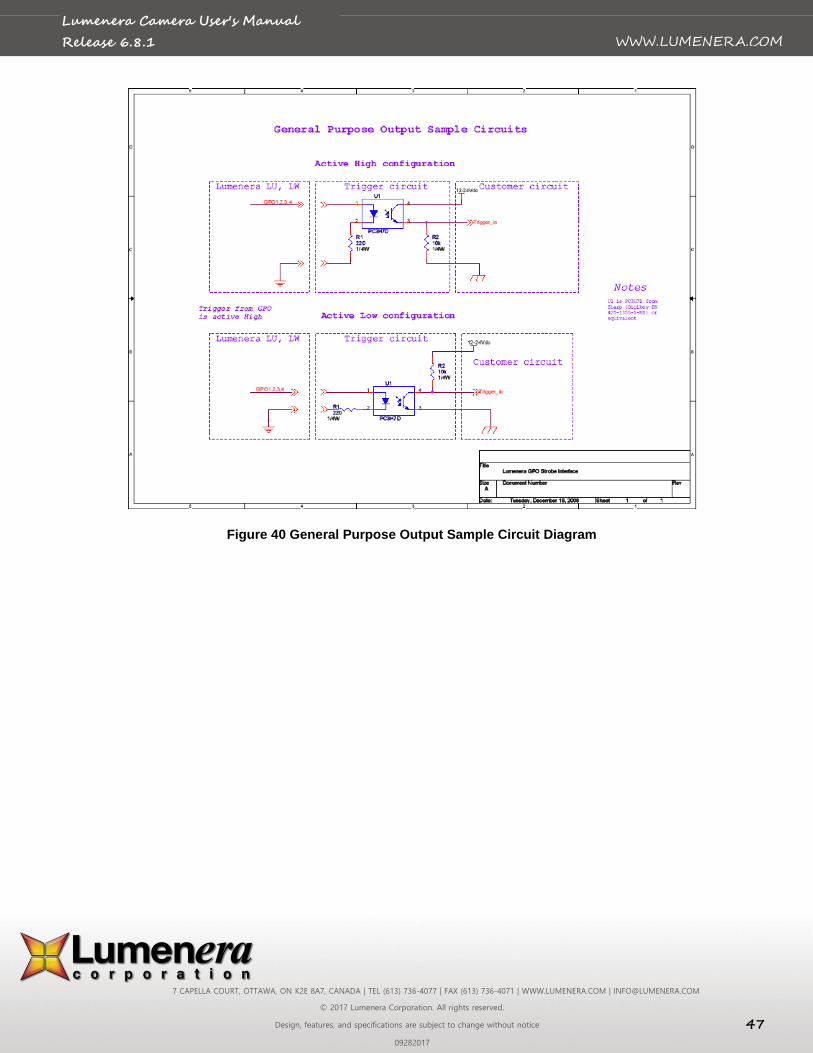
7 CAPELLA COURT, OTTAWA, ON K2E 8A7, CANADA | TEL (613) 736-4077 | FAX (613) 736-4071 | WWW.LUMENERA.COM | [email protected]
© 2017 Lumenera Corporation. All rights reserved.
Design, features, and specifications are subject to change without notice 47
09282017
WWW.LUMENERA.COM
Lumenera Camera User's Manual
Release 6.8.1
Figure 35: General Purpose Output Sample Circuit Diagram Figure 40 General Purpose Output Sample Circuit Diagram

7 CAPELLA COURT, OTTAWA, ON K2E 8A7, CANADA | TEL (613) 736-4077 | FAX (613) 736-4071 | WWW.LUMENERA.COM | [email protected]
© 2017 Lumenera Corporation. All rights reserved.
Design, features, and specifications are subject to change without notice 48
09282017
WWW.LUMENERA.COM
Lumenera Camera User's Manual
Release 6.8.1
Figure 41 Simple Flash Sample Circuit Diagram
7 CAPELLA COURT, OTTAWA, ON K2E 8A7, CANADA | TEL (613) 736-4077 | FAX (613) 736-4071 | WWW.LUMENERA.COM | [email protected]
© 2017 Lumenera Corporation. All rights reserved.
Design, features, and specifications are subject to change without notice 49
09282017
WWW.LUMENERA.COM
Lumenera Camera User's Manual
Release 6.8.1
3.7 External Power
Most camera models are powered exclusively via the USB cable, which nominally supplies 5 Volts. Large format camera models (eg: Lw11059, Lw16059) require an external 12V power adapter. A power adapter can also be used to power the camera, in cases where the USB cable does not supply power (e.g. from a Laptop computer or non-powered USB hub.)
The GigE Vision camera models require an external 12V power adapter at all time.
The appropriate external power adapter for your camera can be purchased directly from Lumenera. The Lumenera power adapter part number for your camera can be found in camera datasheet on the Lumenera website (www.lumenera.com) Product tools, in the universal power guide
(http://www.lumenera.com/media/wysiwyg/support/pdf/PowerSuppliesPMN.pdf)
or you can contact Lumenera Technical Assistance team ([email protected]). The usage of a universal power adapter is also possible and this component must adhere to the following specifications:
Lu series cameras:
1. 6 Volts DC Regulated
2. 1000mA Minimum Current rating
3. 2.1mm Tip
4. Center Positive (+)
Lw series cameras: 1. 5 Volts DC Regulated
2. 500mA Minimum Current Rating
3. 2.1mm Tip
4. Center Positive (+)
Exception: Lw110 uses a 6 V DC power adapter when USB power is insufficient.
Lt Series cameras ( small format):
1. 5 Volts DC Regulated
2. Lt225/Lt425: 1000mA Minimum Curent rating
Lt365/Lt665/Lt965/Lt1265: 2.5A Minimum Current rating
Lt345/Lt545/Lt945/Lt1245: do not required external power on USB 3.0 port but a 5-24V +/- 7.5% 2A external power is required when connecting to USB 2.0 port or USB hub that cannot deliver power.
3. Refer to section 3.6.5 for the mating GPIO connector and pin-out to supply external power
Lt16059H & Lt29059 Large format camera:
1. 12 Volts DC Regulated.
2. 2.0A Minimum Current Rating.
3. 2.1mm tip.
4. Center Positive (+)
Large format cameras (LW1105x, LW62x): 1. 12 Volts DC Regulated
2. 2A Minimum Current Rating
3. 2.1mm Tip
4. Center Positive (+)
Lg series cameras: 1. 12 Volts DC Regulated
2. 2A Minimum Current Rating
3. 2.1mm Tip
4. Center Positive (+)
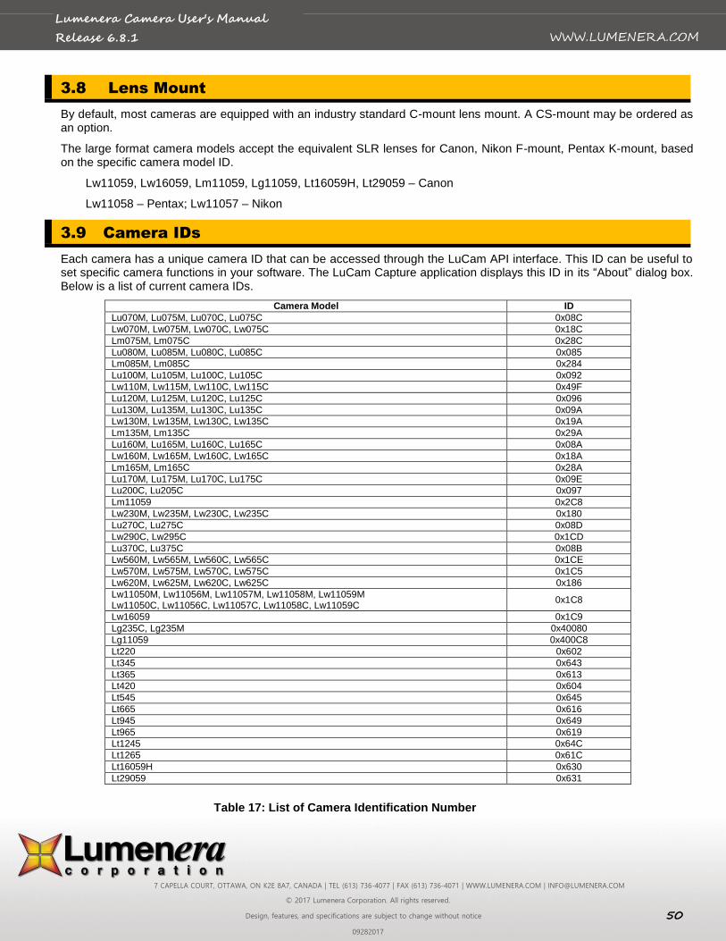
7 CAPELLA COURT, OTTAWA, ON K2E 8A7, CANADA | TEL (613) 736-4077 | FAX (613) 736-4071 | WWW.LUMENERA.COM | [email protected]
© 2017 Lumenera Corporation. All rights reserved.
Design, features, and specifications are subject to change without notice 50
09282017
WWW.LUMENERA.COM
Lumenera Camera User's Manual
Release 6.8.1
3.8 Lens Mount
By default, most cameras are equipped with an industry standard C-mount lens mount. A CS-mount may be ordered as an option.
The large format camera models accept the equivalent SLR lenses for Canon, Nikon F-mount, Pentax K-mount, based on the specific camera model ID.
Lw11059, Lw16059, Lm11059, Lg11059, Lt16059H, Lt29059 – Canon
Lw11058 – Pentax; Lw11057 – Nikon
3.9 Camera IDs
Each camera has a unique camera ID that can be accessed through the LuCam API interface. This ID can be useful to set specific camera functions in your software. The LuCam Capture application displays this ID in its “About” dialog box. Below is a list of current camera IDs.
Camera Model ID
Lu070M, Lu075M, Lu070C, Lu075C 0x08C
Lw070M, Lw075M, Lw070C, Lw075C 0x18C
Lm075M, Lm075C 0x28C
Lu080M, Lu085M, Lu080C, Lu085C 0x085
Lm085M, Lm085C 0x284
Lu100M, Lu105M, Lu100C, Lu105C 0x092
Lw110M, Lw115M, Lw110C, Lw115C 0x49F
Lu120M, Lu125M, Lu120C, Lu125C 0x096
Lu130M, Lu135M, Lu130C, Lu135C 0x09A
Lw130M, Lw135M, Lw130C, Lw135C 0x19A
Lm135M, Lm135C 0x29A
Lu160M, Lu165M, Lu160C, Lu165C 0x08A
Lw160M, Lw165M, Lw160C, Lw165C 0x18A
Lm165M, Lm165C 0x28A
Lu170M, Lu175M, Lu170C, Lu175C 0x09E
Lu200C, Lu205C 0x097
Lm11059 0x2C8
Lw230M, Lw235M, Lw230C, Lw235C 0x180
Lu270C, Lu275C 0x08D
Lw290C, Lw295C 0x1CD
Lu370C, Lu375C 0x08B
Lw560M, Lw565M, Lw560C, Lw565C 0x1CE
Lw570M, Lw575M, Lw570C, Lw575C 0x1C5
Lw620M, Lw625M, Lw620C, Lw625C 0x186
Lw11050M, Lw11056M, Lw11057M, Lw11058M, Lw11059M Lw11050C, Lw11056C, Lw11057C, Lw11058C, Lw11059C
0x1C8
Lw16059 0x1C9
Lg235C, Lg235M 0x40080
Lg11059 0x400C8
Lt220 0x602
Lt345 0x643
Lt365 0x613
Lt420 0x604
Lt545 0x645
Lt665 0x616
Lt945 0x649
Lt965 0x619
Lt1245 0x64C
Lt1265 0x61C
Lt16059H 0x630
Lt29059 0x631
Table 17: List of Camera Identification Number
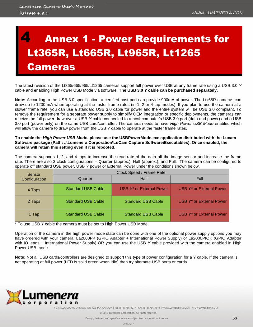
7 CAPELLA COURT, OTTAWA, ON K2E 8A7, CANADA | TEL (613) 736-4077 | FAX (613) 736-4071 | WWW.LUMENERA.COM | [email protected]
© 2017 Lumenera Corporation. All rights reserved.
Design, features, and specifications are subject to change without notice 51
09282017
WWW.LUMENERA.COM
Lumenera Camera User's Manual
Release 6.8.1
4 Annex 1 - Power Requirements for
Lt365R, Lt665R, Lt965R, Lt1265
Cameras
The latest revision of the Lt365/665/965/Lt1265 cameras support full power over USB at any frame rate using a USB 3.0 Y cable and enabling High Power USB Mode via software. The USB 3.0 Y cable can be purchased separately. Note: According to the USB 3.0 specification, a certified host port can provide 900mA of power. The Ltx65R cameras can draw up to 1200 mA when operating at the faster frame rates (in 1, 2 or 4 tap modes). If you plan to use the camera at a slower frame rate, you can use a standard USB 3.0 cable for power and the entire system will be USB 3.0 compliant. To remove the requirement for a separate power supply to simplify OEM integration or specific deployments, the cameras can receive the full power draw over a USB Y cable connected to a host computer’s USB 3.0 port (data and power) and a USB 3.0 port (power only) on the same USB card/controller. The camera needs to have High Power USB Mode enabled which will allow the camera to draw power from the USB Y cable to operate at the faster frame rates. To enable the High Power USB Mode, please use the USBPowerMode.exe application distributed with the Lucam Software package (Path: ..\Lumenera Corporation\LuCam Capture Software\Executables). Once enabled, the camera will retain this setting even if it is rebooted. The camera supports 1, 2, and 4 taps to increase the read rate of the data off the image sensor and increase the frame rate. There are also 3 clock configurations – Quarter (approx.), Half (approx.), and Full. The camera can be configured to operate off standard USB power, USB Y power or External Power under the conditions shown below.
Sensor Configuration
Clock Speed / Frame Rate
Quarter Half Full
4 Taps Standard USB Cable USB Y* or External Power USB Y* or External Power
2 Taps Standard USB Cable Standard USB Cable USB Y* or External Power
1 Tap Standard USB Cable Standard USB Cable USB Y* or External Power
* To use USB Y cable the camera must be set to High Power USB Mode. Operation of the camera in the high power mode state can be done with one of the optional power supply options you may have ordered with your camera: La2000PK (GPIO Adapter + International Power Supply) or La2000PIOK (GPIO Adapter with IO leads + International Power Supply) OR you can use the USB Y cable provided with the camera enabled in High Power USB mode. Note: Not all USB cards/controllers are designed to support this type of power configuration for a Y cable. If the camera is not operating at full power (LED is solid green when idle) then try alternate USB ports or cards.
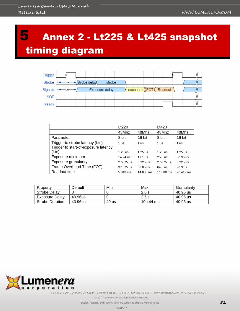
7 CAPELLA COURT, OTTAWA, ON K2E 8A7, CANADA | TEL (613) 736-4077 | FAX (613) 736-4071 | WWW.LUMENERA.COM | [email protected]
© 2017 Lumenera Corporation. All rights reserved.
Design, features, and specifications are subject to change without notice 52
09282017
WWW.LUMENERA.COM
Lumenera Camera User's Manual
Release 6.8.1
5 Annex 2 - Lt225 & Lt425 snapshot
timing diagram
Lt220 Lt420
48Mhz 40Mhz 48Mhz 40Mhz
Parameter 8 bit 16 bit 8 bit 16 bit
Trigger to strobe latency (Lts) 1 us 1 us 1 us 1 us
Trigger to start-of-exposure latency (Lte) 1.25 us 1.25 us 1.25 us 1.25 us
Exposure minimum 14.24 us 17.1 us 25.8 us 30.96 us
Exposure granularity 2.6875 us 3.225 us 2.6875 us 3.225 us
Frame Overhead Time (FOT) 37.625 us 58.05 us 64.5 us 90.3 us
Readout time 5.848 ms 14.035 ms 11.008 ms 26.419 ms
Property Default Min Max Granularity
Strobe Delay 0 0 2.6 s 40.96 us
Exposure Delay 40.96us 0 2.6 s 40.96 us
Strobe Duration 40.96us 40 us 10.444 ms 40.96 us
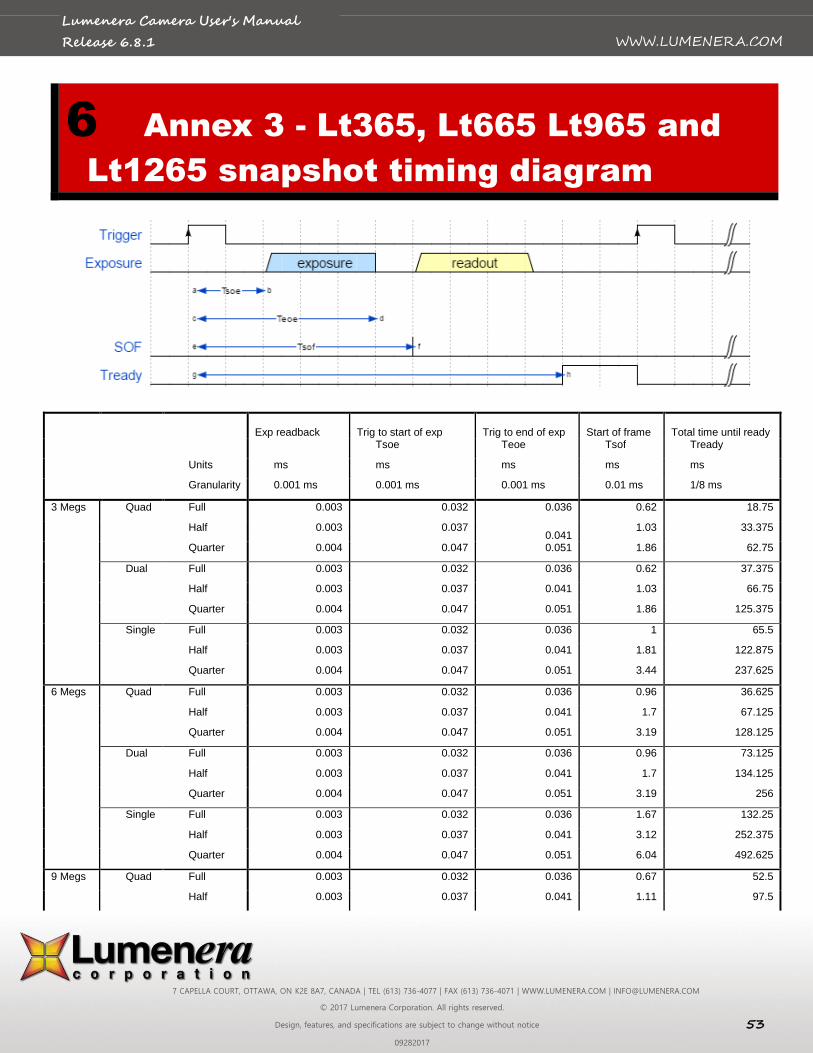
7 CAPELLA COURT, OTTAWA, ON K2E 8A7, CANADA | TEL (613) 736-4077 | FAX (613) 736-4071 | WWW.LUMENERA.COM | [email protected]
© 2017 Lumenera Corporation. All rights reserved.
Design, features, and specifications are subject to change without notice 53
09282017
WWW.LUMENERA.COM
Lumenera Camera User's Manual
Release 6.8.1
6 Annex 3 - Lt365, Lt665 Lt965 and
Lt1265 snapshot timing diagram
Exp readback Trig to start of exp Trig to end of exp Start of frame Total time until ready
Tsoe Teoe Tsof Tready
Units ms ms ms ms ms
Granularity 0.001 ms 0.001 ms 0.001 ms 0.01 ms 1/8 ms
3 Megs Quad Full 0.003 0.032 0.036 0.62 18.75
Half 0.003 0.037 0.041
1.03 33.375
Quarter 0.004 0.047 0.051 1.86 62.75
Dual Full 0.003 0.032 0.036 0.62 37.375
Half 0.003 0.037 0.041 1.03 66.75
Quarter 0.004 0.047 0.051 1.86 125.375
Single Full 0.003 0.032 0.036 1 65.5
Half 0.003 0.037 0.041 1.81 122.875
Quarter 0.004 0.047 0.051 3.44 237.625
6 Megs Quad Full 0.003 0.032 0.036 0.96 36.625
Half 0.003 0.037 0.041 1.7 67.125
Quarter 0.004 0.047 0.051 3.19 128.125
Dual Full 0.003 0.032 0.036 0.96 73.125
Half 0.003 0.037 0.041 1.7 134.125
Quarter 0.004 0.047 0.051 3.19 256
Single Full 0.003 0.032 0.036 1.67 132.25
Half 0.003 0.037 0.041 3.12 252.375
Quarter 0.004 0.047 0.051 6.04 492.625
9 Megs Quad Full 0.003 0.032 0.036 0.67 52.5
Half 0.003 0.037 0.041 1.11 97.5
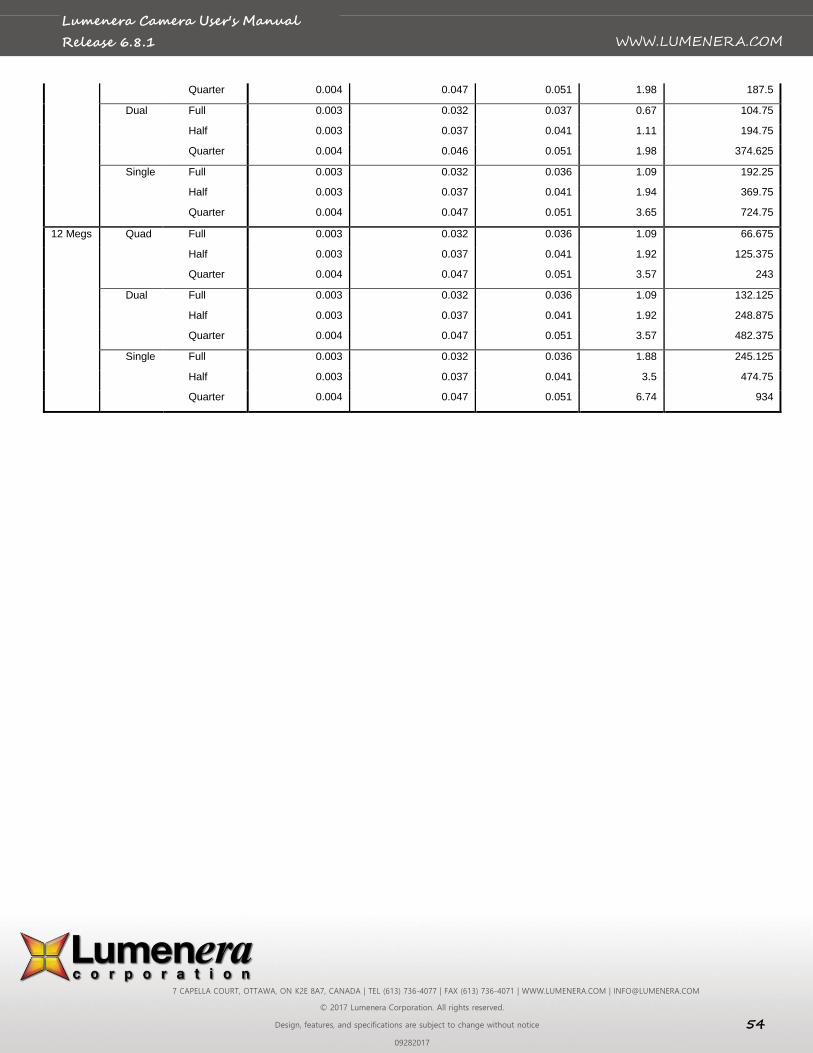
7 CAPELLA COURT, OTTAWA, ON K2E 8A7, CANADA | TEL (613) 736-4077 | FAX (613) 736-4071 | WWW.LUMENERA.COM | [email protected]
© 2017 Lumenera Corporation. All rights reserved.
Design, features, and specifications are subject to change without notice 54
09282017
WWW.LUMENERA.COM
Lumenera Camera User's Manual
Release 6.8.1
Quarter 0.004 0.047 0.051 1.98 187.5
Dual Full 0.003 0.032 0.037 0.67 104.75
Half 0.003 0.037 0.041 1.11 194.75
Quarter 0.004 0.046 0.051 1.98 374.625
Single Full 0.003 0.032 0.036 1.09 192.25
Half 0.003 0.037 0.041 1.94 369.75
Quarter 0.004 0.047 0.051 3.65 724.75
12 Megs Quad Full 0.003 0.032 0.036 1.09 66.675
Half 0.003 0.037 0.041 1.92 125.375
Quarter 0.004 0.047 0.051 3.57 243
Dual Full 0.003 0.032 0.036 1.09 132.125
Half 0.003 0.037 0.041 1.92 248.875
Quarter 0.004 0.047 0.051 3.57 482.375
Single Full 0.003 0.032 0.036 1.88 245.125
Half 0.003 0.037 0.041 3.5 474.75
Quarter 0.004 0.047 0.051 6.74 934
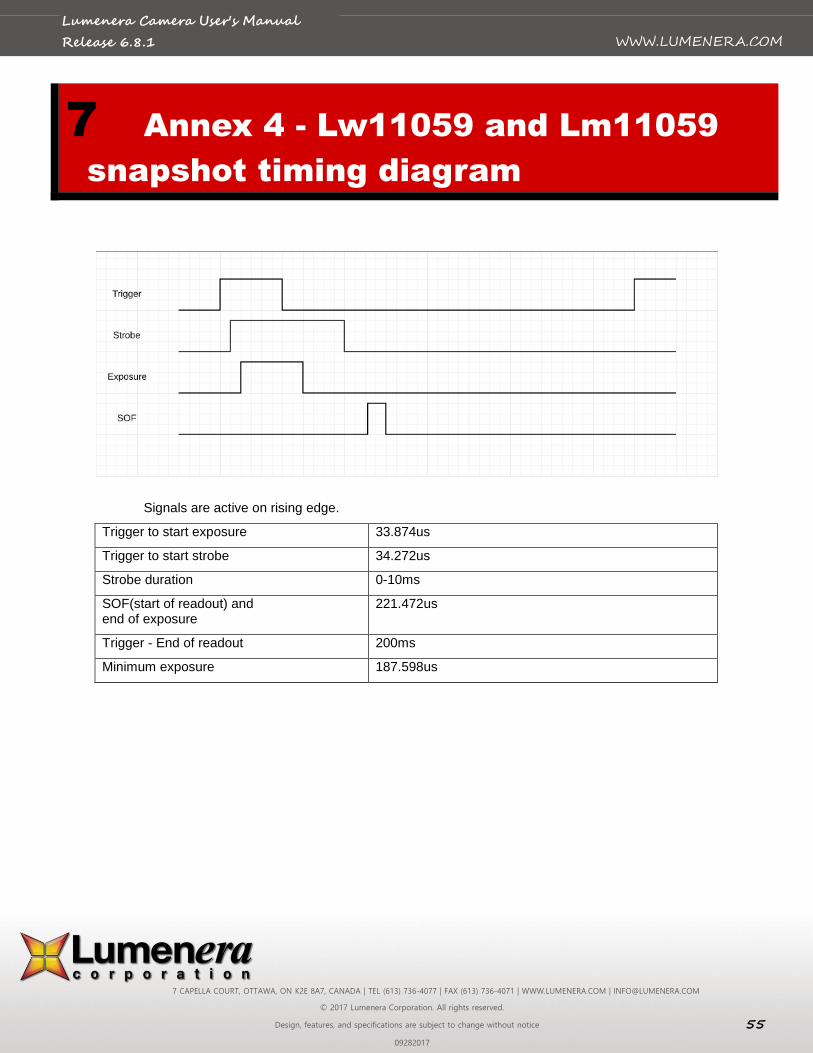
7 CAPELLA COURT, OTTAWA, ON K2E 8A7, CANADA | TEL (613) 736-4077 | FAX (613) 736-4071 | WWW.LUMENERA.COM | [email protected]
© 2017 Lumenera Corporation. All rights reserved.
Design, features, and specifications are subject to change without notice 55
09282017
WWW.LUMENERA.COM
Lumenera Camera User's Manual
Release 6.8.1
7 Annex 4 - Lw11059 and Lm11059
snapshot timing diagram
Signals are active on rising edge.
Trigger to start exposure 33.874us
Trigger to start strobe 34.272us
Strobe duration 0-10ms
SOF(start of readout) and end of exposure
221.472us
Trigger - End of readout 200ms
Minimum exposure 187.598us
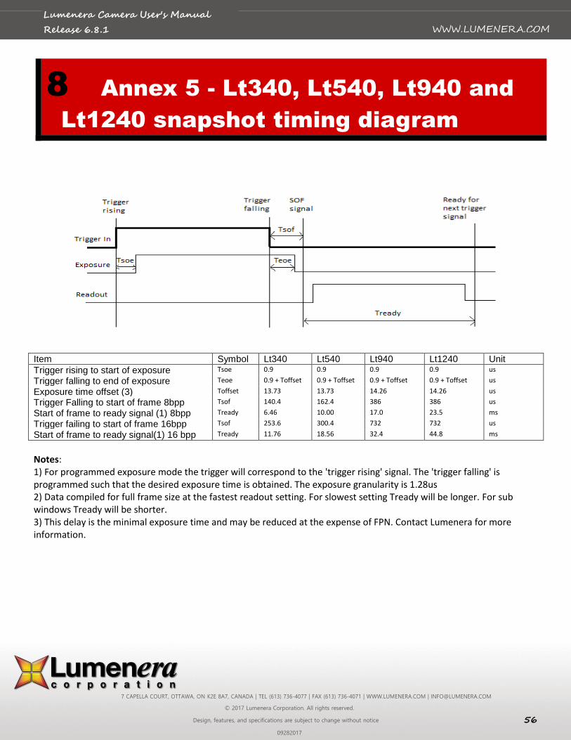
7 CAPELLA COURT, OTTAWA, ON K2E 8A7, CANADA | TEL (613) 736-4077 | FAX (613) 736-4071 | WWW.LUMENERA.COM | [email protected]
© 2017 Lumenera Corporation. All rights reserved.
Design, features, and specifications are subject to change without notice 56
09282017
WWW.LUMENERA.COM
Lumenera Camera User's Manual
Release 6.8.1
8 Annex 5 - Lt340, Lt540, Lt940 and
Lt1240 snapshot timing diagram
Item Symbol Lt340 Lt540 Lt940 Lt1240 Unit
Trigger rising to start of exposure Tsoe 0.9 0.9 0.9 0.9 us
Trigger falling to end of exposure Teoe 0.9 + Toffset 0.9 + Toffset 0.9 + Toffset 0.9 + Toffset us
Exposure time offset (3) Toffset 13.73 13.73 14.26 14.26 us
Trigger Falling to start of frame 8bpp Tsof 140.4 162.4 386 386 us
Start of frame to ready signal (1) 8bpp Tready 6.46 10.00 17.0 23.5 ms
Trigger failing to start of frame 16bpp Tsof 253.6 300.4 732 732 us
Start of frame to ready signal(1) 16 bpp Tready 11.76 18.56 32.4 44.8 ms
Notes: 1) For programmed exposure mode the trigger will correspond to the 'trigger rising' signal. The 'trigger falling' is programmed such that the desired exposure time is obtained. The exposure granularity is 1.28us 2) Data compiled for full frame size at the fastest readout setting. For slowest setting Tready will be longer. For sub windows Tready will be shorter. 3) This delay is the minimal exposure time and may be reduced at the expense of FPN. Contact Lumenera for more information.