Embed Size (px)
Citation preview
1
1
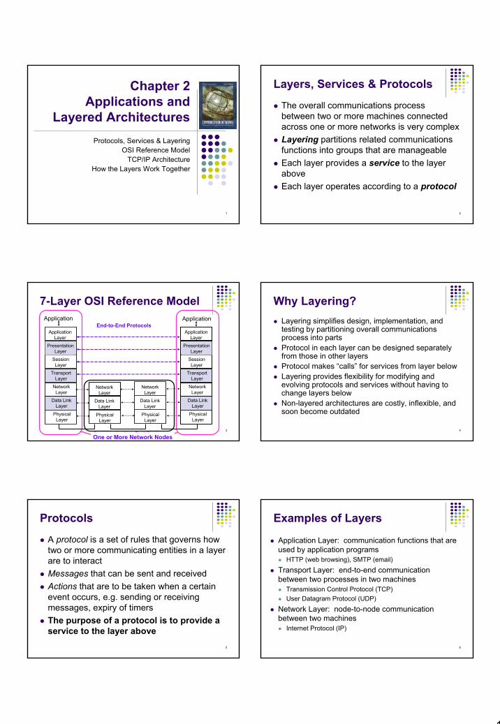
Chapter 2 Applications and
Layered ArchitecturesProtocols, Services & Layering
OSI Reference ModelTCP/IP Architecture
How the Layers Work Together
2
Layers, Services & Protocols
The overall communications process between two or more machines connected across one or more networks is very complexLayering partitions related communications functions into groups that are manageableEach layer provides a service to the layer aboveEach layer operates according to a protocol
3
7-Layer OSI Reference Model
ApplicationLayer
PresentationLayer
SessionLayer
TransportLayer
NetworkLayer
Data LinkLayer
PhysicalLayer
ApplicationLayer
PresentationLayer
SessionLayer
TransportLayer
NetworkLayer
Data LinkLayer
PhysicalLayer
NetworkLayer
Application Application
Data LinkLayer
PhysicalLayer
NetworkLayer
Data LinkLayer
PhysicalLayer
Communicating End SystemsOne or More Network Nodes
End-to-End Protocols
4
Why Layering?Layering simplifies design, implementation, and testing by partitioning overall communications process into partsProtocol in each layer can be designed separately from those in other layersProtocol makes “calls” for services from layer belowLayering provides flexibility for modifying and evolving protocols and services without having to change layers belowNon-layered architectures are costly, inflexible, and soon become outdated
5
Protocols
A protocol is a set of rules that governs how two or more communicating entities in a layer are to interactMessages that can be sent and receivedActions that are to be taken when a certain event occurs, e.g. sending or receiving messages, expiry of timersThe purpose of a protocol is to provide a service to the layer above
6
Examples of Layers
Application Layer: communication functions that are used by application programs
HTTP (web browsing), SMTP (email)
Transport Layer: end-to-end communication between two processes in two machines
Transmission Control Protocol (TCP) User Datagram Protocol (UDP)
Network Layer: node-to-node communication between two machines
Internet Protocol (IP)

2
7
Example: HTTP
HTTP is an application layer protocolRetrieves documents on behalf of a browser application programHTTP specifies fields in request messages and response messages
Request types; Response codesContent type, options, cookies, …
HTTP specifies actions to be taken upon receipt of certain messages
8
HTTPClient
HTTP Protocol
GET
Response
HTTPServer
HTTP assumes messages can be exchanged directly between HTTP client and HTTP serverIn fact, HTTP client and server are processes running in two different machines across the InternetHTTP uses the reliable stream transfer service provided by TCP
9
Example: TCPTCP is a transport layer protocolProvides reliable byte stream service between two processes in two computers across the InternetSequence numbers keep track of the bytes that have been transmitted and receivedError detection and retransmission used to recover from transmission errors and lossesTCP is connection-oriented: the sender and receiver must first establish an association and set initial sequence numbers before data is transferredConnection ID is specified uniquely by
(send port #, send IP address, receive port #, receiver IP address)10
HTTPserver
HTTPclient
TCP
Port 80Port 1127
HTTP uses service of TCP
TCP
ResponseGET
TCP80, 1127 GET 1127, 80 bytesResponseGETResponse
11
SummaryLayers: related communications functions
Application Layer: HTTP, DNSTransport Layer: TCP, UDPNetwork Layer: IP
Services: a protocol provides a communication service to the layer above
TCP provides connection-oriented reliable byte transfer serviceUDP provides best-effort datagram service
Each layer builds on services of lower layersHTTP builds on TCPDNS builds on top UDPTCP and UDP build on IP
12
Chapter 2Applications and
Layered Architectures
OSI Reference Model
3
13
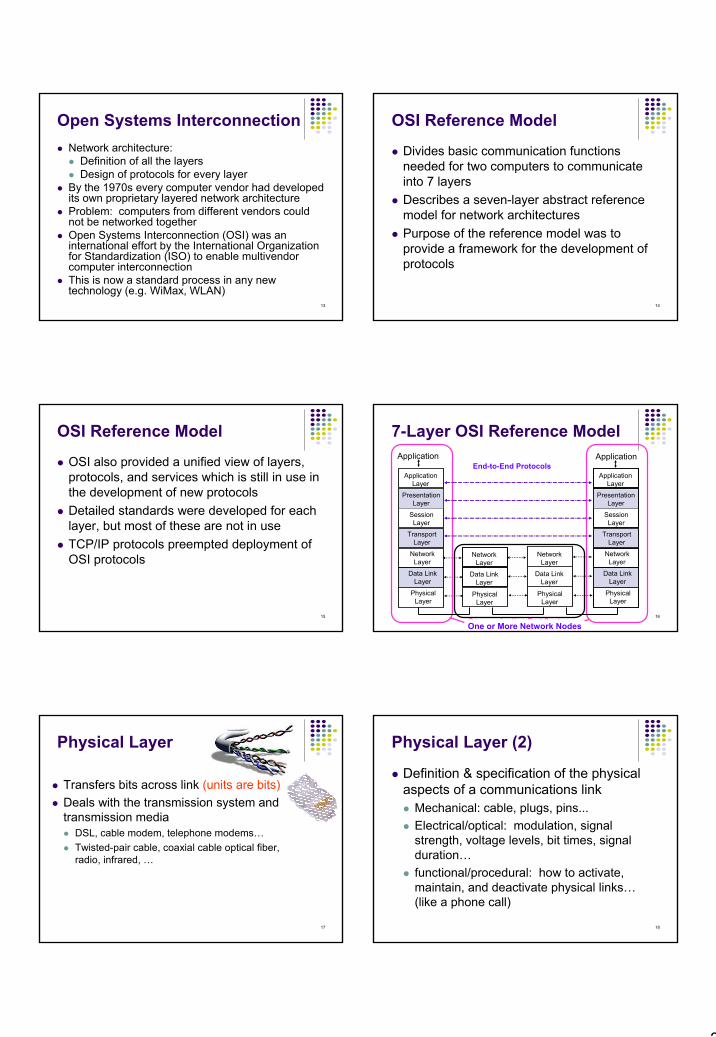
Open Systems InterconnectionNetwork architecture:
Definition of all the layers Design of protocols for every layer
By the 1970s every computer vendor had developed its own proprietary layered network architectureProblem: computers from different vendors could not be networked togetherOpen Systems Interconnection (OSI) was an international effort by the International Organization for Standardization (ISO) to enable multivendorcomputer interconnectionThis is now a standard process in any new technology (e.g. WiMax, WLAN)
14
OSI Reference Model
Divides basic communication functions needed for two computers to communicate into 7 layersDescribes a seven-layer abstract reference model for network architecturesPurpose of the reference model was to provide a framework for the development of protocols
15
OSI Reference Model
OSI also provided a unified view of layers, protocols, and services which is still in use in the development of new protocolsDetailed standards were developed for each layer, but most of these are not in useTCP/IP protocols preempted deployment of OSI protocols
16
7-Layer OSI Reference Model
ApplicationLayer
PresentationLayer
SessionLayer
TransportLayer
NetworkLayer
Data LinkLayer
PhysicalLayer
ApplicationLayer
PresentationLayer
SessionLayer
TransportLayer
NetworkLayer
Data LinkLayer
PhysicalLayer
NetworkLayer
Application Application
Data LinkLayer
PhysicalLayer
NetworkLayer
Data LinkLayer
PhysicalLayer
Communicating End SystemsOne or More Network Nodes
End-to-End Protocols
17
Physical Layer
Transfers bits across link (units are bits)Deals with the transmission system and transmission media
DSL, cable modem, telephone modems…Twisted-pair cable, coaxial cable optical fiber, radio, infrared, …
18
Physical Layer (2)
Definition & specification of the physical aspects of a communications link
Mechanical: cable, plugs, pins...Electrical/optical: modulation, signal strength, voltage levels, bit times, signal duration…functional/procedural: how to activate, maintain, and deactivate physical links…(like a phone call)

4
19
Data Link LayerTransfers frames (blocks of info) across directconnectionsGroups bits into frames; adds check bitsDetection of bit errors; Retransmission of framesActivation, maintenance, & deactivation of data link connections
Data LinkLayer
PhysicalLayer
Data LinkLayer
PhysicalLayer
frames
bits
20
Data Link LayerLink includes case where multiple users need to be connected to the medium (example?)Medium access control for local area networksFlow control (so as not to overwhelm buffer on other end)
21
Network Layer
Transfers packets across multiple links and/or multiple networks (no pt-2-pt any more)Addressing must scale to large networksNodes jointly execute routing algorithm to determine paths across the network (makes net. layer most complex)
22
Network Layer (2)
Routing: procedure to select path across netWhen two machines are connected through
Same PS net: single address sp and routing procedureDifferent nets:
nets differ in internal routing/addressing/packet sizeNeed an internetwork protocol
23
Network Layer (3)
Forwarding transfers packet across a nodeCongestion control to deal with traffic surgesConnection setup, maintenance, and teardown when connection-based
24
ApplicationLayer
PresentationLayer
SessionLayer
TransportLayer
NetworkLayer
Data LinkLayer
PhysicalLayer
ApplicationLayer
PresentationLayer
SessionLayer
TransportLayer
NetworkLayer
Data LinkLayer
PhysicalLayer
NetworkLayer
Application Application
Data LinkLayer
PhysicalLayer
NetworkLayer
Data LinkLayer
PhysicalLayer
Communicating End SystemsOne or More Network Nodes
End-to-End Protocols
5
25
Each node must implement lower 3 layersLower 2 layers involve interaction of peer-2-peer processes across a single linkNet. Layer in source and destination are not peers (don’t talk directly)Nodes in Net. Layer jointly execute routingTop 4 layers involve interaction of peer processes across net.
26
Transport Layer
Transfers data end-to-end from process in a machine to process in another machine:
Reliable stream transfer: error free transfer of a seq. of bytes or messages or quick-and-simple (unreliable) single-block transfer (just provide appropriate address)
TransportLayer
NetworkLayer
TransportLayer
NetworkLayer
NetworkLayer
NetworkLayer
Communication Network
27
Multiplexing: for opt. net service, multiplex several trans. layer connections into a single net. layer connectionMultiplexing enabled by port numbers Splitting: for high throughput, layer can use splitting to support connection over several net layer connectionMessage segmentation and reassemblyConnection setup, maintenance, and release
28
Application & Upper LayersApplication Layer: Provides services that are frequently required by applications, like: web access, file transfer, email…Presentation Layer: machine-independent representation of data…(different machines use different ways to represent integers and no.)Session Layer: dialog management (how data is exchanged, e.g. half or full duplex)
ApplicationLayer
PresentationLayer
SessionLayer
TransportLayer
Application
ApplicationLayer
TransportLayer
Application
Incorporated into Application Layer
29
OSI wanted to develop a layering model standards for computer nets (protocols use)By time protocols were developed, TCP/IP emerged as an alternative (time to market)
30
Headers & TrailersEach protocol uses a header carrying control information: address, sequence number, flags, size indicators, etc…Check bits may be appended (trailer) for error detection
ApplicationLayer
TransportLayer
NetworkLayer
Data LinkLayer
PhysicalLayer
ApplicationLayer
TransportLayer
NetworkLayer
Data LinkLayer
PhysicalLayer
Application ApplicationAPP DATA
AH APP DATA
TH AH APP DATA
NH TH AH APP DATA
DH NH TH AH APP DATA CRC
bits

6
31
At destination, 1. each layer reads header and trailer info to
determine action to be taken2. Strips header and trailer3. Passes forward to higher layer
32
OSI Unified View: ProtocolsThe entities comprising the corresponding layers on different machines are called peer processes.A process on one machine interacts with a process on another machine across a peer interface (HTTP on client and server are peer processes)Layer-n peer processes communicate by exchanging Protocol Data Units (PDUs) (bits, frames, packets, segments)
nEntity
nEntity
Layer n peer protocol
n-PDUs
33
OSI Unified View: Protocols
Each PDU contains a header and possibly a trailerLayer n in one machine interacts with layer n in another machine to provide a service to layer n +1The machines use a set of rules and conventions called the layer-n protocol.
nEntity
nEntity
Layer n peer protocol
n-PDUs
34
OSI Unified View: ServicesCommunication between peer processes is virtual and actually indirectLayer n+1 transfers information by invoking the services provided by layer n
Layer n serves layer n+1Layer n+1 is a user of service provided by layer n
Pass info from layer n+1 to layer n through a software port called Service Access Points (SAP’s) Layer n+1 is only interested in correct execution to transfer its PDU to the peer process (how execution is done is irrelevant)
35
OSI Unified View: Services (2)Each layer passes data & control information to the layer below it until the physical layer is reached and transfer occursThe data passed to the layer below is called a Service Data Unit (SDU)SDU’s are encapsulated in PDU’s + control info (i.e. what to do with data)
36
n+1entity
n-SAP
n+1entity
n-SAP
n entity n entity
n-SDUn-SDU
n-SDUH
H n-SDU
n-PDU
Layers, Services & Protocols
Service Interface
7
37
Connectionless & Connection-Oriented Services
Connection-OrientedThree-phases:
1. Connection setup between two SAPsto initialize state information
2. SDU transfer3. Connection releaseE.g. TCP, ATM
(like a phone call)
ConnectionlessImmediate SDU transfer (control info contains address of destination)No connection setupE.g. UDP, IP
Layered services not always of same type
TCP operates over IP IP operates over ATM
(like TV broadcast)38
n-PDU
Segmentation & ReassemblyA layer may impose a limit on the size of a data block that it can transfer for implementation or other reasonsThus a layer-n SDU may be too large to be handled as a single unit by layer-(n-1)Sender side: SDU is segmented into multiple PDUsReceiver side: SDU is reassembled from sequence of PDUs
n-SDU
n-PDU n-PDU n-PDU
Segmentation(a)
n-SDU
n-PDU n-PDU
Reassembly(b)
39
n+1entity
n+1entity
n+1entity
n+1entity
MultiplexingSharing of layer n service by multiple layer n+1 usersMultiplexing tag or ID required in each PDU to determine which users an SDU belongs toSplitting is the opposite process
n entity n entity
n-SDUn-SDU
n-SDUH
H n-SDU
n-PDU40
SummaryLayers: related communications functions
Application Layer: HTTP, DNSTransport Layer: TCP, UDPNetwork Layer: IP
Services: a protocol provides a communications service to the layer above
TCP provides connection-oriented reliable byte transfer serviceUDP provides best-effort datagram service
Each layer builds on services of lower layersHTTP builds on top of TCPDNS builds on top of UDPTCP and UDP build on top of IP
41
Chapter 2Applications and
Layered Architectures
Example: TCP/IP ArchitectureWidely Used Networking Technology
42
Section 2.3, TCP/IP
TCP/IP net Architecture: set of protocols that allows comm. across multiple diverse netsDeveloped by the US Defense Advanced Research Project Agency (DARPA) for its packet switched network (ARPANET)Emphasis on robustness and flexibility Eventually led to Internet which connects world computers

8
43
Internet: InternetworkingInternetworking is part of network layer and provides transfer of packets across multiple possibly dissimilar networksGateways (routers) direct packets across networks
G = gateway H = host
Net 1
Net 5
Net 3
Net 2
HNet 3
G
H
H
H
GG
GG
G
Net 1
Net 2 Net 4Net 5
Ethernet LAN
ATMSwitch
ATMSwitch
ATMSwitch
ATMSwitch
ATMNetwork
44
Why Internetworking?To build a “network of networks” or Internet
operating over multiple (different) network technologiesproviding worldwide connectivity through IP packet transfer independent of underlying network technologiesproviding common interface to user applications
G
GG
GG
G
H
Net 5Net 5
H Net 5Net 2
H
Net 5Net 3H
Net 5Net 1
Net 5Net 4
45
TCP/IP TCP/IP Architecture consists of 4 layersTCP/IP application layer incorporates the functions of the top 3 OSI layersApplication layer runs directly over transport layer
Network Access Layer
46
Application Layer
Support for user applicationse.g.,
HTTP - Hypertext Transfer Protocol SMTP - Simple Mail Transfer Protocol FTP - File Transfer Protocol DNS - Domain Name SystemSNMP - Simple Network Management ProtocolTelnet…
47
Transport Layer
Responsible for providing the Application layer with session and datagram communication services
Core protocolsTransport Control Protocol (TCP)User Datagram Protocol (UDP)
48
Transport LayerTCP:
One-to-one, connection-oriented serviceReliable delivery of data
SequencingAcknowledgement of packets sentRetransmission of lost packets
UDP:One-to-one or one-to-many, connectionlessUnreliable - not guaranteed deliveryNo preservation of sequenceNo protection against duplicationMinimum overhead

9
49
Internet LayerProvides a best-effort connectionless packet transferAdvantage: Robust to failures in parts of the networkSystems may be attached to different networksAddressing, packaging, and routingImplemented in end systems and routersCore protocols
Internet Protocol (IP)Address Resolution Protocol (ARP) Internet Control Message Protocol (ICMP) Internet Group Management Protocol (IGMP)
50
Internet Protocol ApproachIP packets transfer information across InternetHost A IP → router→ router…→ router→ Host B IPIP layer in each router determines next hop (router)Network interfaces transfer IP packets across networks
Router
InternetLayer
NetworkInterface
TransportLayer
InternetLayer
NetworkInterface
TransportLayer
InternetLayer
NetworkInterface
Host A Host B
Net 5Net 1
Net 5Net 2 Net 5Net 3
Router
InternetLayer
NetworkInterface
Router
InternetLayer
NetworkInterface
Net 5Net 4
51
Internet Protocol ApproachInternet layer corresponds to the net. Layer in OSIKey requirement is globally unique address for machines attached to internetIP packets exchanged between routers without connection setupPackets routed independently (so possibility for different paths); no connection set up
52
Internet Protocol Approach
Connectionless approach makes system robust
if failure occurs, packets routed around failure points; no need to setup connections again
Gateways can discard packetsResponsibility of recovering losses passed to transport layer
53
Network Interface LayerDeals with network specific aspects for transfer of packetsVarious networks implies the need for various interfaces (ATM, Ethernet, Token ring… )Protocols that access intermediate networks: encapsulates packet IP packet into packet or frame of underlying networkNetwork interface is technology dependentInternet layer is technology independent (transparent to underlying network, i.e. does not depend on details of underlying networks)
54
Network Interface LayerPhysical interface
Physical interface between data transmission device (e.g. computer) and transmission medium or networkCharacteristics of transmission mediumSignal levelsData rates
Network interfaceMedium Access Control.Exchange of data between end system and networkDestination address provisionInvoking services like priority

10
55
TCP/IP Protocol Suite
Access thru IP ALWAYS
Diverse network technologies
Reliable stream service
Userdatagram service
Distributed applications
HTTP SMTP RTP
TCP UDP
IP
Network
interface 1
Network
interface 3Network
interface 2
DNS
Best-effort connectionless packet transfer
56
Some Protocols in TCP/IP Suite
DNS
57
TCP/IP
Why TCP/IP is so powerful?Single IP protocol over various nets provides indep. from underlying technologies Communication services of TCP and UDP provide network indep. platform on which applications can be developed.So multiple technologies can co-exist
58
CH. 8; IP and Physical AddressesPhysical Address:
Identifies the host on the network interfaceEach network interface card has a unique address called medium access control (MAC) or physical addressUsed to deliver frames over the same network (LAN)
IP Address:Globally unique addressComposed of two parts: Network and HostEach network (LAN) has a different IP addressHosts within a LAN have IP addresses with the same Network part and different Host parts
59
HTTP Request
TCP Header
Header contains source and destination port numbers
Header contains source and destination IP addresses; transport protocol type
IP Header
Header contains source and destination physical addresses; network protocol type
Frame Check Sequence
Ethernet Header
60
Each host is identified by a globally unique IP addressIP packets routed according to Net IDRouters compute routing tables using distributed algorithmRouter: a node connected to 2 or more physical networks; with each net interface assigned to unique IP address. Thus, a router can have more than one IP address.
11
61
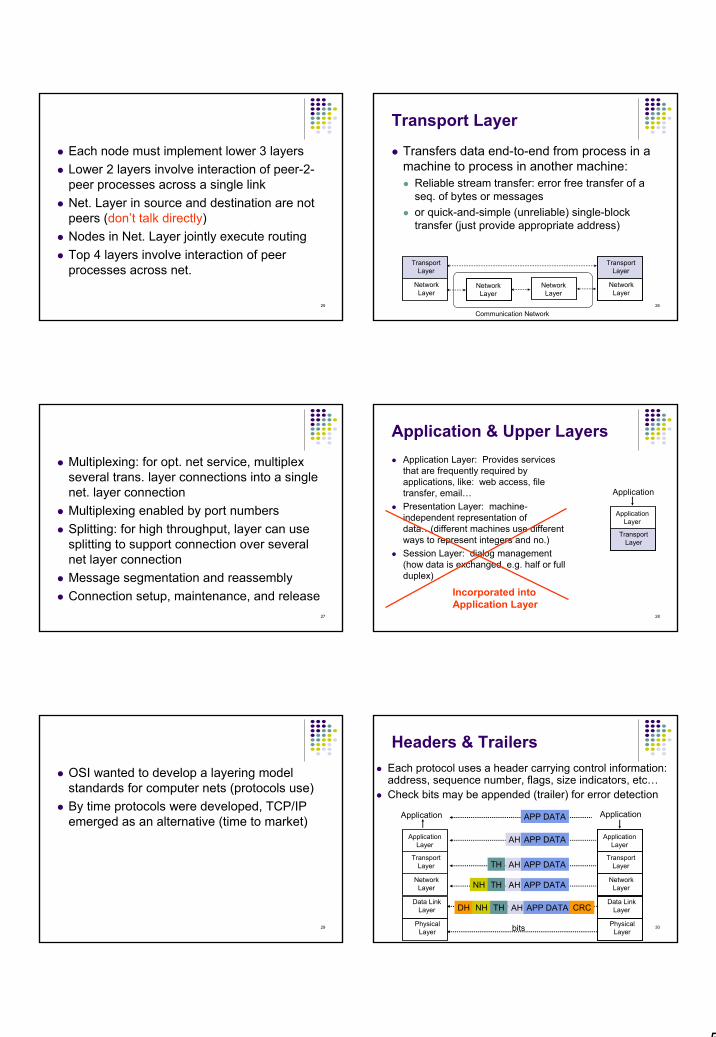
Names and IP AddressesRouting is done based on 32-bit IP addressesDotted-decimal notation
Example; 32-Bit IP: 10000000 10000111 01000100 00000101
128.100.11.1 (Dotted-decimal notation) Hosts are also identified by name
Easier to rememberHierarchical name structuretesla.comm.utoronto.edu
Domain Name System (DNS) provides conversion between names and addresses
62
0 Net ID Host ID
Net ID Host ID1 0
Net ID Host ID1 1 0
1 1 1 0 Multicast address
1 1 1 1 Reserved for experiments
Class A
Class B
Class C
Class D
Class E
0 1 2 3 8 16 31Bit position:
Classes of IP Addresses
63
IPv4 Addressing
64
Reserved IP Addresses
Certain host addresses are reserved and cannot be assigned to devices on a network.
An IP address that has binary 0s in all host bit positions is reserved for the network address.
An IP address that has binary 1s in all host bit positions is reserved as the broadcast address.
65
Broadcast AddressA broadcast address is an address that has all 1s in the host field. The network number designates the segment, and the rest of the address tells every IP host in that network that this is a broadcast message, and that the device needs to pay attention to the message. All devices on a network recognize their own host IP address as well as the broadcast address for their network.For example:
139.219.0.0 Class B Network Address139.219.55.16 Class B Host Address139.219.255.255 Class B broadcast address
66
Public and Private IP Addresses No two machines that connect to a public network can have the same IP address because public IP addresses are global and standardized. However, private networks that are not connected to the Internetmay use any host addresses, as long as each host within the private network is unique. RFC 1918 sets aside three blocks of IP addresses for private, internal use. Connecting a network using private addresses to the Internet requires translation of the private addresses to public addresses using Network Address Translation (NAT).
12
67
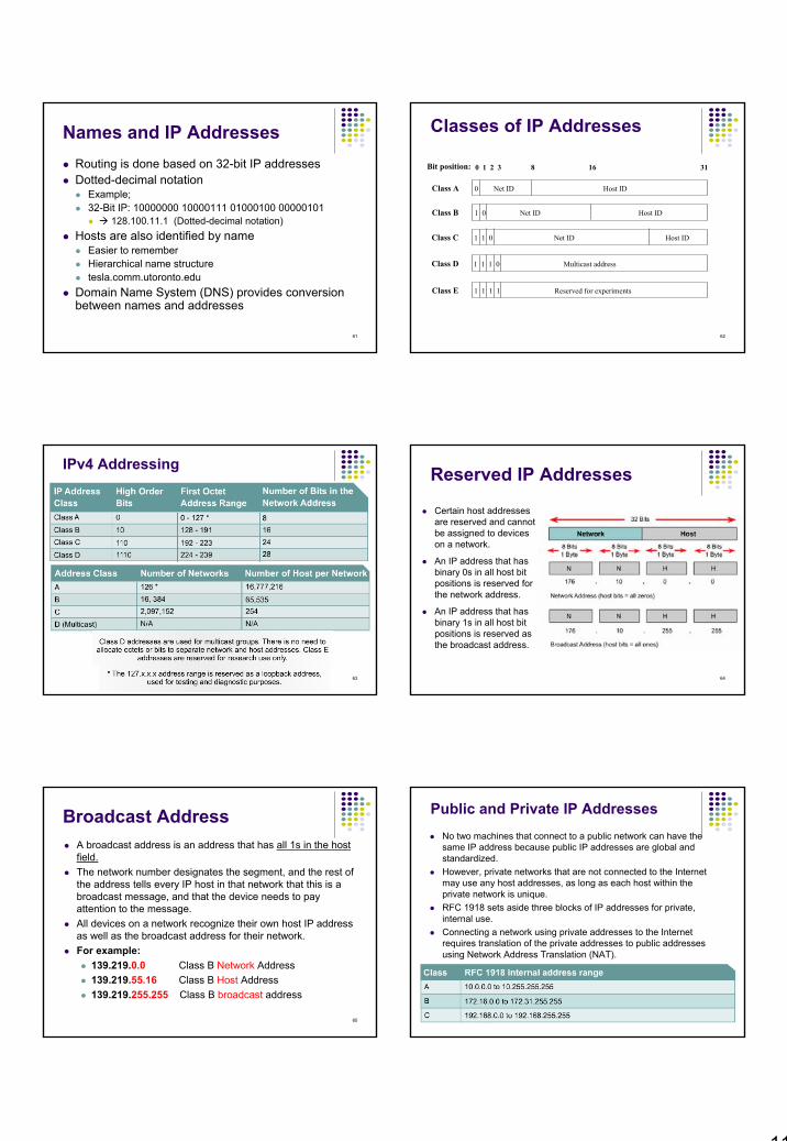
Physical AddressesLANs assign physical address to the equipment attached to the network Format of physical address depends on particular type of network usedExample: Ethernet uses 48-bit addresses
Each Ethernet network interface card (NIC) has globally unique Medium Access Control (MAC) or physical addressFirst 24 bits identify NIC manufacturer; second 24 bits are serial number This guarantees a unique phys address to each machine in the LAN net 00:90:27:96:68:07 12 hex numbers
Intel 68
The network uses its own logical address to transfer packets or frames to the appropriate destinationIP address needs to be matched to physical address at each IP network interface (e.g., using Address Resolution Protocol, (ARP))
69
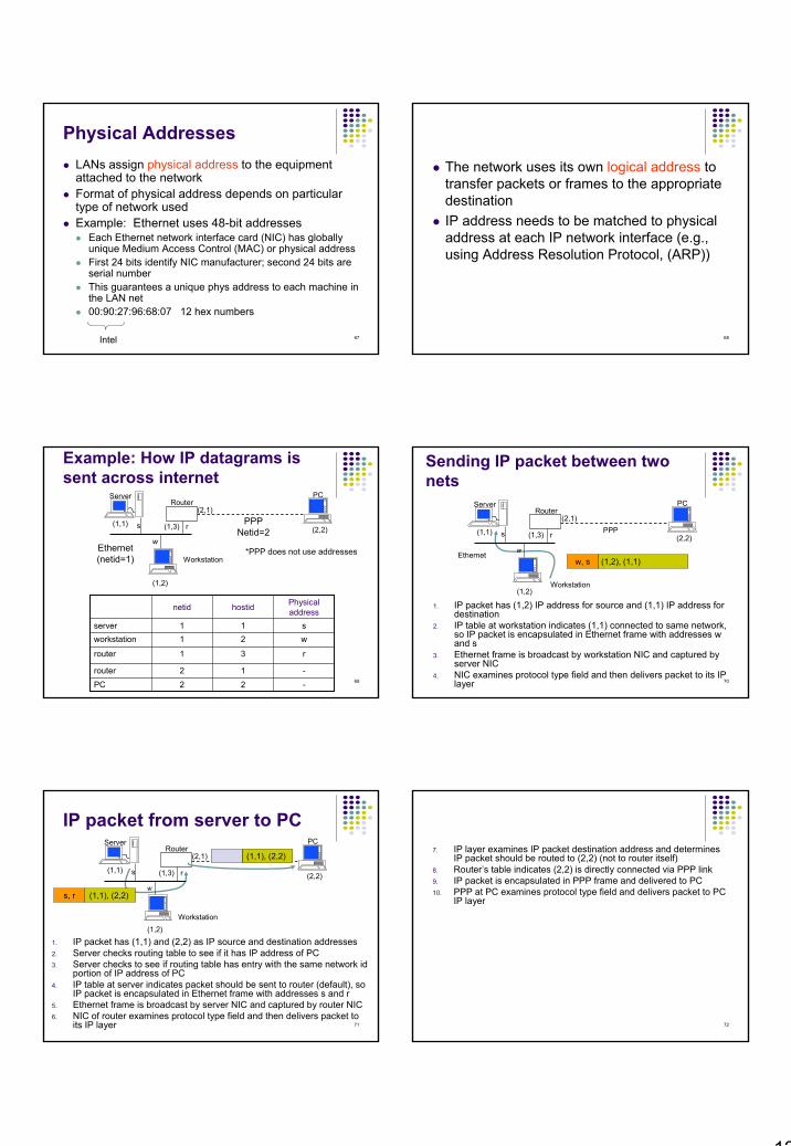
Example: How IP datagrams is sent across internet
(1,1) s
(1,2)
w
(2,1)
(1,3) r (2,2)PPP
Netid=2Ethernet(netid=1)
PCServerRouter
Workstation
-12router
-22PC
Physical addresshostidnetid
r31router
w21workstations11server
*PPP does not use addresses
70
Sending IP packet between two nets
1. IP packet has (1,2) IP address for source and (1,1) IP address for destination
2. IP table at workstation indicates (1,1) connected to same network, so IP packet is encapsulated in Ethernet frame with addresses w and s
3. Ethernet frame is broadcast by workstation NIC and captured by server NIC
4. NIC examines protocol type field and then delivers packet to its IP layer
(1,1) s
(1,2)
w
(2,1)
(1,3) r (2,2)PPP
Ethernet
PCServerRouter
Workstation
(1,2), (1,1) w, s
71
IP packet from server to PC
(1,1) s
(1,2)
w
(2,1)
(1,3) r (2,2)
PCServerRouter
Workstation
1. IP packet has (1,1) and (2,2) as IP source and destination addresses2. Server checks routing table to see if it has IP address of PC3. Server checks to see if routing table has entry with the same network id
portion of IP address of PC4. IP table at server indicates packet should be sent to router (default), so
IP packet is encapsulated in Ethernet frame with addresses s and r5. Ethernet frame is broadcast by server NIC and captured by router NIC6. NIC of router examines protocol type field and then delivers packet to
its IP layer
(1,1), (2,2) s, r
(1,1), (2,2)
72
7. IP layer examines IP packet destination address and determines IP packet should be routed to (2,2) (not to router itself)
8. Router’s table indicates (2,2) is directly connected via PPP link9. IP packet is encapsulated in PPP frame and delivered to PC10. PPP at PC examines protocol type field and delivers packet to PC
IP layer

13
73
Originaladdress
Subnettedaddress
Net ID Host ID1 0
Net ID Host ID1 0 Subnet ID
Ch8; Introduction to Subnetting
74
Reasons for SubnettingReduces the size of a broadcast domain.Provides addressing flexibility for the network administrator.
Each LAN must have its own network or subnetwork address.Provides broadcast containment and low-level security on the LAN. Provides some security since access to other subnets is only available through the services of a router.
75
Subnet: Conceptual View
Network Mask: 11111111 11111111 1111 0000 00000000255 . 255 . 240 . 0
Binary 1’s: subnet and network bits
Create another section in the IP Address called Subnet by borrowing bits from the host fields in the subnet mask.
76
Borrowing Bits
3 bits borrowed allows 23-2 or 6 subnets
The available bits for assignment to the subnet field in a Class A address is 22 bits while a Class B address has 14 bits.
77
Subnetting Class A and B Networks
5 bits borrowed allows 25-2 or 30 subnets
12 bits borrowed allows 212-2 or 4094 subnets78
Performing the “AND” Operation to Find the Subnet Address