Embed Size (px)
Citation preview

TABLE OF CONTENTS_____________________________________________________________________________
7. OPTIONAL EQ.
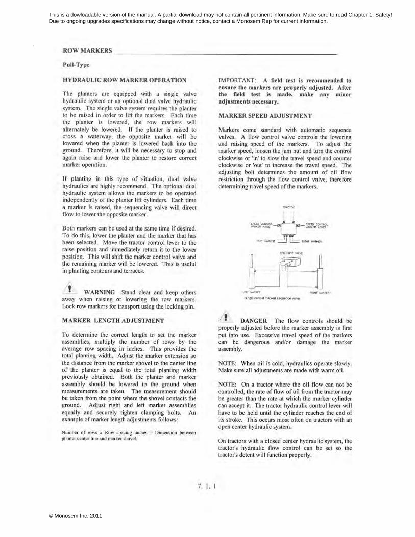
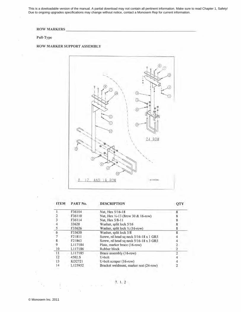
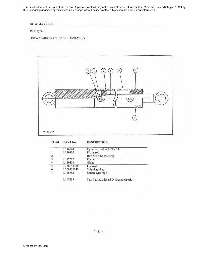
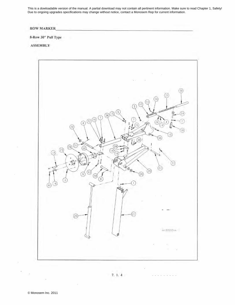
7. 1. TRIPLE FOLD ROW MARKERS
7. 4. MICROSEM INSECTICIDE, Twin-Row
SYNC-ROW® system for Twin-Row
7. 5. DRY FERTILIZER, Pull-Type
7. 7. LIQUID FERTILIZER, Pull-Type
CSS- CENTRAL SEED SYSTEM, Twin-Row
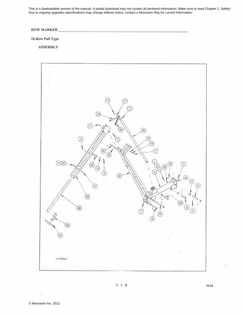
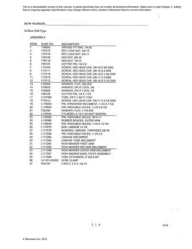
This is a dowloadable version of the manual. A partial download may not contain all pertinent information. Make sure to read Chapter 1, Safety! Due to ongoing upgrades specifications may change without notice, contact a Monosem Rep for current information.
© Monosem Inc. 2011
This is a dowloadable version of the manual. A partial download may not contain all pertinent information. Make sure to read Chapter 1, Safety! Due to ongoing upgrades specifications may change without notice, contact a Monosem Rep for current information.
© Monosem Inc. 2011
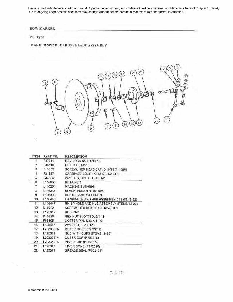
This is a dowloadable version of the manual. A partial download may not contain all pertinent information. Make sure to read Chapter 1, Safety! Due to ongoing upgrades specifications may change without notice, contact a Monosem Rep for current information.
© Monosem Inc. 2011
This is a dowloadable version of the manual. A partial download may not contain all pertinent information. Make sure to read Chapter 1, Safety! Due to ongoing upgrades specifications may change without notice, contact a Monosem Rep for current information.
© Monosem Inc. 2011
This is a dowloadable version of the manual. A partial download may not contain all pertinent information. Make sure to read Chapter 1, Safety! Due to ongoing upgrades specifications may change without notice, contact a Monosem Rep for current information.
© Monosem Inc. 2011

This is a dowloadable version of the manual. A partial download may not contain all pertinent information. Make sure to read Chapter 1, Safety! Due to ongoing upgrades specifications may change without notice, contact a Monosem Rep for current information.
© Monosem Inc. 2011

This is a dowloadable version of the manual. A partial download may not contain all pertinent information. Make sure to read Chapter 1, Safety! Due to ongoing upgrades specifications may change without notice, contact a Monosem Rep for current information.
© Monosem Inc. 2011
This is a dowloadable version of the manual. A partial download may not contain all pertinent information. Make sure to read Chapter 1, Safety! Due to ongoing upgrades specifications may change without notice, contact a Monosem Rep for current information.
© Monosem Inc. 2011
This is a dowloadable version of the manual. A partial download may not contain all pertinent information. Make sure to read Chapter 1, Safety! Due to ongoing upgrades specifications may change without notice, contact a Monosem Rep for current information.
© Monosem Inc. 2011
This is a dowloadable version of the manual. A partial download may not contain all pertinent information. Make sure to read Chapter 1, Safety! Due to ongoing upgrades specifications may change without notice, contact a Monosem Rep for current information.
© Monosem Inc. 2011
This is a dowloadable version of the manual. A partial download may not contain all pertinent information. Make sure to read Chapter 1, Safety! Due to ongoing upgrades specifications may change without notice, contact a Monosem Rep for current information.
© Monosem Inc. 2011
This is a dowloadable version of the manual. A partial download may not contain all pertinent information. Make sure to read Chapter 1, Safety! Due to ongoing upgrades specifications may change without notice, contact a Monosem Rep for current information.
© Monosem Inc. 2011
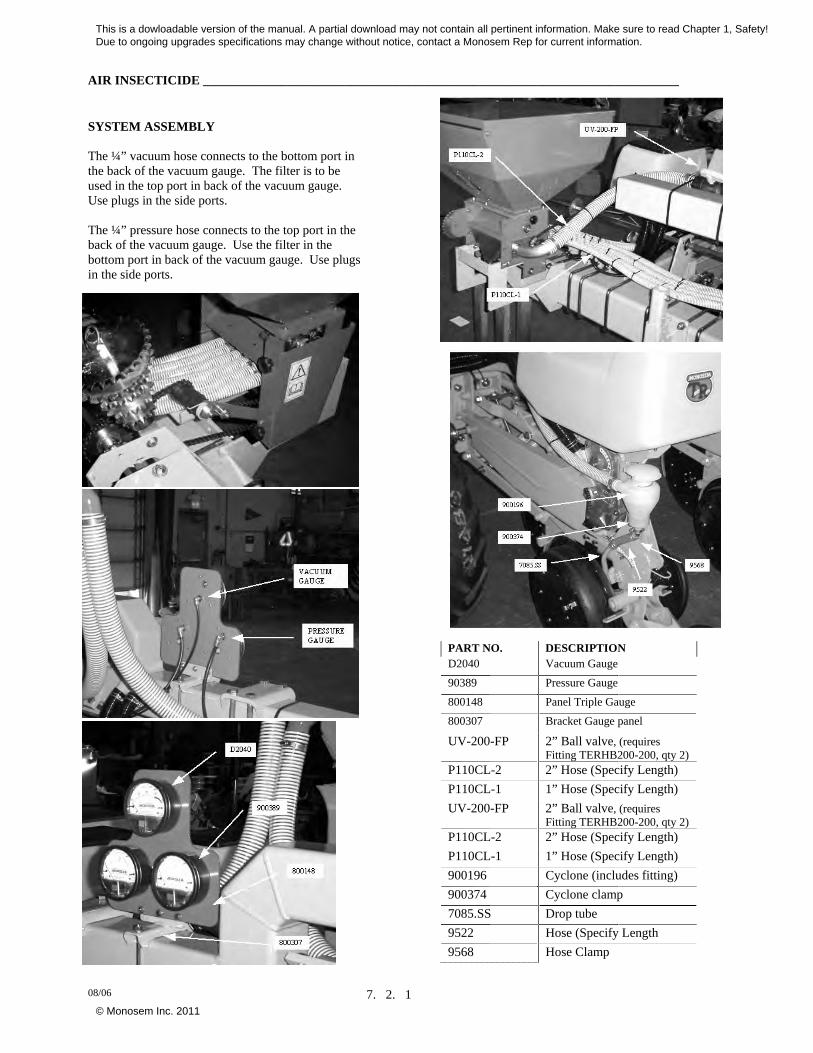
AIR INSECTICIDE __________________________________________________________________________
08/06 7. 2. 1
SYSTEM ASSEMBLY The ¼” vacuum hose connects to the bottom port in the back of the vacuum gauge. The filter is to be used in the top port in back of the vacuum gauge. Use plugs in the side ports. The ¼” pressure hose connects to the top port in the back of the vacuum gauge. Use the filter in the bottom port in back of the vacuum gauge. Use plugs in the side ports.
PART NO. DESCRIPTION D2040 Vacuum Gauge
90389 Pressure Gauge
800148 Panel Triple Gauge
800307 Bracket Gauge panel
UV-200-FP 2” Ball valve, (requires Fitting TERHB200-200, qty 2)
P110CL-2 2” Hose (Specify Length)
P110CL-1 1” Hose (Specify Length)
UV-200-FP 2” Ball valve, (requires Fitting TERHB200-200, qty 2)
P110CL-2 2” Hose (Specify Length)
P110CL-1 1” Hose (Specify Length)
900196 Cyclone (includes fitting)
900374 Cyclone clamp
7085.SS Drop tube
9522 Hose (Specify Length
9568 Hose Clamp
This is a dowloadable version of the manual. A partial download may not contain all pertinent information. Make sure to read Chapter 1, Safety! Due to ongoing upgrades specifications may change without notice, contact a Monosem Rep for current information.
© Monosem Inc. 2011
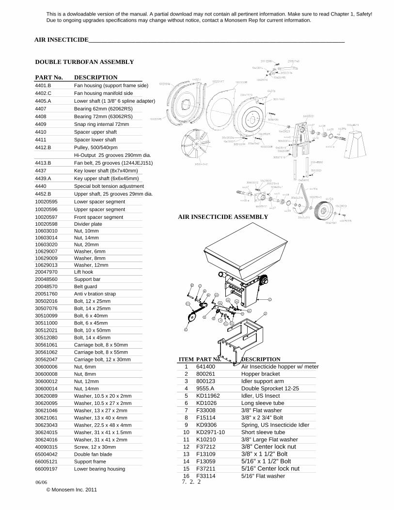
AIR INSECTICIDE__________________________________________________________________________________
DOUBLE TURBOFAN ASSEMBLY
PART No. DESCRIPTION4401.B Fan housing (support frame side)
4402.C Fan housing manifold side
4405.A Lower shaft (1 3/8" 6 spline adapter)
4407 Bearing 62mm (62062RS)
4408 Bearing 72mm (63062RS)
4409 Snap ring internal 72mm
4410 Spacer upper shaft
4411 Spacer lower shaft
4412.B Pulley, 500/540rpm
Hi-Output 25 grooves 290mm dia.
4413.B Fan belt, 25 grooves (1244JEJ151)
4437 Key lower shaft (8x7x40mm)
4439.A Key upper shaft (6x6x45mm)
4440 Special bolt tension adjustment
4452.B Upper shaft, 25 grooves 29mm dia.
10020595 Lower spacer segment
10020596 Upper spacer segment
10020597 Front spacer segment AIR INSECTICIDE ASSEMBLY10020598 Divider plate10603010 Nut, 10mm10603014 Nut, 14mm10603020 Nut, 20mm10629007 Washer, 6mm10629009 Washer, 8mm10629013 Washer, 12mm20047970 Lift hook
20048560 Support bar
20048570 Belt guard
20051760 Anti v bration strap
30502016 Bolt, 12 x 25mm
30507076 Bolt, 14 x 25mm
30510099 Bolt, 6 x 40mm
30511000 Bolt, 6 x 45mm
30512021 Bolt, 10 x 50mm
30512080 Bolt, 14 x 45mm
30561061 Carriage bolt, 8 x 50mm
30561062 Carriage bolt, 8 x 55mm
30562047 Carriage bolt, 12 x 30mm ITEM PART No. DESCRIPTION30600006 Nut, 6mm 1 641400 Air Insecticide hopper w/ meter30600008 Nut, 8mm 2 800261 Hopper bracket30600012 Nut, 12mm 3 800123 Idler support arm30600014 Nut, 14mm 4 9555.A Double Sprocket 12-2530620089 Washer, 10.5 x 20 x 2mm 5 KD11962 Idler, US Insect30620095 Washer, 10.5 x 27 x 2mm 6 KD1026 Long sleeve tube30621046 Washer, 13 x 27 x 2mm 7 F33008 3/8" Flat washer30621061 Washer, 13 x 40 x 4mm 8 F15114 3/8" x 2 3/4" Bolt30623043 Washer, 22.5 x 48 x 4mm 9 KD9306 Spring, US Insecticide Idler30624015 Washer, 31 x 41 x 1.5mm 10 KD2971-10 Short sleeve tube30624016 Washer, 31 x 41 x 2mm 11 K10210 3/8" Large Flat washer40090315 Screw, 12 x 30mm 12 F37212 3/8" Center lock nut65004042 Double fan blade 13 F13109 3/8" x 1 1/2" Bolt66005121 Support frame 14 F13059 5/16" x 1 1/2" Bolt66009197 Lower bearing housing 15 F37211 5/16" Center lock nut
16 F33114 5/16" Flat washer
13
4
23
1
56
7
90
11 12
14
7
10
15
1617
8
06/06 7. 2. 2
This is a dowloadable version of the manual. A partial download may not contain all pertinent information. Make sure to read Chapter 1, Safety! Due to ongoing upgrades specifications may change without notice, contact a Monosem Rep for current information.
© Monosem Inc. 2011
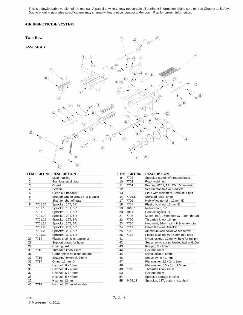
AIR INSECTICIDE SYSTEM________________________________________________________________________
Twin-Row
ASSEMBLY
ITEM PART No. DESCRIPTION ITEM PART No. DESCRIPTION1 Main housing 9 7702 Sprocker carrier w/threaded knob2 Stainless steel plate 10 7703 Rotor weldment3 Guard 11 7704 Bearing, 6201, 12x 32x 10mm wide4 Screen 12 Venturi manifold w/ 6 outlets5 Clean out trapdoor 13 Plate with weldment, 8mm stud bolt6 Shut off gate to create 4 or 6 outlet 14 7705.5 Serrated roller, 5mm7 Shaft for shut off gate 17 7706 Hub w/ locator pin, 12 mm ID8 7701.14 Sprocket, 14T, 5R 18 7707 Plastic bushing, 12 mm ID
7701.16 Sprocket, 16T, 5R 19 10107 Roller chain, 5R7701.18 Sprocket, 18T, 5R 20 10111 Connecting link, 5R7701.20 Sprocket, 20T, 5R 21 7708 Meter shaft, 15mm hex w/ 12mm thread7701.22 Sprocket, 22T, 5R 22 7709 Threaded knob, 10mm7701.24 Sprocket, 24T, 5R 23 7710 Hex shaft, 14mm w/ hub & locator pin7701.26 Sprocket, 26T, 5R 24 7711 Chain tensioner bracket7701.28 Sprocket, 28T, 5R 25 7712 Aluminum lock collar w/ set screw7701.30 Sprocket, 30T, 5R 26 7713 Plastic bushing, w/ 14 mm hex bore
27 7714 Plastic chain idler tensioner 41 Nylon locknut, 12mm w/ hole for roll pin28 Support plates for hose 42 Set screw w/ spring loaded ball end, 6mm29 Chain guard 43 Roll pin, 3 x 20mm30 7715 Threaded knob, 8mm 44 Hex nut, 6mm31 Corner plate for clean out door 45 Nylon locknut, 5mm32 7716 Snapring, external, 24mm 46 Set screw, 6 x 1 mm33 7717 O ring, 12mm ID 47 Flat washer, 12 x 24 x 2mm35 Hex bolt, 8 x 16mm 48 Flat washer, 6.5 x 15 x 1.5mm36 Hex bolt, 8 x 45mm 49 7719 Threaded knob, 6mm37 Hex bolt, 6 x 16mm 53 Hex nut, 8mm38 Hex bolt, 5 x 40mm 54 Sprocket storage bracket39 Hex nut, 12mm 55 4426.18 Sprocket, 18T, bottom hex shaft40 7718 Hex nut, 12mm w/ washer
01/06 7. 2. 3
This is a dowloadable version of the manual. A partial download may not contain all pertinent information. Make sure to read Chapter 1, Safety! Due to ongoing upgrades specifications may change without notice, contact a Monosem Rep for current information.
© Monosem Inc. 2011
AIR INSECTICIDE SYSTEM________________________________________________________________
Twin-Row
AIR INSECTICIDE APPLICATION RATES
TEMIK 15G Gypsum
Double Sprocket: 12
Sprockets on insecticide meter box
Driver 14 14 14 14 28 30 22 26
Driven 30 26 22 16 30 28 18 18
Row Spacing 36" 8.9 10.3 12.2 16.8 17.9 20.5 23.4 27.7
38" 8.5 9.8 11.5 15.9 16.9 19.4 22.2 26.2
40" 8 9.3 11 15.1 16.1 18.5 21.1 24.9
TEMIK 15G GritDouble Sprocket: 12Sprockets on insecticide meter box
Driver 14 14 14 14 28 30 22 26Driven 30 26 22 16 30 28 18 18
Row Spacing 36" 3.6 4.2 4.9 6.8 7.2 8.3 9.4 11.138" 3.4 3.9 4.7 6.4 6.8 7.8 8.9 10.640" 3.2 3.7 4.4 6.1 6.5 7.4 8.5 10
COUNTER 15GDouble Sprocket: 12Sprockets on insecticide meter box
Driver 14 14 14 14 28 30 22 26Driven 30 26 22 16 30 28 18 18
Row Spacing 36" 5.4 6.2 7.4 10.1 10.8 12.4 14.1 16.738" 5.1 5.9 7 9.6 10.2 11.7 13.4 15.840" 4.9 5.6 6.6 9.1 9.7 11.2 12.7 15
THIMET 20GDouble Sprocket: 12Sprockets on insecticide meter box
Driver 14 14 14 14 28 30 22 26Driven 30 26 22 16 30 28 18 18
Row Spacing 36" 5.5 6.3 7.5 10.2 10.9 12.5 14.3 16.938" 5.2 6 7.1 9.7 10.4 11.9 13.6 1640" 4.9 5.7 6.7 9.2 9.8 11.3 12.9 15.2
Double sprocket on hex shaft and changeable sprockets on 6 outlet insecticide metering boxes.
Rates are in pounds per acre
These settings are theoretical and approximate. Actual output may vary.
03/06 7. 2. 4
This is a dowloadable version of the manual. A partial download may not contain all pertinent information. Make sure to read Chapter 1, Safety! Due to ongoing upgrades specifications may change without notice, contact a Monosem Rep for current information.
© Monosem Inc. 2011
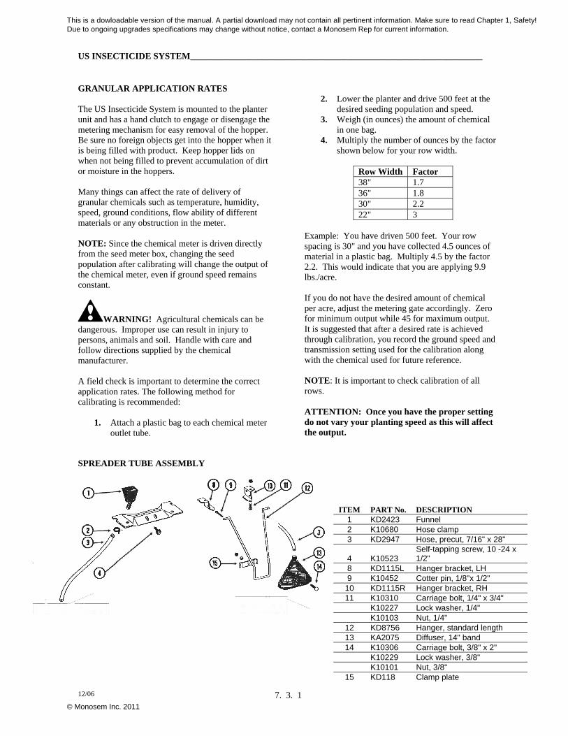
US INSECTICIDE SYSTEM_________________________________________________________________
12/06 7. 3. 1
GRANULAR APPLICATION RATES The US Insecticide System is mounted to the planter unit and has a hand clutch to engage or disengage the metering mechanism for easy removal of the hopper. Be sure no foreign objects get into the hopper when it is being filled with product. Keep hopper lids on when not being filled to prevent accumulation of dirt or moisture in the hoppers. Many things can affect the rate of delivery of granular chemicals such as temperature, humidity, speed, ground conditions, flow ability of different materials or any obstruction in the meter. NOTE: Since the chemical meter is driven directly from the seed meter box, changing the seed population after calibrating will change the output of the chemical meter, even if ground speed remains constant.
WARNING! Agricultural chemicals can be dangerous. Improper use can result in injury to persons, animals and soil. Handle with care and follow directions supplied by the chemical manufacturer. A field check is important to determine the correct application rates. The following method for calibrating is recommended:
1. Attach a plastic bag to each chemical meter outlet tube.
2. Lower the planter and drive 500 feet at the desired seeding population and speed.
3. Weigh (in ounces) the amount of chemical in one bag.
4. Multiply the number of ounces by the factor shown below for your row width.
Row Width Factor 38" 1.7 36" 1.8 30" 2.2 22" 3
Example: You have driven 500 feet. Your row spacing is 30" and you have collected 4.5 ounces of material in a plastic bag. Multiply 4.5 by the factor 2.2. This would indicate that you are applying 9.9 lbs./acre. If you do not have the desired amount of chemical per acre, adjust the metering gate accordingly. Zero for minimum output while 45 for maximum output. It is suggested that after a desired rate is achieved through calibration, you record the ground speed and transmission setting used for the calibration along with the chemical used for future reference. NOTE: It is important to check calibration of all rows. ATTENTION: Once you have the proper setting do not vary your planting speed as this will affect the output.
SPREADER TUBE ASSEMBLY
ITEM PART No. DESCRIPTION 1 KD2423 Funnel 2 K10680 Hose clamp 3 KD2947 Hose, precut, 7/16" x 28"
4 K10523 Self-tapping screw, 10 -24 x 1/2"
8 KD1115L Hanger bracket, LH 9 K10452 Cotter pin, 1/8"x 1/2"
10 KD1115R Hanger bracket, RH 11 K10310 Carriage bolt, 1/4" x 3/4" K10227 Lock washer, 1/4" K10103 Nut, 1/4"
12 KD8756 Hanger, standard length 13 KA2075 Diffuser, 14" band 14 K10306 Carriage bolt, 3/8" x 2" K10229 Lock washer, 3/8" K10101 Nut, 3/8"
15 KD118 Clamp plate
This is a dowloadable version of the manual. A partial download may not contain all pertinent information. Make sure to read Chapter 1, Safety! Due to ongoing upgrades specifications may change without notice, contact a Monosem Rep for current information.
© Monosem Inc. 2011
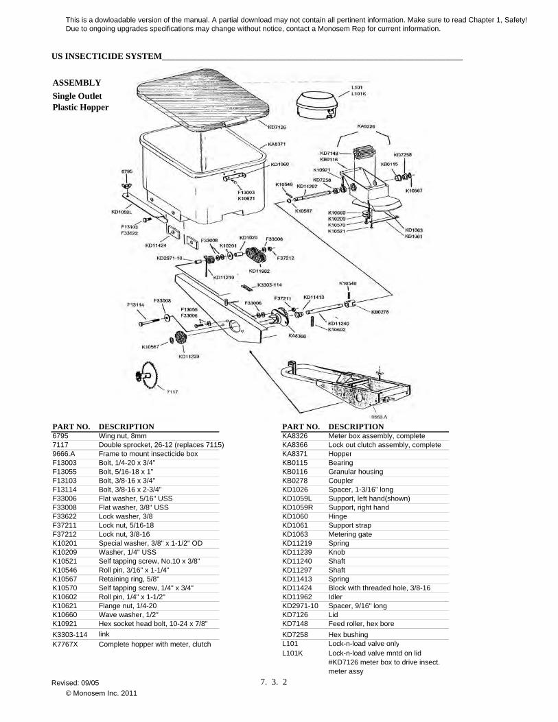
US INSECTICIDE SYSTEM____________________________________________________________________
ASSEMBLY
PART NO. DESCRIPTION PART NO. DESCRIPTION6795 Wing nut, 8mm KA8326 Meter box assembly, complete7117 Double sprocket, 26-12 (replaces 7115) KA8366 Lock out clutch assembly, complete9666.A Frame to mount insecticide box KA8371 HopperF13003 Bolt, 1/4-20 x 3/4" KB0115 BearingF13055 Bolt, 5/16-18 x 1" KB0116 Granular housingF13103 Bolt, 3/8-16 x 3/4" KB0278 CouplerF13114 Bolt, 3/8-16 x 2-3/4" KD1026 Spacer, 1-3/16" longF33006 Flat washer, 5/16" USS KD1059L Support, left hand(shown)F33008 Flat washer, 3/8" USS KD1059R Support, right handF33622 Lock washer, 3/8 KD1060 HingeF37211 Lock nut, 5/16-18 KD1061 Support strapF37212 Lock nut, 3/8-16 KD1063 Metering gateK10201 Special washer, 3/8" x 1-1/2" OD KD11219 SpringK10209 Washer, 1/4" USS KD11239 KnobK10521 Self tapping screw, No.10 x 3/8" KD11240 ShaftK10546 Roll pin, 3/16" x 1-1/4" KD11297 ShaftK10567 Retaining ring, 5/8" KD11413 SpringK10570 Self tapping screw, 1/4" x 3/4" KD11424 Block with threaded hole, 3/8-16K10602 Roll pin, 1/4" x 1-1/2" KD11962 IdlerK10621 Flange nut, 1/4-20 KD2971-10 Spacer, 9/16" longK10660 Wave washer, 1/2" KD7126 LidK10921 Hex socket head bolt, 10-24 x 7/8" KD7148 Feed roller, hex bore
K3303-114 link KD7258 Hex bushingK7767X Complete hopper with meter, clutch L101 Lock-n-load valve only
L101K Lock-n-load valve mntd on lid #KD7126 meter box to drive insect. meter assy
Single Outlet Plastic Hopper
Revised: 09/05 7. 3. 2
This is a dowloadable version of the manual. A partial download may not contain all pertinent information. Make sure to read Chapter 1, Safety! Due to ongoing upgrades specifications may change without notice, contact a Monosem Rep for current information.
© Monosem Inc. 2011

MICROSEM MICROGRANULAR INSECTICIDE SYSTEM _______________________________________ Twin-Row
04/05 7. 4. 1
MICROSEM SYSTEM The microsem system meters microgranular products such as insecticide and herbicide with precision. The system is ground driven and has a positive displacement. The output is set by a transmission that is unaffected by a change in planting speed. The microsem system is mounted to the toolbar frame with support brackets to reduce weight on the planter unit. The microsem system with auger is equipped with a telescoping outlet, and its output starts from a minimum of 2-3 lbs/acre. Each microsem hopper has a 33 lb. capacity and can be used with a double outlet for two row units or with a single outlet for one row unit. The drive sprocket is mounted on the upper hex shaft. The hoses direct the granular product directly between the disc openers via drop tubes, or behind the disc openers via a spreader tube. TROUBLE SHOOTING PROBLEM: Variations between the outlets or metering boxes. POSSIBLE CAUSE:
There may be foreign material mixed with the product
ATTENTION! there may be moisture in the product.
The metering unit may have been assembled improperly.
The outlet chute may be warped. The hose may be too long or bent, causing
the hose to clog. INSECTICIDE DROP TUBE 7085.SD Mounts on the right hand side of the unit, towards the front with a single bolt. It then curves down thru a notch cut into the shield covering the front of the double disc opener. It deposits material into the seed trench in front of the seed tube. This tube is used on the set back unit on twin-row machines. The top of the tube curves to the left to accept the feeder hose coming down on the left hand side of the parallel linkage.
7085. SU Mounts on the right hand side of the unit, towards the front with a single bolt. It then curves down thru a notch cut into the shield covering the front of the double disc opener. It deposits material into the seed trench in front of the seed tube. This tube is used on the set back unit on twin-row machines. The top of the tube extends straight up to accept the feeder hose coming through the middle of the parallel linkage. 7085.DA Mounts on the right hand side of the unit, with the same bolts that attach the disc scraper. It deposits material down in the seed trench behind the seed tube. The top of the tube points straight up.
7085.GA Mounts on the left hand side of the unit, with the same bolts that attach the disc scraper. It deposits material down in the seed trench behind the seed tube. The top of the tube points straight up.
7085.SS Mounts on the left hand side of the
unit, with the same bolts that attach the disc scraper. It deposits material down in the seed trench behind the seed tube. The top of the tube curves towards the rear to accept the feeder hose from the Air Insecticide System.
This is a dowloadable version of the manual. A partial download may not contain all pertinent information. Make sure to read Chapter 1, Safety! Due to ongoing upgrades specifications may change without notice, contact a Monosem Rep for current information.
© Monosem Inc. 2011
MICROSEM MICROGRANULAR INSECTICIDE SYSTEM _______________________________________ Twin-Row
04/05 7. 4. 2
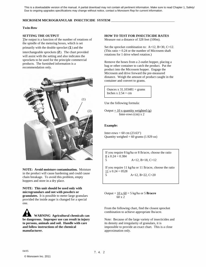
SETTING THE OUTPUT The output is a function of the number of rotations of the spindle of the metering boxes, which is set primarily with the double sprocket (1) and the
interchangeable sprockets (2). The chart provided will assist with the setting and also indicates the sprockets to be used for the principle commercial products. The furnished information is a recommendation only.
NOTE: Avoid moisture contamination. Moisture in the product will cause hardening and could cause chain breakage. To avoid this problem, empty hoppers and store in a dry place. NOTE: This unit should be used only with microgranulars and not with powders or granulates. It is possible to meter large granulars provided the inside auger is changed for a special one.
WARNING Agricultural chemicals can be dangerous. Improper use can result in injury to persons, animals and soil. Handle with care and follow instructions of the chemical manufacturer.
HOW TO TEST FOR INSECTICIDE RATES Measure out a distance of 328 feet (100m). Set the sprocket combination to: A=12, B=30, C=12. (This ratio = 0.24 or the number of Microsem shaft rotations for 1 drive wheel rotation.) Remove the hoses from a 2-outlet hopper, placing a bag or other container to catch the product. Put the product into the Microsem hopper. Engage the Microsem and drive forward the pre-measured distance. Weigh the amount of product caught in the container and convert to grams.
Use the following formula: Output = 10 x quantity weighted (g) Inter-rows (cm) x 2 Example: Inter-rows = 60 cm (23.63") Quantity weighed = 60 grams (1.929 oz)
Output = 10 x 60 = 5 kg/ha or 5 lb/acre 60 x 2 From the following chart, find the closest sprocket combination to achieve appropriate lbs/acre. Note: Because of the large variety of insecticides and its density and irregularity of granulars, it is impossible to provide an exact chart. This is a close approximation only.
Ounces x 31.103481 = grams Inches x 2.54 = cm
If you require 8 kg/ha or 8 lb/acre, choose the ratio 8 x 0.24 = 0.384 5 A=12, B=18, C=12 If you require 11 kg/ha or 11 lb/acre, choose the ratio 11 x 0.24 = 0528 5 A=12, B=22, C=20
(1)
(2)
This is a dowloadable version of the manual. A partial download may not contain all pertinent information. Make sure to read Chapter 1, Safety! Due to ongoing upgrades specifications may change without notice, contact a Monosem Rep for current information.
© Monosem Inc. 2011
MICROSEM MICROGRANULAR INSECTICIDE SYSTEM _______________________________________ Twin-Row
04/05 7. 4. 3
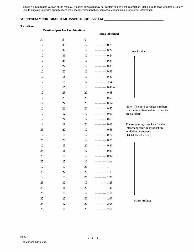
Possible Sprocket Combinations
Ratios Obtained Less Product
A B C
12 35 12 ---------- 0.21
12 32 12 ---------- 0.22
12 30 12 ---------- 0.24
12 25 12 ---------- 0.29
12 22 12 ---------- 0.33
12 20 12 ---------- 0.36
12 18 12 ---------- 0.40
12 16 12 ---------- 0.45
12 15 12 ---------- 0.48 or
12 25 20 ---------- 0.48
12 23 20 ---------- 0.51
12 22 20 ---------- 0.54
12 21 20 ---------- 0.57
12 12 12 ---------- 0.60
12 24 12 ---------- 0.63
12 18 21 ---------- 0.66
25 22 12 ---------- 0.68
12 10 12 ---------- 0.72
25 20 12 ---------- 0.75
12 15 20 ---------- 0.80
25 18 12 ---------- 0.83
25 16 12 ---------- 0.94
25 15 12 ---------- 1 or
12 12 20 ---------- 1
25 22 20 ---------- 1.13
12 10 20 ---------- 1.20
25 12 12 ---------- 1.25
25 18 20 ---------- 1.40
25 10 12 ---------- 1.50
25 15 20 ---------- 1.66
25 12 20 ---------- 2.08
25 10 20 ---------- 2.50
Note: The bold sprocket numbers for the interchangeable B sprocket are standard. The remaining sprockets for the interchangeable B sprocket are available on request. (13-14-16-23-26-35)
More Product
This is a dowloadable version of the manual. A partial download may not contain all pertinent information. Make sure to read Chapter 1, Safety! Due to ongoing upgrades specifications may change without notice, contact a Monosem Rep for current information.
© Monosem Inc. 2011
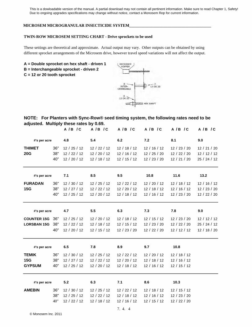
MICROSEM MICROGRANULAR INSECTICIDE SYSTEM_________________________________________
TWIN-ROW MICROSEM SETTING CHART - Drive sprockets to be used
These settings are theoretical and approximate. Actual output may vary. Other outputs can be obtained by using different sprocket arrangements of the Microsem drive, however travel speed variations will not affect the output.
A = Double sprocket on hex shaft - driven 1B = Interchangeable sprocket - driven 2C = 12 or 20 tooth sprocket
A / B / C A / B / C A / B / C A / B / C A / B / C A / B / C
#'s per acre
THIMET 36" 12 / 25 / 12 12 / 22 / 12 12 / 18 / 12 12 / 16 / 12 12 / 23 / 20 12 / 21 / 20
20G 38" 12 / 22 / 12 12 / 20 / 12 12 / 16 / 12 12 / 25 / 20 12 / 22 / 20 12 / 12 / 12
40" 12 / 20 / 12 12 / 18 / 12 12 / 15 / 12 12 / 23 / 20 12 / 21 / 20 25 / 24 / 12
#'s per acre
FURADAN 36" 12 / 30 / 12 12 / 25 / 12 12 / 22 / 12 12 / 20 / 12 12 / 18 / 12 12 / 16 / 12
15G 38" 12 / 27 / 12 12 / 22 / 12 12 / 20 / 12 12 / 18 / 12 12 / 16 / 12 12 / 23 / 20
40" 12 / 25 / 12 12 / 20 / 12 12 / 18 / 12 12 / 16 / 12 12 / 23 / 20 12 / 22 / 20
#'s per acre
COUNTER 15G 36" 12 / 25 / 12 12 / 20 / 12 12 / 18 / 12 12 / 15 / 12 12 / 23 / 20 12 / 12 / 12
LORSBAN 15G 38" 12 / 22 / 12 12 / 18 / 12 12 / 15 / 12 12 / 23 / 20 12 / 22 / 20 25 / 24 / 12
40" 12 / 20 / 12 12 / 15 / 12 12 / 23 / 20 12 / 22 / 20 12 / 12 / 12 12 / 18 / 20
#'s per acre
TEMIK 36" 12 / 30 / 12 12 / 25 / 12 12 / 22 / 12 12 / 20 / 12 12 / 18 / 12
15G 38" 12 / 27 / 12 12 / 22 / 12 12 / 20 / 12 12 / 18 / 12 12 / 16 / 12
GYPSUM 40" 12 / 25 / 12 12 / 20 / 12 12 / 18 / 12 12 / 16 / 12 12 / 15 / 12
#'s per acre
AMEBIN 36" 12 / 30 / 12 12 / 25 / 12 12 / 22 / 12 12 / 18 / 12 12 / 15 / 12
38" 12 / 25 / 12 12 / 22 / 12 12 / 18 / 12 12 / 16 / 12 12 / 23 / 20
40" 12 / 22 / 12 12 / 18 / 12 12 / 16 / 12 12 / 15 / 12 12 / 22 / 20
10.8 11.6 13.2
10.8
7.8 9.0
4.8 5.4 6.2
4.7 5.5 6.3
7.1 8.5 9.5
7.3
6.5 7.8 8.9 9.7
10.35.2 6.3 7.1 8.6
NOTE: For Planters with Sync-Row® seed timing system, the following rates need to be adjusted. Multiply these rates by 0.69.
7.2 8.1 9.0
7. 4. 4
This is a dowloadable version of the manual. A partial download may not contain all pertinent information. Make sure to read Chapter 1, Safety! Due to ongoing upgrades specifications may change without notice, contact a Monosem Rep for current information.
© Monosem Inc. 2011

MICROSEM MICROGRANULAR INSECTICIDE SYSTEM_________________________________________
TWIN-ROW MICROSEM SETTING CHART - Drive sprockets to be used
These settings are theoretical and approximate. Actual output may vary. Other outputs can be obtained by using different sprocket arrangements of the Microsem drive, however travel speed variations will not affect the output.
A / B / C A / B / C A / B / C A / B / C A / B / C A / B / C
#'s per acre
TEMIK 15G 36" 12 / 18 / 12 12 / 15 / 12 12 / 23 / 12 12 / 22 / 20 12 / 12 / 12 12 / 18 / 20
CORNCOB 38" 12 / 15 / 12 12 / 23 / 20 12 / 22 / 20 12 / 12 / 12 12 / 24 / 12 25 / 22 / 12
GRIT 40" 12 / 23 / 20 12 / 22 / 20 12 / 12 / 12 12 / 24 / 12 12 / 18 / 20 12 / 10 / 12
#'s per acre
25 / 22 / 12 25 / 20 / 12
12 / 10 / 12 12 / 15 / 20
25 / 20 / 12 25 / 18 / 12
#'s per acre
ZENECA FORCE 36" 12 / 20 / 12 12 / 18 / 12 12 / 15 / 12 12 / 12 / 12 12 / 12 / 12 12 / 18 / 20
3G 38" 12 / 18 / 12 12 / 15 / 12 12 / 23 / 20 12 / 12 / 12 25 / 24 / 12 25 / 22 / 12
40" 12 / 16 / 12 12 / 23 / 20 12 / 22 / 20 24 / 24 / 12 12 / 18 / 20 25 / 20 / 12
#'s per acre
25 / 20 / 12
12 / 15 / 20
12 / 18 / 12
#'s per acre
RIDOMIL 36" 12 / 22 / 12 12 / 20 / 12 12 / 18 / 12 12 / 15 / 12 12 / 22 / 20 12 / 12 / 12
GOLD GR 38" 12 / 20 / 12 12 / 18 / 12 12 / 15 / 12 12 / 23 / 20 12 / 12 / 12 12 / 18 / 20
PC11G 40" 12 / 18 / 12 12 / 15 / 12 12 / 23 / 20 12 / 22 / 20 12 / 18 / 20 25 / 22 / 12
#'s per acre
12 / 18 / 20
25 / 22 / 12
25 / 20 / 12
#'s per acre
GOLD PC 36" 12 / 25 / 12 12 / 22 / 12 12 / 20 / 12 12 / 18 / 12 12 / 15 / 12 12 / 22 / 20
38" 12 / 22 / 12 12 / 20 / 12 12 / 18 / 12 12 / 15 / 12 12 / 22 / 20 12 / 12 / 12
40" 12 / 20 / 12 12 / 18 / 12 12 / 15 / 12 12 / 22 / 20 12 / 12 / 12 12 / 18 / 20
8.4
8.1
6.65.8
6.0
7.4
5.1 5.8 6.4 7.1 8.5 9.5
4.0 4.4 4.9
6.7 7.4
4.4 5.3
4.0 4.5 5.4 6.1
5.7
7.6 8.3
NOTE: For Planters with Sync-Row® seed timing system, the following rates need to be adjusted. Multiply these rates by 0.69.
6.7 7.3
7. 4. 5
This is a dowloadable version of the manual. A partial download may not contain all pertinent information. Make sure to read Chapter 1, Safety! Due to ongoing upgrades specifications may change without notice, contact a Monosem Rep for current information.
© Monosem Inc. 2011
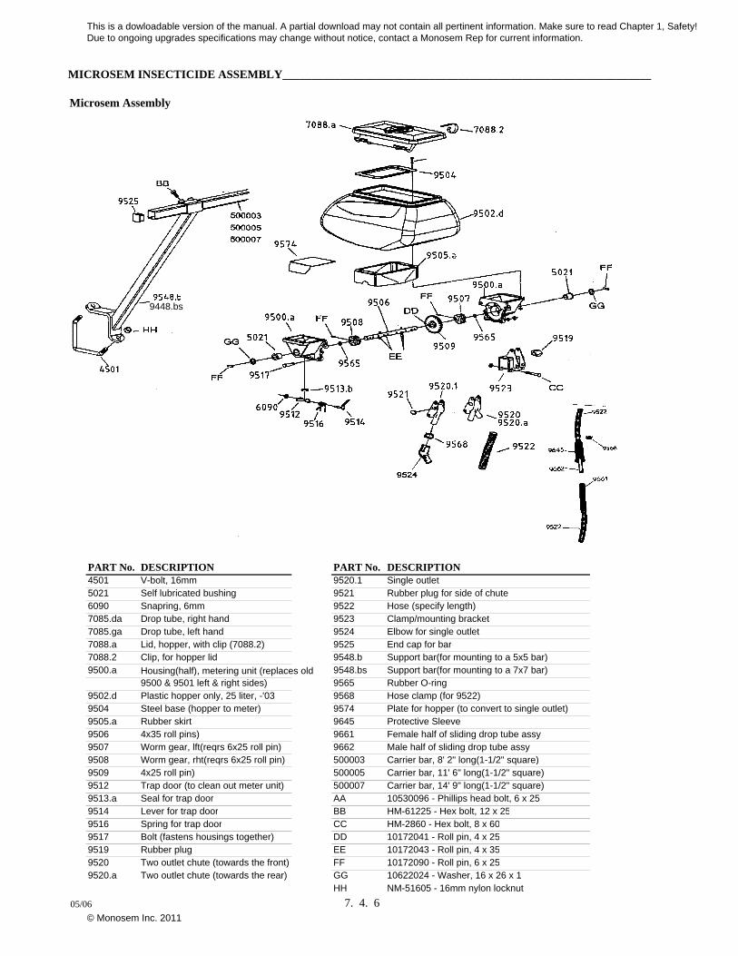
MICROSEM INSECTICIDE ASSEMBLY_______________________________________________________________
Microsem Assembly
9448.bs
PART No. DESCRIPTION PART No. DESCRIPTION4501 V-bolt, 16mm 9520.1 Single outlet5021 Self lubricated bushing 9521 Rubber plug for side of chute6090 Snapring, 6mm 9522 Hose (specify length)7085.da Drop tube, right hand 9523 Clamp/mounting bracket7085.ga Drop tube, left hand 9524 Elbow for single outlet7088.a Lid, hopper, with clip (7088.2) 9525 End cap for bar7088.2 Clip, for hopper lid 9548.b Support bar(for mounting to a 5x5 bar)9500.a Housing(half), metering unit (replaces old 9548.bs Support bar(for mounting to a 7x7 bar)
9500 & 9501 left & right sides) 9565 Rubber O-ring9502.d Plastic hopper only, 25 liter, -'03 9568 Hose clamp (for 9522)9504 Steel base (hopper to meter) 9574 Plate for hopper (to convert to single outlet)9505.a Rubber skirt 9645 Protective Sleeve9506 4x35 roll pins) 9661 Female half of sliding drop tube assy9507 Worm gear, lft(reqrs 6x25 roll pin) 9662 Male half of sliding drop tube assy9508 Worm gear, rht(reqrs 6x25 roll pin) 500003 Carrier bar, 8' 2" long(1-1/2" square)9509 4x25 roll pin) 500005 Carrier bar, 11' 6" long(1-1/2" square)9512 Trap door (to clean out meter unit) 500007 Carrier bar, 14' 9" long(1-1/2" square)9513.a Seal for trap door AA 10530096 - Phillips head bolt, 6 x 259514 Lever for trap door BB HM-61225 - Hex bolt, 12 x 259516 Spring for trap door CC HM-2860 - Hex bolt, 8 x 609517 Bolt (fastens housings together) DD 10172041 - Roll pin, 4 x 259519 Rubber plug EE 10172043 - Roll pin, 4 x 359520 Two outlet chute (towards the front) FF 10172090 - Roll pin, 6 x 259520.a Two outlet chute (towards the rear) GG 10622024 - Washer, 16 x 26 x 1
HH NM-51605 - 16mm nylon locknut
05/06 7. 4. 6
This is a dowloadable version of the manual. A partial download may not contain all pertinent information. Make sure to read Chapter 1, Safety! Due to ongoing upgrades specifications may change without notice, contact a Monosem Rep for current information.
© Monosem Inc. 2011

MICROSEM TRANSMISSION______________________________________________________________________
Twin-Row
ITEM PART No. DESCRIPTION31 H-4300 Hex head bolt, 1/2 -13 x3"32 N-4000 Nut, 1/2 -1333 9559 Bushing
ITEM PART No. DESCRIPTION 34 9557 Lynch pin1 9562 Chain roller 35 W-5410 Flat washer, 5/8 SAE2 9554.21 Interchangeable sprocket, 30T 36 10172091 Roll pin, 6 x 303 9554.16 Interchangeable sprocket, 25T 37 10172090 Roll pin, 6 x 254 9554.13 Interchangeable sprocket, 22T 38 10170065 Roll pin, 5 x 305 9554.9 Interchangeable sprocket, 18T 39 9158 Compression spring6 9554.3 Interchangeable sprocket, 12T 40 CB-2221 Carriage head bolt, 3/8 -16 x 1 1/2"7 9554.6 Interchangeable sprocket, 15T 42 E2007 Mounting strap to 7 x 7 toolbar8 H-3320 Hex head bolt, 3/8" -16 x 3 1/2" 43 HM-2865 Hex head bolt, 8 x 60mm9 H-3410 Hex head bolt, 3/8" -16 x 4" 45 NM-1801 Nut, 8mm
10 5021 Self lubricated bushing 46 W-2210 Flat washer, 3/8, USS11 E2002 Housing to hold nylon bushing 47 N-2101 Nylon locknut, 3/8 -1612 9280 Nylon support bushing 48 7150 Spring13 10624014 Flat washer, 31x 41x 1 50 4647.S U Bolt, 7 x 7, 3/8 -1614 4329.A Snapring 44mm 51 9553.E Upper drive chain, 5R, 99 links for 15 KD1026 Sleeve, 1 3/16" long 12T driver sprocket, 103 links for 20T16 E2004 Spacer, 1" long 52 9553.F Lower drive chain, 5R, 60 links for 17 E2005 Spacer, .6" long 25T driver spricket, 54 links for 12T18 7157 Spring 53 9606.A Sprocket, square drive, 20T19 KD11962 Chain idler, plastic 54 9651.085 Female drive conductor tube, 33 1/2"20 CB-4411 Carriage head bolt, 1/2 -13 x 1 1/2" 55 9555.A Double drive sprocket, hex bore, 12- 25T21 N-2300 Rev lock nut, 1/2 -13 56 4520 7/8" Hex shaft22 9612 Intermediate shaft 57 9650.085 Male drive connector tube, 33 1/2"23 10622024 Flat washer, 16.5 x26 x1 58 9549.125 Carrier bar, 1 1/2" sq., specify length24 9552 Spacer/driver for sprocket 59 E1011 Support bracket with offset25 9654 Double intermediate sprocket, 12- 20T 60 E2001 Transmission main frame30 E2003 Spacer, 1.4" long 61 E1010 Support bracket
08/06 7. 4. 7
This is a dowloadable version of the manual. A partial download may not contain all pertinent information. Make sure to read Chapter 1, Safety! Due to ongoing upgrades specifications may change without notice, contact a Monosem Rep for current information.
© Monosem Inc. 2011
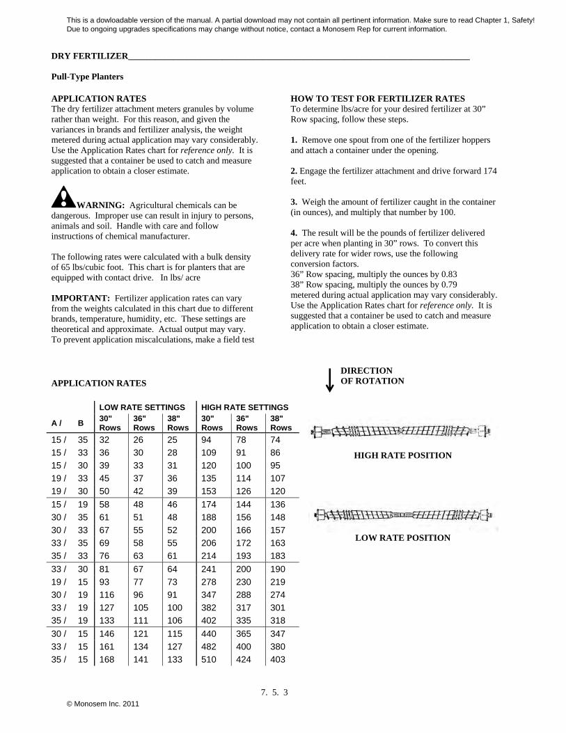
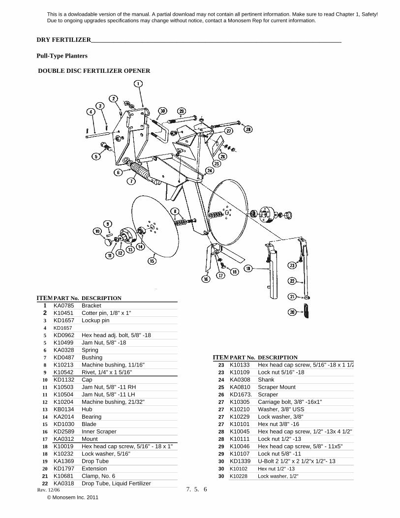
DRY FERTILIZER____________________________________________________________________________ Pull-Type Planters
7. 5. 1
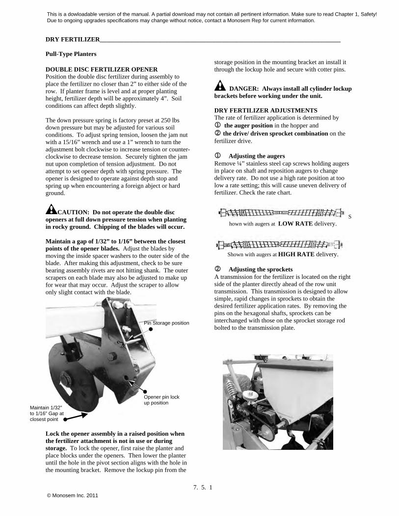
DOUBLE DISC FERTILIZER OPENER Position the double disc fertilizer during assembly to place the fertilizer no closer than 2” to either side of the row. If planter frame is level and at proper planting height, fertilizer depth will be approximately 4”. Soil conditions can affect depth slightly. The down pressure spring is factory preset at 250 lbs down pressure but may be adjusted for various soil conditions. To adjust spring tension, loosen the jam nut with a 15/16” wrench and use a 1” wrench to turn the adjustment bolt clockwise to increase tension or counter-clockwise to decrease tension. Securely tighten the jam nut upon completion of tension adjustment. Do not attempt to set opener depth with spring pressure. The opener is designed to operate against depth stop and spring up when encountering a foreign abject or hard ground.
CAUTION: Do not operate the double disc openers at full down pressure tension when planting in rocky ground. Chipping of the blades will occur. Maintain a gap of 1/32” to 1/16” between the closest points of the opener blades. Adjust the blades by moving the inside spacer washers to the outer side of the blade. After making this adjustment, check to be sure bearing assembly rivets are not hitting shank. The outer scrapers on each blade may also be adjusted to make up for wear that may occur. Adjust the scraper to allow only slight contact with the blade.
Lock the opener assembly in a raised position when the fertilizer attachment is not in use or during storage. To lock the opener, first raise the planter and place blocks under the openers. Then lower the planter until the hole in the pivot section aligns with the hole in the mounting bracket. Remove the lockup pin from the
storage position in the mounting bracket an install it through the lockup hole and secure with cotter pins.
DANGER: Always install all cylinder lockup brackets before working under the unit. DRY FERTILIZER ADJUSTMENTS The rate of fertilizer application is determined by the auger position in the hopper and the drive/ driven sprocket combination on the fertilizer drive. Adjusting the augers Remove ¼” stainless steel cap screws holding augers in place on shaft and reposition augers to change delivery rate. Do not use a high rate position at too low a rate setting; this will cause uneven delivery of fertilizer. Check the rate chart.
Shown with augers at LOW RATE delivery.
Shown with augers at HIGH RATE delivery.
Adjusting the sprockets A transmission for the fertilizer is located on the right side of the planter directly ahead of the row unit transmission. This transmission is designed to allow simple, rapid changes in sprockets to obtain the desired fertilizer application rates. By removing the pins on the hexagonal shafts, sprockets can be interchanged with those on the sprocket storage rod bolted to the transmission plate.
Pin Storage position
Opener pin lock up position
Maintain 1/32” to 1/16” Gap at closest point
This is a dowloadable version of the manual. A partial download may not contain all pertinent information. Make sure to read Chapter 1, Safety! Due to ongoing upgrades specifications may change without notice, contact a Monosem Rep for current information.
© Monosem Inc. 2011
DRY FERTILIZER____________________________________________________________________________ Pull-Type Planters
7. 5. 2
Chain tension is controlled by a spring loaded idler. This idler is adjusted with a ratchet arm located to the inside of the transmission. This arm has a release position to remove spring tension for replacing sprockets. The amount of spring tension on the chain can be controlled by the ratchet arm. Use the fertilizer application chart to select the correct sprocket combinations. IMPORTANT: After each sprocket combination adjustment, make a field check to be sure you are applying fertilizer at the desired rate. APPLICATION RATES The dry fertilizer attachment meters granules by volume rather than weight. For this reason, and given the variances in brands and fertilizer analysis, the weight metered during actual application may vary considerably. Use the Application Rates chart for reference only. It is suggested that a container be used to catch and measure application to obtain a closer estimate.
WARNING: Agricultural chemicals can be dangerous. Improper use can result in injury to persons, animals and soil. Handle with care and follow instructions of chemical manufacturer. The following rates were calculated with a bulk density of 65 lbs/cubic foot. This chart is for planters that are equipped with contact drive. In lbs/ acre IMPORTANT: Fertilizer application rates can vary from the weights calculated in this chart due to different brands, temperature, humidity, etc. These settings are theoretical and approximate. Actual output may vary. To prevent application miscalculations, make a field test
CLEANING Since most fertilizers absorb moisture, it is important that you keep fertilizer dry during use and storage. In addition to waste, deposits of fertilizer left in the hopper can cause metal corrosion. Hoppers should be emptied at the end of each day’s use. At the end of the planting season, or when fertilizer attachment is not going to be used for a period of time, the hoppers should be disassembled, cleaned and metal surfaces coated with a rust preventative.
IMPORTANT: If fertilizer is placed too close to the seed, it may cause germination or seedling damage especially if used in amounts in excess of fertilizer manufacturer’s recommendations. Check
with your fertilizer dealer or manufacturer for the correct amount and placement. The dry fertilizer hoppers are designed to tip forward for dumping and ease of cleaning. To dump hoppers, first disconnect the drive shaft from the transmission or adjacent hopper. LOOSEN HOES CLAMPS AND REMOVE HOSES FROM EACH HOPPER.
1. Remove the two rear ½” x 1 ¼” cap screws from between hopper support and opener mounting bar. Loosen the two front ½” x 1 ¼” cap screws. Rotate hopper lids to the backside of hopper and carefully tip hopper forward. After dumping contents, flush all loose fertilizer from the hopper and hoses. To disassemble auger assemblies, remove ¼” cotter pin and bearing from one end of the shaft. Pull auger assembly from opposite end of hopper. Remove stainless steel cap screws from auger shaft and remove all auger components for cleaning. Coat all parts with rust preventative before reassembly. Reinstall auger halves in proper low rate or high rate position.
2. To reassemble, slide auger assembly through the outlet housing back into the hopper. Secure in place by reinstalling the bearing and cotter pin.
3. auger installation by rotating shaft in the direction of planter travel to see that the spirals on the auger move toward the ends of the hopper. If not, remove auger assembly, turn 180° and reinstall.
4. Be certain that the augers turn freely. If not, loosen the 5/16” carriage bolts in the outlet housings, rotate the auger several times and retighten the 5/16” carriage bolts.
5. This should allow the housings to realign them selves with the auger.
6. Install auger baffles over the augers and secure in place with two hairpin clips in each hopper. Do not operate fertilizer attachment without auger baffles in place.
IMPORTANT: Frequent lubrication of auger bearings is critical to ensure that the augers will turn freely. Check lubrication section for frequency.
7. NOTE: Be sure to install the auger so the flighting on the augers move material to the outer openings in the hopper when the augers are rotated in the direction they will turn when the planter is in operation.
This is a dowloadable version of the manual. A partial download may not contain all pertinent information. Make sure to read Chapter 1, Safety! Due to ongoing upgrades specifications may change without notice, contact a Monosem Rep for current information.
© Monosem Inc. 2011
DRY FERTILIZER____________________________________________________________________________ Pull-Type Planters
7. 5. 3
APPLICATION RATES The dry fertilizer attachment meters granules by volume rather than weight. For this reason, and given the variances in brands and fertilizer analysis, the weight metered during actual application may vary considerably. Use the Application Rates chart for reference only. It is suggested that a container be used to catch and measure application to obtain a closer estimate.
WARNING: Agricultural chemicals can be dangerous. Improper use can result in injury to persons, animals and soil. Handle with care and follow instructions of chemical manufacturer. The following rates were calculated with a bulk density of 65 lbs/cubic foot. This chart is for planters that are equipped with contact drive. In lbs/ acre IMPORTANT: Fertilizer application rates can vary from the weights calculated in this chart due to different brands, temperature, humidity, etc. These settings are theoretical and approximate. Actual output may vary. To prevent application miscalculations, make a field test
HOW TO TEST FOR FERTILIZER RATES To determine lbs/acre for your desired fertilizer at 30” Row spacing, follow these steps. 1. Remove one spout from one of the fertilizer hoppers and attach a container under the opening. 2. Engage the fertilizer attachment and drive forward 174 feet. 3. Weigh the amount of fertilizer caught in the container (in ounces), and multiply that number by 100. 4. The result will be the pounds of fertilizer delivered per acre when planting in 30” rows. To convert this delivery rate for wider rows, use the following conversion factors. 36” Row spacing, multiply the ounces by 0.83 38” Row spacing, multiply the ounces by 0.79 metered during actual application may vary considerably. Use the Application Rates chart for reference only. It is suggested that a container be used to catch and measure application to obtain a closer estimate.
DIRECTION OF ROTATION
HIGH RATE POSITION
LOW RATE POSITION
APPLICATION RATES
LOW RATE SETTINGS HIGH RATE SETTINGS
A / B 30" Rows
36" Rows
38" Rows
30" Rows
36" Rows
38" Rows
15 / 35 32 26 25 94 78 74
15 / 33 36 30 28 109 91 86
15 / 30 39 33 31 120 100 95
19 / 33 45 37 36 135 114 107
19 / 30 50 42 39 153 126 120
15 / 19 58 48 46 174 144 136
30 / 35 61 51 48 188 156 148
30 / 33 67 55 52 200 166 157
33 / 35 69 58 55 206 172 163
35 / 33 76 63 61 214 193 183
33 / 30 81 67 64 241 200 190
19 / 15 93 77 73 278 230 219
30 / 19 116 96 91 347 288 274
33 / 19 127 105 100 382 317 301
35 / 19 133 111 106 402 335 318
30 / 15 146 121 115 440 365 347
33 / 15 161 134 127 482 400 380
35 / 15 168 141 133 510 424 403
This is a dowloadable version of the manual. A partial download may not contain all pertinent information. Make sure to read Chapter 1, Safety! Due to ongoing upgrades specifications may change without notice, contact a Monosem Rep for current information.
© Monosem Inc. 2011
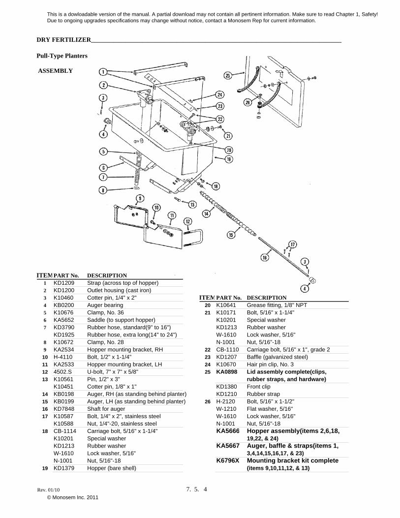
DRY FERTILIZER_______________________________________________________________________________
Pull-Type Planters
ASSEMBLY
ITEMPART No. DESCRIPTION1 KD1209 Strap (across top of hopper)2 KD1200 Outlet housing (cast iron)3 K10460 Cotter pin, 1/4" x 2" ITEMPART No. DESCRIPTION4 KB0200 Auger bearing 20 K10641 Grease fitting, 1/8" NPT5 K10676 Clamp, No. 36 21 K10171 Bolt, 5/16" x 1-1/4"6 KA5652 Saddle (to support hopper) K10201 Special washer7 KD3790 Rubber hose, standard(9" to 16") KD1213 Rubber washer
KD1925 Rubber hose, extra long(14" to 24") W-1610 Lock washer, 5/16"8 K10672 Clamp, No. 28 N-1001 Nut, 5/16"-189 KA2534 Hopper mounting bracket, RH 22 CB-1110 Carriage bolt, 5/16" x 1", grade 2
10 H-4110 Bolt, 1/2" x 1-1/4" 23 KD1207 Baffle (galvanized steel)11 KA2533 Hopper mounting bracket, LH 24 K10670 Hair pin clip, No. 312 4502.S U-bolt, 7" x 7" x 5/8" 25 KA0898 Lid assembly complete(clips, 13 K10561 Pin, 1/2" x 3" rubber straps, and hardware)
K10451 Cotter pin, 1/8" x 1" KD1380 Front clip14 KB0198 Auger, RH (as standing behind planter) KD1210 Rubber strap15 KB0199 Auger, LH (as standing behind planter) 26 H-2120 Bolt, 5/16" x 1-1/2"16 KD7848 Shaft for auger W-1210 Flat washer, 5/16"17 K10587 Bolt, 1/4" x 2", stainless steel W-1610 Lock washer, 5/16"
K10588 Nut, 1/4"-20, stainless steel N-1001 Nut, 5/16"-1818 CB-1114 Carriage bolt, 5/16" x 1-1/4" KA5666 Hopper assembly(items 2,6,18,
K10201 Special washer 19,22, & 24)KD1213 Rubber washer KA5667 Auger, baffle & straps(items 1,W-1610 Lock washer, 5/16" 3,4,14,15,16,17, & 23)N-1001 Nut, 5/16"-18 K6796X Mounting bracket kit complete
19 KD1379 Hopper (bare shell) (items 9,10,11,12, & 13)
Rev. 01/10 7. 5. 4
This is a dowloadable version of the manual. A partial download may not contain all pertinent information. Make sure to read Chapter 1, Safety! Due to ongoing upgrades specifications may change without notice, contact a Monosem Rep for current information.
© Monosem Inc. 2011
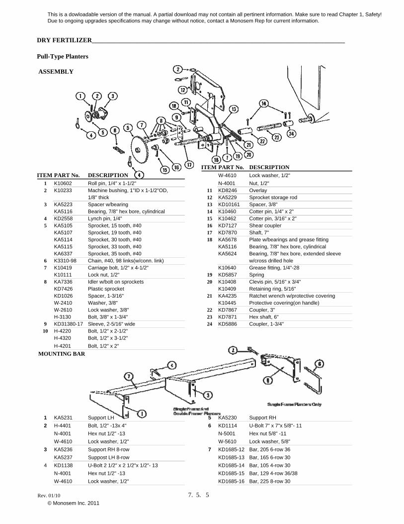
DRY FERTILIZER_______________________________________________________________________________
Pull-Type Planters
ASSEMBLY
ITEM PART No. DESCRIPTIONITEM PART No. DESCRIPTION W-4610 Lock washer, 1/2"
1 K10602 Roll pin, 1/4" x 1-1/2" N-4001 Nut, 1/2"2 K10233 Machine bushing, 1"ID x 1-1/2"OD, 11 KD8246 Overlay
1/8" thick 12 KA5229 Sprocket storage rod3 KA5223 Spacer w/bearing 13 KD10161 Spacer, 3/8"
KA5116 Bearing, 7/8" hex bore, cylindrical 14 K10460 Cotter pin, 1/4" x 2"4 KD2558 Lynch pin, 1/4" 15 K10462 Cotter pin, 3/16" x 2"5 KA5105 Sprocket, 15 tooth, #40 16 KD7127 Shear coupler
KA5107 Sprocket, 19 tooth, #40 17 KD7870 Shaft, 7"KA5114 Sprocket, 30 tooth, #40 18 KA5678 Plate w/bearings and grease fittingKA5115 Sprocket, 33 tooth, #40 KA5116 Bearing, 7/8" hex bore, cylindricalKA6337 Sprocket, 35 tooth, #40 KA5624 Bearing, 7/8" hex bore, extended sleeve
6 K3310-98 Chain, #40, 98 links(w/conn. link) w/cross drilled hole7 K10419 Carriage bolt, 1/2" x 4-1/2" K10640 Grease fitting, 1/4"-28
K10111 Lock nut, 1/2" 19 KD5857 Spring8 KA7336 Idler w/bolt on sprockets 20 K10408 Clevis pin, 5/16" x 3/4"
KD7426 Plastic sprocket K10409 Retaining ring, 5/16"KD1026 Spacer, 1-3/16" 21 KA4235 Ratchet wrench w/protective coveringW-2410 Washer, 3/8" K10445 Protective covering(on handle)W-2610 Lock washer, 3/8" 22 KD7867 Coupler, 3"H-3130 Bolt, 3/8" x 1-3/4" 23 KD7871 Hex shaft, 6"
9 KD31380-17 Sleeve, 2-5/16" wide 24 KD5886 Coupler, 1-3/4"10 H-4220 Bolt, 1/2" x 2-1/2"
H-4320 Bolt, 1/2" x 3-1/2"
H-4201 Bolt, 1/2" x 2"
MOUNTING BAR
1 KA5231 Support LH 5 KA5230 Support RH
2 H-4401 Bolt, 1/2" -13x 4" 6 KD1114 U-Bolt 7" x 7"x 5/8"- 11
N-4001 Hex nut 1/2" -13 N-5001 Hex nut 5/8" -11
W-4610 Lock washer, 1/2" W-5610 Lock washer, 5/8"
3 KA5236 Support RH 8-row 7 KD1685-12 Bar, 205 6-row 36
KA5237 Suppost LH 8-row KD1685-13 Bar, 165 6-row 30
4 KD1138 U-Bolt 2 1/2" x 2 1/2"x 1/2"- 13 KD1685-14 Bar, 105 4-row 30
N-4001 Hex nut 1/2" -13 KD1685-15 Bar, 129 4-row 36/38
W-4610 Lock washer, 1/2" KD1685-16 Bar, 225 8-row 30
Rev. 01/10 7. 5. 5
This is a dowloadable version of the manual. A partial download may not contain all pertinent information. Make sure to read Chapter 1, Safety! Due to ongoing upgrades specifications may change without notice, contact a Monosem Rep for current information.
© Monosem Inc. 2011
DRY FERTILIZER_______________________________________________________________________________
Pull-Type Planters
DOUBLE DISC FERTILIZER OPENER
ITEMPART No. DESCRIPTION1 KA0785 Bracket2 K10451 Cotter pin, 1/8" x 1"3 KD1657 Lockup pin4 KD1657
5 KD0962 Hex head adj. bolt, 5/8" -185 K10499 Jam Nut, 5/8" -186 KA0328 Spring7 KD0487 Bushing ITEMPART No. DESCRIPTION8 K10213 Machine bushing, 11/16" 23 K10133 Hex head cap screw, 5/16" -18 x 1 1/29 K10542 Rivet, 1/4" x 1 5/16" 23 K10109 Lock nut 5/16" -18
10 KD1132 Cap 24 KA0308 Shank11 K10503 Jam Nut, 5/8" -11 RH 25 KA0810 Scraper Mount11 K10504 Jam Nut, 5/8" -11 LH 26 KD1673. Scraper 12 K10204 Machine bushing, 21/32" 27 K10305 Carriage bolt, 3/8" -16x1"13 KB0134 Hub 27 K10210 Washer, 3/8" USS14 KA2014 Bearing 27 K10229 Lock washer, 3/8"15 KD1030 Blade 27 K10101 Hex nut 3/8" -1616 KD2589 Inner Scraper 28 K10045 Hex head cap screw, 1/2" -13x 4 1/2"17 KA0312 Mount 28 K10111 Lock nut 1/2" -1318 K10019 Hex head cap screw, 5/16" - 18 x 1" 29 K10046 Hex head cap screw, 5/8" - 11x5"18 K10232 Lock washer, 5/16" 29 K10107 Lock nut 5/8" -1119 KA1369 Drop Tube 30 KD1339 U-Bolt 2 1/2" x 2 1/2"x 1/2"- 1320 KD1797 Extension 30 K10102 Hex nut 1/2" -13
21 K10681 Clamp, No. 6 30 K10228 Lock washer, 1/2"
22 KA0318 Drop Tube, Liquid FertilizerRev. 12/06 7. 5. 6
This is a dowloadable version of the manual. A partial download may not contain all pertinent information. Make sure to read Chapter 1, Safety! Due to ongoing upgrades specifications may change without notice, contact a Monosem Rep for current information.
© Monosem Inc. 2011
LIQUID FERTILIZER Pull-Type Planters
7. 7. 1
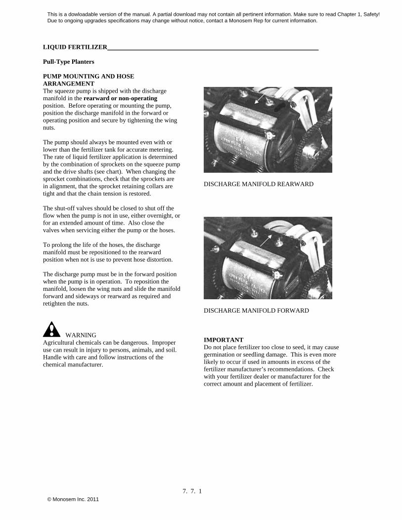
PUMP MOUNTING AND HOSE ARRANGEMENT The squeeze pump is shipped with the discharge manifold in the rearward or non-operating position. Before operating or mounting the pump, position the discharge manifold in the forward or operating position and secure by tightening the wing nuts. The pump should always be mounted even with or lower than the fertilizer tank for accurate metering. The rate of liquid fertilizer application is determined by the combination of sprockets on the squeeze pump and the drive shafts (see chart). When changing the sprocket combinations, check that the sprockets are in alignment, that the sprocket retaining collars are tight and that the chain tension is restored. The shut-off valves should be closed to shut off the flow when the pump is not in use, either overnight, or for an extended amount of time. Also close the valves when servicing either the pump or the hoses. To prolong the life of the hoses, the discharge manifold must be repositioned to the rearward position when not is use to prevent hose distortion. The discharge pump must be in the forward position when the pump is in operation. To reposition the manifold, loosen the wing nuts and slide the manifold forward and sideways or rearward as required and retighten the nuts.
WARNING Agricultural chemicals can be dangerous. Improper use can result in injury to persons, animals, and soil. Handle with care and follow instructions of the chemical manufacturer.
DISCHARGE MANIFOLD REARWARD
DISCHARGE MANIFOLD FORWARD IMPORTANT Do not place fertilizer too close to seed, it may cause germination or seedling damage. This is even more likely to occur if used in amounts in excess of the fertilizer manufacturer’s recommendations. Check with your fertilizer dealer or manufacturer for the correct amount and placement of fertilizer.
This is a dowloadable version of the manual. A partial download may not contain all pertinent information. Make sure to read Chapter 1, Safety! Due to ongoing upgrades specifications may change without notice, contact a Monosem Rep for current information.
© Monosem Inc. 2011
LIQUID FERTILIZER Pull-Type Planters
7. 7. 2
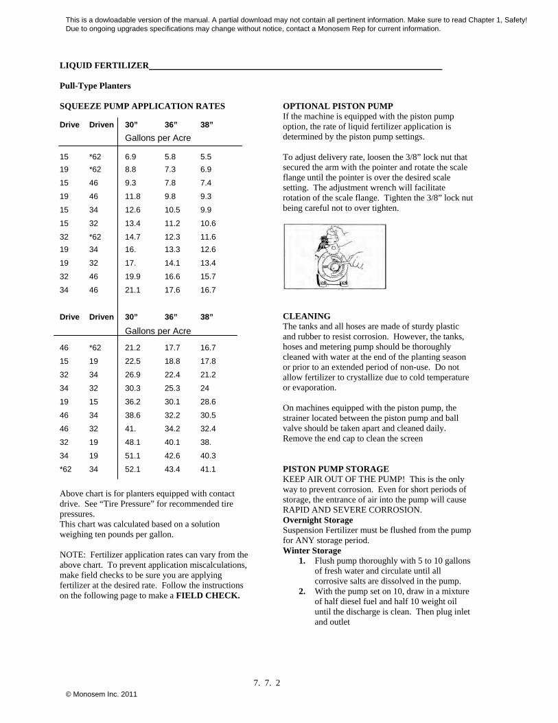
SQUEEZE PUMP APPLICATION RATES
Drive Driven 30” 36” 38”
Gallons per Acre
15 *62 6.9 5.8 5.5
19 *62 8.8 7.3 6.9
15 46 9.3 7.8 7.4
19 46 11.8 9.8 9.3
15 34 12.6 10.5 9.9
15 32 13.4 11.2 10.6
32 *62 14.7 12.3 11.6
19 34 16. 13.3 12.6
19 32 17. 14.1 13.4
32 46 19.9 16.6 15.7
34 46 21.1 17.6 16.7
Drive Driven 30” 36” 38”
Gallons per Acre
46 *62 21.2 17.7 16.7
15 19 22.5 18.8 17.8
32 34 26.9 22.4 21.2
34 32 30.3 25.3 24
19 15 36.2 30.1 28.6
46 34 38.6 32.2 30.5
46 32 41. 34.2 32.4
32 19 48.1 40.1 38.
34 19 51.1 42.6 40.3
*62 34 52.1 43.4 41.1
Above chart is for planters equipped with contact drive. See “Tire Pressure” for recommended tire pressures. This chart was calculated based on a solution weighing ten pounds per gallon. NOTE: Fertilizer application rates can vary from the above chart. To prevent application miscalculations, make field checks to be sure you are applying fertilizer at the desired rate. Follow the instructions on the following page to make a FIELD CHECK.
OPTIONAL PISTON PUMP If the machine is equipped with the piston pump option, the rate of liquid fertilizer application is determined by the piston pump settings. To adjust delivery rate, loosen the 3/8” lock nut that secured the arm with the pointer and rotate the scale flange until the pointer is over the desired scale setting. The adjustment wrench will facilitate rotation of the scale flange. Tighten the 3/8” lock nut being careful not to over tighten.
CLEANING The tanks and all hoses are made of sturdy plastic and rubber to resist corrosion. However, the tanks, hoses and metering pump should be thoroughly cleaned with water at the end of the planting season or prior to an extended period of non-use. Do not allow fertilizer to crystallize due to cold temperature or evaporation. On machines equipped with the piston pump, the strainer located between the piston pump and ball valve should be taken apart and cleaned daily. Remove the end cap to clean the screen PISTON PUMP STORAGE KEEP AIR OUT OF THE PUMP! This is the only way to prevent corrosion. Even for short periods of storage, the entrance of air into the pump will cause RAPID AND SEVERE CORROSION. Overnight Storage Suspension Fertilizer must be flushed from the pump for ANY storage period. Winter Storage
1. Flush pump thoroughly with 5 to 10 gallons of fresh water and circulate until all corrosive salts are dissolved in the pump.
2. With the pump set on 10, draw in a mixture of half diesel fuel and half 10 weight oil until the discharge is clean. Then plug inlet and outlet
This is a dowloadable version of the manual. A partial download may not contain all pertinent information. Make sure to read Chapter 1, Safety! Due to ongoing upgrades specifications may change without notice, contact a Monosem Rep for current information.
© Monosem Inc. 2011
LIQUID FERTILIZER Pull-Type Planters
7. 7. 3
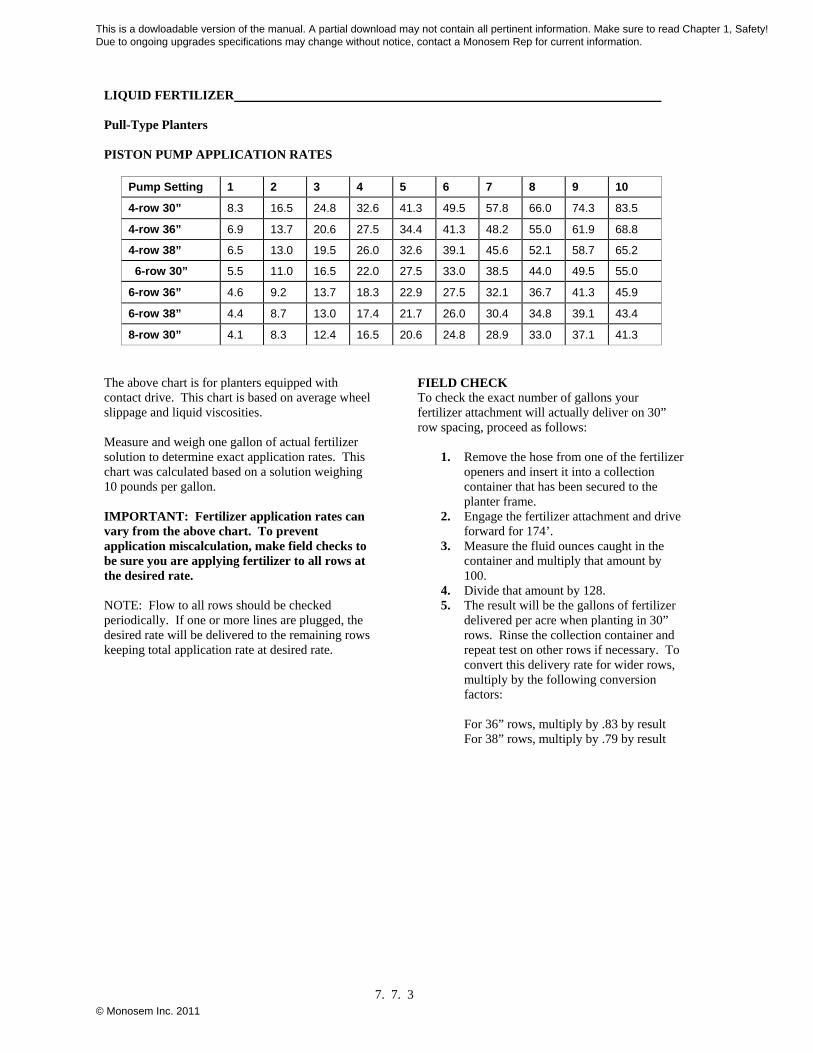
PISTON PUMP APPLICATION RATES
Pump Setting 1 2 3 4 5 6 7 8 9 10
4-row 30” 8.3 16.5 24.8 32.6 41.3 49.5 57.8 66.0 74.3 83.5
4-row 36” 6.9 13.7 20.6 27.5 34.4 41.3 48.2 55.0 61.9 68.8
4-row 38” 6.5 13.0 19.5 26.0 32.6 39.1 45.6 52.1 58.7 65.2
6-row 30” 5.5 11.0 16.5 22.0 27.5 33.0 38.5 44.0 49.5 55.0
6-row 36” 4.6 9.2 13.7 18.3 22.9 27.5 32.1 36.7 41.3 45.9
6-row 38” 4.4 8.7 13.0 17.4 21.7 26.0 30.4 34.8 39.1 43.4
8-row 30” 4.1 8.3 12.4 16.5 20.6 24.8 28.9 33.0 37.1 41.3
The above chart is for planters equipped with contact drive. This chart is based on average wheel slippage and liquid viscosities. Measure and weigh one gallon of actual fertilizer solution to determine exact application rates. This chart was calculated based on a solution weighing 10 pounds per gallon. IMPORTANT: Fertilizer application rates can vary from the above chart. To prevent application miscalculation, make field checks to be sure you are applying fertilizer to all rows at the desired rate. NOTE: Flow to all rows should be checked periodically. If one or more lines are plugged, the desired rate will be delivered to the remaining rows keeping total application rate at desired rate.
FIELD CHECK To check the exact number of gallons your fertilizer attachment will actually deliver on 30” row spacing, proceed as follows:
1. Remove the hose from one of the fertilizer openers and insert it into a collection container that has been secured to the planter frame.
2. Engage the fertilizer attachment and drive forward for 174’.
3. Measure the fluid ounces caught in the container and multiply that amount by 100.
4. Divide that amount by 128. 5. The result will be the gallons of fertilizer
delivered per acre when planting in 30” rows. Rinse the collection container and repeat test on other rows if necessary. To convert this delivery rate for wider rows, multiply by the following conversion factors:
For 36” rows, multiply by .83 by result For 38” rows, multiply by .79 by result
This is a dowloadable version of the manual. A partial download may not contain all pertinent information. Make sure to read Chapter 1, Safety! Due to ongoing upgrades specifications may change without notice, contact a Monosem Rep for current information.
© Monosem Inc. 2011
LIQUID FERTILIZER Pull-Type Planters
7. 7. 4
TROUBLE SHOOTING PROBLEM: Pump Hard or impossible to Prime.
POSSIBLE CAUSE: Valves fouled or in wrong place. Inspect and clean valves. Air leak in suction line Repair Leak Pump is set too low Adjust Pump Setting Packing washers are worn out Replace.
PROBLEM: Low Metering.
POSSIBLE CAUSE: Valves fouled or in wrong place. Inspect and clean valves. Air leak in suction line Repair Leak Pump is set too low Adjust Pump Setting Broken valve spring Replace.
PROBLEM: Over Metering.
POSSIBLE CAUSE: Improper rate setting Adjust Pump Setting Trash is under valves Inspect and clean valves Broken discharge valve spring Replace.
PROBLEM: Leaks Through when Stopped.
POSSIBLE CAUSE: Trash is under valves Inspect and clean valves Broken discharge valve spring Replace.
PROBLEM: Fertilizer Solution leaking under stuffing box
POSSIBLE CAUSE: Packing washers are worn out Replace.
PROBLEM: Pump is using excessive Oil
POSSIBLE CAUSE: Oil seals or o-ring worn and leaking Replace.
PROBLEM: Pump operates noisily POSSIBLE CAUSE:
Crankcase components worn excessively Inspect and replace if necessary.
This is a dowloadable version of the manual. A partial download may not contain all pertinent information. Make sure to read Chapter 1, Safety! Due to ongoing upgrades specifications may change without notice, contact a Monosem Rep for current information.
© Monosem Inc. 2011

LIQUID FERTILIZER___________________________________________________________________________
Pull-Type Frame
SQUEEZE PUMP ASSEMBLY
Revised: 08/06 7. 7. 5
This is a dowloadable version of the manual. A partial download may not contain all pertinent information. Make sure to read Chapter 1, Safety! Due to ongoing upgrades specifications may change without notice, contact a Monosem Rep for current information.
© Monosem Inc. 2011

LIQUID FERTILIZER___________________________________________________________________________
Pull-Type Frame
SQUEEZE PUMP ASSEMBLY
ITEM PART No. DESCRIPTION ITEM PART No. DESCRIPTION1 JBL6C SQUEEZE PUMP 2 - 6 ROWS 18 K10017 HEX BOLT, 1/2-13 X 1 1/2"
JBL8LC SQUEEZE PUMP 8 ROWS K10228 LOCK WASHER, 1/2"
JBL12C SQUEEZE PUMP 12 ROWS K10102 HEX NUT, 1/2-13
2 MPL1414 7/8" SPROCKET ADAPTER 19 KD5857 SPRING
3 F64286 SPRING PIN 5/16 X 2-1/4" 20 KD5988 SHAFT, 36" (4 & 6 ROW)
4 MPL1381 SPROCKET, 20 TOOTH KD5990 SHAFT, 74" ( 8 ROW)
MPL1383 SPROCKET, 8 TOOTH 21 KD3839 COUPLER, 2"
MPL1384 SPROCKET, 9 TOOTH 22 K10460 COTTER PIN, 1/4" X 2"
MPL1385 SPROCKET, 10 TOOTH 23 K10602 SPRING PIN, 1/4" X 1 1/2"
MPL1386 SPROCKET, 15 TOOTH 24 KD14431 HANDLE
MPL1387 SPROCKET, 22 TOOTH 25 KD14413 TORSION SPRING, L.H.
MPL1388 SPROCKET, 23 TOOTH 26 KD14430 RELEASE COLLAR, GOLD, R.H.
MPL1389 SPROCKET, 26 TOOTH 27 KA5229 SPROCKET STORAGE ROD
5 MPL4414 7/8" SPROCKET RETAINER 28 KD6165 PLATE, 8 ROW PUMP
6 KD2558 LYNCH PIN, 1/4" 29 K10004 HEX BOLT, 3/8-16 X 1 1/4"
7 KD2734-08 SLEEVE, 1 1/4" X 5/8" K10210 WASHER, 3/8" USS
8 KA7336 IDLER W/SPROCKETS K10229 LOCK WASHER, 3/8"
KD7426 SPROCKET, 12 TOOTH K10101 HEX NUT, 3/8-16
KD1026 SLEEVE, 1 3/16" 30 K11078 COVER
K10210 WASHER, 3/8" USS 31 KD14432 SLEEVE, 1 1/4"
K10229 LOCK WASHER, 3/8" 32 K11075 SNAP RING, 7/8"
K10047 HEX BOLT, 3/8-16 X 1 3/4" 33 K10496 SNAP RING, 1 1/2"
9 K11100 SCREW, 1/2-20 X 1/2" 34 KD14427 SHAFT, 4 7/8"
K10227 LOCK WASHER, 1/4"
K10209 WASHER, 1/4" USS K1K378 WRENCH REPLACEMENT KIT
10 G169A2040 CHAIN, #A2040 (#7, 9, 24-26, and 32-36)
G171A2040 CONNECTOR LINK, #A2040
G172A2040 OFFSET LINK, #A2040
11 KA2354 ADAPTER
12 KA2355 LOCK COLLAR
13 K3400-01 FLANGETTE
14 K2100-03 BEARING
15 K10303 CARRIAGE BOLT 5/16-18 X 1
K10232 LOCK WASHER 5/16"
K10106 HEX NUT 5/16-18
16 K4200 FERTILIZER HOSE 1 1/4"
HC-024 HOSE CLAMP
17 KD15685 CLAMP
Revised: 08/06 7. 7. 6
This is a dowloadable version of the manual. A partial download may not contain all pertinent information. Make sure to read Chapter 1, Safety! Due to ongoing upgrades specifications may change without notice, contact a Monosem Rep for current information.
© Monosem Inc. 2011