Embed Size (px)
Citation preview

1
Vibraciones en pisos de
edificaciones con estructura
de al uso humano
Presented by
Thomas M. Murray, Ph.D., P.E.
Department of Civil and Environmental Engineering
Virginia Tech, Blacksburg, Virginia
26 October 2011

2 2 2 2
Floor Vibrations
A Critical Serviceability
Consideration
for Steel Framed Floors.
Humans are very sensitive to vertical
floor motion.

3 3 3 3
Topics
Basic Vibration Terminology
Floor Vibration Fundamentals
Walking Vibrations
Rhythmic Vibrations
Footbridges
Retrofitting
4
BASIC VIBRATION
TERMINOLOGY

5 5 5 5
Period And Frequency
Period t p

6 6 6 6
Natural Frequency
wL
tIsgE
2f
2/1
4n

7 7 7 7
Damping
Loss of Mechanical Energy in a Vibrating System
Critical Damping
Smallest Amount of Viscous Damping
Required to Prevent Oscillation of a
Free Vibrating System

8
Harmonics
P3
1st Harmonic
2nd Harmonic
3rd Harmonic
Footstep = tficosPstepi 2
f1f step1
f2f step2
f3f step3
P1
P2
0 0.2 0.4 0.6 0.80
0.05
0.1
0.15
0.2
0.25
0.3
Time (sec.)
Gro
und R
eaction (
kip
)

9 9 9 9
Acceleration Ratio
Acceleration Of A System, ap
Acceleration Of Gravity, ag
Usually Expressed As %g.
0.5%g is the Human Tolerance
Level for Quite Environments.
Ratio =

10 10 10 10
Effective Weight Floor Width
Flo
or
Le
ng
th
W

11
FLOOR VIBRATION
FUNDAMENTALS

12
The Power of Resonance
0 1 2
Flo
or
Resp
on
se
2 - 3% Damping
Natural frequency, fn
Forcing frequency, f
5 - 7% Damping

13 13 13 13
Phenomenon of Resonance
• Resonance can also occur when a
multiple of the forcing function
frequency equals a natural frequency of
the floor.
• Usually concerned with the first natural
frequency.
• Resonance can occur because of walking
dancing, or exercising.

14 14 14 14
0 1 2 3 4 5 6 70
0.1
0.2
0.3
0.4
0.5
Frequency (Hz)
Measure
d A
uto
spectr
um
(P
eak,
%g)
Walking
Speed
100 bpm
2nd Harmonic
3.33 Hz
System Frequency
5 Hz – 3rd Harmonic
Response from a Lightly
Damped Floor

15 15 15 15
A Tolerance Criterion has two parts:
• Prediction of the floor response to a
specified excitation.
• Human response/tolerance
Human Tolerance Criterion

16 16 16 16
FloorVibe v2.02 Software for Analyzing
Floors for Vibrations
Criteria Based on AISC/CISC Design
Guide 11
SEI
Structural Engineers, Inc.
537 Wisteria Drive
Radford, VA 24141
540-731-3330 Fax 540-639-0713
http://www.floorvibe.com
AISC/CISC Design Guide

17 17 17 17
_ _ _ _
_ _ _ _
_ _ _ _
_ ___ _
1 3 4 5 8 10 25 40
25
10
5
2.5
1
0.5
0.25
0.1
0.05
Rhythmic Activities
Outdoor Footbridges
Shopping Malls,
Dining and Dancing
Offices,
Residences
ISO Baseline Curve for
RMS Acceleration
Pea
k A
ccel
era
tio
n (
% G
ravit
y)
Frequency (Hz)
Indoor Footbridges,
. . . . . . . . . . . . . . . . . . . . . . . .
. . . . . . . . . . . . . . . . . . . . . . . .
. . . . . . . . . . . . . . . . . . . . . . . .
DG11 Uses
the Modified
ISO Scale for
Human
Tolerance

18
NATURAL FREQUENCY
OF
STEEL FRAMED
FLOOR SYSTEMS
19 19 19 19
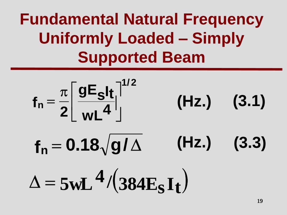
Fundamental Natural Frequency
Uniformly Loaded – Simply
Supported Beam
(3.3)
(3.1)
(Hz.)
wL4
ItgEs2
f
2/1
n (Hz.)
/g18.0fn
ItE384 s/wL5 4

20 20 20 20
Member
Bay
System
Fundamental Frequencies
H/g18.0f zn
)/(g18.0f gbn
)/(g18.0f cgbn
21 21 21 21
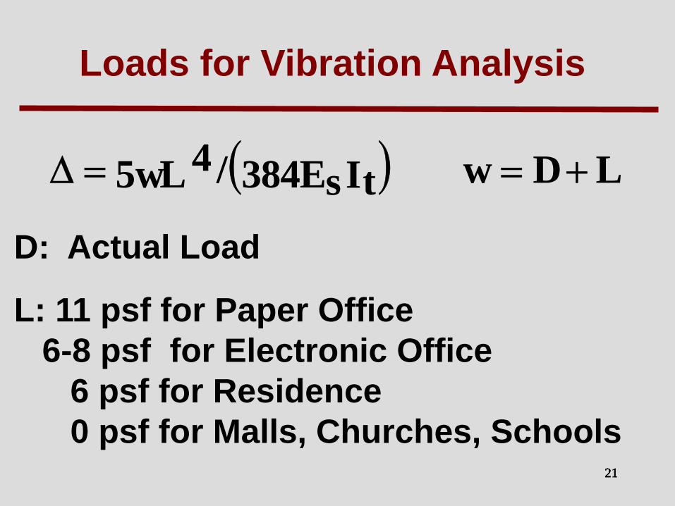
Loads for Vibration Analysis
LDwItE384 s/wL5 4
D: Actual Load
L: 11 psf for Paper Office
6-8 psf for Electronic Office
6 psf for Residence
0 psf for Malls, Churches, Schools

22 22 22 22
Section Properties - Beam/Girder
b (< 0.4 L)
• Fully Composite
• Effect Width
• n = Es/1.35Ec

23
Why is the full composite moment of inertia used in the frequency calculations even when the beam or girder is non-composite?
)/(g18.0f gbn
ItE384 s/wL5 4
A Frequently Asked Question

24
Why is the full composite moment of inertia used in the frequency calculations even when the beam or girder is non-composite?
Annoying vibrations have displacements
of 1-3 mm. Thus, the interface shear is
negligible, so its acts as fully composite.
A Frequently Asked Question

25 25 25 25
Minimum Frequency
To avoid resonance with the first
harmonic of walking, the
minimum frequency must be
greater than 3 Hz. e.g.
fn > 3 Hz

26
DESIGN FOR
WALKING EXCITATION

27 27 27 27
Walking Vibrations Criterion
g
a
W
)f35.0exp(P
g
a onop
Predicted Tolerance

28 28 28 28
ap = peak acceleration
ao = acceleration limit
g = acceleration of gravity
fn = fundamental frequency of a beam or joist panel, or a combined panel, as applicable
Po = a constant force equal to 65 lb for floors and 92 lb for footbridges
= modal damping ratio (0.01 to 0.05 or 1% to 5%)
W = effective weight supported by the beam or joist panel, girder panel, or combined panel, as applicable
g
a
W
)f35.0exp(P
g
a onop
Walking Vibrations Criterion

29 29 29 29
_ _ _ _
_ _ _ _
_ _ _ _
_ _ __ _
1 3 4 5 8 10 25 40
25
10
5
2.5
1
0.5
0.25
0.1
0.05
Rhythmic Activities
Outdoor Footbridges
Shopping Malls,
Dining and Dancing
Offices,
Residences
Pea
k A
ccel
era
tio
n (
% G
ravit
y)
Frequency (Hz)
Indoor Footbridges,
. . . . . . . . . . . . . . . . . . . . . . . .
. . . . . . . . . . . . . . . . . . . . . . .
. . . . . . . . . . . . . . . . . . . . . . . .
ISO Baseline Curve for
RMS Acceleration
Modified
ISO Scale

30 30 30 30
Recommended Values of Parameters in Equation (4.1) and a /g Limits o
Occupancy Constant Force Damping Ratio Acceleration Limit
ao/g x 100% Po
Offices, Residences, 65 lb (0.29 kN) 0.02 – 0.05
* 0.5% Churches
Shopping Malls 0.02 1.5%
Footbridges - Indoor 0.01 1.5%
Footbridges - Outdoor 0.01 5.0%
Table 4.1
* 0.02 for floors w ith few non-structural components (ceilings, ducts, partitions,
etc.) as can occur in open w ork areas and churches,
0.03 for floors w ith non-structural components and furnishings, but w ith only
small demountable partitions typical of many modular office areas,
0.05 for full height partitions betw een floors.
Parameters
65 lb (0.29 kN)
92 lb (0.41 kN)
92 lb (0.41 kN)

31
Estimating Modal Damping, β
Structural System – 0.01 (1%)
Ceiling and Ductwork – 0.01(1%)
Electronic Office Fitout – 0.005 (0.5%)
Paper Office Fitout – 0.01 (1%)
Churches, Schools, Malls – 0%
Dry Wall Partitions in Bay – 0.05 to 0.10
5% to 10%
Note: Damping is cumulative.

32 32 32 32
Use very low live load (6-8 psf or
0.27-0.35 kPa) and low modal
damping (2% – 2.5%) for electronic
office floor systems.
See Floor Vibration and the
Electronic Office in Modern Steel
Construction August 1998
Important

33 33 33 33
Equivalent Combined Mode
Panel Weight (W in Eqn. 2.3)
(4.4)
g
a
W
)f35.0exp(P
g
a onop
WWW g
gj
gj
gj
j

34 34 34 34
Beam and Girder Panel
Effective Weights
Beam Panel:
Girder Panel:
LjBj)S/wj(=Wj
LgBg)L avg,j/wg(=Wg
35 35 35 35
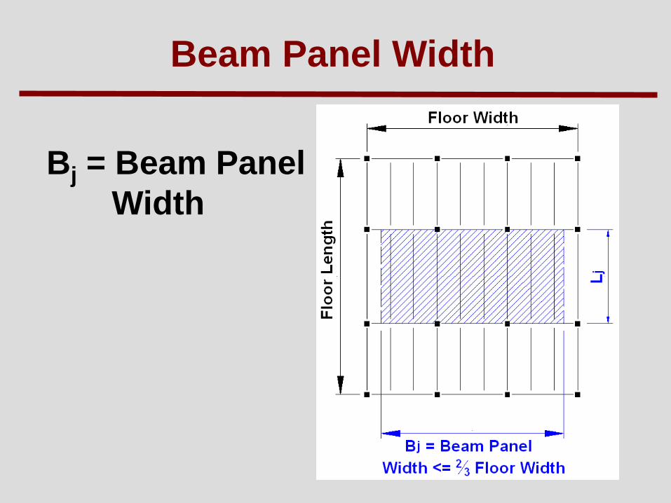
Beam Panel Width
Bj = Beam Panel
Width

36 36 36 36
Effective Beam Panel Width
× Floor Width
Cj = 2.0 For Beams In Most Areas
= 1.0 For Beams at a Free Edge
(Balcony)
Dj = Ij/S (in4/ft)
3/2L)Dj/Ds(CjB j
4/1
j

37 37 37 37
Section Properties - Slab
12” ´
_ _ _ _
de=dc-ddeck /2
A = (12 / n) de
n = Es/1.35 Ec
in4/ ft
f’c in ksi
)12/d)(n/12(D3es
fwE c5.1
c

38 38 38 38
Beam or Joist Panel
Effective Weights
For hot-rolled beams or joists
with extended bottom chords, Wj
can increased 50% if an adjacent
span is greater than 0.7 x the span
considered. That is,
Wj = 1.5(wj/S)BjLj

39 39 39 39
Effective Girder Panel Width
Bg = Girder
Panel
Width

40 40 40 40
Effective Girder Panel Width
Bg = Cg(Dj/Dg)1/4 Lg 2/3 × Floor Length
Cg = 1.6 For Girders Supporting Joists
Connected Only to a Girder Flange
= 1.8 For Girders Supporting Beams
Connected to a Girder Web
Dg = Ig/Lj,avg in4/ft
41 41 41 41
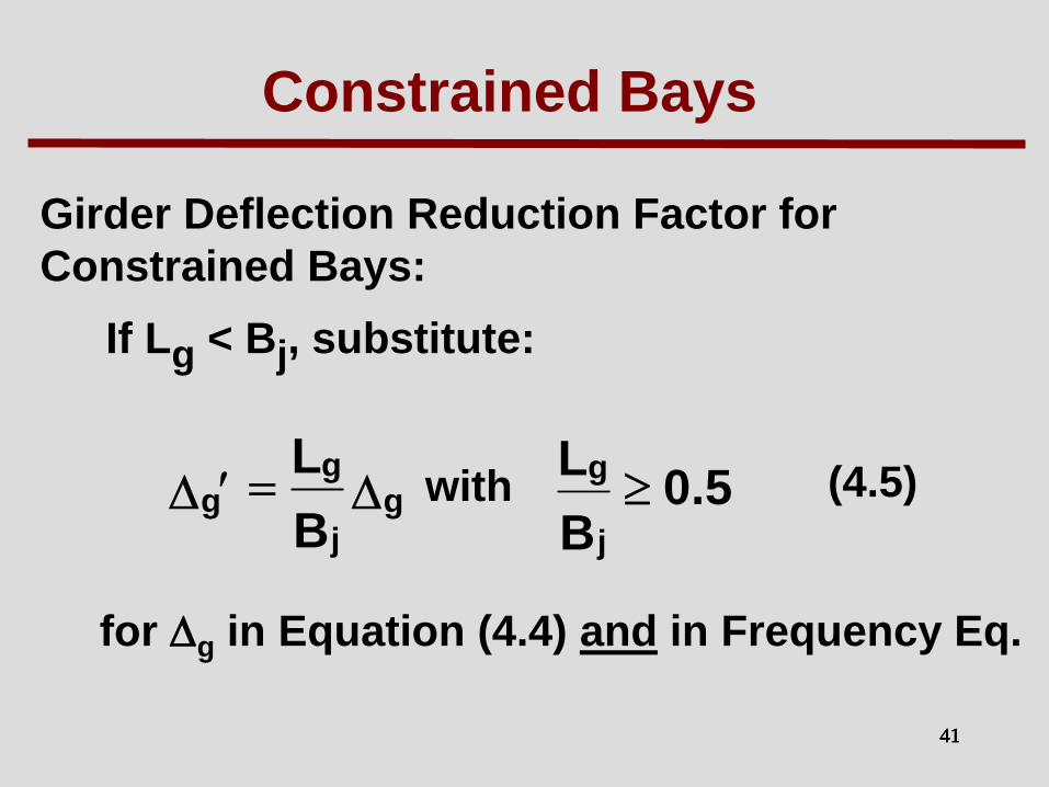
Constrained Bays
Girder Deflection Reduction Factor for
Constrained Bays:
If Lg < Bj, substitute:
(4.5)
for g in Equation (4.4) and in Frequency Eq.
g
j
gg
B
L5.0
B
L
j
gwith

42 42 42
Example

43 43 43 43
S
W24 × 55
W21 × 44 4 SPA @ 7´- 6´ =30´= L ´ g
W2
1 ×
44
W
14
× 2
2
W1
8 ×
35
W1
4 ×
22
L =
45
´ j
W18 × 35
3.50”
2.00”
d = 3.50 + e
2.00
2 = 4.50”
Section W1
4 ×
22
Floor Width = 30 ft
Floor Length = 90 ft
Paper Office

44 44 44 44
Gravity Loads: LL : 11 psf (0.5 kPa) (For Vibration Analysis)
Mech. & Ceiling : 4 psf (0.2 kPa)
Deck Properties: Concrete: wc = 110 pcf f’c = 4000 psi
Floor Thickness = 3.50 in. + 2 in. ribs
= 5.50 in.
Slab + Deck Weight = 47 psf
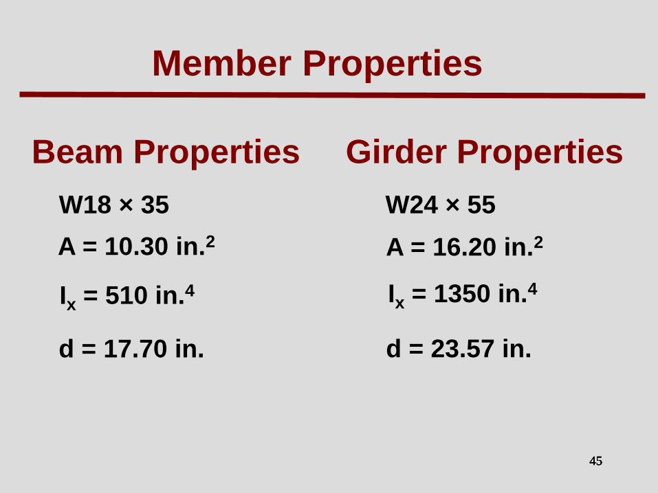
45 45 45 45
Beam Properties
W18 × 35
A = 10.30 in.2
Ix = 510 in.4
d = 17.70 in.
Girder Properties
W24 × 55
A = 16.20 in.2
d = 23.57 in.
Member Properties
Ix = 1350 in.4

46 46 46 46
Beam Mode Properties
Effective Concrete Slab Width = 7.5 ft < 0.4 Lj
= 0.4 x 45 = 18 ft.
n = modular ratio = Es/1.35Ec
= 29000 / (1.35 x 2307)
= 9.31
Ij = transformed moment of inertia = 1799 in4
ksi23070.4110fwE5.1
c5.1
c
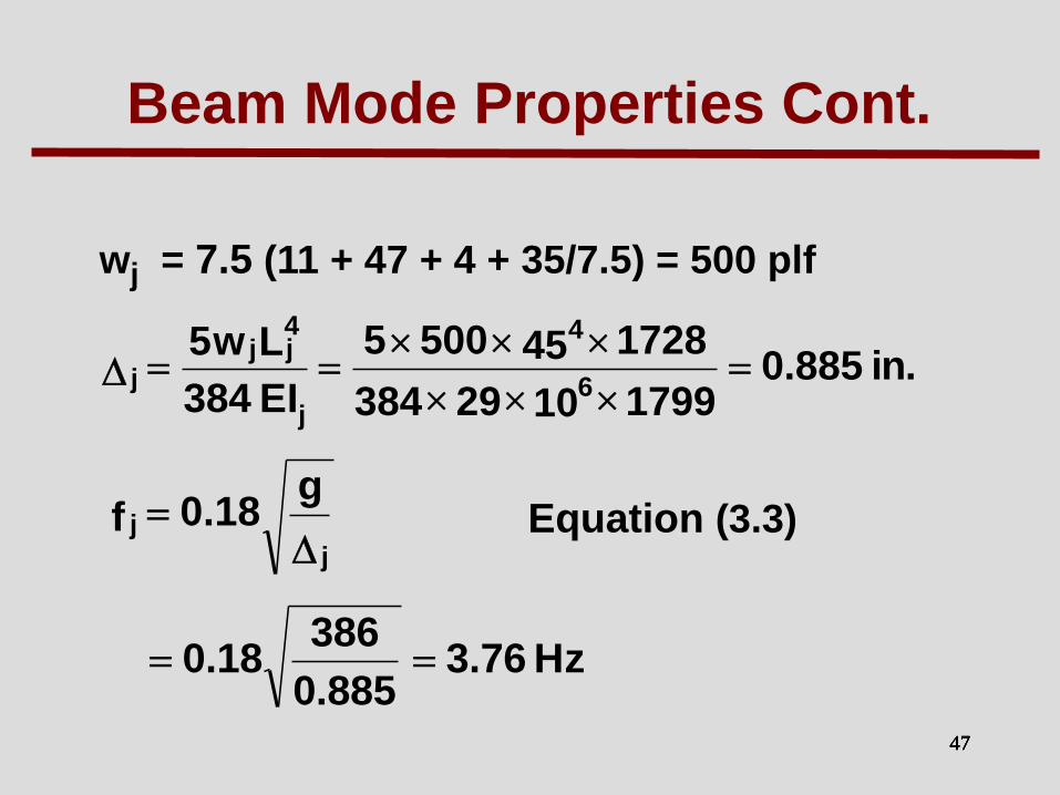
47 47 47 47
wj = 7.5 (11 + 47 + 4 + 35/7.5) = 500 plf
Equation (3.3)
Beam Mode Properties Cont.
.in885.017991029384
1728455005
EI384
Lw56
4
j
4jj
j
j
j
g18.0f
Hz76.3885.0
38618.0

48 48 48 48
Cj = 2.0
Bj = Cj (Ds/ Dj)1/4Lj
= 2.0 (9.79 / 240)1/4(45) = 40.4 ft > 2/3 (30) = 20 ft.
Wj = 1.5(wj/S)BjLj (50% Increase)
= 1.5 (500/7.5)(20.0 × 45) = 90,000 lbs = 90.0 kips
Beam Mode Properties Cont.
Bj = 20 ft.
.ft/.in240 4=5.7/1799=S/Ij=Dj
ft/.in79.9 4=)12/50.4 3)(31.9/12(=)12/d( 3e)n/12(=Ds

49 49 49 49
Girder Mode Properties
Eff. Slab Width = 0.4 Lg
= 0.4 x 30 x 12
= 144 in. < Lj = 45 x 12 = 540 in.
b = 144”
Ig = 4436 in4
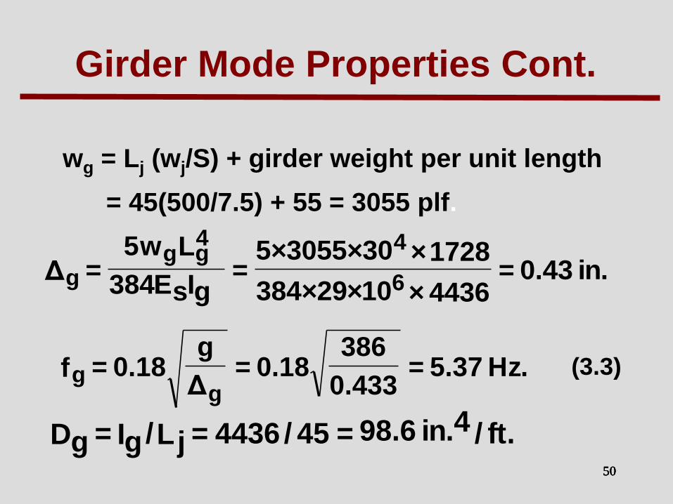
50 50 50 50
wg = Lj (wj/S) + girder weight per unit length
= 45(500/7.5) + 55 = 3055 plf.
(3.3)
Girder Mode Properties Cont.
.in43.0=4436×10×29×384
1728×30×3055×5=
gIsE384
Lw5=Δ 6
44gg
g
.Hz37.5=433.0
38618.0=
Δ
g18.0=f
gg
.ft/.in6.98 4=45/4436=Lj/Ig=Dg

51 51 51 51
Cg = 1.8 (Beam Connected To Girder Web)
(4.3b)
= 1.8 (240 / 98.6)1/4 (30) = 67.4 ft > 2/3 (90) = 60
(4.2)
=(3055/45)(60 × 30) = 122,200 lb = 122 kips
Use
Girder Mode Properties Cont.
L)Dg/Dj(CgB g
4/1
g
LB)L/w(W ggjgg

52 52 52 52
Combined Mode Properties
Lg = 30 ft < Bj = 20 ft Do Not Reduce
fn = Fundamental Floor Frequency
)+18.0= ΔΔ/(g gj
Hz08.3=
)433.0+885.0/(38618.0=

53 53 53 53
Combined Mode Properties Cont.
WΔΔ
ΔW
ΔΔ
Δg
gj
gj
gj
j
++
+=W
kips100=
)122(433.0+885.0
433.0+)90(
433.0+885.0
885.0=

54 54 54 54
= 0.0074
= 0.03 from Table 4.1 (Modal Damping Ratio)
W = 0.03 × 100 = 3.0 kips
Evaluation
= 0.74% g > 0.50% g N.G.
3000
)08.335.0exp(65
W
)f35.0exp(P
g
a nop

55 55 55 55
_ _ _ _
_ _ _ _
_ _ _ _
_ _ __ _
1 3 4 5 8 10 25 40
25
10
5
2.5
1
0.5
0.25
0.1
0.05
Rhythmic Activities
Outdoor Footbridges
Shopping Malls,
Dining and Dancing
Offices,
Residences
Pea
k A
ccel
era
tio
n (
% G
ravit
y)
Frequency (Hz)
Indoor Footbridges,
Extended by Allen
and Murray (1993) . . . . . . . . . . . . . . . . . . . . . . . .
. . . . . . . . . . . . . . . . . . . . . . .
. . . . . . . . . . . . . . . . . . . . . . . .
ISO Baseline Curve for
RMS Acceleration
56 56 56 56
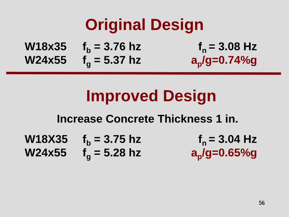
Original Design
W18x35 fb = 3.76 hz fn = 3.08 Hz
W24x55 fg = 5.37 hz ap/g=0.74%g
Improved Design
Increase Concrete Thickness 1 in.
W18X35 fb = 3.75 hz fn = 3.04 Hz
W24x55 fg = 5.28 hz ap/g=0.65%g

57 57 57 57
Original Design
W18x35 fb = 3.76 hz fn = 3.08 Hz
W24x55 fg = 5.37 hz ap/g=0.74%g
Improved Design
Increase Girder Size
W18X35 fb = 3.76 hz fn = 3.33 Hz
W24x84 fg = 7.17 hz ap/g=0.70%g

58 58 58 58
W18x35 fb = 3.76 hz fn = 3.08 Hz
W24x55 fg = 5.37 hz ap/g=0.74%g
Improved Designs
Increase Beam Size
W21x50 fb = 4.84 hz fn = 3.57 Hz
W24x55 fg = 5.29 hz ap/g=0.58%g
W24x55 fb = 5.22 hz fn = 3.71 Hz
W24x55 fg = 5.28 hz ap/g=0.50%g
Original Design

59 59 59 59
Rule: In design, increase stiffness
of element with lower
frequency to improve
performance.
If beam frequency is less than the girder frequency, increase the beam frequency to the girder frequency first, then increase both until a satisfactory design is obtained.

60 60 60
DG11 Floor Width and Length

61 61 61 61
Bay Floor
Width
Floor
Length
A
B
C
D
Floor Width and
Length Example
A
B
D
C

62 62 62 62
Bay Floor
Width
Floor
Length
A 90 90
B
C
D
Floor Width and
Length Example
A
B
D
C

63 63 63 63
Bay Floor
Width
Floor
Length
A 90 90
B 150 90
C
D
Floor Width and
Length Example
A
B
D
C

64 64 64 64
Bay Floor
Width
Floor
Length
A 90 90
B 150 90
C 150 30 (45?)
D
Floor Width and
Length Example
A
B
D
C
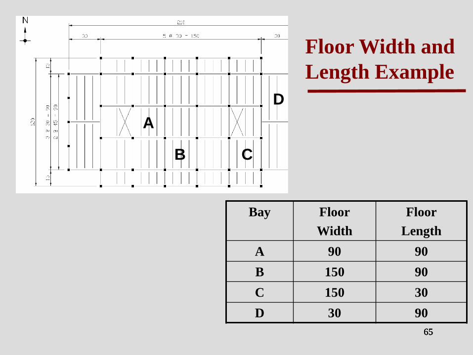
65 65 65 65
Bay Floor
Width
Floor
Length
A 90 90
B 150 90
C 150 30
D 30 90
Floor Width and
Length Example
A
B
D
C

66
Bg = Cg(Dj/Dg)1/4 Lg 2/3 × Floor Length

67
Bg = Cg(Dj/Dg)1/4 Lg 2/3 × Floor Length
Bays A & B
Bg = 59.9’<2/3Floor
Length

68
Bg = Cg(Dj/Dg)1/4 Lg 2/3 × Floor Length
Bays A & B
Bg = 59.9’<2/3 Floor L
Bays A:
Floor Length = 81’
e.g. (32.5’ + 16” + 32.5’)
Bg=2/3x81 = 54’ < 59.9’
ap/g=0.46%g < 0.5%

69
Bg = Cg(Dj/Dg)1/4 Lg 2/3 × Floor Length
Bays A & B
Bg = 59.9’< 2/3Floor L
Bays A: Bg = 54’
ap/g=0.46%g < 0.5%
OK
Bay B:
Floor Length = 48.5’
e.g. (32.5’ + 16’)
2/3x48.5 =32.3’ < 59.9’
ap/g=0.61%g > 0.5%g
NG

70
DESIGN FOR
RHYTHMIC EXCITATION

71 71 71 71
Aerobics

72 72 72 72
Balcony Video

73 73 73 73
b, g and c are beam, girder and column
deflections due to supported weight
Natural Frequency for
Rhythmic Excitation
Column deflections may be important for
aerobic excitations.
)/(g18.0f cgbn
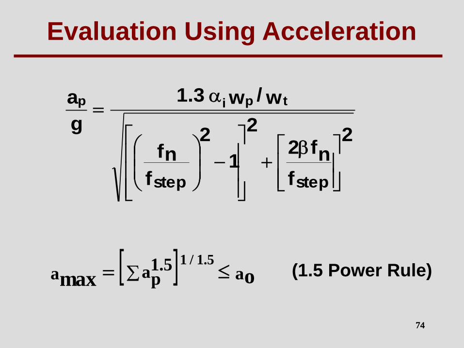
74 74 74 74
f
f2 n2
1f
fn2
2
w/w3.1
g
a
stepstep
tpip
aa 5.1pa omax
5.1/1 (1.5 Power Rule)
Evaluation Using Acceleration

75 75 75
g18.0nf
Note, for a given fn, Δ is constant.
Example. For fn = 5 Hz, g = 386 in/sec2
Δ = 0.5 in regardless of span length!!
Frequency versus Span

76
FOOTBRIDGES

77 77 77 77
Be careful when designing foot-
bridges and crossovers
• Very low damping
• Low frequency
• Lateral Vibrations

78 78 78 78
Troubled Bridge
Over Water

79
VIDEO

80
VIDEO

81
EVALUATION AND
REMEDIAL MEASURES
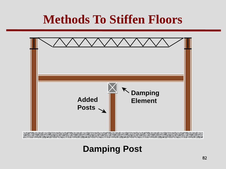
82 82 82 82
Methods To Stiffen Floors
Damping Post
Added
Posts
Damping
Element

83 83 83 83
Methods To Stiffen Floors
Steel Rod Cover Plate
Cover Plates and Bottom Chord Reinforcing
Generally do not Work

84 84 84 84
Queen Post Hanger Stiffening
HVAC
Added Queen Post Hanger

85 85 85 85
Queen Post Hanger Stiffening

86 86 86 86
Queen Post Hanger Stiffening

87 87 87 87
Stiffening Of Girders Supporting
Cantilevered Beams and Joist Seats
Cantilevered
Beam or
Joist Seat
Girder
Stiffener

88 88 88 88
Pendulum TMD
Large Mass ~ 2% Mass Ratio “Frictionless” Bearings
Coil Spring
Air Dashpot Damping

89 89 89 89
Pendulum TMD

90 90 90 90
5th Floor - Response to Walking
-0.006
-0.004
-0.002
0.000
0.002
0.004
0.006
10.0 12.0 14.0 16.0 18.0 20.0 22.0 24.0
Time, seconds
Accele
rati
on
, g
's
Floor Acceleration w /o TMD
5th Floor - Response to Walking
-0.006
-0.004
-0.002
0.000
0.002
0.004
0.006
10.0 12.0 14.0 16.0 18.0 20.0 22.0 24.0
Time, seconds
Accele
rati
on
, g
's
Floor Acceleration w ith TMD
Without TMD
With TMD
Walking

91 91 91 91
Response to Walking
Results
5th Floor Response to Walking
0.000
0.002
0.004
0.006
0.008
0.010
0.012
0.014
0.016
0 1 2 3 4 5 6 7 8 9 10
Frequency, Hz.
Ve
locity, in
/se
c 0
-pk
Floor Velocity w/o TMD
Floor Velocity with TMD
5.25 Hz. , 0.01523 ips 0-pk
5.25 Hz. , 0.00756 ips 0-pk
50% Reduction

92

93 93 93
Final Thought
Strength is essential but otherwise
unimportant.
Hardy Cross

Thank You!!