Embed Size (px)
Citation preview
7.0 OBJECT DESIGN
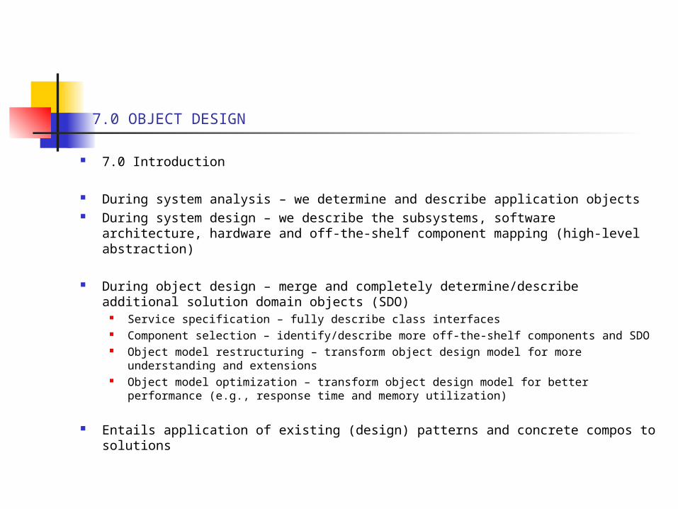
7.0 Introduction
During system analysis – we determine and describe application objects During system design – we describe the subsystems, software architecture,
hardware and off-the-shelf component mapping (high-level abstraction)
During object design – merge and completely determine/describe additional solution domain objects (SDO)
Service specification – fully describe class interfaces Component selection – identify/describe more off-the-shelf components and SDO Object model restructuring – transform object design model for more
understanding and extensions Object model optimization – transform object design model for better performance
(e.g., response time and memory utilization)
Entails application of existing (design) patterns and concrete compos to solutions
7.0 OBJECT DESIGN
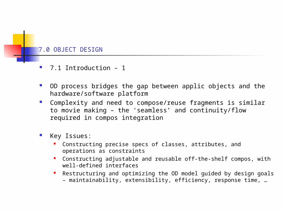
7.1 Introduction – 1
OD process bridges the gap between applic objects and the hardware/software platform
Complexity and need to compose/reuse fragments is similar to movie making – the ‘seamless’ and continuity/flow required in compos integration
Key Issues: Constructing precise specs of classes, attributes, and operations as
constraints Constructing adjustable and reusable off-the-shelf compos, with well-
defined interfaces Restructuring and optimizing the OD model guided by design goals –
maintainability, extensibility, efficiency, response time, …
7.0 OBJECT DESIGN
7.2 Overview of OD
Analysis – identifies objects from user-visible view, bridging gap between applic & solution domains
System design – selecting off-the-shelf compos, middleware, user-interfaces, libraries and frameworks to bridge gap between applic & solution domains through mapping
Object design – refine analysis and system design models/objects with new objects, adjustments to off-the-shelf, precise interface specs, and partitioning/layering into sets of classes for subsystem-implementations
(See Fig 7-1)
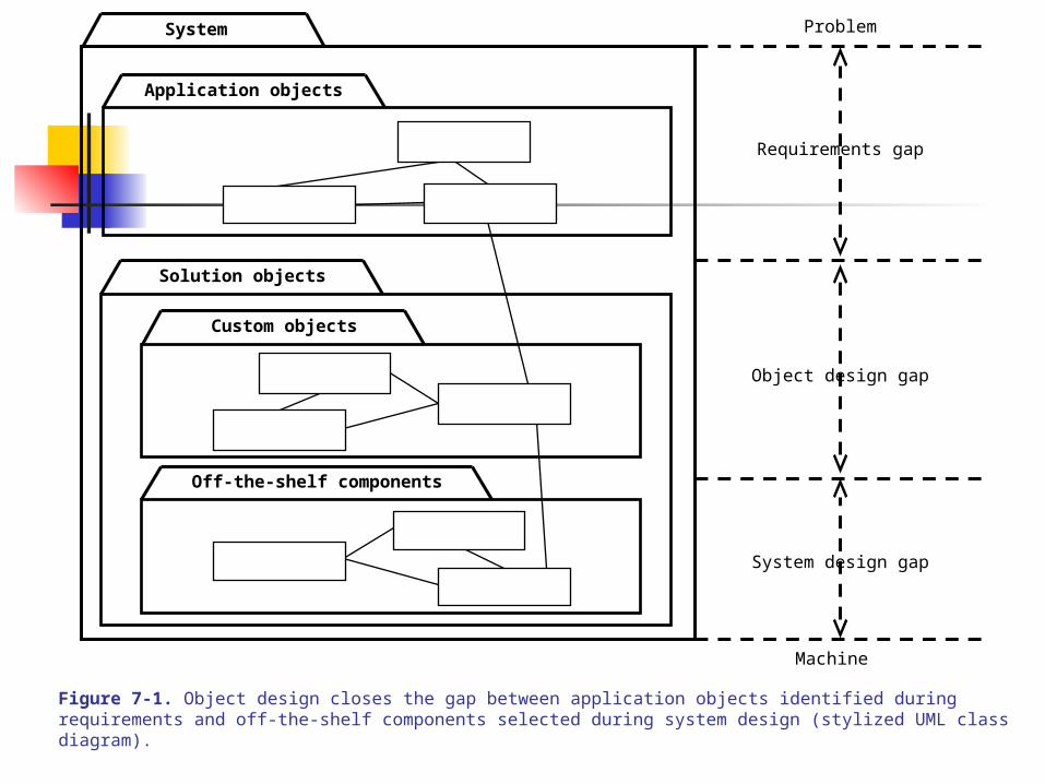
Figure 7-1. Object design closes the gap between application objects identified during requirements and off-the-shelf components selected during system design (stylized UML class diagram).
Problem
Machine
System design gap
Object design gap
Requirements gap
System
Application objects
Solution objects
Custom objects
Off-the-shelf components
7.0 OBJECT DESIGN
7.2 Overview – 2
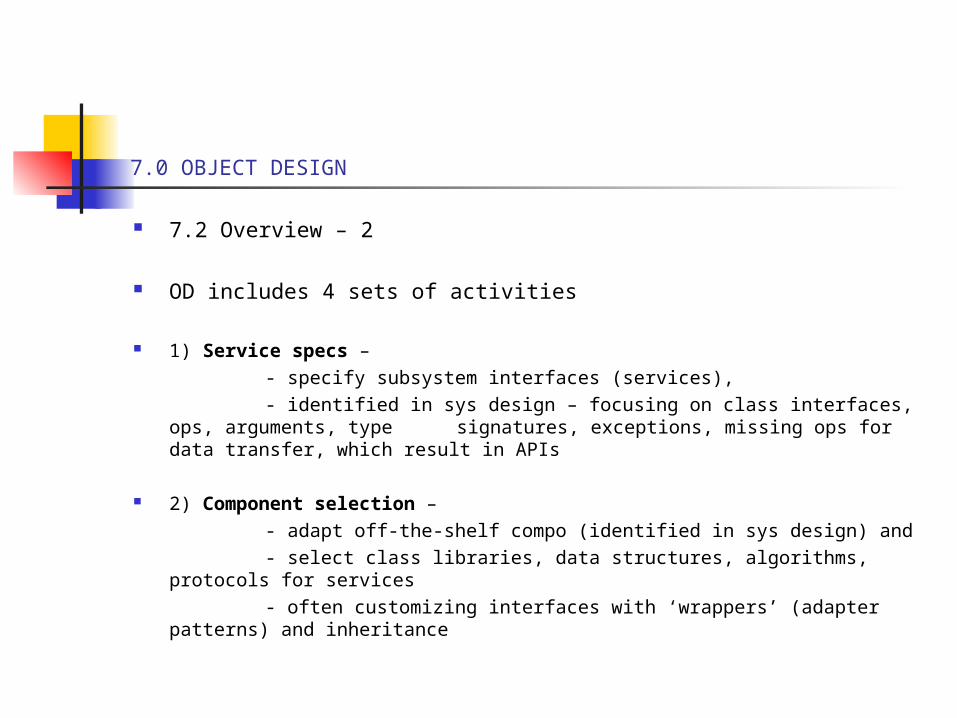
OD includes 4 sets of activities
1) Service specs – - specify subsystem interfaces (services), - identified in sys design – focusing on class interfaces, ops,
arguments, type signatures, exceptions, missing ops for data transfer, which result in APIs
2) Component selection – - adapt off-the-shelf compo (identified in sys design) and - select class libraries, data structures, algorithms, protocols for
services - often customizing interfaces with ‘wrappers’ (adapter patterns) and
inheritance
7.0 OBJECT DESIGN
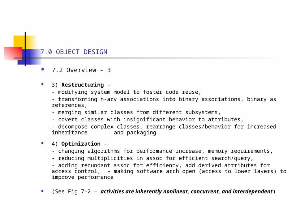
7.2 Overview - 3
3) Restructuring – - modifying system model to foster code reuse, - transforming n-ary associations into binary associations, binary as
references, - merging similar classes from different subsystems, - covert classes with insignificant behavior to attributes, - decompose complex classes, rearrange classes/behavior for increased
inheritance and packaging
4) Optimization – - changing algorithms for performance increase, memory requirements, - reducing multiplicities in assoc for efficient search/query, - adding redundant assoc for efficiency, add derived attributes for access
control, - making software arch open (access to lower layers) to improve performance
(See Fig 7-2 – activities are inherently nonlinear, concurrent, and interdependent)
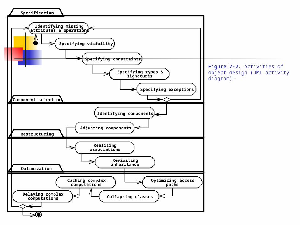
Figure 7-2. Activities of object design (UML activity diagram).
Identifying components
Adjusting components
Specifying constraints
Collapsing classes
Specifying types &
Identifying missingattributes & operations
Specifying visibility
Specification
signatures
Optimization
Specifying exceptions
Restructuring
Realizingassociations
Revisitinginheritance
Optimizing accesspaths
Caching complexcomputations
Delaying complexcomputations
Component selection
7.0 OBJECT DESIGN
7.3 Object Design Concepts
Applications vs. solution objects
1) application (domain) objects – concepts of the domain which the system operates on
2) solution objects – components not found in the applic domain, constitute op environment
Again,
i) at analysis – identify application objects, their relationships, attributes, and operations (no details of types or parameters)ii) at sys design – identify subsystems and solution objectsiii) at ob design – refine and detail both application and solution objects, any remaining
7.0 OBJECT DESIGN
7.3 Object Design Concepts – 2
Types, Signatures, and Visibility
Add type and visibility (scope) information to analysis/system models
Type – the range of values the parameters can take, including parameters and returns values and their constraints
Signature – the tuple of parameters of an operation and the return value type E.g., put() has signature of: (Object, Object) : void
E.g., get() has signature of: (Object) : Object
Visibility – to extent an object attribute/operation can be used by other classes, 3 levels:i) [-] private – attributes/ops can be accessed by any other (subclasses or
classes)ii) [#] protected – attributes/ops accessed only by defining class and its
descendantsiii) [+] public – accessed by any other class
(See Fig 7-3)
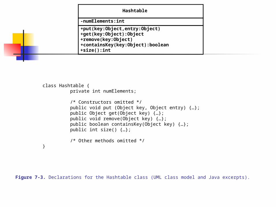
Figure 7-3. Declarations for the Hashtable class (UML class model and Java excerpts).
Hashtable
+put(key:Object,entry:Object)+get(key:Object):Object+remove(key:Object)+containsKey(key:Object):boolean+size():int
-numElements:int
class Hashtable {private int numElements;
/* Constructors omitted */public void put (Object key, Object entry) {…};public Object get(Object key) {…};public void remove(Object key) {…};public boolean containsKey(Object key) {…};public int size() {…};
/* Other methods omitted */}
7.0 OBJECT DESIGN
7.3 Object Design Concepts - 3
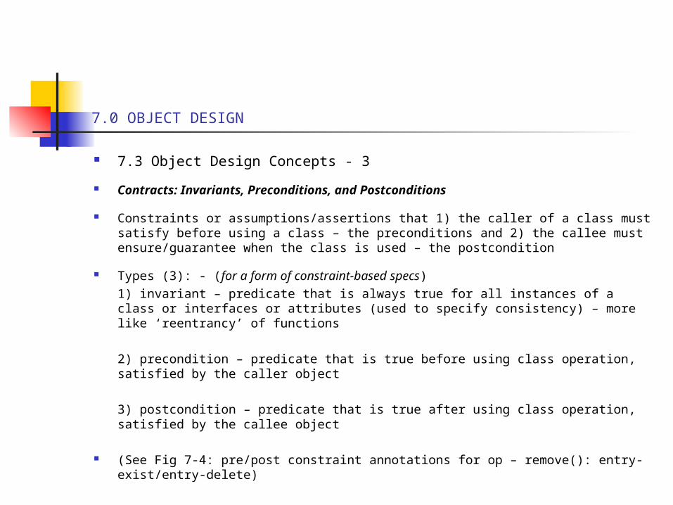
Contracts: Invariants, Preconditions, and Postconditions
Constraints or assumptions/assertions that 1) the caller of a class must satisfy before using a class – the preconditions and 2) the callee must ensure/guarantee when the class is used – the postcondition
Types (3): - (for a form of constraint-based specs)1) invariant – predicate that is always true for all instances of a class or interfaces or attributes (used to specify consistency) – more like ‘reentrancy’ of functions
2) precondition – predicate that is true before using class operation, satisfied by the caller object
3) postcondition – predicate that is true after using class operation, satisfied by the callee object
(See Fig 7-4: pre/post constraint annotations for op – remove(): entry-exist/entry-delete)
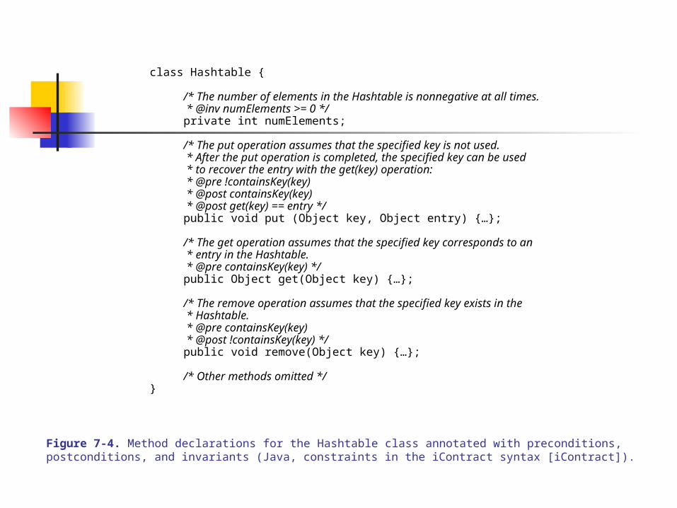
Figure 7-4. Method declarations for the Hashtable class annotated with preconditions, postconditions, and invariants (Java, constraints in the iContract syntax [iContract]).
class Hashtable {
/* The number of elements in the Hashtable is nonnegative at all times. * @inv numElements >= 0 */private int numElements;
/* The put operation assumes that the specified key is not used. * After the put operation is completed, the specified key can be used * to recover the entry with the get(key) operation: * @pre !containsKey(key) * @post containsKey(key) * @post get(key) == entry */public void put (Object key, Object entry) {…};
/* The get operation assumes that the specified key corresponds to an * entry in the Hashtable. * @pre containsKey(key) */public Object get(Object key) {…};
/* The remove operation assumes that the specified key exists in the * Hashtable. * @pre containsKey(key) * @post !containsKey(key) */public void remove(Object key) {…};
/* Other methods omitted */}
7.0 OBJECT DESIGN
7.3 Object Design Concepts – 4
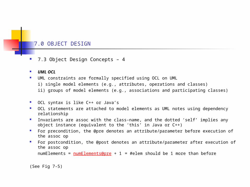
UML OCL UML constraints are formally specified using OCL on UML
i) single model elements (e.g., attributes, operations and classes)ii) groups of model elements (e.g., associations and participating classes)
OCL syntax is like C++ or Java’s OCL statements are attached to model elements as UML notes using dependency
relationship Invariants are assoc with the class-name, and the dotted ‘self’ implies any object instance
(equivalent to the ‘this’ in Java or C++) For precondition, the @pre denotes an attribute/parameter before execution of the assoc op For postcondition, the @post denotes an attribute/parameter after execution of the assoc op
numElements = numElements@pre + 1 = #elem should be 1 more than before
(See Fig 7-5)
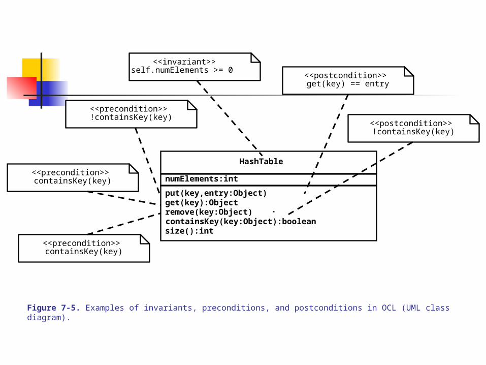
Figure 7-5. Examples of invariants, preconditions, and postconditions in OCL (UML class diagram).
<<invariant>>self.numElements >= 0
HashTable
put(key,entry:Object)get(key):Objectremove(key:Object)containsKey(key:Object):booleansize():int
numElements:int
<<postcondition>>!containsKey(key)
<<postcondition>>get(key) == entry
<<precondition>>containsKey(key)
<<precondition>>!containsKey(key)
<<precondition>>containsKey(key)
7.0 OBJECT DESIGN
7.3 Object Design Concepts – 5
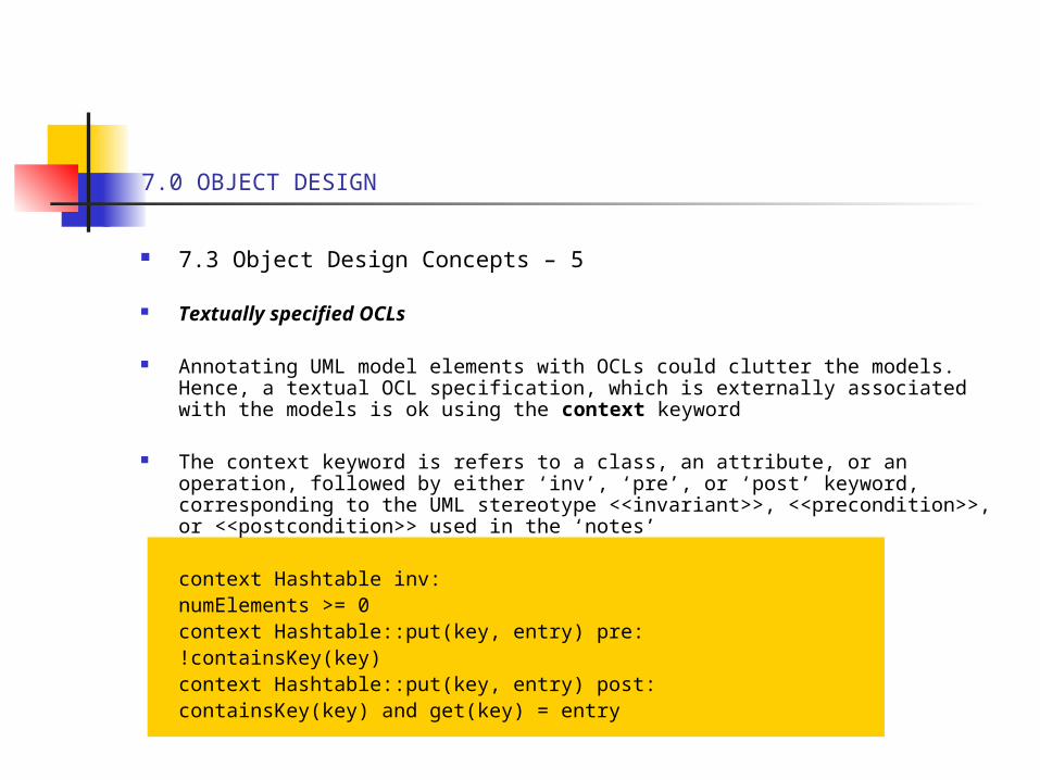
Textually specified OCLs
Annotating UML model elements with OCLs could clutter the models. Hence, a textual OCL specification, which is externally associated with the models is ok using the context keyword
The context keyword is refers to a class, an attribute, or an operation, followed by either ‘inv’, ‘pre’, or ‘post’ keyword, corresponding to the UML stereotype <<invariant>>, <<precondition>>, or <<postcondition>> used in the ‘notes’
context Hashtable inv:numElements >= 0context Hashtable::put(key, entry) pre:!containsKey(key)context Hashtable::put(key, entry) post:containsKey(key) and get(key) = entry
7.0 OBJECT DESIGN
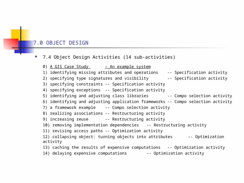
7.4 Object Design Activities (14 sub-activities)
0) A GIS Case Study – An example system1) identifying missing attributes and operations -- Specification activity2) specifying type signatures and visibility -- Specification activity3) specifying constraints -- Specification activity4) specifying exceptions -- Specification activity5) identifying and adjusting class libraries -- Compo selection activity6) identifying and adjusting application frameworks -- Compo selection activity7) a framework example -- Compo selection activity8) realizing associations -- Restructuring activity9) increasing reuse -- Restructuring activity10) removing implementation dependencies -- Restructuring activity11) revising access paths -- Optimization activity12) collapsing object: turning objects into attributes -- Optimization activity13) caching the results of expensive computations -- Optimization activity14) delaying expensive computations -- Optimization activity
7.0 OBJECT DESIGN
7.4 Object Design Activities 0. The GIS System
System Descriptions and Specificationa) An emission modeling system (JEWEL) – for simulating/visualizing air
pollution datab) Data sources – point (factories/powerplants), area (cities), mobile
(cars/trains/trucks)c) Grid cells of map, with 1 hr/day simulationd) Goal is air regulation in mapped regione) Manages GIS data as sets of polygons and segments organized into display-
units (layers)
The GIS Object Model (See Fig. 7-7)
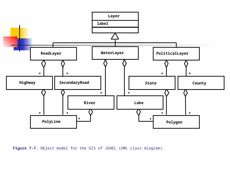
Figure 7-7. Object model for the GIS of JEWEL (UML class diagram).
* *
**
* *
**
* *
* *
PoliticalLayerWaterLayerRoadLayer
Highway SecondaryRoad
River Lake
State County
PolyLine Polygon
Layer
label
7.0 OBJECT DESIGN
7.4 Object Design Activities 0. The GIS System
System Descriptions and Specification
The functional model (use case) – abstract, specifies selection of zoom-in, zoom-out of points, not algorithmic
(Fig 7-8)
7.0 OBJECT DESIGN
7.4 Object Design Activities
0. The GIS Systems – 1
The object model (Fig 7-7 – we discussed above)
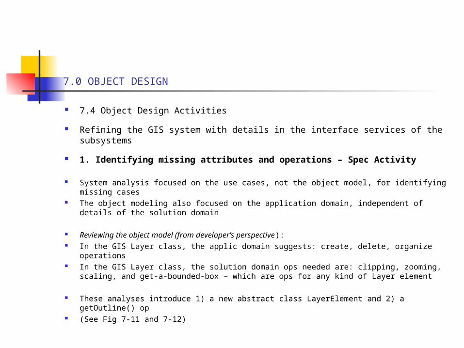
The dynamic model - the sequence diagram depicts the ZoomIn control/data flow of the ZoomMap use case
(Fig 7-11)
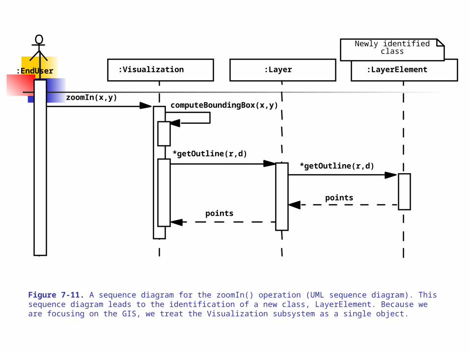
Figure 7-11. A sequence diagram for the zoomIn() operation (UML sequence diagram). This sequence diagram leads to the identification of a new class, LayerElement. Because we are focusing on the GIS, we treat the Visualization subsystem as a single object.
:EndUser
zoomIn(x,y)computeBoundingBox(x,y)
*getOutline(r,d)
*getOutline(r,d)
points
points
:Layer:Visualization :LayerElement
Newly identifiedclass
7.0 OBJECT DESIGN
7.4 Object Design Activities
0. The GIS Systems – 1
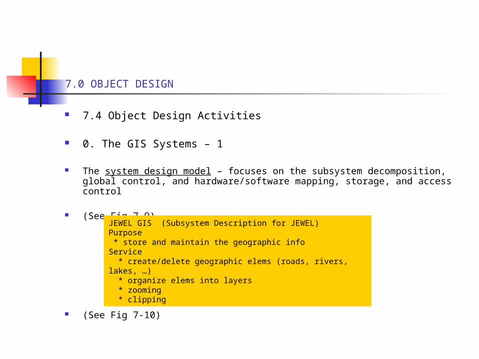
The system design model – focuses on the subsystem decomposition, global control, and hardware/software mapping, storage, and access control
(See Fig 7-9)
(See Fig 7-10)
JEWEL GIS (Subsystem Description for JEWEL)Purpose * store and maintain the geographic infoService * create/delete geographic elems (roads, rivers, lakes, …) * organize elems into layers * zooming * clipping
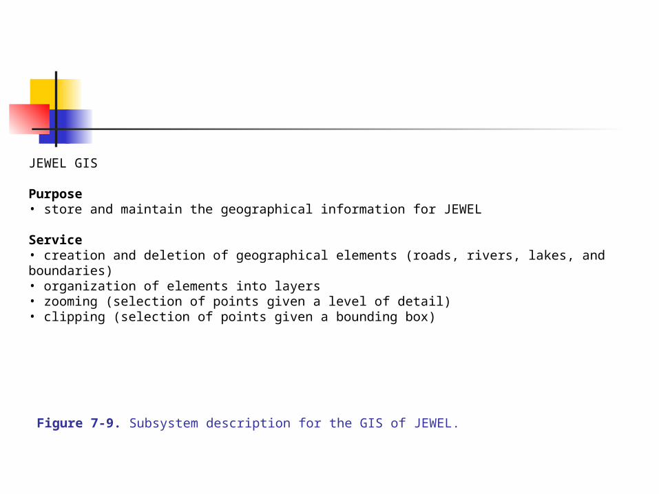
Figure 7-9. Subsystem description for the GIS of JEWEL.
JEWEL GIS
Purpose• store and maintain the geographical information for JEWEL
Service• creation and deletion of geographical elements (roads, rivers, lakes, and boundaries)• organization of elements into layers• zooming (selection of points given a level of detail)• clipping (selection of points given a bounding box)
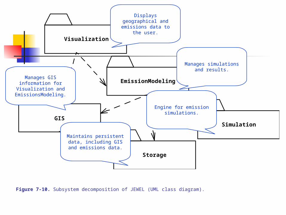
Figure 7-10. Subsystem decomposition of JEWEL (UML class diagram).
Visualization
Simulation
EmissionModeling
GIS
Storage
Displays geographical and emissions data to the user.
Manages simulations and results.
Engine for emission simulations.
Maintains persistent data, including GIS and emissions
data.
Manages GIS information for Visualization and
EmissionsModeling.
7.0 OBJECT DESIGN
7.4 Object Design Activities
Refining the GIS system with details in the interface services of the subsystems
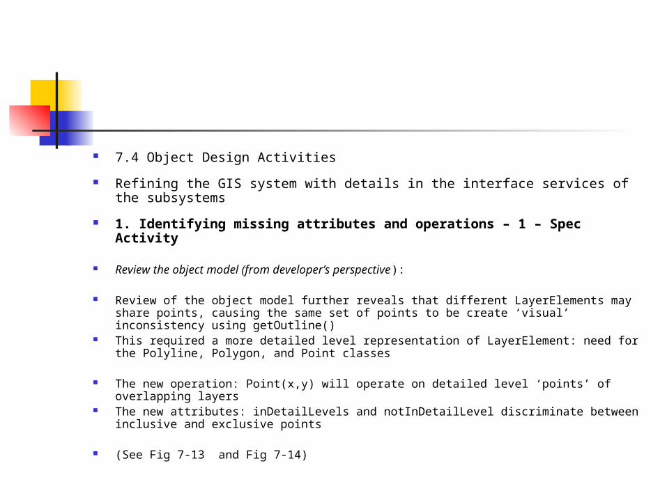
1. Identifying missing attributes and operations – Spec Activity
System analysis focused on the use cases, not the object model, for identifying missing cases
The object modeling also focused on the application domain, independent of details of the solution domain
Reviewing the object model (from developer’s perspective): In the GIS Layer class, the applic domain suggests: create, delete, organize operations In the GIS Layer class, the solution domain ops needed are: clipping, zooming, scaling,
and get-a-bounded-box – which are ops for any kind of Layer element
These analyses introduce 1) a new abstract class LayerElement and 2) a getOutline() op
(See Fig 7-11 and 7-12)
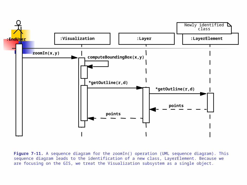
Figure 7-11. A sequence diagram for the zoomIn() operation (UML sequence diagram). This sequence diagram leads to the identification of a new class, LayerElement. Because we are focusing on the GIS, we treat the Visualization subsystem as a single object.
:EndUser
zoomIn(x,y)computeBoundingBox(x,y)
*getOutline(r,d)
*getOutline(r,d)
points
points
:Layer:Visualization :LayerElement
Newly identifiedclass
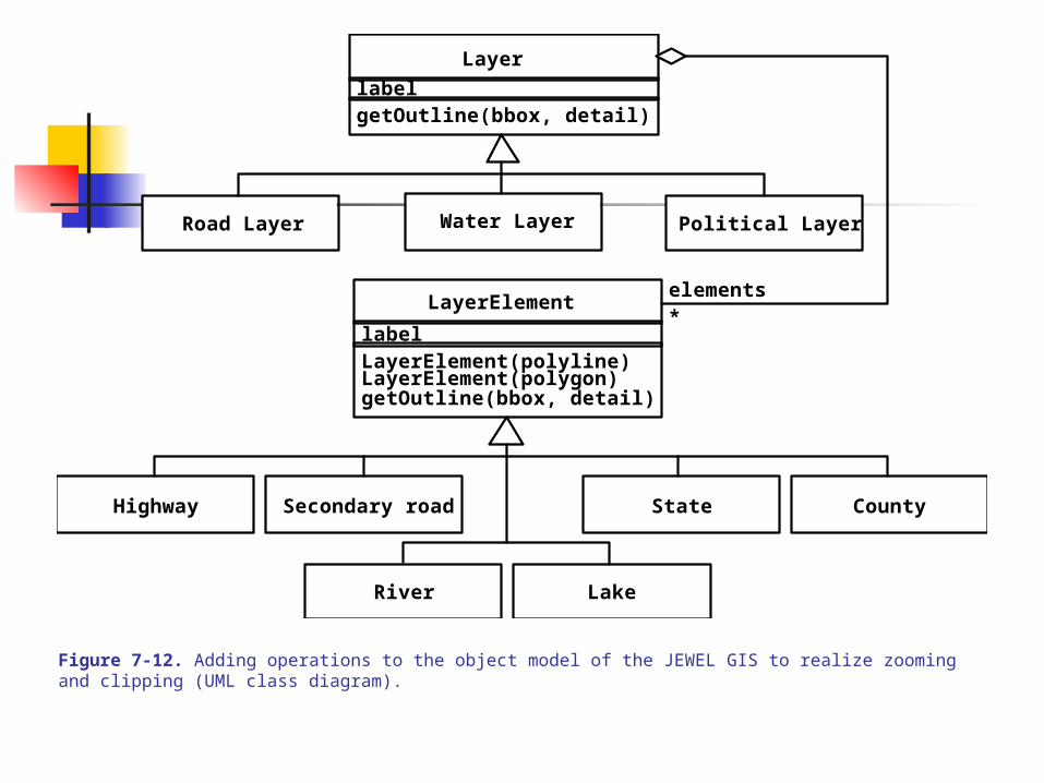
Figure 7-12. Adding operations to the object model of the JEWEL GIS to realize zooming and clipping (UML class diagram).
Layer
getOutline(bbox, detail)
LayerElement
label
Political LayerWater LayerRoad Layer
label
Highway Secondary road
River Lake
State County
LayerElement(polyline)LayerElement(polygon)getOutline(bbox, detail)
elements*
7.4 Object Design Activities
Refining the GIS system with details in the interface services of the subsystems
1. Identifying missing attributes and operations – 1 – Spec Activity
Review the object model (from developer’s perspective):
Review of the object model further reveals that different LayerElements may share points, causing the same set of points to be create ‘visual’ inconsistency using getOutline()
This required a more detailed level representation of LayerElement: need for the Polyline, Polygon, and Point classes
The new operation: Point(x,y) will operate on detailed level ‘points’ of overlapping layers
The new attributes: inDetailLevels and notInDetailLevel discriminate between inclusive and exclusive points
(See Fig 7-13 and Fig 7-14)
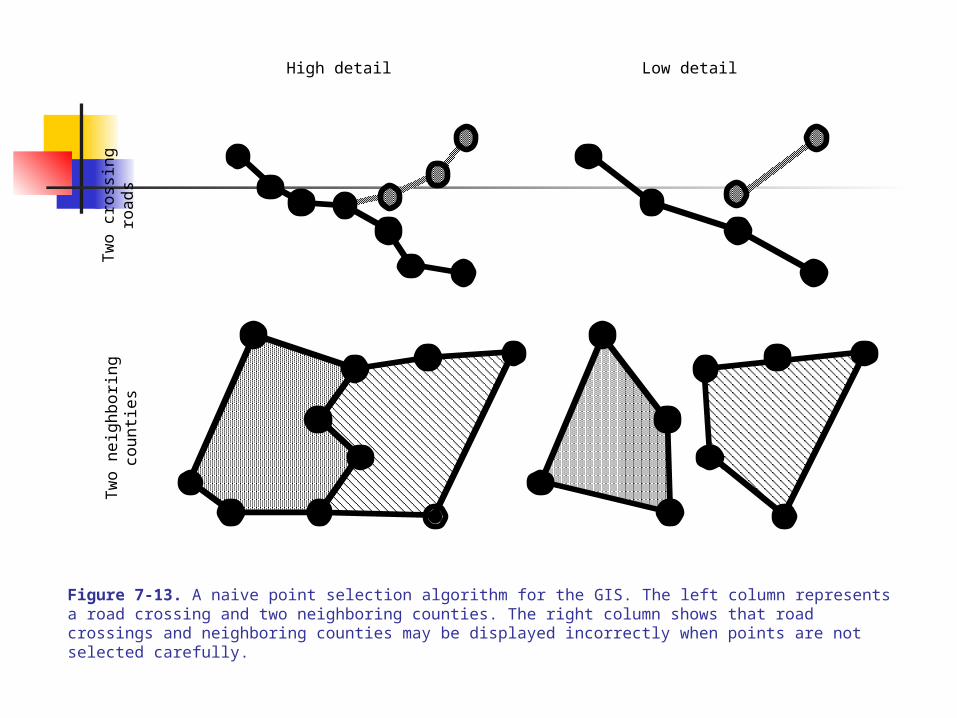
Figure 7-13. A naive point selection algorithm for the GIS. The left column represents a road crossing and two neighboring counties. The right column shows that road crossings and neighboring counties may be displayed incorrectly when points are not selected carefully.
High detail Low detail
Tw
o cr
ossi
ngro
ads
Tw
o ne
ighb
orin
gco
unti
es
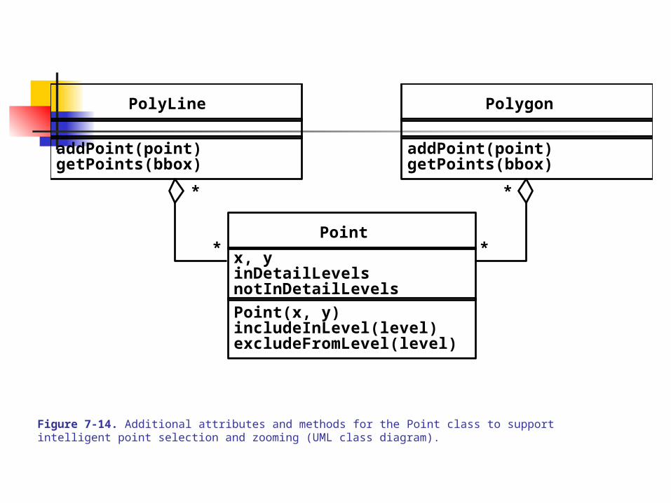
Figure 7-14. Additional attributes and methods for the Point class to support intelligent point selection and zooming (UML class diagram).
Point
x, y
Point(x, y)includeInLevel(level)excludeFromLevel(level)
notInDetailLevels
* *
PolyLine
addPoint(point)getPoints(bbox)
Polygon
addPoint(point)getPoints(bbox)
inDetailLevels
* *
7.0 OBJECT DESIGN
7.4 Object Design Activities – 1
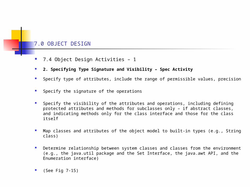
2. Specifying Type Signature and Visibility – Spec Activity
Specify type of attributes, include the range of permissible values, precision
Specify the signature of the operations
Specify the visibility of the attributes and operations, including defining protected attributes and methods for subclasses only – if abstract classes, and indicating methods only for the class interface and those for the class itself
Map classes and attributes of the object model to built-in types (e.g., String class)
Determine relationship between system classes and classes from the environment (e.g., the java.util package and the Set Interface, the java.awt API, and the Enumeration interface)
(See Fig 7-15)
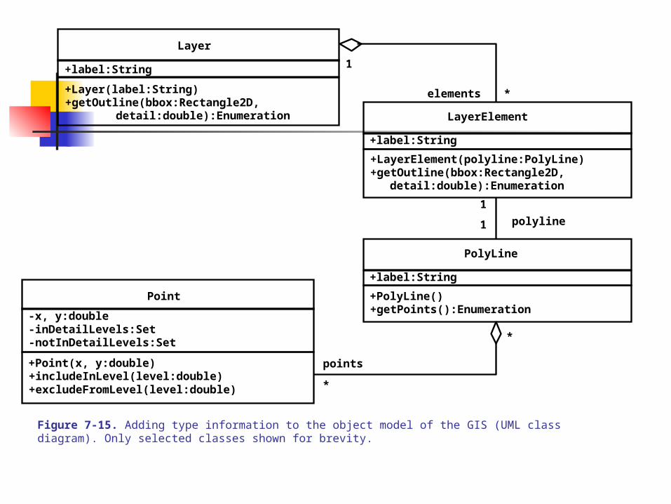
Figure 7-15. Adding type information to the object model of the GIS (UML class diagram). Only selected classes shown for brevity.
Layer
LayerElement
+label:String
+label:String
Point
+Point(x, y:double)+includeInLevel(level:double)+excludeFromLevel(level:double)
+LayerElement(polyline:PolyLine)+getOutline(bbox:Rectangle2D,
detail:double):Enumeration
+Layer(label:String)
detail:double):Enumeration+getOutline(bbox:Rectangle2D,
*
points
*
elements
-x, y:double
-notInDetailLevels:Set-inDetailLevels:Set
PolyLine
+label:String
+PolyLine()+getPoints():Enumeration
1
1
*
1
polyline
7.0 OBJECT DESIGN
7.4 Object Design Activities – 2
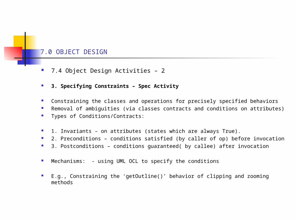
3. Specifying Constraints – Spec Activity
Constraining the classes and operations for precisely specified behaviors Removal of ambiguities (via classes contracts and conditions on attributes) Types of Conditions/Contracts:
1. Invariants – on attributes (states which are always True). 2. Preconditions – conditions satisfied (by caller of op) before invocation 3. Postconditions – conditions guaranteed( by callee) after invocation
Mechanisms: - using UML OCL to specify the conditions
E.g., Constraining the ‘getOutline()’ behavior of clipping and zooming methods
7.0 OBJECT DESIGN
7.4 Object Design Activities – 3
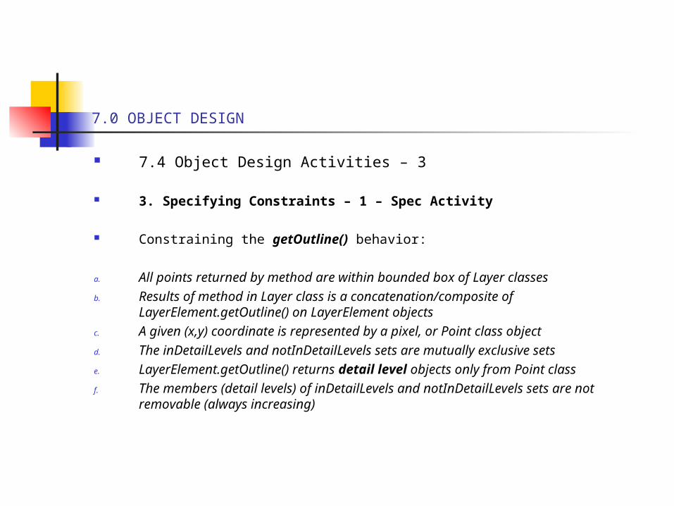
3. Specifying Constraints – 1 – Spec Activity
Constraining the getOutline() behavior:
a. All points returned by method are within bounded box of Layer classesb. Results of method in Layer class is a concatenation/composite of
LayerElement.getOutline() on LayerElement objectsc. A given (x,y) coordinate is represented by a pixel, or Point class objectd. The inDetailLevels and notInDetailLevels sets are mutually exclusive setse. LayerElement.getOutline() returns detail level objects only from Point classf. The members (detail levels) of inDetailLevels and notInDetailLevels sets are
not removable (always increasing)
7.0 OBJECT DESIGN
7.4 Object Design Activities – 4
3. Specifying Constraints – 2 – Spec Activity
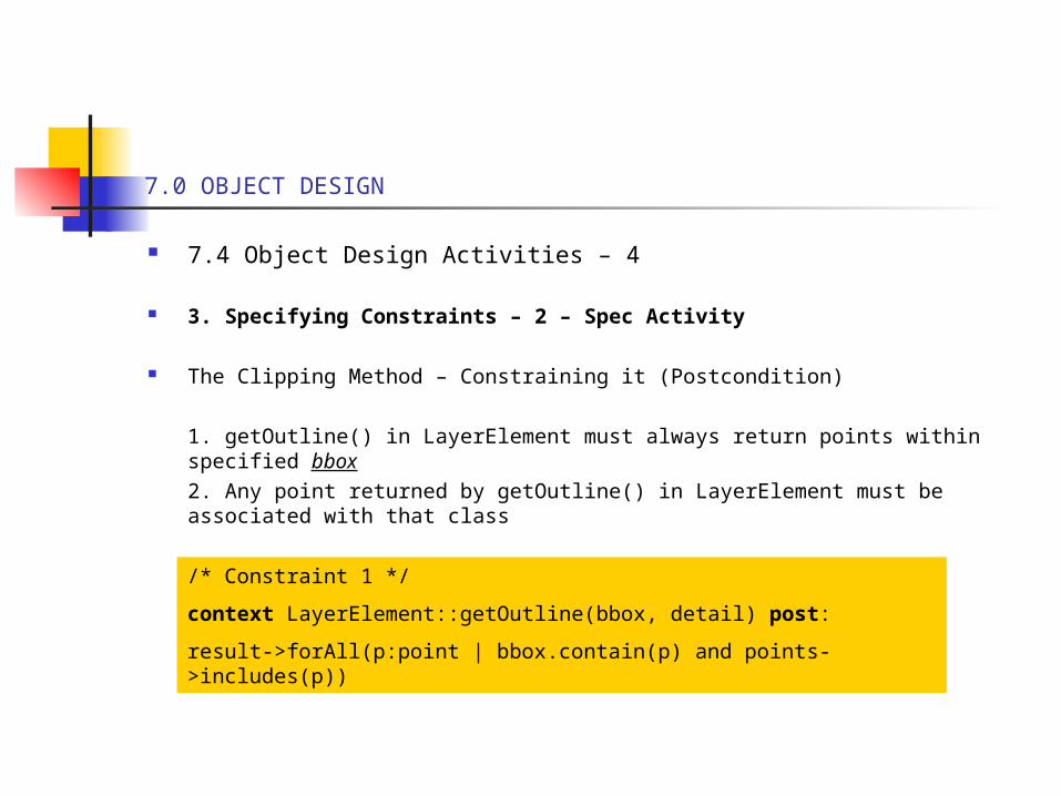
The Clipping Method – Constraining it (Postcondition)
1. getOutline() in LayerElement must always return points within specified bbox2. Any point returned by getOutline() in LayerElement must be associated with that class
/* Constraint 1 */
context LayerElement::getOutline(bbox, detail) post:
result->forAll(p:point | bbox.contain(p) and points->includes(p))
7.0 OBJECT DESIGN
7.4 Object Design Activities – 5
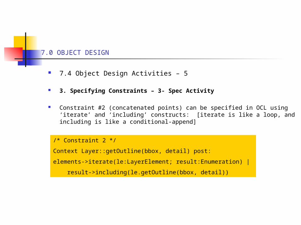
3. Specifying Constraints – 3- Spec Activity
Constraint #2 (concatenated points) can be specified in OCL using ‘iterate’ and ‘including’ constructs: [iterate is like a loop, and including is like a conditional-append]
/* Constraint 2 */
Context Layer::getOutline(bbox, detail) post:
elements->iterate(le:LayerElement; result:Enumeration) |
result->including(le.getOutline(bbox, detail))
7.0 OBJECT DESIGN
7.4 Object Design Activities – 6
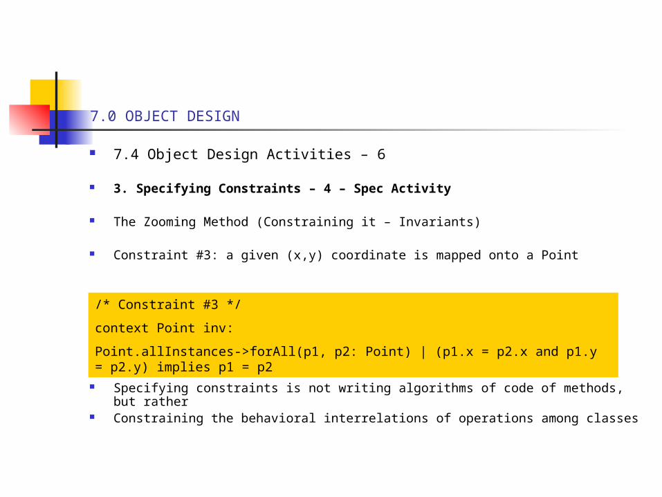
3. Specifying Constraints – 4 – Spec Activity
The Zooming Method (Constraining it – Invariants)
Constraint #3: a given (x,y) coordinate is mapped onto a Point
Specifying constraints is not writing algorithms of code of methods, but rather Constraining the behavioral interrelations of operations among classes
/* Constraint #3 */
context Point inv:
Point.allInstances->forAll(p1, p2: Point) | (p1.x = p2.x and p1.y = p2.y) implies p1 = p2
7.0 OBJECT DESIGN
7.4 Object Design Activities – 7
4. Specifying Exceptions : - Spec Activity
A) These are specifications of constraints (Preconditions) that must be satisfied by the caller before the operations is invoked – Errors that must be raised, later, and handled
B) These are often associated with violations of preconditions C) Notation: attach UML OCL preconditions to ops and associate the precon with a
dependency to an exception object D) The exception (<<exception>>) is classed and associated with the class(es) with
ops
(See Fig 7-16)
Where reliability is very important, examine all parameters associated with each op in the classes for violations of boundary, constraint, etc. conditions or values and apply OCL preconditions
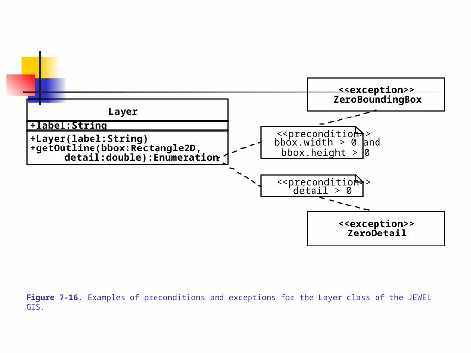
Figure 7-16. Examples of preconditions and exceptions for the Layer class of the JEWEL GIS.
Layer
+Layer(label:String)
detail:double):Enumeration
+label:String
+getOutline(bbox:Rectangle2D,
<<precondition>>bbox.width > 0 and
<<precondition>>detail > 0
bbox.height > 0
<<exception>>ZeroDetail
<<exception>>ZeroBoundingBox
7.0 OBJECT DESIGN
7.4 Object Design Activities – 8
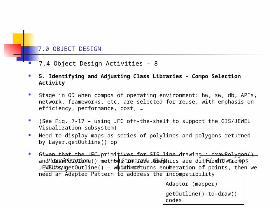
5. Identifying and Adjusting Class Libraries – Compo Selection Activity
Stage in OD when compos of operating environment: hw, sw, db, APIs, network, frameworks, etc. are selected for reuse, with emphasis on efficiency, performance, cost, …
(See Fig. 7-17 – using JFC off-the-shelf to support the GIS/JEWEL Visualization subsystem)
Need to display maps as series of polylines and polygons returned by Layer.getOutline() op
Given that the JFC primitives for GIS line drawing : drawPolygon() and drawPolyline() methods in Java.Graphics are different from JEWEL’s getOutline() – which returns enumeration of points, then we need an Adapter Pattern to address the incompatibility
Visualization Subsys
Standard JEWEL interf
Adaptor (mapper)
getOutline()-to-draw() codes
JFC draws… ops
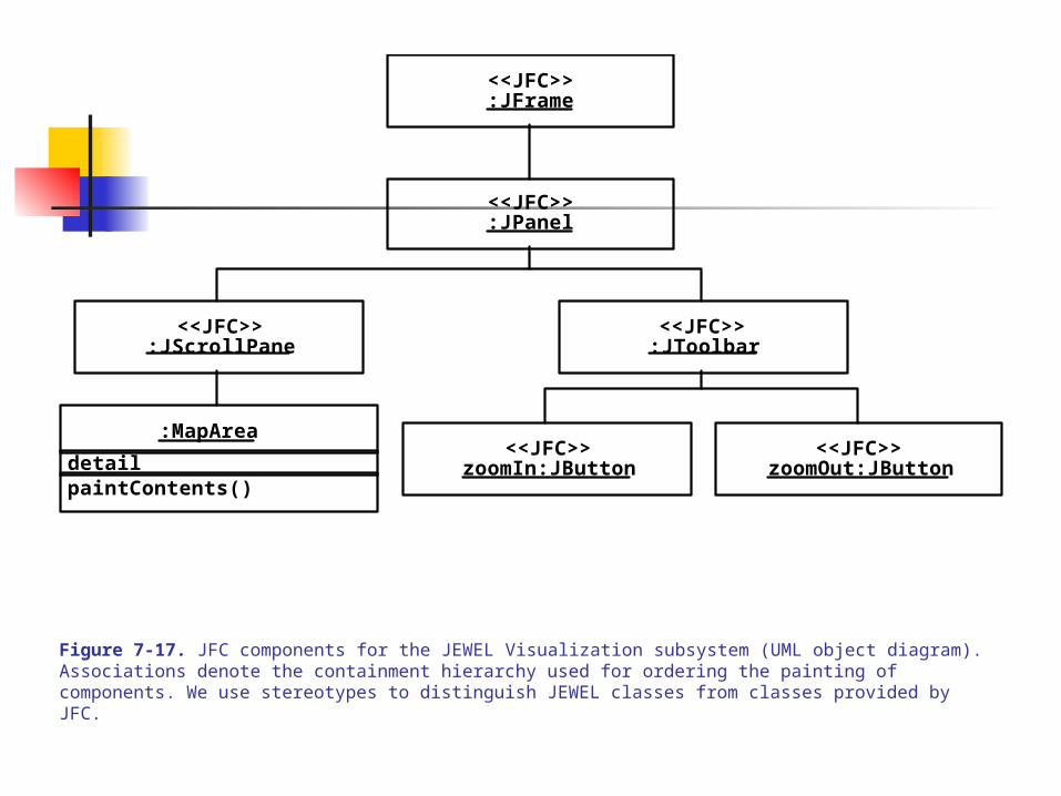
Figure 7-17. JFC components for the JEWEL Visualization subsystem (UML object diagram). Associations denote the containment hierarchy used for ordering the painting of components. We use stereotypes to distinguish JEWEL classes from classes provided by JFC.
<<JFC>>:JFrame
<<JFC>>:JPanel
<<JFC>>:JScrollPane
<<JFC>>:JToolbar
:MapArea
paintContents()
<<JFC>>zoomIn:JButton
<<JFC>>zoomOut:JButtondetail
7.0 OBJECT DESIGN
7.4 Object Design Activities – 9
6. Identifying and Adjusting Application Frameworks – Compo Selection Activity
Application frameworks are like ASIC (Application Specific Integrated Circuits) – in that they are reusable, partial products targeted/design for specific domains solutions.
Besides reusability, AF’s are extendible using hook methods (parameterization, dynamic polymorphism, pragmas, etc.), allowing decoupling of interfaces from behaviors and customization
7.0 OBJECT DESIGN
7.4 Object Design Activities – 10
6. Identifying and Adjusting Application Frameworks –1 – Compo Selection Activity
Types of Application Frameworks (by area of need in software development): 1. Infrastructure Frameworks – e.g., frameworks for OS, debuggers, comm tasks,
user-interface design components, and system-wide infrastructure compos for software process
2. Middleware Frameworks – for integrating existing distributed applics and compos, e.g., Microsoft DCOM, Java RMI, WebObjects, CORBA facilities, DBMS-glues
3. Enterprise AF’s – application-specific (more like ASICs) in avionics, telecomm, embedded sys, engineering, business applics, and hardware design – facilitating end-user application development
7.0 OBJECT DESIGN
7.4 Object Design Activities – 11
6. Identifying and Adjusting Application Frameworks –2 – Compo Selection Activity
Types of Application Frameworks (by techniques used): 1. Whitebox Frameworks – employs inheritance and dynamic binding for
extensibility (using, e.g., dynamic polymorphism, internal structures for type extension and class-wide types for subclassing and operation overloading/overriding and patterns)
Makes AF’s tightly coupled to applications, more specificity, and recompilations after changes
2. Blackbox frameworks – focuses on interface definitions for component assembly (using, e.g., plug-ins and such patterns as the Delegation Pattern)
More difficult to develop but easier to extend and reconfig dynamically for wider areas of applications, and emphasizes run-time class/object binding of, e.g., operations via pointers/pragmas
7.0 OBJECT DESIGN
7.4 Object Design Activities – 12
6. Identifying and Adjusting Application Frameworks –3 – Compo Selection Activity
Distinguishing between AF’s, Design Patterns, and Class Libraries
DP vs. AFs: DP focus on abstract designs for reuse using small collection of cooperating classes as building blocks; AFs focus on reuse of concrete designs / algorithms / implementations in a development language
CL vs. AFs: CL’s have classes for reuse but a not domain specific and have smaller scope, and contain passive classes for general usage (e.g., classes for string, arrays, stack, numerics, bit-manipulation functions); AF’s have classes with more cooperation and reusable patterns for a family of related applications, and contain active classes with flow control
CL’s and AF’s are complementary – CL’s utilize classes (and methods) of AF’s for specific implementations and AF’s utilize abstract designs of CL’s to simplify or handle generic functions to speed-up development
7.0 OBJECT DESIGN
7.4 Object Design Activities – 13
6. Identifying and Adjusting Application Frameworks –2 – Compo Selection Activity
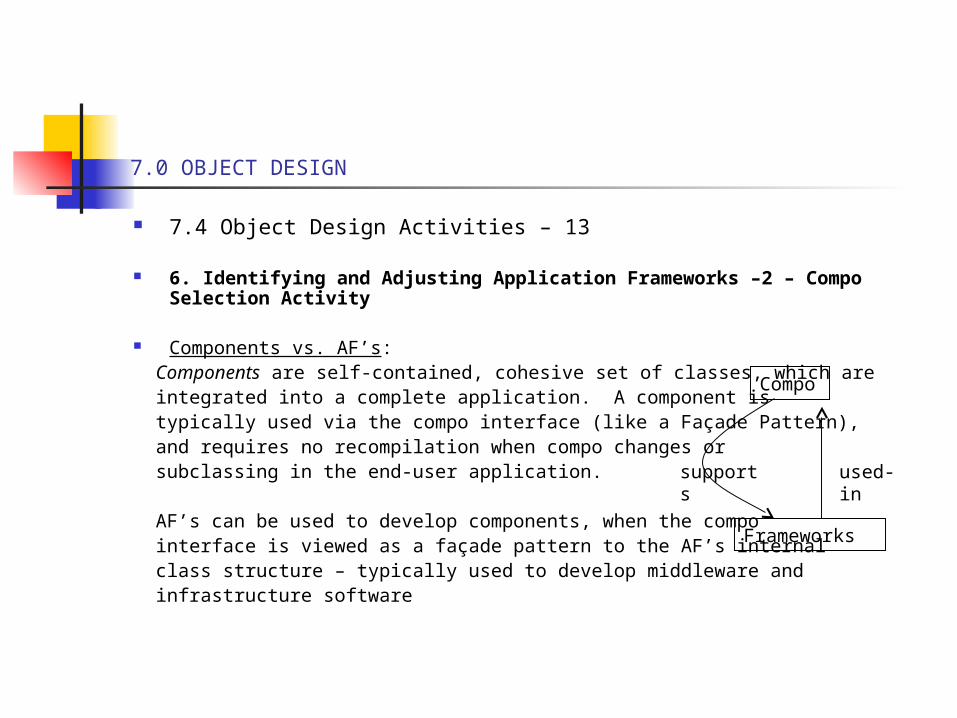
Components vs. AF’s: Components are self-contained, cohesive set of classes, which are integrated into a complete application. A component is typically used via the compo interface (like a Façade Pattern), and requires no recompilation when compo changes or subclassing in the end-user application. AF’s can be used to develop components, when the compo interface is viewed as a façade pattern to the AF’s internal class structure – typically used to develop middleware and infrastructure software
Compo
Frameworks
used-insupports
7.0 OBJECT DESIGN
7.4 Object Design Activities –14
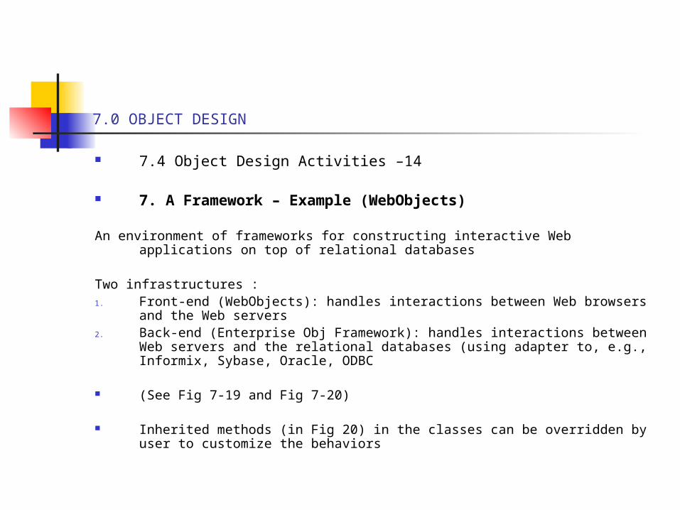
7. A Framework – Example (WebObjects)
An environment of frameworks for constructing interactive Web applications on top of relational databases
Two infrastructures :1. Front-end (WebObjects): handles interactions between Web browsers and the
Web servers2. Back-end (Enterprise Obj Framework): handles interactions between Web
servers and the relational databases (using adapter to, e.g., Informix, Sybase, Oracle, ODBC
(See Fig 7-19 and Fig 7-20)
Inherited methods (in Fig 20) in the classes can be overridden by user to customize the behaviors
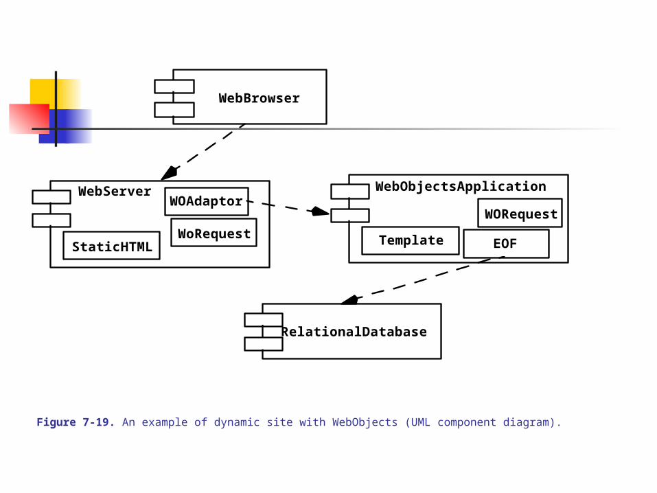
Figure 7-19. An example of dynamic site with WebObjects (UML component diagram).
WebBrowser
RelationalDatabase
StaticHTML
WOAdaptorWebServer
WoRequest Template
WebObjectsApplication
WORequest
EOF
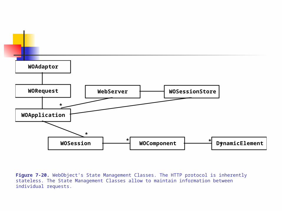
Figure 7-20. WebObject’s State Management Classes. The HTTP protocol is inherently stateless. The State Management Classes allow to maintain information between individual requests.
WOSession WOComponent DynamicElement
WOApplication
WORequest
WOAdaptor
*
*
**
WebServer WOSessionStore
*
7.0 OBJECT DESIGN
7.4 Object Design Activities – 15
8. Realizing Associations – Restructuring Activity
This set of activities involves the transformation of the object design model into a representation closer to the target machine
Associations: uni- or bi-directional links between objects. OOP languages don’t support associations directly but rather via ‘references’. One object ‘references’ another via a handle and are uni-directional
Object Design: associations are modeled as references (factoring in multiplicities and directions). At issue: How do you map class associations into language-based references during object design?
7.0 OBJECT DESIGN
7.4 Object Design Activities – 16
Case 1: Unidirectional, One-to-One Association
a. ZoomInAction control object references (unidirectionally) entity object in MapAreab. The reference, an attribute targetMap:MapArea, points to the MapArea to provide a value when a ZoomInAction control object is created. (This value is always non-null.)
See Fig 7-21
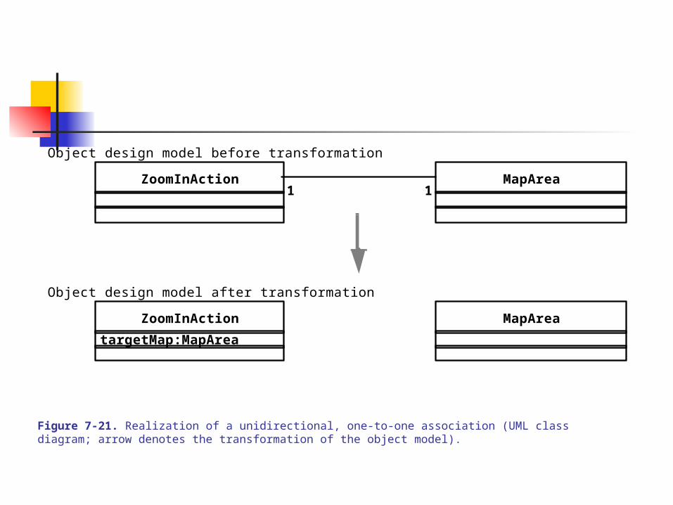
Figure 7-21. Realization of a unidirectional, one-to-one association (UML class diagram; arrow denotes the transformation of the object model).
MapAreaZoomInAction11
MapAreaZoomInAction
targetMap:MapArea
Object design model before transformation
Object design model after transformation
7.0 OBJECT DESIGN
7.4 Object Design Activities – 17
Case 2: Bidirectional, One-to-One Assocation
a. Suppose, by clicking on the left and right buttons, a MapArea object can be zoomed in/outb. This allows a MapArea object to reference a ZoomInAction control object, which is achieved via the attribute: (private) –zoomIn:ZoomInAction c. The ZoomInAction class retains a (private) –targetMap:MapArea attribute for ref to MapAread. Both classes now need methods to exercise the behaviors (‘get’ of object and ‘set’ of it)
7.0 OBJECT DESIGN
7.4 Object Design Activities – 18
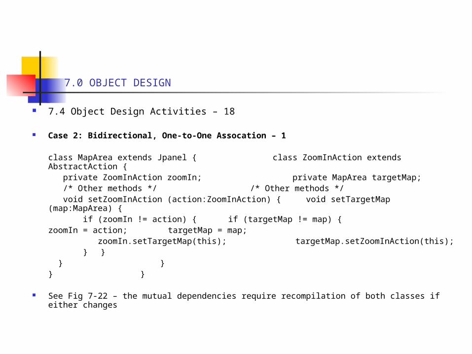
Case 2: Bidirectional, One-to-One Assocation – 1
class MapArea extends Jpanel { class ZoomInAction extends AbstractAction { private ZoomInAction zoomIn; private MapArea targetMap; /* Other methods */ /* Other methods */ void setZoomInAction (action:ZoomInAction) { void setTargetMap (map:MapArea) { if (zoomIn != action) { if (targetMap != map) {
zoomIn = action; targetMap = map; zoomIn.setTargetMap(this); targetMap.setZoomInAction(this); } } } }} }
See Fig 7-22 – the mutual dependencies require recompilation of both classes if either changes
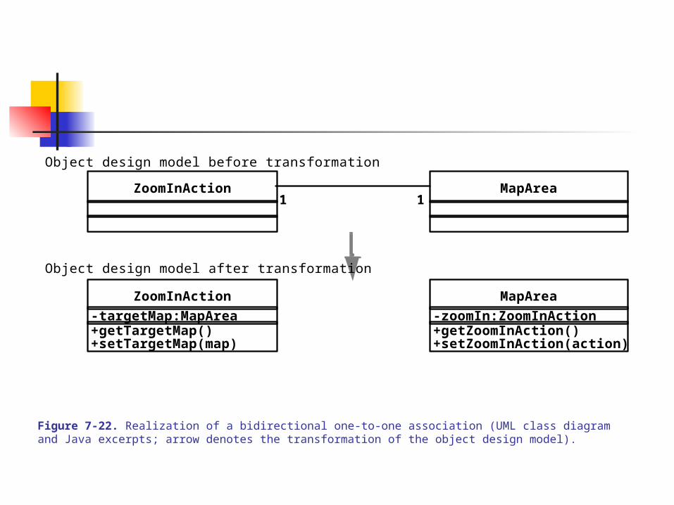
Figure 7-22. Realization of a bidirectional one-to-one association (UML class diagram and Java excerpts; arrow denotes the transformation of the object design model).
MapAreaZoomInAction11
MapAreaZoomInAction
-targetMap:MapArea -zoomIn:ZoomInAction+getZoomInAction()+setZoomInAction(action)
+getTargetMap()+setTargetMap(map)
Object design model before transformation
Object design model after transformation
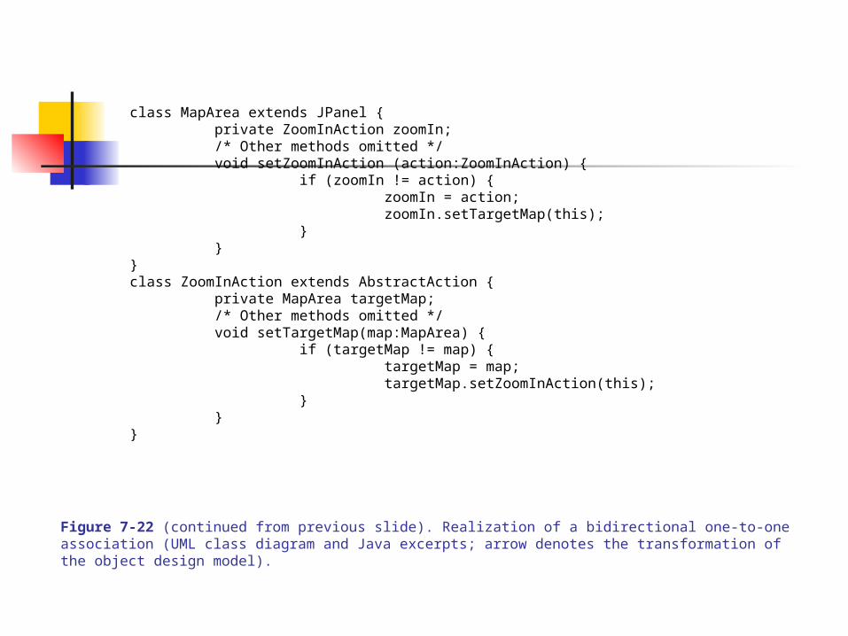
Figure 7-22 (continued from previous slide). Realization of a bidirectional one-to-one association (UML class diagram and Java excerpts; arrow denotes the transformation of the object design model).
class MapArea extends JPanel {private ZoomInAction zoomIn;/* Other methods omitted */void setZoomInAction (action:ZoomInAction) {
if (zoomIn != action) {zoomIn = action;zoomIn.setTargetMap(this);
}}
}class ZoomInAction extends AbstractAction {
private MapArea targetMap;/* Other methods omitted */void setTargetMap(map:MapArea) {
if (targetMap != map) {targetMap = map;targetMap.setZoomInAction(this);
}}
}
7.0 OBJECT DESIGN
7.4 Object Design Activities – 19
Case 3: Bi-directional, One-to-Many Association
a. The 1-end is realized by a reference and the *-end as a collection of referencesb. The LayerElements are un-ordered (simple list or ‘Set’) of elements of Layer. [For ordered elements, an array or Vector type for the ref-attribute will be necessary.]
See Fig 7-23
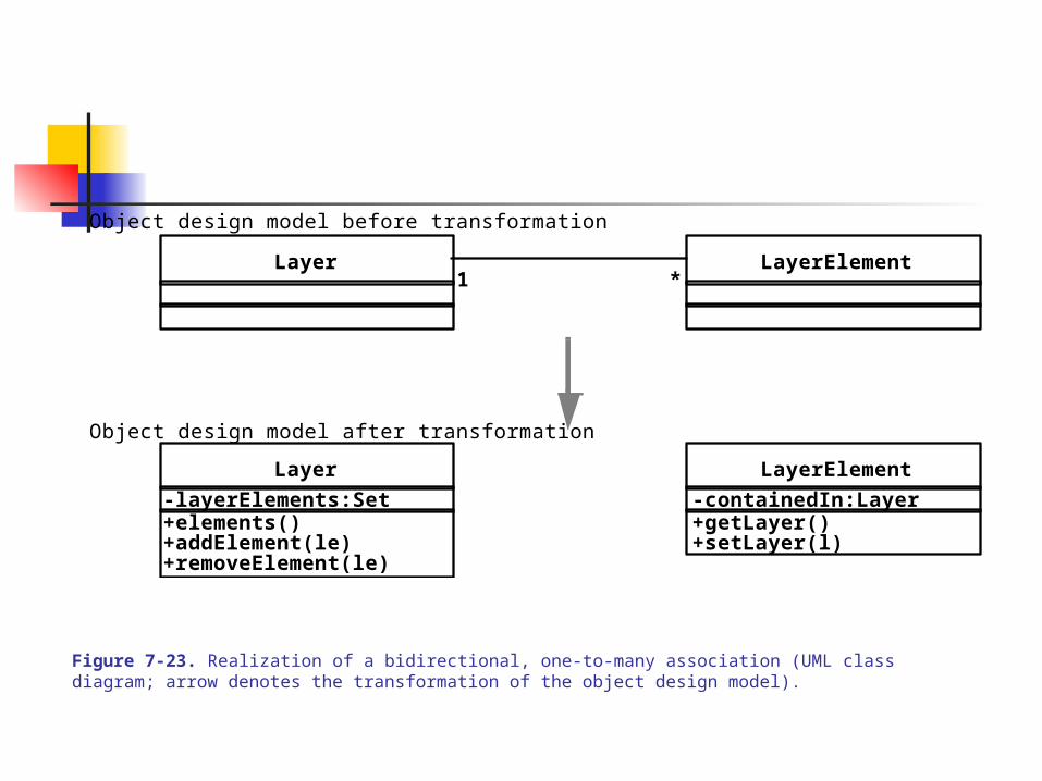
Figure 7-23. Realization of a bidirectional, one-to-many association (UML class diagram; arrow denotes the transformation of the object design model).
Layer LayerElement1 *
Layer LayerElement
-containedIn:Layer-layerElements:Set+elements()+addElement(le)
+getLayer()+setLayer(l)
+removeElement(le)
Object design model before transformation
Object design model after transformation
7.0 OBJECT DESIGN
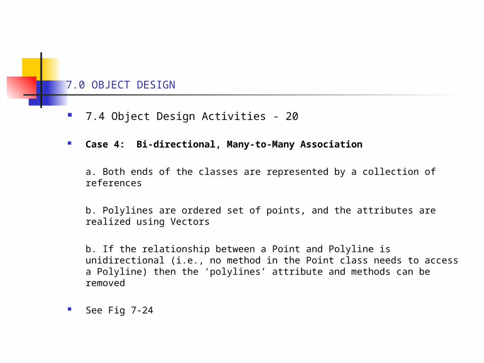
7.4 Object Design Activities - 20
Case 4: Bi-directional, Many-to-Many Association
a. Both ends of the classes are represented by a collection of references
b. Polylines are ordered set of points, and the attributes are realized using Vectors
b. If the relationship between a Point and Polyline is unidirectional (i.e., no method in the Point class needs to access a Polyline) then the ‘polylines’ attribute and methods can be removed
See Fig 7-24
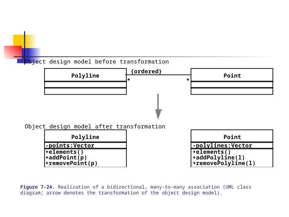
Figure 7-24. Realization of a bidirectional, many-to-many association (UML class diagram; arrow denotes the transformation of the object design model).
Polyline Point* *
Polyline
-points:Vector+elements()+addPoint(p)+removePoint(p)
Object design model before transformation
Object design model after transformation
Point
-polylines:Vector+elements()+addPolyline(l)+removePolyline(l)
{ordered}
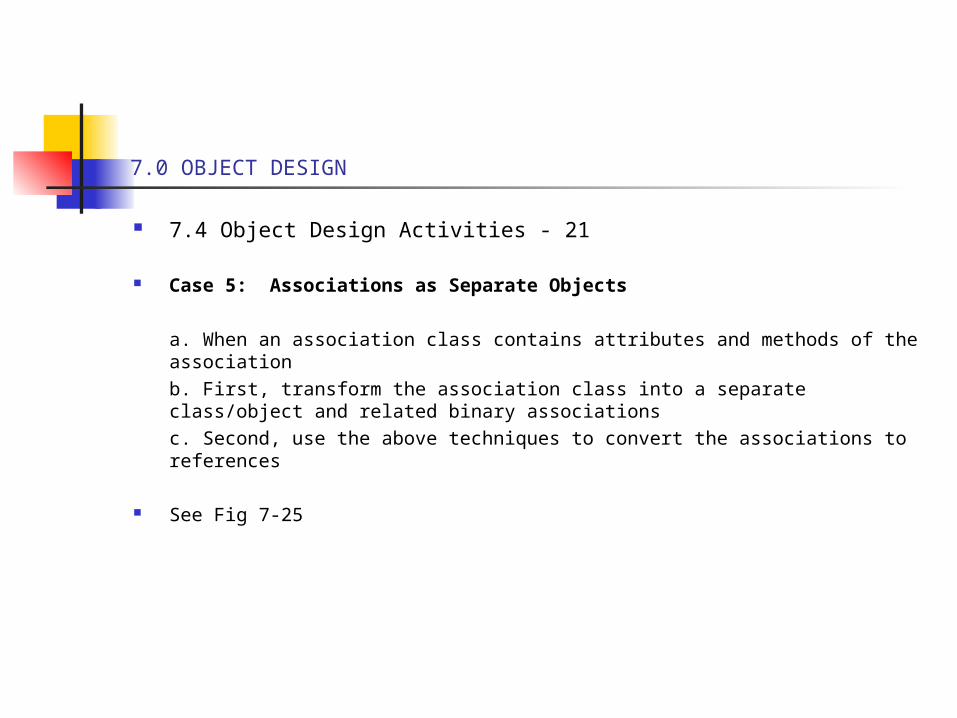
7.0 OBJECT DESIGN
7.4 Object Design Activities - 21
Case 5: Associations as Separate Objects
a. When an association class contains attributes and methods of the associationb. First, transform the association class into a separate class/object and related binary associationsc. Second, use the above techniques to convert the associations to references
See Fig 7-25
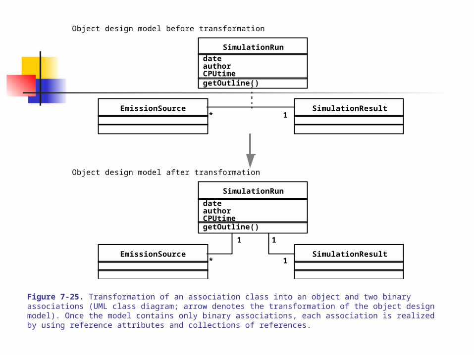
Figure 7-25. Transformation of an association class into an object and two binary associations (UML class diagram; arrow denotes the transformation of the object design model). Once the model contains only binary associations, each association is realized by using reference attributes and collections of references.
SimulationRun
dateauthorCPUtimegetOutline()
EmissionSource SimulationResult* 1
EmissionSource SimulationResult* 1
Object design model before transformation
Object design model after transformation
SimulationRun
1 1
dateauthorCPUtimegetOutline()
7.0 OBJECT DESIGN
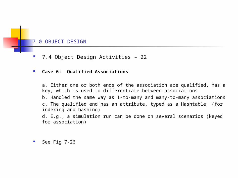
7.4 Object Design Activities – 22
Case 6: Qualified Associations
a. Either one or both ends of the association are qualified, has a key, which is used to differentiate between associationsb. Handled the same way as 1-to-many and many-to-many associationsc. The qualified end has an attribute, typed as a Hashtable (for indexing and hashing)d. E.g., a simulation run can be done on several scenarios (keyed for association)
See Fig 7-26
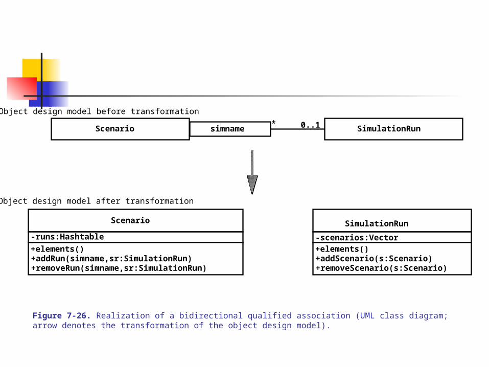
Figure 7-26. Realization of a bidirectional qualified association (UML class diagram; arrow denotes the transformation of the object design model).
Scenario
-runs:Hashtable
+elements()+addRun(simname,sr:SimulationRun)+removeRun(simname,sr:SimulationRun)
SimulationRun
-scenarios:Vector+elements()+addScenario(s:Scenario)+removeScenario(s:Scenario)
simname 0..1*
Object design model before transformation
Object design model after transformation
Scenario
SimulationRun
7.0 OBJECT DESIGN
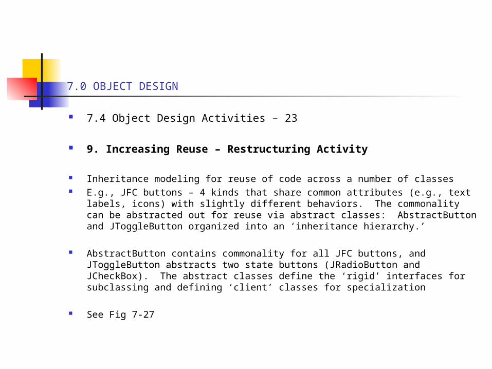
7.4 Object Design Activities – 23
9. Increasing Reuse – Restructuring Activity
Inheritance modeling for reuse of code across a number of classes E.g., JFC buttons – 4 kinds that share common attributes (e.g., text labels, icons)
with slightly different behaviors. The commonality can be abstracted out for reuse via abstract classes: AbstractButton and JToggleButton organized into an ‘inheritance hierarchy.’
AbstractButton contains commonality for all JFC buttons, and JToggleButton abstracts two state buttons (JRadioButton and JCheckBox). The abstract classes define the ‘rigid’ interfaces for subclassing and defining ‘client’ classes for specialization
See Fig 7-27
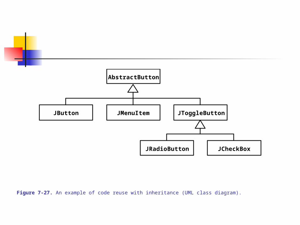
Figure 7-27. An example of code reuse with inheritance (UML class diagram).
AbstractButton
JButton JMenuItem JToggleButton
JRadioButton JCheckBox
7.0 OBJECT DESIGN
7.4 Object Design Activities – 24
9. Increasing Reuse – Restructuring Activity – 1
To reduce the ‘rigidity’ of abstract class interfaces for reuse, we design to decouple client classes from an anticipated changes via level(s) of abstraction – use the Abstract Factory
See Fig 7-28
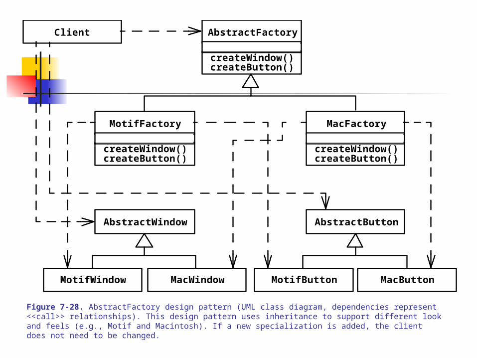
Figure 7-28. AbstractFactory design pattern (UML class diagram, dependencies represent <<call>> relationships). This design pattern uses inheritance to support different look and feels (e.g., Motif and Macintosh). If a new specialization is added, the client does not need to be changed.
AbstractFactory
AbstractWindow
createWindow()createButton()
MotifWindow MacWindow
MacFactory
createWindow()createButton()
MotifFactory
createWindow()createButton()
AbstractButton
MotifButton MacButton
Client
7.0 OBJECT DESIGN
7.4 Object Design Activities - 25
10. Removing Implementation Dependencies – Restructuring Activity
Generalization with inheritance allows reuse of attributes and operations at higher levels
Abstraction (for inheritance) reduces dependencies between the applic and specifics, but generally introduces dependencies ‘along’ all levels in the hierarchy
Generalization with inheritance versus ‘delegation’ to remove hierarchical dependencies
Implementation Inheritance – for the sole purpose of reuse code quickly via subclassingDirect implementation inheritance is improved by delegation – a class delegates (sends a message) to another to effect implementation
(See Fig 7-29: left code is direct inheritance and the right code is via delegation)
Interface Inheritance – for the sole purpose of specialization-generalization hierarchies to manage complexity arising from a large number of concepts via subtyping
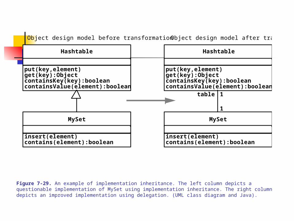
Figure 7-29. An example of implementation inheritance. The left column depicts a questionable implementation of MySet using implementation inheritance. The right column depicts an improved implementation using delegation. (UML class diagram and Java).
Hashtable
MySet
insert(element)contains(element):boolean
put(key,element)get(key):ObjectcontainsKey(key):booleancontainsValue(element):boolean
Object design model before transformation Object design model after transformation
Hashtable
MySet
insert(element)contains(element):boolean
put(key,element)get(key):ObjectcontainsKey(key):booleancontainsValue(element):boolean
table 1
1
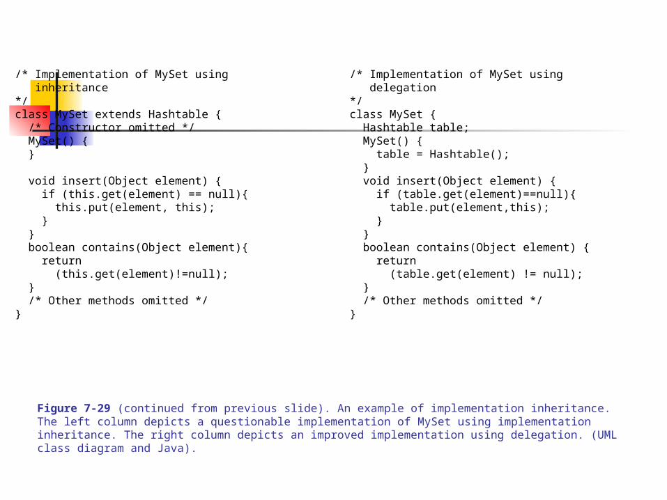
Figure 7-29 (continued from previous slide). An example of implementation inheritance. The left column depicts a questionable implementation of MySet using implementation inheritance. The right column depicts an improved implementation using delegation. (UML class diagram and Java).
/* Implementation of MySet using inheritance*/class MySet extends Hashtable { /* Constructor omitted */ MySet() { }
void insert(Object element) { if (this.get(element) == null){ this.put(element, this); } } boolean contains(Object element){ return (this.get(element)!=null); } /* Other methods omitted */}
/* Implementation of MySet using delegation*/class MySet { Hashtable table; MySet() { table = Hashtable(); } void insert(Object element) { if (table.get(element)==null){ table.put(element,this); } } boolean contains(Object element) { return (table.get(element) != null); } /* Other methods omitted */}
7.0 OBJECT DESIGN
7.4 Object Design Activities – 26
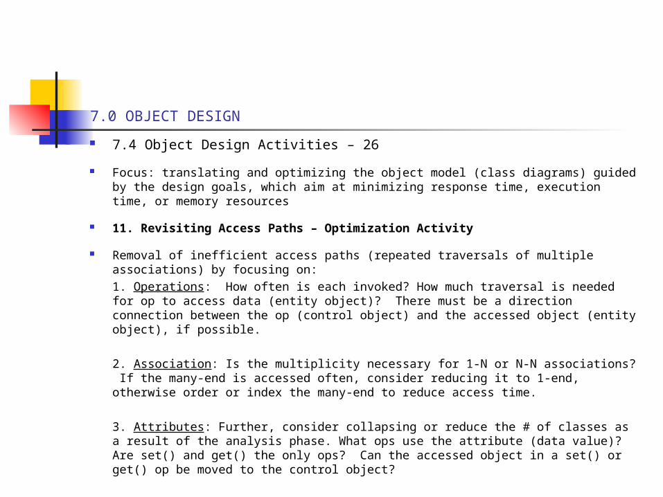
Focus: translating and optimizing the object model (class diagrams) guided by the design goals, which aim at minimizing response time, execution time, or memory resources
11. Revisiting Access Paths – Optimization Activity
Removal of inefficient access paths (repeated traversals of multiple associations) by focusing on:1. Operations: How often is each invoked? How much traversal is needed for op to access data (entity object)? There must be a direction connection between the op (control object) and the accessed object (entity object), if possible.
2. Association: Is the multiplicity necessary for 1-N or N-N associations? If the many-end is accessed often, consider reducing it to 1-end, otherwise order or index the many-end to reduce access time.
3. Attributes: Further, consider collapsing or reduce the # of classes as a result of the analysis phase. What ops use the attribute (data value)? Are set() and get() the only ops? Can the accessed object in a set() or get() op be moved to the control object?
7.0 OBJECT DESIGN
7.4 Object Design Activities – 27
12. Collapsing Objects: Turning Objects into Attributes – Optimization Activity
Many more classes, sometime redundant ones, are included in object models during analysis. System design and object design reduce redundancy via restructuring of the object model.
When restructuring results in classes with fewer attributes or behaviors, collapse them into attributes (to reduce complexity)
(See Fig 7-30 – converting the SS class into an attribute of the Person class)
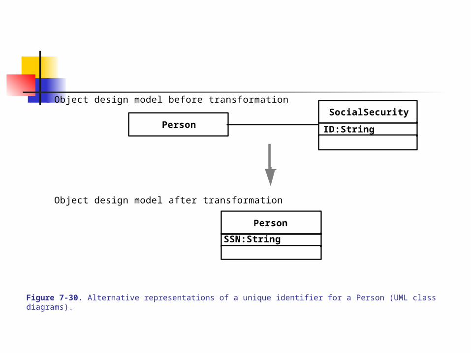
Figure 7-30. Alternative representations of a unique identifier for a Person (UML class diagrams).
PersonSocialSecurity
ID:String
Person
SSN:String
Object design model before transformation
Object design model after transformation
7.0 OBJECT DESIGN
7.4 Object Design Activities – 28
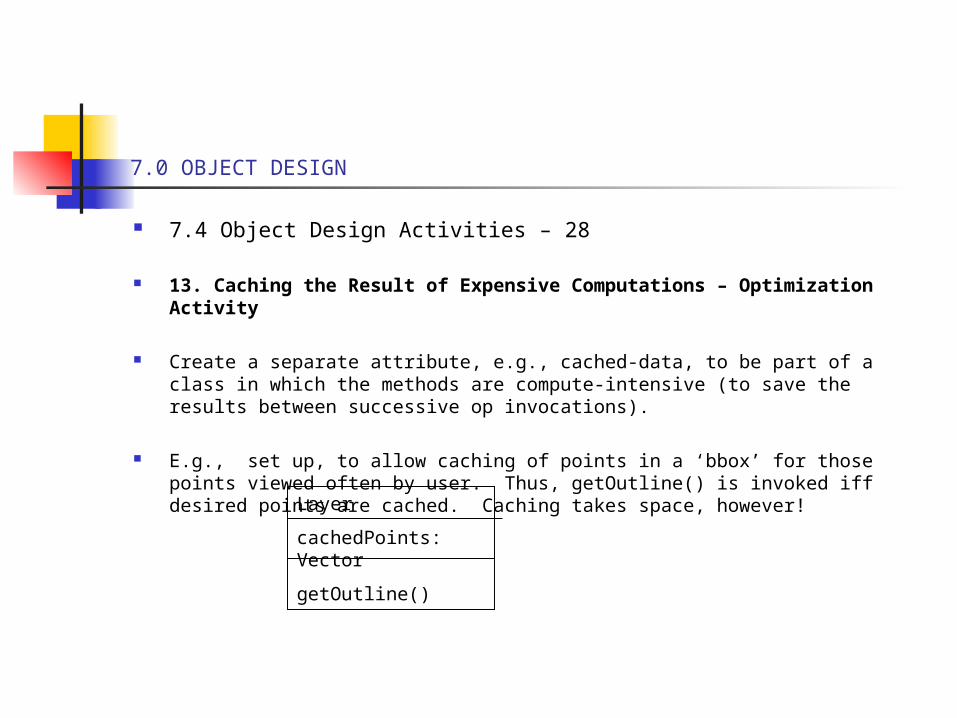
13. Caching the Result of Expensive Computations – Optimization Activity
Create a separate attribute, e.g., cached-data, to be part of a class in which the methods are compute-intensive (to save the results between successive op invocations).
E.g., set up, to allow caching of points in a ‘bbox’ for those points viewed often by user. Thus, getOutline() is invoked iff desired points are cached. Caching takes space, however! Layer
cachedPoints: Vector
getOutline()
7.0 OBJECT DESIGN
7.4 Object Design Activities – 29
14. Delaying Expensive Computations – Optimization Activity
Delaying expensive computations (more than caching does) is to use the Proxy pattern
E.g., to display an image, the actual pixel data need not be loaded until the image is rendered.
The Proxy handles the preparatory work (e.g., compute image size, height, width) and has similar behavior as the RealClass, which the proxy abstracts or interface for.
The Proxy will contain an op/method which activates the RealOp when the real calculation needs to be performed. E.g., when paint() is activated then pixel data is moved and the Real paint() op is executed.
(See Fig 7-31)
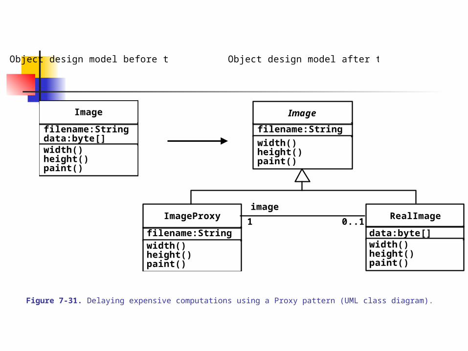
Figure 7-31. Delaying expensive computations using a Proxy pattern (UML class diagram).
Object design model before transformation
Image
filename:String
width()height()paint()
data:byte[]
Object design model after transformation
Image
filename:String
width()height()paint()
RealImage
width()height()paint()
data:byte[]
ImageProxy
filename:Stringwidth()height()paint()
image
1 0..1