Embed Size (px)
Citation preview
CHAPTER XII
Experiments and materials for the study of sound
Children will find fundamental principles and elementary experiments in this chapter on sound
interesting and closely related to everyday experiences.
A. HOW SOUND IS PRODUCED AND TRANSMITTED
1 Different sounds
Exercise on naming different sounds from experiments, if possible, such as crash (dish falls and breaks),
thud (falling weight), clang (beating sheet of iron with hammer), clatter (falling tin cans), crackle (damp wood
on fire), tick (clock), crunch (stepping on gravel), splash (stone falls into water), pop (toy gun), boom
(drum), bang (door), patter (rain drops on pavement), tramp (feet), rustle (leaves), rattle (thunder, snake),
rumble (far-off thunder; thunder rattles, crashes and rumbles) buzz (bee), tinkle (hitting spoon against
drinking glass), neigh (horse), bleat (sheep), cackle or cluck (hen), low (cattle), chirp (bird), hiss (airplane),
whistle, moan, etc.
Children will have fun imitating these sounds. Help them to find the exact definitions in dictionaries.
2 Vibrating bodies produce sound
Tie a loop of stout string in a hole near one end of a ruler. Hold the loop with the fingers. Swing the ruler in
a vertical circle. Whirl it faster. What sound is produced? Repeat the same experiment with different sizes of
rulers and loops. To make it easier, use another ruler or a wood rod instead of your fingers.
3 Say ‘Ah’. Prolong it and feel your wind- pipe. What causes the vibrations? Again feel it when you are
speaking, singing and whistling.
4 Place a ruler on a table so that about three-quarters of it juts out from the table edge. Now hold down
the end on the table with your hand. Bend the other end and let go quickly. The ruler vibrates up and down.
Note what sound you hear. Again place the ruler so that half juts out from the table edge. Repeat the
experiment. Note the sound you hear again. Is it different from the last one? Repeat the experiment with
different lengths of the ruler jutting out from the table edge.
From these experiences one may conclude that sound is produced by vibrations. The vibrating bodies set
up vibrations in the air which strike your ear, and you hear a sound.
5 Meaning of a vibrating object
Secure a small, heavy object, such as a piece of lead or iron or a small ink bottle. Tie the object with one
end of a string about 1-m in length. Now set up a pendulum by hanging the object from the top of a
doorway with the other end of the string. Let the object swing freely like a pendulum. How many swings will
it make in one minute? Take many more counts with shorter lengths of string. You will note that shortening
the string makes the object swing faster.
Also observe the vibration of a children’s swing.
Secure a pendulum clock and a metronome, or a musician’s time-piece. Make a study of rates of
vibrations with these instruments. Imagine that an object vibrates faster and faster; beyond 16 times per
second the surrounding air will be set into vibration, and a very low note will be heard. Higher notes are
produced from faster vibrations, up to about 20,000 times per second, which is the highest note man can
hear.
Also see Chapter XI, experiments B 3-5.
6 Run a toy car with a siren. The faster it runs, the higher the note it produces.
7 Blow across the mouth of an empty bottle. Try the same experiment with different-sized bottles.

8 Now replace the vibrating human lips in the last experiment by the wing top of a burner. Air blown through
the wing top will pass the opening with great speed and spread out flat lile a broad flame. The resonating
sounds produced depend on the vibrating air columns in bottles or tubes. Adjust the position of the wing top
so that the air stream produces the loudest sound. You will hear the lowest note from a fairly big bottle or a
paper mailing tube, up to the highest audible note from the end hole of a very small key.
9 Sympathetic bottles
Have a pupil hold the mouth of one bottle close to his ear without obstructing the opening. Now blow
strongly across the mouth of another similar bottle until you produce a strong, clear note. Every time you do
this, resonant vibrations are set up in the second bottle. These produce a weaker, though similar, note which
your pupil can hear distinctly.
10 Secure a tuning fork and a used petroleum tin can, a violin or any wood box as a sound box. Set the
fork into vibration by hitting it against a block of wood. Then press its handle against the sound box. You will
hear a very loud humming sound from the box. Repeat the experiment with a dinner fork.
11 Air carries sound
Let one person whistle; other persons in the same room will hear the sound distinctly. Now send the first
person into another room, and let him whistle again; it will no longer be possible to hear him distinctly.
12 Sound cannot travel through a vacuum
Make a vacuum pump and receiver (Chapter VII, experiment I 3).
Tie two small bells inside the vacuum receiver. Start the experiment by shaking the receiver with air inside;
you will hear the bells ringing. Then screw in the cap tightly, suck the air out of the receiver with the pump.
Shake the receiver again; you will not hear the ringing of the bells as clearly as before. What does this
mean?
Repeat the experiment, but create the vacuum by burning pieces of paper in the receiver.
13 Take a long garden hose, open at both ends. Use it as a telephone line for talking and listening to
another person. Air inside the hose is the carrier of sound. The principle is still applied within a ship for
speaking from one quarter to another.
14 Solids carry sound
Secure two used tin cans with lids neatly cut out. Now punch a small hole in the centre of the bottom of
each tin can. Thread several metres of a thin cotton string through the holes. Attach a matchstick at each end
of the string so that the matchsticks cannot go through the holes. Now use the cans as telephones: get the
string taut and talk and listen to your pupil. Sound travels through the string and through the air inside the tin
cans. The bottom part of the tin acts as a diaphragm.
This experiment can also be performed with two empty matchboxes, one side of each being covered
tightly with thin pieces of transparent cigarette wrapper paper. The holes may be punched in the paper.
15 Church bell from a spoon
Cut one metre of a cotton cord. With both ends together,
balance a teaspoon in the loop. Now hold each end with
your fingertips. Press both ends to your ears and bend
down so that the string and spoon hang freely. Let some-
one hit the spoon lightly with a nail or another spoon. You
will hear a chime like that of a church bell. Again sound
travels right up the string, ending in your ears.

16 Tapping codes through water pipes
Send a code message made up by a pupil and yourself through a water pipe that goes from one room to
another on the same floor or on different floors. By striking the water pipe with a piece of iron in one room
the sound reaches your pupil in the other. Then interchange messages. Sound travels through the water pipe
this time.
17 Hear through your teeth
Set a fork or a tuning fork into vibration. Wait until you cannot hear any sound from the fork, then place
the handle between your teeth. The sound will still be heard. Repeat the experiment by placing the handle on
the bone at the back of your ear.
18 Liquids carry sound
Place your head under a pool of water so that your ears are immersed. (It may be in a swimming pool, the
sea, a river or even a bath tub.) Let somebody else strike a gong or a bell under the water away from you,
while your ears are still under water. You will hear the sound coming through the water clearly. It is a fact
that sound travels about four times as fast under water as through air.
19 Gas balloon acts as a sound lens
Fill a rubber balloon with air by blowing into it with your mouth until it expands to normal size. Hold the
balloon with your fingers. Now the balloon is partly filled with carbon dioxide gas. Hold the balloon
between your ear and a watch. You will hear the sound of ticking more clearly than without the balloon. This
is because sound waves travel more slowly through heavy carbon dioxide gas than they do through air. The
balloon acts as a con- verging lens to sound waves. Repeat the experiment with a balloon full of hydrogen
gas.
20 How waves travel
The way in which energy is carried by waves can be studied by observing how they travel along the
surface of water. They can often be seen in lakes, ponds and harbours, and the patterns produced help to
explain many of the phenomena of light and radio, as well as of sound.
A more detailed examination of this behaviour can be made in the laboratory by producing ripples on the
surface of a shallow dish of water. One way of making the patterns more visible is to place a source of light
underneath a shallow tank with a glass bottom. Ripples produced in such a tank behave as cylindrical
lenses, and shadows are seen on the ceiling or a screen placed above.
21 Making a ripple tank
Cut a rectangular aperture in the bottom of a photographic developing dish of full plate size, leaving a rim
about 2.5 cm wide all round. Fit a sheet of clear glass to the tank and stick it down to the rim using a
waterproof glue. Set it aside to dry. Obtain a cardboard box about 30 x 30 x 45 cm in size. Cut a circular
hole L5 cm in diameter in the middle of one of the smaller faces, and make a small door in the middle of one
of the rectangular sides. Paint the inside of this box a dull black. As a point source of light fit a car bulb and
holder to a cube of wood of 7.5 cm side.
Stand the tank over the circular aperture in the box, and pour in water to a depth of about 1 cm. Darken
the room and switch on the bulb. Observe the circular pattern produced on the ceiling when a drop of water
falls into the water from a pen filler or pipette. If the pattern is distorted by the action of waves reflected
from the sides of the tank, fit sloping beaches of picture frame moulding in the water all round the edges.
Should there be patterns parallel to the sides caused by vibration of the tank as a whole, stand it on strips of
‘sorbo’ robber or felt.
Continuous trains of waver can be produced by a vibrator with one end dipping into the water. Clamp a
30 cm hacksaw blade in the middle and attach a single piece of stout copper wire to one end, using an
electrical terminal or a small bolt. Bend the wire at right angles to the plane of the blade and cut it off about
2.5 cm long. Support the blade in a firm retort stand so that the end of the copper wire dips into the water in
the tank. Pluck the free end of the blade, and notice the generation of continuous waves.
Cut a T-shaped piece of tin to form a dipper for plane waves and attach it to the free end of the blade as
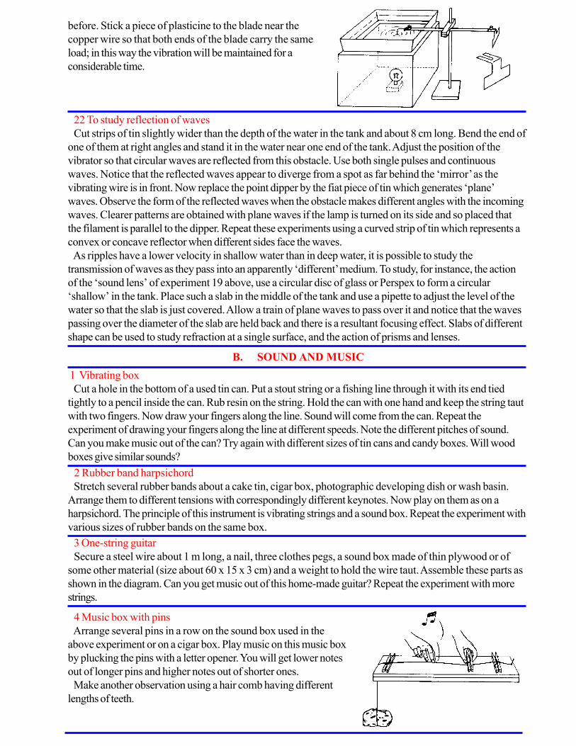
before. Stick a piece of plasticine to the blade near the
copper wire so that both ends of the blade carry the same
load; in this way the vibration will be maintained for a
considerable time.
22 To study reflection of waves
Cut strips of tin slightly wider than the depth of the water in the tank and about 8 cm long. Bend the end of
one of them at right angles and stand it in the water near one end of the tank. Adjust the position of the
vibrator so that circular waves are reflected from this obstacle. Use both single pulses and continuous
waves. Notice that the reflected waves appear to diverge from a spot as far behind the ‘mirror’ as the
vibrating wire is in front. Now replace the point dipper by the fiat piece of tin which generates ‘plane’
waves. Observe the form of the reflected waves when the obstacle makes different angles with the incoming
waves. Clearer patterns are obtained with plane waves if the lamp is turned on its side and so placed that
the filament is parallel to the dipper. Repeat these experiments using a curved strip of tin which represents a
convex or concave reflector when different sides face the waves.
As ripples have a lower velocity in shallow water than in deep water, it is possible to study the
transmission of waves as they pass into an apparently ‘different’ medium. To study, for instance, the action
of the ‘sound lens’ of experiment 19 above, use a circular disc of glass or Perspex to form a circular
‘shallow’ in the tank. Place such a slab in the middle of the tank and use a pipette to adjust the level of the
water so that the slab is just covered. Allow a train of plane waves to pass over it and notice that the waves
passing over the diameter of the slab are held back and there is a resultant focusing effect. Slabs of different
shape can be used to study refraction at a single surface, and the action of prisms and lenses.
B. SOUND AND MUSIC
1 Vibrating box
Cut a hole in the bottom of a used tin can. Put a stout string or a fishing line through it with its end tied
tightly to a pencil inside the can. Rub resin on the string. Hold the can with one hand and keep the string taut
with two fingers. Now draw your fingers along the line. Sound will come from the can. Repeat the
experiment of drawing your fingers along the line at different speeds. Note the different pitches of sound.
Can you make music out of the can? Try again with different sizes of tin cans and candy boxes. Will wood
boxes give similar sounds?
4 Music box with pins
Arrange several pins in a row on the sound box used in the
above experiment or on a cigar box. Play music on this music box
by plucking the pins with a letter opener. You will get lower notes
out of longer pins and higher notes out of shorter ones.
Make another observation using a hair comb having different
lengths of teeth.
3 One-string guitar
Secure a steel wire about 1 m long, a nail, three clothes pegs, a sound box made of thin plywood or of
some other material (size about 60 x 15 x 3 cm) and a weight to hold the wire taut. Assemble these parts as
shown in the diagram. Can you get music out of this home-made guitar? Repeat the experiment with more
strings.
2 Rubber band harpsichord
Stretch several rubber bands about a cake tin, cigar box, photographic developing dish or wash basin.
Arrange them to different tensions with correspondingly different keynotes. Now play on them as on a
harpsichord. The principle of this instrument is vibrating strings and a sound box. Repeat the experiment with
various sizes of rubber bands on the same box.

5 Drinking straw orchestra
Secure 10 drinking straws for five players and a pair of scissors. Flatten one end of a straw and cut both
corners of this hat end. Now this flat end acts as the reed of a wind instrument. Blow into it and adjust the
reed until you get the best vibrations.
Next, set up an orchestra by making similar reeds out of other drinking straws. Cut off the other ends of
the straws bit by bit to tune with different musical notes until you get a complete scale. Each of the five
players is responsible for two notes, holding a straw in each hand. To begin with, try to play your National
Anthem.
The principle is that the air column inside the straw vibrates because of the vibrating reed.
6 Bottle and glass tube trombone
Secure a glass or metal tube about 1 cm in diameter and 20 cm in length, and a bottle nearly full of water.
Hold the bottle in one hand and the glass tube in the other, with the end of the tube dipping in the water.
Now blow across the other end of the tube for a note. Next, as you blow, move the bottle up and down.
You will hear various notes as you change the length of the column of air vibrating in the tube.
7 Musical bottles
Prepare a set of musical bottles so that each contains an air column tuned to one of the notes of the scale.
Select eight similar bottles. Let the first one be empty. If water is added to the others to the proper heights,
when they are tapped with a ruler or chopstick they will sound out a complete musical scale. You can do the
same experiment with tall drinking glasses. The air columns inside the bottles or glasses take up vibrations
from the outsides.
It is fun also, if you happen to possess china vases or bells of many sizes. Pick out those which are tuned
to notes of the scale. Arrange them in a row. Hold a chopstick or a fork in each hand and carefully beat out
a tune on them.
8 A set of dinner chimes
Secure a straight steel pipe about 3 cm in diameter and about 3.5 m in length. Cut it into four parts, 100
cm, 90 cm, 80 cm and 70 cm. Drill holes through both sides of each pipe near one end, and suspend them.
Let them hang freely. Strike each pipe in turn with a rubber hammer and compose a sort of signature chime
for your class.
9 Cigar box violin
Procure a cigar box or any similar box, regular strings from a
music supply store, bits of wood, a piece of resin and cotter pins.
Try to assemble these parts yourself so as to make the cigar box
violin shown in the figure. The bow may be made from horsehair
and a twig about 70 cm in length.
10 Shepherd’s pipe
A section of bamboo is suitable for the pipe. Secure a
straight bamboo about 1.5 cm in diameter and 30 cm in
length, open at both ends and all through its length. Dry it by
roasting on a small fire until its skin turns a yellowish brown all
over. When it cools, make the mouthpiece and row of holes
as shown in the figure. The pipe is similar to a tin whistle but
the sound obtained is sweeter. The air column vibrated is
measured from the exit hole in the mouthpiece to the first
uncovered hole.
Cotter PinTwig
Horse Hair

11 Xylophone and marimba
What you need here are strips of hard wood, bamboo, or iron, and a
board; 8, 12 or 16 of these strips, cut to the proper lengths to sound out
the scale when tapped, are required. For pieces of hardwood 2.5 cm wide
and 1 cm thick, lengths of 20.0, 22.8, 24.2, 25.8, 27.2, 28.3, 29.5, 30.5
cm will give the diatonic scale. For the fiat board of the xylophone, drill a
hole about 2 mm in diameter near the end of each strip. Lay strips of felt
on the board and drive small nails through each hole to hold the strips
loosely. The strips will vibrate when tapped with a rubber hammer. This
can be made from a pencil and a piece of eraser.
For the marimba, pieces of wood are shaped, as shown in the figure, to
form the base and act as a sound box. Drill two holes near the end of each
strip. Put a stout string through aid the holes as shown and suspend the
strips over the box.
Now procure two rubber hammers with rather long handles. Tap the
strips lightly to obtain music.
Other simple musical instruments can be constructed, e.g., a variety of
drums, scale of small gongs, flutes and many string instruments. Try to
devise them yourself.
C. RECORDING AND REPRODUCING SOUND
1 How the ear works
Air vibrations enter the ear by the auditory passage formed at the
base of the ear by the ear-drum membrane. They set the ear-drum
in motion and, in doing so, set in motion the system of three little
bones attached to it; by this means they reach a cavity in the bone
called the inner ear.
One part of the ear is shaped like a snail shell. Here is found the
organ which receives the sound vibrations and is connected with the
brain by the auditory nerve. Another part of the inner ear which
includes three small semicircular canals and serves to maintain
equilibrium plays no part in hearing.
2 How the voice is produced
Mouth, teeth, tongue, throat and lungs are all used in the production of
the voice. The sound is produced by vibrations of two thin sheets of
membrane called the vocal cords, which are stretched across the sound
chamber called the larynx. The larynx is the upper end of the windpipe and
is located well back, at the base of the tongue. Here a trap door of
cartilage called the epiglottis automatically drops down over the larynx
when you swallow, so that no food will go through the windpipe. When the
cords are stretched by the contraction of certain muscles in the throat, a
narrow slit tends to form between them. It is when the air is forced through
this narrow slit that the cords are forced to vibrate. This sets the air
vibrating in the windpipe, lungs, mouth and nasal cavities.
Sound vibrations are normally transmitted to the snail-shell-shaped cochlea by the ear- drum and the small
bones (this gives rise to a nerve message which is carried to the brain); but they can also be transmitted by
the bones of the skull, and we hear a sound if the waves reach the cochlea by either route.
When a sound reaches our two ears, we can distinguish the direction from which it comes; if it comes
from straight ahead, the vibrations reach both ears at the same time and with the same strength; but if the
source of the sound is on one side of us, one of our ears is farther away from it and receives the waves less
strongly and with a slight delay.
Ear drum
vibratesHammer
and Anvil
Auditory
Nerve
Middle Ear Inner EarOuter Ear
Vocal cords Epiglotis
Ordinary
Breathing Larynx
Speaking

3 Sound wave patterns
The number of complete vibrations in one second
is the frequency of a particular vibration. The way
in which different sound frequencies combine is
analogous to water waves. Ocean waves are
longest, i.e. of low frequency. Let a small motor-
boat pass over these waves. The boat sends out its
own waves, which have a shorter frequency than
ocean waves. Next, if there is a breeze, it will send
tiny ripples across the surface of the motor- boat
waves. The ripples usually have an even shorter
frequency than the other two. Now these three
vibrations combine to form a pattern shown in the
figure.
In a similar way, sound waves of different
frequencies from various instruments combine and
form sound wave patterns.
4 Wave pattern of a tuning fork
With a few drops of hot sealing wax attach a piece
of fine wire to the prong of a tuning fork. The fork is
held rigidly by the handle and placed horizontally just
above the table top. Smoke a small pane of glass
from the flame of an oil lamp or a candle. Now lay
the smoked glass pane under the prong with the fine
wire which is bent to touch the glass pane. Start the
vibrations with the finger and draw the pane along the
table fast enough to make a wavy line on the pane.
Repeat this experiment drawing the pane away at
different speeds and using different tuning forks.
The higher the top of the wave from the base line
the louder the sound.
5 A gramophone reproduces sound
Secure a 78 r.p.m. gramophone record and a hand magnifier.
Through the magnifier you will notice a great number of wavy
lines on the record. If possible, compare the wavy lines of
records of different speeds.
Next, set the record turning at its usual speed of rotation. Place
the edge of your finger-nail in the groove and listen carefully. Do
you hear music coming from your nail? Do you feel your nail
vibrate? It is clear that your nail is forced to vibrate as it follows
the grooves, and produce the recorded sounds.
Ocean Wave
Boat Wave
Ripples
Combination
Different
Frequencies
Combining
Pure Note
Sealing Wax
Fine Wire
Smoked Glass Pane
on tablefork vibrating
Drawing Pane fork not vibrating
Drawing Pane fork vibrating Base line

6 A simple reproducer
Thrust a record needle through the corner of a card or an empty
matchbox. Now repeat the last experiment. Let the needle replace
your fingernail. Has the sound been amplified ?
7 Another simple reproducer
For a more effective home-made reproducer you can copy the
early phonographs by using a horn. Substitute for the card or the
match- box a horn made out of a square sheet of heavy wrapping
paper, about 40 x 40 cm.
Shape the paper into a cone and fold the small end. Force a
needle into all thicknesses as indicated in the diagram. Hold the horn
so that the needle will rest lightly in the groove as the record rotates.
Now, everybody in the room should hear the music from your simple
reproducer.
8 A gramophone for everyone
What you need are two circular pieces of wood about 2.5 cm thick, and 30 cm in diameter, a base board
about 80 x 40 x 2.5 cm, a sheet of flannel, 30 cm in diameter, as base, a piece of mica sheet 10 x 10 cm, a
tube of Duco cement, gramophone needles, pins, a metal flange as frame of the reproducer, and an adaptor
for the needle.
Your gramophone will look roughly like the first figure. Mount the two circular pieces of wood on the base
board as illustrated, with the drive wheel and turn-table connected by a suitable length of heavy cotton cord.
The flannel or felt pad is glued to the turn-table as the base for the record.
The important part of the machine, i.e., the reproducer and horn, may be made in one of two ways. The
paper milk container method is the simpler one. Follow the illustration.
(a) Cement a rubber band neatly around the edge of the metal flange upon which the cap normally rests.
(b) Cut a disk from the mica sheet to fit the milk container opening.
Counterpoise
Heavy Cotton
Cord
Heavy Wooden
Wheel
Screw set
in loosely
Turn Table
Flannel Pad
Drive
Wheel

9 Recording of sound by gramophone
Recording is just the reverse process of reproducing. We
have learnt that the voice or any other sound can be used to
cause an object to vibrate and to form wavy lines on a
smoked glass pane in motion.
Hold a card in front of your mouth and utter sounds against
it. Feel the vibrations with your finger tips.
Remove the bottom of an ice-cream cup or a paper milk
container and bind a diaphragm of thin paper or rubber over
the small end. Hum into it and feel the vibrations again.
(c) Drill a small hole at the centre and, after bending
an oversize pin sharply near the head, insert it into the
hole and then through another hole in the metal flange.
Wooden
Pill BoxSpring
CardboardMica
(d) Cement the diaphragm in place with Duco or a quick-drying cement.
(e) For the adaptor, cut a 6 mm length of small brass rod, drill a small hole all the way through and solder
it to the cut-off end of the pin; secure a little set screw and drill a hole in the side a bit smaller than the
threaded part of the screw and then force the screw in by turning it strongly so that it is well secured.
(f) Instead of making the adaptor in (e) you can use a brass electric wire fixer in any old lamp socket as
the adaptor. (g) For the horn, remove the bottom of a wax paper ice-cream cup or a paper milk container,
and fix it in the hole of the metal flange.
Rubber
Band
Sealing
Wax SolderCementMica
Diapragm Vibrates
Card Vibrates
(h) Attach the whole unit to the carrier arm with
adhesive tape, and the rest will be up to you.
The second way of making the reproducer is
illustrated above. This will give you an instrument
more on the lines of a regular gramophone.

Detach the reproducer you made in the last experiment.
Speak into the opening and, while doing so, feel the tip of
the needle vibrating.
Now replace the reproducer and put a smoked glass
disk of about the same diameter as the usual record on
the turn-table. Speak into the horn and at the same time
rotate the turn-table. The vibrating needle point will draw
wavy lines, a record of your voice. A hard-wax circular
sheet might be used in place of a smoked glass disk.
Thomas A. Edison devised the first talking machine,
which was a recorder as well as a reproducer. He first
recorded the sounds and then played them back. If you
are able to visit a science museum, have a look at the old-
fashioned type of dictaphone. The parts are shown more
clearly than in the newer types.
Magnified Section of
Gramophone Record
Needle Arm
Needle Post
Reproducing Point Wax Cylinder
Recording Point
“BE A GOOD SCIENTIST. FOLLOW INSTRUCTIONS EXTREMELY CAREFULLY.
WEAR PROTECTIVE CLOTHING WHEN WORKING ON ANY EXPERIMENTS
THAT INVOLVE FIRE OR EXPLOSIONS.”
Experiments and materials for the study of heat
A. THE EXPANSION EFFECT OF HEAT
CHAPTER XIII
1 Triangle to show expansion on heating
Bend a piece of stiff metal wire into a triangle. Support it
in a horizontal plane and suspend a coin between the two
free ends forming one corner. Heat the opposite side of the
triangle and the coin will fall out.
2 To show the expansion of a solid when heated
Get a piece of stout copper tubing about 2 m long. Lay it on a table and fix
one end by a clamp. Underneath the other end put a piece of bent knitting
needle or bicycle spoke to act as a roller. A thin strip of balsa wood about 1
m long fixed to the roller by sealing wax will show any movement of the rod
resting on it. Blow steadily down the tube at the fixed end, and the expansion
of the tube caused by the hot breath will be detected by this arrangement.
Now pass steam through, and the pointer will make a complete revolution or
more, depending on the diameter of the roller. Repeat the experiment after the
roller and pointer have been moved nearer to the loose end of the rod.
Compare the results.
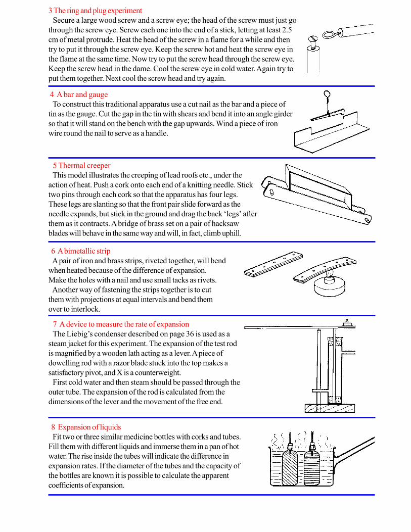
3 The ring and plug experiment
Secure a large wood screw and a screw eye; the head of the screw must just go
through the screw eye. Screw each one into the end of a stick, letting at least 2.5
cm of metal protrude. Heat the head of the screw in a flame for a while and then
try to put it through the screw eye. Keep the screw hot and heat the screw eye in
the flame at the same time. Now try to put the screw head through the screw eye.
Keep the screw head in the dame. Cool the screw eye in cold water. Again try to
put them together. Next cool the screw head and try again.
4 A bar and gauge
To construct this traditional apparatus use a cut nail as the bar and a piece of
tin as the gauge. Cut the gap in the tin with shears and bend it into an angle girder
so that it will stand on the bench with the gap upwards. Wind a piece of iron
wire round the nail to serve as a handle.
5 Thermal creeper
This model illustrates the creeping of lead roofs etc., under the
action of heat. Push a cork onto each end of a knitting needle. Stick
two pins through each cork so that the apparatus has four legs.
These legs are slanting so that the front pair slide forward as the
needle expands, but stick in the ground and drag the back ‘legs’ after
them as it contracts. A bridge of brass set on a pair of hacksaw
blades will behave in the same way and will, in fact, climb uphill.
6 A bimetallic strip
A pair of iron and brass strips, riveted together, will bend
when heated because of the difference of expansion.
Make the holes with a nail and use small tacks as rivets.
Another way of fastening the strips together is to cut
them with projections at equal intervals and bend them
over to interlock.
7 A device to measure the rate of expansion
The Liebig’s condenser described on page 36 is used as a
steam jacket for this experiment. The expansion of the test rod
is magnified by a wooden lath acting as a lever. A piece of
dowelling rod with a razor blade stuck into the top makes a
satisfactory pivot, and X is a counterweight.
First cold water and then steam should be passed through the
outer tube. The expansion of the rod is calculated from the
dimensions of the lever and the movement of the free end.
8 Expansion of liquids
Fit two or three similar medicine bottles with corks and tubes.
Fill them with different liquids and immerse them in a pan of hot
water. The rise inside the tubes will indicate the difference in
expansion rates. If the diameter of the tubes and the capacity of
the bottles are known it is possible to calculate the apparent
coefficients of expansion.

9 Expansion of gases
The medicine bottles can also show the expansion of air or other
gases. Push the glass tube through the cork and trap some air. A
hand placed on the bottle drives liquid up the tube.
A simple form of air thermometer can be made arranging the
tube as shown on the right in the diagram. Also refer to experiment
B2 below.
Warming the bottle causes air to be expelled. This reduces
pressure inside. When the bottle cools liquid is forced up the tube.
10 Expansion of gases—soap bubble
A soap bubble stretched over the neck of a medicine bottle will grow larger if warm hands are placed on
the bottle.
11 Another way to show the expansion of gases
Stretch a rubber balloon over the neck of a flask which has been made from a used electric bulb. Heat the
flask gently with a candle or an alcohol flame.
See also Chapter VIIT, experiment B 2.
12 An expansion experiment with a balloon
Partially inflate a balloon or a basket ball. Hold the balloon or ball over a hot plate or place it in the warm
sun for a while and observe the results.
13 Fire balloon
Make a simple fire balloon from a large paper bag similar to
those used by milliners.
Open out the mouth with a ring of florist’s iron wire having a stay
across the diameter. Fix the ring to the bag with strips of gummed
paper. Tie a small piece of sponge or cotton wool to the middle of
the stay and dip it in methylated spirit. Light the spirit and hold the
bag by the ring. There is danger of setting fire to the paper bag in
this experiment, which is best performed in the open air.
This paper bag balloon is not very stable in flight. A better one
can be made as follows:
Place on a table six sheets of tissue paper, one on top of the
other. Cut them in the shape shown in the figure and stick them
together at the edges to form a balloon. A circular disk will be
needed as cap to close the top. Fix a ring to the neck as before.
Such a balloon will rise to great heights and can be flown from a
piece of string like a kite. Solid methylated spirit, as employed in
some spirit lamps, is easier to use if it can be obtained: it can be
placed on a small tin lid attached to the wire ring at the mouth of the
balloon.

B. TEMPERATURE
1 Is your temperature sense reliable?
Fill three pans with water. Have one at the highest temperature you can bear your hand in. Fill a second
one with ice-cold water. The third should be lukewarm. Put both hands in the lukewarm water and hold
them there for about half a minute. Does the water seem to be the same temperature for both hands? Does
it feel hot, cold or neither?
Next place your left hand in the hot water and your right hand in the icy water for a minute. Quickly dry
your hands and plunge both into the lukewarm water again. How does the right hand feel? How does the
left hand feel? Do they feel the same as when in the lukewarm water before? What do you think about your
temperature sense?
2 Making an air thermometer
Fit a flask made from a used electric bulb (or a thin-walled bottle or test tube) with a
one-hole rubber stopper which has a 60 cm length of glass tubing in it. The stopper must
be an air-tight fit in the bulb. You can seal the stopper in by dropping some wax from a
candle around the joint. Build a support for your thermometer from wood as shown in the
diagram. Paste a strip of paper for a scale behind the tube. Place the lower end of the
tube in a small bottle of cold water, coloured with ink. Heat the bulb of the thermometer
gently to drive out some of the air. Drive out just enough air so that when the bulb cools to
room temperature the coloured water will rise about half way up the tube.
To make your scale, let the thermometer stand in a room for several hours. Have
another thermometer near the bulb. Make a line on the paper at the level of the water and
mark the reading of the thermometer at this point. Next move your thermometer to a
warm place to stand for an hour with the other thermometer near the bulb. Mark the
water level and the temperature. Move again to a cool place and again mark the water
level and temperature. Divide the space between these marks into equal divisions and
mark off the corresponding temperatures.
3 How a thermometer works
Fill a flask made from a used electric light bulb with water that has been coloured with ink. Insert a one-
hole stopper carrying a 30 cm length of glass tubing until the water rises in the tube a distance of 5 or 6 cm.
Place the flask on a tripod over an alcohol burner and observe the water level as you heat it. The water
expands more rapidly than the glass and rises up the tube. Some keen observers in the class may notice that
just at the moment heating is begun, the water level drops and then begins to rise. This is because the glass
bulb starts to expand before the water inside reaches the temperature of the glass.
4 Making a spirit thermometer
To make a simple alcohol thermometer, accurate enough for indicating
variations of temperature, use 20-30 cm of glass tubing of about 5 mm
external diameter with about 1 mm bore. A bulb of about 1.5 cm
external diameter is first blown in one end of the tubing; coloured
industrial alcohol is allowed to enter by means of a rubber tube and a
thistle funnel till the thermometer is filled and without bubbles. The
thermometer is then placed in water at 600 C, which is slightly below
the boiling point of alcohol, allowing the excess alcohol to ooze out.
Then the open end is sealed off. With water at different temperatures
the thermometer is tested and the scales are drawn.
5 Testing a thermometer
Thermometer scales are marked at two fixed points, steam temperature and the temperature of melting
ice. Secure a thermometer and place it in steam immediately above the surface of water boiling in a flask.
Leave it there for several minutes and notice how closely it registers 1000
C, or 2120
F.
Note. If you live at a high altitude the temperature of steam may be well below 1000
C or 2120
F because
of the reduced pressure. The thermometer will register exactly only at sea level or where the barometer
reading is 760 mm of mercury.
Remove the thermometer from the steam, allow to cool for a few moments and then place it in a jar of
melting ice. Observe how nearly it reads 00 C, or 320 F.
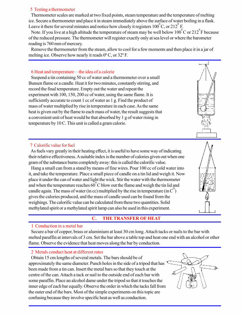
6 Heat and temperature—the idea of a calorie
Suspend a tin containing 50 cc of water and a thermometer over a small
Bunsen flame or a candle. Heat it for two minutes, constantly stirring, and
record the final temperature. Empty out the water and repeat the
experiment with 100, 150, 200 cc of water, using the same flame. It is
sufficiently accurate to count 1 cc of water as 1 g. Find the product of
mass of water multiplied by rise in temperature in each case. As the same
heat is given out by the flame to each mass of water, the result suggests that
a convenient unit of heat would be that absorbed by 1 g of water rising in
temperature by 10 C. This unit is called a gram calorie.
7 Calorific value for fuel
As fuels vary greatly in their heating effect, it is useful to have some way of indicating
their relative effectiveness. A suitable index is the number of calories given out when one
gram of the substance burns completely away: this is called the calorific value.
Hang a small can from a stand by means of fine wires. Pour 100 cc of cold water into
it, and take the temperature. Place a small piece of candle on a tin lid and weigh it. Now
place it under the can of water and light the wick. Stir the water with the thermometer
and when the temperature reaches 600
C blow out the flame and weigh the tin lid and
candle again. The mass of water (in cc) multiplied by the rise in temperature (in CO
)
gives the calories produced, and the mass of candle used can be found from the
weighings. The calorific value can be calculated from these two quantities. Solid
methylated spirit or a methylated spirit lamp can also be used in this experiment.
C. THE TRANSFER OF HEAT
1 Conduction in a metal bar
Secure a bar of copper, brass or aluminium at least 30 cm long. Attach tacks or nails to the bar with
melted paraffin at intervals of 3 cm. Set the bar above a table top and heat one end with an alcohol or other
flame. Observe the evidence that heat moves along the bar by conduction.
2 Metals conduct heat at different rates
Obtain 15 cm lengths of several metals. The bars should be of
approximately the same diameter. Punch holes in the side of a tripod that has
been made from a tin can. Insert the metal bars so that they touch at the
centre of the can. Attach a tack or nail to the outside end of each bar with
some paraffin. Place an alcohol dame under the tripod so that it touches the
inner edge of each bar equally. Observe the order in which the tacks fall from
the outer end of the bars. Most of the simple experiments on this topic are
confusing because they involve specific heat as well as conduction.

3 Measurement of the heat conducted through different substances
The steam can described in Chapter II, C 5, will serve as a hot plate
for experiments in conductivity if it is placed upside down on a tripod.
Steam is introduced through the long pipe and condensed in cold water.
Place a slab of cardboard on the hot plate and on it a small tin
containing 100 cc of water and a thermometer. Measure the rise in
temperature after 5 minutes and calculate the heat transmitted. Repeat
the experiment using slabs of equal thickness of metal, cloth, cork, etc.
4 Metals are good conductors of heat
Hold a piece of paper above a candle flame: it will char if brought near. Place a metal coin on the paper
and repeat the experiment: the metal will conduct away the heat and leave a pattern on the paper.
5 Conductivity of metal and wood
A piece of metal tube with a wooden rod fitted into it shows the same effect: if the wooden rod is held
over a flame, it will not burn. A penholder with a metal band at one end can be used for this experiment. The
same principle is involved in a simple experiment with a cigarette, a metal coin and a handkerchief. Wrap the
coin in the hand- kerchief, stretching the fabric tightly over it between finger and thumb. Press the red hot
ember of the cigarette on this part of the handkerchief; it does not burn.
6 Conduction with a metal game
Hold a piece of metal gauze in an alcohol or gas flame. Observe that the flame does not come through the
screen as the heat is conducted away from the flame by the wires. If you have gas in your room place a
burner under a tripod and cover it with a wire screen. Turn on the gas and light it above the screen. You will
observe that the gas burns only above the screen as the heat is conducted away by the screen and keeps the
gas below the screen from reaching its kindling temperature. This observation gave Sir Humphrey Davy his
idea for making the miners’ safety lamp which prevented the explosion of gases in the coal mines.
7 A model Davy lamp
The traditional experiments on the conductivity of
wire gauze can be followed by an improvised Davy
lamp. A Christmas candle enclosed in a cylinder of
wire gauze does not light a jet of gas played on it
from a rubber tube.
A block of wood or plasticine is used as a base.
8 Haybox thermos flask
Make a cloth bag to fit loosely round a bottle, and stuff it with kapok
and cotton waste. Enclose this in a cardboard or bamboo cylinder fitted
with carrying string. Although no vacuum is used, drinks are kept hot or
cold for several hours.

9 Water is a poor conductor of heat
Hold the bottom end of a test tube of cold water in the hand. Heat the top in a Bunsen flame until it boils.
The fact that you can still hold the bottom shows how bad a conductor water is.
10 Heat is transferred by convection in liquids
Secure a large glass jar that can be heated. The bottom part of a glass coffee-maker can be used. Fill the
jar with water. Put some grated blotting paper particles or sawdust in the water and give them time to
settle to the bottom. Now place the jar over an alcohol lamp and begin to heat it. Observe the paths taken
by the particles of paper. The paper particles follow the convection currents set up in the water.
11 What causes convection currents in water ?
Fill a large jar with cold water and weigh it accurately on a balance. Fill the jar with exactly the same
amount of hot water and weigh. You will observe that the jar of warm water weighs less. Volume for volume
cold water is heavier than warm water; so when water is heated convection currents are set up, the warm
water being lifted, because of buoyancy, by the cold surrounding water. In other words hot water is less
dense than cold, and this is the cause of convection currents in a liquid.
12 Effect of temperature on the density of water
The sensitive balance described on earlier can be used to demonstrate changes of up thrust when a body
is suspended in cold and then warm water. Replace one of the pans of the balance by a key or other
suitable metal object hung from the beam. Counterpoise this in a can of water. Now blow steam into the
water to raise its temperature and notice that the key apparently becomes heavier owing to reduced up
thrust on it. As metals expand much less than liquids the effect is easily seen. If absolute measurements are
required, a correction for the expansion of the metal may be made, or an inexpansible alloy such as Invar
should be used in place of the key.
13 At what temperature does water attain its maximum density?
Put a piece of ice into a glass of water. Arrange two thermometers so that one measures the temperature
near the surface, and the other the temperature near the bottom. It will be noticed that the water cooled by
the ice falls to the bottom; this continues until the water at the bottom of the glass reaches a temperature of
about 40 C. It will stay at this temperature for a long time, the colder water remaining higher up near the ice.
From this it can be deduced that the water at 40 C is denser than the water at 00 C. This curious behaviour
of water is of great practical significance in nature, and explains why a pond freezes from the surface
downwards while the bottom surface seldom falls below 40C.
14 Another way to show convection currents in water
Fit an ink bottle or paste jar with a cork carrying two pieces of glass
tubing as shown in the diagram. One piece of tubing should be drawn
out to a jet like the end of a medicine dropper. This tube should be put
just through the cork and should extend about two inches above. The
other tube should be just level with the cork and extend nearly to the
bottom of the bottle. Fill the bottle with very hot water that has been
coloured deeply with ink.
Now fill a large glass jar such as a battery jar or cookie jar with very cold water. Rinse off the ink bottle
and quickly place it on the bottom of the large jar. Observe what happens. Can you explain this?

15 How to make a model hot water heating system
Make a flask from a large electric bulb. Secure a wide-mouthed
bottle and a funnel. Fit the bottle with a cork carrying three glass tubes
arranged as shown in the diagram.
Fit the flask with a two-hole cork carrying two glass tubes, one
going just through the cork and the other extending nearly to the
bottom. Attach the funnel as shown. This serves as the expansion tank.
Fill the system with water and heat. Observe which part of the radiator
gets hot first. Can you explain how the water circulates by convection
currents?
16 Convection currents in air
Obtain a circular disk of thin tin as used to close tobacco containers. Cut
teeth in the circumference and pivot it on a bent knitting needle. Hold it
above a candle flame, and it will revolve rapidly. A paper spiral supported on
a knitting needle will revolve in a similar way.
Bring a piece of red-hot iron into contact with ‘solid methylated spirit’
(Meta fuel). The vapour immediately recrystallizes and tills the room with a
highly diverting snow- storm. The crystals are set in motion by draughts and
convection currents already in the room.
Another way of showing these air currents is by making use of the
difference in refractive index of warm and cold air. A 12 volt car bulb without
reflector will cast ‘shadows’ of convection currents from an electric heater or
even from an ordinary electric lamp bulb.
See also Chapter VIII, experiment B 6.
17 How convection currents cause winds
See Chapter VIII, experiment B 6.
18 Convection currents and ventilation
Use the box which you used for a study of winds in Chapter
VIII, experiment B 5, page 97. Bore four holes in each end, two
above and two below. Put solid corks in all the openings including
the two on the top where the lamp chimneys were placed for the
other experiment. The holes in the opposite ends represent
windows which may be opened or closed at the top and at thebottom. Put four candles in the box and light them. You are now ready to study the best conditions for
ventilation. Close all the windows and observe the candles for a little while. Now try different combinations
of openings. One window open at top and bottom. One open at the top, the other at the bottom. Both
open at the top. One only open at the bottom. Both open at the bottom. One only open at the top. What
window openings provide the best ventilation ?
19 Heat is transferred by radiation
In the previous experiments you have seen that heat can be transferred by material sub- stances, by solids,
liquids and gases. Heat can also be transferred by wave motion, even across a vacuum. This is called
radiation. Heat travels by radiation almost instantaneously. This experiment will demonstrate some interesting
things about radiation. Hold your hand under an unlighted electric bulb, palm upward. Turn on the electricity.
Can you feel the heat almost as soon as you turn on the bulb? The heat could not have reached your hand
by conduction because air is a very poor conductor of heat. Neither could it have reached your hand by
convection because this would have carried the heat upward away from your hand. It actually came to your
hand carried by very short waves. Radiation carries heat in every direction from the source.

20 Radiant heat waves can be focused
Hold a reading glass lens in the sun and focus the rays to a point on a wad of tissue paper. You will
observe that the tissue paper catches fire from the focused heat rays. Try the effect of using tissue paper
blackened with Indian ink or soot. Does it catch alight more readily ?
21 Radiant heat waves can be reflected
In the above experiment note the distance from the reading glass to the tissue paper. Place a tilted mirror
about half this distance from the lens. Feel about with your hand above the mirror until you find the point
where the heat waves are focused. Hold a bit of crumpled tissue paper at this point and see if it will catch
alight.
22 Different kinds of surfaces affect radiation
Secure three tin cans of the same size. Paint one white, inside and out, and another one black; leave the
third one shiny. Fill the three cans with warm water at the same temperature. Record the temperature. Place
cardboard covers on each can, set them on a tray, and then put them in a cool place. Record the
temperature of the water in each can at five- minute intervals. Was there a difference in the rate of cooling?
Which surface was the best radiator of heat? Which the poorest?
Next fill the cans with very cold water, record the temperature, cover each can and place them in a warm
place or in the sun. Record the temperature of the water at five- minute intervals. Which surface was the
best absorber of heat? Which the poorest?
23 Another way to show how surfaces affect radiation
Cut two vertical slits opposite each other on the side of a cylindrical tin, so that the
surface of the tin is divided into two parts. Blacken the inside of one half leaving the other
half shiny. Put a lighted candle inside the tin, in the exact centre of the base.
A difference in temperature of the two outside surfaces can be detected with the
fingers.
Matchsticks fastened to the outside with wax can also be used as indicators, and the
one behind the black surface will fall off first.
An alternative experiment is to use a coiled cylinder of fine wire gauze wrapped round
the top of the tube of a Bunsen burner as emitter and blackened thermometers as
detectors of radiation.
24 A simple thermoscope
Flasks, or cut-off light bulbs, can be used to construct this
apparatus. Besides the experiment illustrated with the candle, it
works well for other experiments, e.g., the Leslie Cube.
Fit both bulbs with corks and tubes about 15 cm in length.
Pass the lower ends of the tubes through flat corks and, having
made holes about 22 cm apart in a suitable base- board, glue
the tubes in a vertical position and connect the open ends by
rubber tubing. Remove one bulb and blacken the other in a
candle dame. Pour liquid into the U tube so formed until the level is about 7.5 cm above the baseboard.
Replace the clear bulb and slide the tube in or out a little so that the liquid remains level. Place a candle
equidistant between the bulbs and wait for results.
25 How heat losses can be reduced
Secure four large tin cans of the same size and four smaller tin cans of the same size. Put three of the small
cans inside three of the larger ones and pack insulating material under and around each of the smaller cans.
Pack one with shredded newspaper, the second with sawdust and the third with ground cork (other more
convenient insulating materials may be substituted). Inside the fourth large can place the small can resting on
two corks. Fit paste board covers to each can. Have a hole in each cover for a thermometer. Now fill each
small can to the same depth with water that is nearly boiling. Record the temperature of the water in each
can. Take the temperature of the water in each can at five-minute intervals and notice which is the best
insulator as indicated by the slowest rate of cooling.
D. MELTING AND BOILING
1 Observing a boiling liquid
Secure a very large Pyrex beaker or a large tin can. Fill the vessel nearly full of cold water and place it
over a flame. Leave it there until it boils. You will first observe air bubbles coming out of solution in the water
and rising to the surface. When the water is near the boiling point, steam bubbles will form and collapse
almost at once. As the boiling point is reached, the bubbles will form at the bottom and rise to the surface
before bursting.
2 How to boil water in paper
Secure some smooth paper: either wrapping paper or writing paper will do. Make a box about 25 cm
square by folding the corners up and pinning them. Fill the box about half full of water and place it on a
burner. You can boil the water without burning the paper. The paper conducts heat from the flame to the
water and does not catch fire because its kindling temperature is above the boiling point of water (1000C or
2120 F)
3 Boiling water by cooling it
Fit a flask with a tight solid stopper. Remove the stopper and fill the flask a little more than half full of
warm water. Bring the water to the boiling point over a flame. Put the stopper tightly in the flask and invert it
over a pan or sink. Pour cold water over the flask: the water starts boiling again. Put a piece of ice on the
flask. Cooling condenses the water vapour above the water and reduces the pressure on the water. When
the pressure is reduced, water boils at a lower temperature, This explains why it takes so long to cook
things at high altitudes.
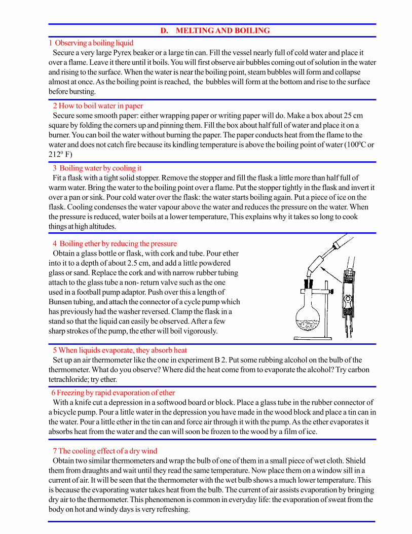
4 Boiling ether by reducing the pressure
Obtain a glass bottle or flask, with cork and tube. Pour ether
into it to a depth of about 2.5 cm, and add a little powdered
glass or sand. Replace the cork and with narrow rubber tubing
attach to the glass tube a non- return valve such as the one
used in a football pump adaptor. Push over this a length of
Bunsen tubing, and attach the connector of a cycle pump which
has previously had the washer reversed. Clamp the flask in a
stand so that the liquid can easily be observed. After a few
sharp strokes of the pump, the ether will boil vigorously.
5 When liquids evaporate, they absorb heat
Set up an air thermometer like the one in experiment B 2. Put some rubbing alcohol on the bulb of the
thermometer. What do you observe? Where did the heat come from to evaporate the alcohol? Try carbon
tetrachloride; try ether.
6 Freezing by rapid evaporation of ether
With a knife cut a depression in a softwood board or block. Place a glass tube in the rubber connector of
a bicycle pump. Pour a little water in the depression you have made in the wood block and place a tin can in
the water. Pour a little ether in the tin can and force air through it with the pump. As the ether evaporates it
absorbs heat from the water and the can will soon be frozen to the wood by a film of ice.
7 The cooling effect of a dry wind
Obtain two similar thermometers and wrap the bulb of one of them in a small piece of wet cloth. Shield
them from draughts and wait until they read the same temperature. Now place them on a window sill in a
current of air. It will be seen that the thermometer with the wet bulb shows a much lower temperature. This
is because the evaporating water takes heat from the bulb. The current of air assists evaporation by bringing
dry air to the thermometer. This phenomenon is common in everyday life: the evaporation of sweat from the
body on hot and windy days is very refreshing.
8 How heat changes solids to liquids
Place samples of such things as lead, solder, ice, sealing wax, paraffin wax in separate containers that may
be heated. Small tin cans or lids will be useful. Experiment with these and see if you can get some
information on the relative amount of heat needed to melt each sample.
9 Freezing water with ice and salt
Crack some ice into small lumps and place a layer in the bottom of a large can; cover this with kitchen salt
and then add other layers of ice and salt. Put some water in a smaller tin can, and place this tin inside the
large can. Then add more layers of ice and salt until the large can is full. Record the time taken to freeze the
water in the small tin. Compare this with the time required to freeze the same amount of water if only ice is
used in the large can.
10 Water expands when it freezes
Secure a small metal can which has a screw top. Fill it to overflowing with water and then screw the top
on so that there is no air space. Bury the can of water in a mixture of ice and salt and leave it for some time
until the water freezes. You should obtain some interesting results.
11 Heat is absorbed when solids melt
Secure a small container of chopped ice and find its temperature with a thermometer. Place the container
over a flame and observe the temperature until all the ice is melted. When did the temperature begin to rise?
Why did it not rise for some time? What became of this heat energy?
12 Melting by pressure and refreezing
When you apply pressure to ice you lower the freezing point. This is why skates move so easily over ice.
Hold an ice cube or a piece of broken ice in each hand. Press them together over a piece of paper. Can you
make water come from the ice with pressure? Push two ice cubes together forcibly and then release the
pressure. Try to separate the ice cubes. The water refreezes when you release the pressure, holding the ice
cubes solid.
13 Latent heat of steam found by using a tin
The rate of heat supply of a flame to 100 g of water in a tin may be found by taking the temperature at
intervals and plotting a time- temperature graph.
When the water begins to boil there is no further rise in temperature but the rate of heat supply is the
same. If one disregards the water lost by evaporation in bringing it to the boil, the heat required to boil 100
g of water completely away (that is until the bottom of the tin is dry), can be found from the time required
for this to happen.
14 Latent heat found by using a hollow solid
An alternative way of determining the latent heat of steam is to use a heavy hollow metal solid as a
condenser. A teapot can be used for a rough estimate.
The mass of water condensed in the teapot when steam from a kettle is passed into it depends on the heat
capacity of the teapot.
If a brass axle cap is used, it should be fitted with a bung having inlet and exit tubes. When steam is
passed into the apparatus, some time elapses before any comes out of the exit tube, because it is being
condensed by the cold metal. After steam has issued for a few minutes, and the metal is therefore at 1000
C,
the steam supply should be stopped. The mass of steam condensed is found by taking its volume with a
measuring cylinder. Given the specific heat, mass and initial temperature of the metal, the heat absorbed by it
in condensing the steam is calculated.

15 Latent heat of ice
A rough value of the latent heat of ice can be obtained by measuring how much ice is melted when a
heated solid is buried in ice shavings.
Weigh the solid of known specific heat and raise its temperature to 1000 C by suspending it in water from
a piece of cotton. Quickly transfer it to a funnel of powdered ice, and collect the resulting water in a test
tube or measuring cylinder.
Calculate the heat given up by the metal in cooling to 00 C.
This apparatus can also be used to demonstrate the difference in specific heat of different materials. The
volume of water obtained in each case provides a comparison of the specific heats.
16 Specific heat using a teapot
Pour boiling water into a weighed teapot at room temperature. The temperature will remain steady at
about 960C. Measure the mass of hot water used when it has cooled a Little, using a measuring cylinder.
Assuming there is no loss of heat to the surroundings, the specific heat of the material can be calculated.
This experiment forms an introduction to the subject of specific heat, or might be used as part of an
investigation of the qualities of different materials used in teapots.
17 Specific heat comparison
To compare the specific heats of different metals, prepare cylinders
of each of them of the same mass. Bring them to the temperature of
boiling water and transfer them to a nearly vertical inclined plane,
made from a piece of wood, and having a sheet of beeswax cell-
former fastened to the front, but held away from the board by corks.
The cylinders will slide down the incline, melting tracks through the
wax whose length will depend on the specific heat of the metal used.
18 Measurement of specific heat
Procure a piece of metal (say, 100 g of iron), and a tin containing
100 g of water. Suspend both above similar spirit lamps as in the
diagram (a small Bunsen flame will do).
The iron weight needs a hole to be drilled in it to fit the bulb of a
thermometer loosely; the tin of water also requires a thermometer in it
which can be used as a stirrer.
It is assumed that the lamps are supplying heat at the same rate.
They are applied to these bodies for the same length of time.
Both lamps should be removed when the thermometer in the iron
reaches 80 degrees, as it will probably then overshoot the mark to
100 degrees. The surprising difference in temperature emphasizes the
effect of specific heat. Since 1 g of water absorbs 1 calorie for a
temperature rise of l0
C, the heat supplied to both iron and water is
(100 x rise in temperature of the water). The heat supplied to the iron
is (100 x S x rise in temperature of iron). So the specific heat
S = rise in temperature of water
rise in temperature of iron
19 Specific heat-hollow solids
An experiment somewhat similar to the teapot determination can be carried out using a hollow solid such
as a brass axle cap or a short connector for iron tubing. Heat losses can be minimized by using a cloth to
cover these vessels. The procedure is the same as before. Boiling water is poured in. The final steady
temperature recorded will be much lower than that in the case of the teapots.
If a brass object weighs 1 kg the final temperature may be in the region of 600 C.
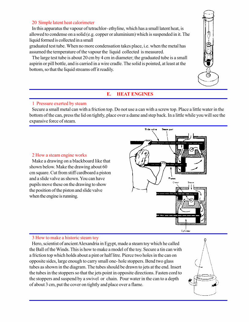
20 Simple latent heat calorimeter
In this apparatus the vapour of tetrachlor- ethyline, which has a small latent heat, is
allowed to condense on a solid (e.g. copper or aluminium) which is suspended in it. The
liquid formed is collected in a small
graduated test tube. When no more condensation takes place, i.e. when the metal has
assumed the temperature of the vapour the liquid collected is measured.
The large test tube is about 20 cm by 4 cm in diameter; the graduated tube is a small
aspirin or pill bottle, and is carried in a wire cradle. The solid is pointed, at least at the
bottom, so that the liquid streams off it readily.
E. HEAT ENGINES
1 Pressure exerted by steam
Secure a small metal can with a friction top. Do not use a can with a screw top. Place a little water in the
bottom of the can, press the lid on tightly, place over a dame and step back. In a little while you will see the
expansive force of steam.
2 How a steam engine works
Make a drawing on a blackboard like that
shown below. Make the drawing about 60
cm square. Cut from stiff cardboard a piston
and a slide valve as shown. You can have
pupils move these on the drawing to show
the position of the piston and slide valve
when the engine is running.
3 How to make a historic steam toy
Hero, scientist of ancient Alexandria in Egypt, made a steam toy which he called
the Ball of the Winds. This is how to make a model of the toy. Secure a tin can with
a friction top which holds about a pint or half litre. Pierce two holes in the can on
opposite sides, large enough to carry small one- hole stoppers. Bend two glass
tubes as shown in the diagram. The tubes should be drawn to jets at the end. Insert
the tubes in the stoppers so that the jets point in opposite directions. Fasten cord to
the stoppers and suspend by a swivel or chain. Pour water in the can to a depth
of about 3 cm, put the cover on tightly and place over a flame.

4 How to make a model steam turbine
A turbine model can be made from a tin fitted with a vane wheel. The vanes are
made by cutting radial slots from a circular piece of tin, and twisting the blades
which remain.
The axle is a piece of knitting needle, and the axle support is made from a strip
of tin bent into a U piece and soldered to the top of the can.
A hole for a steam jet should be made opposite the vanes.
5 How to make a model turbine from glass
Very little glass blowing experience is needed to make this
model. Seal one end of an ordinary piece of glass tubing in a
flame and blow a bulb about 1.5 cm in diameter.
Soften the bottom of the bulb and press a pencil into it. This
will make a depression to serve as a lower bearing for the
turbine. Bend the top of the tube over at 90 degrees and draw
it out to a jet bent at right angles again. Half fill the bulb with
water by heating it and then immersing the open end under the
surface of a beaker of water. Make a wire frame to act as a
support as shown in the drawing.
6 Heat engine from an old metal polish tin
The tin is supported horizontally on two copper pipes
which serve as exit tubes. They are soldered through the
centre of the bottom and the cap respectively. The tin is
partially filled with water and rests on two iron brackets
screwed to a wooden base.
7 To show the force of exploding gas
8 How petrol vapour is exploded in an engine
9 How to make a fire syringe
“BE A GOOD SCIENTIST. FOLLOW INSTRUCTIONS EXTREMELY CAREFULLY.
WEAR PROTECTIVE CLOTHING WHEN WORKING ON ANY EXPERIMENTS
THAT INVOLVE FIRE OR EXPLOSIONS.”

CHAPTER XIV
Experiments and materials for the study of magnetism
1 Natural magnets
Magnetic iron ore is quite common in many parts of the world. If it cannot be obtained locally, any supply
house will provide it for a small cost. Secure a piece of such iron ore. This is a natural magnet. Sprinkle
some iron filings or finely cut pieces of steel wool on a sheet of white paper and observe how the ore
attracts them. Try picking up heavier things made of iron, such as paper clips or carpet tacks. Bring the lump
of ore near a compass and observe. Do all parts of the lump affect the compass in the same way?
2 Securing artificial magnets
Strong and useful artificial magnets for the study of magnetism can be obtained from old radio loudspeak-
ers, from old telephone receivers and from old automobile speedometers. Magnets can frequently be
purchased in the market and may always be obtained from scientific supply houses. Artificial magnets are
made in many shapes such as horse shoe, U-shaped and straight or bar magnets.
3 How to magnetize a steel rod
Use a piece of magnetic iron ore or another magnet to magnetize a steel knitting needle. a darning needle,
an iron nail, a piece of clock spring or watch spring. This may be done simply by stroking the bar several
times with the magnetized substance. If you wish to make a bar magnet with opposite poles at either end,
use an artificial magnet. Begin at the centre of the unmagnetized bar and stroke toward the end using one
end of the magnet. After several strokings turn the rod around and stroke from the centre to the other end
using the opposite pole of the magnet. Test your results by using the rod to pick up iron filings or by ap-
proaching it to a compass.
4 How to make bar magnets
Secure some flat pieces of hard steel. Old hack or metal saw blades are useful. Lengths of steel from a
clock spring may be used. Cut the steel into 15 cm lengths. Next stroke the opposite ends of each piece
with alternate ends of a strong magnet as instructed in experiment 3 above. Test each bar magnet with a
compass. The two ends of the bar magnet should affect the compass in contrary ways. Hard steel is often
quite difficult to magnetize. One should place the piece of steel on a table and strike the pole of the magnet
against it as you stroke toward the end.
5 How to make a turntable cradle for magnet study
Select a piece of heavy wire. The wire from a coat-hanger will do
very nicely. Bend it into the shape shown in the diagram. The distance
between the two hooks at the ends should be small enough to cradle
the shortest bar magnet that will be used.
Suspend the cradle with fine copper wire or nylon fishing line from a
convenient hook or other support. Place a bar magnet in the cradle
and bring other magnets near it.
6 The concentration of magnetism in a magnet
Pour a considerable quantity of iron filings on a sheet of paper. Roll a bar magnet in the iron filings and
observe that most of the filings stick to points near the ends of the bar. These places on a magnet where the
magnetism seems to be concentrated are called magnetic poles. Repeat using magnets of other shapes such
as a horseshoe or a U shaped magnet.
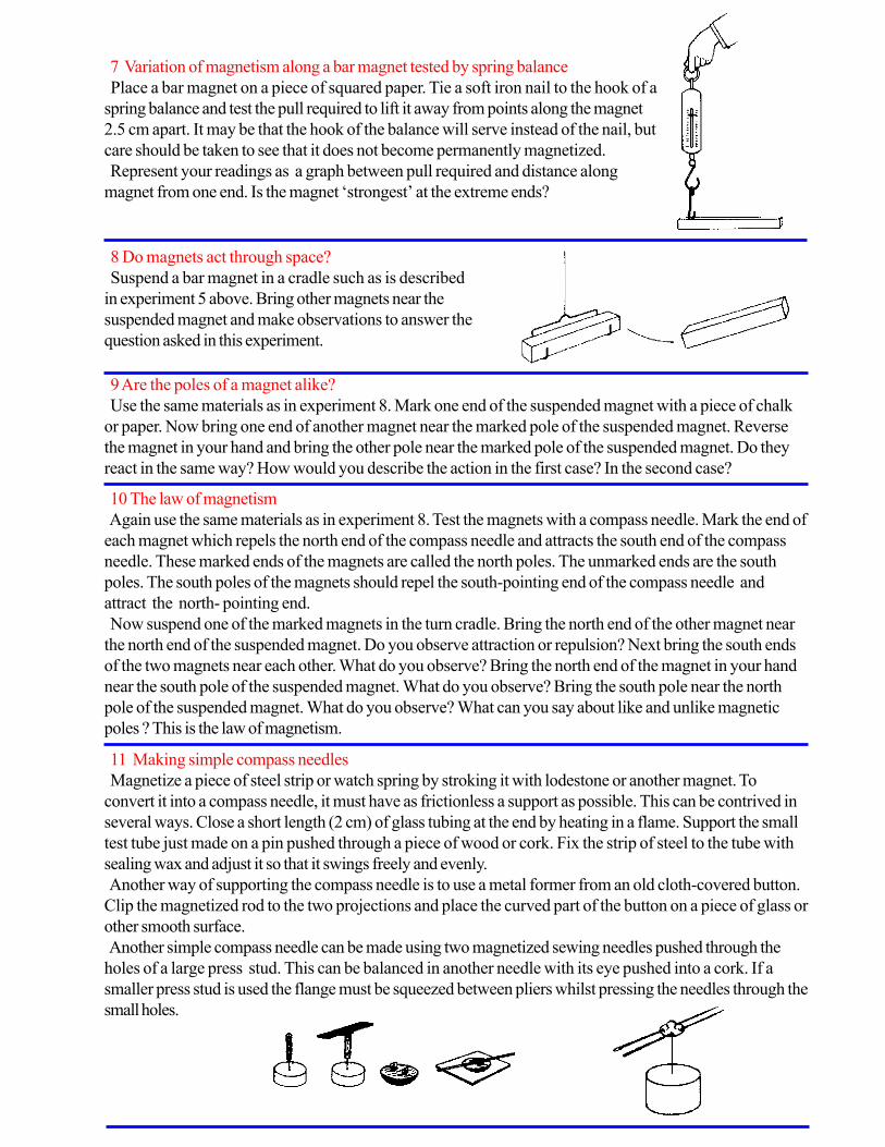
8 Do magnets act through space?
Suspend a bar magnet in a cradle such as is described
in experiment 5 above. Bring other magnets near the
suspended magnet and make observations to answer the
question asked in this experiment.
9 Are the poles of a magnet alike?
Use the same materials as in experiment 8. Mark one end of the suspended magnet with a piece of chalk
or paper. Now bring one end of another magnet near the marked pole of the suspended magnet. Reverse
the magnet in your hand and bring the other pole near the marked pole of the suspended magnet. Do they
react in the same way? How would you describe the action in the first case? In the second case?
10 The law of magnetism
Again use the same materials as in experiment 8. Test the magnets with a compass needle. Mark the end of
each magnet which repels the north end of the compass needle and attracts the south end of the compass
needle. These marked ends of the magnets are called the north poles. The unmarked ends are the south
poles. The south poles of the magnets should repel the south-pointing end of the compass needle and
attract the north- pointing end.
Now suspend one of the marked magnets in the turn cradle. Bring the north end of the other magnet near
the north end of the suspended magnet. Do you observe attraction or repulsion? Next bring the south ends
of the two magnets near each other. What do you observe? Bring the north end of the magnet in your hand
near the south pole of the suspended magnet. What do you observe? Bring the south pole near the north
pole of the suspended magnet. What do you observe? What can you say about like and unlike magnetic
poles ? This is the law of magnetism.
11 Making simple compass needles
Magnetize a piece of steel strip or watch spring by stroking it with lodestone or another magnet. To
convert it into a compass needle, it must have as frictionless a support as possible. This can be contrived in
several ways. Close a short length (2 cm) of glass tubing at the end by heating in a flame. Support the small
test tube just made on a pin pushed through a piece of wood or cork. Fix the strip of steel to the tube with
sealing wax and adjust it so that it swings freely and evenly.
Another way of supporting the compass needle is to use a metal former from an old cloth-covered button.
Clip the magnetized rod to the two projections and place the curved part of the button on a piece of glass or
other smooth surface.
Another simple compass needle can be made using two magnetized sewing needles pushed through the
holes of a large press stud. This can be balanced in another needle with its eye pushed into a cork. If a
smaller press stud is used the flange must be squeezed between pliers whilst pressing the needles through the
small holes.
7 Variation of magnetism along a bar magnet tested by spring balance
Place a bar magnet on a piece of squared paper. Tie a soft iron nail to the hook of a
spring balance and test the pull required to lift it away from points along the magnet
2.5 cm apart. It may be that the hook of the balance will serve instead of the nail, but
care should be taken to see that it does not become permanently magnetized.
Represent your readings as a graph between pull required and distance along
magnet from one end. Is the magnet ‘strongest’ at the extreme ends?

12 A razor blade compass box
Magnetize an old three-hole razor blade by stroking it with a bar
magnet. Push an old laundry stud or a piece of closed glass tube
through the central hole. Glue a disc of card to the blade and
suspend the combined compass on a pin stuck through a slice of
cork. Mark the position of north on the top of the card. Enclose
the compass in a cardboard box with a circular window in it
made of cellophane. Draw a reference line on the box.
13 To determine magnetic north
Float a piece of flat cork 10 cm by 3 cm in a saucer of water.
Magnetize a short length of hacksaw blade or other steel and fix
it to the cork so that its teeth are downwards and its length is
along the cork slab. When it comes to rest, sight along its upper
edge using two large pins. The line joining the feet of the pins is the
Magnetic Meridian.
14 A demonstration compass needle
Rivet together two old hacksaw blades through the holes at each
end and then magnetize them. Use a closed piece of glass tube as a
support. Push this between the blades at the midpoint and balance
it on a knitting needle driven vertically into a block of wood. Fix
the bearing in position with sealing wax or other adhesive. Push
wire indicators N and S between the blades at the extreme ends.
15 A model showing the earth’s
A ball or round fruit is needed to represent the earth in
this model. Support it on a wooden meat skewer inclined
at an angle. This represents the axis of rotation of the
earth.
Pierce the ‘earth’ with a magnetized knitting needle
which will be in the direction of the magnetic axis of the
earth.
Examine the external field using a small plotting compass
such as is often used as an ornament to a watch chain.
16 How to make a dip circle
Push a knitting needle through a cork in a direction parallel to a diameter of its
end. Balance it horizontally on a U piece of brass strip, using pins as an axle.
Take it off the knife edges and magnetize without disturbing the cork. When it is
replaced on the bearings, one end will be pulled downwards by the earth’s
magnetic field. The protractor serves to measure this angle of ‘dip’.
An alternative way of suspending the magnet is to use a piece of cycle valve
tubing with a pin pushed through it as a supporting axle. Knife edges can be
provided by two postcards held apart by corks maintained in position by draw-
ing pins. The position of dip can then be marked with a pencil and measured
later.
If metal ‘connectors’ are available, a more permanent device can be made by
soldering gramophone needles to it.
Magnetic Axis

17 A demonstration dip circle
Cut a ring of cardboard with an external diameter of 50 cm.
Fasten two laths across a diameter to serve as supports for the
dip needle. Cut a model dip needle from card and support it in
notches cut in the laths.
Such a model is useful when discussing the various errors of
the dip circle.
18 Exploring with a compass
Many things made of iron and steel are magnetized by the earth’s magnetism. It is interesting to explore
iron fence posts, iron bridges, etc., with a compass. Test them at both ends to see if they have magnetic
poles. Drive an iron rod into the ground and see if it becomes magnetized. Test it at the top and near the
earth. Test things around the school and at home with a compass.
19 What substances are magnetic?
Collect a variety of small objects made of paper, wax, brass, zinc, iron, steel, nickel, glass, cork, rubber,
aluminium, copper, gold, silver, wood, tin, etc. Place them in a box and test each object with a magnet to
see which ones are attracted and which are not.
20 Magnetizing a bar by hammering
Secure an iron rod about one metre in length. An iron curtain rod will do. Test it with a compass at each
end to see if it is magnetized. Hold the bar in a north-south direction and tilt. Strike the rod several sharp
blows in this position and then test it again with the compass. A bar can often be demagnetized by holding it
in an east-west direction and striking the end several times with a hammer.
21 Lines of force
A piece of plywood with two grooves cut in it to the depth of one ply is
useful for holding magnets and magnetic materials while testing the patterns of
their lines of force.
Permanent records can be made of such ‘filing maps’ if the paper used over
the magnets is first dipped in hot candle grease and allowed to cool. Place it
over the magnets under test, scatter filings on it from a height of 30 cm and tap
the paper. Fix the pattern formed by warming the waxed paper with the
medium flame of a Bunsen burner.
22 Mapping lines of magnetic force
An alternative to the familiar waxed paper method is to use a modern black line paper. This paper, em-
ployed by architects in place of the older blue-print paper, can be used in daylight.
Place the magnet in position on the paper and scatter on the filings to produce the required pattern.
Expose to the sun or bright daylight for 10 minutes, or to the light of a small are for 2 minutes, shake off the
filings and mop over with developer on a piece of cotton wool. The prints so made are positives, and the
paper can be varnished to form a permanent record.
23 What substances do magnetic lines of force go through?
Secure small pieces of as many of the following substances as possible: wood, glass, copper, brass, zinc,
pasteboard, plastic, iron, aluminium, etc. Place some iron filings on one side of the sheet and move a strong
magnet on the underside. By observing the iron filings you can tell which substances pass the magnetic lines
of force.
24 Magnetic induction
Place a bar of soft iron on a block of wood. Hold a tin-tack near it to test if
it is magnetized. While the tack is near one end of the bar, bring a strong
magnet near the other end. Is the bar magnetized? Remove the magnet and
test again. Is the bar still magnetized? Magnetism produced in a substance in
the vicinity of a magnet is called ‘induced’ magnetism. The effect involved is
called ‘magnetic induction’.

25 Testing for induced polarity
Test a strong magnet with a compass and mark the north pole and
the south pole. Place a compass on the table and hold the pointed
end of a 15 cm spike or piece of soft iron near it. Next bring the
north pole of the tested magnet near the top end of the spike without
letting them touch. Is a north or south pole induced in the end of the
spike near the compass? What would you guess the polarity of the
top end of the spike to be? Test it. Next hold the spike as before, but
bring the south pole of the tested magnet near the top end of the
spike. Is a north or south pole induced in the end near the compass?
In the top end of the spike?
26 What happens when magnet is broken ?
Magnetize a piece of clock spring or a hacksaw blade about 25 cm
long as instructed in experiment 3. Test the magnet with a compass to
be sure that it has a north pole at one end and a south pole at the
other. Mark the poles N and S with chalk. Does the compass show
any polarity at the centre of the magnet? Use a pair of pliers and
break the long magnet into two parts each about 12.5 cm long. Test
the polarity of each end of the two magnets. What do you observe ?
Mark the poles of each magnet N and S. Now break the two
magnets into four magnets. Test each end and mark it N or S.
Continue dividing the magnets, as many times as you can. Write a
conclusion to the question posed by this experiment.
27 Making a magnet with iron filings
Fill a test tube or glass toothbrush tube about two-thirds full of iron filings and stopper the end with a plug
of cotton or a cork. Stroke it with the poles of a strong magnet. Be careful not to shake the tube. Bring the
tube of filings near a compass, and you will observe that it behaves just like a solid magnet. Shake the tube
up well and again bring it near the compass. This time it does not influence the compass. From experiments
such as this scientists are led to believe that the magnetism in a magnet is associated with very small particles
of matter, perhaps molecules or atoms.
28 How to make floating magnets
Magnetize some used razor blades, being very careful not to cut yourself. Grease the blades lightly with oil,
Vaseline or kitchen grease. Fill a soup plate with water and float the razor blades on the surface. Now bring
a strong magnet under the floating magnets.
29 Some experiments with floating magnets
Magnetize seven or eight steel needles so that their points
all have the same polarity and the eyes all have the opposite
polarity. Push the needles through small hat corks about 13
mm in diameter so that about 1 cm of the needle is above
the cork. Fill a cereal dish or a soup plate with sloping sides
nearly full of water. Float the magnets, pointed end down,
in the water. Now bring one pole of a strong magnet above
the floating needles. Try the other end of the magnet. Such
floating magnets can often be arranged in different patterns
in the dish. Here are some to try.
30 A vibrator with a magnet
Set a U-shaped magnet on its side and place a needle or a razor blade on the lower pole. It will stand
upright. Strike the free end with a pencil and observe how well it vibrates.

31 Making a needle float in air
Use a threaded needle. Draw the needle over one pole of a magnet resting on the table. Let the needle
remain on this pole until it is thoroughly magnetized. Now carefully ease the needle from this pole and lift it
by the thread until it is over the other pole. Careful manipulation will make the needle float in the air above
the other pole. Can you explain why this happens?
32 How to make a card compass
Secure a wide-mouth glass jar. Fold a length of cardboard or stiff paper
so that it will go into the bottle and not be too long to turn inside. Magnetize
a steel darning needle (see experiment 3) that is just a little longer than the
cardboard. Push the magnetized needle through the cardboard and suspend
it on a thread so that the cardboard and needle balance. The needle may be
moved in or out to get the exact balance. Tie the end of the thread to a
match or longer piece of wood placed across the mouth of the jar.
33 A magnetic fishing game
Tie a strong magnet to a string several decimeters long. Attach the string to a short fishing rod or stick.
Spread a variety of small objects made of iron on a table behind a screen. Nails, tacks, screws, bolts, nuts,
thumb tacks, etc., may be used. To each of the objects assign points, 5 for a large nail, 4 for a screw, 3 for
a bolt, etc. The players take turns fishing over the screen with the magnet, and the score of each player is
determined by what he picks up with the magnet.
34 A magic magnetic spinner
Make a spinning top from a wooden spool which has been used for thread.
The spool is first cut in two. One piece is then shaped to a point like a cone.
Find a nail or other piece of iron rod that will fit tightly in the hole of the
spool. Cut off a length that will go through the cone and stick out about 1 cm
above the top. Grind the lower end, which just sticks out, to a very sharp and
evenly rounded point to make a spinning peg. Magnetize the spindle and
insert it in the wooden cone. Form a large S-curve from a piece of soft iron
wire. Place this on a smooth surface. If you set the top spinning near one of
the curves it will follow the wire to the end.
35 A magnetic boat
Fashion a small boat out of some soft wood. You may put a
mast and sail on it if you like. Hollow out the inside of the boat
or bore a small hole lengthwise in its hull. Magnetize an iron nail
and either put it in the hole or simply lay it inside the boat. Use a
plastic or aluminium pan for your ocean. You can fashion a shore
line from sand or wood. Control your boat by means of a
magnet which you move about under the container.
36 A sensitive magnetometer
Push a piece of copper wire through the cork of a test tube to serve as an
upper support for the suspension. Make a carrier for the magnet from thin
copper wire and solder a small vane to the lower end.
Attach a slip of mirror to the magnet carrier in order to reflect a beam of
light. Pour oil into the test tube to a depth of approximately 3 cm. Lower the
suspended magnet and carrier into the tube and adjust the upper support
until the damping vane just dips into the oil.

37 A vibration magnetometer
Small, strongly magnetized cobalt or ticonal magnets are now
available which, suspended from silk in a specimen tube, are
excellent vibration magnetometers. Since there is no ‘damping’
here, the time of vibration of the ‘swing’ is a measure of the strength
of the magnetic field in which it is placed.
A larger model is easily made by using a preserve jar with a
wooden top. A brass connector serves as a suitable clip for the
upper support. The magnet can then be lowered to touch the
bottom when the instrument is not in use. This precaution increases
the life of the suspension.
(N.B. To damp a vibration means to lessen its amplitude.)
38 Making a magnetizing coil
A piece of ordinary glass tubing wound with close turns of
copper wire serves to magnetize knitting needles. A torch battery
supplies the current required, but should not be left connected
longer than necessary.
39 To make a magnetizing coil for the electric supply mains
This is just a solenoid through which a heavy current is passed for a short time. The mechanical dimensions
are not critical, but the resistance of the wire must be chosen to suit the voltage employed. It will naturally be
lower when used with a 1Zvolt accumulator than with the 230-volt mains. For use with a 1Zvolt car battery,
4 layers of 22 SWG insulated copper wire are suitable, wound on a cardboard tube about 30 cm long and
diameter about 4 cm. If the coil is for use on the 230-volt mains, many more turns are needed. Fifteen
layers will give a strong magnetic field, though the number can be reduced if the last four turns are of
enamelled ‘Euraka’ resistance wire. As the current is only needed for a very short time, it is a good plan to
include in the circuit a ‘press down’ switch; a car starter switch is suitable.
Obtain a cardboard tube of the dimensions mentioned. Make two end supports with a hole into which the
tube can be glued. Wind on the wire, ·preferably using a lathe or hand drill. Secure the solenoid by screws
passed through a wooden base and into the end supports. Connect the ends of the wire to two insulated
terminals with the switch in series. Connect to the source of current, hold the object to be magnetized inside
the coil, and press the switch momentarily if direct current is used. The polarity produced will be the same
as that of the coil. With alternating current the polarity must be found afterwards, and the strength of magne-
tization will depend on the exact instant at which the current is switched off. It may therefore be necessary to
make more than one trial.
The coil can be used for demagnetizing with alternating current. The procedure is then to place the magnet
inside the coil, switch on the current and, whilst it is still flowing, withdraw the magnet along the axis to a
distance of about 2 yards outside the coil before switching off. It is quite safe to use such a coil for demag-
netizing a watch, though watchmakers use a much shorter coil.
“BE A GOOD SCIENTIST. FOLLOW INSTRUCTIONS EXTREMELY CAREFULLY.
WEAR PROTECTIVE CLOTHING WHEN WORKING ON ANY EXPERIMENTS
THAT INVOLVE FIRE OR EXPLOSIONS.”

Experiments and materials for the study of electricity
A. STATIC ELECTRICITY
All these experiments work best when the air is dry.
CHAPTER XV
CHAPTER XV
4 Dancing figures with static electricity
Secure an aluminium soup plate, about 2.5 cm deep, and a
glass plate to cover it. Cut some little doll figures from thin
tissue paper, as shown in the drawing. You may also cut out
some other figures like boxers. The figures should be just a little
shorter than the depth of the pan. Put the figures on the bottom
of the pan and cover with the glass. Rub the top surface of the
glass with a piece of fur or soft leather and watch the dance.
1 Electricity can be obtained by rubbing things together
Make a pile of finely divided cork particles by filing a cork. Cut up
some thin paper into small pieces. Obtain a plastic comb, a plastic
pencil, a plastic fountain pen, a piece of wax, a rubber balloon, a glass
or china dish and any other non-metallic objects you may find. Rub
each of these things briskly with your hair or a piece of fur and then
bring near the pile of cork particles. Rub again and bring near the pile of
thin paper. Observe what happens. Repeat the experiment rubbing each
article in turn with a silk cloth. Repeat using a piece of flannel.
TATIC ELECTRICITY
2 Static electricity is everywhere
Rub a blown up balloon on then bring it near some fine particles. Repeat using a comb
and a plastic ruler. Rub a fountain pen on your coat sleeve and test it for a static charge.
Hold two strips of newspaper, about 5 cm wide and 30 cm long, together. Stroke them
lengthwise with the thumb and finger of your free hand. What happens? Try to devise
other experiments showing that there is static electricity everywhere. your hair and
paper or cork
the study of electricity
3 Light from static electricity
Secure a fluorescent light bulb. Rub it
briskly with a piece of fur or flannel in a
darkened room. What do you observe?
Cut Figures from
Tissue Paper
Glass Plate
Aluminium
Soup Plate
Fur or Soft Leather

Experi
6 An electrostatic airplane
Cut a piece of light aluminium foil into the shape of a small air-
plane. Bring a charged ebonite or plastic rod near to it. It jumps to
the rod and receives the same kind of charge as the rod has, then it
jumps away again. It can then be kept in the air as long as is
desired, and its direction of flight can be guided by repulsion.
5 How to make the paper jump
Place pieces of paper underneath a sheet of glass resting on two
books. Rub the glass with silk or flannel. The papers begin to jump
about in an amusing way.
It is the charge induced on them by the charged glass which causes
them to be attracted. When they have given up their charge they fall
back again. The paper can be cut out in the shape of frogs.
7 Sparks from rubbing
Obtain four water glasses and stand them upside down on the
floor, close together. They should be near some metal object such
as a water pipe. Have someone stand on the glasses. Brush his
clothing for a full minute either with a piece of fur or a piece of
folded rubber like a cycle inner tube or a hot water bottle. Have
him stick his finger out toward the finger of someone standing on
the floor. Repeat and have him bring his finger near the water pipe.
Observe the results.
8 The balloon stays put
Blow up a toy balloon and rub it briskly with a piece of fur. Place it against the wall and observe that it
stays where you place it. Repeat, rubbing the balloon on your hair. Again repeat, rubbing the balloon on a
coat sleeve.
9 The newspaper stays on the wall
Spread out a sheet of newspaper and press it smoothly against
a wall. Stroke the newspaper with a pencil all over its surface
several times. Pull up one corner of the paper and then let it go.
Notice how it is attracted back to the wall. If the air is very dry,
you may be able to hear the crackle of the static charges.
10 There are two kinds of static charge
SparksRubber
PinsCork
Test Tube and Spike
Make a turntable by driving a long nail through a wood base. Push a
test tube into a hole made in a large flat cork. File the end of the nail to
a sharp point and invert the test tube over it. Set pins in the top surface
of the cork; they will brace the objects you place on the turntable.
Secure two test tubes or other glass rods, a piece of silk such as a silk
stocking, two plastic combs, and a piece of fur or flannel. Rub one
glass rod with silk and set it on the turntable. Rub the other glass rod
with silk and bring it near the one on the turntable. Repeat this experi-
ment until you are sure of the results.
Again rub the glass rod with silk and place it on the turntable. Now
rub a plastic comb with fur and bring it near the glass rod on the
turntable. Repeat until you are sure of the results.
Rub a comb with fur and set it on the turntable. Rub the other comb
with fur and bring it near the comb on the turntable. Repeat until you
are sure your observations are correct.

Again rub a comb with fur and place it on the turntable.
Rub a glass rod with sills and bring it near. Repeat until you
are sure of your observations.
When plastic is rubbed with fur the plastic takes a negative
charge of electricity and the fur takes a positive charge.
When glass is rubbed with silk the glass takes a positive
charge and the silk a negative charge. Your experiment has
indicated that like static charges repel while unlike charges
attract. This is a basic law of electricity. the air is dry Knife or
Metalic RodRubber or
Non conducting Pad
11 How to make a pith hall indicator for static charges
Secure some pith from the inside of a plant stem. Dry the pith thoroughly and then press it tightly into small
balls about 5 mm in diameter. Coat the pith balls with aluminium or gold paint. Attach each pith ball to a silk
thread about 15 cm in length. Make a wooden stand for the pith ball. Bring objects rubbed with silk, fur or
flannel near the pith ball and observe how it behaves. Notice that it is first attracted and then repelled. Such
a pith ball system is called an electroscope.
12 Metal foil ball electroscope
Roll up about 6 cms of metal foil from a cigarette packet into a bah of
about 6 mm diameter. Use an adhesive to attach it to a piece of silk or
nylon thread about 7.5 cm long. Secure the free end to a ball pen or other
insulator and rest the pen across the mouth of a jam jar so that the ball
hangs clear of the side. Bring any charged body near the ball; it should
first be attracted and then jump away. Now rub another plastic pen on a
celluloid set square or protractor. Hold the pen near the ball and let it take
a charge. Now bring the protractor near the charged ball. What does this
tell you about the two kinds of charge produced by rubbing ?
13 How to make an electroscope from newspaper
Cut a strip of newspaper 60 cm long and 10 cm wide. Crease it in
the centre and hang it over a ruler as shown in the diagram. Hold it
on the table and stroke several times with a piece of fur or flannel.
Lift it from the table with the ruler and observe how it acts. Rub a
comb or other plastic object with the fur or flannel and bring it
between the extended leaves of newspaper. Repeat until you are
sure of your results. Now rub a glass bottle with a piece of silk and
bring it near the extended leaves of the newspaper. Observe the
results and repeat until you are sure they are correct. What does this
experiment show?
Paper
Strip
Crease
Here
Ruler
Fur

14 How to make a metal leaf electroscope
To make a device for detecting charges of electricity, a jam jar, some wire, and pieces of
light foil or paper are needed.
A waxed cork is necessary to prevent the charge from leaking away. Push an L-shaped
piece of brass or copper through it, and hang a piece of tissue paper or a strip of aluminium
foil from the lower end.
If a charged body is brought near the rod, the leaves of the paper fly apart because they
have received the same kind of charge.
Insulating wax (see Chapter XVIII, item 21) or Perspex are better insulators and therefore
more satisfactory than the waxed cork.
15 How to make a shadow electroscope
A very useful piece of apparatus can be made with a chalk or cigar
box. The lid and bottom should be removed and replaced by a piece
of clear glass in one side and a piece of linen or paper in the other
(front in the diagram). The glass can be kept in position by tin corner
plates, and the paper can be glued on. A hole drilled in what is now the
top of the apparatus should fit a candle, ebonite or amber insulator with
a brass rod down its axis. The top of the brass rod carries a metal disk
forming the ‘cap’ of the electroscope and the other end has a strip of
tin soldered to it. The gold or aluminium leaf is attached to the upper
part of this tin, but the leaf is shorter. A thin glass thread, easily made in
a flame, is stuck to the leaf with glue. It has a small arrow at its lower
end. An electric bulb shines a light through the glass side of the appara-
tus and casts a shadow of the leaf and pointer on the screen. The
advantage of this arrangement over the usual projection electroscope is
that there is no inversion of the leaf, and movement and position of the
leaf can be seen by a large class. It is also possible to put a scale on
the paper calibrated in volts.
16 Fun with a kissing balloon
Blow up a toy balloon and tie a string to it about one metre long. You can draw faces on it with ink. Use a
soft stick dipped in ink. Now hold the string while someone strokes the face on the balloon with a piece of
fur or flannel. Let the balloon go and watch it touch everything around.
17 More fun with a balloon
Fix two balloons as in the experiment above. Rub the faces with fur. Hold the strings together and observe
how they repel. Put your hand between them and observe what happens. Bring one of the balloons near
your face. Repeat, using three balloons.
18 A static horse race
Cut small horses from a piece of folded
paper so that they will stand on a table.
Rub a hard plastic comb or fountain pen
with fur and notice that you can pull the
paper horses along the table. With several
horses, you can have a horse race.
EggPaper
Clips
Fountain Pen
Pencil put out
of balance
by the pen

19 How to get many sparks from static electricity
Obtain a piece of aluminium about 24 cm square. An alu-
minium cake tin will do. Heat the metal evenly over a flame.
Touch a stick of sealing wax or a wax candle to the centre of
the aluminium until it melts and sticks solidly to it as a handle. If
you want a more permanent handle you can punch a hole
through the aluminium and screw a plastic or wood handle to it.
Unfold an old rubber inner tube from an automobile tyre and
place it on a table. Stroke the surface of the rubber briskly with
a piece of fur or flannel for half a minute. Now place the
aluminium on the rubber and press it down hard with your
fingers. Remove your fingers and lift the metal by the handle.
Bring your finger near the metal and you should get a spark.
You can take many charges from the rubber without further
rubbing. Just press the metal against the rubber, press with your
fingers and lift by the handle.
Fur
Spark Here
Rubber Sheet
B. SIMPLE ELECTRIC CELLS AND CIRCUITS
1 To show how water flows in a tube
To make water flow from one can to another the source must be at
a higher level. Water flows downhill. You can demonstrate this by
using two large tin cans. Punch a hole near the bottom of each and
then enlarge the hole so it will take a one-hole cork or stopper. Put a
length of rubber tube on one can. Pinch the tube near the end with a
spring clothes peg. Place the can on the table and fill it with water.
Attach the tube to the other can. Let it also stand on the table.
Remove the clothes peg and watch the water flow. When does it
stop flowing?
2 To show bow electricity flows in a conductor
Use two tin cans as in the experiment above. Fasten the bare
end of a wire to one can. Place both cans on plates that have
been turned over. Fasten a spring clothes peg near the free end of
the wire. Now use the device for getting many sparks which you
made in experiment 19 of the previous section. Hook the free end
of the wire to the can to which the other end is already attached.
Place a charge on the rubber pad and bring the metal plate into
contact with the can to which the wire is attached. Repeat this
twenty times until you have a good charge on the can.
3 Another way to show how electricity flows
Use the can with the wire attached from experiment 2 above. This time attach the other end of the wire to
the leaf electroscope which you made in experiment 14 of the previous section. Place a charge on the can
with your spark device or from a plastic comb rubbed with fur. Observe the leaf of the electroscope.
Leaves will separate
as electricity flows
in from can
Clear Glass
Place the pith ball electroscope which you made in experiment 11 of the previous section so that it is in
contact with the other can. Next unhook the wire from the can, using the clothes peg as a handle and hook it
over the other can. Observe the pith ball. If your experiment is successful the electricity will flow from one
can to the other, and this will be shown by the pith ball.

4 How to make simple instruments to show electric currents
5 Electrical energy from chemical energy
Take two coins made of different metals. Clean them well with steel wool or fine sand paper. Fold some
paper towelling or blotting paper into a pad so that it is slightly larger than the coins. Soak the blotting paper
in salt water. Place one coin on top of the pad and the other underneath. Hold them between your thumb
and finger. Connect both ends of the coil from your sensitive meter to the coins and watch the compass.
6 Electricity from a lemon
Connect one wire from your sensitive meter to a piece of zinc cut from the
can of a used dry cell battery. Connect the other wire to a piece of copper.
Roll a lemon on the table, pushing on it with your hand to break up some of the
tissue inside. Push the two metal strips through the skin of the lemon, making
sure they do not touch. Observe the compass needle. Try this experiment using
a potato. Does the distance between the plates affect the meter reading?
7 How to make a simple electric cell
If dry batteries are not available, a simple voltaic cell can be used for many
experiments. Copper and zinc plates dipped into dilute sulphuric acid con-
tained in a jar work well, but the plates must be shaken occasionally to remove
the gases. A few crystals of potassium dichromate will remove the gases
chemically.
Procure some cotton-covered bell wire and neatly wrap from
50 to 60 turns to form a coil around a jar that is about 8 cm in
diameter. Slip the coil from the jar and fasten it securely with
short pieces of wire or with tape. Mount the coil on a wood
base. A little platform to hold the compass can be made by
cutting a hole in the cork for the coil to go through and then
fastening the cork and coil to the base with melted sealing wax.
Place a compass on the cork so that it points parallel with the
direction of the coil. Connect a dry cell to the coil and observe
the compass needle.
Binder
A more sensitive instrument can be made by building a little frame
from cigar box wood just large enough to hold the compass. Place
the compass in the frame and then wind about 20 turns of bell wire
over the frame as shown in the diagram.
The press-stud compass needle described in Chapter XIV,
experiment 11, can be used in both the above galvanoscopes. A
useful model can also be devised using this compass needle in a
matchbox. Remove the drawer from the box, and split open the
case as shown in the diagram. Wind 20 turns of 26 S.WG. double
cotton-covered wire tightly round the drawer. Support the com-
pass needle on a pin pushed through the bottom of the box.
Sand
in bottomTurns of
Bell Wire
Fix the split-open case to a plywood base with drawing pins.
Wind the bared end of the coil round the drawing pins, making
electrical contact so that they may be used as terminals.
CopperZinc
Lemon Juice
Acid

8 Other simple electric cells
You can make a simple Daniell cell for class use with a boot polish
or shallow meat jar.
First put in a layer of copper sulphate crystals about 1.5 cm deep,
moistened by about 0.5 cm of copper sulphate solution. Bury in this a
pancake spiral of copper wire with an insulated lead. Pour in a layer
of moist plaster of Paris and allow it to set.
For a negative plate use a strip of zinc sheet with a wire attached to
it and fill up the jar with dilute sulphuric acid. This small quantity of
acid can be thrown away when the cell is not in use.
9 How to make a simple accumulator or storage battery
Strip the lead covering from some electric cable. Cut it into pieces, 1.5
cm by 3 cm with a short projection or ‘lug’ on the short side of each.
Now prepare pieces of thin wood 1.5 cm by 3 cm from a matchbox to
act as ‘spacers’ to separate the plates. a. Simple electric cells and
circuits
Arrange a pile of plates with lugs placed alternately and separate each
plate by a spacer.
ZincCu
A larger cell for supplying current can be improvised from a jam jar and a piece of cardboard tube.
Mix copper sulphate with plaster of Paris to a thin cream and allow to set after pouring it into the space
between the jar and the central cardboard tube.
Mix another paste using plaster of Paris and zinc sulphate with a little sulphuric acid added. When the first
plaster has set, pour this mixture into the central tube. Insert a copper plate and a zinc rod as electrodes
before the pastes are hard.
10 How a dry cell is constructed
Remove the outer covering from an old dry cell. With a saw, cut the
battery in half and observe its structure. Observe the carbon or positive
pole in the centre, the zinc can which is the negative pole and the
material between the two poles which is the chemical that acts on the
plate of the cell. Notice how the zinc has been eaten away by the
chemical. Observe that the chemical materials were sealed into the zinc
can with hot pitch.Electrolyte mixed
with absorbent
material
Carbon Rod
Absorbing Paper
Zinc Casing
11 Using a dry cell in a circuit
Wrap the end of one of the short pieces of bell wire around the screw like
base of a flash- light bulb so that it holds the bulb tightly. Bend the remain-
der of the wire in the shape of the letter C. Set the tip of the flashlight bulb
on the centre terminal of a flashlight cell and adjust the free end so that the
springiness of the wire holds it against the bottom of the cell. If the
Connect the lugs on each side by a copper wire.
Immerse this arrangement in dilute sulphuric acid and pass a current to ‘form’ the plates. Even after a few
minutes the accumulator will light a small torch bulb. Alternate charging and discharging will improve the
condition of the plates.
connexions are tight, the bulb should light. Any flashlight bulb should operate when connected in this way,
but the kind made for a single cell flashlight will give a much brighter light.
Look closely at the bulb and notice the fine metal wire held in position by two heavier wires inside. A hand
lens will make this easier to see. The fine metal wire is made of wolfram, formerly called tungsten. Passage
of the electric current through the wolfram wire causes it to become very hot and give off light.
Turn the cell upside down and reverse the terminals. Note that the lamp still operates, though the electricity
is flowing in the opposite direction.
Make a diagram showing the path of the current through the bulb and around to the other end of the cell.
Develop the meaning of the term ‘electric circuit’

12 Flashlight bulb holders
Wire nails, screw eyes or staples can be used for supporting
flashlight bulbs. Three nails driven into the top of a cork as
shown in the diagram will support the bulb. Two more nails or
screws in the side of the cork and touching two of the vertical
nails serve to make electrical connexions.
13 How a flashlight works
Bend the bell wire and fasten it to the cell with a piece of
friction tape or rubber band. Adjust the wire so that the tip of the
bulb touches the centre terminal of the cell. Use the free end of
the wire as a switch by pressing it against the bottom of the cell.
14 How to connect cells in series
Connect three dry cells in series as shown in the diagram. Note that
the outside terminal of each cell is connected to the centre terminal of
the next cell or vice versa. When the cells are connected in this way,
the total voltage or electrical pressure is the sum of the voltages of the
cells. In this case, the total voltage is 4.5 volts since the voltage of
each cell is 1.5 volts.
Now connect the two lead wires to a lamp for a three-cell flashlight.
Disconnect one of the wires and attach the same lamp to a single cell.
Note the difference in brightness.
Connect the same lamp to two cells in series and compare the
brightness with that produced by one cell and by three cells. Cells
connected in series
15 How to connect cells in parallel
Connect three cells in parallel by attaching all the centre terminals to
one wire and all the outside terminals to another wire. Connect the
lead wires to a receptacle and insert a bulb for a one-cell flashlight.
Disconnect one of the cells and note that there is no difference in
the brightness of the lamp. Disconnect two cells and still the bright-
ness does not change. When cells are connected in parallel the total
voltage is no greater than that of a single cell.
Develop the distinction between the term ‘cell’ and ‘battery’. A
battery is two or more cells in connexion.
Rubber
Bands
Press
Here
Cells Connected in Series
Cells Connected in Parallel
16 Torch battery holders
When several torch cells are needed for an experiment they can be
held in spring clips fastened to a wooden base. These can be made of
steel baling strip bent in the form of an angle bracket and secured by a
terminal so that series and parallel arrangements are possible. For
greater security, circular clips of standard pattern can be added to grip
the cells round the circumference.
17 How lamps are connected in series
Connect three lamps in series and attach them to a single cell. Connect
the same three lamps to two cells in series, then three cells in series.
Unscrew one of the bulbs and note that the other two lamps go out,
because the circuit is broken. Relate this to Christmas tree lights. In many Lamps Connected in Series
Christmas tree cords, the lamps are connected in series. If one lamp in the series burns out, all the other
lamps go out because the circuit is broken.

18 How lamps are connected in parallel
Connect three lamps in parallel and attach them to a single cell.
Unscrew one of the bulbs and note that the other two stay lighted.
Increase the brightness of the lamps by adding a second cell in
series. Unscrew one bulb, then two bulbs, then three bulbs.
19 How a switch is used to control an electric circuit
Place a knife switch in a circuit with a cell and a lamp and turn the
light on and off by operating the switch. Replace the lamp with a
bell or buzzer and operate the switch. Replace the knife switch with
a pushbutton switch. Discuss the appropriateness of each kind of
switch for different uses.
20 How to make a simple switch
A simple switch can be made by fastening the end of a piece of bell
wire to a pencil with two rubber bands as shown in the diagram. A
second wire spliced under it makes a suit- able connection.
21 Another simple switch
Run a piece of bell wire through a spool (reel) and fasten it.
Wind a second piece around the spool (see the second figure).
22 How a door bell can be rung from two pushbuttons
Using two cells, two pushbuttons and a bell, show how a
doorbell can be operated from two different points, such as
the front door and back door of a house. Lay out the circuit
on a table as shown in the diagram. Draw an electrical
diagram of the circuit, using standard symbols.
23 How a light is controlled from two switches
With two double throw knife switches, two cells and a lamp, show
how a hall light can be operated from either the upstairs or the
downstairs switch. Lay out the circuit on a table as shown in the
diagram. Draw an electrical diagram of the circuit, using standard
symbols.
Adjust the free ends of the wires so that the switch can be opened
and closed easily.
Lamps Connected in Parallel
Front Door
Push Button
Back Door
Push Button

24 A miniature street lighting system
Cut two lengths of insulated bell wire about three metres long.
Remove the insulation at six places along each wire and connect
miniature light bulb sockets in parallel’ along them. Fasten the
wires between two chairs as shown in the diagram, leaving the
wires apart at one end. Connect the wires at the other end with
two dry cells. Screw torch light bulbs into the sockets.
25 How we get heat and light from electricity
Push the ends of two pieces of bell wire through a flat cork that
fits a small bottle. A suitable flat cork can be made by cutting off
the end of a longer cork, or a two-hole rubber stopper may be
used instead. Now untwist a piece of ordinary iron picture cord
and cut off a short piece of a single strand. Wind the ends of this
short piece of picture wire around the projecting ends of the
copper wires and insert the cork into a bottle. The result will serve
as a crude model of an electric lamp.
26 How fuses protect electric circuits
Examine normal and burned out fuses. Fuses are safety
devices that break an electric circuit when the circuit is
overloaded. The fuse wire melts when an unsafe amount of
current is flowing through a circuit.
Torch Light Bulbs
Dry Cells Sockets
Single Strand of
Picture Wire
Connect the electric lamp model into a circuit with one or more dry cells and a switch. Close the switch
until the fine wire (filament) begins to glow, then open the switch again. With care the lamp can be lighted
several times before the filament is consumed, but finally the heated iron wire combines with the oxygen of
the air inside the bottle and bums away. Commercially made lamp bulbs contain no oxygen, and the wolf-
ram wire is heated to such a high temperature that it glows brightly. In addition to protecting the filament, the
glass bulb also makes an electric lamp safe to use.
Cork
Strip of
Lead Foil
Cut a very thin strip of metal foil from a candy bar or other wrapper and fasten it between the ends of two
wires projecting through a cork. This will represent a model of a fuse that should work with dry cells.
Experiment with different types and widths of foil until the working model operates satisfactorily.
27 How a short circuit burns out a fuse
Place the model fuse shown in a circuit with several cells and a
lamp. Then short circuit the lamp. If the fuse does not melt, cut a
thinner strip of foil. Experiment with different kinds and widths of
foil until the fuse carries the current when connected properly but
melts when there is a ‘short’ in the circuit.
28 How to make a simple fuse holder Tin foil used for
cigarette and packing purposes is useful for experiments on
fuses. It can be cut in strips and stuck on a piece of gummed
Bare Wires
tape which will hold it flat. The metal foil with paper backing which was used during the war for radar
camouflage is excellent for the above experiment and can be cut easily with a pair of scissors to give differ-
ent fusing values. The ends can be held by bulldog paper clips to a slat of wood or a ruler. The device can
then be incorporated with the circuit board set if desired. Different lengths and widths of tin foil should be
tried to find the fusing current.

29 How electrical resistance varies with temperature
Connect a coil of about two metres of florist’s thin iron wire in series with a torch battery and bulb. Heat
the coil with a match; the increase in resistance will reduce the current so that the bulb no longer glows.
C. MAGNETISM AND ELECTRICAL ENERGY
1 An apparatus for building up simple electrical instruments
The different pieces of apparatus used in elementary electric-
ity have so much in common, electromagnets, switches, etc.,
that it is worth while constructing some multiple sets of appara-
tus in which they can be used in several different ways. The
following arrangements have been found useful for boys of 11-
13, and require little more than a penknife to assemble, once the
basic parts are made. The devices suggested are not entirely
foolproof, because little is learned of the difficulties of a subject
if one needs only to follow instructions to the letter.
The apparatus consists of a short wooden channel which acts
as a base for all experiments; a square-ended former for
winding a coil which fits the groove fairly tightly, a few terminals,
bits of tin, etc., are all that are required to make a Morse
sounder, buzzer, bell indicator, electromagnet repulsion meter
and attraction meter.
The coil is made of two square end pieces of wood with holes
in their centre. They are joined by cardboard tube glued into
these holes.
An old carriage bolt with the head cut off makes a convenient
iron core.
2 Magnetism from an electric current
Cut two lengths of copper wire and remove the insulation
from the ends. Connect the wires to a dry cell and arrange
the bare ends as shown in the figure. Place some iron filings
on a piece of paper and run one of the bare ends through
them. Now let the current flow through the circuit and
quickly lift the wire and observe the iron filings. Break the
contact and the iron filings will drop from the wire. Do not
leave the cell connected long; it will quickly run down when
connected this way.
The Channel
The Coil
The end Pieces
The Switch
Contact Discontact
Iron Filings Magnetic Effect
from Current
Without
Current
3 Another way to show the magnetic effect of a current
Repeat the experiment above, replacing the iron filings with a magnetic compass. Observe the difference in
the compass when it is placed over the wire and under the wire.

4 How to make an electromagnet from a bolt
Secure an iron bolt about 5 cm long which has a nut and
two washers. Place a washer at each end and screw the nut
just on to the bolt. Wind layers of insulated bell wire on the
bolt between the washers, making certain to leave 30 cm of
wire sticking out when you start winding the coil. When you
have filled the bolt between the washers with several layers
of turns of wire, cut the wire, again leaving 1 about 30 cm
sticking out. Twist the two ends of the wire close to the
ends, then wind short lengths of tape at the ends of the bolt
to keep the wire from unwinding. Remove the insulation
from the two ends of wire. Connect two dry cells in series
and attach your electro- magnet to them. Pick up some
tacks and nails. Disconnect one wire from the battery while
the tacks are still attached. Pick up other objects made of
iron or steel. Test the poles of each end of the magnet with a
compass while the current is turned on.
Taped
Insulation
Removed
5 How to make a horseshoe electromagnet
Secure a slender bolt or a piece of iron rod about 5 mm in
diameter and 30 cm long. Bend this into the shape of the letter
U. Wind a coil of several layers of bell wire on each arm of the
magnet, leaving the curving part free as shown. Begin at the end
of one arm. Leave about 30 cm of wire sticking out for connec-
6 How to increase the strength of an electromagnet
Wrap 100 turns of bell wire on a straight iron bolt. Connect the ends of the magnet with one dry cell and
count the number of tacks you can pick up with the magnet. Make three trials, and take the average as the
number that this magnet with one battery will pick up. Next attach two batteries to the magnet and repeat.
Count the number of tacks. How is the strength of the magnet affected by increasing the current flowing
through it?
Next wrap another 100 turns of wire on the magnet in the same direction. Attach to one battery and see
how many tacks you can pick up. Repeat three times and take the average. Compare this number with the
number picked up with one battery and a magnet of 100 turns of wire. How does increasing the number of
turns of wire affect the strength? Make a statement on increasing the strength of an electromagnet.
7 How to study the magnetic field of a coil
Use the apparatus made in experiment 1 of this section.
A postcard with a square hole cut in it enables the coil to
pass through. The card acts as a tray on which the effect of
using different cores in the coil can be studied by making
iron filing maps.
tions. Wind about three layers on this pole, then carry the wire across the top to the other end; be sure to
wind this pole exactly as shown in the diagram. Wind about three layers of wire on this pole. When you
have finished, tape the wire to keep it from un- winding. Remove the insulation from the ends of the coil,
attach to two dry cells, and test the poles of the electromagnet. One should be a north pole and the other a
south. If each has the same polarity, you have wound the second coil in the wrong direction. It will be
necessary to unwind the coil and rewind it in the opposite direction.
Try picking up different things with the magnet. Compare the strength of this electro-magnet with the
straight one you made.

8 How to make a repulsion meter
Use the equipment made in experiment 1 of this section.
A piece of tin can about 4 by 5 cm with a wire soldered to one
end is required for the ‘movement’ of the meter. A blob of solder on
the end of the wire acts as a gravity control to the meter.
The coil becomes magnetized when a current is passed. Both the
fixed and moving elements are magnetized in the same direction,
and repulsion occurs. The fixed element is a soft iron wire held in
position by a rubber band. It will give readings 0-5 amps, depend-
ing on the wire and the magnetic properties of the metals used.
9 How to make an attraction meter
Use the equipment made in experiment 1 of this section.
For this apparatus the channel is laid on its side with the coil fitted as
before. The iron core is pushed in and a current is passed. This attracts a
pear-shaped piece of tin can pivoted on a pin stuck in the end of the
block. A fine wire soldered to the tip of the metal acts as a pointer and
graduations can be made on a piece of card held in position by drawing
pins.
These are only a few of the devices which can be assembled from the
above components. A boy of 12 can discover many more: the electric
signal, the sucking bar, the relay, etc.
10 How to make a telegraph key and sounder
Again use the equipment made in experiment 1 of this section.
The coil should first be wound with any available copper wire,
the ends being fastened under the terminals.
The completed coil is pressed into the groove and the iron core
slid in; if necessary, wedge it in place with a piece of paper.
A strip of tin can about 10 cm long is then pressed into the saw
cuts in the edge of the channel and secured by a terminal. One of
the end pieces with a terminal in its lower hole will act as the
sounder.
11 How to make an electric buzzer
Use the equipment made in experiment 1 of this section.
A simple rearrangement of the circuit converts the sounder into a
buzzer. The contacts soon become fouled, and it is necessary to
scrape them with a penknife.
When the switch is depressed, the coil becomes a magnet, and the piece of tin can is pulled forward to hit
the metal core with a ‘click’: as it springs back at the release of the switch, it hits the terminal on the end
piece with a ‘clack’.

12 How to make a cigar box telegraph and a key
Seventy-five to 100 turns of magnet wire neatly wound on to a
6.5 to 8 cm bolt will serve for the coil. Leave enough of the
threaded end for two nuts and the thickness of the box, so that the
coil can be fastened to the box. For the armature, a 10 cm bolt, 5
mm in diameter and with a round head, is most satisfactory.
Support it between two nuts by a screw-eye fixed to the back of
the box so that the head will extend just beneath the coil. A block
of wood with a small piece of window glass cemented to it makes
an effective anvil. Attach the anvil securely to the box. Hot sealing
wax is ideal for both purposes. Any glue, however, will do. The
height of the anvil should be such as to allow not less than 3 mm of
clearance space for the end of the armature, and it should not
exceed this amount by more than a trifle. The remaining feature
now is a spring to pull the armature away from the magnet in case
it tends to cling after the current is broken. A rubber band will
work well. Slip it over the end of the armature and attach it to the
box with a thumb tack. Give it just enough tension to prevent the
armature from sticking to the magnet.
You are now ready to assemble a key. Secure a small piece of board about 8 cm by 15.5 cm and about
0.5 cm thick. Cut a strip of metal from a can about 2.5 by 13 cm. Go over it thoroughly with sandpaper or
steel wool to remove any lacquer or tarnish from its surface. A piece of clock spring is also excellent for this
purpose. Holes may be punched with a large nail and a sharp blow from a hammer. Set a screw in one end
of the block and attach the metal at the other end so that it will bridge the space when the metal is pressed
to the screw head.
Connect your telegraph sounder, two cells and key in series as shown. You are now ready for your trial
message. If, on vibrating the key, you do not get a series of clicks, it means that either your connections are
loose or an adjustment of the rubber band is needed.
Glass
Rubber Band
Magnet CoilArmature
Contact
ScrewClock
Spring
WasherSmall Brass
Bolt
13 Another way to make a buzzer
A buzzer is essentially the same as a telegraph instrument except
that it produces a buzzing sound instead of a clicking sound when
you close the circuit. It is arranged so that it will automatically make
and break the circuit many times per second while you hold down
the key. The armature vibrates rapidly enough to produce the
buzzing sound, which continues as long as the key is down. The
buzzer is very fine for sending code—a short buzz for a ‘dot’ and a
longer buzz for a ‘dash’. It sounds just like radio code and is
therefore better than the telegraph instrument for learning to send
and receive by radio.
For the base and mountings, cut out three pieces of board to the
following dimensions respectively, 13 by 15.5 cm, 5 by 5 cm and 5
by 7.5 cm. Drill a hole smaller than the bolt through the baseboard
about 6.5 cm from one end to hold the magnet. For the magnet coil
secure an 8 cm by 4 mm bolt at the hardware store. Put on two
washers as collars to hold the wire and a nut leaving a little more
than 1.5 cm of the threaded end clear. Wind on 100 turns of bell
wire in a neat fashion, leaving about 45 cm of the ends free. Either
tie the wire at the last turn or tape it to prevent unwinding.
Now mount the coil by turning it into the prepared hole securely.
For the vibrator bend a 10.5 cm strip of thin iron about 2 cm wide into a right angle so that one arm will
be 7.5 cm long. A piece of softened clock spring is excellent. To soften the spring bring it to red heat and
allow to cool slowly. Punch two holes in the short arm by laying the strip on the end of a block and forcing

the point of a large nail through with a sharp blow from a hammer. Attach the strip to the smaller block with
screws, and nail the block to the base. Care should be taken to have the vibrator not more than 3 mm above
the magnet. If it is not just right, it can be adjusted later by bending the vibrator strip.
For the contact point, secure a small brass bolt about 2.5cm by 6 mm, and two nuts to fit, and a 5 cm angle
iron. Set the brass bolt in one of the holes of the angle iron. Mount this angle iron with screws on the 5 by
7.5 cm block so that when it is nailed in position the horizontal arm of the angle iron will stand about 1.5 cm
above the vibrator.
Now connect your buzzer with two cells and a key of your own construction. Be sure all connections are
tight and that all wire is free from insulation where the connections are made. Press the key down and hold it
while you turn the contact screw down into contact with the vibrator. If it does not vibrate, use sandpaper or
steel wool to polish the surface thoroughly under the contact point. As soon as you get it vibrating, you can
improve the tone by finer adjustment of the contact screw and also by bending the vibrator to ensure a space
about the thickness of a dinner knife between the vibrator and the magnet.
Now you can practice the code. If several butters are made, you may connect them to a line in the room,
or you may signal between two houses.
14 How to connect up a two-way telegraph system
If you can secure two telegraph sounders and two
keys like the ones made in experiment 12 above, you
can set up a two-way telegraph system by following the
diagrams below.
When one key is being used for sending, the other one
must be fastened down so that the electric current will
go through it.
15 How to make an electric bell
If you study the diagrams, you will see how simple it is to adapt a few worthless pieces of material to your
purpose of making a bell that will ring nicely on electric dry cells. You will need three pieces of board—one
for the base, about 13 by 18 cm, one to hold the magnet, and one to hold the vibrator, each about 5 by 5
cm. Wind not less than 100 turns of cotton-covered magnet wire or bell wire on to an 8 cm bolt for the
magnet. Plan to have several centimetres of wire free at the ends when finished. Use a nut and two washers
to form the spool. Leave at least 1.5 cm of the threaded end of the bolt free for attaching the magnet to the
block as shown in the diagram. Mount the magnet about midway on the base with nails of the proper size.
For the vibrator or clapper, an 18 cm piece of softened clock spring not less than 1.5 cm wide is excellent.
The clock repair man in your town should be willing to give you an old spring. Soften a portion of the spring
by heating it red hot—over the gas flame of the cook stove, if you do not have a gas burner. Be sure it gets
red hot and then let it cool slowly. This takes some of the springiness out of it and softens it so that it will not
retain magnetism. Punch a hole very near one end and two more holes about 2.5 cm apart at the other end.
In one end set a small bolt, with two nuts to fit, to serve as the hammer. Bend about 4 cm of the other end at
right angles and attach it to the wooden block with small screws; attach the block to the base. It should be
placed so that the vibrator will stand about 6 mm from the magnet when finally adjusted.
For the contact point, a 2.5 cm angle iron will serve very well as the support, and a small bolt about 10
mm long, preferably of brass, set with two nuts as in the figure, makes a satisfactory contact. Attach to the
base with screws at a point about 9 cm from the hammer end of the vibrator, being careful to locate it so
that the vibrator can be adjusted correctly, as described above. Before setting, you should spring the
vibrator out from the magnet just enough so that when the contact point is set, the vibrator will be pressing
against it with a fairly firm pressure.
Before mounting the gong, the wires should be connected and the contacts adjusted, as follows. The plan
for connecting the wires is clearly shown. Now connect to two cells and make the proper adjustment of the
contact point by setting it in or out. The watch spring should vibrate vigorously. Be sure that all connections

are good and that the clock spring is sandpapered or
scraped down to the clean metal where it presses against
the contact point. The end of the contact bolt, too, should
be sandpapered. While the hammer is vibrating, find the
best position for the gong, then fasten it to the baseboard.
A little bending of the spring or changing of the pressure at
the contact, or the space between the vibrator and magnet,
or re-sandpapering the contact points, may improve its
performance.
16 How to set up a simple telephone line
Secure two copper plates about 10 cm square. Punch
a hole in each and attach about a metre of bell wire
after removing insulation from the ends. It is best to
solder the wire to the copper plates. Remove the
Ear Phone Battery Carbon pieces
between Copper plates
carbon rod from an old dry cell. Break it up into pieces about 5 mm in diameter. Make a selection of
carbon pieces of about the same size. You will need a small handful. Next secure a cigar box and an alarm
clock. Place the clock face up on the cigar box. Place one copper plate on the alarm clock. Connect the
wire from this plate to two dry cells connected in series. Connect a telephone receiver to the other side of
the battery and to the wire of the other copper plate. Next place the pieces of carbon on the copper plate
and then cover them with the other copper plate. Listen in the receiver, and you will hear the ticking of the
clock. You may have to adjust the top copper plate by moving it a little one way or another.
Carbon Rod or
Sharpened Pencil
Razor Blade
17 How to make a simple telephone transmitter
Cut parallel grooves, about 4 cm apart, into the top surface of a
cigar box with the point of a pocket knife. Force the back of a
razor blade firmly into each. This should hold the blades securely
in position. If it does not hold them securely, set them in with hot
sealing wax (heat the blade and rub it on the wax and, while still
hot, force it into the prepared groove). Twist wires into the
blades for connecting purposes. Now sharpen a short piece of
pencil at both ends and set across the sharp edges of the two
blades. Be sure to have the pencil sharpened back far enough, so
that the carbon, and not the wood, contacts the blades. Your
telephone is now complete.
Obtain a telephone receiver from some convenient source. If you know someone connected with the
telephone company, he may be able to get you a discarded one. Connect with dry cells as illustrated in the
diagram.
To test your connections, put the receiver to your ear and raise and lower the pencil. Move it about, and
you should hear noise in the ‘phone something like static on the radio.
To get your ‘phone tuned up for the voice, set a clock on the box and, while listening in the receiver, adjust
the position of the rod or pencil until you can hear the clock ticking two or three times louder than ordinary.
When a sensitive position is found, remove the clock and speak directly and distinctly into the box. Your
friend, with the receiver to his ear, should hear what you say. Of course, he should close his other ear unless
you have a long line.
You have now achieved the near magic of making a cigar box
reproduce your voice and send it over a wire. Try to figure out
how it works. You realize that the sound waves of the voice
cause the box to vibrate. Rest your fingers on the box while you
make some sounds and feel the vibrations. This vibrating of the
Razor BladeRazor Blade
box causes the pencil to rattle or vibrate likewise. This, in turn, interrupts the steady current and makes it
pulsate as it goes through the electromagnet of the receiver. This causes the diaphragm in the receiver to
rattle or vibrate and produce the same kind of sound waves as those that strike the box at the other end of
the line. Rub the box and listen. Drop grains of sand on the box and listen in the phone to hear them strike.
Jar the table and listen. Do these tests seem to confirm the above explanation?

18 Producing electricity with a magnet and a coil
You will need to use the sensitive current detector which you made in
experiment B 4 above for this experiment. Attach a coil of about fifty
turns of bell wire to the current detector, leaving the lead wires long
enough so that the magnet is well away from the compass. Move the
coil over one pole of a permanent horseshoe magnet. Observe the
compass needle. Now remove the coil from the pole and observe the
needle. Move the coil on and off the other pole of the magnet. Next
hold the coil and plunge the magnet into the coil. Whenever magnetic
lines of force are broken by a coil a current is set up in the coil.
19 Electricity from a band generator
You will need a magneto from an old- fashioned wall telephone. This
type of telephone is still used in some localities. If you have a friend who
works for the telephone company, it is very probable that he could get
one for you without cost, because they are often replaced with a more
modern type.
20 How to make a pin and cork motor
The armature of this motor is made by winding a coil
of thin insulated wire in a groove cut into a cork with a
razor blade.
Two pins, one stuck in each end, act as an axle. The
ends of the wire (bared) are wrapped round two more
pins which serve as terminals through which the
current enters and leaves the coil. Strips of thin tin or
copper foil are used as brushes, being held to the
baseboard by drawing pins.
A horseshoe magnet placed over this arrangement
completes the model, which can be driven by a dry
cell.
A midget armature can be made by using one pin and
no cork. The wire is first wrapped round a pencil and
tied into a loop with cotton. The ends are also secured
with cotton to a piece of gummed paper rolled round
the pin, which serves as commutator.
Small pieces of bent tin act as supports and fine
wires lead the current to and from the commutator.
Remove the magneto from the cabinet and mount it toward one end of a board about 15.5 by 30 cm.
Attach a regular lamp socket near the other end. Connect the socket to the terminals of the generator. Place
a 10 watt, 100 volt lamp into the socket.
The machine is now ready to use. Turn the crank and light the lamp. Turn it slowly, and the lamp glows
faintly. Turn it fast, and it glows brightly. Why? Close your eyes and while you turn, let someone screw the
bulb out and in. Can you tell when the bulb is out and when it is in by the amount of effort you must use to
turn the crank? Why is it harder to turn when the lamp is lighted?

21 How to make an attraction motor
In this motor, a soft iron armature is attracted by an
electromagnet. Continuous motion is secured by attaching a
current breaker to the armature, so that the various seg-
ments of the motor are attracted in turn. The iron parts are 7
cm ‘cut’ nails; six are required for the armature, and one for
the electromagnet.
To make the armature, cut three circles of cardboard 6 cm
in diameter. In one of them, cut six equally spaced radial
slots to fit the nails, and glue the other two circles to it, one
on each side. Now mark a circle of 2 cm radius on the
22 Another simple motor
This simple model will give you real satisfaction. It uses current from the battery to excite the field magnets
as well as the armature coil.
Prepare a board 20 by 25.5 cm for the base. Drill a small hole through the centre and drive a 15.5 cm
spike up through it. Wind 100 turns of insulated bell wire neatly onto two other 15 cm spikes, leaving about
30 cm for free ends. Drive these spikes into the base 15.5 cm apart. Drive two small nails on the diagonal
and 5 cm from the spike at the centre. Strip the free ends of each coil and twist them several times around
the nails and bend them so that they will rest in contact with the central spike. These ends will serve as
brushes. Care must be taken to have the field coils wound in the proper direction. The diagram is a com-
plete plan for the direction of windings. It will work in no other way. The other ends of the coils may be
fastened to screws in the corners of the base.
Your field magnets and brushes, two of the four essential parts of a motor, are now complete. The arma-
ture coil and commutator remain to be constructed. Drill a hole crosswise through the top of a 4 cm cork
and force a 13 cm spike through it. Wind about 40 turns of insulated bell wire on to each end, being sure the
direction of windings is as shown. Scrape the free ends. Now gouge out the centre of the cork neatly; round
with a penknife and insert the closed end of a 10.5 cm or 13 cm test tube. This completes the armature coil.
You are now ready to make the commutator. Cut out two rectangular pieces of sheet copper about 4 cm
long, and wide enough to reach around the test tube with about 6 mm space between. Curve these to fit the
tube. Punch small holes and into each twist one of the scraped free ends of the armature windings. Then
bind these commutator plates securely into position at top and bottom with adhesive tape.
Your rotor, consisting of armature and commutator, is now complete. Set it into position on the vertical
bearing and bring the brushes into contact with the commutator. Now if your windings and connections are
all as shown, connect to one or two cells and with a slight push of the armature it should start off at a lively
speed. If it does not go, examine the brushes to see whether they make a light, but certain contact. It may
armature, and thread 18 gauge bare copper wire through 12 holes equally spaced round its circumference.
This will provide six contacts which should be connect- ed to the axle by winding the free end of the wire
round it. A knitting needle is used for the axle.
To make the electromagnet, drive a nail through two cardboard disks or through two old tap washers, to
act as end-pieces for the coil. Wind two layers of insulated bell wire on the nail and drive the completed
electro- magnet into a piece of wood which will serve as the baseboard.
Make the armature supports from two strips of tin cut from an ordinary can; punch holes for the axle and
for fixing it to the base, using a pointed nail.
The method of assembly and the remaining details, including the bare wire to act as contact breaker, can
be seen from the drawing.
If low voltage alternating current, say from a bell transformer, is available, the contact breaker can be
dispensed with. The alternating current is then fed straight to the electromagnet, and after a little practice the
armature can be spun at just the right speed to keep in step with the alternations of the current. This illus-
trates the action of the mains electric clock motor.

also help to change the angle of the brushes. To test this point, untwist the brushes from the nails and hold
them lightly against the commutator plates with the fingers. While holding them, always parallel, swing them
around at different angles while a helper turns the armature with his hand. Note the point at which the
armature picks up most speed and set the brushes at that point. With a little patience you will be successful
and will be well rewarded for your efforts in making this interesting and instructive toy.
Field Magnet
Armature 40 turns
each pole Field Magnet
Commutator Burshes
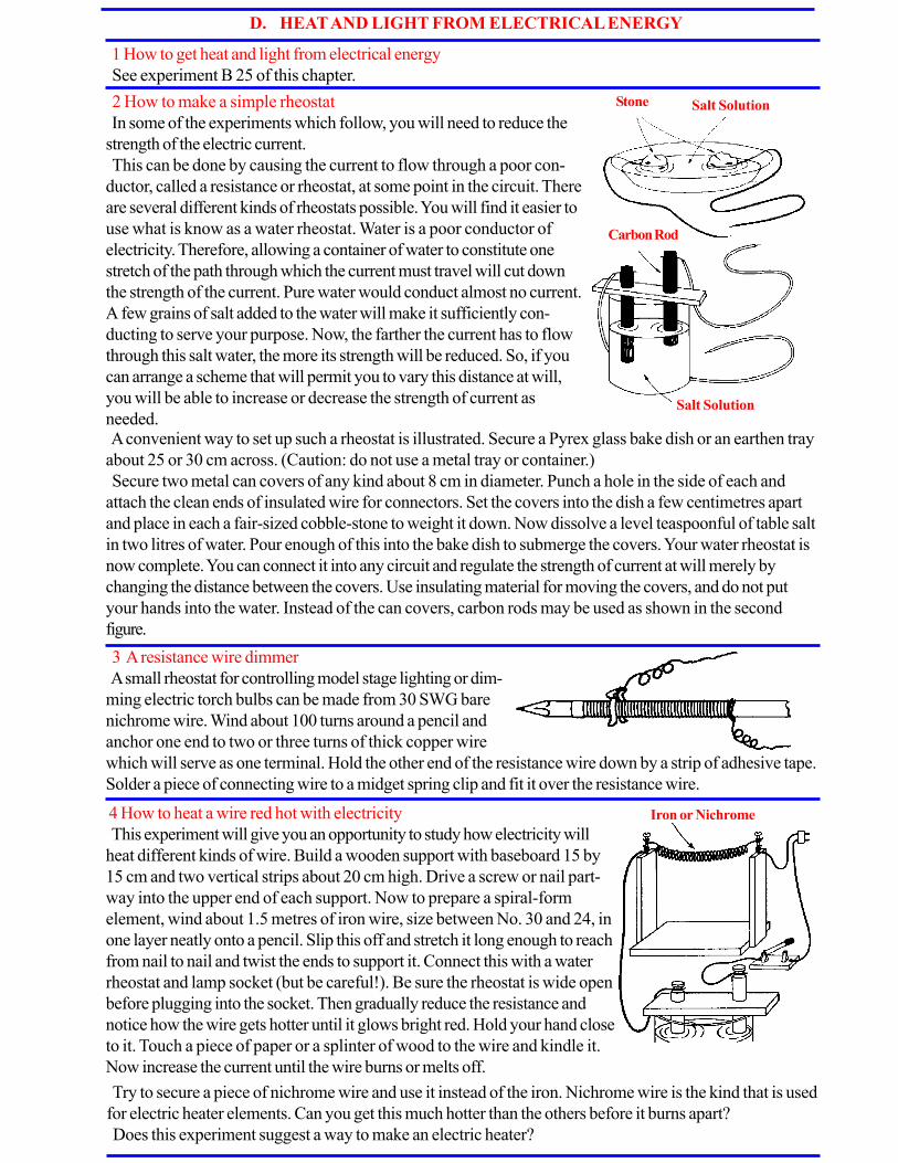
D. HEAT AND LIGHT FROM ELECTRICAL ENERGY
1 How to get heat and light from electrical energy
See experiment B 25 of this chapter.
2 How to make a simple rheostat
In some of the experiments which follow, you will need to reduce the
strength of the electric current.
This can be done by causing the current to flow through a poor con-
ductor, called a resistance or rheostat, at some point in the circuit. There
are several different kinds of rheostats possible. You will find it easier to
use what is know as a water rheostat. Water is a poor conductor of
electricity. Therefore, allowing a container of water to constitute one
stretch of the path through which the current must travel will cut down
the strength of the current. Pure water would conduct almost no current.
A few grains of salt added to the water will make it sufficiently con-
ducting to serve your purpose. Now, the farther the current has to flow
through this salt water, the more its strength will be reduced. So, if you
can arrange a scheme that will permit you to vary this distance at will,
you will be able to increase or decrease the strength of current as
needed.
3 A resistance wire dimmer
A small rheostat for controlling model stage lighting or dim-
ming electric torch bulbs can be made from 30 SWG bare
nichrome wire. Wind about 100 turns around a pencil and
anchor one end to two or three turns of thick copper wire
Stone Salt Solution
Carbon Rod
Salt Solution
A convenient way to set up such a rheostat is illustrated. Secure a Pyrex glass bake dish or an earthen tray
about 25 or 30 cm across. (Caution: do not use a metal tray or container.)
Secure two metal can covers of any kind about 8 cm in diameter. Punch a hole in the side of each and
attach the clean ends of insulated wire for connectors. Set the covers into the dish a few centimetres apart
and place in each a fair-sized cobble-stone to weight it down. Now dissolve a level teaspoonful of table salt
in two litres of water. Pour enough of this into the bake dish to submerge the covers. Your water rheostat is
now complete. You can connect it into any circuit and regulate the strength of current at will merely by
changing the distance between the covers. Use insulating material for moving the covers, and do not put
your hands into the water. Instead of the can covers, carbon rods may be used as shown in the second
figure.
which will serve as one terminal. Hold the other end of the resistance wire down by a strip of adhesive tape.
Solder a piece of connecting wire to a midget spring clip and fit it over the resistance wire.
4 How to heat a wire red hot with electricity
This experiment will give you an opportunity to study how electricity will
heat different kinds of wire. Build a wooden support with baseboard 15 by
15 cm and two vertical strips about 20 cm high. Drive a screw or nail part-
way into the upper end of each support. Now to prepare a spiral-form
element, wind about 1.5 metres of iron wire, size between No. 30 and 24, in
one layer neatly onto a pencil. Slip this off and stretch it long enough to reach
from nail to nail and twist the ends to support it. Connect this with a water
rheostat and lamp socket (but be careful!). Be sure the rheostat is wide open
before plugging into the socket. Then gradually reduce the resistance and
notice how the wire gets hotter until it glows bright red. Hold your hand close
to it. Touch a piece of paper or a splinter of wood to the wire and kindle it.
Now increase the current until the wire burns or melts off.
Iron or Nichrome
Try to secure a piece of nichrome wire and use it instead of the iron. Nichrome wire is the kind that is used
for electric heater elements. Can you get this much hotter than the others before it burns apart?
Does this experiment suggest a way to make an electric heater?
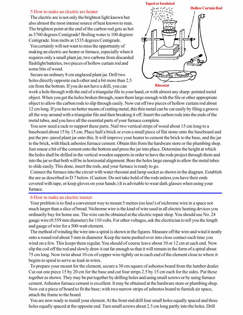
5 How to make an electric are heater
The electric are is not only the brightest light known but
also almost the most intense source of heat known to man.
The brightest point at the end of the carbon rod gets as hot
as 3760 degrees Centigrade! Boiling water is 100 degrees
Centigrade. Iron melts at 1535 degrees Centigrade.
You certainly will not want to miss the opportunity of
making an electric are heater or furnace, especially when it
requires only a small plant jar, two carbons from discarded
flashlight batteries, two pieces of hollow curtain rod and
some bits of wood.
Secure an ordinary 8 cm unglazed plant jar. Drill two
holes directly opposite each other and a bit more than 2.5
cm from the bottom. If you do not have a drill, you can Rheostat
Taped or Insulated
Hollow Curtain Rod
work a hole through with the end of a triangular file in your hand, or with almost any sharp- pointed metal
object. When you get the holes broken through, ream them large enough with the file or other appropriate
object to allow the carbon rods to slip through easily. Now cut off two pieces of hollow curtain rod about
12 cm long. If you have no better means of cutting metal, this thin metal can be cut easily by filing a groove
all the way around with a triangular file and then breaking it off. Insert the carbon rods into the ends of the
metal tubes, and you have all the essential parts of your furnace complete.
You now need a rack to support these parts. Nail two vertical strips of wood about 15 cm long to a
baseboard about 15 by 15 cm. Place half a brick or even a small piece of flat stone onto the baseboard and
put the pre- pared plant jar onto this. It will improve your heater to cement the brick to the base, and the jar
to the brick, with black asbestos furnace cement. Obtain this from the hardware store or the plumbing shop.
Just smear a bit of the cement onto the bottom and press the jar into place. Determine the height at which
the holes shall be drilled in the vertical wooden supports in order to have the rods project through them and
into the jar so that both will be in horizontal alignment. Bore the holes large enough to allow the metal tubes
to slide easily. This done, insert the rods, and your furnace is ready to go.
Connect the furnace into the circuit with water rheostat and lamp socket as shown in the diagram. Establish
the are as described in D 7 below. (Caution: Do not take hold of the rods unless you have their ends
covered with tape, or keep gloves on your hands.) It is advisable to wear dark glasses when using your
furnace.
6 How to make an electric toaster
Your problem is to find a convenient way to mount 5 metres (no less!) of nichrome wire in a space not
much larger than a slice of bread. Nichrome wire is the kind of wire used in all electric heating devices you
ordinarily buy for home use. The wire can be obtained at the electric repair shop. You should use No. 24
gauge wire (0.559 mm diameter) for 110 volts. For other voltages, ask the electrician to tell you the length
and gauge of wire for a 500-watt element.
The method of winding the wire into a spiral is shown in the figures. Measure off the wire and wind it neatly
onto a round rod about 5 mm in diameter. Keep the turns pushed over into close contact each time you
wind on a few. This keeps them regular. You should of course leave about 10 or 12 cm at each end. Now
slip the coil off the rod and slowly draw it out far enough so that it will remain in the form of a spiral about
75 cm long. Now twist about 10 cm of copper wire tightly on to each end of the element close to where it
begins to spiral to serve as lead-in wires.
To prepare your mount for the element, secure a 30 cm square of asbestos board from the lumber dealer.
Cut out one piece 15 by 20 cm for the base and cut four strips 2.5 by 15 cm each for the sides. Put these
together as shown. They may be put together by drilling holes and using small screws or by using furnace
cement. Asbestos furnace cement is excellent. It may be obtained at the hardware store or plumbing shop.
Now cut a piece of board to fit the base; with two narrow strips of asbestos board to furnish air space,
attach the frame to the board.
You are now ready to install your element. At the front end drill four small holes equally spaced and three
holes equally spaced at the opposite end. Turn small screws about 2.5 cm long partly into the holes. Drill
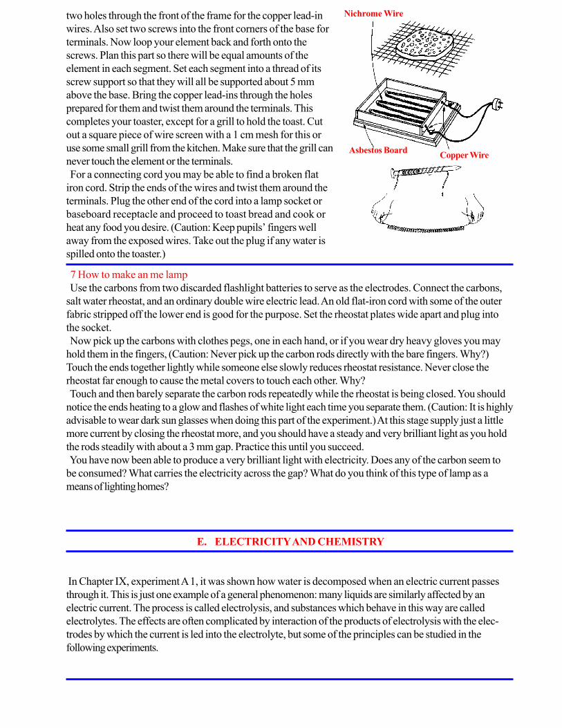
two holes through the front of the frame for the copper lead-in
wires. Also set two screws into the front corners of the base for
terminals. Now loop your element back and forth onto the
screws. Plan this part so there will be equal amounts of the
element in each segment. Set each segment into a thread of its
screw support so that they will all be supported about 5 mm
above the base. Bring the copper lead-ins through the holes
prepared for them and twist them around the terminals. This
completes your toaster, except for a grill to hold the toast. Cut
out a square piece of wire screen with a 1 cm mesh for this or
use some small grill from the kitchen. Make sure that the grill can
never touch the element or the terminals.
For a connecting cord you may be able to find a broken flat
iron cord. Strip the ends of the wires and twist them around the
terminals. Plug the other end of the cord into a lamp socket or
baseboard receptacle and proceed to toast bread and cook or
heat any food you desire. (Caution: Keep pupils’ fingers well
away from the exposed wires. Take out the plug if any water is
spilled onto the toaster.)
Nichrome Wire
Asbestos BoardCopper Wire
7 How to make an me lamp
Use the carbons from two discarded flashlight batteries to serve as the electrodes. Connect the carbons,
salt water rheostat, and an ordinary double wire electric lead. An old flat-iron cord with some of the outer
fabric stripped off the lower end is good for the purpose. Set the rheostat plates wide apart and plug into
the socket.
Now pick up the carbons with clothes pegs, one in each hand, or if you wear dry heavy gloves you may
hold them in the fingers, (Caution: Never pick up the carbon rods directly with the bare fingers. Why?)
Touch the ends together lightly while someone else slowly reduces rheostat resistance. Never close the
rheostat far enough to cause the metal covers to touch each other. Why?
Touch and then barely separate the carbon rods repeatedly while the rheostat is being closed. You should
notice the ends heating to a glow and flashes of white light each time you separate them. (Caution: It is highly
advisable to wear dark sun glasses when doing this part of the experiment.) At this stage supply just a little
more current by closing the rheostat more, and you should have a steady and very brilliant light as you hold
the rods steadily with about a 3 mm gap. Practice this until you succeed.
You have now been able to produce a very brilliant light with electricity. Does any of the carbon seem to
be consumed? What carries the electricity across the gap? What do you think of this type of lamp as a
means of lighting homes?
E. ELECTRICITY AND CHEMISTRY
In Chapter IX, experiment A 1, it was shown how water is decomposed when an electric current passes
through it. This is just one example of a general phenomenon: many liquids are similarly affected by an
electric current. The process is called electrolysis, and substances which behave in this way are called
electrolytes. The effects are often complicated by interaction of the products of electrolysis with the elec-
trodes by which the current is led into the electrolyte, but some of the principles can be studied in the
following experiments.

1 Conduction effects in different types of liquids
Liquids can be divided into different chemical classes. The
following can easily be studied: (a) distilled water, oils,
methylated spirit; (b) acids and alkalis, e.g. dilute sulphuric
acid, dilute hydrochloric sulphate and silver nitrate.
Obtain two small carbon rods from an old torch battery and
pass them through holes about 2.5 cm apart in a strip of
wood 2.5 cm wide and 10 cm long. Solder copper wires to
the brass caps and join up a series circuit as shown in the
diagram, using a 6 volt dry battery as current supply and a 2.5
volt bulb as current detector.
Put the liquid under test in a small jar and immerse the rods.
You will find that some of the liquids do not conduct elec-
tricity, gases are released from others, and that in some cases
changes take place on the surfaces of the rods.
2 Collecting the gaseous products of electrolysis
If the gases released by electrolysis are collected separately they can be identified. A simple apparatus for
doing this, called a voltameter, can be constructed using an ice-cream carton as container for the liquid,
carbon rods as electrodes, and small glass test tubes or tubular pill bottles for collecting the gases. Solder
copper wires to the carbon rods as before, and fit them through the holes made with a cork borer in the
bottom of two cartons; the second carton is used as a stand for the apparatus. Hold the two carton bottoms
together, and using balsa wood or other cement, seal the rods in position with about 2.5 cm protruding into
the upper cup. Pass connecting wires through holes in the side of the lower cup. Pour dilute hydrochloric
acid into the upper cup and fill the glass tubes with it, inverting one over each carbon rod. Connect the wires
to a 6-volt dry battery as before and wait for results. As chlorine is soluble, it is necessary to wait until the
solution is saturated, but finally equal volumes of hydrogen and chlorine will be collected.
3 To make a bleaching solution by electrolysis
Make a strong solution of common salt by dissolving as much as possible in half a tumbler of water. Fit a
cardboard wedge between the carbon rods of the voltameter used in the last experiment, thus dividing it into
two equal compartments. Pour in the salt solution, and put a piece of red litmus paper in each compartment.
Connect the rods to a grid bias battery, using 7.5 volts. Bubbles of hydrogen will immediately be released at
the cathode (negative) but no chlorine will appear at the anode (positive) for the reason given in the last
section. After about twenty minutes, however, the litmus paper in the anode compartment will be bleached,
while in the cathode compartment the paper will turn blue owing to the formation of sodium hydroxide.
When bubbles of chlorine appear, stop the current, remove the wedge, and stir up the liquid. Sodium
hypochlorite will then be produced. This is the compound contained in commercial bleaching fluids; examine
its effect on a test tube of water coloured with a drop of ink.
4 To examine the electrolysis of special solutions: (a) zinc sulphate; (b) lead acetate
(a) Pour a weak solution of zinc sulphate into the voltameter and electrolyse it, using a 9-volt grid bias
battery. Almost immediately a spongy mass of zinc appears on the cathode.
(b) Add a few grams of lead acetate to half a tumbler of water. To remove cloudiness, stir the solution with
a glass rod which has been dipped in acetic acid. Pour the liquid into the voltameter and connect to a
battery as before. Lead quickly deposits on the cathode in the form of a ‘tree’ which is fascinating to watch
as it grows.

5 To study the action of a simple lead accumulator
From a sheet of lead about 1.5 mm thick cut strips 15 cm long and
about 15 mm wide for use as plates of the cell. Punch holes near the
end of each plate and thread through copper connecting wires. Wash
the plates in water and clean them with steel wool or emery cloth.
Put them into a boiling tube containing a little dilute sulphuric acid
and separate them by a wooden splint. Also bend over the tops of
the plates so that they can never touch one other. First transform
these plates into spongy lead and lead peroxide respectively by
passing current from a 6-volt dry battery. After a few minutes one of
the plates becomes a red-brown colour, whilst the other remains
grey. When this has happened disconnect the battery and connect in
its place a 2 volt torch bulb. If the bulb does not light, join the plates
to the battery al2ain for a few more minutes and then carry out the
test.
6 How to make a more serviceable accumulator
The preceding way of forming the plates is only suitable for
demonstration purposes.
To make a working accumulator, larger and thicker plates must
be used, and chemicals must be embedded in holes drilled in the
plates.
Use lead sheet about 5 mm thick—old gas or water pipe ham-
mered out will do. Prepare plates of the dimensions shown, with
holes drilled in them, and fill up the holes with the following pastes:
Now arrange a circuit as shown so that the plates can be charged and discharged through the bulb at the
turn of a switch. Connect the battery for one minute, then discharge through the bulb, noticing the time in
seconds that the bulb remains alight. Repeat this experiment, charging in turn for 2, 3, and 4 minutes and
recording the time taken to discharge through the bulb.
As a further test take a few more readings with the plates half immersed in acid. Put a thermometer in the
acid and notice if there is any change in temperature after charging for some time. If facilities are available,
try to detect any change in the density of the acid after charging for half an hour.
Positive plate 1 part litharge. 4 parts red lead. 1 part sulphuric acid.
Negative plate 6 parts litharge. 1 part sulphuric acid.
Separators of wood, about 5 mm thick, the same as before but with holes drilled in them, will be required.
Assemble the plates by fastening the two negative plates together and holding in the separators, etc., by a
rubber band, or a piece of string. Insert the whole into a jam jar filled with dilute sulphuric acid (S.G. 1.5),
so as to just cover the plates.
The cell should be charged as before. When charged, the positive plate will be a red- chocolate colour,
and the negative plate a light grey.

7 Electro-plating nickel and copper
Electro-plating is now familiar to everyone. It is done by forming a layer of metal on the object which is
used as a cathode in a voltameter containing a salt of the metal to be deposited. To get lasting results the
object must be carefully cleaned and degreased; the correct anode must be used, and the solution must be
carefully prepared and used at a temperature of about 50C. The copper anode used for copper plating and
the nickel anode for nickel plating need only be degreased.
The following baths have proved satisfactory.
Copper Nickel
Cupric Sulphate 200g Nickel Sulphate 240g
Sulphulic Acid 60 g Nickel chloride 54 g
Water up to 1000 ml Boric acid 30 g
Water up to 1000 ml
Copper plating. Pour the electrolyte into a jar and immerse in it a strip of copper which serves as an
anode. Clean a sheet of brass with fine emery cloth, and degrease it with a mixture of magnesia and water
on a wad of cotton wool. Rinse it in water, immerse it in the bath and connect it to the negative terminal of a
3-volt torch battery. Complete the circuit by joining the anode to the positive pole of the battery. Note the
deposit of copper produced. Too heavy a current may result in a spongy deposit; the correct value for a
hard deposit is 4 amperes per 100 cm2 of area.
Nickel plating. Use a strip of copper as a cathode, cleaning and degreasing it as before. A nickel spatula
can be used as an anode, but if this is not available a strip of lead may be used; this will mean that the
electrolyte becomes weaker during use. Join up to the battery as before, when a good deposit of nickel will
be obtained. The surface, after washing, can be polished using jewellers’ rouge or cigarette ash on a piece
of soft cloth.
8 To copy a scout badge or medal by electrolysis
This process, called electrotyping, is much used in industry. A
mould is made of the object to be copied. This is then made
conductive by various methods and a shell of this impression is
made by depositing copper on it electrolytically. The object is
removed from the mould, and the copy is strengthened by
pouring type metal into it.
First warm the badge in a clean Bunsen flame and make an
impression on the end of a short piece of candle or alkaline
rod. Make the surface of the mould conducting by scraping
some lead from a pencil over it, or by coating it with colloidal
“BE A GOOD SCIENTIST. FOLLOW INSTRUCTIONS EXTREMELY CAREFULLY.
WEAR PROTECTIVE CLOTHING WHEN WORKING ON ANY EXPERIMENTS
THAT INVOLVE FIRE OR EXPLOSIONS.”
graphite. Another way to do this is to scatter some iron filings over it after moistening it with copper sul-
phate; the copper will displace the iron and cover the surface of the mould with a layer of copper. Now heat
a, piece of copper wire and press it into the wax in such a way that connection is made to the conducting
surface without disfiguring the shape. Use the wire to hang the mould in a copper-plating bath. Also suspend
a strip of copper in the solution to serve as an anode, facing the mould. Connect to a 3-volt torch battery
through a small rheostat and leave it overnight. The next day a good strong layer of copper will have been
deposited. Strip this from the mould, and if necessary strengthen it by pouring molten solder into the back of
the shell. Trim the badge with a pocket knife and solder a safety pin to the back. If desired it can now be
plated as in the last experiment.

CHAPTER XVI
Experiments and materials for the study of light
A. LIGHT TRAVELS IN A STRAIGHT LINE
1 Making tracks
Find a dusty road or a sandy beach. Fix your eyes on a distant object and walk towards it without chang-
ing your line of vision. Now observe the tracks you have made, and you will see that you have been follow-
ing a straight line.
2 With a string
Obtain a piece of string that is at least 25 metres in length. Fasten one end of the string to a post or a tree.
Pull the string taut and hold it to the eye. Look along the string, and you will see the object to which it is
fastened. Now look in another direction, not along the string, and you do not see the object. This shows that
light comes to the eye from such objects in a straight line.
3 An experiment with cards
Cut four pieces of cardboard about 10 cm square. Tack them to small wood blocks so that they will stand
upright. Punch a small hole through each card at exactly the same place so that when the cards are set up
and arranged in a straight line you can look straight through all four holes. Place a candle dame so that it can
be seen by looking through all the cards spaced about 30 cm apart. Now pull one of the cards a little out of
line with the others and try to look through them at the candle flame. Can you see it? Why not? What does
this show?
4 A pinhole camera
A simple pinhole camera can be made by making a fine hole in
the bottom of a tin and receiving the image on tissue paper,
stretched across the top of the tin. Roll a sheet of brown paper
round the tin so that a tube projects and shields the tissue paper.
This will keep daylight from the screen, and enable an image of a
window or candle dame to be observed. What do you notice
about the image? How does this show that light travels in straight
lines?
5 Making a smoke box to study light rays
Obtain or construct a wooden box about 30 cm wide and
about 60 cm in length. Fit panes of window glass in the top
and front of the box. Leave the back open, as shown in the
diagram, and cover with loosely hung black cloth which
drapes like a curtain. Hang this curtain in two sections
making about a 10 cm overlap at the centre of the box.
Paint the inside of the box with matt black paint. About
midway between the top and bottom of one end and about
8 or 10 cm from the glass front, cut a window 10 cm long
and 5 cm wide. This is to let in light rays. You can cover the
window with different kinds of openings cut from cardboard
and fastened with drawing pins.
White Card About One Meter
Glass Top and Front
Black
Cloth
For the first experiment cut a piece of black cardboard with three equidistant holes about 5 mm in diam-
eter. Fix over the window with drawing pins. Fill your box with smoke. This can be done with dry rotten
wood, incense candles or smouldering cigarettes placed in a dish and set in one corner of the box. Next set
up an electric torch about one metre from the window. Focus the light down to a parallel beam and direct it
at the holes in the window. Observe the light rays in the box made visible by the smoke. Does this experi-
ment show that light travels in straight lines ?

B. THE REFLECTION OF LIGHT
1 Regular reflection with the smoke box
Fill the smoke box with smoke. Shine the torch beam on the
three holes in the window as in the last experiment. Now hold a
plane mirror inside the box and observe how clearly the rays
are still defined after reflection from the mirror. When light rays
are thus reflected without scattering they are said to be regularly
reflected.
2 Diffuse reflection with the smoke box
Place a piece of clear cellophane on a pane of
glass and roughen it by rubbing with a piece of steel
wool until the surface has a uniformly dull appear-
ance. Fix the piece of dulled cellophane to the
glass with glue or rubber bands. Hold in the beam
of the torch inside the smoke box and observe the
results. Compare with the regular reflection in the
previous experiment. When light is scattered by
reflection from an irregular surface it is called
diffuse reflection. Place your eye in direct line with
the reflected beam from a mirror. Repeat, using the
dulled cellophane reflector. Observe and describe
the differences.
3 Reflection with a rubber ball
Study reflection from a door or wall by bouncing a rubber ball straight and at angles to the reflecting
surface. Try to observe and compare the angle at which the ball strikes the surface with the angle at which it
is reflected.
4 Reflection with a mirror
Place a plane mirror on the floor where a beam of sunlight will strike it and be reflected. Stand a drinking
straw upright at the place where the beam strikes the mirror. Compare the angle made by the incident beam
and the straw with the angle made by the reflected beam and the straw.
5 Making reflected beams of light
Hold a comb in a sunbeam falling on a piece of white
cardboard. Tilt the cardboard so that the beams of light
are several centimetres long. Place a mirror diagonally in
the path. Observe that the beams which strike the mirror
are reflected at the same angle. Turn the mirror and
observe how the reflected beams turn.
Rough Surface
Diffuse Reflection
No Eye Glare
About One Meter
Smooth Surface
Regular Reflection
Bright Glare
From Lamp
Beams of Sunlight
Shining Through Comb
Mirror
Reflected Beam
6 How to make a sighting stool for the study of reflected light
Though ‘pin optics’ are rather out of fashion at the moment, this
method is capable of yielding accurate results. Confusion often arises
with juniors because pins are used both as object and to track rays of
light. This confusion is avoided if sighting stools are used in the first
experiments. A piece of tin, 12 by 1.5 cm, is bent in the form of a
stool; the ends form legs and a slit is cut with a hacksaw blade in each
of them. A pin is used as object, and its image is sighted through the
slits. Pencil marks are then made to track down the path of the light.

7 The laws of reflection
Draw a broken line on a piece of paper with a ruler. Next draw a straight
line from it at any angle. Set a small mirror upright at the point where the
two lines meet. Turn the mirror until the reflection of the dotted line is in
line with the real dotted line. Now look into the mirror and line up one
edge of your ruler with the reflection of the straight line. Draw this line with
your pencil and measure the angles on each side of the broken line with a
protractor.
8 How to make a cylindrical lens for a ray box
File down the edges of a piece of Perspex or lucite 5
by 3 by 6 cm. Grind it by using the inside of a can with a
layer of emery paper glued inside.
Final polishing is done with metal polish and cotton
wool. Protractor
9 How to make a ray box for beams of light
The cylindrical lens described in experiment B 8 above can be
used in a ray box. This apparatus consists of two sides of an
oblong box 22 by 6 cm held together in this case by 2 BA rod,
with the lens placed at one end of the box. The box has no
bottom, and in use rests on paper pinned to a drawing board.
The light source is a 12-volt 24-watt automobile lamp. The
lamp holder has a sleeve of brass tubing just fitting in a hole in a
wooden slide, which forms the top of the box. The groove in
10 Laws of reflection with a ray box
A slip of mirror can be made to stand vertical by inserting
one end in a piece of cork with a groove in it, or in a
paperclip. Beams of light shone along the paper are marked
by crosses. The incident, and reflected rays, and the normal,
are recorded by joining up the crosses by pencil lines.
Mirror
Ruler
Repeat this experiment several times, changing the size of the angle each time. The evidence should show
that light is always reflected at the angle at which it strikes the
front of the lens is for screens and filters. A piece of card with a slit in it provides narrow rays and a painter’s
graining comb will give a bundle of rays. Convergent, parallel or divergent beams are obtained by adjusting
the position of the slider. Ah the usual experiments with rays can be performed using slips of plane mirror,
glass blocks and prisms. A curved piece of tin will show a caustic curve.
In experiments with lenses and in refraction, the lamp should be pushed down as far as possible so that the
light does not pass over the top of the obstacle. A card with a hole and cross wires can be used in front of
the lens, as a source for optical bench experiments.
11 A simple optical disc Obtain a shallow can of roughly the same diameter as an ordinary protractor. Cut out
a piece of white card to put on the top of the can: glue it down and mark degrees on it.
Fix a strip of mirror to a small block of wood and mount it on a nail which fits loosely
through a hole in the centre of the scale and the can. Cut a narrow slit in a rectangular
sheet of metal as shown in the diagram, and bend the sheet round the circumference of
r the can, fixing it in position so that the slit is opposite the 900 mark on the circular
scale. Place the can on the bench so that the sun or a distant source of light throws a
ray which passes through the slit to the centre of the scale. Adjust the mirror so that
the light is reflected along its own path. Now rotate the mirror through 100. What do
you notice about the angle through which the reflected ray is turned?

12a A mirror on a stick
Fasten a mirror to the end
of a ruler with a paperclip.
Stand on one side of a door
and hold the mirror outside
the door opening. Explain
how reflected light enables
you to see around the
corner.
13 How to make a model periscope
Score three lines parallel to the long side of a postcard and 2 cm
apart. These will divide the card into four strips. Cut away pieces
from the ends 2 cm wide as shown in the diagram. Cut holes in the
positions shown, using a cork borer, and then fold up the card into
a rectangular box. Stick small pieces of mirror opposite the aper-
tures, using plasticine or gummed paper.
14 How to make a kaleidoscope
Fasten together two slips of mirror about 10 cm by 3 cm and a
piece of card the same size, with a rubber band or gummed
paper. Look down the axis of the triangular prism so formed.
Objects viewed through it will form a regular pattern. If silvered
glass is not available, black paint on the outer side of plain glass
will give quite good results.
15 Double reflection
Cut a slit about 1 cm wide in one end of a small
cardboard box. Be sure to cut the slit all the way to the
bottom of the box. Set the box on one side and place it
in bright sunlight. Adjust the box so that the beam of
sunlight falls along the bottom of the box and place
mirrors as shown in the diagram.
16 Reversed writing
Produce reversed writing by placing a piece of carbon paper, carbon side up,
under a sheet of plain paper. Write something on the paper and you will have
reversed writing on the other side. Read the reversed writing by holding it in
front of a mirror. Write some thing while you look in the mirror at the paper and
watch the pencil.
17 Copying drawings by reflection
Use a wooden clothes peg to support a sheet of clear glass verti-
cally on the bench. Place the drawing to be copied on one side of the
glass and a piece of white paper on the other. Look through the glass
at the white paper and draw over the reflection of the drawing. Why
must the glass be vertical? How does the copy differ from the
original? Why is it an improvement to shield daylight from the paper
you are drawing on?
Light Beam Sunlight
Reflected Beam
Second Reflected
Beam
Slit in a Box
Mirror
Second Mirror
12b The clock face and a mirror
Stand two mirrors at right angles to
each other with their edges touching.
These edges may be joined with strips
of tape. Place a clock in front of the
mirror with the midline of its face
opposite the junction of the two mirrors.
Observe the image and compare with
the image seen with a single mirror.

19 Making money with reflection
Hinge two mirrors together with a piece of tape and set them up as
shown in the diagram. Place a coin between the mirrors and observe the
number of images formed. See if you can increase the number of images
by varying the angle of the mirrors. Place a lighted candle between the
mirrors and observe the images.
20 Reflection with parallel mirrors
Stand two mirrors on edge with the reflecting surfaces facing
each other. Place a coin or a lighted candle between the mirrors.
Look in one mirror and see how many images are formed. Look
in the other mirror.
21 Reflection from a concave mirror with a ray box
Use the ray box constructed in experiment B 9 above. The focal length can be measured directly by
directing a parallel beam of light on to a curved strip of tin, or a part of a metal ring.
22 Reflection from a convex surface
Obtain a convex mirror such as an automobile wing mirror. Use this with the ray box and observe the
reflected rays of light. Compare with the reflection from a plane mirror and a concave mirror.
Coin
Coin
Mirrors
C. THE REFRACTION OF LIGHT AND ITS USES
1 The stick appears to bend
Place a stick in a tall jar of water, so that part of the stick is above the surface. Observe where the stick
enters the water and appears to be bent. This is caused by the bending or refracting of the light rays as they
reach the air from the water. Light travels faster in air than in water and so is bent slightly when it passes
from one medium to the other.
2 Refraction in a beam of light
Pour a few drops of milk into a glass of water in order to
cloud the water. Punch a small hole in a piece of dark paper
or cardboard. Place the glass in direct sunlight. Hold the
card in front of the glass. A beam of sunlight will shine
through the hole. Hold the card so that the hole is just
below the water level and observe the direction of the beam
in the water. Now raise the card until the beam strikes the
surface. Observe the direction of the beam of light. Experi-
ment to find out how the angle at which the beam strikes the
water affects the direction of the beam in the water.
Hole Below
Water
Surface
Place of black paper
with hole in centreHole above water surface
Glass of water with
drops of milk

3 How to make a refraction bottle
Paint the outside of a medicine bottle black. Scratch a circle off one
side and fill the bottle with water until the surface is just level with the
centre of this circle. Shine a beam of light through the top of the
bottle (the paint should be removed from a small area). A drop of
milk in the water will make the beam show up better. The angles of
incidence and refraction are now measured with a protractor.
4 Refraction shown with the smoke box
Over the window of the smoke box (see experiment A 5 above) fasten a piece of black cardboard with a
single hole in it about 8 mm square. Arrange the torch to shine a beam of light into the box as in previous
experiments. Fill a large rectangular bottle with water and add a few drops of milk or a pinch of starch or
flour to make the water cloudy. Cork the bottle. Fill the box with smoke. Hold the bottle at right angles to
the beam of light and observe the direction of the light through the water. Next tilt the vision so that the edge
of the cup just interferes with your seeing the coin in the bottom. Hold this position while another person
pours water carefully into the cup. What do you observe? How do you account for this?
6 How a prism affects light rays
Use the smoke box exactly as you did for experiment C 4 above. Hold a glass prism in the single beam of
light and observe how the beam is refracted.
7 How lenses affect light rays
For these experiments, you can take the lenses from an old pair of spectacles or used optical instruments,
or purchase reading glass lenses and hand magnifiers.
Cover the window of the smoke box with a piece of black cardboard in which you have punched three
holes. The holes should be the same distance apart, but the distance between the two outside holes should
be a little less than the diameter of your lens. Arrange the torch to supply the light rays as in previous experi-
ments. Fill the box with smoke and hold a double’ convex lens in the path of the three beams of light so that
the middle beam strikes the centre of the lens. Observe the beams on the opposite side of the lens from the
source of light. How are they affected ?
Repeat the experiment using a double concave lens. Compare the observations made in this experiment
with those made in experiment C 6 above. Think of the double convex lens as made up of two prisms put
together base to base and the double concave lens as two prisms put together tip to tip.
8 Rough lenses from bottle bottoms
Bottles can be found with convex or concave bottoms. These can be cut off by any of the methods indi-
cated (page 218) and the rough edges removed by rubbing on a stone surface. Whilst rarely good enough
to provide a clear image, They can be used to illustrate how bush fires may be Started by old bottles lying
in dry grass, etc. and focusing the sun’s rays.
9 How lenses magnify
Dip a pencil (or your finger) into a glass of water, and look at it
from the side. Is it magnified? Observe a fish in a fish bowl, looking
at it from the top and from the side. Do the bowl and the water
magnify the fish? Observe olives or other things placed in circular
jars.Are they magnified? Clear glass marbles act as lenses also.
5 Making a coin appear with refraction
Place a coin in the bottom of a teacup on a table. Stand away
and arrange your line of vision so that the edge of the cup just
interferes with your seeing the coin in the bottom. Hold this
positionwhile another person pours water carefully into the cup.
What do you observe? How do you account for it?

10 How to measure the magnifying power of a lens
Focus a hand lens over some lined paper. Compare the number of spaces
seen outside the lens with a single space seen through the lens. The lens
shown in the diagram magnifies three times.
11 How a convex lens forms a picture image
Darken all the windows in a room but one. Have a pupil hold a lens in
the window directed at the scene outside. Bring a piece of white paper
slowly near the lens until the image picture is formed. What do you
observe about the position of the image?
12 How to make a simple apparatus to study lenses
All that is needed for an optical bench is a firm surface, a way of
holding mirrors and lenses, and a convenient way of measuring
distances.
A metre scale laid hat on the bench serves as the basis of this simple
apparatus. Wooden blocks, with grooves that just fit over the scale,
can be adapted as holders. A layer of cork or soft cardboard glued
on the top makes it easy to stick pins, such as object and search pins,
into each block; strips of tin screwed to the side make convenient lens
holders. A groove in the top of a block helps to keep the lens in
position, and rubber tubing over the tin increases the grip.
Light sources and screens can be improvised with card and torch
bulbs fastened to the blocks. It is worth while to make complete sets
of this apparatus so that individual work on lenses can be attempted.
The groove is easy to make with a chisel after two sawcuts have been
made in the wood.
Many other experiments, for instance on interference and diffraction,
can be attempted using this apparatus.
13 A simple microscope
Make a single turn of copper wire around a nail to form a loop. Dip the
loop into water and look through it. You will have a microscope like the
earliest ones used. Often such a lens will magnify four or five times.
If you tap the wire sharply against the edge of the glass a drop of water will
fall off. Because of adhesion between the wire and the water, the liquid
remaining will form a lens which is very thin at the centre, i.e., a concave lens.
14 A water drop microscope
Place a drop of water carefully on glass. Bring your eye close to the look at something small through drop
and glass. This serves as microscope.
White Card
Hand
Lens
Window
Nail
Thin Wire
Lens
15 A model compound microscope
Arrange a short focus lens on the optical bench made in experiment C 12. Place a lighted candle behind a
piece of window screen on one side of the lens. On the other side of the lens place a white cardboard sheet
at the point where the dearest image of the screen is formed. Remove the cardboard sheet and place
another double convex lens slightly farther away than where the cardboard was. Look through both lenses
at the screen. It will appear enlarged.

16 A model refracting telescope
Arrange a long focus lens on the end of the optical bench pointing at some scene through a window. As in
the previous experiment, bring a white cardboard up on the opposite side of the lens to the place where the
sharpest image of the scene is formed. Now bring a short focus lens up behind the cardboard until the
cardboard is a little nearer the lens than its focal length. Remove the cardboard and look through the two
lenses at the scene.
17 How to make a line light source
A bulb as used in direction indicators and interior car lights provides
a useful line source of light for optical experiments. A convenient
holder can be made from a piece of plywood. Strips of tin tacked
to the wood, or held by screw terminals, can be used to make
electrical connection
18 Image and object relationships for a lens
The lens can be fastened to the front of a wooden block
with plasticine. The image position is where the rays cross.
It is interesting to plot a against v and test the formula
1 / u + 1 / v = 1 / f
19 Image and object relation for a lens (without source)
A piece of mirror about 5 cm square can re- place a source of
light. The object is then a 1 cm square at the centre of the mirror
from which the silvering has been removed.
The mirror should face the light, when the image can be caught
on a piece of cardboard on the side away from the light.
The relationship can also be tested.
20 Critical angle
Make an air cell from two microscope slides by cutting a tinfoil
frame and sticking it between the slides with Canada balsam or
Bostik cement.
Fit this in a slot in a piece of wood about 20 cm long. Push knitting
needles through the ends of the wood to act as pointers, indicating
the position of the lath.
When this rod rests on a beaker of water with the air cell inside it,
the needles should just touch the paper on which the beaker stands.
This is the critical angle apparatus.
In use a base line of three pins is used, a diameter of the beaker.
The rod is moved until total reflection occurs. There will be two
positions for this, and the points of the needle should be marked in
each case.
image size
object size
21 To measure the critical angle for water
Cut a disk 4 cm in diameter from a piece of waxed cardboard.
Pass a long pin through the centre of the card and float it head
downwards in a vessel of water. Viewing the pinhead from above the
surface it will be found that its position can be adjusted until it just
disappears behind the card. In this position, a ray of light from the
pinhead is refracted so that it passes along the surface and cannot
reach the eye.
The angle a can be measured directly or by measuring (CE / CH)
and using tangent tables.

22 Another critical angle experiment
Put a small specimen tube or pill bottle in a rectangular glass
tank, and look through the sides. The centre part of the tube will
act as a cylindrical diverging lens, but the edges will appear to
be silvered.
From the ray diagram it will be seen that sin C = ( d / r )
These two distances can be measured by using sighting stools
with their ends against a ruler parallel to the face of the tank.
23 How a camera works
Secure two boxes which will telescope over one another
rather tightly. Cut one end out of each box and slip the boxes
over each other, with the cut ends together. Now cut the back
end from one box and fit a piece of grease- proof or tissue
paper over it. Cut a hole the size of a lens in the other end and
fix a convex lens in the hole. Now move the boxes in and out
until the lens focuses an image of an outside scene on the paper
screen. In a camera the sensitive film is placed where the paper
is on the model.
24 How to take a picture with a pin- hole camera
Make a pinhole camera (see experiment A 4 of this chapter)
from a wooden box such as a chalk box. Paint the inside black.
Bore a 1 cm hole in the centre of one end. On the inside of the
box cover the hole with a piece of thin metal foil. With a needle
punch a hole in the centre of the metal foil and be sure that the
25 A simple view camera
A simple view camera can be made as follows. With a hand lens focus the image of
a distant hill or tree on a card. Measure the distance between the lens and the card
and cut down a small carton so that its height equals this distance. In the centre of
the bottom cut a hole a little smaller than the lens. Fix the lens over this hole with a
piece of cardboard containing a hole the same size as the first. Tie a sheet of thin
tissue paper over the open top of the box. This view camera may be used in a
darkened room with the lens directed towards a window.
26 A focusing view camera
A focusing view camera can be made in much the same way as one
described in experiment C 25. A second box telescopes into the first to
allow focusing. The brighter the object viewed and the darker the screen of
tissue paper, the better the results will be.
Guides
Film
Cork
hole is very neat. Inside the opposite end of the box fit some guides, into which you can slide sections of cut
film. Fit a cork tightly in the hole to cover the pinhole. In a dark room cut some photographic film to the
proper size to slide into the guides. Cover the top of the box and take your camera outside. Point it at the
scene you wish to take a picture of. Remove the cork for a second or two and replace it. In the dark room
remove the exposed him and develop it or wrap it in black paper and take it to a photographic shop for
developing.
Lens
Thin
Paper
Rubber Bands
Rubber BandsThin
Paper

D. EXPERIMENTS WITH COLOUR
1 What is the colour of sunlight?
Darken a room into which the sun is shining. Punch a small hole
in the window shade to admit a thin beam of light. Hold a glass
prism in the beam of light and observe the band of colours, called
a spectrum, on the opposite wall or ceiling. Can you name the
colours thus found in a spectrum of the sun?
2 Potting spectrum colours together
Hold a reading glass lens in the colour band on the opposite side of the prism from the white sunlight. What
happens to the colour band on the wall?
3 Another way to make a spectrum
Set a tray of water in bright sunlight. Lean a. rectangular pocket
mirror against an inside edge and adjust it so that a colour band or
spectrum appears on the wall.
4 Studying a spectrum with the ray box
A glass prism will produce a good spectrum from a parallel
beam of light using a ray box. In front of the lens the ray box
should have a narrow slit, which can be cut from a piece of
card. Interposing coloured gelatine filters and packing papers in
the beam will suppress certain colours. For instance, when a
trans- parent purple paper is used, only red and blue lines will
be seen on the screen.
5 How to see a line spectrum
To make a simple optical slit scratch some silver off the back of a
mirror with a needle, or remove in the same way some of the emul-
sion from a fogged photographic plate. For viewing a line spectrum,
the slit can be replaced by a needle held parallel to the refracting
edge of the prism, and illuminated by the light under examination.
SpectrumGlass Prism
Spectrum Colours
Sunrays
Mirror
Tray of Water
6 How to make a rainbow
Stand a tumbler very full of water on a window ledge in bright sunlight.
Let it project a little over the inside edge of the window ledge. Place a
sheet of white paper on the floor and you will be able to see a rainbow
or spectrum band.
7 Another way to make a rainbow
Early in the morning or late in the afternoon of a bright sunny day, spray water from a hose against a dark
background of trees with your back toward the sun. You will see a lovely rainbow.

8 The colour of transparent objects
Use the smoke box (see experiment A 5 above) as in previous experiments. Have a single ray of light enter
the box. Hold a clear sheet of glass or cellophane in the beam of light and note that the beam on the white
screen in the box is white. Next hold a sheet of red glass or cellophane in the white beam and observe that
the beam which reaches the white screen is red. All the other colours of the white light have been absorbed
by the red. Experiment with other coloured transparent sheets. You will observe that such objects have
colour due to the colours they transmit and that they absorb other colours.
9 The colour of opaque objects
Get a good spectrum on a wall or a sheet of white paper in a darkened room. Place a piece of red cloth in
the blue light of the spectrum. What colour is it? Place it in the green and in the yellow. How does it appear?
Place it in the red light. How does it appear? Repeat using blue, green and yellow coloured cloth. You will
observe that they appear black except when placed in the same coloured light. Thus opaque objects have
colour because of the light they reflect; they absorb the other colours of the spectrum.
10 Mixing coloured pigments
Take a piece of blue chalk and a piece of yellow chalk. Crush them and mix them. The resulting colour is
green. These are not pure colour pigments. Notice that green is between yellow and blue in the spectrum.
The yellow absorbs all colours but yellow and green. The blue absorbs all colours but blue and green; thus
the yellow and blue absorb each other. and the green is reflected to the eye.
Try the same experiment by mixing paints from a painter’s box.
11 Mixing coloured lights
(a) Mixing of coloured lights can be achieved by using water colours painted on disks of cardboard.
One suggestion is to paint a yellow ‘egg yolk’ on one side of a 10 cm disk, and a blue ‘yolk’ on the other
side. When the disk is suspended by short pieces of string, and twirled between the fingers and thumbs, the
result is nearly white, if the colours are carefully chosen.
Other colour mixtures can be investigated in a way similar to that used on the toy ‘colour tops’. Radial
segments are painted, say, alternately red and green. The resulting mixture of red and green lights reflected
to the eye by spinning the disk on string is, of course, yellow in this case.
(b) Three of the boxes described for experiments on rays in elementary optics can also be used for mixing
coloured lights. Any similar box containing a car bulb will serve the same purpose.
Place red, green and blue theatrical filters in the front of the box and cast rectangular patches of light on a
white screen.
Red and green give yellow.
Blue and red give purple.
Green and blue give peacock blue.
Red, green and blue give white.
Red Beam White Beam
Red Spot Red Glass or
Cellophane
Red Light
White
Light
White
Light
White
Light
Red Glass or Cellophane Clear Glass

12 Colours in a soap film
Make a strong soap solution such as would be used for blowing soap bubbles. Fill a flat dish with the
solution and dip an egg cup or a tea cup into the solution until a film forms across the cup. Hold this in a
strong light and observe the colours you can see. Thin films often have colours.
13 Colours in an oil film
Fill a shallow dish with water. Colour the water with black ink until it is very dark. Put the dish in a window
where light from the sky is very bright, but not in direct sunlight. Look into the water so that light from the
sky is reflected to your eye. While looking at the water place a drop of oil or gasoline on the surface at the
edge of the dish nearest to you. You should see a brilliant rainbow of colours flash away from you toward
the opposite edge. By blowing on the surface you will observe a change in the colours.
14 Colours from a feather
Look at a distant candle flame through the end of a feather. You should see two or three candle flames on
each side of the actual flame and a flattened X with four coloured arms. If the feather is good you will see
two blue and red bands in each of the four arms.
15 How colours change
Paste some coloured illustrations from a magazine on a piece of cardboard. Pour three tablespoonfuls of
salt in a saucer and add several tablespoonfuls of alcohol. Mix and light. This produces a very brilliant light
that gives out only yellow. View the picture in this light in a darkened room and observe how all colours but
the yellow change.
E. OPTICAL PROJECTION
In order to produce a good image or picture on a screen, a lens must be of good quality. A magnifying glass
may be used, but better results are obtained with an old camera lens. Used in this way the lens is called the
‘objective’ or object lens, and the magnification obtained depends on its focal length.
Opaque objects must be strongly illuminated because only the light reflected from the surface will pass
through the lens. Transparencies can be illuminated from behind; in this case an extra ‘condensing’ lens is
used behind the slide or film to ensure even illumination of the image produced on the screen.
1 How to make a projector for coloured pictures
A projector for coloured pictures can be made
from simple materials as shown in the diagram. Use
a box slightly longer than the focal length of the lens
to be used. For most lenses the box should be
between 30 and 100 cm long. Use a small candy
box as light shield for the lens as shown. Connect
two lamp sockets in parallel and put one on either
side of the shield. Two 50-watt lamps should
provide sufficient illumination. Use gummed tape to
fasten down the front portion of the top of the
larger box and hinge the rear portion.
Place a picture upside down in the back of the
box, focusing by moving it back and forth until a
clear image appears on the wall or screen in front
of the projector.
Hold Picture upside-down
and bring it into focus
Candy
Box for
l ight
shield
Reading
glass wired
to box
Lamps in Parallel
Lens
Front View

2 To construct a projector for film slides or strips
The base of the instrument is a piece of wood 40 by 10 by
3 cm. A plywood board 10 cm wide and 25 cm long fits
into a groove cut across the base, and serves as filmstrip
carrier. A hole 35 by 23 mm cut in this wood serves as an
‘aperture’ or gate to limit the light passing to one frame of
the strip. The strip itself is held close to the gate, in a vertical
position, by staples made from wire paper fasteners. These
are easily bent to the width of the film; the ends are cut off
short and sharpened with a file, and they can then be
pressed into position on the plywood board.
No reels are necessary. The strip can be moved on from one frame to the next by pulling on the end of the
film; there is sufficient ‘curl’ to hold it stationary.
The lamp, which is an automobile head- lamp in a holder mounted on a block, is adjustable; it can be slid
between two strips of wood nailed to the base. A carafe or flask of water can be used as condensing lens
and should be placed so that the whole of the gate is illuminated by the image of the lamp. When it has been
so positioned, the lamp and condensing flask are fixed in place with glue.
The object lens is mounted on a piece of wooden dowelling which is a fairly tight fit in a hole drilled into a
block of wood arranged, like the lamp support, to slide between two wooden guides. The lens can then be
adjusted for height by sliding the rod in or out of the hole so that the centre of the lamp, condenser and
objective are all the same distance from the baseboard.
A plywood, metal or cardboard case is required to enclose the lamp and the condenser as shown by the
dotted line in the diagram. A darkened room is necessary for this apparatus. Commercial instruments using
100 watt bulbs can be used in a semi-darkened room, but the problem of dissipating the heat from the lamp
is then considerable.
3 A simple micro projector
The optical system of this instrument is the same as that of
the strip projector. The differences in construction are
necessary because of the size of the objects (microscope
slides or small objects similarly mounted), and the need to
use a very short focus objective to obtain high magnification.
The lamp is a 1Zvolt car bulb, the condenser is a small glass
bulb 1.5 to 2 cm in diameter blown on a piece of quill tubing,
and the object lens is the objective of a commercial micro-
scope.
The base of the apparatus is a small wooden trough 10 by 7
by 4 cm made by nailing two strips of wood 4 cm wide to the
sides of a piece measuring 10 by 5 by 1 cm. These sizes are
not critical, and may be varied to suit the other available
materials. A support for this objective is provided by closing
one end of the trough by a piece of plywood 9 by 7 cm with a 2.5 cm hole in it.
Into the channel fits a rectangular lamp- house; this is easily improvised by fixing a car bulb and holder
inside a household mustard or other rectangular tin. Holes drilled round the top provide ventilation, and a
hole 1.5 cm in diameter serves to support the condenser. Copper wire passing round the stem of the bulb
and through holes punched through the tin hold the condenser firmly in position.
The slide holding the object to be projected fits into grooves cut across the edges of the channel, and is
thus held in a vertical plane so that the light from the condenser passes through it. The position of the
grooves is, determined in the way indicated below.
The microscope objective fits tightly into a hole in a piece of plywood, 7 by 4 cm, which is held in contact
with the end plate by a trouser cycle clip in such a position that the lens can be adjusted to be on the axis of
the optical system.

“BE A GOOD SCIENTIST. FOLLOW INSTRUCTIONS EXTREMELY CAREFULLY.
WEAR PROTECTIVE CLOTHING WHEN WORKING ON ANY EXPERIMENTS
THAT INVOLVE FIRE OR EXPLOSIONS.”
The diagram shows the components mount- ed further apart than in actual practice; this is done to show
the relative positions more clearly. In adjusting this apparatus the slide, lamp house and condenser are
moved forward together until the light passes through the objective and forms an image (of, say, a botanical
specimen) on a ground glass screen 30 cm square placed about 60 cm away from the end of the trough.
Once the correct position for the slide has been found, the saw cuts are made in the edge of the trough and
serve for all other slides used. This apparatus can also be used for projecting Newton’s rings and diffraction
phenomena.
CHAPTER XVII
Experiments and materials for the study of the human body
A. THE BONES AND IMUSCLES
1 A model of the arm
Obtain two pieces of wood about 5 to 8 mm thick (plywood
will work very well), 5 cm wide and 30 cm long. Drill a hole in
the upper corner of one piece of wood. Round the ends of the
other piece and drill a hole near each end as shown in the
diagram:
Next, put two cup hooks and a screw eye in the first piece of
wood approximately at the places indicated. In a similar way
place one cup hook and three screw eyes in the second piece.
Put the two pieces together with a short bolt and nut as shown in
the diagram below.
Cut some long strands of rubber from old bicycle or automo-
bile inner tubes and fasten them to the cup hooks on the under
side of the two pieces after threading them through the screw
eyes. Thread a strong cord through the screw eyes on the upper
side and attach to the hook. When the string is pulled, you will
have a good representation of the way the bones and muscles of
the arm work.
2 A model of the foot
Cut, from thin wood or cardboard, sections to represent the foot and leg as shown in the diagram. Attach
rubber strands cut from old inner tubes, as indicated.
3 A model of the head and neck
The diagram indicates how this model may be improvised
from wood or cardboard.
4 The walking hairpin
Hold a dinner knife tightly in your hand. Place a hairpin astride the knife and lift it just enough for the legs of
the hairpin to rest lightly on the table with the pin in a slanting position. Observe that the pin walks along the
knife blade. This is caused by the slight movement of the arm muscles.
Rubber
Card
Second Piece
Screw Eye Hook First Piece
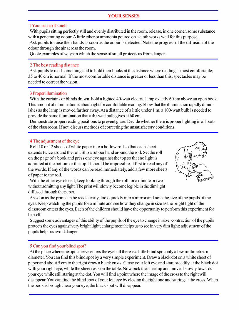
YOUR SENSES
1 Your sense of smell
With pupils sitting perfectly still and evenly distributed in the room, release, in one corner, some substance
with a penetrating odour. A little ether or ammonia poured on a cloth works well for this purpose.
Ask pupils to raise their hands as soon as the odour is detected. Note the progress of the diffusion of the
odour through the air across the room.
Quote examples of ways in which the sense of smell protects us from danger.
2 The best reading distance
Ask pupils to read something and to hold their books at the distance where reading is most comfortable;
35 to 40 cm is normal. If the most comfortable distance is greater or less than this, spectacles may be
needed to correct the vision.
3 Proper illumination
With the curtains or blinds drawn, hold a lighted 40-watt electric lamp exactly 60 cm above an open book.
This amount of illumination is about right for comfortable reading. Show that the illumination rapidly dimin-
ishes as the lamp is moved farther away. At a distance of a little under 1 m, a 100-watt bulb is needed to
provide the same illumination that a 40-watt bulb gives at 60 cm.
Demonstrate proper reading positions to prevent glare. Decide whether there is proper lighting in all parts
of the classroom. If not, discuss methods of correcting the unsatisfactory conditions.
5 Can you find your blind spot?
At the place where the optic nerve enters the eyeball there is a little blind spot only a few millimetres in
diameter. You can find this blind spot by a very simple experiment. Draw a black dot on a white sheet of
paper and about 5 cm to the right draw a black cross. Close your left eye and stare steadily at the black dot
with your right eye, while the sheet rests on the table. Now pick the sheet up and move it slowly towards
your eye while still staring at the dot. You will find a point where the image of the cross to the right will
disappear. You can find the blind spot of your left eye by closing the right one and staring at the cross. When
the book is brought near your eye, the black spot will disappear.
4 The adjustment of the eye
Roll 10 or 12 sheets of white paper into a hollow roll so that each sheet
extends twice around the roll. Slip a rubber band around the roll. Set the roll
on the page of a book and press one eye against the top so that no light is
admitted at the bottom or the top. It should be impossible at first to read any of
the words. If any of the words can be read immediately, add a few more sheets
of paper to the roll.
With the other eye closed, keep looking through the roll for a minute or two
without admitting any light. The print will slowly become legible in the dim light
diffused through the paper.
As soon as the print can be read clearly, look quickly into a mirror and note the size of the pupils of the
eyes. Keep watching the pupils for a minute and see how they change in size as the bright light of the
classroom enters the eyes. Each of the children should have the opportunity to perform this experiment for
himself.
Suggest some advantages of this ability of the pupils of the eye to change in size: contraction of the pupils
protects the eyes against very bright light; enlargement helps us to see in very dim light; adjustment of the
pupils helps us avoid danger.

6 Optical illusions
There are several very striking optical illusions in everyday life. When near the horizon, the sun and moon
appear to be much larger than when seen high in the heavens. When seen rising behind a hill, they seem to
move much more rapidly than they do when they are above us. Measurement of the sun’s or moon’s regular
diameter by an instrument or of their bearing when rising and setting does not confirm our first impressions.
Our estimates of sizes and distances near the horizon are inaccurate because we adopt comparatively near
terrestrial objects as our standard of comparison.
Make use of the theodolite or astrolabe and sextant made in Chapter VI, in measuring the speed of the sun
or the moon during its setting or rising. Compare its movement when it is above us.
Vision is not merely a static copy of the changing world. We have to learn to use our eyes as we have to
learn to use any other instrument. Our estimates of distance, direction and position do not merely depend on
what the retina of the eye (see experiment C 1 below) tells us. They involve complex movements of the
muscles that move the lens of the eye, of the muscles that change its curvature and of the muscles that move
the eye itself in its socket, together with the movements of the muscles of the neck and limbs and all the
signals which these muscles send to the brain when they move. We learn to co-ordinate our bodily move-
ments with those of our eye muscles and with the pattern of light on the retina from the common experience
of everyday life.
Part of our everyday experience is that light travels in straight lines. We learn to put things in line. The
delicate adjustment which makes us able to grasp a thing by seeing it, or to direct our gaze to the thing we
touch, is easily upset.
The following diagrams are of some well- know optical illusions. See that accurate measurements do not
confirm your impressions.
Nos. 1, 2, 3, 4. Look at lines a and b and compare their lengths.
No. 5. The black fence-posts appear to differ in height.
Nos. 6, 7. Look at the horizontal lines; are they parallel?
No. 8. Count the cubes and then carefully recount them.
No. 9. Look steadily at the staircase. Then turn your book slowly so that the staircase becomes inverted.
No. 10. The inside square appears to shift back and forth.
No. 11. Sometimes you appear to be looking at the top of the cube and sometimes at the bottom.
No. 12. Look at the figure and compare the distances ab and be.
No. 13. Glance at the figure; is it a true circle ?

7 Your sense of feeling
With a pencil mark off a 1 cm square on the back of the first joint of the middle
finger. Sharpen the pencil and press the point firmly against the skin at many
places within the square. Nerve endings that register sensations of touch, heat,
cold and pain are located in the skin. Find the points within the square that
produce each of these sensations. Quote examples of situations in which the
sensations of touch, heat, cold and pain might help us avoid harm or danger.
C. SOME ORGANS OF THE HUMAN BODY
I The eye
1 How to dissect an eye
A bull’s or a sheep’s eye can be used. Remove the clear
front skin or cornea. This will reveal the iris, and behind it
the crystalline lens.
This lens divides the eye into two parts, the front contain-
ing a thin liquid called ‘aqueous humour’ and the back a
jelly-like liquid, the ‘vitreous humour’.
Removing the lens and vitreous humour, the retina or
sensitive surface can be seen. It is more richly served with
sensitive cells at a spot opposite the lens called the yellow
spot. The nerves carrying the sensations pass out through a
hole in the outer sclerotic membrane; this spot is therefore
not sensitive to light and is called the blind spot.
2 How an image of an object appears on the retina
See Chapter XVI, experiment A 4, on the pinhole camera.
3 How the lens of the eye forms an image on the retina
See Chapter XVI, experiment C 11, on image formation by a convex lens.
Iris
Jelly like
fluid Scierotic Retina
PupilCornea Lens Blind
Spot
Optic
Nerve
II The heart
1 Making a simple device for listening to the heart beat
Make a stethoscope and have pupils use it to listen to the heart
action.
A very satisfactory demonstration stethoscope can be made
from a small funnel, a glass T-tube or Y-tube, and some rubber
tubing. Slip a piece of rubber tubing 7 or 8 cm long over the tip of
8 Testing your temperature sense
See Chapter XIII, experiment B 1.
T-Tube Rubber Tubing
Funnel
the funnel. (Any kind of small funnel will do, such as a glass laboratory funnel or the kind used to fill babies’
milk bottles.) Insert the T-tube into the other end of the short piece of rubber tubing and attach longer
pieces of tubing to both arms of the T-tube.
To use the stethoscope, have one pupil hold the funnel firmly over his heart while another holds the ends of
the long tubes in his ears. Heart sounds will be heard very clearly though of course, pupils will not be able to
interpret them. A doctor uses a stethoscope to find out if the heart action is normal.
This experiment will naturally lead to a discussion of what the heart does and its importance in maintaining
good health. Dangerous activities that might injure the heart and diseases that sometimes result in heart
impairment might also be discussed.

2 Taking the pulse rate
Demonstrate the proper method of taking the pulse rate by placing two fingers on the wrist and applying
slight pressure by pushing against the back of the wrist with the thumb. Practise finding the pulse rate by
counting for 15 and 30 seconds.
Rubber Tube & Clamp
Y- Tube
Bell Jar
Rubber Balloons
Sheet Rubber
3 The effect of exercise on the pulse
Have several pupils take their pulse rate at rest and after vigorous exercise. Summarize the results in a
table.
4 Watching the pulse beat of the heart
Stick a drawing pin into the end of a kitchen match. Hold your hand out with the inside of the wrist up and
level. Place the head of the drawing-pin on your wrist at the point where you can feel the heartbeat. Ob-
serve the match as it sways each time the heart beats.
III The lungs
2 What is your lung capacity?
Pupils may be interested in finding the volume of air that the lungs can displace. This can be determined
quite easily.
Fill a jar with water and fit a two-hole stopper. Insert a rubber tube through one hole; the other hole serves
as an outlet. Invert the jar in a larger vessel and have a pupil make one exhalation through the tube. Place
the fingers over the outlet and remove it from the large vessel. Use the graduate to measure the amount of
water needed to refill the jug. The amount of water needed will equal the volume of air that was exhaled.
1 How the lungs work
Demonstrate the action of the diaphragm by means of the apparatus
shown in the accompanying diagram. The rubber balloons re- present the
lungs, the tube represents the windpipe and the open bottom jar represents
the bony thoracic girdle. Lowering the diaphragm reduces the pressure
inside the chest cavity and air flows into the lungs. Raising the diaphragm
reverses the flow of air. Try moving the diaphragm with the clamp closed.
Rubber tube and clamp
“BE A GOOD SCIENTIST. FOLLOW INSTRUCTIONS EXTREMELY CAREFULLY.
WEAR PROTECTIVE CLOTHING WHEN WORKING ON ANY EXPERIMENTS
THAT INVOLVE FIRE OR EXPLOSIONS.”

CHAPTER XVIII
Some useful notes for teachers
1 Cleaning of glassware
Dissolve 100 g of potassium dichromate in a solution of 100 g of concentrated sulphuric acid in 1 litre of
water. Glassware can be soaked in the solution, which may be used over and over again.
Caution: Great care should be taken to avoid getting this very corrosive solution on skin or clothes. When
diluting concentrated sulphuric acid use a stone or earthenware vessel. Pour the acid very slowly into the
water as a great amount of heat is given out in the process.
The teacher should use his knowledge of chemistry to remove stains of know origin. If dirty vessels have
contained alkalis, or salts with alkaline reactions, then obviously the cleaning effect of a little dilute acid
should first be tried; if the stain is due to potassium permanganate, then the effect of sodium sulphite solution,
acidified with dilute sulphuric acid, should be tried, etc.
Alkalis slowly attack glass, and bottles which have contained caustic soda, etc., for a long time, will never
recover their original transparency.
2 Cleaning of mercury
When mercury, flowing over a surface, begins to leave ‘tails’, it should be
cleaned. It is allowed to drip into a tall cylinder containing nitric acid
slightly more dilute than the usual bench reagent. If the mercury falls through
the acid in a fine stream, as it does when made to pass through a capillary
tube attached to the end of a funnel, so much the better. The mercury is
then shaken up with water in a strong bottle to wash it free from acid.
Finally it is allowed to pass through a pinhole made in the middle of a
filter paper, which is folded in a funnel in the usual way. The last drops of
mercury remaining in the funnel should be kept for the next occasion when
mercury is cleaned. The mercury may be warmed in an air oven before the
final filtering, if required particularly dry.
3 Removal of air bubbles from, and the recovery of, spilt mercury
Air bubbles appear in a tube which is being filled with mercury. To
remove them the tube is closed with the finger, before it is quite full, and
inverted to allow a large air bubble to travel up it. As it moves upwards,
the large bubble collects the smaller ones. When the tube is turned up
again the large bubble reverses its track, moves upwards and escapes.
The small amount of mercury needed to fill the tube is then added.
Mercury spilt on tray, bench or floor, may be recovered by sucking it
into a small ‘wash- bottle’.
Funnel
Rubber Connection
Capillary Tube
Glass Cylinder
Dilute Nitric Acid
Air Drawn Out
Drop of Mercury
4 Collections of biological materials
These have little value unless they are kept in good condition, and the various kinds require different
treatment.

Flowers and plants: A collection of dried specimens is called a herbarium. Its main purpose is to provide
a supply of identified plants for general reference and to facilitate the naming of freshly collected specimens.
The teacher must always have at hand a supply of material with which to illustrate the various kinds of
flowers, leaves, fruit and roots. A specimen is not complete until all the parts of a plant are present. As
flowers and fruits do not always appear at the same time, it may be necessary to collect specimens of a
plant on more than one occasion.
Plants can be dried by pressing between sheets of newspaper. Special paper can be purchased for the
purpose, but newspaper makes a satisfactory substitute if two or three sheets are put on each side of the
specimen. A number of layers of specimens can be pressed at the same time. Drying is assisted by inserting
sheets of stiff corrugated paper between every few layers. The pressing can be carried out by putting the
sheets on a table under a heavily weighted drawing board. But drying is quicker between two wire frames
pressed together by spring fasteners, adjust- able screw fasteners, or straps. For the first few days the
specimens should be removed and placed between fresh dry paper every day, but as they become drier the
changes need be made less frequently.
Specimens are less subject to the growth of mould if brushed over gently with a solution of 0.5 g of
mercuric chloride in 100 mi of methylated spirit (methyl alcohol). The specimens should then be gummed,
or glued, to sheets of stiff drawing paper, or to cards (about 25 x 45 cm) specially made for the purpose.
The gum, or glue, should be made up with a little mercuric chloride, which also helps to repel insects.
Alternatively, or in addition, the specimen can be sewn to the card, or fastened to it with transparent adhe-
sive tape.
Each specimen should be labelled with at least: (a) the name and family of the species; (b) the name of the
person, or group, which has identified the specimen; (c) the place and date of finding; and (d) the name of
the finder.
Fruits or other bulky material associated with the specimen may have to be labelled and stored separately,
but small seeds can be put in an envelope and attached to the mounting card.
Insects: These are best killed in a wide mouthed bottle containing a suitable poison. A killing bottle is easily
made as follows. Some plaster of Paris is stirred to a thin paste with a 20 per cent solution of potassium
cyanide (the ‘commercial’ mixture of pot- assium and sodium cyanides is satisfactory) and quickly poured,
to a depth of about 1 cm, into the bottom of the bottle, where it soon sets hard. Cut a piece of blotting
paper to place over the cyanide and plaster of Paris. Punch the circle full of holes. The bottle should have a
screw-cap or a well-fitting airtight stopper, when it will remain effective for some months.
Caution: The cyanides of potassium and sodium are deadly poisonous and should be handled with the
utmost care.
A captured insect becomes merely insensitive when first put into a killing bottle; so it should be left for a
few hours until it is dead. It may then be removed to a setting board. A good substitute for the usual ‘board’
with a half-round groove consists of two sheets of compressed cork, or thick cardboard, with a gap be-
tween their edges, fixed on a third sheet, as shown in the figure. The setting board should be just large
enough to hold the insect satisfactorily. A long thin pin, of the ‘entomological’ type, is then pushed through
the middle of the insect’s thorax, securing it in position in the groove. The wings, legs and antennae are then
spread out carefully by means of seekers or fine tweezers, and kept in place by narrow strips of paper. (The
strips are held down by pins, which must not touch the insect.) The specimen must now be dried thor-
oughly—not always an easy matter, in the tropics, unless the setting board can be left in a desiccator for
some days. When it is dry the strips of paper are removed, as the various parts of the insect will now remain
in place. It tends to be brittle, so no attempt should be made to move the thorax pin. By means of this pin
the insect is lifted from the setting board and pinned in a suitable position on the mounting card. This is a
sheet of card- board or compressed cork previously cut to fit the bottom of a fiat tin or other suitable box,
the lid of which may be replaced by a glass top.

The preservation of specimens in the tropics is somewhat difficult, the chief problem being to prevent the
attack of various kinds of ants. Some useful notes for teachers Some minute species seem eager for viscera,
fresh or dried, and determined to remove everything except head, thorax and wings. The specimens must
be kept, therefore, either in ant-tight cases, or in cases on some support completely surrounded by liquid.
(Water requires frequent replacement owing to evaporation, and a layer of oil or disinfectant to prevent
mosquitoes from breeding. Used engine oil, from a car sump, needs less attention and is just as effective
as water.) Probably the best answer to the problem is to keep the insect boxes on a table with its legs
standing in tins of oil or disinfectant. The legs remain clean and dry if they stand on smaller tins inverted in
the middle of the liquid. Ants and other harmful insects are unable to cross the liquid surface.
Other biological specimens: Amphibians, reptiles, birds and mammals are killed with chloroform, a pad
of cotton wool, soaked in the liquid, being placed in the containing box. Mammals can be preserved in
either 70 per cent alcohol or 4 per cent formalin. Amphibians, reptiles, molluscs and crustaceans are most
suitably preserved in alcohol.
The cleaning of small skeletons, and the removal of viscera from large horny beetles, are jobs which, in the
tropics, can be left to ants. The dead creatures are exposed in a suitable place. Their presence is soon
detected by various ants, and before long a perfectly cleaned specimen remains. Bones can be scrubbed
with an old toothbrush; bleaching powder should first be applied, and then hydrogen peroxide.
5 Botanical specimens
To keep these fresh until there is time to press them, they may be put in a closed tin in a refrigerator, where
they readily remain stiff and fresh for a week.
6 Hand lens
Young pupils find difficulty in holding lens and object steady, and so
fail to keep the image in focus. Control is much easier if the thumb and
forefinger of one hand hold the object, and those of the other hand
hold the lens, and the tips of the middle fingers are pressed together.
7 Hydrogen balloons
In filling a toy balloon with hydrogen, the usual
thistle funnel can be replaced by a funnel fitted with
a tap. The delivery tube should be of as large a
diameter as possible. The end of the balloon tube
should be tied to the very end of the glass tube.
This allows the final tying-off of the balloon to be
done without first removing it from the glass tube.
The acid is run into the vessel and the tap closed.
The vessel should be a stout flask or bottle.
Balloon
Thread Tighly
BoundTap Funnel
Slack thread ready
to tie
Dilute Sulphuric Acid
and Zinc

8 Tropical conditions
There are many causes of trouble in a laboratory, especially during a wet season, in the tropics. Materials
perish, papers stick together, instruments rust, specimens go mouldy, lenses develop a fungus which quickly
renders them useless and ruins their accurately ground surfaces. In addition, ants, termites and other insects
continue their endless work of destruction.
Whatever can be kept in an air-tight container should be so kept. Glass jars, such as specimen jars with
lids well greased, are ideal. Screw-capped bottles, e.g. those which have contained sweets, are very useful.
Metal containers, such as biscuit tins, cake tins, etc., can be rendered fairly air-tight by strap- ping the joint
between the lid and container with insulating tape.
Lenses of microscopes should be kept in a desiccator when not in use. A piece of string soaked in creo-
sote and placed with the eyepiece in the lens container has been found useful for retarding the growth of
mould.
During the rainy season, microscopes, galvanometers and other sensitive instruments should if possible be
stored in an air-tight cupboard with a 50-watt electric bulb continuously burning. Needles can be inserted in
a piece of material in which some Vaseline has been rubbed. Metal instruments such as screw gauges,
vernier callipers, tuning forks, etc., should be greased. The screws of retort stand bases, rings and clamps
should be oiled frequently. Scalpels should be smeared with vaseline and kept in a case. The metal parts of
tools should be rubbed over with an oily rag.
Paste, gum and glue should contain some chemical to make them repellant to insects. Such adhesives are
sold specially prepared for the tropics. But, if the teacher makes his own, the addition of a very small
quantity of a solution of mercuric chloride, during the preparation, is generally effective. (Also, consult a
pamphlet on it’s Easy to Reduce Humidity, published by the Calcium Chloride Institute, 909 Ring Building,
Washington, D.C., U.S.A.)
9 Culture solution (for plants)
The following salts, of purest quality, should be dissolved together in 1 litre of distilled water :
0.70 g potassium nitrate
0.25 g calcium sulphate (hydrated)
0.25 g calcium hydrogen phosphate (hydrated)
0.25 g magnesium sulphate (hydrated)
0.08 g sodium chloride
0.005 g iron (ferric) chloride (hydrated)
To the solution should then be added:
1 ml 0.06 per cent boric acid solution 1 ml 0.04 per cent manganese chloride solution.
10 Stains
In general it is preferable to buy stains ready made up in solution, but the following are useful recipes:
(a) Aniline sulphate. A few drops of dilute sulphuric acid are added to a saturated solution.
(b) Borax carmine. 4 g of borax are dissolved in 100 ml of water; 3 g of carmine are added and the
solution warmed until the carmine is dissolved; 100 mi of 70 per cent ethyl alcohol are then added and the
solution filtered.
(c) Safranin. 1 g is dissolved in 100 ml of water or 100 mi of 50 per cent aqueous ethyl alcohol.
11 Sea water
A useful substitute for sea water can be obtained by dissolving the following in 2 litres of water:
45.0 g sodium chloride
3.5 g magnesium sulphate
5.0 g magnesium chloride
2.0 g potassium sulphate
12 Lime water
Lime is not very soluble in water, but the solution required for class use is easily made by adding 10 g of
slaked lime to 1000 cc distilled water. After shaking, allow it to settle before use.

13 Litmus solution
Litmus decomposes on heating; it should therefore be prepared by extracting the solid litmus with cold
distilled water. It should also be stored in bottles which allow access to air, otherwise the colour will
disappear.
14 Accumulator solutions
(a) Lead accumulator. The specific gravity of the sulphuric acid in various conditions of the battery is as
follows:
Fully charged 1.28
Half charged 1.21
Discharged 1.15
The above figures are approximate. The recommendations of the makers, usually printed on the battery,
should be followed. A rough guide to the making of a solution of sulphuric acid of specific gravity 1.28 is as
follows :
Concentrated sulphuric acid is added slowly, with stirring, to a beaker two-thirds full of distilled water, until
the solution is almost boiling. The solution is allowed to cool, and more acid is added, with similar precau-
tions, until the solution is again almost boiling. After cooling to room temperature, the specific gravity is
adjusted by the addition of more acid or more water, according to the hydro- meter reading.
(b) Nickel-iron (Nife) accumulator.
15 Pole finding paper
Blotting paper is soaked in a solution of sodium sulphate to which a few drops of phenolphthalein has been
added. Damp the paper before use, and apply the wires to it a short distance apart. The paper touched by
the negative pole becomes red.
16 Electroplating solutions 17 Silvering solution (for depositing a bright silver mirror on glass)
First, 12.5 g of silver nitrate are dissolved in 100 mi of water, and 32.5 g of sodium potassium tartrate are
dissolved separately in 100 mi of water. The two solutions are mixed, warmed to 550 C, and kept at that
temperature for 5 minutes. The mixture is then cooled and the clear liquid poured off from the precipitate
and made up to 200 ml for solution A. Second, 1.5 g of silver nitrate are dissolved in 12 ml of water. Dilute
ammonium hydroxide solution is added until the precipitate first formed is almost entirely redissolved. The
liquid is made up to 200 ml for solution B. The solutions A and B are then mixed. (The surface to be sil-
vered, having been cleaned very carefully to free it from all traces of grease, should be suspended upside
down in the solution, just below the surface. The solution can be put into a clean test-tube, or small flask,
and a mirror deposited on the inside of the vessel. The solution can be slightly warmed to hasten the deposi-
tion of the silver.)
18 Heat sensitive paper
A solution of cobalt chloride in water is added to a solution of ammonium chloride in water. (The propor-
tions do not matter.) The solution is diluted until it is pale pink. Filter paper soaked in the solution and
allowed to dry appears to be almost colourless, but on heating it will turn a bright green colour.

19 Cements for general purposes
Many special cements are now available on the market. Where they are not available the following can
easily be made up in the laboratory:
Acid-proof cement
1 part rubber solution
2 parts linseed oil
3 parts powdered pipeclay
Aquarium cement
(a) Equal parts of powdered sulphur, ammonium chloride, and iron filings are mixed. Boiled linseed oil is
then added and all are mixed thoroughly. White lead is added to form a thick paste. The cement should be
applied while fluid.
(b) Mix red lead with sufficient gold size to make a smooth paste and apply immediately. Allow a few
days to set and rinse the aquarium before using. Celluloid cement
Celluloid scraps can be dissolved in acetone or amyl acetate. This cement is useful when making up small
accumulators.
Cement for iron
90 parts fine iron filings
1 part flowers of sulphur
1 part ammonium chloride
Mix to a paste with water immediately before use.
Waxes
Chatterton’s compound
1 part Archangel pitch
1 part resin
Melt these together and add three parts of crepe rubber in small pieces.
Faraday’s cement
5 parts resin
1 part beeswax
1 part yellow ochre
Melt the resin and wax together in a tin and stir in the ochre.
Wood’s alloy (melting point 700 C)
2 parts lead
4 parts tin
8 parts bismuth
2 parts cadmium
Darcet’s alloy (melting point 700 C)
5 parts lead
3 parts tin
8 parts bismuth
20 Commercial adhesives
Many glues are now available for special purposes and it is worth selecting them carefully. China, glass and
metal can all be stuck by china cements. But if the mended articles are likely to be put into hot water the
only completely satisfactory results are from the new epoxy resins such as araldite. Paper and card can be
stuck with almost anything. Cleanest and easiest to use are the vegetable glues, such as Croid No.22;
Gripfix; Ste-fix; and Gloy. Textiles, leather and carpets are best stuck by the rubber lattice glues including
Copydex; Fabrex; and Jiffytex.
To stick plastics is very difficult, or even, as in the case of polythene, impossible. Best results are normally
obtained with a cement of the same base as the plastic, e.g. PVC sheeting with a PVC cement such as Pac
or Plastitex. The impact adhesives are very suitable for sticking laminated plastics to other materials.
Evostick and Formica Adhesive are rubber solutions, and can be removed from the hands by petrol. Most
other domestic adhesives yield to soap and water. There are many types of adhesive suitable for wood, of

which the following are good examples :
Hot animal glues: Cake Glue, Pearl Glue, Croid Aero.
Cold animal and fish glues: Croid Universal, Duroglue, Seccotine, Le Page’s Fish Glue.
Casein cold water glues: Casco, Croid Insol, Neverpart.
Urea Resins: Aerolite, Cascamite. PVA Emulsions: Casco PVA, Croid Polystic, Le Page’s Suregrip,
Unibond.
Animal glue and the emulsions are not resistant to cold water; resin glues are, and—for a time—to hot
water. Casein glues are less strong, have a fair resistance to heat and damp, but stain some woods. Sticking
things takes time. The more trouble taken in preparing and applying the glue the better the result
21 Insulating material for electrostatics experiments
Melt some paraffin wax in a can surrounded by a water bath. Add flowers of sulphur and stir until a pasty
mass is formed. This can then be moulded to fit the neck of a flask or cast into slabs as required.
22 Replacing eyepiece cross-wires
Drawn out glass tubing, monofilament nylon (obtained by unravelling a piece of nylon material) or spider
web can all be used for this purpose. Remove the supporting ring from the instrument. To make a frame for
holding the fibre, bend a U-piece of copper wire so that the arms are about 1 cm further apart than the
diameter of the ring. Place the arms under the fibre and stick it to them with a strong adhesive before
breaking off the ends. Now lift the frame and place the fibre in position over the supporting ring. Fix it down
with adhesive, and allow it to dry before trimming the ends.
If spider web is to be used, it is better to apply the adhesive to the frame before taking the filament from
the web, and to the supporting ring before placing it in position.
Satisfactory threads can also be made from Durofix, Centofix and Seccotine by making a blob on a piece
of paper and allowing it to dry partially. Very fine filaments of glue can then be drawn from the blob by
touching it with a pin or the nozzle of the tube. These can then be fitted as before, though with some practice
the operation can be carried out in the supporting ring, and the cross-wires fitted directly.
23 Soldering
Solder is an alloy of 66 per cent tin and 34 per cent lead which is used for making mechanical and electri-
cal joints between two metals. It is generally obtained in the form of rods or sticks. It is applied in the molten
state from a pointed block of copper known as a ‘bit’. This may be heated electrically (in which case a 75
watt heater is sufficient for general purposes) or it may be heated in a Bunsen flame.
Whatever method of heating is used, the surface of the bit must be cleaned by scraping or dipping in a
liquid flux, or the solder will not stick to it. When the right temperature has been reached, a little solder
applied from the stick will flow all over the bit. This process, a preliminary to the actual making of the joint,
is known as ‘tinning’.
The surfaces to be joined must also be cleaned and tinned. In this case the heat is supplied by holding the
hot copper bit on the object. When the solder begins to flow, it can be spread over the required area by
rubbing gently with the tip of the bit.
When both surfaces have been timed, they should be brought together and heat applied again by the bit
while they are held in the required position. The solder from the two surfaces runs together, and on cooling
makes a strong joint. Naturally large surfaces require more heat, and it may be necessary to use a flame to
bring the object to the required temperature.
The three essentials to successful soldering are cleanliness, flux and heat.
Fluxes Rosin is the most useful flux, especially for copper, brass, and tinplate, but it is not satisfactory for
iron and steel.
‘Dead’ zinc chloride or ‘killed spirits’ is the easiest flux to use, but it is corrosive, and it is best to avoid it
in electrical work. It is easily made by pouring hydrochloric acid on scraps of zinc and waiting until all
action has ceased. The liquid can then be filtered off into a wide-necked container.
There are many commercial fluxes for special purposes. Flwite is perhaps the best for all general purposes.
Soldering paste is now obtainable. A combination of solder and flux, it is applied with a brush and only
needs the heat of a soldering iron to make a satisfactory joint.

Tallow is used for joining lead to lead, or brass to lead, and rosin or killed spirits for joints in brass, copper,
tinplate, zinc; killed spirits are suitable for iron and silver. After soldering, killed spirits should be washed off
with water, and rosin or Flwite with methylated spirit.
24 Blackboard dressing
A satisfactory dressing can be made using:
100 g shellac
1000 ml alcohol
100 g powdered pumice
100 g crushed lamp black
The alcohol and shellac should be mixed first, as the shellac takes some time to dissolve. Some of the
alcohol should be set aside for mixing with the lamp black. This mixture should be added later through a
muslin strainer, and the whole should be well shaken before use.
25 ‘Dead black’
This is useful for painting the inside of ‘light’ apparatus, so that unwanted reflected light may be eliminated,
rays made less diffused, and images made sharper. Lamp black is mixed with gold size, and turpentine
added, with constant stirring, until the mixture is sufficiently thin for use as a paint.
26 Fluorescin solution (This is useful because the track of a ray of light travelling through a dilute solution of
fluorescin can be seen very clearly.) One gram of fluorescin is dissolved in 100 ml of industrial, or methylated,
spirit.
27 Cutting glass
(a) Sheet glass. First prepare a firm, hat surface on which to lay the glass: a table with a blanket or felt
thrown over it is satisfactory.
Using a rule and with a firm grip on the diamond or glass cutter, make a scratch along the required line. Turn
the sheet over and tap gently along the line of the scratch with the wooden end of the cutter. If this does not
result in a crack spreading along the line, turn the sheet over again and grasp it with one hand on each side of
the scratch and boldly bend it about, using this line as a hinge.
(b) Glass tubing. Tubing is best cut with a glass knife, and ‘everlasting’ knives are now available. A file,
though often used, makes a rounded valley in the glass instead of a crevice.
Make a scratch at the required point and holding between the thumb and finger each side of the cut, pull the
tubing apart, flexing slightly upwards.
To cut off a very short piece, hold in one hand and place the scratch over some ~m pivot such as a gas tap.
Strike the short end a smart blow with some hard object.
Wide tubing must be scratched all round to make a neat cut. A molten piece of glass rod placed carefully on
one part of the scratch will cause a crack to run round the circumference in each direction. If the two cracks
do not exactly join, the tube should be bent about the uncracked part as hinge in order to separate the two
pieces.
(c) To cut the bottom off a bottle. Make a scratch round the bottle at the required level. Wrap strips of
damp blotting paper on either side of this scratch. Play a fine gas flame on the cut, rotating slowly as the glass
begins to crack at this point.
If no gas flame is available the crack can be made in another way. See that the bottle is dry and well
corked. Then tie a length of very absorbent cotton around it horizontally, keeping the knot as flat as possible
and cutting off the loose ends. Level off carefully, so that the thread is exactly the same height up the bottle all
round. Turn the bottle on its side and soak the thread with kerosene from an eye-dropper. See that no
kerosene runs on the glass; if any does, wipe it off with cotton wool or filter paper. With the bottle still on its
side and resting on two wood blocks with a gap between them, set fire to the thread and rotate the bottle on
its axis with both hands until the whole thread is burning uniformly. Set the bottle upright on the table until the
thread is burnt out, at which stage the bottle may split in two of its own accord along the line of the burn. If

this does not happen as the flame goes out, gently lower the bottle upside down and vertically into cold
water. It must be kept absolutely vertical and must not be immersed beyond the line of the thread.
Smooth off the raw edge with a file, or by rubbing on a flat ground-glass plate on which has been smeared
a paste of carborundum powder.
(These bottles are useful for electrolysis experiments and as bell jars. In the latter case, a ring of soft
rubber can be used to make an air-tight seal.)
(d) For (a) and (c), if electricity, either AC or DC, is available, it is also possible to place a round of wire,
german silver or nichrome on the scratch. Switch on the current; the red hot wire will crack the glass along
the scratch. This method is also found useful in cutting used electric bulbs.
28 Extinguisher
Materials for putting out a fire must be kept handy in definite places. Teacher and pupils should know how
to use them quickly and correctly.
First-aid kit
A first-aid kit should be kept in each laboratory or adjoining preparation room, prefer- ably in a separate
cupboard. It must be kept in good condition, and the teacher must know how to use its contents.
29 Blueprinting
Solution I: potassium ferricyanide 10 g; water 50 mi.
Solution 2: ferric ammonium citrate 10 g; water 50 ml.
The solutions are prepared separately and kept in a dark room or in subdued light. For use, mix equal
quantities in subdued light and place in a shallow glass or enamelled tray. The paper is sensitized by brushing
the mixed solution over it with a soft, wide brush, or the paper may be placed on the surface of the solution
and allowed to float there for a few seconds. After sensitizing, the paper should be hung to dry in the dark
room.
An opaque object, a drawing in black ink on tracing paper or any material to be printed is placed and
fixed (on frame) on the paper. It should be exposed to sunlight (or artificial light) for several minutes and
then washed thoroughly in running water.
30 Shellac coating Dissolve 1 part of shellac in 5 parts of alcohol, and apply with a soft brush.
31 Preparation of common alloys
Lower melting alloys
These may, in general, be produced by using a bunsen burner as a source of heat. The bismuth and lead
are melted together, and then the other ingredients added. The temperature should not be higher than
necessary to prevent excess oxidation. The parts indicated are by weight.
Alloy Lead Tin Bismuth Cadmium
Wood’s metal 4 2 7 1
Solder 1 1 0 0
Electric fuse alloy 8.5 2.5 1.3 0
Higher melting alloys
These may be produced using a furnace. The copper should be melted first, and the other metals added to
it.
Alloy Copper Tin Zinc
Bronze 80 5 15

Brass, malleable 58 0 42
Brass, casting 72 4 24
32 Dyeing
(a) Direct. The dyeing of cotton should be preceded by removing the sizing from the fabric. This is ac-
complished by boiling it for 5 minutes in a dilute solution of HCI (hydrochloric acid). This solution is made
by adding 1 part of concentrated HCI to 10 parts of water. The following formula makes a satisfactory dye:
Congo red 0.5 g
NaHCO, (sodium bicarbonate) 2.0 g
Na2SO, (sodium sulphate) 1.0 g
H,O (distilled) 200.0 mi
The fabric should be boiled for 4 to 5 minutes and then rinsed in cold water and dried.
Instead of the congo red, methylene blue or primuline brown may be used. The dye and salts should be
mixed together ~st and then added slowly, with stirring, to the water. White silk, rayon or wool may be
dyed in the same way.
(b) Use of a mordant. Show the use of a mordant by heating a piece of white cotton fabric for 10 minutes
in a dilute solution of (NH,),SO, (ammonium sulphate). It should stand for a few minutes in dilute NH,OH
(ammonium hydroxide), after which it is rinsed. White silk may be mordanted by boiling for 5 minutes in a
tannic acid solution. It should then stand for a few minutes in a solution of tartar emetic. The effect of the
mordant may be studied by boiling the mordanted and unmordanted pieces of cotton and silk in alizarin
solution for a few minutes, after which they are rinsed and dried.
(c) Basic dyes. Show the use of basic dyes using malachite green. Boil samples of mordanted and
unmordanted cotton and mordanted and unmordanted silk in a solution of malachite green (or methylene
blue) for 5 minutes. They are then rinsed and dried. The malachite green solution is made by dis- solving 1 g
of dye in 200 g of water. Two hundred grams of water are acidified with acetic acid. Forty grams of the dye
solution are added to the acidified water.
(d) Ingrain or developed dyes. The development in the fibres of colours known as ingrain or developed
dyes requires the use of three solutions. The first consists of 0.1 g of primuline and O.lg of NaHCO, (so-
dium bicarbonate) dissolved in 100 mi of water. Boil a strip of unsized cotton in this solution for 1 minute,
then transfer it to the second solution. This solution is made by adding 0.5 g of NaNO, (sodium nitrite) and
3 mi of HCI to 100 mi of water. The strip is permitted to remain in this bath for 15 minutes and is then
transferred to the developing bath. The developing bath is made by dissolving 0.05 g of NaOH (sodium
hydroxide) and 0.05 g of phenol in 100 mi of water. Onstead of phenol, alpha naphthol or resorcinol may
be used.) The solution should be kept warm and the cloth allowed to remain in it for 20 minutes, after which
it is rinsed and dried. The results of various types of dyeing may be studied for quality.
33 Making matches
Make small splints of wood or use match- sticks from which the heads have been cut before they are
used. The ends of these sticks are dipped in melted paraffin wax. A mixture of 2 g of powdered KCIO,
(potassium chlorate) and 1 g of red Sb,S, (antimony trisulphide) is made. Do not grind. The two solids
should be mixed with the fingers. A thin mucilage is added to make a paste. The paraffined end of the
matchstick is dipped in this mixture, and it is hung head down to harden for a day. A surface for igniting the
matches is prepared by adding mucilage to equal volumes of red phosphorus and fine white sand. This is
spread on a cardboard or wooden surface and permitted to dry. The matches ignite when rubbed on this
surface.
The matches so prepared should be com- pared with commercially-made safety matches and with those
that are not of the safety variety.
34 Chemical ‘flower gardens’
Chemical ‘flower gardens’ are the result of osmotic action. A water glass (sodium silicate) solution of
specific gravity of 1.1 is desirable. Into 400 mi of this solution in a beaker are dropped pieces of the
sulphates of copper, iron, nickel and aluminium; the chlorides of copper and iron; and the nitrates of copper,
iron, cobalt, nickel and calcium. From these pieces the ‘flowers’ grow rapidly. The silicates form membra-
nous sacs which have a high concentration on the inside, thus promoting the rapid growth of the sac.

35 Winding a spiral spring
Phosphor bronze or steel wire (SWG 26) is suitable for an average spring. Choose a nail 15 cm long and
clamp the point in the jaws of a hand drill. Trap the end of the wire in the jaws also. Fix the drill horizontally
in a vice. Turn the handle of the drill, and pull hard on the free wire, using a piece of cloth or a leather glove
to protect your hand. When you have made the spring as long as you need, use a pair of pliers to bend the
free end round the nail, and cut the wire. The wire will uncoil a little, but this does not matter. Release the
wire from the jaws of the drill, cut off the ends of the spring so formed and remove the nail. Using pliers, grip
the two end turns of the spring together and bend them at right angles to form a loop. Repeat this at the
other end of the spring.
CHAPTER XIX
Some new tendencies in science teaching Science has been taught in schools for approximately a hundred
years. It began as natural philosophy, and by about fifty years ago had settled down to become a course of
scientific knowledge which was mainly factual and descriptive. During the last few years the science
programmes of many countries have been under scrutiny. The rapid progress of scientific knowledge during
this century has brought with it many new concepts, and a new unity of ideas. The manner as well as the
matter of science has changed: individual research has been replaced by team work; new techniques have
appeared, and the apparatus in use has become much more elaborate. The science taught in schools has
become divorced from everyday life, and many teachers have begun to feel that it is no longer sufficient to
teach the science of even a generation ago, but that matter should be included in the courses which is more
relevant to a modern age. There is nothing essentially new in this—sooner or later the skills and achieve-
ments of society have always been reflected in the curriculum of the schools. But the great advances that
have been made in science and mathematics, and in the associated technology, seem to have out- stripped
the progress of educational theory and practice.
For this reason, many countries are rethinking their educational programmes, and because physics is the
most advanced of the sciences, and possibly produces the most far- reaching effects on human life, it is this
subject which has received first consideration. The conclusions reached bear equally on the other science
subjects, but in what follows physics will be stressed because in this subject some complete syllabuses and
schemes have been worked out and tried as pilot schemes. In a short survey it is not possible to give in
detail the educational schemes of different countries, and in what follows the emphasis is on the principles
involved in the construction of the courses. Mention will be made of the work done by the Physical Sciences
Study Committee in the United States of America, by the Science Masters’ Association in the United
Kingdom, and by the International Union of Pure and Applied Physics, and a brief note is added on physics
teaching in the Union of Soviet Socialist Republics. The work of the Physical Sciences Study Committee
The Physical Sciences Study Committee is a group of university and secondary school physics teachers,
who undertook in 1956 the task of developing an improved physics course for American secondary
schools. Its work has been administered by Educational Services Incorporated, a non-profit making corpo-
ration. It has stimulated a general movement in the United States to improve secondary school science
education; similar groups are now working in the areas of biology, chemistry and mathematics.
A critical examination of school textbooks, apparatus, visual aids and library material revealed the following
deficiencies:
1 Textbooks in general reflected a scientific outlook which dated back half a century, and was no longer
representative of the views of the scientific community.
2 Genuine attempts to remain abreast of scientific developments had given even the best textbooks a
patchwork quality in which the unity of the subject had disappeared. The sheer mass of the material had
become unreasonably great.
3 With the increasing application of science to everyday life the books had become further overloaded by
more and more attention to technology.

4 The laboratory manuals suffered the same defects.
5 The potentialities of audio-visual aids were not being adequately exploited.
It was then decided to formulate a new physics course in which the unity of the subject would be pre-
served, and modern ideas would fall naturally into place. This has now been embodied in a textbook entitled
PSSC Physics. Naturally, this book is designed to fit the educational schemes of the United States, and in
fact is intended to be a one-year course for the last year of the secondary school. But the outline of the
syllabus, the ingenious Some new tendencies in science leaching experiments which have been incorporated
in the laboratory manual, and the supporting films and library books are of interest to teachers in all coun-
tries.
The syllabus divides naturally into four parts. The first is an introduction to time, space, matter and motion.
The second includes optics and waves. A particle model of light is developed to explain wave behaviour.
When the particle model is found inadequate, a kinematic picture of wave behaviour is introduced as an
alternative. In the third part, mechanics is presented through the dynamics of Galileo and Newton, leading to
a study of momentum, energy, and the conservation laws. The fourth part begins with an introduction to
electricity and magnetism, and the behaviour of particles in fields. Discovery of the photo- electric effect
leads back once more to a more subtle consideration of the nature of light. The synthesis of wave
behaviour and particle mechanics in a description of the atom bring the course to a conclusion.
In close relation to the ideas developed in the textbook, a laboratory programme was then conceived; in
this the following considerations were used as a guide:
1 Experiments should be true experiments, and not routine accumulation of data to agree with a result well
known in advance.
2 They should be performed with simple apparatus that can be quickly assembled by the student.
3 They should encourage further work along suggested lines, and should lead to the consideration of
theoretical ideas growing from the experiment, and be guided by those already mentioned in the textbook.
It was originally the intention of the committee to develop laboratory apparatus of a type which could be
constructed by the teachers and students themselves, but it was soon discovered that although there would
be obvious advantages in this, the burden on the teachers would be too great. The apparatus described in
the laboratory manual is now manufactured commercially to designs which have made it possible to set the
commercial price at a minimum.
Visual aids were then considered, and an examination of the many educational films available showed that
there were few which in manner and content furthered the ideas outlined in the textbook. Accordingly, a new
set of about sixty films was planned. The intention of these films is: (a) to ease the load on the teacher; (b) to
provide visual presentation of operations too difficult to carry out in the laboratory or to show by demon-
stration experiments; (c) to present a new subject, or to summarize and integrate a field of study; (d) to
show, where possible, real scientists at work in real situations, and speaking directly to the students.
A further activity of the committee has been the production of a set of paperback books about science and
scientists. Their primary purpose is to take the load off the textbook, leaving it free for the elucidation of
general principles. Sixty books are at present envisaged, which will provide a survey of physics within the
grasp of those following the main course. Some tell of the role of physics in the service of man, others are
biographical in nature and tell the stories of discoverers and their great discoveries. It is hoped, too, that
besides supplementing the course, they may be comprehensible to the layman, and perhaps help to bridge
the gap between the science and arts student.
Trials of the course outlined above showed that some teachers would find a guide to the textbook helpful.
The final effort of the committee was therefore to produce a set of teachers’ notes for this purpose, including
solutions to the problems in the text, and suggestions for teaching the subject. This comprehensive guide is
now available, and will prove invaluable to all attempting to adopt the course, or to adapt it to their own
special needs.
Further information
The Physical Science Study Committee is interested in rendering whatever services may be of use to those
individuals and schools who wish to know exactly what the new course is, and how it has come into being in
its present form. Such information, as well as advice on the present status of foreign translations and adapta-
tions, may be obtained from: Physical Science Study Committee, Educational Services Incorporated, 164
Main Street, Watertown 72, Mass.
The work of the Science Masters’ Association and the Association of Women Science Teachers in the
United Kingdom In 1957, motivated by the considerations mentioned earlier, the above associations issued a
policy statement on science teaching in schools. Subject panels later compiled syllabuses for the biological,
chemical and physical parts of the science course below the sixth forms, as well as for the specialist teaching
which follows.
The general recommendations were that science should be the ‘core’ subject in gram- mar schools in much
the same way for example as English and mathematics are at present, and as classics used to be. Believing
that all students should study science up to the fifth form years, and that all specialists should study some
science, the authors of the statement laid down the following principles. Teaching should be divided into three
phases: an introductory phase covering the first two years, an intermediate phase up to about sixteen years of
age, and an advanced phase to include some specialization.
In 1960 the committee issued syllabuses for physics, chemistry and biology covering these three phases. To
make it possible to include material more closely connected with modern life, difficult concepts, ideas and
numerical problems on energy, magnetism, and certain aspects of heat and light were omitted from the early
and intermediate phases of the physics course. The criterion for the inclusion of any item at the advanced
phase was, ‘Is it fundamental to physics today?’ Subjects more properly included under the heading of
applied physics or technology have also been excluded. These have been replaced by substantive sections on
mechanics, the under- standing of which is so essential and fundamental to an appreciation of modern phys-
ics.
The same general principles have been applied to chemistry. Although it can be claimed that the teaching of
chemistry in British schools has at its best been as good as any in the world, some modifications are neces-
sary to meet the new situation. The past syllabuses have been too heavily weighted with facts, preparation,
and details of procedure.
The general plan of the early stages in chemistry, it is suggested, should be visualized as a series of empirical
investigations, with the emphasis on experimentation and observation. Speculations in the light of ascertained
facts will then arise, and opportunities will be provided for the invention of simple theories. These in turn will
lead to new theories and the discovery of new facts. In the second phase, it is suggested that the pupil should
learn to appreciate the nature of scientific laws, the inter-relationship between facts and theories, and the
intimate relation between matter and electricity. Some ideas, too, should be formed concerning the need to
assume a particle structure of atoms when considering the reactions in which matter takes part, as well as the
factors which can affect chemical reactions in general. On the sound basis of the first two phases of teaching,
it should now be possible to discuss the material basis of chemistry, types of materials and changes, and their
full explanation in terms of molecules and ions.
The committee, reviewing the teaching of biology, emphasized that this term implies not a single science, but
a whole group of sciences. It was further realized that biology can be used to unite all the sciences, and to
link them with psychology, the social sciences, and with history and the arts. To achieve this linking effect,
biology should be centred on the study of whole organisms, and not on anatomical, physiological, cytologi-
cal or biochemical abstractions.
In the introductory and intermediate phases biology should be part of an introduction to science as a whole.
Personal observations on Some new tendencies in science reaching live organisms should be made, and
prominence given to practical work. The organisms studied should be selected from easily available local
flora and fauna, and simple habitat studies are eminently suitable. Nutrition and respiration can be studied as
parts of wider science topics with physical, chemical and biological aspects. At the intermediate phase an
advance should be made in greater depth and on a narrower front than at the introductory phase. A further
suggestion was that a syllabus based on that of the level of the Cambridge Local Examinations Syndicate
meets the above requirements, and contains more useful suggestions to teachers than many of the other

syllabuses. The syllabus at the advanced stage grows out of that of the earlier phases. Sixth formers ap-
proach the subject with more mature minds: more advanced practical work is possible. Individual dissec-
tions of animals can take the place of the previous demonstrations. The staining and mounting of some
microscopical preparations can also be undertaken. Teachers can develop particular sections according to
their own outlook and interests, and to the local conditions, especially as regards field work. The syllabus
would therefore include further study of the mammal and of flowering plants; a variety of patterns of life;
elementary ecology, and a number of general biological topics under the general title of ‘The nature, continu-
ance and diversification of life’.
The work of all these planning committees is not complete, but the suggestions outlined have been embod-
ied in detailed syllabuses published by the associations. The great freedom allowed to British teachers
allows them to be interpreted in many different ways. Pilot schemes are in operation in the schools, and in
the next few years much will be learnt of how best to achieve the desired objectives.
Publications
The following publications of the Science Masters’ Association and the Association of Women Science
Teachers are obtainable at 2s. each from the Librarian, Science Masters’ Association, 52 Bateman Street,
Cambridge: A policy statement on science education.
Physics for grammar schools.
Chemistry for grammar schools.
Biology for grammar schools.
The work of the International Union of Pure and Applied Physics
In July 1960 an international conference on physics teaching took place in Paris. It was sponsored by the
Organization for European Economic Go-operation (now OECD), Unesco and the International Union of
Pure and Applied Physics, and was part of a wider study of the teaching of science, mathematics and
chemistry being undertaken by OEEC. Delegates from the Netherlands, Switzerland, Italy, Denmark,
France, the United States of America, Japan, Poland, Germany and the United Kingdom considered topics
including examinations, laboratory work, the training of teachers, and the use of films and television in
science teaching. They further considered the defects of the present systems, the approach to the teaching of
physics and the supply of physics teachers.
The diversity of conditions and facilities in the various countries made it very difficult to arrive at general
conclusions. Some countries were inevitably criticised for over-emphasizing the theoretical aspects of the
subject, and others for the inclusion of too much practical work. But all were agreed that drastic changes in
the method and content of physics teaching were necessary. General agreement was however found in an
agreed syllabus, and suggestions were made for its implementation. These are to be found in a full report of
the conference. This is now published under the title International Education in Physics, John Wiley and
Sons Inc., 440 Park Avenue S., New York 16, N.Y. Science teaching in the Union of Soviet Socialist
Republics
The revision of the science teaching programme in the Soviet Union began as early as 1919, when a State
Council was set up to provide, amongst other things, general and methodological guidance and curricula for
the higher schools. In 1921 a further special commission declared the aim of the Soviet high schools, and set
up schemes for the training of scientists and teachers.
But the greatest step forward was made in 1957, when the regulations of the Ministry of Education re-
quired all scientists in post- graduate training to study pedagogics, psychology, logic, and methods of
teaching special subjects, as well as the skill of conducting classes. This resulted in a great increase in the
numbers of scientists available for teaching.
The Academy of Pedagogical Science set up in 1943 has rendered great help to the teachers. It provides
information on new teaching methods, and promotes constructive co-operation between teachers and
educational Some new tendencies in science leaching authorities, and furthers the production of textbooks.
It is also responsible for the syllabuses and supply of apparatus, as well as for the textbooks to be used. The

syllabus thus includes a full list of the demonstration experiments to be shown, the topics to be discussed,
the films to be shown, and the expeditions and factory visits to be made. Regional training institutes set up in
all areas supplement the work in the academy by organizing courses, lectures and seminars.
Education is now compulsory from 7 to 18 years of age, and all pupils have the same basic course for the
first eight years. The schools are co-educational, and classes must not exceed 30 in number, though more
usually they do not exceed 24. There is no ‘streaming’; all pupils go through this same basic course. For the
last three years the pupils proceed to a type of school suited to their abilities.
Biology is the first science to be taught, but in the last three years gives way to physics. The syllabus here
includes advanced work on atomic structure; nuclear energy; isotopes; the physics of light; supersonics; the
photo- electric effect, semi-conductors, as well as work on three-phase alternating current. There is a
great emphasis on practical work by the students, and also on good demonstration experiments. Most
schools possess an oscilloscope and the necessary apparatus for teaching alternating current. As mentioned,
the apparatus is supplied by the academy, and is thus of a type most suitable for the purpose.
The syllabus outlined is only a minimum; sufficient time is allowed for individual teachers to follow their
own ideas. The intention of the syllabus, the suggestions and the provision of apparatus is merely to ensure
that all pupils are adequately taught, even by the less gifted teachers.
This brief outline shows what consistent effort, immense energy and resources have been directed towards
science teaching during the last 40 years. The result is seen in the outstanding position of Soviet science
today. References
The training of scientists in the Soviet Union, by G. Galkin. Education in the USSR, by M. I. Kondakov.
end of book