Embed Size (px)
Citation preview
Page 1 of 22Catalog #70403Brochure No. 63-0147
©2003 Edelbrock CorporationRev. 1/03
1999-2003 FORD F-150 LIGHTNING PERFORMER EFI SERIES NITROUS SYSTEM
Catalog Part #70403
Table of ContentsPage #
a. General Warranty . . . . . . . . . . . . . . . . . . . . . . . . . . . . . . . . . . . . . . . . . . . . . . . . . . . . . . . . . . . . . . . . . . . 2
b. Before You Install Your Edelbrock Nitrous System . . . . . . . . . . . . . . . . . . . . . . . . . . . . . . . . . . . . . . . . . . . . 3
c. What is Nitrous Oxide? . . . . . . . . . . . . . . . . . . . . . . . . . . . . . . . . . . . . . . . . . . . . . . . . . . . . . . . . . . . . . . . 4
d. Safety Tips for Working with Nitrous Oxide . . . . . . . . . . . . . . . . . . . . . . . . . . . . . . . . . . . . . . . . . . . . . . . . . 4
1.0 Introduction to the Edelbrock Nitrous Systems Kit1.1 General Information. . . . . . . . . . . . . . . . . . . . . . . . . . . . . . . . . . . . . . . . . . . . . . . . . . . . . . . . . . . . . . . . . . 5
1.2 Jet Map Information . . . . . . . . . . . . . . . . . . . . . . . . . . . . . . . . . . . . . . . . . . . . . . . . . . . . . . . . . . . . . . . . . 6
1.3 Engine Operation Considerations . . . . . . . . . . . . . . . . . . . . . . . . . . . . . . . . . . . . . . . . . . . . . . . . . . . . . . . . 6
1.4 1999-2003 Ford F-150 Lightning Performer EFI Series Kit Contents. . . . . . . . . . . . . . . . . . . . . . . . . . . . . . . 7
2.0 Performer EFI Series Nitrous System Installation2.1 Nitrous Bottle Mounting. . . . . . . . . . . . . . . . . . . . . . . . . . . . . . . . . . . . . . . . . . . . . . . . . . . . . . . . . . . . . . . 8
2.2 Nitrous Bottle Mounting Instructions . . . . . . . . . . . . . . . . . . . . . . . . . . . . . . . . . . . . . . . . . . . . . . . . . . . . . 9
2.3 Nitrous Bottle Orientation . . . . . . . . . . . . . . . . . . . . . . . . . . . . . . . . . . . . . . . . . . . . . . . . . . . . . . . . . . . . . 9
2.4 Nitrous Bottle Installation. . . . . . . . . . . . . . . . . . . . . . . . . . . . . . . . . . . . . . . . . . . . . . . . . . . . . . . . . . . . . 10
2.5 Nitrous Feed Line Mounting. . . . . . . . . . . . . . . . . . . . . . . . . . . . . . . . . . . . . . . . . . . . . . . . . . . . . . . . . . . 11
2.6 Solenoid Mounting . . . . . . . . . . . . . . . . . . . . . . . . . . . . . . . . . . . . . . . . . . . . . . . . . . . . . . . . . . . . . . . . . 11
2.7 Nitrous Spray Nozzle Installation . . . . . . . . . . . . . . . . . . . . . . . . . . . . . . . . . . . . . . . . . . . . . . . . . . . . . . . 12
2.8 EFI Vacuum “Tee” Installation . . . . . . . . . . . . . . . . . . . . . . . . . . . . . . . . . . . . . . . . . . . . . . . . . . . . . . . . . 13
2.9 Fuel Pressure Safety Switch Installation . . . . . . . . . . . . . . . . . . . . . . . . . . . . . . . . . . . . . . . . . . . . . . . . . . 13
3.0 Electrical System Installation3.1 Nitrous Electrical Kit Contents . . . . . . . . . . . . . . . . . . . . . . . . . . . . . . . . . . . . . . . . . . . . . . . . . . . . . . . . . 14
3.2 Nomenclature Descriptions . . . . . . . . . . . . . . . . . . . . . . . . . . . . . . . . . . . . . . . . . . . . . . . . . . . . . . . . . . . 14
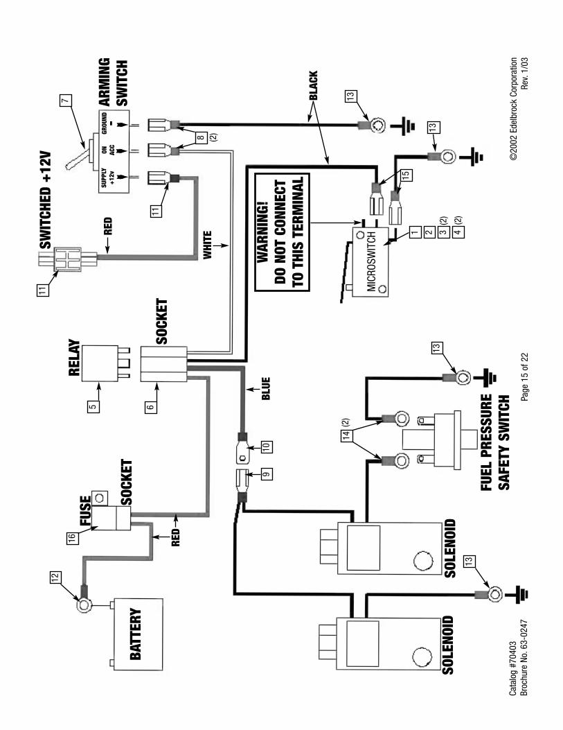
3.3 Nitrous Electrical System Wiring Diagram . . . . . . . . . . . . . . . . . . . . . . . . . . . . . . . . . . . . . . . . . . . . . . . . 15
3.4 Nitrous Electrical System Installation Procedures . . . . . . . . . . . . . . . . . . . . . . . . . . . . . . . . . . . . . . . . . . . 16
3.5 Nitrous Relay and Fuse Holder Installation . . . . . . . . . . . . . . . . . . . . . . . . . . . . . . . . . . . . . . . . . . . . . . . . 16
3.6 Arming Switch and Installation . . . . . . . . . . . . . . . . . . . . . . . . . . . . . . . . . . . . . . . . . . . . . . . . . . . . . . . . 17
3.7 Microswitch Installation and Wiring . . . . . . . . . . . . . . . . . . . . . . . . . . . . . . . . . . . . . . . . . . . . . . . . . . 17-18
3.8 Final Electrical Installation Recommendations . . . . . . . . . . . . . . . . . . . . . . . . . . . . . . . . . . . . . . . . . . . . . 18
4.0 Before You Run Your Edelbrock Nitrous System4.1 Fuel System Check . . . . . . . . . . . . . . . . . . . . . . . . . . . . . . . . . . . . . . . . . . . . . . . . . . . . . . . . . . . . . . . . . 194.2 Nitrous System Check. . . . . . . . . . . . . . . . . . . . . . . . . . . . . . . . . . . . . . . . . . . . . . . . . . . . . . . . . . . . . . . 19
5.0 Solenoid Inspection and Maintenance. . . . . . . . . . . . . . . . . . . . . . . . . . . . . . . . . . . . . . . . . . . . . . . . . . . . . . 19
6.0 Troubleshooting and Routine Maintenance . . . . . . . . . . . . . . . . . . . . . . . . . . . . . . . . . . . . . . . . . . . . . . . 20-22
Page 2 of 22Catalog #70403Brochure No. 63-0147
©2003 Edelbrock CorporationRev. 1/03
Thank You….…for purchasing an Edelbrock Nitrous Oxide Injection System.
Nitrous Oxide injection is one of the most exciting performance enhancements, for the dollar invested, on the market today. With theuse of nitrous oxide come some important safety considerations. This manual has been written to help you during the installationand use of your Edelbrock Nitrous System. Please read it completely before you install and use your system. Please pay closeattention to the safety information at the beginning of each section. The information contained there specifically pertains to each ofthe components and installation methodologies within the section.
Please take the time to read and understand the following….
By installing your Edelbrock Nitrous System, you indicate you have read this document and you agree with the terms stated below:
It is the responsibility of the purchaser to follow all installation instruction guidelines and safety procedures supplied with theEdelbrock Nitrous Systems. It is also the responsibility of the purchaser to determine the compatibility of the product with the vehicleor the device on which the purchaser intends to install it.
Edelbrock Corporation assumes no responsibility for damages occurring from misuse, abuse, improper installation, improperoperation, lack of responsible care, or all previously-stated reasons resulting from incompatibility with other manufacturer’s productsand/or systems.
Edelbrock Corporation neither recommends nor condones the use of products manufactured or sold by Edelbrock Corporation for useon vehicles, which may be driven on public roads or highways, and assumes no responsibility for damages incurred by such use.
Edelbrock Corporation assumes no responsibility for damages incurred by the use of products manufactured or sold by EdelbrockCorporation on vehicles used for competition or racing.
Edelbrock General Warranty
It is the constant endeavor of Edelbrock Corporation to give our customers the highest quality products obtainable. Edelbrock warrantseach new product, except Performer Series Carburetors, Race Division Parts, Tubular Exhaust Systems, RPM Series Mufflers, Cat-Back Systems and Performer IAS Shock Absorbers which are warranted separately, to be free from defects in both workmanship andmaterial for a period of one (1) year from the date of purchase, provided that the product is properly installed, subjected to normaluse and service and that the product is not modified or changed in any way, negligence by customer or installer or used for racingor competition purposes.
Our warranty service and repair facility is located at 2700 California Street, Torrance, California 90503. Customers who believe theyhave a defective product should either return it to the dealer from which it was purchased or ship it directly to Edelbrock along withproof of purchase and a complete description of the problem. The product must be returned freight pre-paid. If a thorough inspectionof the product by the factory indicates defects in workmanship or material, our sole obligation shall be to repair or replace the product.Warranty covers only the product itself and not the cost of installation or removal.
Edelbrock Corporation shall not be liable for any and all consequential damages occasioned by the breach of anywritten or implied warranty pertaining to this sale in excess of the purchase price of the product sold.
If you have any questions regarding a product or installation, please contact our Technical Department, toll free at 1-800-416-8628 from 7:00am to 5:00pm PST, Monday through Friday.
Thank you again for choosing Edelbrock Nitrous Systems.
Page 3 of 22Catalog #70403Brochure No. 63-0147
©2003 Edelbrock CorporationRev. 1/03
Caution!!
Before You Install Your Edelbrock Nitrous System…
Please read this Installation manual fully before installing this system.
You will need to have available the following tools:
Hand Tools
❑ Socket set including ratchets and extensions
❑ Screwdrivers
❑ Pliers
❑ Bench vise
❑ Wire crimping pliers, wire strippers
❑ Floor jack
❑ Vehicle jackstands
❑ Safety glasses
Power Tools
❑ Power drill
❑ Drill bits (1/4”, 1/2” and 3/8”)
You should understand the following skills:
❑ Power tool safety procedures
❑ Undercar safety procedures
❑ Proper measuring techniques
❑ Proper electrical assembly techniques
❑ Basic engine operation and tuning
Anytime you have questions or concerns with your Edelbrock Nitrous System, please call our Technical Support Hotline at 1-800-416-8628
before you start your engine.℡
Page 4 of 22Catalog #70403Brochure No. 63-0147
©2003 Edelbrock CorporationRev. 1/03
WHAT IS NITROUS OXIDE?
Nitrous Oxide is a cryogenic gas composed of nitrogen and oxygen molecules. It is stored as a “gas over a liquid” which means thatboth liquid and gaseous nitrous oxide is delivered into your engine. It is 36% oxygen by weight, which is what produces the addedhorsepower. By injecting more oxygen (and a corresponding fuel signal), we create the additional power much like a superchargeror a turbocharger does.
Nitrous Oxide is considered an “oxidizer” and not a fuel. Nitrous oxide is non-flammable by itself. Because nitrous oxide is acryogenic, the same safety methods in handling dry ice apply to nitrous. Direct contact with the skin will cause a burn similar tocontact with dry ice. The exception in using nitrous oxide comes from increased breathing hazards associated with the gaseousproperties of nitrous oxide.
Nitrous Oxide is offered for sale in two common grades, which are U.S.P., and Nytrous Plus. U.S.P. nitrous oxide is medical gradenitrous oxide. Its common use is dental and veterinary anesthesia as well as use as a propellant in food such as canned whip cream.U.S.P. is not available to the public and would provide no advantage in the making of horsepower over the automotive grade nitrousoxide.
Nytrous Plus was specifically designed for automotive consumption and differs from U.S.P. in that it contains trace amounts of sulfurdioxide (100 parts per million or “PPM”) added to prevent substance abuse. The Sulfur Dioxide is an irritant to all of your breathingpassageways and will cause sore throats and sore nasal passages. Nytrous Plus was specifically created for automotive applicationsand is available for sale to the public at many speed shops across the USA.
Safety Steps For Working With Nitrous Oxide
1. Never inhale Nytrous Plus (Nitrous oxide (N2O) for vehicular use) as continued exposure can cause death. Nytrous Plus has
a maximum of 100 parts per million (ppm) of sulfur dioxide and will cause irritation to nose and throat passageways.2. When working around any high-pressure gas including nitrous oxide, take all precautions to ensure that exposure to nitrous
oxide is minimized.3. Do not vent nitrous oxide to atmosphere in confined spaces. Only vent nitrous oxide in well-ventilated and open areas.4. Liquid nitrous oxide can cause burns to human flesh so protect all skin in and around your hands, arms and face. Wear
safety glasses and rubber gloves to protect from liquid nitrous oxide splatter.5. When venting down the nitrous system, vent the line down closest to the nitrous bottle.6. Do not use any form of Teflon tape as sealant on fitting connections. Use only Teflon paste.7. When washing components, ensure the clean components are completely dry, free of oils, and solvents. Failure to remove
all liquids could cause component or system failure.8. Always turn the bottle off before making any repairs to the nitrous delivery system.9. To safely release nitrous oxide in a pressurized line:
a. Position vehicle in a well-ventilated, unconfined space.b. Turn bottle off.c. Slowly loosen the nitrous feed line at the bottle until you hear a light hissing noise.d. Allow the entire nitrous pressure to vent from the line.e. Perform your work on the system.f. Tighten the nitrous line to the bottle.g. Slowly open the nitrous bottle valve, listening for leaks.h. Perform leak checks on all affected fittings and the bottle fitting.
Page 5 of 22Catalog #70403Brochure No. 63-0147
©2003 Edelbrock CorporationRev. 1/03
1.0 Introduction to your Edelbrock 1999-2003 Ford Lightning Performer EFI Nitrous System
Within the pages of this manual is information, safety tips and operation instructions for your new Edelbrock Nitrous System.Watch for these symbols to know where to go for information.
….There is safety related information here.
...shows where technical information about your vehicle or specific skills that may help duringinstallation.
….call Edelbrock Technical support hotline for more information.
1.1 General Information
The Edelbrock Performer EFI Nitrous System (Part Number 70403) is designed for the 1999 to 2003 FordLightning SVT with stock or slightly modified engines. Horsepower and torque increases can vary withequipment upgrades and modifications.
This system utilizes one nozzle that is installed in the intake boot just before the throttle body and after the air filterunit. The additional fuel needed is supplied by the vehicle’s standard fuel system.
This system has been designed with some flexibility as to where certain components can be located to allow easyinstallation on vehicles with upgraded or modified equipment. The solenoid and microswitch brackets are designedto be manipulated (bent, cut, twisted, etc.) and the electrical components have properly-sized and ample lengths ofwire.
This system includes the bottle (shipped empty), bottle feed line and universal footprint steel bottle brackets. Themounting brackets also include rubber insulators to protect the surface of your nitrous bottle while mounted in thebrackets. When installing your nitrous bottle, pay close attention to the installation instructions for the location ofyour bottle. Make sure that the installation of your bottle does not interfere with any systems that may lie under thelocation where you plan to drill holes for mounting the brackets.
Call your local automotive store, motorcycle shop or race track for refilling of your bottle. Trust a professional toproperly fill your bottle and reference your installation manual when re-installing your filled bottle back into yourvehicle.
Always take care when handling a full bottle of nitrous oxide. Please reference this manual for further safetymeasures to take during the handling of a nitrous oxide bottle.
Please follow all safety methods during the installation of your Edelbrock Nitrous System, and follow all vehicleregulations and road laws when using your nitrous system.
℡
Page 6 of 22Catalog #70403Brochure No. 63-0147
©2003 Edelbrock CorporationRev. 1/03
1.2 Jet Map Information
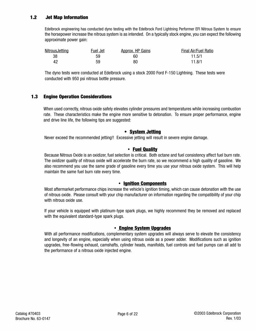
Edelbrock engineering has conducted dyno testing with the Edelbrock Ford Lightning Performer EFI Nitrous System to ensurethe horsepower increase the nitrous system is as intended. On a typically stock engine, you can expect the followingapproximate power gain:
NitrousJetting Fuel Jet Approx. HP Gains Final Air/Fuel Ratio38 59 60 11.5/142 59 80 11.8/1
The dyno tests were conducted at Edelbrock using a stock 2000 Ford F-150 Lightning. These tests wereconducted with 950 psi nitrous bottle pressure.
1.3 Engine Operation Considerations
When used correctly, nitrous oxide safely elevates cylinder pressures and temperatures while increasing combustionrate. These characteristics make the engine more sensitive to detonation. To ensure proper performance, engineand drive line life, the following tips are suggested:
• System JettingNever exceed the recommended jetting!! Excessive jetting will result in severe engine damage.
• Fuel QualityBecause Nitrous Oxide is an oxidizer, fuel selection is critical. Both octane and fuel consistency affect fuel burn rate.The oxidizer quality of nitrous oxide will accelerate the burn rate, so we recommend a high quality of gasoline. Wealso recommend you use the same grade of gasoline every time you use your nitrous oxide system. This will helpmaintain the same fuel burn rate every time.
• Ignition ComponentsMost aftermarket performance chips increase the vehicle’s ignition timing, which can cause detonation with the useof nitrous oxide. Please consult with your chip manufacturer on information regarding the compatibility of your chipwith nitrous oxide use.
If your vehicle is equipped with platinum-type spark plugs, we highly recommend they be removed and replacedwith the equivalent standard-type spark plugs.
• Engine System UpgradesWith all performance modifications, complementary system upgrades will always serve to elevate the consistencyand longevity of an engine, especially when using nitrous oxide as a power adder. Modifications such as ignitionupgrades, free-flowing exhaust, camshafts, cylinder heads, manifolds, fuel controls and fuel pumps can all add tothe performance of a nitrous oxide injected engine.
Page 7 of 22Catalog #70403Brochure No. 63-0147
©2003 Edelbrock CorporationRev. 1/03
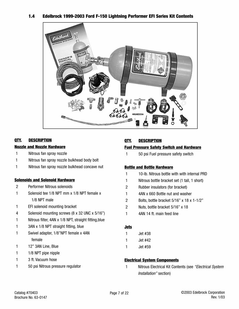
1.4 Edelbrock 1999-2003 Ford F-150 Lightning Performer EFI Series Kit Contents
QTY. DESCRIPTION
Nozzle and Nozzle Hardware
1 Nitrous fan spray nozzle
1 Nitrous fan spray nozzle bulkhead body bolt
1 Nitrous fan spray nozzle bulkhead concave nut
Solenoids and Solenoid Hardware
2 Performer Nitrous solenoids
1 Solenoid tee 1/8 NPT mm x 1/8 NPT female x
1/8 NPT male
1 EFI solenoid mounting bracket
4 Solenoid mounting screws (8 x 32 UNC x 5/16”)
1 Nitrous filter, 4AN x 1/8 NPT, straight fitting,blue
1 3AN x 1/8 NPT straight fitting, blue
1 Swivel adapter, 1/8”NPT female x 4AN
female
1 12” 3AN Line, Blue
1 1/8 NPT pipe nipple
1 3 ft. Vacuum hose
1 50 psi Nitrous pressure regulator
QTY. DESCRIPTION
Fuel Pressure Safety Switch and Hardware
1 50 psi Fuel pressure safety switch
Bottle and Bottle Hardware
1 10-lb. Nitrous bottle with with internal PRD
1 Nitrous bottle bracket set (1 tall, 1 short)
2 Rubber insulators (for bracket)
1 4AN x 660 Bottle nut and washer
2 Bolts, bottle bracket 5/16” x 18 x 1-1/2”
2 Nuts, bottle bracket 5/16” x 18
1 4AN 14 ft. main feed line
Jets
1 Jet #38
1 Jet #42
1 Jet #59
Electrical System Components
1 Nitrous Electrical Kit Contents (see “Electrical System
Installation” section)
Page 8 of 22Catalog #70403Brochure No. 63-0147
©2003 Edelbrock CorporationRev. 1/03
2.0 Performer EFI System Installation
2.1 Nitrous Bottle Mounting
The nitrous oxide storage cylinder is typically called a “nitrous bottle”. It is an aluminum cylinder, designed andmanufactured to withstand very high pressures. The valve on top of the bottle is a high-flow design that allowseasy opening and closing which controls the nitrous flow to the engine compartment.
Accurate calibration of your nitrous system depends on the bottle remaining at a stable temperature. In vehicles(such as Corvettes) where the bottle must be mounted in an area subject to direct sunlight, it is suggested that thebottle be shielded with a bottle blanket.
If the bottle is mounted inside the passenger compartment or in a space that has access to the passengercompartment such as hatchbacks or vehicles that feature fold down rear seats, the pressure relief device (PRDvalve) must be vented externally from the cockpit. This procedure will prevent the passenger compartment fromfilling with a cloud of nitrous oxide, should the safety pressure relief valve rupture. For more information, pleasecontact the tech line.
Special consideration should be made to protect the bottle installation by not placing the bottle in aknown crumple or crash zone within the vehicle. At no time should the bottle be mounted within theseating area of the passenger compartment of a street-driven vehicle.
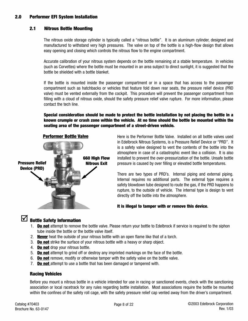
Here is the Performer Bottle Valve. Installed on all bottle valves usedin Edelbrock Nitrous Systems, is a Pressure Relief Device or “PRD”. Itis a safety valve designed to vent the contents of the bottle into theatmosphere in case of a catastrophic event like a collision. It is alsoinstalled to prevent the over-pressurization of the bottle. Unsafe bottlepressure is caused by over filling or elevated bottle temperatures.
There are two types of PRD’s. Internal piping and external piping.Internal requires no additional parts. The external type requires asafety blowdown tube designed to route the gas, if the PRD happens torupture, to the outside of vehicle. The internal type is design to ventdirectly off the bottle into the atmosphere.
It is illegal to tamper with or remove this device.
Bottle Safety Information1. Do not attempt to remove the bottle valve. Please return your bottle to Edelbrock if service is required to the siphon
tube inside the bottle or the bottle valve itself.2. Never heat the outside of your nitrous bottle with an open flame like that of a torch.3. Do not strike the surface of your nitrous bottle with a heavy or sharp object.4. Do not drop your nitrous bottle.5. Do not attempt to grind off or destroy any imprinted markings on the face of the bottle.6. Do not remove, modify or otherwise tamper with the safety valve on the bottle valve.7. Do not attempt to use a bottle that has been damaged or tampered with.
Racing Vehicles
Before you mount a nitrous bottle in a vehicle intended for use in racing or sanctioned events, check with the sanctioningassociation or local racetrack for any rules regarding bottle installation. Most associations require the bottle be mountedwithin the confines of the safety roll cage, with the safety pressure relief cap vented away from the driver’s compartment.
Performer Bottle Valve
Pressure ReliefDevice (PRD)
660 High FlowNitrous Exit
Page 9 of 22Catalog #70403Brochure No. 63-0147
©2003 Edelbrock CorporationRev. 1/03
2.2 Bottle Mounting Instructions
Accurate calibration of your nitrous system depends on the bottle remaining at a stable temperature. Choosing theproper location and orientation for your bottle can greatly affect the overall operation of the nitrous system. Pleaseread the entire bottle mounting instruction section before making your final bottle location decisions.
2.3 Bottle Orientation
Bottle placement is critical to the performance of your nitrous system. It is important to understand how the bottlevalve and siphon tube are assembled to properly orient the bottle in your vehicle and ensure that it picks up liquidnitrous while undergoing acceleration. All nitrous bottles are assembled so that the bottom of the siphon tube is atthe bottom of the bottle, opposite the bottle label.
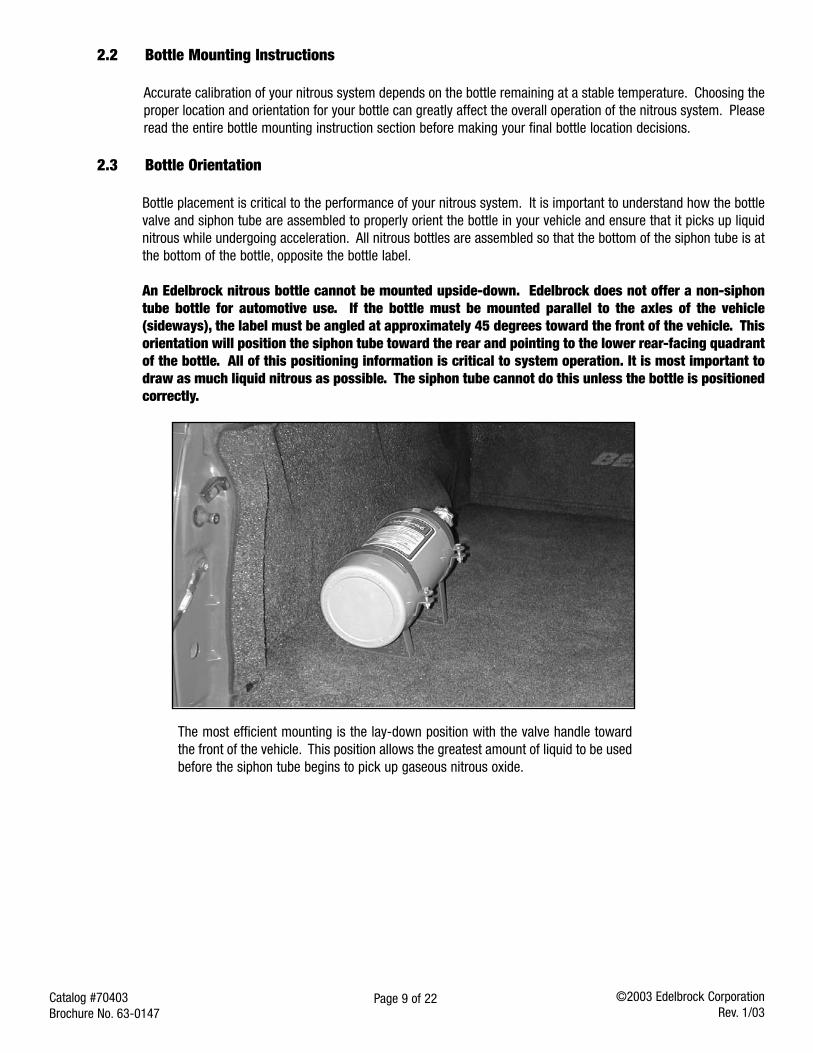
An Edelbrock nitrous bottle cannot be mounted upside-down. Edelbrock does not offer a non-siphontube bottle for automotive use. If the bottle must be mounted parallel to the axles of the vehicle(sideways), the label must be angled at approximately 45 degrees toward the front of the vehicle. Thisorientation will position the siphon tube toward the rear and pointing to the lower rear-facing quadrantof the bottle. All of this positioning information is critical to system operation. It is most important todraw as much liquid nitrous as possible. The siphon tube cannot do this unless the bottle is positionedcorrectly.
The most efficient mounting is the lay-down position with the valve handle towardthe front of the vehicle. This position allows the greatest amount of liquid to be usedbefore the siphon tube begins to pick up gaseous nitrous oxide.
Page 10 of 22Catalog #70403Brochure No. 63-0147
©2003 Edelbrock CorporationRev. 1/03
2.4 Nitrous Bottle InstallationAfter you have determined the location and orientation of the nitrous bottle, use the following procedure to installthe bottle:
2.4.1 Truck Installations1. Disconnect the vehicles battery.2. Determine the mounting location of the bottle in the truck bed. Once a mounting location has been determined,
raise the vehicle and inspect the undercarriage of the truck where the bottle is to be mounted, check to besure that there are no fuel lines, brake lines, emissions equipment, or structural members in the way ofpotential mounting bolt locations.Note: It may be necessary to remove the fuel tank depending on the location where you install the bottle.
3. Install the rubber isolators within the bottle brackets and then slip the bottle into the brackets.4. Using the bottle bracket bolt holes as templates, mark an area for each of the brackets with chalk, metal
marking pen, scribe, or marking pen to locate the bolt placements for drilling.5. Wearing safety glasses, drill two (2) 3/8” mounting holes for each bracket.
Note: If a heater blanket is used, brackets must be installed 8 ½” apart from each other.6. Install the bottle brackets using “Grade 8” bolts, nuts and flat washers (not included with kit). Use fender
washers underneath the vehicle for sheet metal mounting. Tighten the bolts using a thread locking compound(not included with kit).
2.4.2 Street Car Installations1. Disconnect vehicle’s battery.2. Determine the location of the bottle within the confines of the rear of the vehicle.3. Once a mounting location has been determined, raise the vehicle (following all safety practices involved in
working on a vehicle from under the vehicle) and verify that there are no fuel lines, fuel tank(s), brake lines,emissions equipment, or structural members in the way of potential mounting bolt locations.Note: It may be necessary to remove the fuel tank depending on the location where you install the bottle.
4. Install the rubber insulators within the bottle brackets. Slip bottle into the mounting brackets.5. Using the mounting bracket bolt holes as templates, mark an area for each of the brackets with chalk, metal
marking pen, scribe, or marking pen to locate the bolt placements for drilling.6. Wearing your safety glasses, drill two (2) 3/8” mounting holes for each bracket.7. If heater blanket is used, brackets must be installed 8 1/2 inches apart from each other.8. Install the bottle mounting brackets using “Grade 8” bolts, nuts and flat washers (not included with kit). Use
fender washer underneath the vehicle for sheet metal mounting. Tighten the mounting bolts using a threadlocking compound (not included with kit).
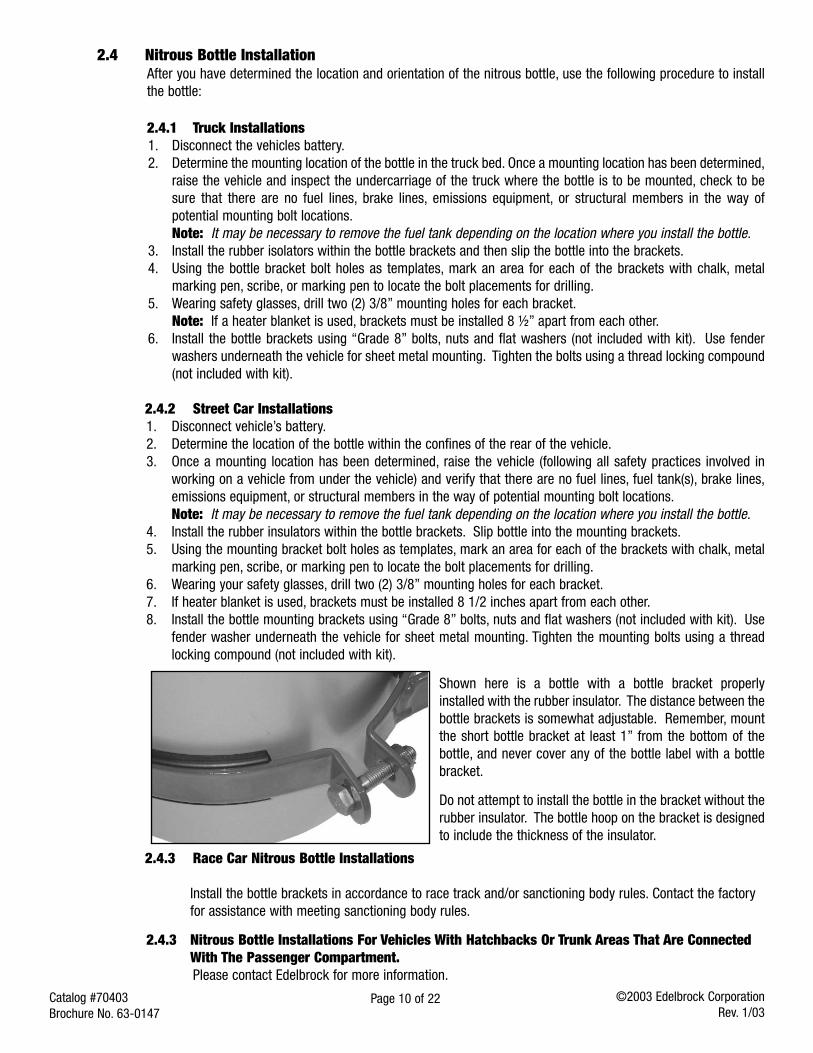
Shown here is a bottle with a bottle bracket properlyinstalled with the rubber insulator. The distance between thebottle brackets is somewhat adjustable. Remember, mountthe short bottle bracket at least 1” from the bottom of thebottle, and never cover any of the bottle label with a bottlebracket.
Do not attempt to install the bottle in the bracket without therubber insulator. The bottle hoop on the bracket is designedto include the thickness of the insulator.
2.4.3 Race Car Nitrous Bottle Installations
Install the bottle brackets in accordance to race track and/or sanctioning body rules. Contact the factoryfor assistance with meeting sanctioning body rules.
2.4.3 Nitrous Bottle Installations For Vehicles With Hatchbacks Or Trunk Areas That Are ConnectedWith The Passenger Compartment. Please contact Edelbrock for more information.
Page 11 of 22Catalog #70403Brochure No. 63-0147
©2003 Edelbrock CorporationRev. 1/03
2.5 Nitrous Feed Line Mounting1. Determine the route your main nitrous feed line will follow. Ensure the path does not route the nitrous feed
line too close to the exhaust system, suspension, electrical lines/components or tires.2. Attach nitrous supply line to bottle.3. Feed nitrous line along proposed route.4. Secure nitrous supply line to underside of vehicle.
Note: Stainless steel covering of the main nitrous feed line is very abrasive. Shield painted components orsensitive system components like electrical, fuel lines, brake lines or suspension components to preventthem from contacting main feed line. Rubber hose can be slid over and retained as a chafe guard.
5. Leave nitrous line loose pending installation of nitrous solenoid.
2.6 Solenoid Mounting
Use the following procedures to install the Performer nitrous solenoids:Note: Remember to use Teflon paste only on pipe threads. Do not use Teflon tape.Hint: Placement of the solenoid is often limited by the lack of possible mounting locations in the engine
compartment. However, if possible, observe the following suggestions:
Solenoid Safety Information1. Keep solenoid and lines away from exhaust components.2. Trial fit the solenoids with all lines attached to ensure a proper fit.3. Solenoids may be mounted sideways or upside-down, if necessary.
2.6.1 Preparing To Mount Your Solenoids1. Locate the EFI solenoid bracket, solenoid “tee”, and solenoid mounting screws.2. This solenoid bracket can be modified (bent, twisted and/or cut) to allow for easier installation in areas
with minimal clearance . Please look at the photo on the next page of a typical solenoid mountinglocation, and adapt your bracket according to the needs of your particular application.
2.6.2 Nitrous Solenoids Mounting1. Hold one of the nitrous solenoids securely (like in a bench vise) being careful not to harm the
solenoid or block the inlet or outlet of the solenoid.2. Install nitrous filter fitting (Blue fitting 4AN X 1/8 NPT) using liquid Teflon, in the inlet port of the
nitrous solenoid.3. Install one of the 1/8 NPT male sides of solenoid “tee”, using liquid Teflon, on the outlet port of the
nitrous solenoid. The female port of solenoid “tee” should be facing outward.4. Install the remaining 1/8 NPT male end of the solenoid “tee”, using liquid Teflon, into the inlet port of
the second nitrous solenoid. Rotate second solenoid so that it parallels the first.5. Install the 3AN x 1/8 NPT (blue straight fitting) into the outlet port of second nitrous solenoid.6. Install one end of the 1/8 NPT male x 1/8 NPT male nipple fitting, using liquid Teflon, into nitrous
pressure regulator inlet port.7. Loosely thread nitrous pressure regulator/nipple assembly into 1/8 NPT female port on solenoid “tee”.8. Using liquid Teflon, install 1/8 NPT x 3/16” barb fitting into nitrous pressure regulator.
i. Remove nitrous solenoid/regulator assembly from vise.ii. Attach EFI solenoid bracket to the bottom of the solenoids.ii. Verify the desired mounting location for the solenoid/regulator assembly.
9. Install solenoid/regulator assembly in desired location.10. Tighten nitrous regulator until barb fitting points towards the vehicle’s fuel pressure regulator.11. Leave all wiring loose for electrical systems installation.12. Connect main nitrous feed line to inlet fitting (4AN x 1/8 NPT nitrous filter fitting) of the first nitrous
solenoid.
Page 12 of 22Catalog #70403Brochure No. 63-0147
©2003 Edelbrock CorporationRev. 1/03
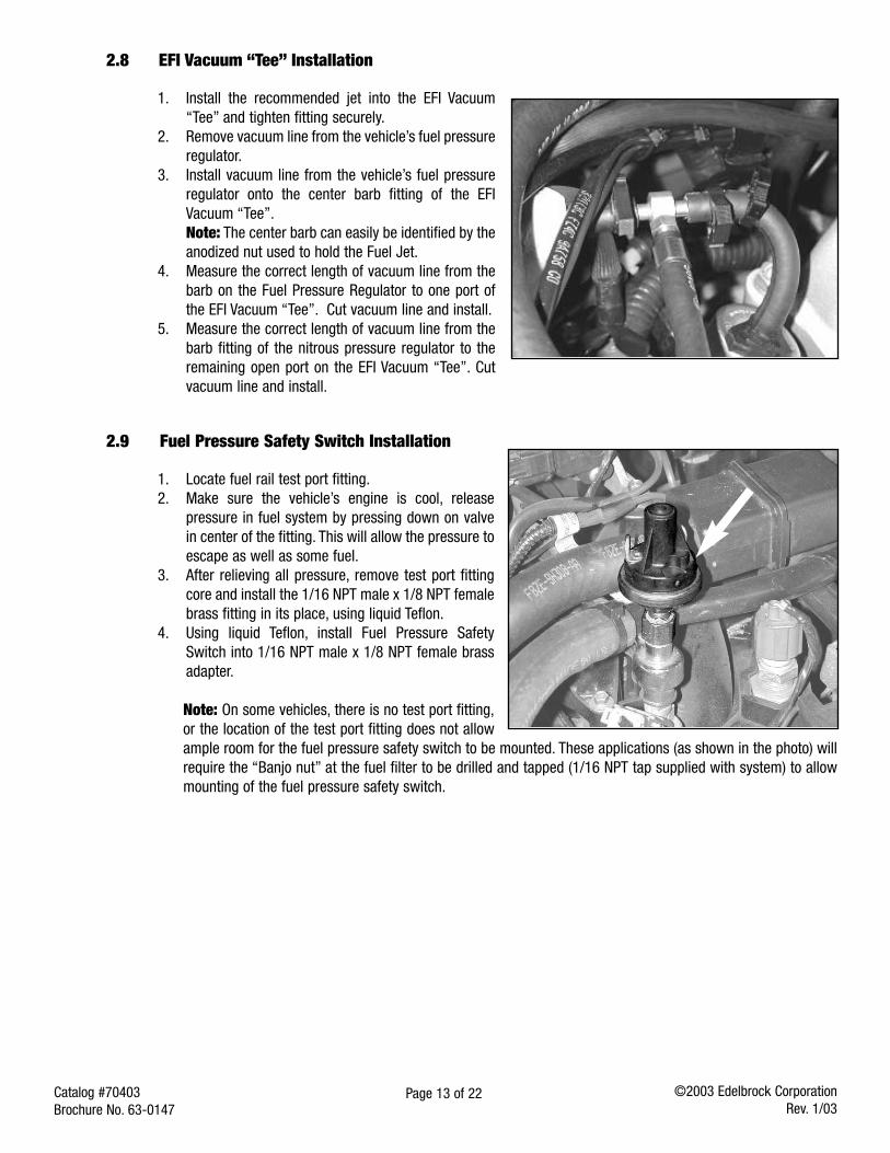
2.7 Nitrous Spray Nozzle Installation1. Determine nozzle mounting location in air inlet pipe, between air filter and throttle body, making sure the
nozzle, mounting collar, and the feed line from solenoid tonozzle, do not interfere with any systems or componentsof the vehicle.
2. Remove air inlet pipe.3. Drill a 7/16” hole in inlet pipe where nozzle placement
has been determined.4. Install nozzle mounting nut and collar onto inlet pipe.5. Install inlet pipe.6. Mark the spray direction on the nozzle.7. Using liquid Teflon, install the spray nozzle into the air
inlet pipe making sure the nozzle discharge is toward thevehicle’s engine.
8. Install recommended jet into nozzle fitting.9. Install 3AN line from solenoid outlet fitting to spray nozzle jet fitting and tighten securely.
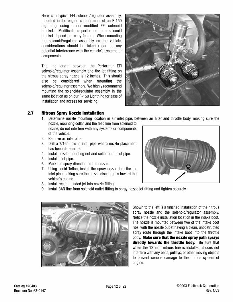
Here is a typical EFI solenoid/regulator assembly,mounted in the engine compartment of an F-150Lightning, using a non-modified EFI solenoidbracket. Modifications performed to a solenoidbracket depend on many factors. When mountingthe solenoid/regulator assembly on the vehicle,considerations should be taken regarding anypotential interference with the vehicle’s systems orcomponents.
The line length between the Performer EFIsolenoid/regulator assembly and the jet fitting onthe nitrous spray nozzle is 12 inches. This shouldalso be considered when mounting thesolenoid/regulator assembly. We highly recommendmounting the solenoid/regulator assembly in thesame location as on our F-150 Lightning for ease ofinstallation and access for servicing.
Shown to the left is a finished installation of the nitrousspray nozzle and the solenoid/regulator assembly.Notice the nozzle installation location in the intake boot.The nozzle is mounted between two of the intake bootribs, with the nozzle outlet having a clean, unobstructedspray route through the intake boot into the throttlebody. Make sure that the nozzle spray path spraysdirectly towards the throttle body. Be sure thatwhen the 12 inch nitrous line is installed, it does notinterfere with any belts, pulleys, or other moving objectsto prevent serious damage to the nitrous system ofengine.
Page 13 of 22Catalog #70403Brochure No. 63-0147
©2003 Edelbrock CorporationRev. 1/03
2.8 EFI Vacuum “Tee” Installation
1. Install the recommended jet into the EFI Vacuum“Tee” and tighten fitting securely.
2. Remove vacuum line from the vehicle’s fuel pressureregulator.
3. Install vacuum line from the vehicle’s fuel pressureregulator onto the center barb fitting of the EFIVacuum “Tee”.Note: The center barb can easily be identified by theanodized nut used to hold the Fuel Jet.
4. Measure the correct length of vacuum line from thebarb on the Fuel Pressure Regulator to one port ofthe EFI Vacuum “Tee”. Cut vacuum line and install.
5. Measure the correct length of vacuum line from thebarb fitting of the nitrous pressure regulator to theremaining open port on the EFI Vacuum “Tee”. Cutvacuum line and install.
2.9 Fuel Pressure Safety Switch Installation
1. Locate fuel rail test port fitting.2. Make sure the vehicle’s engine is cool, release
pressure in fuel system by pressing down on valvein center of the fitting. This will allow the pressure toescape as well as some fuel.
3. After relieving all pressure, remove test port fittingcore and install the 1/16 NPT male x 1/8 NPT femalebrass fitting in its place, using liquid Teflon.
4. Using liquid Teflon, install Fuel Pressure SafetySwitch into 1/16 NPT male x 1/8 NPT female brassadapter.
Note: On some vehicles, there is no test port fitting,or the location of the test port fitting does not allowample room for the fuel pressure safety switch to be mounted. These applications (as shown in the photo) willrequire the “Banjo nut” at the fuel filter to be drilled and tapped (1/16 NPT tap supplied with system) to allowmounting of the fuel pressure safety switch.
Page 14 of 22Catalog #70403Brochure No. 63-0147
©2003 Edelbrock CorporationRev. 1/03
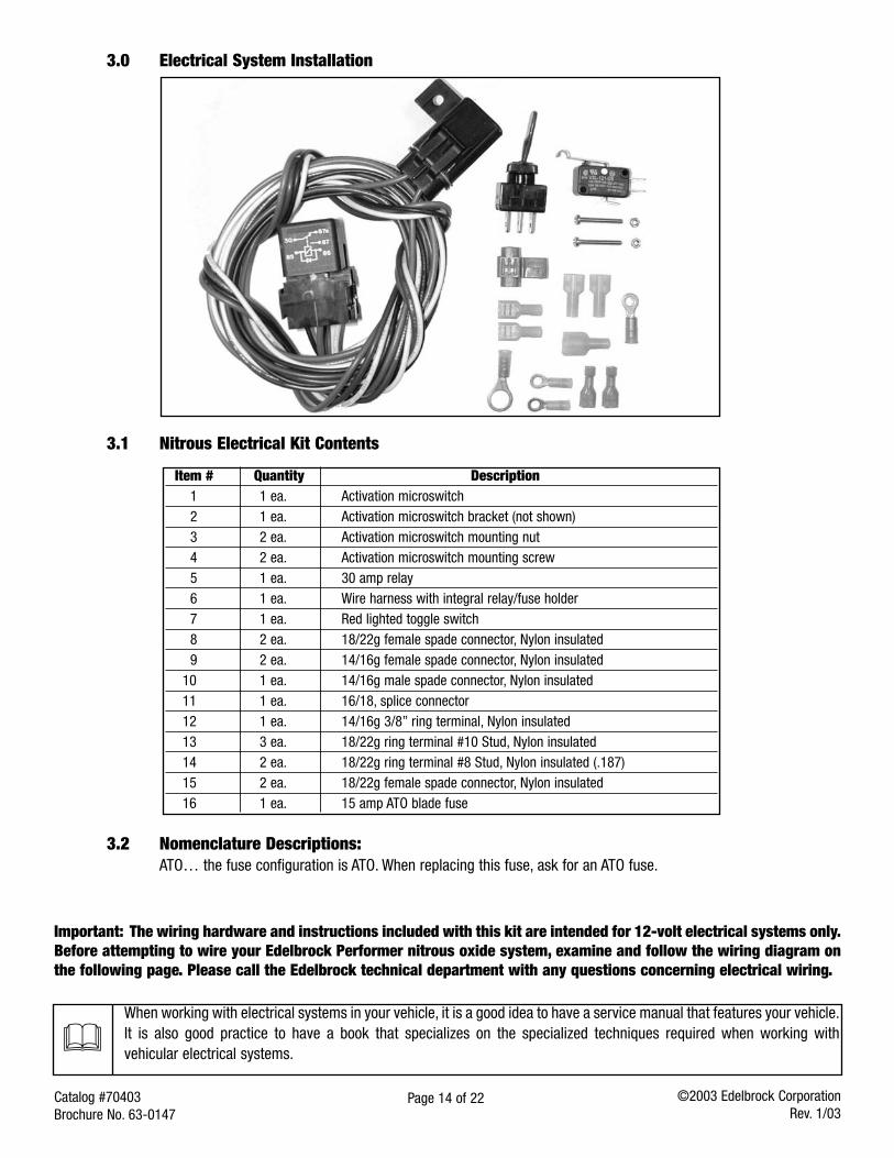
Item # Quantity Description1 1 ea. Activation microswitch2 1 ea. Activation microswitch bracket (not shown)3 2 ea. Activation microswitch mounting nut 4 2 ea. Activation microswitch mounting screw5 1 ea. 30 amp relay6 1 ea. Wire harness with integral relay/fuse holder7 1 ea. Red lighted toggle switch8 2 ea. 18/22g female spade connector, Nylon insulated9 2 ea. 14/16g female spade connector, Nylon insulated
10 1 ea. 14/16g male spade connector, Nylon insulated11 1 ea. 16/18, splice connector12 1 ea. 14/16g 3/8” ring terminal, Nylon insulated13 3 ea. 18/22g ring terminal #10 Stud, Nylon insulated14 2 ea. 18/22g ring terminal #8 Stud, Nylon insulated (.187)15 2 ea. 18/22g female spade connector, Nylon insulated16 1 ea. 15 amp ATO blade fuse
3.1 Nitrous Electrical Kit Contents
3.0 Electrical System Installation
Important: The wiring hardware and instructions included with this kit are intended for 12-volt electrical systems only.Before attempting to wire your Edelbrock Performer nitrous oxide system, examine and follow the wiring diagram onthe following page. Please call the Edelbrock technical department with any questions concerning electrical wiring.
3.2 Nomenclature Descriptions:ATO… the fuse configuration is ATO. When replacing this fuse, ask for an ATO fuse.
When working with electrical systems in your vehicle, it is a good idea to have a service manual that features your vehicle.It is also good practice to have a book that specializes on the specialized techniques required when working withvehicular electrical systems.
BATT
ERY
FUSE
RE
LAY
SOCK
ET
SOCK
ET
SWIT
CHED
+12
V
ARM
ING
SWIT
CH
SOLE
NOID
SOLE
NOID
FUEL
PRE
SSUR
ESA
FETY
SW
ITCH
WAR
NING
!DO
NOT
CON
NECT
TO T
HIS
TERM
INAL
MIC
ROSW
ITCH
RED
WHI
TE
BLAC
K
BLUE
RED
SUPP
LY+1
2vON AC
CGR
OUND -
12
16
11
7
8
11
13
14
910
13
2 3 41
13
15
13
5 6
(2)
(2)
(2)
(2)
©20
02 E
delb
rock
Cor
pora
tion
Rev.
1/03
Page
15
of 2
2Ca
talo
g #7
0403
Broc
hure
No.
63-0
247
Page 16 of 22Catalog #70403Brochure No. 63-0147
©2003 Edelbrock CorporationRev. 1/03
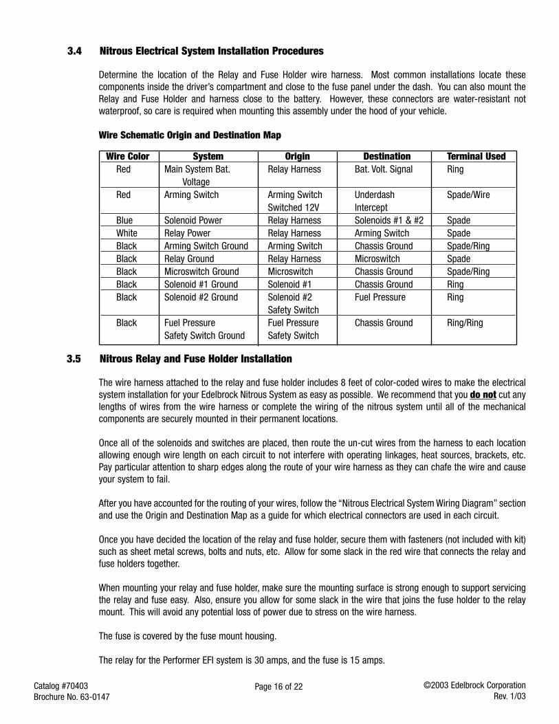
3.4 Nitrous Electrical System Installation Procedures
Determine the location of the Relay and Fuse Holder wire harness. Most common installations locate thesecomponents inside the driver’s compartment and close to the fuse panel under the dash. You can also mount theRelay and Fuse Holder and harness close to the battery. However, these connectors are water-resistant notwaterproof, so care is required when mounting this assembly under the hood of your vehicle.
Wire Schematic Origin and Destination Map
Wire Color System Origin Destination Terminal UsedRed Main System Bat. Relay Harness Bat. Volt. Signal Ring
VoltageRed Arming Switch Arming Switch Underdash Spade/Wire
Switched 12V InterceptBlue Solenoid Power Relay Harness Solenoids #1 & #2 SpadeWhite Relay Power Relay Harness Arming Switch SpadeBlack Arming Switch Ground Arming Switch Chassis Ground Spade/RingBlack Relay Ground Relay Harness Microswitch SpadeBlack Microswitch Ground Microswitch Chassis Ground Spade/RingBlack Solenoid #1 Ground Solenoid #1 Chassis Ground RingBlack Solenoid #2 Ground Solenoid #2 Fuel Pressure Ring
Safety SwitchBlack Fuel Pressure Fuel Pressure Chassis Ground Ring/Ring
Safety Switch Ground Safety Switch
3.5 Nitrous Relay and Fuse Holder Installation
The wire harness attached to the relay and fuse holder includes 8 feet of color-coded wires to make the electricalsystem installation for your Edelbrock Nitrous System as easy as possible. We recommend that you do not cut anylengths of wires from the wire harness or complete the wiring of the nitrous system until all of the mechanicalcomponents are securely mounted in their permanent locations.
Once all of the solenoids and switches are placed, then route the un-cut wires from the harness to each locationallowing enough wire length on each circuit to not interfere with operating linkages, heat sources, brackets, etc.Pay particular attention to sharp edges along the route of your wire harness as they can chafe the wire and causeyour system to fail.
After you have accounted for the routing of your wires, follow the “Nitrous Electrical System Wiring Diagram” sectionand use the Origin and Destination Map as a guide for which electrical connectors are used in each circuit.
Once you have decided the location of the relay and fuse holder, secure them with fasteners (not included with kit)such as sheet metal screws, bolts and nuts, etc. Allow for some slack in the red wire that connects the relay andfuse holders together.
When mounting your relay and fuse holder, make sure the mounting surface is strong enough to support servicingthe relay and fuse easy. Also, ensure you allow for some slack in the wire that joins the fuse holder to the relaymount. This will avoid any potential loss of power due to stress on the wire harness.
The fuse is covered by the fuse mount housing.
The relay for the Performer EFI system is 30 amps, and the fuse is 15 amps.
Page 17 of 22Catalog #70403Brochure No. 63-0147
©2003 Edelbrock CorporationRev. 1/03
3.6 Arming Switch and Installation
The arming switch is a red, lighted switch that is a "MASTER" arming switch for your nitrous system. Without it,your nitrous system would be "on" all of the time and capable of engaging anytime you go to wide-open throttleconditions with your vehicle. The switch, when in the "armed" position, is well lit. Therefore, it should be placed inan obvious position well within the line of sight and easy reach of the driver. Please refer to the procedures belowfor the installation of the arming switch:
1. Locate the final position of your arming switch.2. Drill a 1/2" hole for the switch location.3. Insert the switch from behind the mounting hole and secure with the switch nut.4. Do not wire until all other mechanical components are in place. Please see the electrical system installation
instructions for further information.
Note: There is a collar included with the switch for applications that require special spacing duringinstallation.
3.7 Microswitch Installation and Wiring
The function of your microswitch is to enable your nitrous system. It should be installed so that the switch is forcedclosed by coming in contact with the throttle linkage only at the wide open throttle position. The nitrous systemmust only function at fully-loaded wide-open throttle.
MICROSWITCH SAFETY INFORMATION
1. Do not allow wiring from the microswitch to come in contact with heat sources on the intake manifold suchas EGR risers or passageways.
2. Do not run wires to the microswitch that can create interference with the operation of the throttle linkage.3. The microswitch must be located in such a way as to be clear of the normal operation of the throttle linkage.4. Do not directly expose the microswitch to liquids such as water or gasoline.
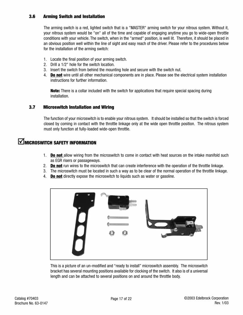
This is a picture of an un-modified and “ready to install” microswitch assembly. The microswitchbracket has several mounting positions available for clocking of the switch. It also is of a universallength and can be attached to several positions on and around the throttle body.
Page 18 of 22Catalog #70403Brochure No. 63-0147
©2003 Edelbrock CorporationRev. 1/03
3.7 Microswitch Installation and Wiring (Continued)
The bolts used to attach the microswitch have extra length to allow for spacing the microswitch away from thebracket if necessary. After determining the position of the microswitch, we recommend trimming the bolts for aclean installation.
Due to the wide variety of throttle linkage combinations in use, it is impossible to supply a microswitch bracketcustom-tailored to each application. The universal bracket-supplied will need to be modified to fit your specificapplication.
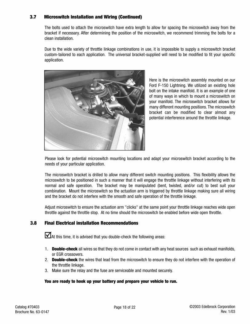
Here is the microswitch assembly mounted on ourFord F-150 Lightning. We utilized an existing holebolt on the intake manifold. It is an example of oneof many ways in which to mount a microswitch onyour manifold. The microswitch bracket allows formany different mounting positions. The microswitchbracket can be modified to clear almost anypotential interference around the throttle linkage.
Please look for potential microswitch mounting locations and adapt your microswitch bracket according to theneeds of your particular application.
The microswitch bracket is drilled to allow many different switch mounting positions. This flexibility allows themicroswitch to be positioned in such a manner that it will engage the throttle linkage without interfering with itsnormal and safe operation. The bracket may be manipulated (bent, twisted, and/or cut) to best suit yourcombination. Mount the microswitch so the actuation arm is triggered by throttle linkage making sure all wiringand the bracket do not interfere with the smooth and safe operation of the throttle linkage.
Adjust microswitch to ensure the actuation arm "clicks" at the same point your throttle linkage reaches wide openthrottle against the throttle stop. At no time should the microswitch be enabled before wide open throttle.
3.8 Final Electrical installation Recommendations
At this time, it is advised that you double-check the following areas:
1. Double-check all wires so that they do not come in contact with any heat sources such as exhaust manifolds,or EGR crossovers.
2. Double-check the wires that lead from the microswitch to ensure they do not interfere with the operation ofthe throttle linkage.
3. Make sure the relay and the fuse are serviceable and mounted securely.
You are ready to hook up your battery and prepare your vehicle to run.
Page 19 of 22Catalog #70403Brochure No. 63-0147
©2003 Edelbrock CorporationRev. 1/03
4.0 Before You Run Your Vehicle Using Your Edelbrock Nitrous System
You have just completed the installation of your Edelbrock Nitrous System. It is time to perform some basic systemchecks to ensure all of the work you have done is correct and ready to operate properly. The following procedureis designed to validate the operation of your nitrous system before operating your vehicle:
Note: Before performing steps 1 through 5, make sure that the nitrous bottle is closed and main nitroussupply line is empty of any nitrous.
4.1 Fuel System Check1. Hook up all battery leads.2. Double-check all wires and leads for signs of heat and proper connections.3. Turn the ignition key to the engine "on" position without starting the engine.4. Inspect fuel rail where Fuel Pressure Safety Switch has been installed for any leaks.5. Inspect fuel booster pump and fuel lines for any leaks.
4.2 Nitrous System Check1. With the vehicle's engine running, slowly open nitrous bottle valve.
Note: There should be no change in engine idle speed. If idle speed changes, close nitrous bottle valveimmediately and refer to the "Troubleshooting and Routine Maintenance” Section.
2. Inspect nitrous lines and fittings for leaks using a soapy water mixture and a small brush.3. If any of the fittings/connections show bubbling around the attachment nut or on the threaded area of
the fitting, shut the nitrous bottle valve off immediately and dry the fitting before attempting any serviceto that particular fitting connection.
4. If the engine idle does not come up, and all of the fittings appear to be leak-free, you have successfullycompleted the installation of you Edelbrock Nitrous System.
6.0 Solenoid Inspection and Maintenance.
1. Close valve on nitrous bottle.2. Make sure all nitrous supply lines are free of pressure before removal of any system solenoid.
a. Empty main nitrous supply line at the nitrous bottle. Take care to not breathe or expose your skin to nitrous.b. Do not open pressurized fuel lines over a hot engine.
3. Remove nitrous solenoid from the engine and securely clamp it into a vise, taking great care not to damage the solenoid.4. Remove the solenoid cover, retaining nut from top of the nitrous solenoid.5. Remove coil and housing from nitrous solenoid base.6. Unscrew stem from nitrous solenoid base. Do this by using a solenoid stem removal tool or by “double nutting” the
stem and unscrewing the stem from the housing body. Do not use pliers on solenoid stem; damage to the stemwill result.
7. Carefully remove the stem, spring and plunger from the solenoid base paying close attention to the way they areassembled.
8. Examine the plunger seal for swelling, cuts and abrasions. The seal surface should be flat, except for a small circularindentation in the center of the seal. A seal that has been contaminated or over-pressurized will bulge from exposureto chemicals other than nitrous oxide. It can appear to extend down from the plunger and be dome-shaped. Acontaminated seal may return to its original shape if left out in fresh air for approximately 48 hours. It may then bereturned to service. If it does not return to its original shape, it must be replaced.
9. Clean the solenoid body. Do not use an oil-based solvent to clean any part of the solenoid. Use paint thinneror electrical contact cleaner. Remove any contaminants that may be present. Make sure solenoid body is clean, dryand free of oils before assembly.
10. Replace the O-Ring, plunger and piston spring.11. Re-assemble solenoid by reversing disassembly procedure.
Page 20 of 22Catalog #70403Brochure No. 63-0147
©2003 Edelbrock CorporationRev. 1/03
5.0 Troubleshooting and Routine Maintenance
How to use our Troubleshooting Flowchart:
The troubleshooting of a nitrous system is basic and straightforward. The symptom chart is divided by symptom,cause and action required. Determine your problem (symptom), identify the potential problem (cause) and correctthe problem (action required).
Symptom #1… Change in engine speed when nitrous bottle valve is opened.
1. Malfunctioning nitrous solenoid.a. Refer to “Solenoid Inspection and Maintenance” section.b. Repair/replace solenoid.
2. Contamination in nitrous solenoid.a. Refer to “Solenoid Inspection and Maintenance” section.b. Clean/replace solenoid.
Symptom #2… Engine runs excessively rich when system is activated.
1. Nitrous bottle valve not fully opened.a. Check bottle valve.b. Open valve fully.
2. Nitrous bottle mounted improperly.a. Mount bottle properly. Refer to “Nitrous Bottle Mounting” section.
3. Plugged nitrous filter.a. Clean and/or replace nitrous filter.b. See nitrous solenoid symptom #1.
4. Low bottle pressure.a. Weigh bottle.
1. Bottle should be 10 lbs. above empty, bottle weight listed on bottle label.b. Check bottle temperature.
1. Maintain 80 to 85 degrees of bottle surface temperature.
Symptom #3… No change in performance when system is activated.
1. System wired incorrectly.a. Compare wiring to schematic. Refer to “Nitrous Electrical System Installation Procedures” section.b. Wire per instructions.
2. Loose ground wires.a. Connect test light to battery "+" (positive) terminal. Check for continuity at grounds.b. Tighten/repair loose grounds.
3. No power to arming switch.a. With ignition "on", connect test light to battery "-" (negative) terminal. Check for power at pole
#1 on arming switch.b. Repair wiring as necessary.
Page 21 of 22Catalog #70403Brochure No. 63-0147
©2003 Edelbrock CorporationRev. 1/03
4. Malfunctioning arming switch.a. With ignition "on", turn arming switch "on." Connect test light to battery "-" (negative) terminal.
Check for power at terminal #1 wire on arming switch.b. If power is present, replace arming switch.
5. Malfunctioning microswitch.a. Turn arming toggle "off". Close throttle microswitch, check for continuity between microswitch
wiring terminals.b. If continuity is present, replace microswitch.
6. Inadequate nitrous supply.a. Weigh bottle.
1. Bottle should be 10 lbs. above empty bottle weight listed on bottle label when full.b. Check bottle pressure.
1. Maintain 900-950 psi for optimum system performance.c. Check bottle temperature.
1. Maintain 80 to 85 degrees of bottle surface temperature.d. Check bottle valve.
1. Open valve fully.e. Check bottle orientation. Refer to “Bottle Mounting Orientation” section.
1. Mount bottle properly.
7. Incorrect nitrous jetting.a. Compare jetting to recommended values. Refer to “Jet Map Information” section.
1. Install correct jetsb. Verify the number stamped in the jet.
1. Acquire the right size jets and install correct jets.
8. Loose nitrous solenoid wiring.a. Inspect solenoid wiring. Refer to “Nitrous Electrical System Wiring Diagram” section.b. Repair wiring as necessary.
9. Malfunctioning nitrous solenoid.a. Inspect solenoid wiring. Refer to “Nitrous Electrical System Wiring Diagram” section.
1. Repair wiring as necessary.b. Inspect solenoid. See symptom # 2.
1. Rebuild/replace solenoid.
Symptom #4… Engine detonates mildly when system is activated.
1. Excessive ignition timing.a. Check Timing.
1. Reduce timing in 2-degree increments for every 50 hp.
2. Inadequate octane fuel.a. Verify what gasoline you use.
1. Use higher-octane fuel.
Page 22 of 22Catalog #70403Brochure No. 63-0147
©2003 Edelbrock CorporationRev. 1/03
3. Spark plug heat range too high.a. Verify what heat range the spark plug is, and how it functions in a high load, high
performance application.1. Install a performance spark plug.2. Reduce spark plug heat range.
4. Too much nitrous flow.a. Verify the size of the nitrous jet.
1. Install the proper nitrous jet.b. Check bottle temperature and pressure.
1. Ensure before every nitrous usage that you only use nitrous when the temperature andpressure of your bottle are correct.
Symptom #5… Vehicle surges under acceleration when system is activated.
1. Inadequate nitrous supply.a. Weigh bottle.
1. Bottle should be 10 lbs. above empty bottle weight listed on bottle label when full.b.Check bottle temperature.
1. Maintain 80 to 85 degrees of bottle surface temperature.c. Check bottle valve.
1. Open valve fullyd.Check bottle orientation. Refer to “Nitrous Bottle Mounting” section.
1. Mount bottle properly.