Embed Size (px)
Citation preview
71-1920-2504/97
CAUTION—ELECTRIC TOYNOT RECOMMENDED FOR CHILDREN UNDER EIGHT YEARS OF AGE. AS WITH ALL ELECTRIC PRODUCTS, PRECAUTIONS SHOULD BE OBSERVEDDURING HANDLING AND USE TO REDUCE THE RISK OF ELECTRIC SHOCK. TRANSFORMER RATINGS—INPUT: 120 VAC; 60 HZ ONLY. AC OUTPUT: 18 V; 54 VA, 3.0 AMPS
Owner’s Manual

Congratulations!
22
You’re now the proud owner of thePort of Lionel City ready-to-run
O-27 set. Everything you need to getstarted is included. You’re already offto a great start by reading this instruc-tion manual. It has important informa-tion on train setup and operation. Thisbooklet also covers proper mainte-
nance procedures to help your Lioneltrains live long, healthy lives.
If you have any questions after read-ing this booklet, contact your nearestauthorized Lionel Service Center usingthe list included in a separate flier in thisset or Lionel Service at 810-949-4100.
And have fun!
Table of contents
Track layoutGetting started 3Suggested track layouts 3Joining the track sections 4Grade crossing 4Attaching the lockon to the track 5
Controller operationsStripping the wire 6Attaching the controller wires to the lockon 6Controller functions 7Controller and short circuits 8
Train operationsReverse unit procedure 9Coupling 10Using your FA2’s magnetic coupler 10
Maintaining and servicing your setLubricating your FA2 diesel locomotive 11Enhanced tractive effort 11Replacing your FA2’s headlight 12Replacing your searchlight car’s lamp 13Replacing your medical caboose’s interior lamp 13Speed boat operation and battery replacement 14Derrick car setup and operation 15Setting up the derrick 15Raising and lowering the boom 15Radar car assembly and lamp replacement 16Lionel Service 16

Track layout
33
Getting started
Before you do anything else, we rec-ommend you check the contents of
your set box to ensure all of the parts ofyour set have been included and thatthe quantities (when applicable) arecorrect.
The parts list below will tell youwhat’s included and the correct quanti-ties. If you find any discrepancies, con-tact the dealer that you purchased itfrom for more information or callLionel Service at 810-949-4100.
Now comes the fun part—decidingwhat kind of layout you want.
The only rule—let your imagination beyour guide.
• FA2 diesel locomotive 1• Searchlight car 1• Radar car 1• Derrick car 1• Flatcar and speed boat 1• Medical caboose (lighted) 1
(includes 1 figure, 3 stretchers,and 1 oxygen tank )
• Tractor/trailer 1
• Controller 1• 40-watt power pack 1• Lockon 1• Straight track 8• Curved track 8• Grade crossing 2• Service Center list 1• Railroader Club application 1• Warranty card 1
Suggested track layouts
Here are some examples of layouts you can build with 8 straight and 8 curved sections oftrack. Remember—the more track you purchase, the more variations you can create in yourtrain layout. And that means more fun!

Track layout
Joining the track sections
44
Join the track sections together by inserting the
pins of one track sec-tion into the railopenings of another.For good electricalcontact, pins mustbe carefully insertedand track jointstightly fitted.
If the track is diffi-cult to connect, trythis installation tip.You can “break in”O-27 track sectionsby inserting andwithdrawing a trackpin into one rail at atime before joiningthe entire track sec-tion. If the openingsbecome too open(causing the track to fit loosely), pinch
the rail together around a track pinwith a pair of pliers.If any pins fall outof the track and aremissing, replacethem with extrasavailable from yourLionel dealer.
Maintenance tip:The rails should bekept clean, dry, andfree from oil andgrease. Clean rustand dirt spots with atrack eraser. Wipethe track using acloth dampenedwith track cleanerfrom the Lionelmaintenance kit (no.6-62927), which isavailable from your
authorized Lionel Value Added Dealer.
Grade crossing
Included in your Port of Lionel Cityset are two pieces of grade
crossing. These can be usedon any straight section oftrack and will allow you todrive your Lionel tractor-trailer, as well as other toy cars andtrucks, over the rails of your layout.
To install, place the grade crossingunder a section of straighttrack, lining up the railswith the grooves in thecrossing. You may installtwo crossings on the same
section of track or on separate sec-tions.
Attaching the lockon to the track
55
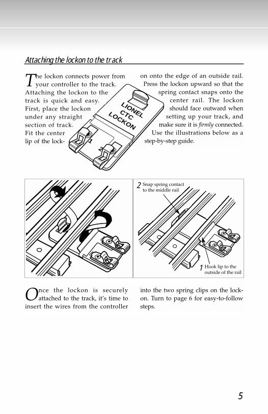
The lockon connects power fromyour controller to the track.
Attaching the lockon to thetrack is quick and easy.First, place the lockonunder any straightsection of track.Fit the centerlip of the lock-
on onto the edge of an outside rail.Press the lockon upward so that the
spring contact snaps onto thecenter rail. The lockonshould face outward when
setting up your track, andmake sure it is firmly connected.
Use the illustrations below as astep-by-step guide.
Once the lockon is securelyattached to the track, it’s time to
insert the wires from the controller
into the two spring clips on the lock-on. Turn to page 6 for easy-to-followsteps.
21
LIONEL CTCLOCKON
Snap spring contactto the middle rail
2
Hook lip to theoutside of the rail
1

Controller operations
66
OFF
FULL
SPEED
R
Attaching the controller wires to the lockon
Now you’ll need to insert a controllerwire into each of the two spring
clips on the lockon. It’s easy! Depress thespring clip with your finger and insertthe bare end of the wire into theexposed opening. Release the spring
clip. Give the wire a little tug to makesure it’s secure. Repeat these steps withthe other spring clip. Next, insert thesmall plug end of the power pack intothe back of your controller, and plug theother end into a standard outlet.
Plug this end intoback of controller.
Stripping the wire
Once your track is assembled andthe lockon is
securely attached,you can connectthe wires fromthe controller tothe lockon.
First you‘ll wantto check the ends of thewires to make sure that the insulation is
stripped back about 1⁄4" to 3⁄8". To stripthe wires, use a pair of
wire strippersor a sharp
knife. C a u t i o n :
Only an adultshould per-
form this task!Always use care when stripping wires.
Plug power packinto standard
wall outlet
Make sure that the bare endof each wire is securelyattached to the spring clip.
77
Controller functions
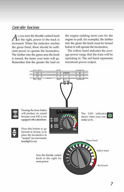
As you turn the throttle control knobto the right, power to the track is
increased. When the indicator reachesthe green band, there should be suffi-cient power to operate the locomotive.The further into the green area the knobis turned, the faster your train will go.Remember that the greater the load on
the engine (adding more cars for theengine to pull, for example), the fartherinto the green the knob must be turnedbefore it will operate the locomotive.
The yellow band indicates the aver-age power range that the train will beoperating in. The red band representsmaximum power output.
FULLFULLSPEEDSPEED
OFFOFF
R
FULLSPEED
OFF
FULLSPEED
OFF
Pressing the horn buttonwill produce no soundbecause your FA2 is notequipped with a diesel horn.
Press this button to goforward or reverse, or toplace the locomotive in“neutral” (no movement,headlight is on).
Turn the throttle controlknob to the right formore power.
The LED indicatorshows when your con-troller is ON.
Green band
Yellow band
Red band
FULLSPEED
OFF
FULLSPEED
OFF

Controller operations
88
Your Lionel power pack is listed byUnderwriters Laboratories Inc. and
has been carefully designed and testedto ensure peak performance. The con-troller is equipped with a built-in elec-tronic circuit breaker that alternatelycuts off and restores the flow of powerto the track whenever a short circuitexists—for example, when the trainderails. The circuit breaker’s action con-tinues until the cause of the short circuitis eliminated. This circuit breaker isincorporated into the controller to pro-tect it from possible damage. It will notprotect the locomotive or electricallyoperated accessories, so it’s importantto eliminate short circuits as soon aspossible.
A short circuit is caused by a directconnection between the center rail andone of the outside rails or by a directconnection between bare wires. Theaxles of a derailed car or locomotive are
the most frequent cause of short circuits,so make sure that all wheels are proper-ly set on the rails. Some other causes ofshort circuits might be staples, nails,paper clips, or other metallic objectslying across the rails, or two bare wirestouching each other.
If too many cars or accessories areused, your controller will exceed itspower limit and begin to cycle on andoff. To correct this problem, cars oraccessories must be removed beforenormal operation can resume. The samecondition can occur if the power isturned up too quickly. This also couldcause your train to move too fast andderail.
After your power pack has been oper-ating for a while, you will find it warmto the touch. It is the nature of all electri-cal power equipment to become warmwhen in use. If your controller is loadedto capacity, it is a good idea to let it cooldown after an hour or two of continu-ous use. Always unplug the powerpack from the wall when the controlleris not in use.
For more power, see the line of Lionelhigh-output transformers at yourauthorized Lionel Value Added Dealer.
The power pack must beunplugged from the wallsocket when a short circuit isnoticed, and the short circuitmust be corrected.
Note!
Controller and short circuits

Train operations
99
Reverse unit procedure
The reverse unit inside your LionelFA2 is an electronic device that acts
like the transmission in your car. Whenyou apply power to the track, the loco-motive moves in the direction specifiedby the reverse unit—or it sits in neutral,awaiting anotherpower interruption.Power interruptionsare the signal thattells the reverse unitto sequence to thenext operational state.
To interrupt powerand sequence thelocomotive’s reverseunit, press the direc-tion control button orturn the throttle to theOFF position and ON again. The reverseunit alternates between three states:forward, neutral, and reverse.
Also, the locomotive can be “locked”into a certain mode of operation bythrowing the switch located on theunderside of the frame (see illustrationabove). When the switch is thrown to theOFF position, the locomotive will belocked in the next mode of operation in
the sequence. For instance, if the locomo-tive is moving forward, then is stoppedand the switch is thrown back, the loco-motive will be “locked” in neutral. If theswitch is thrown back while the locomo-tive is under power, the locomotive will
remain in the mode itwas in when theswitch was thrown.The controller direc-tion control will thenhave no effect on thedirection of the loco-motive.
Additionally, thisreverse unit has a“power-up reset”feature, whichmeans that should
the locomotive sit without power for ashort period of time, the reverse unitwill automatically reset and start in theforward direction when the trans-former is turned on or “powered up,”regardless of the locking switch posi-tion. If the locking switch is in the OFF
position, the locomotive will start inthe forward direction and be “locked”there.
OFF
FULL
SPEED
R
Direction controlbutton
Horn controlbutton
ON
OFF
Position your reverse unit switch to theOFF position to deactivate it.

1010
Coupling
After you have assembled the track,place the locomotive and rolling
stock on the track. Before coupling thecars, make sure the wheels are proper-ly set on the rails.
When coupling your cars, at least one
of the mating couplers must be open asshown below at the left. Now simplypush the cars toward each other untilthey lock together.
Now you’re ready to pull out of thestation. All aboard!
Keep in mind that it’s easier to couple cars on a straight stretch of track.
Push down thelock release toopen the coupler.
Train operations
Using your FA2’s magnetic coupler
Your FA2 locomotive is equippedwith an operating magnetic knuck-
le coupler, a revolu-tionary design firstintroduced by Lionelin 1945.
Lionel magneticcouplers react to themagnetic field gen-erated by a Lionelremote-control tracksection (availableseparately).
Place the couplertrigger disc over thecentral coil of a remote-control track sec-tion and press UNCOUPLE on the con-troller. The magnetic field pulls the disc
downward, and the knuckle opens. One operating technique favored by
Lionel railroaders isthe “moving uncou-ple.” Press theUNCOUPLE button asthe locomotivepasses over aremote-control tracksection. The mag-netic field will openthe coupler; the con-sist remains behindas the locomotivemoves on. But be
careful—the speed of a newly uncou-pled and moving locomotive canincrease dramatically.
Position the coupler’s trigger disc overthe remote-control section, then pressUNCOUPLE. The coupler opens.

1111
Maintaining and servicing your set
Enhanced tractive effort
Y our locomotive is equipped withTire-Traction™. This means that
two of the drive wheels on each truckare fitted with rubber traction tires toenhance tractive effort so your loco-
motive can pull many cars at once. Lionel locomotives with Tire-
Traction grip the track, enablingthem to pull heavy loads at higherspeeds.
Help your Lionel FA2 lead a longand productive life on your rail-
road by maintaining it properly. We recommend you purchase a
Lionel Lubrication and MaintenanceKit (no. 6-62927), available from yourLionel dealer. Two basic rules to keepin mind: never over-lubricate (a smallamount will do), and avoid getting
grease or oil on the FA2’s wheels, con-tact rollers, or your track.
You’ll know your FA2 requires lubri-cation when visual inspection revealsdryness on the parts indicated in theillustration. Remove accumulated dirtand dust before lubricating, and alwayslubricate any locomotive emerging fromprolonged storage.
Lubricating your FA2 diesel locomotive
LUBRICATE WITHLIONEL OILSPARINGLY
LUBRICATE WITHLIONEL OILSPARINGLY
LUBRICATE WITHLIONEL OIL
SPARINGLY
LUBRICATE WITHLIONEL GREASE
LUBRICATE WITHLIONEL GREASE

1212
Maintaining and servicing your set
To replace your FA2’s headlamp,first remove the four chassis
screws on the underside of the locomo-tive. Carefully lift off the body.
Pull the lamp straight up and out ofthe lamp housing and replace it with
Lionel part no. 600-8352-311, avail-able from your local authorizedLionel Service Center or LionelService.
For more service information, see theLionel Service section on page 16.
Replacing your FA2’s headlamp
Lionel part no. 600-8352-311
Lamp housing
Remove the two front andtwo rear chassis screws.

Replacing your searchlight car’s lamp
Replacing your medical caboose’s interior lamp
Searchlight housing
Metal tabs
Lionel part no. 600-8352-311
To replace the lamp in your search-light car, first remove
the searchlight housingby spreading apartthe metal tabs andcarefully lifting thehousing upwards.
Pull the lamp straight up and replace itwith Lionel part no. 600-8352-311,
available from your local autho-rized Lionel Service Center orLionel Service.
Reinsert the searchlight housinginto the metal tabs.
To replace the lamp inside thecaboose cab, carefully pull the cab
straight up until the fourtabs have cleared theslots on the frame. Alsomake sure the ladder onthe end platform clearsthe slot on the roof of thecab.
Next, remove the bulb from
the lamp socket by pulling it straightup. Replace it with
Lionel part no. 600-8352-311, available at
your local authorizedLionel Service Center or
Lionel Service.Replace the cab,making sure that theladder fits back intothe slot on the roof.
1313
Lionel part no. 600-8352-311
Maintaining and servicing your set
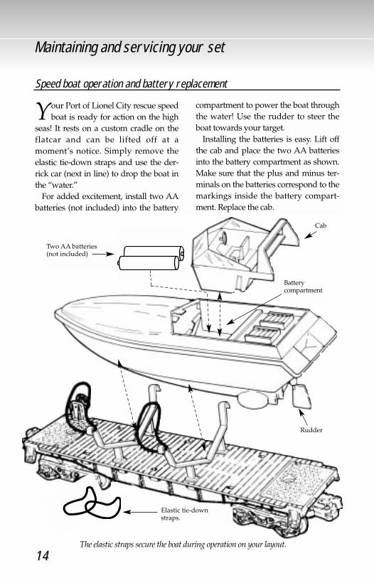
Your Port of Lionel City rescue speedboat is ready for action on the high
seas! It rests on a custom cradle on theflatcar and can be lifted off at amoment’s notice. Simply remove theelastic tie-down straps and use the der-rick car (next in line) to drop the boat inthe “water.”
For added excitement, install two AAbatteries (not included) into the battery
compartment to power the boat throughthe water! Use the rudder to steer theboat towards your target.
Installing the batteries is easy. Lift offthe cab and place the two AA batteriesinto the battery compartment as shown.Make sure that the plus and minus ter-minals on the batteries correspond to themarkings inside the battery compart-ment. Replace the cab.
Battery compartment
Cab
Rudder
Two AA batteries (not included)
Elastic tie-down straps.
AA SIZE BATTERY
AA SIZE BATTERY
Speed boat operation and battery replacement
The elastic straps secure the boat during operation on your layout.
1414
Derrick car setup and operation
Raising and lowering the boom
Setting up the derrick
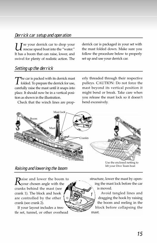
The car is packed with its derrick mastfolded. To prepare the derrick for use,
carefully raise the mast until it snaps intoplace. It should now be in a vertical posi-tion as shown in the illustration.
Check that the winch lines are prop-
erly threaded through their respectivepulleys. CAUTION: Do not force themast beyond its vertical position itmight bend or break. Take care whenyou release the mast lock so it doesn’tbend excessively.
U se your derrick car to drop yourrescue speed boat into the “water.”
It has a boom that can raise, lower, andswivel for plenty of realistic action. The
derrick car is packaged in your set withthe mast folded down. Make sure youfollow the procedure below to properlyset up and use your derrick car.
Raise and lower the boom toyour chosen angle with the
cranks behind the mast (seecrank 1). The block and hookare controlled by the othercrank (see crank 2).
If your layout includes a tres-tle set, tunnel, or other overhead
structure, lower the mast by open-ing the mast lock before the car
is moved. Avoid tangled lines and
dragging the hook by raisingthe boom and reeling in the
block before collapsing themast.
Boom
Mast
Cranks
Use the enclosed netting tolift your Dive Team boat
12
Mast lock
1515

Lionel Service
Your Port of Lionel City set is builtwith pride by Lionel and carries a
warranty to support continued reliableoperation. If service is required, bring itand its warranty card to your localauthorized Lionel Service Center. Tofind the nearest dealer or Service Center,simply call 1-800-4-LIONEL or searchon our website: www.lionel.com.
If you prefer a Lionel factory repair,call 810-949-4100, fax 810-949-5429, orwrite Lionel Service, P.O. Box 748, NewBaltimore, MI 48047-0748. State theproblem and the product’s purchase
date. We’ll send a return authorizationletter to assure proper handling while atLionel. You may choose to have yourproduct repaired by Lionel Service afterits warranty has expired. A reasonableservice fee will be charged.
CAUTION: Make sure your productis properly packed to prevent shippingdamage. The shipment must be pre-paid and we recommend it be insured.Please follow these instructions careful-ly. This warranty gives you specificlegal rights. You may have other rightsthat vary from state to state.
Radar car assembly and lamp replacement
Press the two white radar dishesonto the radar mast. Align the key
tab on the radar mast assembly andinsert it into the slotted hole. Insert thefigure into the nub on the seat, facingthe radar screen.
To replace the bulb that lights theradar screen, first remove the radarantenna platform from the upper hous-ing by pulling it off the shaft. Next,remove the screw on the underside of
the car as shown below. Carefully lift up the upper housing
from the car while pushing the fourbarbed posts through the mountingholes in the flatcar. Unscrew the bulband replace it with Lionel lamp no.600-2314-300, available at your LionelAuthorized Service Center or LionelService.
To reassemble the car, reverse theprocedure.
Remove screw
Be sure to remove only the screw located between the ribs on the underside of the frame.The other screw secures the weight to the frame and should not be removed.
Maintaining and servicing your set
© 1997 LIONEL LLC, CHESTERFIELD MI 48051