Embed Size (px)
Citation preview
T10/99-143r1 02 April 1999
7.1 EXTENDED COPY command
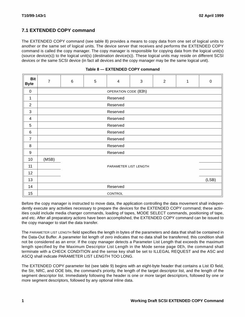
The EXTENDED COPY command (see table 8) provides a means to copy data from one set of logical units toanother or the same set of logical units. The device server that receives and performs the EXTENDED COPYcommand is called the copy manager. The copy manager is responsible for copying data from the logical unit(s)(source device(s)) to the logical unit(s) (destination device(s)). These logical units may reside on different SCSIdevices or the same SCSI device (in fact all devices and the copy manager may be the same logical unit).
Before the copy manager is instructed to move data, the application controlling the data movement shall indepen-dently execute any activities necessary to prepare the devices for the EXTENDED COPY command; these activ-ities could include media changer commands, loading of tapes, MODE SELECT commands, positioning of tape,and etc. After all preparatory actions have been accomplished, the EXTENDED COPY command can be issued tothe copy manager to start the data transfer.
The PARAMETER LIST LENGTH field specifies the length in bytes of the parameters and data that shall be contained inthe Data-Out Buffer. A parameter list length of zero indicates that no data shall be transferred; this condition shallnot be considered as an error. If the copy manager detects a Parameter List Length that exceeds the maximumlength specified by the Maximum Descriptor List Length in the Mode sense page 0Eh, the command shallterminate with a CHECK CONDITION and the sense key shall be set to ILLEGAL REQUEST and the ASC andASCQ shall indicate PARAMETER LIST LENGTH TOO LONG.
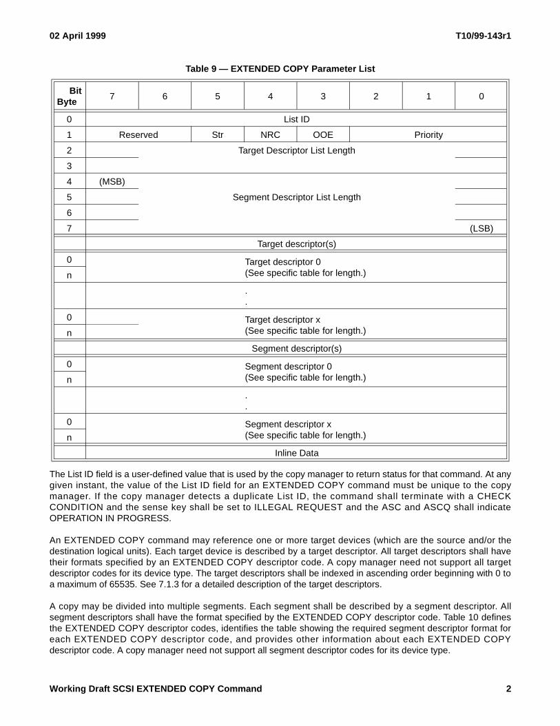
The EXTENDED COPY parameter list (see table 9) begins with an eight-byte header that contains a List ID field,the Str, NRC, and OOE bits, the command’s priority, the length of the target descriptor list, and the length of thesegment descriptor list. Immediately following the header is one or more target descriptors, followed by one ormore segment descriptors, followed by any optional inline data.
Table 8 — EXTENDED COPY command
BitByte
7 6 5 4 3 2 1 0
0 OPERATION CODE (83h)
1 Reserved
2 Reserved
3 Reserved
4 Reserved
5 Reserved
6 Reserved
7 Reserved
8 Reserved
9 Reserved
10 (MSB)
PARAMETER LIST LENGTH11
12
13 (LSB)
14 Reserved
15 CONTROL
1 Working Draft SCSI EXTENDED COPY Command
02 April 1999 T10/99-143r1
The List ID field is a user-defined value that is used by the copy manager to return status for that command. At anygiven instant, the value of the List ID field for an EXTENDED COPY command must be unique to the copymanager. If the copy manager detects a duplicate List ID, the command shall terminate with a CHECKCONDITION and the sense key shall be set to ILLEGAL REQUEST and the ASC and ASCQ shall indicateOPERATION IN PROGRESS.
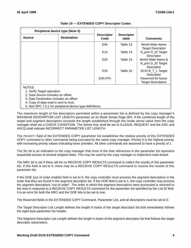
An EXTENDED COPY command may reference one or more target devices (which are the source and/or thedestination logical units). Each target device is described by a target descriptor. All target descriptors shall havetheir formats specified by an EXTENDED COPY descriptor code. A copy manager need not support all targetdescriptor codes for its device type. The target descriptors shall be indexed in ascending order beginning with 0 toa maximum of 65535. See 7.1.3 for a detailed description of the target descriptors.
A copy may be divided into multiple segments. Each segment shall be described by a segment descriptor. Allsegment descriptors shall have the format specified by the EXTENDED COPY descriptor code. Table 10 definesthe EXTENDED COPY descriptor codes, identifies the table showing the required segment descriptor format foreach EXTENDED COPY descriptor code, and provides other information about each EXTENDED COPYdescriptor code. A copy manager need not support all segment descriptor codes for its device type.
Table 9 — EXTENDED COPY Parameter List
BitByte
7 6 5 4 3 2 1 0
0 List ID
1 Reserved Str NRC OOE Priority
2 Target Descriptor List Length
3
4 (MSB)
5 Segment Descriptor List Length
6
7 (LSB)
Target descriptor(s)
0 Target descriptor 0(See specific table for length.)n
.
.
0 Target descriptor x(See specific table for length.)n
Segment descriptor(s)
0 Segment descriptor 0(See specific table for length.)n
.
.
0 Segment descriptor x(See specific table for length.)n
Inline Data
Working Draft SCSI EXTENDED COPY Command 2

T10/99-143r1 02 April 1999
Table 10 — EXTENDED COPY Descriptor Codes
Peripheral device type (Note 5)Descriptor
Code
Descriptor
table CommentsSource Destination
Block devices(Device types 0,4,5,7)Stream devices(Device types 1,3,9)Block devices(Device types 0,4,5,7)Stream devices(Device types 1,3,9)Inline Data
Embedded Data
Stream devices(Device types 1,3,9)Stream or Block device(Device types 0,1,3,4,5,7,9)Block devices(Device types 0,4,5,7)Stream devices(Device types 1,3,9)Block devices(Device types 0,4,5,7)Block devices(Device types 0,4,5,7)Stream devices(Device types 1,3,9)Block devices(Device types 0,4,5,7)Stream devices(Device types 1,3,9)Stream devices(Device types 1,3,9)
Stream devices(Device type 1)
Stream devices(Device types 1,3,9)Block devices(Device types 0,4,5,7)Block devices(Device types 0,4,5,7)Stream devices(Device types 1,2,3,9)Stream devices(Device types 1,3,9)Stream devices(Device types 1,3,9)Discard
Stream devices(Device types 1,3,9)Block devices(Device types 0,4,5,7)Block devices(Device types 0,4,5,7)Stream devices(Device types 1,3,9)Block devices(Device types 0,4,5,7)Block devices(Device types 0,4,5,7)Stream devices(Device types 1,3,9)
Stream devices(Device type 1)Stream devices(Device type 1)Stream devices(Device type 1)Stream devices(Device type 1)
00h
01h
02h
03h
04h
05h
06h
07h
08h
09h
0Ah
0Bh
0Ch
0Dh
0Eh
0Fh
10h
11h
12h
13h
14h-BFh
C0h-DFh
Table 22
Table 22
Table 23
Table 24
Table 25
Table 26
Table 27
Table 28
Table 29
Table 29
Table 30
Table 22
Table 22
Table 23
Table 24
Table 27
Table 31
Table 32
Table 33
Table 34
Note 1
Note 2
Note 3
Note 2&3
Note 4
Note 4
Note 4
Note 4
Note 4
Write Filemarks
Space
Locate
Reserved for Descriptors
Vendor Unique Descriptors
3 Working Draft SCSI EXTENDED COPY Command
02 April 1999 T10/99-143r1
The maximum length of the descriptors permitted within a parameter list is defined by the copy manager’sMAXIMUM DESCRIPTOR LIST LENGTH parameter on its Mode Sense Page 0Eh. If the combined length of thetarget and segment descriptors exceeds the length established through the mode sense value then the copymanager shall set a CHECK CONDITION. The Sense Key shall be set to ILLEGAL REQUEST and the ASC andASCQ shall indicate INCORRECT PARAMETER LIST LENGTH.
The PRIORITY field of the EXTENDED COPY parameter list establishes the relative priority of this EXTENDEDCOPY command to other commands being executed by the same copy manager. Priority 0 is the highest priority,with increasing priority values indicating lower priorities. All other commands are assumed to have a priority of 1.
The Str bit is an indication to the copy manager that most of the disk references in the parameter list representsequential access of several stripped disks. This may be used by the copy manager to implement read-ahead.
The NRC bit is set if there will be no RECEIVE COPY RESULTS command to collect the results of this parameterlist. If this field is set to 0, there may be a RECEIVE COPY RESULTS command to receive the results of thisparameter list.
If the OOE (out of order enable) field is set to 0, the copy controller must process the segment descriptors in theorder that they are found in the segment descriptor list. If the OOE field is set to 1, the copy controller may processthe segment descriptors “out of order”. The order in which the segment descriptors were processed is returned tothe host in response to a RECEIVE COPY RESULTS command for the parameter list specified by the List ID field.It is an error for both the NRC and the OOE bits to be set to one.
The Reserved fields in the EXTENDED COPY Command, Parameter List, and all descriptors must be set to 0.
The Target Descriptor List Length defines the length in bytes of the target descriptor list that immediately followsthe eight-byte parameter list header.
The Segment Descriptor List Length defines the length in bytes of the segment descriptor list that follows the targetdescriptor parameters.
E0h
E1h
E2h
E3h
E4h-FFh
Table 13
Table 14
Table 15
Table 16
World Wide Name Target Descriptor
N_port D_ID Target Descriptor
World Wide Name &N_port D_ID Target
DescriptorSCSI B_T_L Target
DescriptorReserved for future Target Descriptors
NOTES1. Verify Target operation.2. Data Source includes an offset.3. Data Destination includes an offset.4. Copy of data read is sent to host.5. See SPC 7.5.1 for peripheral device type definitions.
Table 10 — EXTENDED COPY Descriptor Codes
Peripheral device type (Note 5)Descriptor
Code
Descriptor
table CommentsSource Destination
Working Draft SCSI EXTENDED COPY Command 4
T10/99-143r1 02 April 1999
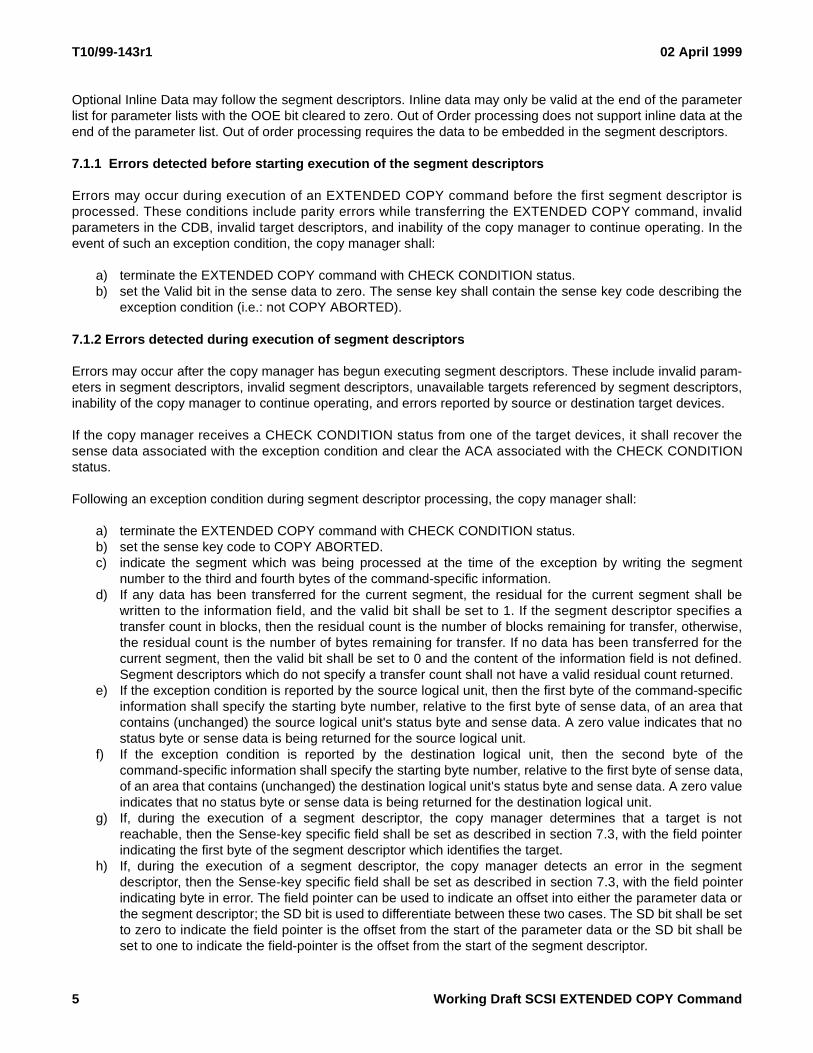
Optional Inline Data may follow the segment descriptors. Inline data may only be valid at the end of the parameterlist for parameter lists with the OOE bit cleared to zero. Out of Order processing does not support inline data at theend of the parameter list. Out of order processing requires the data to be embedded in the segment descriptors.
7.1.1 Errors detected before starting execution of the segment descriptors
Errors may occur during execution of an EXTENDED COPY command before the first segment descriptor isprocessed. These conditions include parity errors while transferring the EXTENDED COPY command, invalidparameters in the CDB, invalid target descriptors, and inability of the copy manager to continue operating. In theevent of such an exception condition, the copy manager shall:
a) terminate the EXTENDED COPY command with CHECK CONDITION status.b) set the Valid bit in the sense data to zero. The sense key shall contain the sense key code describing the
exception condition (i.e.: not COPY ABORTED).
7.1.2 Errors detected during execution of segment descriptors
Errors may occur after the copy manager has begun executing segment descriptors. These include invalid param-eters in segment descriptors, invalid segment descriptors, unavailable targets referenced by segment descriptors,inability of the copy manager to continue operating, and errors reported by source or destination target devices.
If the copy manager receives a CHECK CONDITION status from one of the target devices, it shall recover thesense data associated with the exception condition and clear the ACA associated with the CHECK CONDITIONstatus.
Following an exception condition during segment descriptor processing, the copy manager shall:
a) terminate the EXTENDED COPY command with CHECK CONDITION status.b) set the sense key code to COPY ABORTED.c) indicate the segment which was being processed at the time of the exception by writing the segment
number to the third and fourth bytes of the command-specific information.d) If any data has been transferred for the current segment, the residual for the current segment shall be
written to the information field, and the valid bit shall be set to 1. If the segment descriptor specifies atransfer count in blocks, then the residual count is the number of blocks remaining for transfer, otherwise,the residual count is the number of bytes remaining for transfer. If no data has been transferred for thecurrent segment, then the valid bit shall be set to 0 and the content of the information field is not defined.Segment descriptors which do not specify a transfer count shall not have a valid residual count returned.
e) If the exception condition is reported by the source logical unit, then the first byte of the command-specificinformation shall specify the starting byte number, relative to the first byte of sense data, of an area thatcontains (unchanged) the source logical unit's status byte and sense data. A zero value indicates that nostatus byte or sense data is being returned for the source logical unit.
f) If the exception condition is reported by the destination logical unit, then the second byte of thecommand-specific information shall specify the starting byte number, relative to the first byte of sense data,of an area that contains (unchanged) the destination logical unit's status byte and sense data. A zero valueindicates that no status byte or sense data is being returned for the destination logical unit.
g) If, during the execution of a segment descriptor, the copy manager determines that a target is notreachable, then the Sense-key specific field shall be set as described in section 7.3, with the field pointerindicating the first byte of the segment descriptor which identifies the target.
h) If, during the execution of a segment descriptor, the copy manager detects an error in the segmentdescriptor, then the Sense-key specific field shall be set as described in section 7.3, with the field pointerindicating byte in error. The field pointer can be used to indicate an offset into either the parameter data orthe segment descriptor; the SD bit is used to differentiate between these two cases. The SD bit shall be setto zero to indicate the field pointer is the offset from the start of the parameter data or the SD bit shall beset to one to indicate the field-pointer is the offset from the start of the segment descriptor.
5 Working Draft SCSI EXTENDED COPY Command
02 April 1999 T10/99-143r1
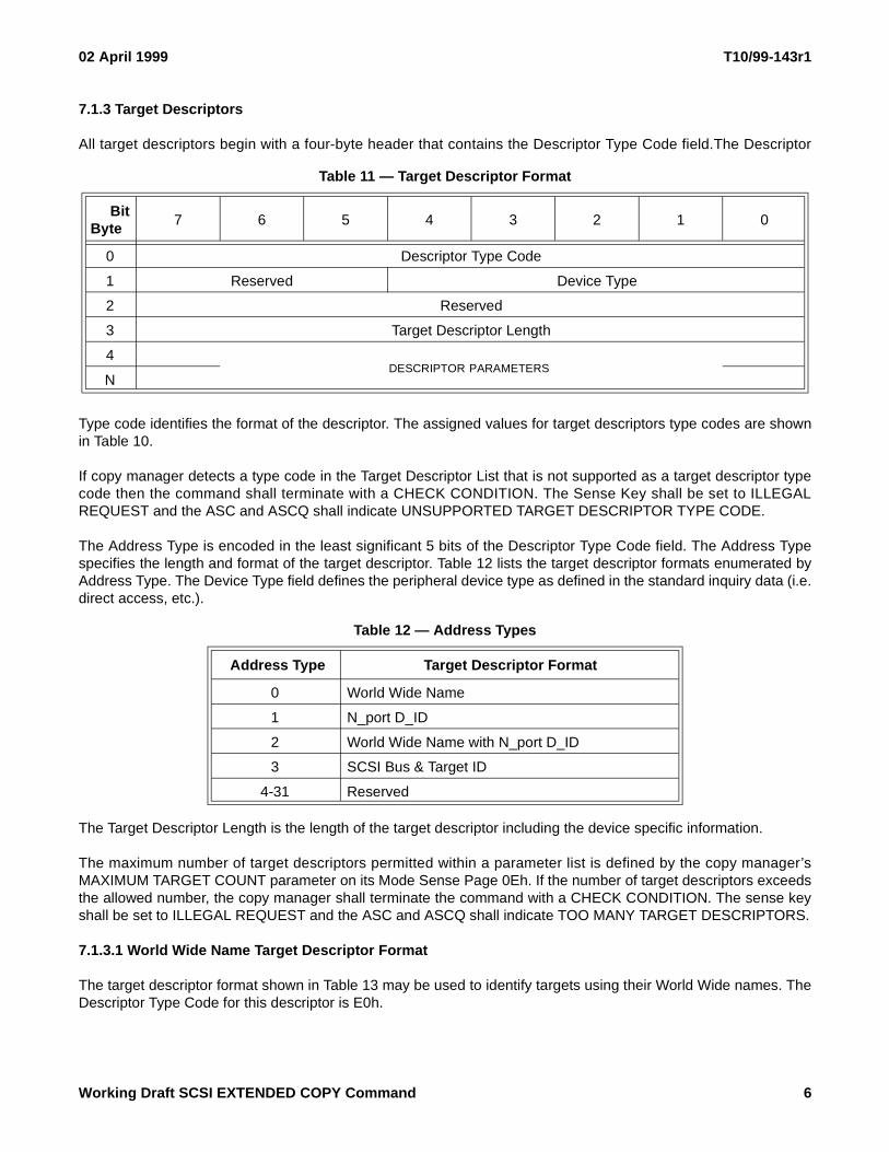
7.1.3 Target Descriptors
All target descriptors begin with a four-byte header that contains the Descriptor Type Code field.The Descriptor
Type code identifies the format of the descriptor. The assigned values for target descriptors type codes are shownin Table 10.
If copy manager detects a type code in the Target Descriptor List that is not supported as a target descriptor typecode then the command shall terminate with a CHECK CONDITION. The Sense Key shall be set to ILLEGALREQUEST and the ASC and ASCQ shall indicate UNSUPPORTED TARGET DESCRIPTOR TYPE CODE.
The Address Type is encoded in the least significant 5 bits of the Descriptor Type Code field. The Address Typespecifies the length and format of the target descriptor. Table 12 lists the target descriptor formats enumerated byAddress Type. The Device Type field defines the peripheral device type as defined in the standard inquiry data (i.e.direct access, etc.).
The Target Descriptor Length is the length of the target descriptor including the device specific information.
The maximum number of target descriptors permitted within a parameter list is defined by the copy manager’sMAXIMUM TARGET COUNT parameter on its Mode Sense Page 0Eh. If the number of target descriptors exceedsthe allowed number, the copy manager shall terminate the command with a CHECK CONDITION. The sense keyshall be set to ILLEGAL REQUEST and the ASC and ASCQ shall indicate TOO MANY TARGET DESCRIPTORS.
7.1.3.1 World Wide Name Target Descriptor Format
The target descriptor format shown in Table 13 may be used to identify targets using their World Wide names. TheDescriptor Type Code for this descriptor is E0h.
Table 11 — Target Descriptor Format
BitByte
7 6 5 4 3 2 1 0
0 Descriptor Type Code
1 Reserved Device Type
2 Reserved
3 Target Descriptor Length
4DESCRIPTOR PARAMETERS
N
Table 12 — Address Types
Address Type Target Descriptor Format
0 World Wide Name
1 N_port D_ID
2 World Wide Name with N_port D_ID
3 SCSI Bus & Target ID
4-31 Reserved
Working Draft SCSI EXTENDED COPY Command 6
T10/99-143r1 02 April 1999
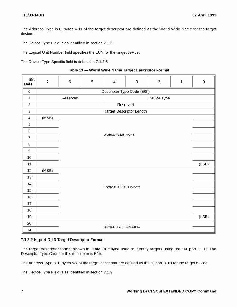
The Address Type is 0, bytes 4-11 of the target descriptor are defined as the World Wide Name for the targetdevice.
The Device Type Field is as identified in section 7.1.3.
The Logical Unit Number field specifies the LUN for the target device.
The Device-Type Specific field is defined in 7.1.3.5.
7.1.3.2 N_port D_ID Target Descriptor Format
The target descriptor format shown in Table 14 maybe used to identify targets using their N_port D_ID. TheDescriptor Type Code for this descriptor is E1h.
The Address Type is 1, bytes 5-7 of the target descriptor are defined as the N_port D_ID for the target device.
The Device Type Field is as identified in section 7.1.3.
Table 13 — World Wide Name Target Descriptor Format
BitByte
7 6 5 4 3 2 1 0
0 Descriptor Type Code (E0h)
1 Reserved Device Type
2 Reserved
3 Target Descriptor Length
4 (MSB)
5
6WORLD WIDE NAME
7
8
9
10
11 (LSB)
12 (MSB)
13
14LOGICAL UNIT NUMBER
15
16
17
18
19 (LSB)
20DEVICE-TYPE SPECIFIC
M
7 Working Draft SCSI EXTENDED COPY Command
02 April 1999 T10/99-143r1
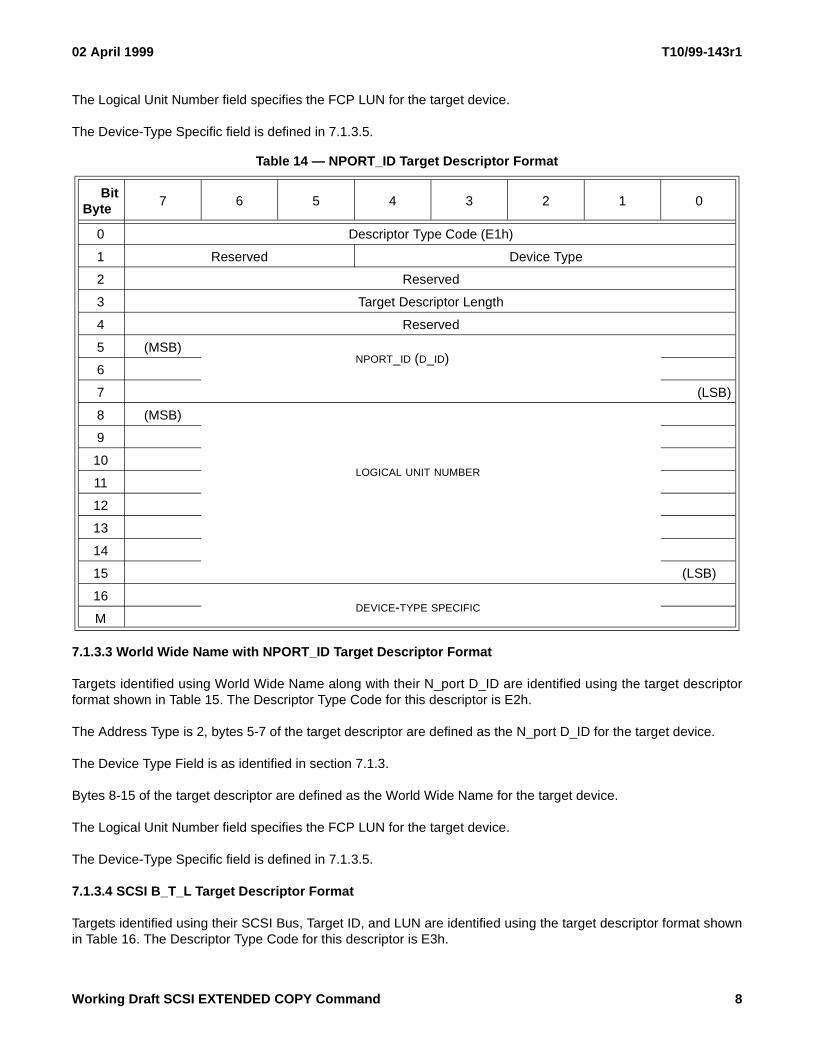
The Logical Unit Number field specifies the FCP LUN for the target device.
The Device-Type Specific field is defined in 7.1.3.5.
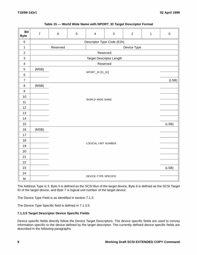
7.1.3.3 World Wide Name with NPORT_ID Target Descriptor Format
Targets identified using World Wide Name along with their N_port D_ID are identified using the target descriptorformat shown in Table 15. The Descriptor Type Code for this descriptor is E2h.
The Address Type is 2, bytes 5-7 of the target descriptor are defined as the N_port D_ID for the target device.
The Device Type Field is as identified in section 7.1.3.
Bytes 8-15 of the target descriptor are defined as the World Wide Name for the target device.
The Logical Unit Number field specifies the FCP LUN for the target device.
The Device-Type Specific field is defined in 7.1.3.5.
7.1.3.4 SCSI B_T_L Target Descriptor Format
Targets identified using their SCSI Bus, Target ID, and LUN are identified using the target descriptor format shownin Table 16. The Descriptor Type Code for this descriptor is E3h.
Table 14 — NPORT_ID Target Descriptor Format
BitByte
7 6 5 4 3 2 1 0
0 Descriptor Type Code (E1h)
1 Reserved Device Type
2 Reserved
3 Target Descriptor Length
4 Reserved
5 (MSB)NPORT_ID (D_ID)
6
7 (LSB)
8 (MSB)
9
10LOGICAL UNIT NUMBER
11
12
13
14
15 (LSB)
16DEVICE-TYPE SPECIFIC
M
Working Draft SCSI EXTENDED COPY Command 8
T10/99-143r1 02 April 1999
The Address Type is 3. Byte 5 is defined as the SCSI Bus of the target device, Byte 6 is defined as the SCSI TargetID of the target device, and Byte 7 is logical unit number of the target device.
The Device Type Field is as identified in section 7.1.3.
The Device-Type Specific field is defined in 7.1.3.5.
7.1.3.5 Target Descriptor Device Specific Fields
Device specific fields directly follow the Device Target Descriptors. The device specific fields are used to conveyinformation specific to the device defined by the target descriptor. The currently defined device specific fields aredescribed in the following paragraphs.
Table 15 — World Wide Name with NPORT_ID Target Descriptor Format
BitByte
7 6 5 4 3 2 1 0
0 Descriptor Type Code (E2h)
1 Reserved Device Type
2 Reserved
3 Target Descriptor Length
4 Reserved
5 (MSB)NPORT_ID (D_ID)
6
7 (LSB)
8 (MSB)
9
10WORLD WIDE NAME
11
12
13
14
15 (LSB)
16 (MSB)
17
18LOGICAL UNIT NUMBER
19
20
21
22
23 (LSB)
24DEVICE-TYPE SPECIFIC
M
9 Working Draft SCSI EXTENDED COPY Command

02 April 1999 T10/99-143r1
The copy manager may, prior to executing a segment descriptor, verify the information in the target descriptor’sdevice specific fields; however, the copy manager shall not issue any commands that change the state of the targetdevice to verify the information.
Device specific information is currently defined for device types 00h and 01h. Device specific information for devicetypes other than 00h and 01h are not yet defined. Until device specific information is defined for these other types,all block devices shall use device specific information of type 00h and all stream devices shall use the devicespecific information of type 01h.
7.1.3.5.1 Device Specific Information for Block Device Types (Type 00h)
Device Specific Information for Block Device Types (Type 00h) is shown in Table 17. The only information requiredfor the block device is the Disk Block Length for the device and the Pad bit. The Disk Block Length is the number ofbytes in a Disk Block for the logical device being addressed. The Pad bit is used in combination with the Cat bit to
control determine the actions on Inexact Segments. The interaction for various combinations of Pad and Cat bits isshown in Table 21.
7.1.3.5.2 Device Specific Information for Stream Device Types (Type 01h)
Device Specific Information for Block Device Types (Type 01h) is shown in Table 18. For stream devices (DeviceType 01h) the Fixed bit and Tape Block Length fields in the Device Specific information are combined with the
Table 16 — SCSI B_T_L Target Descriptor Format
BitByte
7 6 5 4 3 2 1 0
0 Descriptor Type Code (E3h)
1 Reserved Device Type
2 Reserved
3 Target Descriptor Length
4 Reserved
5 SCSI BUS
6 SCSI TARGET ID
7 LOGICAL UNIT NUMBER
8DEVICE-TYPE SPECIFIC
M
Table 17 — Device Specific Field - Device Type 00h
BitByte
7 6 5 4 3 2 1 0
0 Reserved Pad Reserved
1 (MSB)
DISK BLOCK LENGTH2
3 (LSB)
Working Draft SCSI EXTENDED COPY Command 10

T10/99-143r1 02 April 1999
Device Transfer Length field in the segment descriptor to determine the length of the stream data transfer seeTable 19.
The Pad bit is used in combination with the Cat bit to determine the actions on Inexact Segments. The interactionfor various combinations of Pad and Cat bits is shown in Table 21.
The SILI bit indicates the value used in the SILI field of any read command issued to the target.
7.1.4 Segment Descriptors
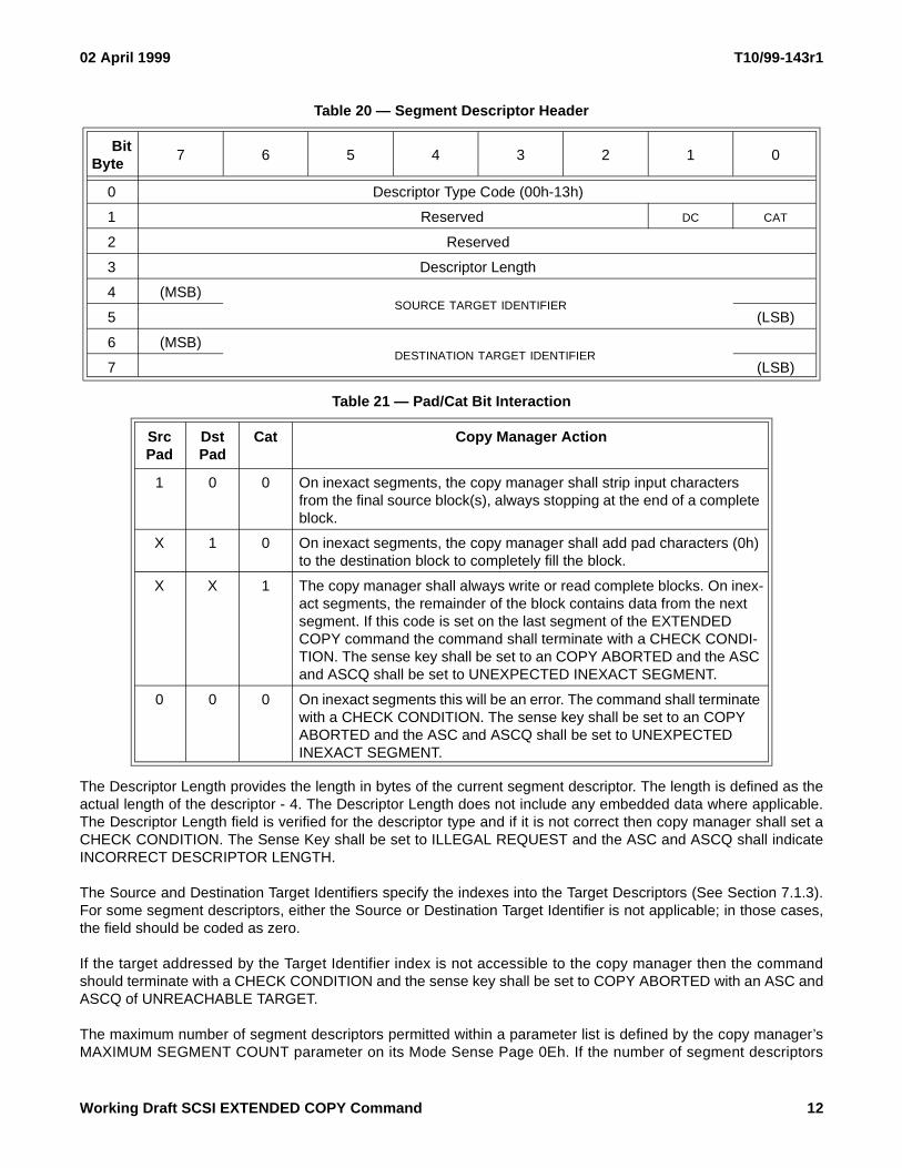
All segment descriptors begin with an eight-byte field as shown in Table 20. The first byte of the segment descriptoris the descriptor type code field which is used to describe the operation for the segment. A list of defined segmentdescriptor type codes can be found in Table 10.
The Destination Count (DC) bit is used with those segment descriptors where the amount of data to be transferredcould be expressed in destination units. The DC bit is only applicable to segment descriptors 02h, 03h, 0Dh, and0Eh; the DC bit is ignored for all other segment descriptors.
The Cat bit is used in conjunction with the Pad bit in the segment descriptors to define what action should be takenwhen a segment of the copy does not fit exactly into an integral number of destination blocks. See Table 21 for adescription on how the Pad and Cat bits interact.
Table 18 — Device Specific Field - Device Type 01h
BitByte
7 6 5 4 3 2 1 0
0 Pad SILI Fixed
1 (MSB)
TAPE BLOCK LENGTH2
3 (LSB)
Table 19 — Tape Transfer Lengths
Fixed Bit Tape Block Length
Meaning
0 0 Use variable length reads/writes. The number bytes for each read/write is specified by the Device Transfer Length field of the segment descriptor.
0 >0 The command shall terminate with a CHECK CONDITION. The Sense Key shall be set to ILLEGAL REQUEST and the ASC and ASCQ shall indicate INVALID FIELD IN PARAMETER LIST.
1 0 The command shall terminate with a CHECK CONDITION. The Sense Key shall be set to ILLEGAL REQUEST and the ASC and ASCQ shall indicate INVALID FIELD IN PARAMETER LIST.
1 >0 Used Fixed Record length reads/writes. The number of bytes for each read/write is the product of the Tape Block Length and the Device Transfer Length field of the segment descriptor.
11 Working Draft SCSI EXTENDED COPY Command
02 April 1999 T10/99-143r1
The Descriptor Length provides the length in bytes of the current segment descriptor. The length is defined as theactual length of the descriptor - 4. The Descriptor Length does not include any embedded data where applicable.The Descriptor Length field is verified for the descriptor type and if it is not correct then copy manager shall set aCHECK CONDITION. The Sense Key shall be set to ILLEGAL REQUEST and the ASC and ASCQ shall indicateINCORRECT DESCRIPTOR LENGTH.
The Source and Destination Target Identifiers specify the indexes into the Target Descriptors (See Section 7.1.3).For some segment descriptors, either the Source or Destination Target Identifier is not applicable; in those cases,the field should be coded as zero.
If the target addressed by the Target Identifier index is not accessible to the copy manager then the commandshould terminate with a CHECK CONDITION and the sense key shall be set to COPY ABORTED with an ASC andASCQ of UNREACHABLE TARGET.
The maximum number of segment descriptors permitted within a parameter list is defined by the copy manager’sMAXIMUM SEGMENT COUNT parameter on its Mode Sense Page 0Eh. If the number of segment descriptors
Table 20 — Segment Descriptor Header
BitByte
7 6 5 4 3 2 1 0
0 Descriptor Type Code (00h-13h)
1 Reserved DC CAT
2 Reserved
3 Descriptor Length
4 (MSB)SOURCE TARGET IDENTIFIER
5 (LSB)
6 (MSB)DESTINATION TARGET IDENTIFIER
7 (LSB)
Table 21 — Pad/Cat Bit Interaction
Src Pad
Dst Pad
Cat Copy Manager Action
1 0 0 On inexact segments, the copy manager shall strip input characters from the final source block(s), always stopping at the end of a complete block.
X 1 0 On inexact segments, the copy manager shall add pad characters (0h) to the destination block to completely fill the block.
X X 1 The copy manager shall always write or read complete blocks. On inex-act segments, the remainder of the block contains data from the next segment. If this code is set on the last segment of the EXTENDED COPY command the command shall terminate with a CHECK CONDI-TION. The sense key shall be set to an COPY ABORTED and the ASC and ASCQ shall be set to UNEXPECTED INEXACT SEGMENT.
0 0 0 On inexact segments this will be an error. The command shall terminate with a CHECK CONDITION. The sense key shall be set to an COPY ABORTED and the ASC and ASCQ shall be set to UNEXPECTED INEXACT SEGMENT.
Working Draft SCSI EXTENDED COPY Command 12
T10/99-143r1 02 April 1999
exceeds the number established through the mode sense value then the copy manager shall set a CHECKCONDITION. The Sense Key shall be set to ILLEGAL REQUEST and the ASC and ASCQ shall indicate TOOMANY SEGMENT DESCRIPTORS.
In general, the specific commands issued by the copy manager to execute the segment descriptors is implemen-tation dependent. Data must be moved from the source devices to the destination devices in a manner that isconsistent with the segment descriptors; the movement must always results in the destination device being at adeterministic state when any intermediate or final status is returned.
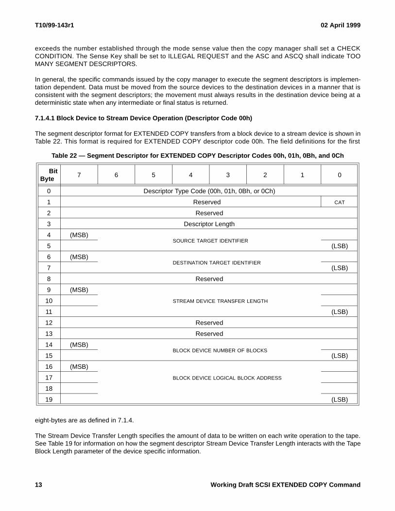
7.1.4.1 Block Device to Stream Device Operation (Descriptor Code 00h)
The segment descriptor format for EXTENDED COPY transfers from a block device to a stream device is shown inTable 22. This format is required for EXTENDED COPY descriptor code 00h. The field definitions for the first
eight-bytes are as defined in 7.1.4.
The Stream Device Transfer Length specifies the amount of data to be written on each write operation to the tape.See Table 19 for information on how the segment descriptor Stream Device Transfer Length interacts with the TapeBlock Length parameter of the device specific information.
Table 22 — Segment Descriptor for EXTENDED COPY Descriptor Codes 00h, 01h, 0Bh, and 0Ch
BitByte
7 6 5 4 3 2 1 0
0 Descriptor Type Code (00h, 01h, 0Bh, or 0Ch)
1 Reserved CAT
2 Reserved
3 Descriptor Length
4 (MSB)SOURCE TARGET IDENTIFIER
5 (LSB)
6 (MSB)DESTINATION TARGET IDENTIFIER
7 (LSB)
8 Reserved
9 (MSB)
STREAM DEVICE TRANSFER LENGTH10
11 (LSB)
12 Reserved
13 Reserved
14 (MSB)BLOCK DEVICE NUMBER OF BLOCKS
15 (LSB)
16 (MSB)
BLOCK DEVICE LOGICAL BLOCK ADDRESS17
18
19 (LSB)
13 Working Draft SCSI EXTENDED COPY Command

02 April 1999 T10/99-143r1
The Block Device Number of Blocks field specifies the number blocks in the current segment to be copied. A valueof zero indicates that no blocks shall be transferred in this segment; this shall not be considered as an error.
The Block Device Logical Block Address field specifies the starting address on the logical unit for this segment.
7.1.4.2 Stream Device to Block Device Operation (Descriptor Code 01h)
The segment descriptor format for EXTENDED COPY transfers from a stream device to a block device is shown inTable 22. This format is required for EXTENDED COPY descriptor code 01h. The field definitions for the firsteight-bytes are as defined in 7.1.4.
The Stream Device Transfer Length specifies the amount of data to be read from the source stream device oneach read operation. See Table 19 for information on how the segment descriptor Stream Device Transfer Lengthinteracts with the Tape Block Length Parameter of the device specific information.
The Block Device Number of Blocks field specifies the number blocks to be copied by the current segment. A valueof zero indicates that no blocks shall be transferred in this segment; this shall not be considered as an error.
The Block Device Logical Block Address field specifies the starting address on the block device for this segmentdescriptor.
7.1.4.3 Block Device to Block Device Operation (Descriptor Code 02h)
The segment descriptor format for EXTENDED COPY transfers between block devices is shown in Table 23. Thisformat is required for EXTENDED COPY descriptor code 02h. The field definitions for the first eight-bytes are asdefined in 7.1.4.
The Block Device Number of Blocks field designates the number of blocks to be transferred from the source blockdevice to the destination block device. A value of zero indicates that no blocks are to be transferred; this shall notbe considered as an error.
The destination count (DC) bit is used to indicate whether the Block Device Number of Blocks field refers to thesource or destination logical unit. A DC bit of zero indicates that the Block Device Number of Blocks field refers tothe source logical unit. A DC bit of one indicates that the Block Device Number of Blocks field refers to the desti-nation logical unit.
The Source Block Device Logical Block Address provides the block address from which the read of data will start.The Destination Block Device Logical Block Address provide the block address at which the write operation willbegin.
7.1.4.4 Stream Device to Stream Device Operation (Descriptor Code 03h)
The segment descriptor format for EXTENDED COPY transfers between two stream devices is shown in Table 24.This format is required for EXTENDED COPY descriptor code 03h. The field definitions for the first eight-bytes areas defined in 7.1.4.
The Source Device Transfer Length specifies the amount of data to be read from the source stream device on eachread operation. See Table 19 for information on how the segment descriptor Source Device Transfer Lengthinteracts with the Tape Block Length Parameter of the device specific information.
Working Draft SCSI EXTENDED COPY Command 14

T10/99-143r1 02 April 1999
The Destination Device Transfer Length specifies the amount of data to be written to the destination stream deviceon each write operation. See Table 19 for information on how the segment descriptor Destination Device TransferLength interacts with the Tape Block Length Parameter of the device specific information.
The Transfer Count field specifies the number of read/write operations that must be executed for this segmentdescriptor. The destination count (DC) bit is used to indicate whether the Transfer Count field refers to the sourceor destination logical unit. A DC bit of zero indicates that the Transfer Count field refers to the source logical unit. ADC bit of one indicates that the Transfer Count field refers to the destination logical unit.
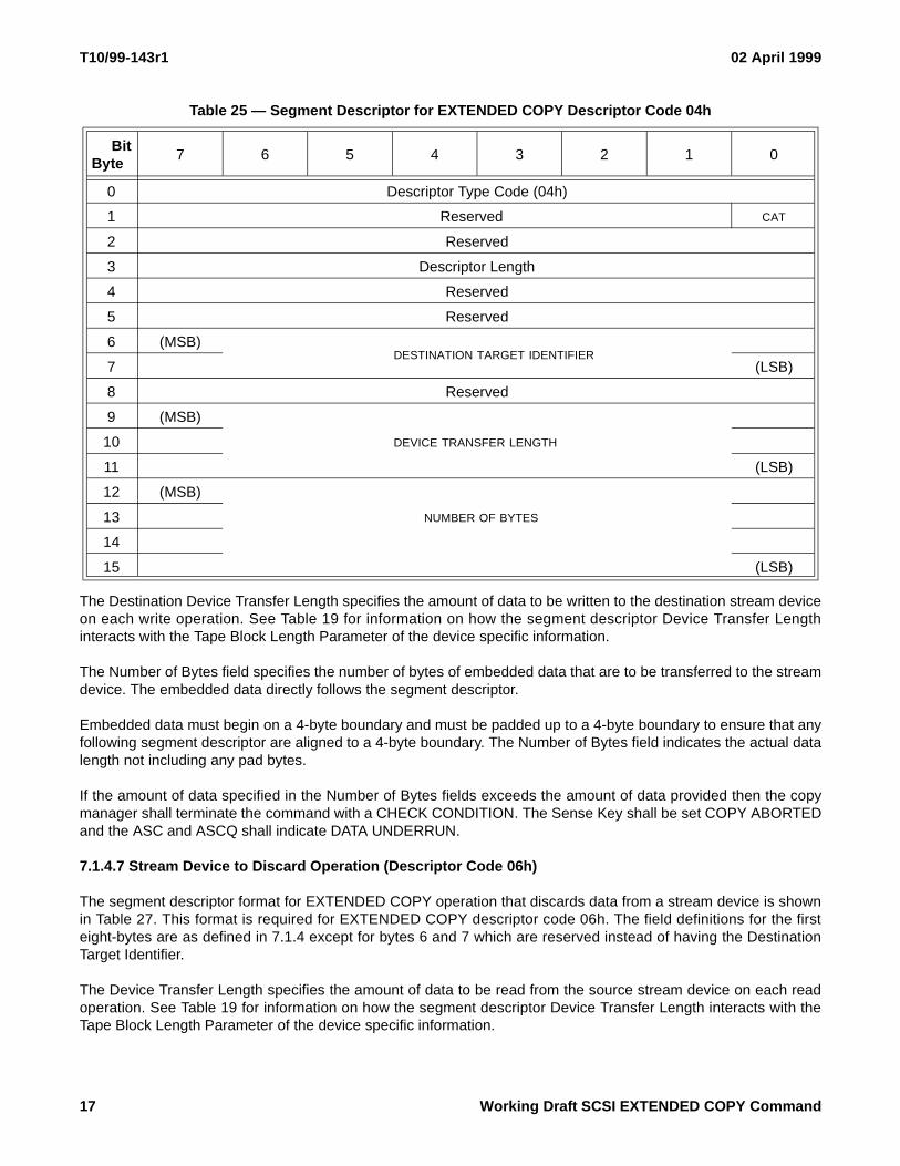
7.1.4.5 Inline Data to Stream Device Operation (Descriptor Code 04h)
The segment descriptor format for EXTENDED COPY operation that moves inline data to a stream device isshown in Table 25. This format is required for EXTENDED COPY descriptor code 04h. The field definitions for thefirst eight-bytes are as defined in 7.1.4 except for bytes 4 and 5 which are reserved instead of having the SourceTarget Identifier.
The Device Transfer Length specifies the amount of data to be written to the destination stream device on eachwrite operation. See Table 19 for information on how the segment descriptor Device Transfer Length interacts withthe Tape Block Length Parameter of the device specific information.
Table 23 — Segment Descriptor for EXTENDED COPY Descriptor Codes 02h and 0Dh
BitByte
7 6 5 4 3 2 1 0
0 Descriptor Type Code (02h or 0Dh)
1 Reserved DC CAT
2 Reserved
3 Descriptor Length
4 (MSB)SOURCE TARGET IDENTIFIER
5 (LSB)
6 (MSB)DESTINATION TARGET IDENTIFIER
7 (LSB)
8 Reserved
9 Reserved
10 (MSB)BLOCK DEVICE NUMBER OF BLOCKS
11 (LSB)
12 (MSB)
SOURCE BLOCK DEVICE LOGICAL BLOCK ADDRESS13
14
15 (LSB)
16 (MSB)
DESTINATION BLOCK DEVICE LOGICAL BLOCK ADDRESS17
18
19 (LSB)
15 Working Draft SCSI EXTENDED COPY Command

02 April 1999 T10/99-143r1
The Number of Bytes field specifies the number of bytes of inline data that are to be transferred to the streamdevice. The inline data comes from the optional inline data at the end of the parameter list. The inline to Streamsegment descriptors must be processed in a sequential manner from first to last to ensure that the inline data at theend of the parameter list is properly assigned.
Inline data must begin on a 4-byte boundary and should be padded up to a 4-byte boundary. The Number of Bytesfield indicates the actual data length not including any pad bytes.
If the amount of data specified in the Number of Bytes fields exceeds the amount of data provided then the copymanager shall terminate the command with a CHECK CONDITION. The Sense Key shall be set COPY ABORTEDand the ASC and ASCQ shall indicate DATA UNDERRUN.
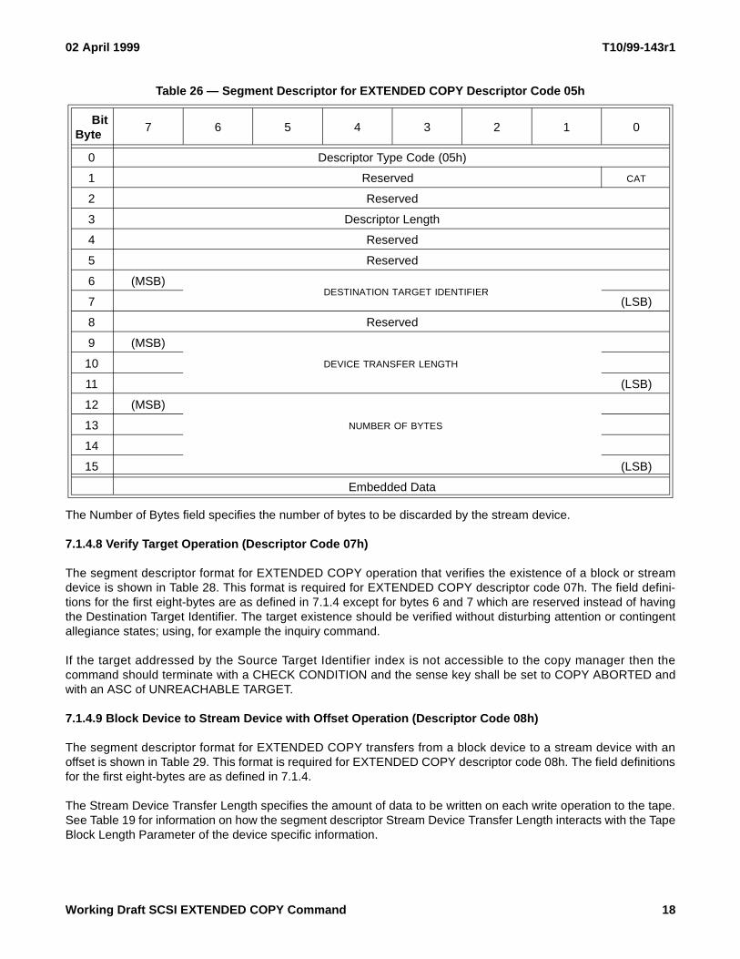
7.1.4.6 Embedded Data to Stream Device Operation (Descriptor Code 05h)
The segment descriptor format for EXTENDED COPY operation that moves embedded data to a stream device isshown in Table 26. This format is required for EXTENDED COPY descriptor code 05h. The field definitions for thefirst eight-bytes are as defined in 7.1.4 except for bytes 4 and 5 which are reserved instead of having the SourceTarget Identifier.
Table 24 — Segment Descriptor for EXTENDED COPY Descriptor Codes 03h and 0Eh
BitByte
7 6 5 4 3 2 1 0
0 Descriptor Type Code (03h or 0Eh)
1 Reserved DC CAT
2 Reserved
3 Descriptor Length
4 (MSB)SOURCE TARGET IDENTIFIER
5 (LSB)
6 (MSB)DESTINATION TARGET IDENTIFIER
7 (LSB)
8 Reserved
9 (MSB)
SOURCE DEVICE TRANSFER LENGTH10
11 (LSB)
12 Reserved
13 (MSB)
DESTINATION DEVICE TRANSFER LENGTH14
15 (LSB)
16 (MSB)
TRANSFER COUNT17
18
19 (LSB)
Working Draft SCSI EXTENDED COPY Command 16
T10/99-143r1 02 April 1999
The Destination Device Transfer Length specifies the amount of data to be written to the destination stream deviceon each write operation. See Table 19 for information on how the segment descriptor Device Transfer Lengthinteracts with the Tape Block Length Parameter of the device specific information.
The Number of Bytes field specifies the number of bytes of embedded data that are to be transferred to the streamdevice. The embedded data directly follows the segment descriptor.
Embedded data must begin on a 4-byte boundary and must be padded up to a 4-byte boundary to ensure that anyfollowing segment descriptor are aligned to a 4-byte boundary. The Number of Bytes field indicates the actual datalength not including any pad bytes.
If the amount of data specified in the Number of Bytes fields exceeds the amount of data provided then the copymanager shall terminate the command with a CHECK CONDITION. The Sense Key shall be set COPY ABORTEDand the ASC and ASCQ shall indicate DATA UNDERRUN.
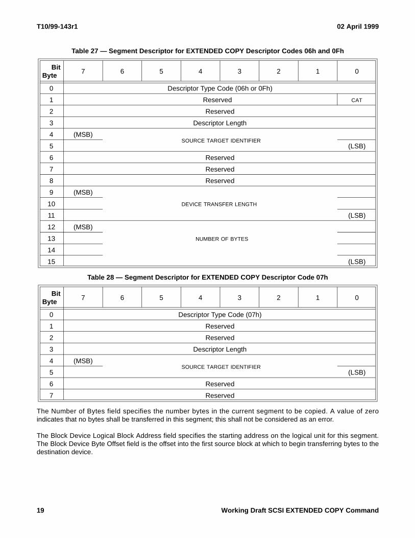
7.1.4.7 Stream Device to Discard Operation (Descriptor Code 06h)
The segment descriptor format for EXTENDED COPY operation that discards data from a stream device is shownin Table 27. This format is required for EXTENDED COPY descriptor code 06h. The field definitions for the firsteight-bytes are as defined in 7.1.4 except for bytes 6 and 7 which are reserved instead of having the DestinationTarget Identifier.
The Device Transfer Length specifies the amount of data to be read from the source stream device on each readoperation. See Table 19 for information on how the segment descriptor Device Transfer Length interacts with theTape Block Length Parameter of the device specific information.
Table 25 — Segment Descriptor for EXTENDED COPY Descriptor Code 04h
BitByte
7 6 5 4 3 2 1 0
0 Descriptor Type Code (04h)
1 Reserved CAT
2 Reserved
3 Descriptor Length
4 Reserved
5 Reserved
6 (MSB)DESTINATION TARGET IDENTIFIER
7 (LSB)
8 Reserved
9 (MSB)
DEVICE TRANSFER LENGTH10
11 (LSB)
12 (MSB)
NUMBER OF BYTES13
14
15 (LSB)
17 Working Draft SCSI EXTENDED COPY Command
02 April 1999 T10/99-143r1
The Number of Bytes field specifies the number of bytes to be discarded by the stream device.
7.1.4.8 Verify Target Operation (Descriptor Code 07h)
The segment descriptor format for EXTENDED COPY operation that verifies the existence of a block or streamdevice is shown in Table 28. This format is required for EXTENDED COPY descriptor code 07h. The field defini-tions for the first eight-bytes are as defined in 7.1.4 except for bytes 6 and 7 which are reserved instead of havingthe Destination Target Identifier. The target existence should be verified without disturbing attention or contingentallegiance states; using, for example the inquiry command.
If the target addressed by the Source Target Identifier index is not accessible to the copy manager then thecommand should terminate with a CHECK CONDITION and the sense key shall be set to COPY ABORTED andwith an ASC of UNREACHABLE TARGET.
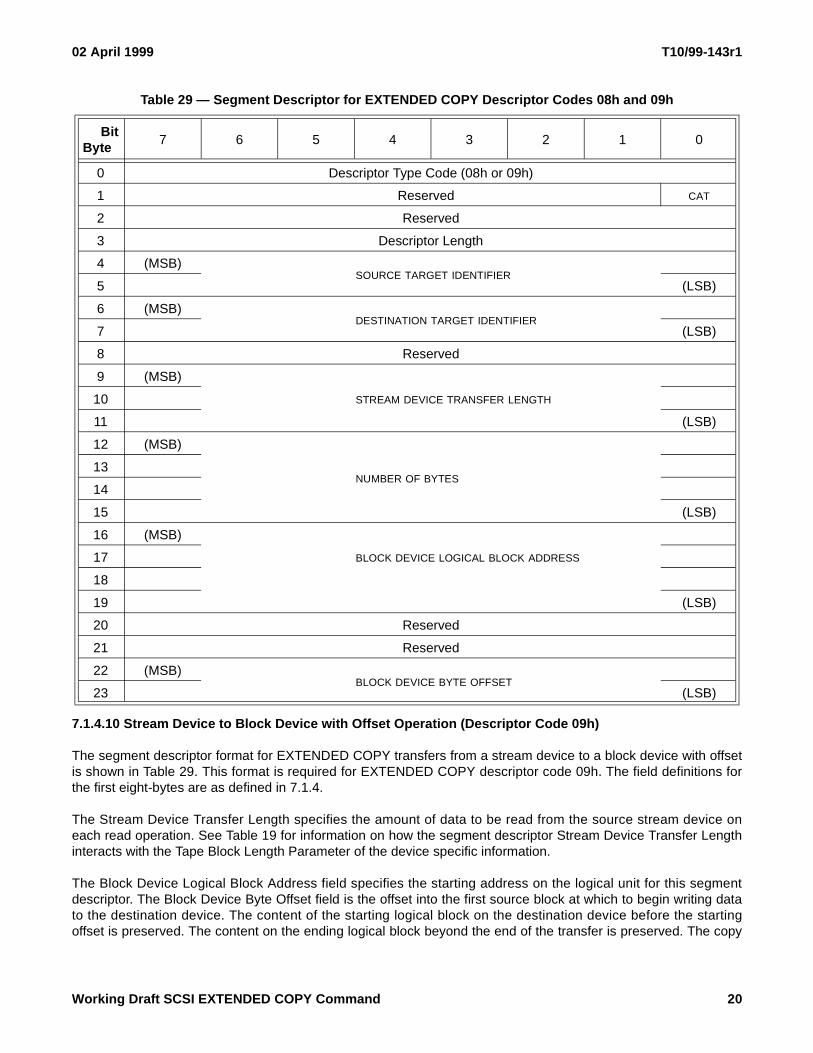
7.1.4.9 Block Device to Stream Device with Offset Operation (Descriptor Code 08h)
The segment descriptor format for EXTENDED COPY transfers from a block device to a stream device with anoffset is shown in Table 29. This format is required for EXTENDED COPY descriptor code 08h. The field definitionsfor the first eight-bytes are as defined in 7.1.4.
The Stream Device Transfer Length specifies the amount of data to be written on each write operation to the tape.See Table 19 for information on how the segment descriptor Stream Device Transfer Length interacts with the TapeBlock Length Parameter of the device specific information.
Table 26 — Segment Descriptor for EXTENDED COPY Descriptor Code 05h
BitByte
7 6 5 4 3 2 1 0
0 Descriptor Type Code (05h)
1 Reserved CAT
2 Reserved
3 Descriptor Length
4 Reserved
5 Reserved
6 (MSB)DESTINATION TARGET IDENTIFIER
7 (LSB)
8 Reserved
9 (MSB)
DEVICE TRANSFER LENGTH10
11 (LSB)
12 (MSB)
NUMBER OF BYTES13
14
15 (LSB)
Embedded Data
Working Draft SCSI EXTENDED COPY Command 18
T10/99-143r1 02 April 1999
The Number of Bytes field specifies the number bytes in the current segment to be copied. A value of zeroindicates that no bytes shall be transferred in this segment; this shall not be considered as an error.
The Block Device Logical Block Address field specifies the starting address on the logical unit for this segment.The Block Device Byte Offset field is the offset into the first source block at which to begin transferring bytes to thedestination device.
Table 27 — Segment Descriptor for EXTENDED COPY Descriptor Codes 06h and 0Fh
BitByte
7 6 5 4 3 2 1 0
0 Descriptor Type Code (06h or 0Fh)
1 Reserved CAT
2 Reserved
3 Descriptor Length
4 (MSB)SOURCE TARGET IDENTIFIER
5 (LSB)
6 Reserved
7 Reserved
8 Reserved
9 (MSB)
DEVICE TRANSFER LENGTH10
11 (LSB)
12 (MSB)
NUMBER OF BYTES13
14
15 (LSB)
Table 28 — Segment Descriptor for EXTENDED COPY Descriptor Code 07h
BitByte
7 6 5 4 3 2 1 0
0 Descriptor Type Code (07h)
1 Reserved
2 Reserved
3 Descriptor Length
4 (MSB)SOURCE TARGET IDENTIFIER
5 (LSB)
6 Reserved
7 Reserved
19 Working Draft SCSI EXTENDED COPY Command
02 April 1999 T10/99-143r1
7.1.4.10 Stream Device to Block Device with Offset Operation (Descriptor Code 09h)
The segment descriptor format for EXTENDED COPY transfers from a stream device to a block device with offsetis shown in Table 29. This format is required for EXTENDED COPY descriptor code 09h. The field definitions forthe first eight-bytes are as defined in 7.1.4.
The Stream Device Transfer Length specifies the amount of data to be read from the source stream device oneach read operation. See Table 19 for information on how the segment descriptor Stream Device Transfer Lengthinteracts with the Tape Block Length Parameter of the device specific information.
The Block Device Logical Block Address field specifies the starting address on the logical unit for this segmentdescriptor. The Block Device Byte Offset field is the offset into the first source block at which to begin writing datato the destination device. The content of the starting logical block on the destination device before the startingoffset is preserved. The content on the ending logical block beyond the end of the transfer is preserved. The copy
Table 29 — Segment Descriptor for EXTENDED COPY Descriptor Codes 08h and 09h
BitByte
7 6 5 4 3 2 1 0
0 Descriptor Type Code (08h or 09h)
1 Reserved CAT
2 Reserved
3 Descriptor Length
4 (MSB)SOURCE TARGET IDENTIFIER
5 (LSB)
6 (MSB)DESTINATION TARGET IDENTIFIER
7 (LSB)
8 Reserved
9 (MSB)
STREAM DEVICE TRANSFER LENGTH10
11 (LSB)
12 (MSB)
NUMBER OF BYTES13
14
15 (LSB)
16 (MSB)
BLOCK DEVICE LOGICAL BLOCK ADDRESS17
18
19 (LSB)
20 Reserved
21 Reserved
22 (MSB)BLOCK DEVICE BYTE OFFSET
23 (LSB)
Working Draft SCSI EXTENDED COPY Command 20

T10/99-143r1 02 April 1999
manager may implement this operation by reading in the starting and ending logical blocks, modifying the portionof the blocks as required, and writing the full blocks to the destination.
7.1.4.11 Block Device to Block Device with Offsets Operation (Descriptor Code 0Ah)
The segment descriptor format for EXTENDED COPY transfers between block devices with an offset is shown inTable 30. This format is required for EXTENDED COPY descriptor code 0Ah. The field definitions for the first
eight-bytes are as defined in 7.1.4.
The Number of Bytes field specifies the number bytes in the current segment to be copied. A value of zeroindicates that no bytes shall be transferred in this segment; this shall not be considered as an error.
Table 30 — Segment Descriptor for EXTENDED COPY Descriptor Code 0Ah
BitByte
7 6 5 4 3 2 1 0
0 Descriptor Type Code (0Ah)
1 Reserved
2 Reserved
3 Descriptor Length
4 (MSB)SOURCE TARGET IDENTIFIER
5 (LSB)
6 (MSB)DESTINATION TARGET IDENTIFIER
7 (LSB)
8 (MSB)
NUMBER OF BYTES9
10
11 (LSB)
12 (MSB)
SOURCE BLOCK DEVICE LOGICAL BLOCK ADDRESS13
14
15 (LSB)
16 (MSB)
DESTINATION BLOCK DEVICE LOGICAL BLOCK ADDRESS17
18
19 (LSB)
20 (MSB)SOURCE BLOCK DEVICE BYTE OFFSET
21 (LSB)
22 (MSB)DESTINATION BLOCK DEVICE BYTE OFFSET
23 (LSB)
21 Working Draft SCSI EXTENDED COPY Command

02 April 1999 T10/99-143r1
The Source Block Device Logical Block Address provides the block address from which the read of data will start.The Destination Block Device Logical Block Address provide the block address at which the write operation willbegin. The Source and Destination Block Device Byte Offsets contain the offsets into the first source and desti-nation block at which to begin transferring data. The content of the starting logical block on the destination devicebefore the starting offset is preserved. The content on the ending logical block beyond the end of the transfer ispreserved. The copy manager may implement this operation by reading in the starting and ending logical blocks,modifying the portion of the blocks as required, and writing the full blocks to the destination.
7.1.4.12 Block Device to Stream Device with Copy to Host Operation (Descriptor Code 0Bh)
The segment descriptor format for EXTENDED COPY transfers from a block device to a stream device with a copyto the host is shown in Table 22. The format required for this operation is the same as that for the EXTENDEDCOPY descriptor code 00h, the only difference is that the descriptor code in byte 0 is a 0Bh. Functionally the onlydifference between the segment descriptors 00h and 0Bh is that the 0Bh segment descriptor forwards a copy of thedata read from the block device to the host that requested the EXTENDED COPY operation. The data read fromthe block device will be transferred to the host using the RECEIVE COPY RESULTS command.
7.1.4.13 Stream Device to Block Device with Copy to Host Operation (Descriptor Code 0Ch)
The segment descriptor format for EXTENDED COPY transfers from a block device to a stream device with a copyto the host is shown in Table 22. The format required for this operation is the same as that for the EXTENDEDCOPY descriptor code 01h, the only difference is that the descriptor code in byte 0 is a 0Ch. Functionally the onlydifference between the segment descriptors 01h and 0Ch is that the 0Ch segment descriptor forwards a copy ofthe data read from the stream device to the host that requested the EXTENDED COPY operation. The data readfrom the stream device will be transferred to the host using the RECEIVE COPY RESULTS command.
7.1.4.14 Block Device to Block Device with Copy to Host Operation (Descriptor Code 0Dh)
The segment descriptor format for EXTENDED COPY transfers from a block device to a block device with a copyto the host is shown in Table 23. The format required for this operation is the same as that for the EXTENDEDCOPY descriptor code 02h, the only difference is that the descriptor code in byte 0 is a 0Dh. Functionally the onlydifference between the segment descriptors 02h and 0Dh is that the 0Dh segment descriptor forwards a copy ofthe data read from the block device to the host that requested the EXTENDED COPY operation. The data readfrom the block device will be transferred to the host using the RECEIVE COPY RESULTS command.
7.1.4.15 Stream Device to Stream Device with Copy to Host Operation (Descriptor Code 0Eh)
The segment descriptor format for EXTENDED COPY transfers from a stream device to a stream device with acopy to the host is shown in Table 24. The format required for this operation is the same as that for the EXTENDEDCOPY descriptor code 03h, the only difference is that the descriptor code in byte 0 is a 0Eh. Functionally the onlydifference between the segment descriptors 03h and 0Eh is that the 0Eh segment descriptor forwards a copy of thedata read from the stream device to the host that requested the EXTENDED COPY operation. The data read fromthe stream device will be transferred to the host using the RECEIVE COPY RESULTS command.
7.1.4.16 Stream Device to Host Operation (Descriptor Code 0Fh)
The segment descriptor format for EXTENDED COPY transfer from a stream device to a host is shown in Table 27.This format is required for EXTENDED COPY descriptor code 0Fh. The field definitions for the first eight-bytes areas defined in 7.1.4 except that bytes 6 and 7 are reserved and no destination device is specified.
The Stream Device Transfer Length designates the amount of data to be transferred from source stream device tothe host. See Table 19 for information on how segment descriptor Stream Device Transfer Length interacts with theTape Block Length parameter of the device specific information.
Working Draft SCSI EXTENDED COPY Command 22
T10/99-143r1 02 April 1999
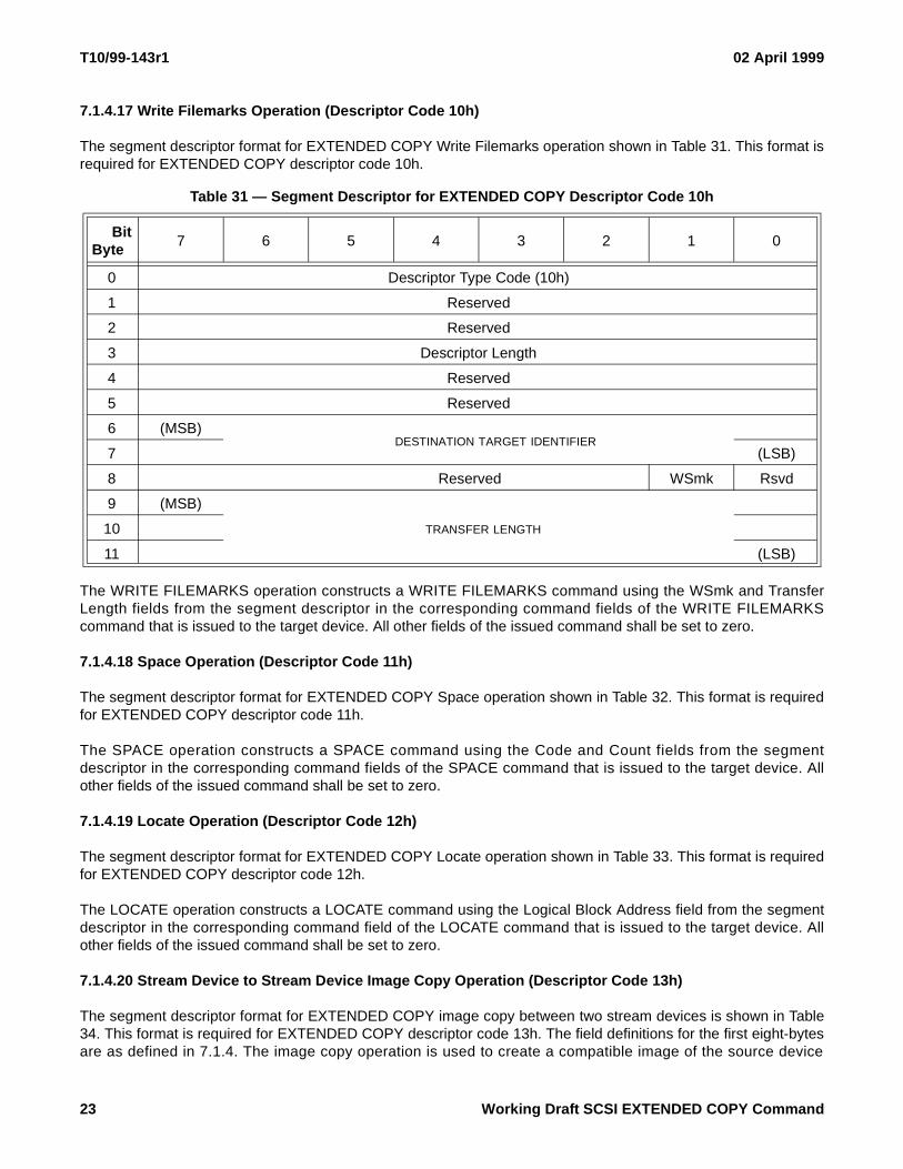
7.1.4.17 Write Filemarks Operation (Descriptor Code 10h)
The segment descriptor format for EXTENDED COPY Write Filemarks operation shown in Table 31. This format isrequired for EXTENDED COPY descriptor code 10h.
The WRITE FILEMARKS operation constructs a WRITE FILEMARKS command using the WSmk and TransferLength fields from the segment descriptor in the corresponding command fields of the WRITE FILEMARKScommand that is issued to the target device. All other fields of the issued command shall be set to zero.
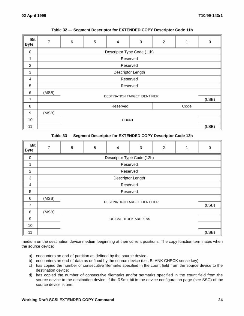
7.1.4.18 Space Operation (Descriptor Code 11h)
The segment descriptor format for EXTENDED COPY Space operation shown in Table 32. This format is requiredfor EXTENDED COPY descriptor code 11h.
The SPACE operation constructs a SPACE command using the Code and Count fields from the segmentdescriptor in the corresponding command fields of the SPACE command that is issued to the target device. Allother fields of the issued command shall be set to zero.
7.1.4.19 Locate Operation (Descriptor Code 12h)
The segment descriptor format for EXTENDED COPY Locate operation shown in Table 33. This format is requiredfor EXTENDED COPY descriptor code 12h.
The LOCATE operation constructs a LOCATE command using the Logical Block Address field from the segmentdescriptor in the corresponding command field of the LOCATE command that is issued to the target device. Allother fields of the issued command shall be set to zero.
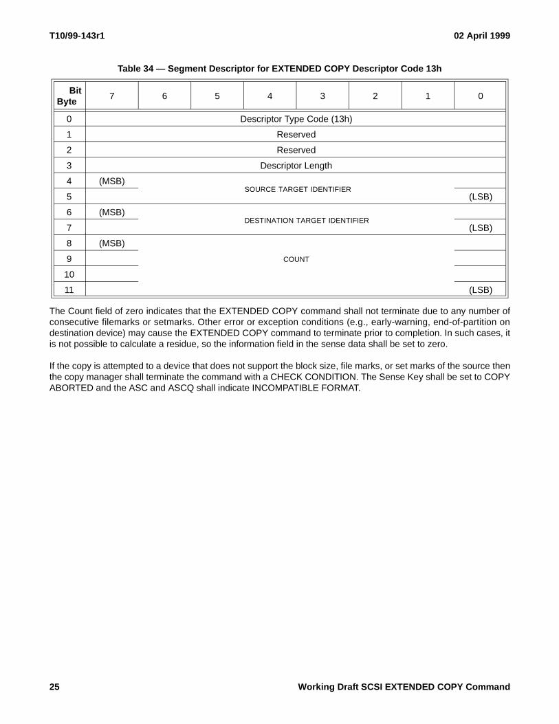
7.1.4.20 Stream Device to Stream Device Image Copy Operation (Descriptor Code 13h)
The segment descriptor format for EXTENDED COPY image copy between two stream devices is shown in Table34. This format is required for EXTENDED COPY descriptor code 13h. The field definitions for the first eight-bytesare as defined in 7.1.4. The image copy operation is used to create a compatible image of the source device
Table 31 — Segment Descriptor for EXTENDED COPY Descriptor Code 10h
BitByte
7 6 5 4 3 2 1 0
0 Descriptor Type Code (10h)
1 Reserved
2 Reserved
3 Descriptor Length
4 Reserved
5 Reserved
6 (MSB)DESTINATION TARGET IDENTIFIER
7 (LSB)
8 Reserved WSmk Rsvd
9 (MSB)
TRANSFER LENGTH10
11 (LSB)
23 Working Draft SCSI EXTENDED COPY Command
02 April 1999 T10/99-143r1
medium on the destination device medium beginning at their current positions. The copy function terminates whenthe source device:
a) encounters an end-of-partition as defined by the source device;b) encounters an end-of-data as defined by the source device (i.e., BLANK CHECK sense key);c) has copied the number of consecutive filemarks specified in the count field from the source device to the
destination device;d) has copied the number of consecutive filemarks and/or setmarks specified in the count field from the
source device to the destination device, if the RSmk bit in the device configuration page (see SSC) of thesource device is one.
Table 32 — Segment Descriptor for EXTENDED COPY Descriptor Code 11h
BitByte
7 6 5 4 3 2 1 0
0 Descriptor Type Code (11h)
1 Reserved
2 Reserved
3 Descriptor Length
4 Reserved
5 Reserved
6 (MSB)DESTINATION TARGET IDENTIFIER
7 (LSB)
8 Reserved Code
9 (MSB)
COUNT10
11 (LSB)
Table 33 — Segment Descriptor for EXTENDED COPY Descriptor Code 12h
BitByte
7 6 5 4 3 2 1 0
0 Descriptor Type Code (12h)
1 Reserved
2 Reserved
3 Descriptor Length
4 Reserved
5 Reserved
6 (MSB)DESTINATION TARGET IDENTIFIER
7 (LSB)
8 (MSB)
LOGICAL BLOCK ADDRESS9
10
11 (LSB)
Working Draft SCSI EXTENDED COPY Command 24
T10/99-143r1 02 April 1999
The Count field of zero indicates that the EXTENDED COPY command shall not terminate due to any number ofconsecutive filemarks or setmarks. Other error or exception conditions (e.g., early-warning, end-of-partition ondestination device) may cause the EXTENDED COPY command to terminate prior to completion. In such cases, itis not possible to calculate a residue, so the information field in the sense data shall be set to zero.
If the copy is attempted to a device that does not support the block size, file marks, or set marks of the source thenthe copy manager shall terminate the command with a CHECK CONDITION. The Sense Key shall be set to COPYABORTED and the ASC and ASCQ shall indicate INCOMPATIBLE FORMAT.
Table 34 — Segment Descriptor for EXTENDED COPY Descriptor Code 13h
BitByte
7 6 5 4 3 2 1 0
0 Descriptor Type Code (13h)
1 Reserved
2 Reserved
3 Descriptor Length
4 (MSB)SOURCE TARGET IDENTIFIER
5 (LSB)
6 (MSB)DESTINATION TARGET IDENTIFIER
7 (LSB)
8 (MSB)
COUNT9
10
11 (LSB)
25 Working Draft SCSI EXTENDED COPY Command

02 April 1999 T10/99-143r1
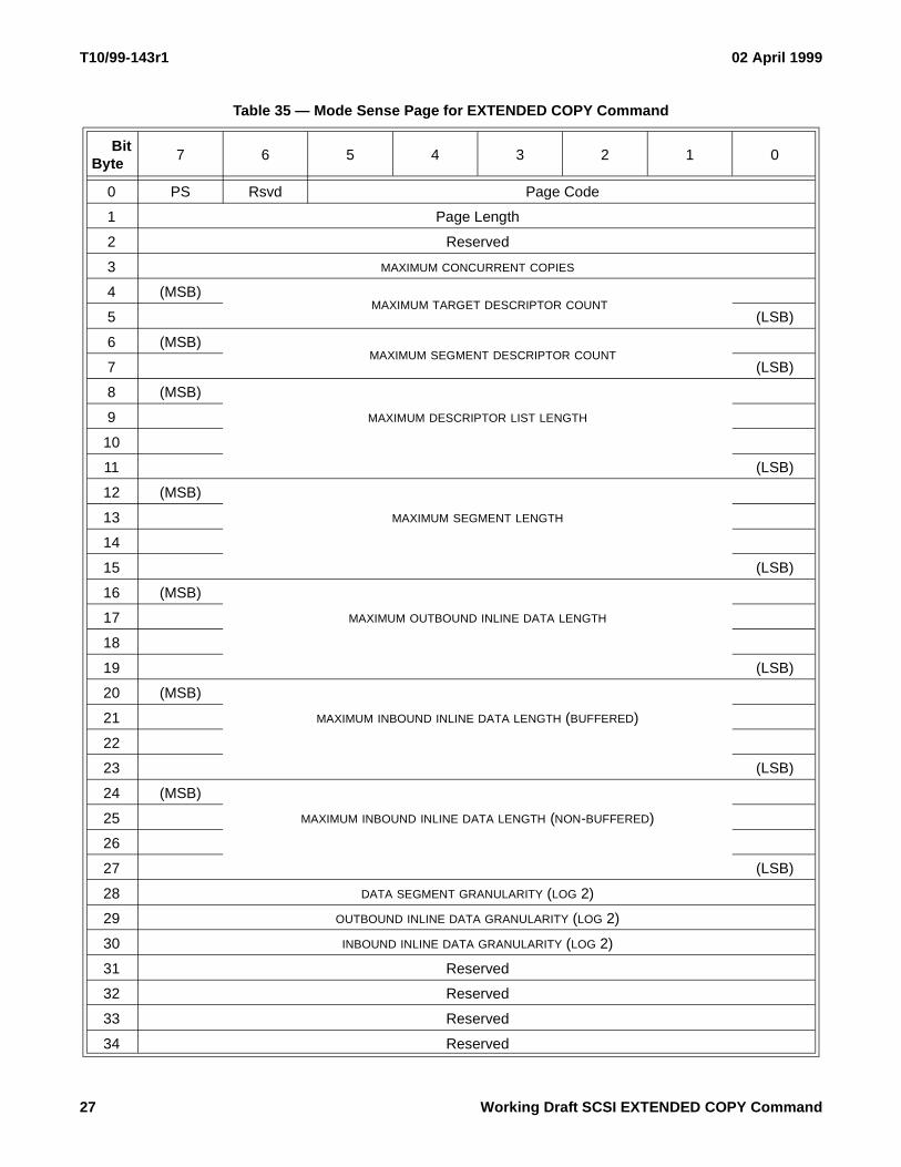
7.2 Mode Sense Page for EXTENDED COPY Command
Mode sense information pertaining to the operation of the EXTENDED COPY command’s copy manager isobtained from the copy manager using the 0Eh Mode Sense Page shown in Table 35.
The PS (Page Savable) field is always set to 0 to indicate that this page is not savable.
The Page Length field provides the length in bytes of the remainder of the mode sense page. The Page Length isthe actual length of the Mode Sense Page - 2.
The Maximum Concurrent Copies is the maximum number of EXTENDED COPY CDBs that the copy manager canbe executing at a single instant of time.
The Maximum Target Count is the maximum number of target descriptors that the copy manager allows in a singleEXTENDED COPY target descriptor list.
The Maximum Segment Count is the maximum number of segment descriptors that the copy manager allows in asingle EXTENDED COPY segment descriptor list.
The Maximum Descriptor List Length field is the maximum length, in bytes, of the target descriptor list and segmentdescriptor list; this length includes the embedded data but excludes inline data that follows the parameter list.
The Maximum Segment Length indicates the length, in bytes, of the largest amount of data that can be specified ina single segment.
The Maximum Outbound Inline Data Length indicates the length, in bytes, of the largest amount of inline data thatcan be included after the EXTENDED COPY parameter list; this does not include data included as embedded datawithin the segment descriptors. The Maximum Outbound Inline Data Length applies only to the 04h segmentdescriptor and shall be set to zero when the 04h segment descriptor is not supported.
The Maximum Inbound Inline Data Length (Buffered Implementation) indicates the length, in bytes, of the largestamount of inline data to be buffered by the copy manager and returned to the host.
The Maximum Inbound Inline Data Length (non-Buffered Implementation) indicates the length, in bytes, of thelargest amount of inline data to be returned to a host but not buffered by the copy manager; this implies the abilityto have an outstanding RECEIVE COPY RESULTS concurrent with the EXTENDED COPY command.
The Data Segment Granularity indicates the length of the smallest block that a non-inline segment descriptor candescribe. The amount of data transferred by a single segment descriptor must be a multiple of the granularity. TheData Segment Granularity is expressed as a power of 2.
The Outbound Inline Data Granularity indicates the length of the of the smallest block of inline data that can betransferred from the host to the copy manager. The amount of data transferred by a single segment descriptor mustbe a multiple of the granularity. The Outbound Inline Data Granularity is expressed as a power of 2.
The Inbound Inline Data Granularity indicates the length of the smallest block of inline data that can be transferredto the host from the copy manager. The amount of data transferred by a single segment descriptor must be amultiple of the granularity. The Inbound Inline Data Granularity is expressed as a power of 2.
The Implemented Descriptor List Length is the length, in bytes, of the Descriptor Length field.
The Descriptor List is a list of one byte descriptor types that are supported by the copy manager. The descriptor listshall be ordered in ascending order
Working Draft SCSI EXTENDED COPY Command 26
T10/99-143r1 02 April 1999
Table 35 — Mode Sense Page for EXTENDED COPY Command
BitByte
7 6 5 4 3 2 1 0
0 PS Rsvd Page Code
1 Page Length
2 Reserved
3 MAXIMUM CONCURRENT COPIES
4 (MSB)MAXIMUM TARGET DESCRIPTOR COUNT
5 (LSB)
6 (MSB) MAXIMUM SEGMENT DESCRIPTOR COUNT
7 (LSB)
8 (MSB)
MAXIMUM DESCRIPTOR LIST LENGTH9
10
11 (LSB)
12 (MSB)
MAXIMUM SEGMENT LENGTH13
14
15 (LSB)
16 (MSB)
MAXIMUM OUTBOUND INLINE DATA LENGTH17
18
19 (LSB)
20 (MSB)
MAXIMUM INBOUND INLINE DATA LENGTH (BUFFERED)21
22
23 (LSB)
24 (MSB)
MAXIMUM INBOUND INLINE DATA LENGTH (NON-BUFFERED)25
26
27 (LSB)
28 DATA SEGMENT GRANULARITY (LOG 2)
29 OUTBOUND INLINE DATA GRANULARITY (LOG 2)
30 INBOUND INLINE DATA GRANULARITY (LOG 2)
31 Reserved
32 Reserved
33 Reserved
34 Reserved
27 Working Draft SCSI EXTENDED COPY Command

02 April 1999 T10/99-143r1
35 IMPLEMENTED DESCRIPTOR LIST LENGTH
36 Ordered list of Implemented Descriptors
33+n
Table 35 — Mode Sense Page for EXTENDED COPY Command
BitByte
7 6 5 4 3 2 1 0
Working Draft SCSI EXTENDED COPY Command 28
T10/99-143r1 02 April 1999
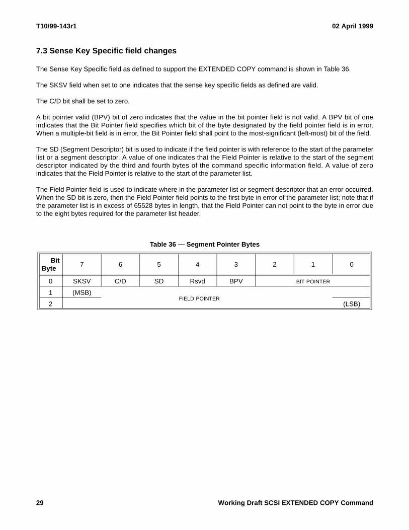
7.3 Sense Key Specific field changes
The Sense Key Specific field as defined to support the EXTENDED COPY command is shown in Table 36.
The SKSV field when set to one indicates that the sense key specific fields as defined are valid.
The C/D bit shall be set to zero.
A bit pointer valid (BPV) bit of zero indicates that the value in the bit pointer field is not valid. A BPV bit of oneindicates that the Bit Pointer field specifies which bit of the byte designated by the field pointer field is in error.When a multiple-bit field is in error, the Bit Pointer field shall point to the most-significant (left-most) bit of the field.
The SD (Segment Descriptor) bit is used to indicate if the field pointer is with reference to the start of the parameterlist or a segment descriptor. A value of one indicates that the Field Pointer is relative to the start of the segmentdescriptor indicated by the third and fourth bytes of the command specific information field. A value of zeroindicates that the Field Pointer is relative to the start of the parameter list.
The Field Pointer field is used to indicate where in the parameter list or segment descriptor that an error occurred.When the SD bit is zero, then the Field Pointer field points to the first byte in error of the parameter list; note that ifthe parameter list is in excess of 65528 bytes in length, that the Field Pointer can not point to the byte in error dueto the eight bytes required for the parameter list header.
Table 36 — Segment Pointer Bytes
BitByte
7 6 5 4 3 2 1 0
0 SKSV C/D SD Rsvd BPV BIT POINTER
1 (MSB)FIELD POINTER
2 (LSB)
29 Working Draft SCSI EXTENDED COPY Command

02 April 1999 T10/99-143r1
7.4 RECEIVE COPY RESULTS Command
The RECEIVE COPY RESULTS command is used to return the results of a previous (or current) EXTENDEDCOPY command. The results that can be returned from the previous (or current) EXTENDED COPY command areeither copy manager status information, inline data from read operations, or information about the order in whichthe segments were processed during the EXTENDED COPY command. The CDB used for the RECEIVE COPYRESULTS command is shown in Table 37.
The Mode field is used to define the type of RECEIVE COPY RESULTS operation to be executed. Table 38provides definitions for the values that can be used for the Mode field. If an invalid Mode Value is specified, then
Table 37 — RECEIVE COPY RESULTS Command
BitByte
7 6 5 4 3 2 1 0
0 OPERATION CODE (84h)
1 Reserved Mode
2 List ID
3 Reserved
4 Reserved
5 Reserved
6 Reserved
7 Reserved
8 Reserved
9 Reserved
10 (MSB)
ALLOCATION LENGTH11
12
13 (LSB)
14 Reserved
15 CONTROL
Table 38 — Mode Field Definitions
Mode Value
RECEIVE COPY RESULTS Operation
0 Return the current Copy Status of the executing EXTENDED COPY command identified by List ID.
1 Return the Inline data read by EXTENDED COPY com-mand identified by List ID.
2 Return the Segment Order List that identifies the order in which the segments where written to the destination device during the EXTENDED COPY command identi-fied by List ID.
3-7 Reserved.
Working Draft SCSI EXTENDED COPY Command 30

T10/99-143r1 02 April 1999
the copy manager shall terminate the command with a CHECK CONDITION. The Sense Key shall be set toILLEGAL REQUEST and the ASC and ASCQ shall indicate INVALID FIELD IN CDB.
The RECEIVE COPY RESULTS command will return information from the EXTENDED COPY command origi-nated from the same Initiator with a List ID which matches the List ID specified in the RECEIVE COPY RESULTSCDB. If no EXTENDED COPY command corresponds to the List ID, then the command will complete with CHECKCONDITION status and the ASC and ASCQ shall indicate INVALID FIELD IN CDB.
If the EXTENDED COPY command is active and the Mode field has a value of 1 (Inline Data) or 2 (SegmentOrder), the copy manager shall wait for the completion of that active EXTENDED COPY command. Otherwise, ifthe EXTENDED COPY command has completed, or it the Mode field has a value of 0 (Copy Status), the copymanager shall return data and status immediately.
Inline data which is held by the copy manager following completion of an EXTENDED COPY command will bepreserved for a reasonable period of time by the copy manager. The application should issue a RECEIVE COPYRESULTS command immediately following completion of the EXTENDED COPY command to insure that the datais not discarded by the copy manager. The copy manager will discard the buffered inline data after it has beensuccessfully transferred to the host; when a RECIEVE COPY RESULTS command is issued by the same host forthe same List ID, with mode set to 1 (Inline Data) with the allocation length set to 0; when another EXTENDEDCOPY command is issued by the same host using the same List ID; when the copy manager is reset; or when thecopy manager requires the resources used to preserve the data.
If an EXTENDED COPY command is issued with Out of Order Enable (OOE) set to 1, then the copy manager willhold a copy of the Segment Order List. The Segment Order List which is held by the copy manager followingcompletion of an EXTENDED COPY command will be preserved for a reasonable period of time by the copymanager. The application should issue a RECEIVE COPY RESULTS command immediately following completionof the EXTENDED COPY command to insure that the data is not discarded by the copy manager. The copymanager will discard the Segment Order List after it has been successfully transferred to the host; when aRECIEVE COPY RESULTS command is issued by the same host for the same List ID, with mode set to 2(Segment Order List) with the allocation length set to 0; when another EXTENDED COPY command is issued bythe same host using the same List ID; when the copy manager is reset; or when the copy manager requires theresources used to preserve the data.
The completion status of an EXTENDED COPY command will be preserved by the copy manager for a reasonableperiod of time. The copy manager will discard the completion status when a RECIEVE COPY RESULTS commandis issued by the same host for the same List ID, with mode set to 0 (Copy Status); when another EXTENDEDCOPY command is issued by the same host using the same List ID; when the copy manager is reset; or when thecopy manager requires the resources used to preserve the data.
The Allocation Length field should specify a value large enough to contain the results of the RECEIVE COPYRESULTS command.
7.4.1 Copy Status Mode
When the Mode field is set to return copy results, the copy manager returns the current status of the EXTENDEDCOPY command identified by the List ID field. Table 40 shows the format of the information returned by the copymanager in response to a request for Copy Status.
The Status field is the current status of the copy manager. Valid status values that the manager can report in theStatus field are shown in Table 39.
The Segment Number field is the number of the segment descriptor (zero based) that is currently executing on thecopy manager. This field shall be zero if the copy manager has not yet begun executing segment descriptors.
31 Working Draft SCSI EXTENDED COPY Command

02 April 1999 T10/99-143r1
The Transfer Count Format field specifies the format of the transfer count. The Transfer Count Format is coded asshown in Table 41.
The Transfer Count field specifies the amount of data transferred by the EXTENDED COPY command prior toreceiving the request for copy status.
7.4.2 Receive Data Mode
If the copy manager supports those segment descriptors that transfer copied data to the host, then setting theMode field to the Receive Data Results value causes the copy manager to return any read data using the formatshown in Table 42.
The Data Available field is the length of the inline data that follows the Data Available field. The Inline Data field isthe data that was read by the copy manager.
Table 39 — Copy Manager Status Codes
Status Code
Definition
0 OPERATION IN PROGRESS
1 COPY COMPLETED
2 COPY TERMINATED WITH ERRORS
Table 40 — Return Data Format - Mode 0 (Status)
BitByte
7 6 5 4 3 2 1 0
0 STATUS
1 (MSB)SEGMENT NUMBER
2 (LSB)
3 Transfer Count Format
4 (MSB)
TRANSFER COUNT5
6
7 (LSB)
Table 41 — Transfer Count Format
Transfer Count Format Value
Transfer Count Format
0 bytes
1 Kilobytes
2 MegaBytes
3 Gigabytes
4 Terabytes
5 Petabytes
Working Draft SCSI EXTENDED COPY Command 32
T10/99-143r1 02 April 1999
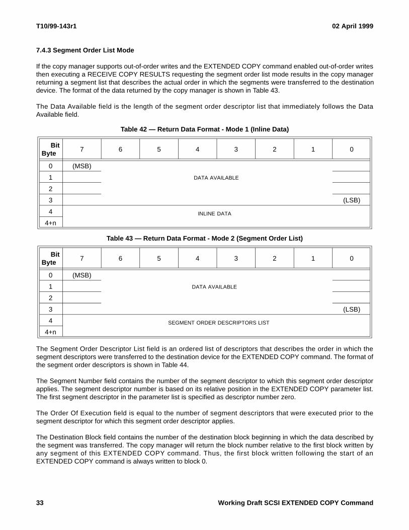
7.4.3 Segment Order List Mode
If the copy manager supports out-of-order writes and the EXTENDED COPY command enabled out-of-order writesthen executing a RECEIVE COPY RESULTS requesting the segment order list mode results in the copy managerreturning a segment list that describes the actual order in which the segments were transferred to the destinationdevice. The format of the data returned by the copy manager is shown in Table 43.
The Data Available field is the length of the segment order descriptor list that immediately follows the DataAvailable field.
The Segment Order Descriptor List field is an ordered list of descriptors that describes the order in which thesegment descriptors were transferred to the destination device for the EXTENDED COPY command. The format ofthe segment order descriptors is shown in Table 44.
The Segment Number field contains the number of the segment descriptor to which this segment order descriptorapplies. The segment descriptor number is based on its relative position in the EXTENDED COPY parameter list.The first segment descriptor in the parameter list is specified as descriptor number zero.
The Order Of Execution field is equal to the number of segment descriptors that were executed prior to thesegment descriptor for which this segment order descriptor applies.
The Destination Block field contains the number of the destination block beginning in which the data described bythe segment was transferred. The copy manager will return the block number relative to the first block written byany segment of this EXTENDED COPY command. Thus, the first block written following the start of anEXTENDED COPY command is always written to block 0.
Table 42 — Return Data Format - Mode 1 (Inline Data)
BitByte
7 6 5 4 3 2 1 0
0 (MSB)
DATA AVAILABLE1
2
3 (LSB)
4 INLINE DATA
4+n
Table 43 — Return Data Format - Mode 2 (Segment Order List)
BitByte
7 6 5 4 3 2 1 0
0 (MSB)
DATA AVAILABLE1
2
3 (LSB)
4 SEGMENT ORDER DESCRIPTORS LIST
4+n
33 Working Draft SCSI EXTENDED COPY Command

02 April 1999 T10/99-143r1
The destination offset field contains the offset, in bytes, into that block beginning at which the data described by thesegment was transferred.
Table 44 — Segment Order Descriptor
BitByte
7 6 5 4 3 2 1 0
0 (MSB)SEGMENT NUMBER
1 (LSB)
2 (MSB)ORDER OF EXECUTION
3 (LSB)
4 (MSB)
DESTINATION BLOCK5
6
7 (LSB)
8 (MSB)
DESTINATION OFFSET9
10
11 (LSB)
Working Draft SCSI EXTENDED COPY Command 34


![arXiv:2006.10509v1 [cs.GR] 18 Jun 2020 · 2020. 6. 19. · IOption - Base parameter interface extended by all parameter types. Extends INode. Command - Abstract base command class](https://img.pdfslide.net/doc/110x75/6099f0c8dd31ba27472bb139/arxiv200610509v1-csgr-18-jun-2020-2020-6-19-ioption-base-parameter-interface.jpg)


![Evidence-based Extended Response Writing Prompts … EBW prompts 2015[2] copy... · Evidence-based Extended Response Writing Prompts ... Evidence-based Extended Response Writing Prompts](https://img.pdfslide.net/doc/110x75/5a8c80e67f8b9a4a268c96b9/evidence-based-extended-response-writing-prompts-ebw-prompts-20152-copyevidence-based.jpg)