Embed Size (px)
Citation preview
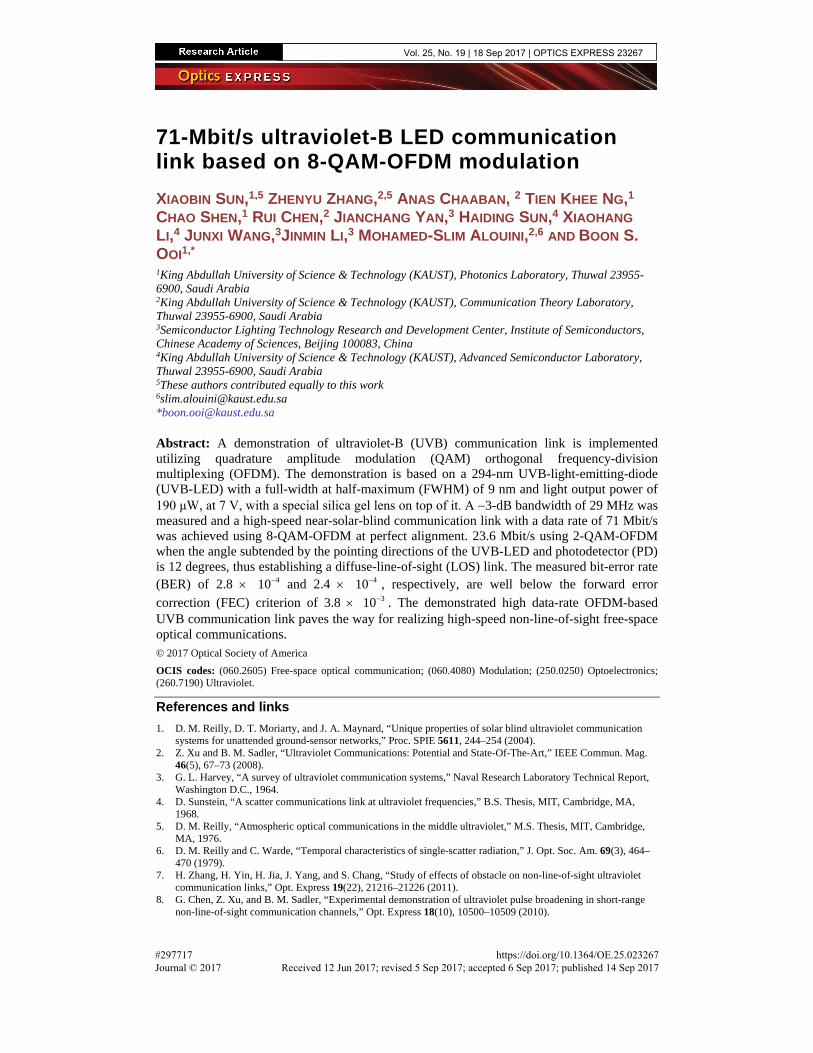
71-Mbit/s ultraviolet-B LED communication link based on 8-QAM-OFDM modulation XIAOBIN SUN,1,5 ZHENYU ZHANG,2,5 ANAS CHAABAN, 2 TIEN KHEE NG,1 CHAO SHEN,1 RUI CHEN,2 JIANCHANG YAN,3 HAIDING SUN,4 XIAOHANG LI,4 JUNXI WANG,3JINMIN LI,3 MOHAMED-SLIM ALOUINI,2,6 AND BOON S. OOI1,* 1King Abdullah University of Science & Technology (KAUST), Photonics Laboratory, Thuwal 23955-6900, Saudi Arabia 2King Abdullah University of Science & Technology (KAUST), Communication Theory Laboratory, Thuwal 23955-6900, Saudi Arabia 3Semiconductor Lighting Technology Research and Development Center, Institute of Semiconductors, Chinese Academy of Sciences, Beijing 100083, China 4King Abdullah University of Science & Technology (KAUST), Advanced Semiconductor Laboratory, Thuwal 23955-6900, Saudi Arabia 5These authors contributed equally to this work [email protected] *[email protected]
Abstract: A demonstration of ultraviolet-B (UVB) communication link is implemented utilizing quadrature amplitude modulation (QAM) orthogonal frequency-division multiplexing (OFDM). The demonstration is based on a 294-nm UVB-light-emitting-diode (UVB-LED) with a full-width at half-maximum (FWHM) of 9 nm and light output power of 190 μW, at 7 V, with a special silica gel lens on top of it. A −3-dB bandwidth of 29 MHz was measured and a high-speed near-solar-blind communication link with a data rate of 71 Mbit/s was achieved using 8-QAM-OFDM at perfect alignment. 23.6 Mbit/s using 2-QAM-OFDM when the angle subtended by the pointing directions of the UVB-LED and photodetector (PD) is 12 degrees, thus establishing a diffuse-line-of-sight (LOS) link. The measured bit-error rate (BER) of 2.8 × 410− and 2.4 × 410− , respectively, are well below the forward error correction (FEC) criterion of 3.8 × 310− . The demonstrated high data-rate OFDM-based UVB communication link paves the way for realizing high-speed non-line-of-sight free-space optical communications. © 2017 Optical Society of America OCIS codes: (060.2605) Free-space optical communication; (060.4080) Modulation; (250.0250) Optoelectronics; (260.7190) Ultraviolet.
References and links 1. D. M. Reilly, D. T. Moriarty, and J. A. Maynard, “Unique properties of solar blind ultraviolet communication
systems for unattended ground-sensor networks,” Proc. SPIE 5611, 244–254 (2004). 2. Z. Xu and B. M. Sadler, “Ultraviolet Communications: Potential and State-Of-The-Art,” IEEE Commun. Mag.
46(5), 67–73 (2008). 3. G. L. Harvey, “A survey of ultraviolet communication systems,” Naval Research Laboratory Technical Report,
Washington D.C., 1964. 4. D. Sunstein, “A scatter communications link at ultraviolet frequencies,” B.S. Thesis, MIT, Cambridge, MA,
1968. 5. D. M. Reilly, “Atmospheric optical communications in the middle ultraviolet,” M.S. Thesis, MIT, Cambridge,
MA, 1976. 6. D. M. Reilly and C. Warde, “Temporal characteristics of single-scatter radiation,” J. Opt. Soc. Am. 69(3), 464–
470 (1979). 7. H. Zhang, H. Yin, H. Jia, J. Yang, and S. Chang, “Study of effects of obstacle on non-line-of-sight ultraviolet
communication links,” Opt. Express 19(22), 21216–21226 (2011). 8. G. Chen, Z. Xu, and B. M. Sadler, “Experimental demonstration of ultraviolet pulse broadening in short-range
non-line-of-sight communication channels,” Opt. Express 18(10), 10500–10509 (2010).
Vol. 25, No. 19 | 18 Sep 2017 | OPTICS EXPRESS 23267
#297717 Journal © 2017
https://doi.org/10.1364/OE.25.023267 Received 12 Jun 2017; revised 5 Sep 2017; accepted 6 Sep 2017; published 14 Sep 2017

9. L. C. Liao, Z. N. Li, T. Lang, B. M. Sadler, and G. Chen, “Turbulence channel test and analysis for NLOS UV communication,” Proc. SPIE 9224, 92241A (2014).
10. R. J. Drost, T. Lang, G. Chen, L. Liao, Z. Li, and B. M. Sadler, “Long-distance non-line-of-sight ultraviolet communication channel analysis: experimentation and modelling,” IET Optoelectron. 9(5), 223–231 (2015).
11. T. Feng, F. Xiong, Q. Ye, Z. Q. Pan, Z. R. Dong, and Z. J. Fang, “Non-line-of-sight optical scattering communication based on solar-blind ultraviolet light,” Proc. SPIE 6783, 67833X (2007).
12. B. Charles, B. Hughes, A. Erickson, J. Wilkins, and E. A. Teppo, “Ultraviolet-laser based communication-system for short-range tactical application,” Proc. SPIE 2115, 79–86 (1994).
13. C. Lee, C. Shen, H. M. Oubei, M. Cantore, B. Janjua, T. K. Ng, R. M. Farrell, M. M. El-Desouki, J. S. Speck, S. Nakamura, B. S. Ooi, and S. P. DenBaars, “2 Gbit/s data transmission from an unfiltered laser-based phosphor-converted white lighting communication system,” Opt. Express 23(23), 29779–29787 (2015).
14. C. Shen, T. K. Ng, J. T. Leonard, A. Pourhashemi, H. M. Oubei, M. S. Alias, S. Nakamura, S. P. DenBaars, J. S. Speck, A. Y. Alyamani, M. M. Eldesouki, and B. S. Ooi, “High-Modulation-Efficiency, Integrated Waveguide Modulator-Laser Diode at 448 nm,” ACS Photonics 3(2), 262–268 (2016).
15. D. Tsonev, S. Videv, and H. Haas, “Towards a 100 Gb/s visible light wireless access network,” Opt. Express 23(2), 1627–1637 (2015).
16. B. Janjua, H. M. Oubei, J. R. D. Retamal, T. K. Ng, C.-T. Tsai, H.-Y. Wang, Y.-C. Chi, H.-C. Kuo, G.-R. Lin, J.-H. He, and B. S. Ooi, “Going beyond 4 Gbps data rate by employing RGB laser diodes for visible light communication,” Opt. Express 23(14), 18746–18753 (2015).
17. C. Shen, C. Lee, T. K. Ng, S. Nakamura, J. S. Speck, S. P. DenBaars, A. Y. Alyamani, M. M. El-Desouki, and B. S. Ooi, “High-speed 405-nm superluminescent diode (SLD) with 807-MHz modulation bandwidth,” Opt. Express 24(18), 20281–20286 (2016).
18. D. Kedar and S. Arnon, “Non-line-of-sight optical wireless sensor network operating in multiscattering channel,” Appl. Opt. 45(33), 8454–8461 (2006).
19. D. Kedar and S. Arnon, “Subsea ultraviolet solar-blind broadband free-space optics communication,” Opt. Eng. 48(4), 046001 (2009).
20. C. Lavigne, G. Durand, and A. Roblin, “Ultraviolet light propagation under low visibility atmospheric conditions and its application to aircraft landing aid,” Appl. Opt. 45(36), 9140–9150 (2006).
21. C. Lavigne, G. Durand, and A. Roblin, “Simulation comparison of aircraft landing performance in foggy conditions aided by different UV sensors,” Appl. Opt. 48(12), 2203–2213 (2009).
22. S. Arnon and D. Kedar, “Non-line-of-sight underwater optical wireless communication network,” J. Opt. Soc. Am. A 26(3), 530–539 (2009).
23. G. A. Shaw, A. M. Siegel, and J. Model, “Extending the range and performance of non-line-of-sight ultraviolet communication links,” Proc. SPIE 6231, 62310C (2006).
24. C. Lavigne, G. Durand, and A. Roblin, “Ultraviolet light propagation under low visibility atmospheric conditions and its application to aircraft landing aid,” Appl. Opt. 45(36), 9140–9150 (2006).
25. B. Charles, B. Hughes, A. Erickson, J. Wilkins, and E. Teppo, “An ultraviolet laser based communication system for short range tactical applications,” Proc. SPIE 2115, 79–86 (1994).
26. G. Chen, F. Abou-Galala, Z. Xu, and B. M. Sadler, “Experimental evaluation of LED-based solar blind NLOS communication links,” Opt. Express 16(19), 15059–15068 (2008).
27. N. Raptis, E. Pikasis, and D. Syvridis, “Power losses in diffuse ultraviolet optical communications channels,” Opt. Lett. 41(18), 4421–4424 (2016).
28. D. Han, Y. Liu, K. Zhang, P. Luo, and M. Zhang, “Theoretical and experimental research on diversity reception technology in NLOS UV communication system,” Opt. Express 20(14), 15833–15842 (2012).
29. J. J. Puschell and R. Bayse, “High data rate ultraviolet communication systems for the tactical battlefield,” Proc. of Tactical Communications Conf., 253–267 (1990).
30. M. Geller, et, “Optical Non-Line- of-Sight Covert, Secure High-Data Communication System,” Nava Ocean Systems Center, San Diego, California, U. S. Patent Number 4,493,114, (1985).
31. J. Yan, J. Wang, Y. Zhang, P. Cong, L. Sun, Y. Tian, C. Zhao, and J. Li, “AlGaN-based deep-ultraviolet light-emitting diodes grown on high-quality AlN template using MOVPE,” J. Cryst. Growth 414, 254–257 (2015).
1. Introduction Communication systems based on UV-band have many inherent advantages. There are low background solar radiation and low device dark noise for UV-band, especially for the UV-C/B band (100-280nm/280-315nm) [1]. Besides, less restrictive requirements for pointing, acquisition, and tracking (PAT) are also appealing because of the atmospheric scattering of UV radiation by abundant molecules and aerosols [2] which offers an outstanding merit to construct a non-line-of-sight (NLOS) communication link. Ultraviolet (UV) communications study can be dated back to 1960s, where an early work compared various UV light sources for communication [3], including xenon flashtubes, carbon arcs, low-pressure mercury arc lamps, gallium lamps and nitrogen filled tubes. For the experimental study of channel characteristics, Sunstein et al. reported the short-range non-line-of-sight (NLOS) channel
Vol. 25, No. 19 | 18 Sep 2017 | OPTICS EXPRESS 23268
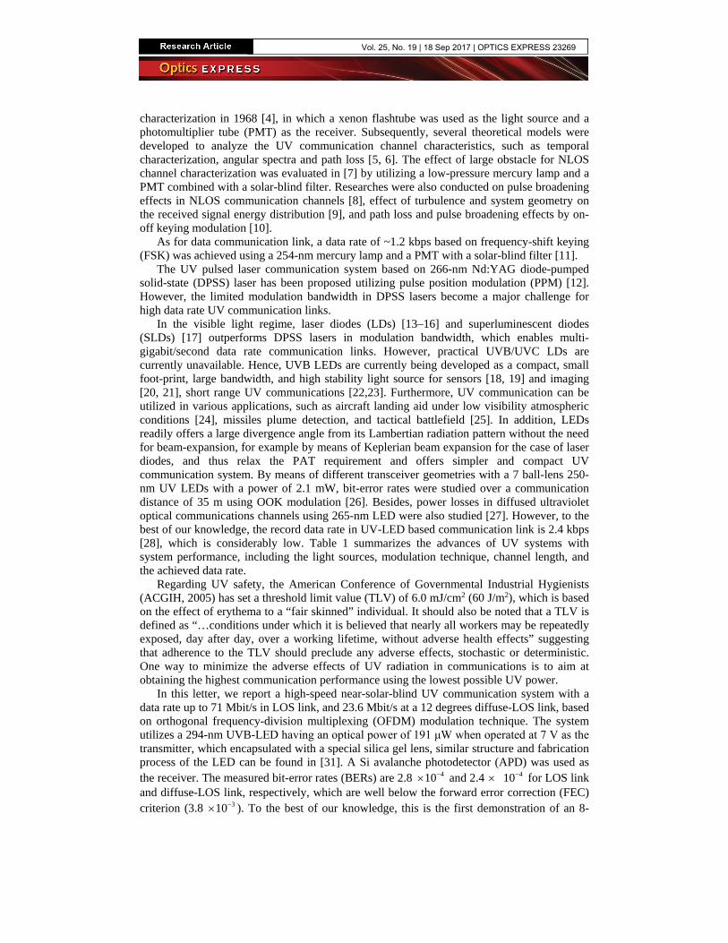
characterization in 1968 [4], in which a xenon flashtube was used as the light source and a photomultiplier tube (PMT) as the receiver. Subsequently, several theoretical models were developed to analyze the UV communication channel characteristics, such as temporal characterization, angular spectra and path loss [5, 6]. The effect of large obstacle for NLOS channel characterization was evaluated in [7] by utilizing a low-pressure mercury lamp and a PMT combined with a solar-blind filter. Researches were also conducted on pulse broadening effects in NLOS communication channels [8], effect of turbulence and system geometry on the received signal energy distribution [9], and path loss and pulse broadening effects by on-off keying modulation [10].
As for data communication link, a data rate of ~1.2 kbps based on frequency-shift keying (FSK) was achieved using a 254-nm mercury lamp and a PMT with a solar-blind filter [11].
The UV pulsed laser communication system based on 266-nm Nd:YAG diode-pumped solid-state (DPSS) laser has been proposed utilizing pulse position modulation (PPM) [12]. However, the limited modulation bandwidth in DPSS lasers become a major challenge for high data rate UV communication links.
In the visible light regime, laser diodes (LDs) [13–16] and superluminescent diodes (SLDs) [17] outperforms DPSS lasers in modulation bandwidth, which enables multi-gigabit/second data rate communication links. However, practical UVB/UVC LDs are currently unavailable. Hence, UVB LEDs are currently being developed as a compact, small foot-print, large bandwidth, and high stability light source for sensors [18, 19] and imaging [20, 21], short range UV communications [22,23]. Furthermore, UV communication can be utilized in various applications, such as aircraft landing aid under low visibility atmospheric conditions [24], missiles plume detection, and tactical battlefield [25]. In addition, LEDs readily offers a large divergence angle from its Lambertian radiation pattern without the need for beam-expansion, for example by means of Keplerian beam expansion for the case of laser diodes, and thus relax the PAT requirement and offers simpler and compact UV communication system. By means of different transceiver geometries with a 7 ball-lens 250-nm UV LEDs with a power of 2.1 mW, bit-error rates were studied over a communication distance of 35 m using OOK modulation [26]. Besides, power losses in diffused ultraviolet optical communications channels using 265-nm LED were also studied [27]. However, to the best of our knowledge, the record data rate in UV-LED based communication link is 2.4 kbps [28], which is considerably low. Table 1 summarizes the advances of UV systems with system performance, including the light sources, modulation technique, channel length, and the achieved data rate.
Regarding UV safety, the American Conference of Governmental Industrial Hygienists (ACGIH, 2005) has set a threshold limit value (TLV) of 6.0 mJ/cm2 (60 J/m2), which is based on the effect of erythema to a “fair skinned” individual. It should also be noted that a TLV is defined as “…conditions under which it is believed that nearly all workers may be repeatedly exposed, day after day, over a working lifetime, without adverse health effects” suggesting that adherence to the TLV should preclude any adverse effects, stochastic or deterministic. One way to minimize the adverse effects of UV radiation in communications is to aim at obtaining the highest communication performance using the lowest possible UV power.
In this letter, we report a high-speed near-solar-blind UV communication system with a data rate up to 71 Mbit/s in LOS link, and 23.6 Mbit/s at a 12 degrees diffuse-LOS link, based on orthogonal frequency-division multiplexing (OFDM) modulation technique. The system utilizes a 294-nm UVB-LED having an optical power of 191 μW when operated at 7 V as the transmitter, which encapsulated with a special silica gel lens, similar structure and fabrication process of the LED can be found in [31]. A Si avalanche photodetector (APD) was used as the receiver. The measured bit-error rates (BERs) are 2.8 4 10−× and 2.4 × 41 0− for LOS link and diffuse-LOS link, respectively, which are well below the forward error correction (FEC) criterion (3.8 3 10−× ). To the best of our knowledge, this is the first demonstration of an 8-
Vol. 25, No. 19 | 18 Sep 2017 | OPTICS EXPRESS 23269
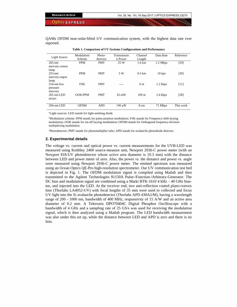
QAMs OFDM near-solar-blind UV communication system, with the highest data rate ever reported.
Table 1. Comparison of UV Systems Configurations and Performance
Light Source Modulation Scheme
Photo-detector
Transmission Power
Channel Length
Data Rate Reference
265-nm mercury-xenon lamp
PPM PMT 25 W 1.6 km 1.2 Mbps [29]
253-nm mercury-argon lamp
PPM PMT 5 W 0.5 km 10 kps [30]
254-nm low pressure mercury
FSK PMT —- 6 m 1.2 kbps [11]
265-nm LED arrays
OOK/PPM PMT 43 mW 100 m 2.4 kbps [28]
294-nm LED OFDM APD 190 μW 8 cm 71 Mbps This work
aLight sources: LED stands for light-emitting diode. bModulation scheme: PPM stands for pulse-position modulation; FSK stands for Frequency-shift keying modulation; OOK stands for on-off keying modulation; OFDM stands for Orthogonal frequency-division multiplexing modulation. cPhotodetector: PMT stands for photomultiplier tube; APD stands for avalanche photodiode detector.
2. Experimental details The voltage vs. current and optical power vs. current measurements for the UVB-LED was measured using Keithley 2400 source-measure unit, Newport 2936-C power meter (with an Newport 818-UV photodetector whose active area diameter is 10.3 mm) with the distance between LED and power meter of zero. Also, the power vs. the distance and power vs. angle were measured using Newport 2936-C power meter. The emitted spectrum was measured using an Ocean Optics QE-Pro high-resolution spectrometer. Our UV communication test bed is depicted in Fig. 1. The OFDM modulation signal is compiled using Matlab and then transmitted to the Agilent Technologies 81150A Pulse-/Function-/Arbitrary-Generator. The DC bias and modulation signal are combined using a Marki BTK-1610 4 kHz – 40 GHz bias-tee, and injected into the LED. At the receiver end, two anti-reflection coated plano-convex lens (Thorlabs LA4052-UV) with focal lengths of 35 mm were used to collected and focus UV light into the Si avalanche photodetector (Thorlabs APD 430A2/M), having a wavelength range of 200 - 1000 nm, bandwidth of 400 MHz, responsivity of 15 A/W and an active area diameter of 0.2 mm. A Tektronix DPO70404C Digital Phosphor Oscilloscope with a bandwidth of 4 GHz and a sampling rate of 25 GS/s was used for receiving the modulation signal, which is then analyzed using a Matlab program. The LED bandwidth measurement was also under this set up, while the distance between LED and APD is zero and there is no lens.
Vol. 25, No. 19 | 18 Sep 2017 | OPTICS EXPRESS 23270
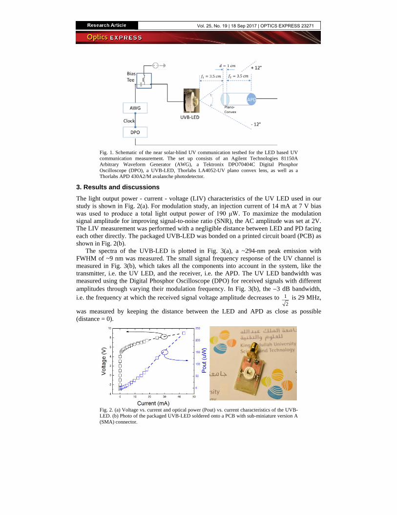
Fig. 1. Schematic of the near solar-blind UV communication testbed for the LED based UV communication measurement. The set up consists of an Agilent Technologies 81150A Arbitrary Waveform Generator (AWG), a Tektronix DPO70404C Digital Phosphor Oscilloscope (DPO), a UVB-LED, Thorlabs LA4052-UV plano convex lens, as well as a Thorlabs APD 430A2/M avalanche photodetector.
3. Results and discussions The light output power - current - voltage (LIV) characteristics of the UV LED used in our study is shown in Fig. 2(a). For modulation study, an injection current of 14 mA at 7 V bias was used to produce a total light output power of 190 μW. To maximize the modulation signal amplitude for improving signal-to-noise ratio (SNR), the AC amplitude was set at 2V. The LIV measurement was performed with a negligible distance between LED and PD facing each other directly. The packaged UVB-LED was bonded on a printed circuit board (PCB) as shown in Fig. 2(b).
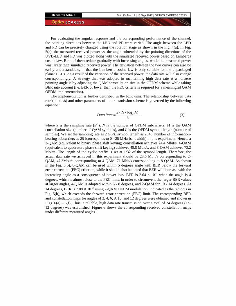
The spectra of the UVB-LED is plotted in Fig. 3(a), a ~294-nm peak emission with FWHM of ~9 nm was measured. The small signal frequency response of the UV channel is measured in Fig. 3(b), which takes all the components into account in the system, like the transmitter, i.e. the UV LED, and the receiver, i.e. the APD. The UV LED bandwidth was measured using the Digital Phosphor Oscilloscope (DPO) for received signals with different amplitudes through varying their modulation frequency. In Fig. 3(b), the −3 dB bandwidth, i.e. the frequency at which the received signal voltage amplitude decreases to 1
2 is 29 MHz,
was measured by keeping the distance between the LED and APD as close as possible (distance = 0).
Fig. 2. (a) Voltage vs. current and optical power (Pout) vs. current characteristics of the UVB-LED. (b) Photo of the packaged UVB-LED soldered onto a PCB with sub-miniature version A (SMA) connector.
Vol. 25, No. 19 | 18 Sep 2017 | OPTICS EXPRESS 23271
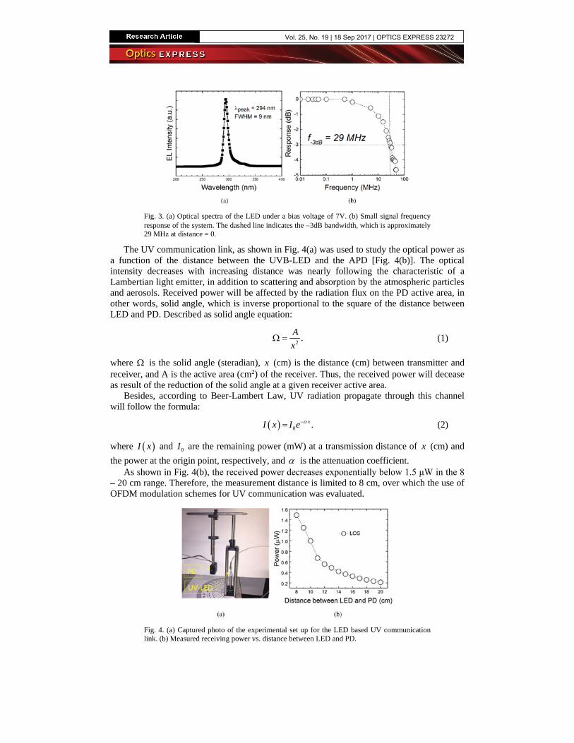
Fig. 3. (a) Optical spectra of the LED under a bias voltage of 7V. (b) Small signal frequency response of the system. The dashed line indicates the −3dB bandwidth, which is approximately 29 MHz at distance = 0.
The UV communication link, as shown in Fig. 4(a) was used to study the optical power as a function of the distance between the UVB-LED and the APD [Fig. 4(b)]. The optical intensity decreases with increasing distance was nearly following the characteristic of a Lambertian light emitter, in addition to scattering and absorption by the atmospheric particles and aerosols. Received power will be affected by the radiation flux on the PD active area, in other words, solid angle, which is inverse proportional to the square of the distance between LED and PD. Described as solid angle equation:
2 .Ax
Ω = (1)
where Ω is the solid angle (steradian), x (cm) is the distance (cm) between transmitter and receiver, and A is the active area (cm2) of the receiver. Thus, the received power will decease as result of the reduction of the solid angle at a given receiver active area.
Besides, according to Beer-Lambert Law, UV radiation propagate through this channel will follow the formula:
( ) 0 .xI x I e α−= (2)
where ( )I x and 0I are the remaining power (mW) at a transmission distance of x (cm) and the power at the origin point, respectively, and α is the attenuation coefficient.
As shown in Fig. 4(b), the received power decreases exponentially below 1.5 μW in the 8 – 20 cm range. Therefore, the measurement distance is limited to 8 cm, over which the use of OFDM modulation schemes for UV communication was evaluated.
Fig. 4. (a) Captured photo of the experimental set up for the LED based UV communication link. (b) Measured receiving power vs. distance between LED and PD.
Vol. 25, No. 19 | 18 Sep 2017 | OPTICS EXPRESS 23272
For evaluating the angular response and the corresponding performance of the channel, the pointing directions between the LED and PD were varied. The angle between the LED and PD can be precisely changed using the rotation stage as shown in the Fig. 4(a). In Fig. 5(a), the measured received power vs. the angle subtended by the pointing directions of the UVB-LED and PD was plotted along with the simulated received power based on Lambert's cosine law. Both of them reduce gradually with increasing angles, while the measured power was larger than simulated received power. The deviation between the two curves can also be easily understandable, in that the Lambert’s cosine law is only suitable for the unpackaged planar LEDs. As a result of the variation of the received power, the data rate will also change correspondingly. A strategy that was adopted in maintaining high data rate at a nonzero pointing angle is by adjusting the QAM constellation size in the OFDM scheme while taking BER into account (i.e. BER of lower than the FEC criteria is required for a meaningful QAM OFDM implementation).
The implementation is further described in the following. The relationship between data rate (in bits/s) and other parameters of the transmission scheme is governed by the following equation:
2 log .
S N MData RateL
× ×= (3)
where S is the sampling rate (s−1), N is the number of OFDM subcarriers, M is the QAM constellation size (number of QAM symbols), and L is the OFDM symbol length (number of samples). We set the sampling rate as 2 GS/s, symbol length as 2048, number of information-bearing subcarriers as 25 (corresponds to 0 - 25 MHz bandwidth) in this experiment. Hence, a 2-QAM (equivalent to binary phase shift keying) constellation achieves 24.4 Mbit/s, 4-QAM (equivalent to quadrature phase shift keying) achieves 48.8 Mbit/s, and 8-QAM achieves 73.2 Mbit/s. The length of the cyclic prefix is set at 1/32 of the symbol length. Therefore, the actual data rate we achieved in this experiment should be 23.6 Mbit/s corresponding to 2-QAM, 47.3Mbit/s corresponding to 4-QAM, 71 Mbit/s corresponding to 8-QAM. As shown in the Fig. 5(b), 8-QAM can be used within 5 degrees angle with BER below the forward error correction (FEC) criterion, while it should also be noted that BER will increase with the increasing angle as a consequence of power loss. BER is 2.64 × 310− when the angle is 4 degrees, which is almost close to the FEC limit. In order to circumvent the larger BER values at larger angles, 4-QAM is adopted within 6 - 8 degrees, and 2-QAM for 10 - 14 degrees. At 14 degrees, BER is 7.08 × 310− using 2-QAM OFDM modulation, indicated as the red dots in Fig. 5(b), which exceeds the forward error correction (FEC) limit. The corresponding BER and constellation maps for angles of 2, 4, 6, 8, 10, and 12 degrees were obtained and shown in Figs. 6(a) – 6(f). Thus, a reliable, high data rate transmission over a total of 24 degrees (+/− 12 degrees) was established. Figure 6 shows the corresponding received constellation maps under different measured angles.
Vol. 25, No. 19 | 18 Sep 2017 | OPTICS EXPRESS 23273
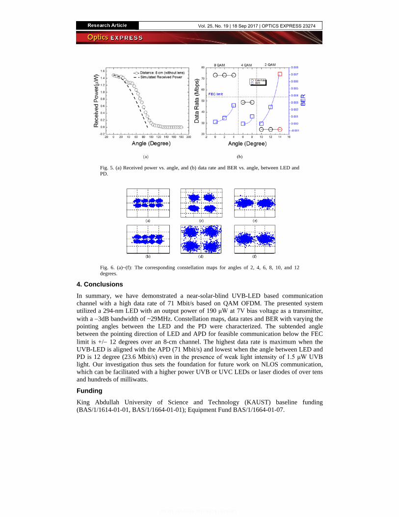
Fig. 5. (a) Received power vs. angle, and (b) data rate and BER vs. angle, between LED and PD.
Fig. 6. (a)~(f): The corresponding constellation maps for angles of 2, 4, 6, 8, 10, and 12 degrees.
4. Conclusions In summary, we have demonstrated a near-solar-blind UVB-LED based communication channel with a high data rate of 71 Mbit/s based on QAM OFDM. The presented system utilized a 294-nm LED with an output power of 190 μW at 7V bias voltage as a transmitter, with a −3dB bandwidth of ~29MHz. Constellation maps, data rates and BER with varying the pointing angles between the LED and the PD were characterized. The subtended angle between the pointing direction of LED and APD for feasible communication below the FEC limit is +/− 12 degrees over an 8-cm channel. The highest data rate is maximum when the UVB-LED is aligned with the APD (71 Mbit/s) and lowest when the angle between LED and PD is 12 degree (23.6 Mbit/s) even in the presence of weak light intensity of 1.5 μW UVB light. Our investigation thus sets the foundation for future work on NLOS communication, which can be facilitated with a higher power UVB or UVC LEDs or laser diodes of over tens and hundreds of milliwatts.
Funding King Abdullah University of Science and Technology (KAUST) baseline funding (BAS/1/1614-01-01, BAS/1/1664-01-01); Equipment Fund BAS/1/1664-01-07.
Vol. 25, No. 19 | 18 Sep 2017 | OPTICS EXPRESS 23274