Embed Size (px)
Citation preview

(7.1)System Architecture
Channels Busses Memory hierarchies Cache design Peripherals Disk structures Displays Parallel machines

(7.2)Channel Architecture (Independent I/O)
In von Neumann machine, all data between memory and I/O must go through ALU–ALU not doing useful computation while this happens»“von Neumann bottleneck”
–add data channels to independently control I/O traffic»channel just simple computer»CPU tells channel operation to perform and
memory address of data•essentially, sends an instruction to the channel
»CPU continues executing while I/O »channel tells CPU when it’s finished
•“interrupt”– same idea on smaller systems
»DMA - direct memory access, controller on each interface card

(7.3)Channel Architecture (continued)

(7.4)Bus Architectures
Channel architecture expensive and relatively inflexible
Smaller, cheaper machines needed more flexibility, leads to bus architecture–easy expansion
(7.5)Bus Architectures (continued)
Bus is simply a set of communication paths– control–data sometimes–address multiplexed
Plug devices (memory, I/O, etc.) into bus

(7.6)Bus Architectures (continued)
Inexpensive versions use CPU to control bus
Expensive (and faster) versions use multiple busses or bus master connections, freeing CPU

(7.7)Bus Architectures (continued)
I/O devices typically look like memory addresses (memory-mapped I/O)
Some bus architectures have separate I/O instructions
Busses can be proprietary (Nubus, Unibus) or standard (VME, PCI)

(7.8)Memory Hierarchies
Match memory speeds to CPU speeds as closely as possible
Problem is memory speed grows more slowly than CPU speed–CPU speed increases 50% per year–memory speed grows at 7% per year–note memory capacity grows at 60% per year»quadruples every 3 years
This means designers want to use more memory to overcome the speed difference

(7.9)Memory Hierarchies (continued)
Use larger main memories and design memory hierarchies
As move lower in pyramid, get slower access and larger capacity
Registers
Memory cacheMain memory
Disk cache
Disk
Tape /optical

(7.10)Memory Hierarchies (continued)
Registers–built into CPU chip–balanced speed with CPU– short distance to access
Cache– smaller, faster memory interposed between CPU and main memory
CPU CacheMain
Memory
word block

(7.11)Cache Design
Idea based on principle of locality of reference– reference one location, high probability that next reference will be close to same address
Caches and main memory use different types of memory–DRAM for main memory–SRAM for cache–DRAM has 4 - 8 times SRAM capacity–SRAM is 8 - 16 times faster and more expensive than DRAM

(7.12)Cache Design (continued)
Issues in cache design–where can a block be placed in the cache?»block placement
–how is a block found if it’s in the cache?»block identification
–which block should be replaced on a miss?»block replacement
–what happens on a write?»write strategy

(7.13)Cache Design(continued)
Block placement policies–all policies involve conflict–direct mapped
»each main memory block can only appear in one possible place in the cache
– full associative mapping»any block can appear in any place in the
cache
– set associative mapping»each block can appear in only a small
set of locations in the cache

(7.14)Direct Mapped Cache
Cache
Main memory
OffsetBlock #Tag

(7.15)Full Associative Cache
Cache
Main memory
Tag Offset

(7.16)Set Associative Cache
Cache
Main memory
OffsetBlock #Tag

(7.17)Cache Design (continued)
Block identification uses the tag field in all cases Block replacement
– least recently used– first in, first out
» replace oldest block in cache– random– data from actual traces show little difference
between LRU and random» both better than FIFO
– miss rate data
Associativity 2-way 4-way 8-way
Size LRU Rand LRU Rand LRU Rand
16 KB 5.18% 5.69% 4.67% 5.29% 4.39% 4.96%
64 KB 1.88% 2.01% 1.54% 1.66% 1.39% 1.53%
128 KB 1.15% 1.17% 1.13% 1.13% 1.12% 1.12%

(7.18)Cache Design (continued)
Write strategy–writes constitute about 15% of cache accesses–write through
»write to cache and corresponding main memory block
»easier to implement»main memory always has the correct value
–write back»write to cache only; copy any cache blocks
written to when they are replaced» faster; multiple writes to same block only cause
one write to main memory Block size typically 16 bytes or 32 bytes Another technique is to use separate
instruction and data caches Or use two caches
–eg, I 486 has 8KB first level cache on CPU chip, add second level on computer board

(7.19)Peripherals
Peripherals are anything added to the system beyond the CPU and the main memory hierarchy
Pointing devices–mouse, trackball, tablet, touch screen, joystick
Printers Communication devices
– local area networks Displays Long term storage devices
–magnetic disks–optical disks–magnetic tape
(7.20)Magnetic Disk Structures
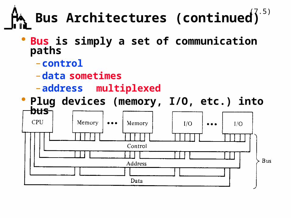
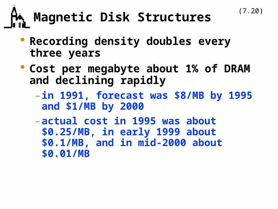
Recording density doubles every three years
Cost per megabyte about 1% of DRAM and declining rapidly– in 1991, forecast was $8/MB by 1995 and $1/MB by 2000
–actual cost in 1995 was about $0.25/MB, in early 1999 about $0.1/MB, and in mid-2000 about $0.01/MB

(7.21)Magnetic Disk Structures (continued)
Disks are organized into– surfaces and platters
»1 - 10 platters»2” - 14” in diameter
– tracks»500 - 2000 per surface
– sectors»32 - 64 per track» typically 512 bytes for small systems,
larger (4096) for big systems»smallest portion that can be read or
written– cylinders
Heads fly over surface of disk

(7.22)Magnetic Disk Structures (continued)
Accessing data depends on total of– seek time (about 10 ms for fast disk)– latency
»8 ms at 3600 rpm»6 ms at 5400 rpm»4 ms at 7200 rpm
–data layout on disk can significantly affect performance»consecutive sectors, down cylinders
Disk caching now common–hardware caches on drives to speed controller/memory transfers
– software caches in memory»read several sectors in a row

(7.23)Computer Display Devices
All modern computer displays are raster scan devices– individual dots (pixels) are on or off– color displays use three pixels (RGB) to produce color
Parameters are– resolution
»640 H x 480 V up to 1600 H x 1200 V»note 4 to 3 aspect ratio
–number of colors or gray levels»2 = monochrome, up to 16 million»greater number requires more memory for
each pixel»eg, 8 bits of memory for each of RGB gives
256x256x256 colors– scan rate
»how often screen is painted (60 Hz - 72 Hz)» interlaced or non-interlaced

(7.24)Computer Display Devices (continued)
Image to be displayed is transferred to frame buffer, which paints it repetitively on the screen–use of color map, or color lookup table, reduces amount of memory required in the frame buffer
– to avoid being seen by user, changes to frame buffer »take place during vertical retrace of beam» involve two frame buffers; display from one while
change second, then switch buffers Graphics accelerators are special chips that
perform common graphics operations in hardware–window creation, block moves– scrolling–graphics primitives
Flat panel displays (LCD displays) are a future hot item

(7.25)Parallel Machines
If speed improvements to a single processor aren’t good enough, use several processors–major questions are
»organization»scalability
Four major categories of computer–SISD = single instruction, single data–SIMD = single instruction, multiple data–MISD = multiple instruction, single data–MIMD = multiple instruction, multiple data

(7.26)Parallel Machines (continued)
Early parallel computers were SIMD, current ones are mostly MIMD–SIMD good for massively parallel data sets, probably used for special purpose computers (array processors)»64K 1-bit processors
–MIMD applicable to wider range of problems, can be partitioned

(7.27)Parallel Machines (continued)
One approach to a parallel computer is a single shared memory architecture– independent processors can access single central memory
– called multiprocessors or symmetric multiprocessors
– typically for small number of processors (32)»because faster processors need greater
memory bandwidth– connection by bus, ring, or crossbar switch–advantages are
»similar to uniprocessor model of computation»easier to program» lower latency for communication
–disadvantages»adequate performance requires hardware
support for memory sharing

(7.28)Parallel Machines (continued)
Another approach is a distributed shared memory architecture–each machine has local memory, but organized as a single address space
– communication simple (memory loads/stores)»but possibly longer latency
– typically for 64 - 1K processors

(7.29)Parallel Machines (continued)
Final approach is multicomputers–each machine has local memory, but address space is private
–use message passing to communicate, request memory from another processor»communication made explicit
– typical interconnection pattern»hypercube = 2N nodes, each connects to N
neighbors»note hypercube can operate as SIMD or
MIMD»multistage switch
– slower memory access than shared memory (factor of 10)
– typically for 256 - 4K processors