Embed Size (px)
Citation preview

4/14/2009 7_2 The T Junction power Divider.doc 1/1
Jim Stiles The Univ. of Kansas Dept. of EECS
7.2 – The T-Junction Power Divider
Reading Assignment: pp. 315-318 Three-port couplers are also known as T-Junction Couplers, or T-Junction Dividers. HO: THE T-JUNCTION COUPLER We will study three standard T-Junction couplers: HO: THE RESISTIVE DIVIDER HO: THE LOSSLESS DIVIDER HO: CIRCULATORS Now let’s consider a 3dB power divider from another viewpoint; let’s consider the scattering matrix of a (nearly) ideal 3dB power divider. HO: THE (NEARLY) IDEAL POWER DIVIDER This ideal 3dB power divider can be constructed! It is the Wilkinson Power Divider—the subject of the next section.

4/14/2009 The 3 port Coupler.doc 1/1
Jim Stiles The Univ. of Kansas Dept. of EECS
The T-Junction Coupler Say we desire a matched and lossless 3-port coupler.
Absolutely true! Our desire in this case will be unfulfilled. There are, however, a few designs that come close. 1. The Lossless Divider – As the name states, this coupler is lossless. It is likewise reciprocal, and thus is not matched. 2. The Resistive Divider – As the name implies, this coupler is lossy. However, it is both matched and reciprocal. 3. The Circulator – This three-port coupler is both matched and (ideally) lossy. This of course means that it is not reciprocal! 4. The Wilkinson Divider - Like the resistive divider, it is matched and reciprocal, and thus is lossy. However, it is lossy in a way that is not apparent when power is divided (i.e., power can be divided without loss). As a result, the Wilkinson Power Divider is in most ways as ideal a T-junction as there is. Accordingly, it has its very own section in your textbook!
Wait a minute! I already told you that a matched, lossless, reciprocal 3-port device of any kind is a physical impossibility!

4/14/2009 The Resistive Divider.doc 1/2
Jim Stiles The Univ. of Kansas Dept. of EECS
The Resistive Divider Consider the resistive power divider: This symmetric power divider will be matched at port 1 if R is selected as:
( ) ( )0 0 0
0
0
2
1 52
Z R R Z R ZR ZR
Z. R
= + + +
+= +
= +
Solving this equation, we find that port 1 is matched if:
0
3ZR =
Z0
Z0
Z0
Port 1
Port 2
Port 3
R R
R
Z0
Z0
Z0 R R
R
4/14/2009 The Resistive Divider.doc 2/2
Jim Stiles The Univ. of Kansas Dept. of EECS
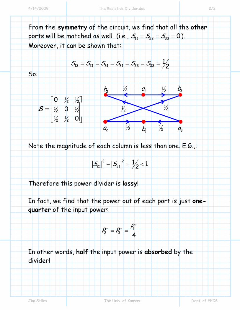
From the symmetry of the circuit, we find that all the other ports will be matched as well (i.e., 11 22 33 0S S S= = = ). Moreover, it can be shown that:
12 21 31 31 23 3212S S S S S S= = = = = =
So:
1 12 2
1 12 2
1 12 2
00
0
⎡ ⎤⎢ ⎥⎢ ⎥⎢ ⎥⎣ ⎦
=S
Note the magnitude of each column is less than one. E.G.,:
2221 31
1 12S S+ = < Therefore this power divider is lossy! In fact, we find that the power out of each port is just one-quarter of the input power:
12 3 4
PP P+
− += =
In other words, half the input power is absorbed by the divider!
1a
2a 1b
2b 3b
3a
12 1
2
12 1
2
12 1
2

4/14/2009 The Lossless Divider.doc 1/4
Jim Stiles The Univ. of Kansas Dept. of EECS
The Lossless Divider Consider the lossless power divider: To be ideal, we want 11 0S = . Thus, when ports 2 and port 3 are terminated in matched loads, the input impedance at port 1 must be equal to Z01. This will only be true if the values Z02 and Z03 are selected such that:
102 03
0102 03 02 03
1 1 Z ZZZ Z Z Z
−⎛ ⎞
= + =⎜ ⎟ +⎝ ⎠
Note however that this circuit is not symmetric, thus we find that 22 0S ≠ and 33 0S ≠ !
Z01
Z03
Z02
Port 1
1P +
Z01
Z03
Z02
Port 1
Port 2
Port 3
1P +
2P −
3P −

4/14/2009 The Lossless Divider.doc 2/4
Jim Stiles The Univ. of Kansas Dept. of EECS
It is evident that this divider is lossless (no resistive components), so that:
1 2 3P P P+ − −= +
where 1P + is the power incident (and absorbed if 11 0S = ) on port 1, and 2P − and 3P − is the power absorbed by the matched loads of ports 2 and 3. Unless 02 03Z Z= , the power will not be divide equally between
2P − and 3P − . With a little microwave circuit analysis, it can be shown that the division ratio α is :
032
3 02
ZPP Z
α−
−= =
Thus, if we desire an ideal ( 11 0S = ) divider with a specific division ratio α , we will find that:
( )02 0111Z Z α= +
and: ( )03 01 1Z Z α= +
Q: I don’t understand how this is helpful. Don’t we typically want the characteristic impedance of all three ports to be equal to the same value (e.g., 01 02 03 0Z Z Z Z= = = )?

4/14/2009 The Lossless Divider.doc 3/4
Jim Stiles The Univ. of Kansas Dept. of EECS
A: True ! A more practical way to implement this divider is to use a matching network, such as a quarter wave transformer, on ports 2 and 3:
But beware! Recall that this matching network will work perfectly at only one frequency. This lossless divider has a scattering matrix (at the design frequency) of this form:
2 2
22 232
32 332
0 j j
j
j
S SS S
− −
−
−
⎡ ⎤⎢ ⎥= ⎢ ⎥⎢ ⎥⎣ ⎦
S
where the (non-zero!) values of 22S , 23S , 32S , and 33S depend on the division ratio α. Note that if we desire a 3 dB divider (i.e., 1α = ), then:
02 03 012Z Z Z= =
Z0 0 02Z Z
Port 1
Port 2
Port 3
1P +
2P −
3P −
Z0
Z0 4λ
4λ
0 03Z Z

4/14/2009 The Lossless Divider.doc 4/4
Jim Stiles The Univ. of Kansas Dept. of EECS
This 3dB lossless divider (where 02 03 012Z Z Z= = ), would have this design:
Along with this scattering matrix:
2 2
1 12 22
1 12 22
0 j j
j
j
− −
− −
− −
⎡ ⎤⎢ ⎥= ⎢ ⎥⎢ ⎥⎣ ⎦
S
Z0 0 2Z
Port 1
Port 2
Port 3
1P +
2P −
3P −
Z0
Z0 4λ
4λ
0 2Z
1a
2a 1b
2b 3b
2j− 3a
2j− 2
j−
2j−
12 1
2 12
− 12
−

4/14/2009 Circulators.doc 1/4
Jim Stiles The Univ. of Kansas Dept. of EECS
Circulators A circulator is a matched, lossless but non-reciprocal 3-port device, whose scattering matrix is ideally:
0 0 11 0 00 1 0
⎡ ⎤⎢ ⎥= ⎢ ⎥⎢ ⎥⎣ ⎦
S
Circulators use anisotropic ferrite materials, which are often “biased” by a permanent magnet! The result is a non-reciprocal device! First, we note that for a circulator, the power incident on port 1 will exit completely from port 2:
2 1P P− +=
Pardon me while I sarcastically yawn. This unremarkable behavior is likewise true for the simple circuit below, which requires just a length of transmission line. Oh please, continue to waste our valuable time.
Z0 port 1
port 2 1P +
2 1P P− +=
port 3 (useless)
ΓL=0 This is not a circulator!
1a
2a 1b
2b 3b
3a
1 1
1

4/14/2009 Circulators.doc 2/4
Jim Stiles The Univ. of Kansas Dept. of EECS
True! But a transmission line, being a reciprocal device, will likewise result in the power incident on port 2 of your simple circuit to exit completely from port 1 ( 1 2P P− += ):
But, this is not true for a circulator! If power is incident on port 2, then no power will exit port 1 ! Likewise, power flowing into port 3 will exit—port 1! It is evident, then how the circulator gets its name: power appears to circulate around the device, a behavior that is emphasized by its device symbol:
Z0 port 1
port 2
2P +
1 2P P− +=
port 3 (useless)
ΓL=0
Q: You have been surprisingly successful in regaining my interest. Please tell us then, just where does the power incident on port 2 go?
A: It will exit from port 3 !
0 1 01 0 00 0 0
je β−
⎡ ⎤⎢ ⎥= ⎢ ⎥⎢ ⎥⎣ ⎦
S

4/14/2009 Circulators.doc 3/4
Jim Stiles The Univ. of Kansas Dept. of EECS
We can see that, for example, a source at port 2 “thinks” it is attached to a load at port 3, while a load at port 2 “thinks” it is attached to a source at port 1! This behavior is useful when we want to use one antenna as both the transmitter and receiver antenna. The transmit antenna (i.e., the load) at port 2 gets its power from the transmitter at port 1. However, the receive antenna (i.e., the source) at port 2 delivers its power to the receiver at port 3!
1 2
3
1P +
3P −
3P +
2P −
2P + 1P −

4/14/2009 Circulators.doc 4/4
Jim Stiles The Univ. of Kansas Dept. of EECS
It is particularly important to keep the transmitter power from getting to the receiver. To accomplish this, the antenna must be matched to the transmission line. Do you see why? Finally, we should note some major drawbacks with a circulator: 1. They’re expensive. 2. They’re heavy. 3. The generally produce a large, static magnetic field.
4. They typically exhibit a large insertion loss (e.g., 2 22
21 32 13 0.75S S S= = ≈ ).
Tx
Rx

4/14/2009 The T Junction Power Divider.doc 1/4
Jim Stiles The Univ. of Kansas Dept. of EECS
The (nearly) Ideal T-Junction
Power Divider
Recall that we cannot build a matched, lossless reciprocal three-port device.
So, let’s mathematically try and determine the scattering matrix of the best possible T-junction 3 dB power divider. To efficiently divide the power incident on the input port, the port (port 1) must first be matched (i.e., all incident power should be delivered to port 1):
11 0S = Likewise, this delivered power to port 1 must be divided efficiently (i.e., without loss) between ports 2 and 3. Mathematically, this means that the first column of the scattering matrix must have magnitude of 1.0:
1P + 10.5P +
10.5P + Power Divider 1
2
3

4/14/2009 The T Junction Power Divider.doc 2/4
Jim Stiles The Univ. of Kansas Dept. of EECS
22 2
11 21 31 1S S S+ + = Since we have already determined that 11 0S = , this simply means :
2221 31 1S S+ =
Provided that we wish to evenly divide the input power, we can conclude from the expression above that:
2221 31 21 31
1 12 2
S S S S= = ∴ = =
Note that this device would take the power into port 1 and divide into two equal parts—half exiting port 2, and half exiting port3 (provided ports 2 and 3 are terminated in matched loads!).
222 21 1 1 3 31 1 10 5 0 5P S P . P P S P . P− + + − + += = = =
In addition, it is desirable that ports 2 and 3 be matched ( the whole device is thus matched):
22 33 0S S= = And also desirable that ports 2 and 3 be isolated:
23 32 0S S= =

4/14/2009 The T Junction Power Divider.doc 3/4
Jim Stiles The Univ. of Kansas Dept. of EECS
This last requirement ensures that no signal incident on port 2 (e.g., reflected from a load) will “leak” into port 3—and vice versa. This ideal 3 dB power divider could therefore have the form:
2 2
2
2
00 00 0
j j
j
j
− −
−
−
⎡ ⎤⎢ ⎥= ⎢ ⎥⎢ ⎥⎣ ⎦
S
Since we can describe this ideal power divider mathematically, we can potentially build it physically! Q: Huh!? I thought you said that a matched, lossless, reciprocal three-port device is impossible? A: It is! This divider is clearly a lossy device. The magnitudes of both column 2 and 3 are less than one:
222 212 22 32 2 0 0 0 5 1 0jS S S . .−+ + = + + = <
22 2 2
13 23 33 2 0 0 0 5 1 0jS S S . .−+ + = + + = < Note then that half the power incident on port 2 (or port 3) of this device would exit port 1 (i.e., reciprocity), but no power would exit port 3 (port2), since ports 2 and 3 are isolated. I.E.,:
1a
2a 3a 1b
2b 3b
2j−
3a
2j− 2
j−
2j−

4/14/2009 The T Junction Power Divider.doc 4/4
Jim Stiles The Univ. of Kansas Dept. of EECS
221 12 2 2 3 32 20 5 0P S P . P P S P− + + − += = = =
2 2
1 13 3 3 2 23 30 5 0P S P . P P S P− + + − += = = = Q: Any ideas on how to build this thing? A: Note that the first column of the scattering matrix is precisely the same as that of the lossless 3 dB divider. Also note that since the device is lossy, the design must include some resistors. Lossless Divider + resistors = The Wilkinson Power Divider Q: What is the Wilkinson Power Divider? A: It’s the subject of our next section!