Embed Size (px)
Citation preview
73.09.02.010_FR_EPC – EPC FINAL PERFORMANCE TEST REPORT
Grand River Energy Center Unit 3
KED PROJECT NO. 2014-071
ISSUED: 10/25/2017
REVISION 0 – Initial Issue
Rev. Prepared by Checked by Comments
0 Adam Decker Parag Pathak Initial Issue
KIEWIT ENGINEERING & DESIGN CO.
Engineers • Consultants
Corporate Office: 9401 Renner Boulevard
Lenexa • Kansas 66219 • USA
PHN 913-928-7000 • FAX 913-689-4500
Grand River Energy Center Unit 3 KED Project No. 2014-071 TOC 73.09.02.010_FR_EPC /0/Initial Issue
EPC – FINAL PERFORMANCE TEST REPORT
TABLE OF CONTENTS
SECTION 1: EXECUTIVE SUMMARY
1.1 Overview .................................................................................................... 1
SECTION 2: TEST DESCRIPTION
2.1 Test Overview ............................................................................................ 3
2.2 Test Facility Information ............................................................................. 3
2.3 Test Boundary ............................................................................................ 3
2.4 Key Party Representatives ......................................................................... 3
SECTION 3: TEST EQUIPMENT
3.1 Equipment Overview .................................................................................. 5
3.2 Equipment Information ............................................................................... 5
3.3 DAS Description ......................................................................................... 5
3.4 Calibration Summary .................................................................................. 5
SECTION 4: TEST DEVIATIONS AND DISCUSSION
4.1 Major Test Deviations ................................................................................. 6
4.2 Test Discussion .......................................................................................... 7
SECTION 5: DATA COLLECTION AND CALCULATIONS
5.1 Data Collection ......................................................................................... 10
5.2 Data Reduction ......................................................................................... 10
5.3 Definition of Terms ................................................................................... 10
5.4 Correction Factors .................................................................................... 12
5.5 Test Calculations ...................................................................................... 14
SECTION 6: TEST RESULTS AND CONCLUSIONS
6.1 Test Results ............................................................................................. 15
6.2 Test Conclusions ...................................................................................... 15
Grand River Energy Center Unit 3 KED Project No. 2014-071 TOC 73.09.02.010_FR_EPC /0/Initial Issue
APPENDICES
Appendix A Test Calculations
Appendix B Unit Stability Analysis
Appendix C Test Uncertainty Analysis
Appendix D Test Equipment Information
Appendix E Equipment Calibrations
Appendix F Correction Curves
Appendix G Performance Test Data
Appendix H Fuel Analysis
Appendix I Signed Deviation Letter
Grand River Energy Center Unit 3 KED Project No. 2014-071 TOC 73.09.02.010_FR_EPC /0/Initial Issue
REFERENCES
Engineer, Procure and Construct Contract (EPC Contract)
ASME PTC Test Codes: 1-2011, 4.4-2008, 6.2-2011,19.1-2005, 19.2-2010, 19.3-2004, 19.5-2004, 22-2005, 46-1996
ASTM Standards: D1945-1996, D3588-1998
AGA Report 8
ASME Steam Tables – 1997
ASHRAE Psychrometric Properties – 2009
GPA 2145-2009
Grand River Energy Center Unit 3 KED Project No. 2014-071 094-1 73.09.02.010_FR_EPC /0/Initial Issue
SECTION 1
EXECUTIVE SUMMARY
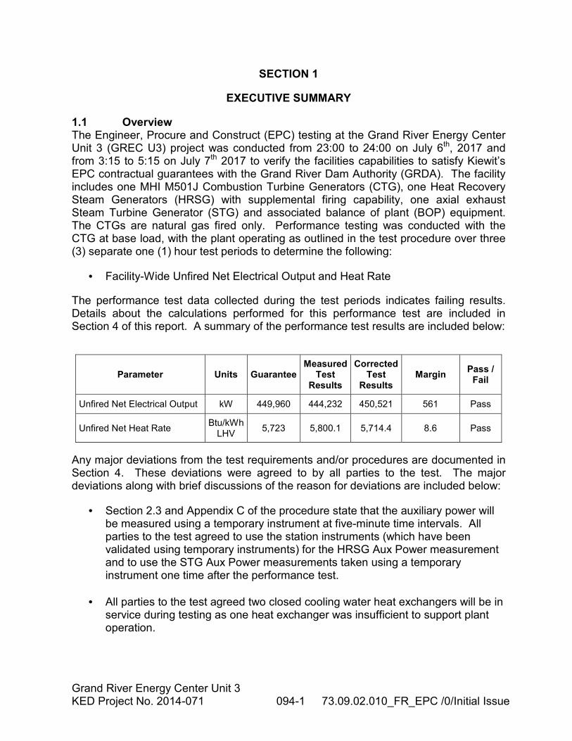
1.1 Overview The Engineer, Procure and Construct (EPC) testing at the Grand River Energy Center Unit 3 (GREC U3) project was conducted from 23:00 to 24:00 on July 6th, 2017 and from 3:15 to 5:15 on July 7th 2017 to verify the facilities capabilities to satisfy Kiewit’s EPC contractual guarantees with the Grand River Dam Authority (GRDA). The facility includes one MHI M501J Combustion Turbine Generators (CTG), one Heat Recovery Steam Generators (HRSG) with supplemental firing capability, one axial exhaust Steam Turbine Generator (STG) and associated balance of plant (BOP) equipment. The CTGs are natural gas fired only. Performance testing was conducted with the CTG at base load, with the plant operating as outlined in the test procedure over three (3) separate one (1) hour test periods to determine the following:
• Facility-Wide Unfired Net Electrical Output and Heat Rate
The performance test data collected during the test periods indicates failing results. Details about the calculations performed for this performance test are included in Section 4 of this report. A summary of the performance test results are included below:
Parameter Units Guarantee Measured
Test Results
Corrected Test
Results Margin
Pass / Fail
Unfired Net Electrical Output kW 449,960 444,232 450,521 561 Pass
Unfired Net Heat Rate Btu/kWh
LHV 5,723 5,800.1 5,714.4 8.6 Pass
Any major deviations from the test requirements and/or procedures are documented in Section 4. These deviations were agreed to by all parties to the test. The major deviations along with brief discussions of the reason for deviations are included below:
• Section 2.3 and Appendix C of the procedure state that the auxiliary power will be measured using a temporary instrument at five-minute time intervals. All parties to the test agreed to use the station instruments (which have been validated using temporary instruments) for the HRSG Aux Power measurement and to use the STG Aux Power measurements taken using a temporary instrument one time after the performance test.
• All parties to the test agreed two closed cooling water heat exchangers will be in service during testing as one heat exchanger was insufficient to support plant operation.
Grand River Energy Center Unit 3 KED Project No. 2014-071 094-2 73.09.02.010_FR_EPC /0/Initial Issue
• All parties to the test agreed the fuel gas heater 3 way gas bypass valve will not be closed during the testing. This is inconsistent with the thermal design of the plant, but required by MHPSA to support CTG operation.
• All parties to the test agreed that an IGV inspection shall not be performed within 24 fired hours of the start of testing.
• All parties to the test agreed that a separate pretest need not be performed.
• All parties to the test agreed that in order to accurately measure the cooling steam going to the gas turbine, the HP backup steam warming line and the associated DSH (03-V035635 and 03-TV-035636) were to be closed for the duration of the testing.
• All parties to the test agreed that there shall be no load change between test runs 2 and 3 due to the length of time required to get the CTG back in “high power” mode after a load change.
The following deviations from the test requirements and/or procedures occurred during the performance test. The deviations along with brief discussions of the reason for deviation are included below:
• None
END OF SECTION
Grand River Energy Center Unit 3 KED Project No. 2014-071 094-3 73.09.02.010_FR_EPC /0/Initial Issue
SECTION 2
TEST DESCRIPTION
2.1 Test Overview The objective of the EPC Performance Test was to determine the capability of the facility to satisfy the guarantees set forth in the contractual agreement to GRDA. All performance testing was conducted with the CTGs at base load with the chiller off and the HRSG unfired.
The Performance Test for the GREC U3 EPC was conducted from 23:00 to 24:00 on July 6th, 2017 and from 3:15 to 5:15 on July 7th 2017. The performance test was conducted over three (3) one (1) hour test periods to determine the following:
• Facility-Wide Unfired Net Electrical Output and Heat Rate
2.2 Test Facility Information The Grand River Energy Center Unit 3 is a new power production facility located on the property of the existing Grand River Energy Center near Chouteau, Oklahoma. The facility consists of one MHI M501J Combustion Turbine Generator (CTG), one three-pressure Heat Recovery Steam Generator (HRSG) with supplemental firing capability, one axial exhaust Steam Turbine Generator (STG) and associated Balance of Plant (BOP) equipment.
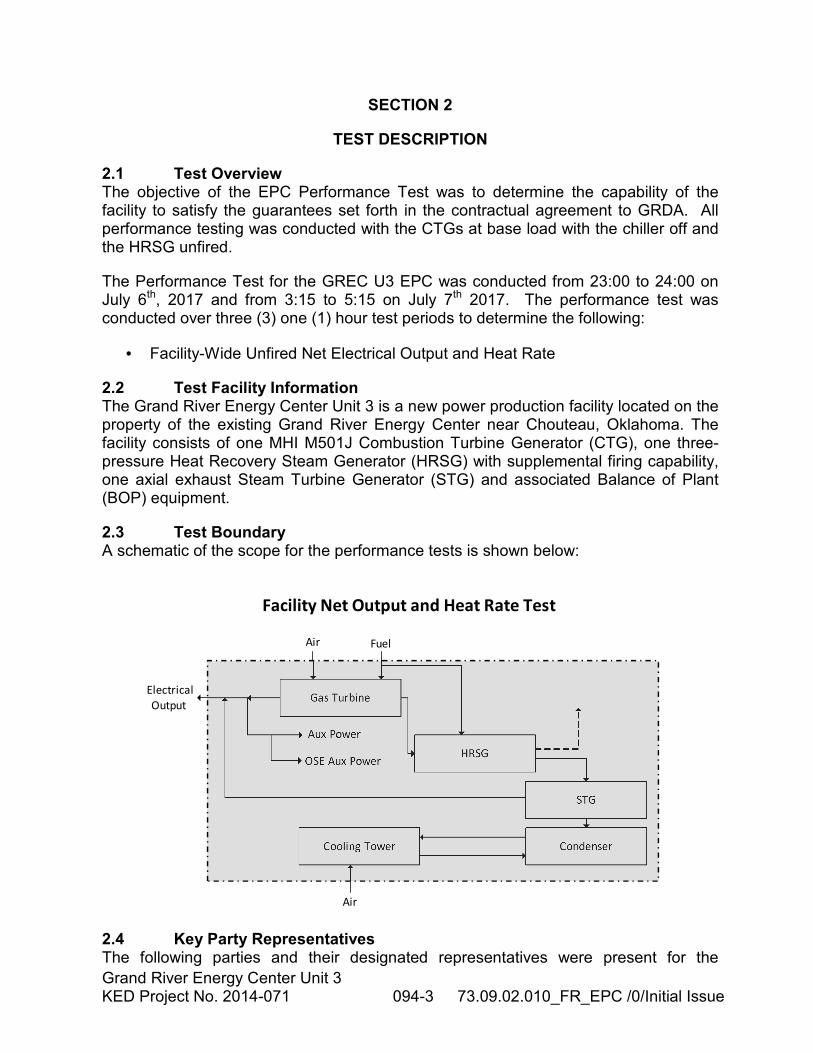
2.3 Test Boundary A schematic of the scope for the performance tests is shown below:
Facility Net Output and Heat Rate Test
Gas Turbine
HRSG
STG
CondenserCooling Tower
OSE Aux Power
Aux Power
FuelAir
Electrical
Output
Air
2.4 Key Party Representatives The following parties and their designated representatives were present for the
Grand River Energy Center Unit 3 KED Project No. 2014-071 094-4 73.09.02.010_FR_EPC /0/Initial Issue
Performance Tests.
Kiewit: Adam Decker, Parag Pathak, Chris Stelzer, Russ McLandsborough
GRDA: Jammie Burrow
B&V: Travis Brockmeyer, Erik Keltner
END OF SECTION
Grand River Energy Center Unit 3 KED Project No. 2014-071 094-5 73.09.02.010_FR_EPC /0/Initial Issue
SECTION 3
TEST EQUIPMENT
3.1 Equipment Overview To the greatest extent possible the test data was monitored and recorded by the permanent plant instrumentation using the Facility’s Distributed Control System (DCS). Temporary test instrumentation and metering equipment was used where there was not permanent plant instrumentation and/or where performance test instrument accuracy was required. Data from the DCS was recorded electronically at 10-second time intervals and temporary test instruments was recorded electronically at 30-second time intervals.
3.2 Equipment Information The general information for the temporary and permanent plant instrumentation used during the performance test is included in Appendix D and includes the following:
• Measured Parameter
• Instrument Location
• Instrument Tag Number
3.3 DAS Description Performance test data were recorded from permanent plant instruments via the DCS, temporary test instrumentation, and manual data taken by personnel. Temporary instrument measurements were compiled to centralized computers provided by McHale Performance. Following the completion of the performance test, this data was distributed to all key witnessing parties. Data was gathered every 10 or 30 seconds.
3.4 Calibration Summary Instruments used for data collection were classified as Primary or Secondary before commencement of the performance test. A Primary instrument is any instrument used in the performance test calculations. All other instruments recording data during testing are considered secondary instruments.
All Primary instruments were calibrated by a third party within 6 months prior to the start of testing with the exception of flow meters. Primary instruments were calibrated to a NIST traceable standard. Secondary instruments having factory calibrations were acceptable. Secondary instruments were required for loop calibration before commencement of testing.
Copies of the calibration certificates were provided to interested parties upon request. The calibration certificates are included in Appendix E.
END OF SECTION
Grand River Energy Center Unit 3 KED Project No. 2014-071 094-6 73.09.02.010_FR_EPC /0/Initial Issue
SECTION 4
TEST DEVIATIONS AND DISCUSSION
4.1 Major Test Deviations The following deviations from the test requirements and/or procedures are documented along with brief discussions of the reason for deviation below: 4.1.1 Test Deviations Discussed Prior to Testing The following major deviations from the test requirements and/or procedures were discussed and agreed to by all parties to the test prior to testing. The major deviations along with brief discussions of the reason for deviation are included below:
• Section 2.3 and Appendix C of the procedure state that the auxiliary power will be measured using a temporary instrument at five-minute time intervals. All parties to the test agreed to use the station instruments (which have been validated using temporary instruments) for the HRSG Aux Power measurement and to use the STG Aux Power measurements taken using a temporary instrument one time after the performance test.
• All parties to the test agreed two closed cooling water heat exchangers will be in service during testing as one heat exchanger was insufficient to support plant operation.
• All parties to the test agreed the fuel gas heater 3 way gas bypass valve will not be closed during the testing. This is inconsistent with the thermal design of the plant, but required by MHPSA to support CTG operation.
• All parties to the test agreed that an IGV inspection shall not be performed within 24 fired hours of the start of testing.
• All parties to the test agreed that a separate pretest need not be performed.
• All parties to the test agreed that in order to accurately measure the cooling steam going to the gas turbine, the HP backup steam warming line and the associated DSH (03-V035635 and 03-TV-035636) were to be closed for the duration of the testing.
• All parties to the test agreed that there shall be no load change between test runs 2 and 3 due to the length of time required to get the CTG back in “high power” mode after a load change.
4.1.2 Test Deviations Found During Testing The following major deviations from the test requirements and/or procedures occurred during the performance test. The major deviations along with brief discussions of the reason for deviation are included below:
Grand River Energy Center Unit 3 KED Project No. 2014-071 094-7 73.09.02.010_FR_EPC /0/Initial Issue
• None
4.2 Test Discussion The following are not test deviations, but are items of note:
• At this time, testing was only conducted for the unfired conditions.
• The vacuum pump heat exchangers were be run on service water in between test runs, and switched to circulating water for the test runs to minimize fouling of the strainers and heat exchangers.
4.2.1 Other Test Deviations The following are not deviations to the CTG test, but are deviations to the other tests performed simultaneously. They are included to give a more complete picture of the testing.
STG Test
• Section 3.5.2.7 of the procedure states the unfired fDesign is 0.0693. All parties to the test agreed the correct value is 0.0369.
• Section 2.3 and Appendix C of the procedure state that the auxiliary power will be measured using a temporary instrument at five-minute time intervals. All parties to the test agreed to use the STG Aux Power measurements taken using a temporary instrument one time after the performance test.
• One of the steam turbine LP balance pipe sensing lines on DP2 was plugged and could not be cleared. All parties to the test agreed to use the design value for the flows through the LP balance piping.
• All parties to the test agreed that there shall be no load change between test runs 2 and 3 due to the length of time required to get the CTG back in “high power” mode after a load change.
• The data collected during the N2 packing test did not evaluate into a result that made sense. The data predicts approximately 36% N2 packing leakage. MHPS believes the location of the HP to LP balance piping is influencing the measurements taken during the N2 packing test. For results purposes, the N2 packing leakage was calculated as follows:
��� = ���_� + ���_�� + ���_��� − ���_��� − ���_�� − ���_����� − ���_��_��− ���� − ���
Where UN2 is the uncertainty of the calculated N2 flow and QCRH_Measured is the CRH flow measured using the CRH flow element.
Grand River Energy Center Unit 3 KED Project No. 2014-071 094-8 73.09.02.010_FR_EPC /0/Initial Issue
• The stability of the LP steam flow was outside the procedure limits during test run 2. In order to meet the procedure stability criteria, the analysis period for test run 2 was changed from 3:15-4:15 to 3:45-4:15.
• The leakage out of the cycle was greater than the test code requirement of 0.25% of the condensate flow. This leakage has been subtracted from calculated flows on a flow weighted basis.
HRSG Test
• Appendix C of the procedure states the auxiliary power will be measured using a temporary instrument. All parties to the test agreed to use the station instruments (which have been validated using temporary instruments) for this measurement.
• All parties to the test agreed that there shall be no load change between test runs 2 and 3 due to the length of time required to get the CTG back in “high power” mode after a load change.
• The HP feedwater flow did not meet the stability criteria for variation during a test run listed in the test procedure for any of the test runs.
• The TCA flow did not meet the stability criteria for variation from the reference conditions listed in the test procedure for any of the test runs.
• The TCA duty did not meet the stability criteria for variation from the reference conditions listed in the test procedure for any of the test runs
• The measured HRH temperature at the STG was used to calculate the HRSG performance as the HRH temperature measured at the HRSG was suspect as it was lower than the temperature at the STG.
• The Ammonia Vaporizer power was not measured during the performance test. The vaporizer supplier provided a curve of power consumption vs ammonia flow which was used to add to the measured HRSG aux power.
CTG Test
• All parties to the test agreed the fuel gas heater 3 way gas bypass valve will not be closed during the testing. This is inconsistent with the thermal design of the plant, but required by MHPSA to support CTG operation.
• All parties to the test agreed that an IGV inspection shall not be performed within 24 fired hours of the start of testing.
• All parties to the test agreed that a separate pretest need not be performed.
Grand River Energy Center Unit 3 KED Project No. 2014-071 094-9 73.09.02.010_FR_EPC /0/Initial Issue
• All parties to the test agreed that in order to accurately measure the cooling steam going to the gas turbine, the HP backup steam warming line and the associated DSH (03-V035635 and 03-TV-035636) shall be closed for the duration of the testing.
• All parties to the test agreed that there shall be no load change between test runs 2 and 3 due to the length of time required to get the CTG back in “high power” mode after a load change.
• All parties to the test agreed that the CTG is not required to operate only in exhaust temperature control mode, but rather operation on either blade path temperature control or exhaust temperature control is acceptable.
END OF SECTION
Grand River Energy Center Unit 3 KED Project No. 2014-071 094-10 73.09.02.010_FR_EPC /0/Initial Issue
SECTION 5
DATA COLLECTION AND CALCULATIONS
5.1 Data Collection Performance test data were recorded on the DCS, temporary test instrumentation, and manual data were taken by personnel. Data from the DCS and temporary test instruments were recorded electronically. Manual data were recorded on data sheets and was scanned for storage and distribution.
All the data and information gathered were used to correct the measured test results to the base reference conditions listed in Appendix A of the Test Procedures. Data used to calculate the corrected performance results for the Performance Tests were provided to the key witnessing parties.
5.2 Data Reduction Performance test data collected were arithmetically averaged for each test period. The averaged data were used to correct the initial test results of each test period. After all corrections were completed, the corrected results were arithmetically averaged for comparison to the contractual guarantee values.
Data collected were analyzed for bad data and outliers. The methods contained in ASME PTC 19.1 were used to conduct the outlier analysis. No data was excluded as a result of this analysis.
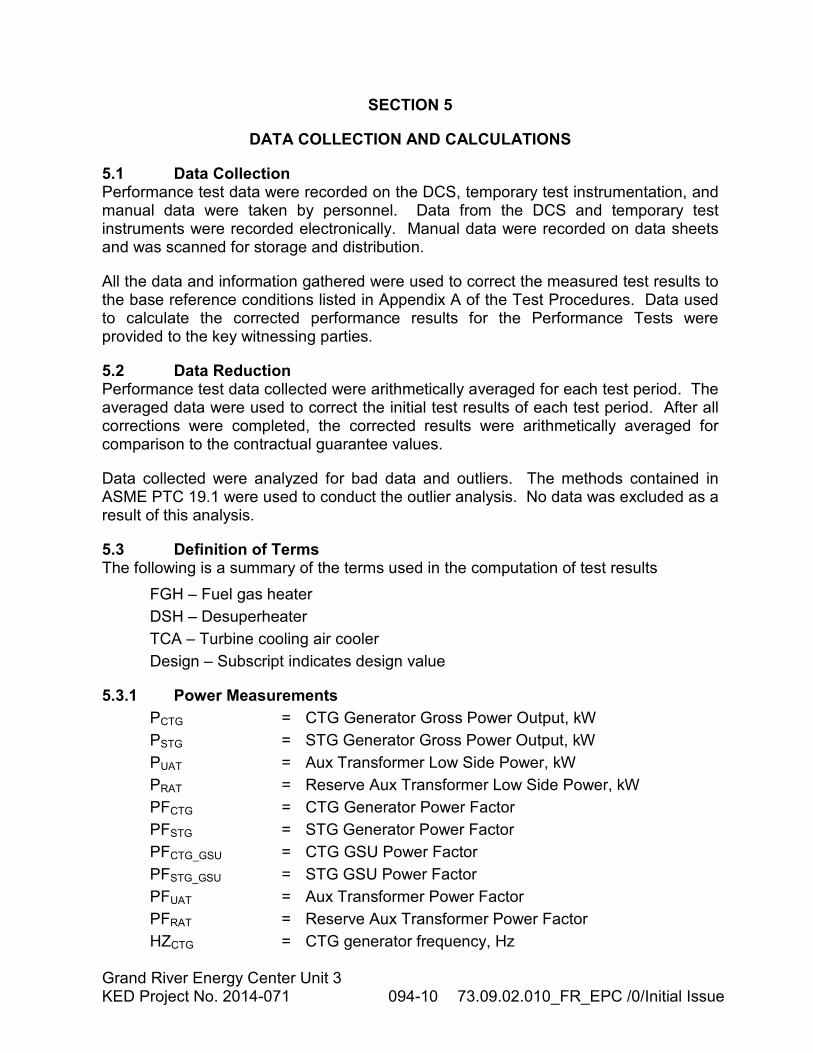
5.3 Definition of Terms The following is a summary of the terms used in the computation of test results
FGH – Fuel gas heater
DSH – Desuperheater
TCA – Turbine cooling air cooler
Design – Subscript indicates design value
5.3.1 Power Measurements
PCTG = CTG Generator Gross Power Output, kW
PSTG = STG Generator Gross Power Output, kW
PUAT = Aux Transformer Low Side Power, kW
PRAT = Reserve Aux Transformer Low Side Power, kW
PFCTG = CTG Generator Power Factor
PFSTG = STG Generator Power Factor
PFCTG_GSU = CTG GSU Power Factor
PFSTG_GSU = STG GSU Power Factor
PFUAT = Aux Transformer Power Factor
PFRAT = Reserve Aux Transformer Power Factor
HZCTG = CTG generator frequency, Hz
Grand River Energy Center Unit 3 KED Project No. 2014-071 094-11 73.09.02.010_FR_EPC /0/Initial Issue
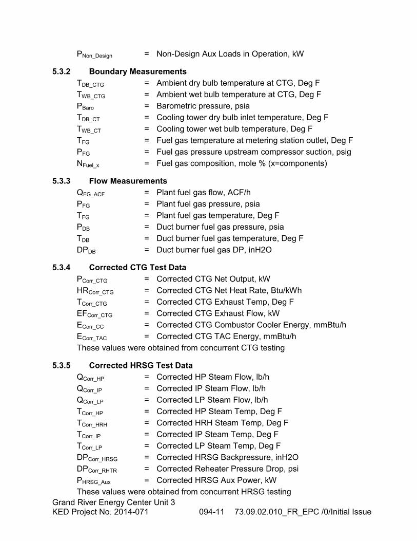
PNon_Design = Non-Design Aux Loads in Operation, kW
5.3.2 Boundary Measurements
TDB_CTG = Ambient dry bulb temperature at CTG, Deg F
TWB_CTG = Ambient wet bulb temperature at CTG, Deg F
PBaro = Barometric pressure, psia
TDB_CT = Cooling tower dry bulb inlet temperature, Deg F
TWB_CT = Cooling tower wet bulb temperature, Deg F
TFG = Fuel gas temperature at metering station outlet, Deg F
PFG = Fuel gas pressure upstream compressor suction, psig
NFuel_x = Fuel gas composition, mole % (x=components)
5.3.3 Flow Measurements
QFG_ACF = Plant fuel gas flow, ACF/h
PFG = Plant fuel gas pressure, psia
TFG = Plant fuel gas temperature, Deg F
PDB = Duct burner fuel gas pressure, psia
TDB = Duct burner fuel gas temperature, Deg F
DPDB = Duct burner fuel gas DP, inH2O
5.3.4 Corrected CTG Test Data
PCorr_CTG = Corrected CTG Net Output, kW
HRCorr_CTG = Corrected CTG Net Heat Rate, Btu/kWh
TCorr_CTG = Corrected CTG Exhaust Temp, Deg F
EFCorr_CTG = Corrected CTG Exhaust Flow, kW
ECorr_CC = Corrected CTG Combustor Cooler Energy, mmBtu/h
ECorr_TAC = Corrected CTG TAC Energy, mmBtu/h
These values were obtained from concurrent CTG testing
5.3.5 Corrected HRSG Test Data
QCorr_HP = Corrected HP Steam Flow, lb/h
QCorr_IP = Corrected IP Steam Flow, lb/h
QCorr_LP = Corrected LP Steam Flow, lb/h
TCorr_HP = Corrected HP Steam Temp, Deg F
TCorr_HRH = Corrected HRH Steam Temp, Deg F
TCorr_IP = Corrected IP Steam Temp, Deg F
TCorr_LP = Corrected LP Steam Temp, Deg F
DPCorr_HRSG = Corrected HRSG Backpressure, inH2O
DPCorr_RHTR = Corrected Reheater Pressure Drop, psi
PHRSG_Aux = Corrected HRSG Aux Power, kW
These values were obtained from concurrent HRSG testing
Grand River Energy Center Unit 3 KED Project No. 2014-071 094-12 73.09.02.010_FR_EPC /0/Initial Issue
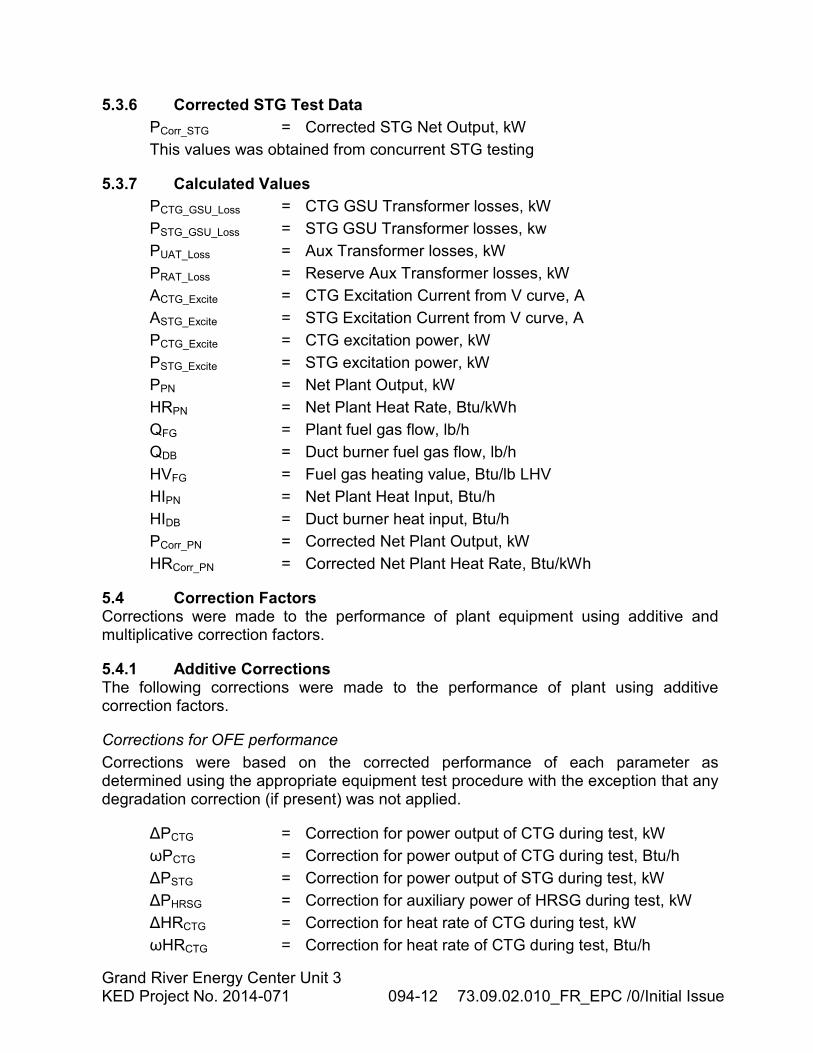
5.3.6 Corrected STG Test Data
PCorr_STG = Corrected STG Net Output, kW
This values was obtained from concurrent STG testing
5.3.7 Calculated Values
PCTG_GSU_Loss = CTG GSU Transformer losses, kW
PSTG_GSU_Loss = STG GSU Transformer losses, kw
PUAT_Loss = Aux Transformer losses, kW
PRAT_Loss = Reserve Aux Transformer losses, kW
ACTG_Excite = CTG Excitation Current from V curve, A
ASTG_Excite = STG Excitation Current from V curve, A
PCTG_Excite = CTG excitation power, kW
PSTG_Excite = STG excitation power, kW
PPN = Net Plant Output, kW
HRPN = Net Plant Heat Rate, Btu/kWh
QFG = Plant fuel gas flow, lb/h
QDB = Duct burner fuel gas flow, lb/h
HVFG = Fuel gas heating value, Btu/lb LHV
HIPN = Net Plant Heat Input, Btu/h
HIDB = Duct burner heat input, Btu/h
PCorr_PN = Corrected Net Plant Output, kW
HRCorr_PN = Corrected Net Plant Heat Rate, Btu/kWh
5.4 Correction Factors Corrections were made to the performance of plant equipment using additive and multiplicative correction factors.
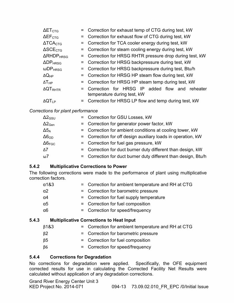
5.4.1 Additive Corrections The following corrections were made to the performance of plant using additive correction factors.
Corrections for OFE performance
Corrections were based on the corrected performance of each parameter as determined using the appropriate equipment test procedure with the exception that any degradation correction (if present) was not applied.
∆PCTG = Correction for power output of CTG during test, kW
ωPCTG = Correction for power output of CTG during test, Btu/h
∆PSTG = Correction for power output of STG during test, kW
∆PHRSG = Correction for auxiliary power of HRSG during test, kW
∆HRCTG = Correction for heat rate of CTG during test, kW
ωHRCTG = Correction for heat rate of CTG during test, Btu/h
Grand River Energy Center Unit 3 KED Project No. 2014-071 094-13 73.09.02.010_FR_EPC /0/Initial Issue
∆ETCTG = Correction for exhaust temp of CTG during test, kW
∆EFCTG = Correction for exhaust flow of CTG during test, kW
∆TCACTG = Correction for TCA cooler energy during test, kW
∆SCECTG = Correction for steam cooling energy during test, kW
∆RHDPHRSG = Correction for HRSG RHTR pressure drop during test, kW
∆DPHRSG = Correction for HRSG backpressure during test, kW
ωDPHRSG = Correction for HRSG backpressure during test, Btu/h
ΔQHP = Correction for HRSG HP steam flow during test, kW
ΔTHP = Correction for HRSG HP steam temp during test, kW
ΔQTRHTR = Correction for HRSG IP added flow and reheater
temperature during test, kW
ΔQTLP = Correction for HRSG LP flow and temp during test, kW
Corrections for plant performance
∆2GSU = Correction for GSU Losses, kW
∆2Gen = Correction for generator power factor, kW
∆5A = Correction for ambient conditions at cooling tower, kW
∆6OD = Correction for off design auxiliary loads in operation, kW
∆6FGC = Correction for fuel gas pressure, kW
Δ7 = Correction for duct burner duty different than design, kW
ω7 = Correction for duct burner duty different than design, Btu/h
5.4.2 Multiplicative Corrections to Power
The following corrections were made to the performance of plant using multiplicative correction factors.
α1&3 = Correction for ambient temperature and RH at CTG
α2 = Correction for barometric pressure
α4 = Correction for fuel supply temperature
α5 = Correction for fuel composition
α6 = Correction for speed/frequency
5.4.3 Multiplicative Corrections to Heat Input
β1&3 = Correction for ambient temperature and RH at CTG
β2 = Correction for barometric pressure
β5 = Correction for fuel composition
β6 = Correction for speed/frequency
5.4.4 Corrections for Degradation
No corrections for degradation were applied. Specifically, the OFE equipment corrected results for use in calculating the Corrected Facility Net Results were calculated without application of any degradation corrections.
Grand River Energy Center Unit 3 KED Project No. 2014-071 094-14 73.09.02.010_FR_EPC /0/Initial Issue
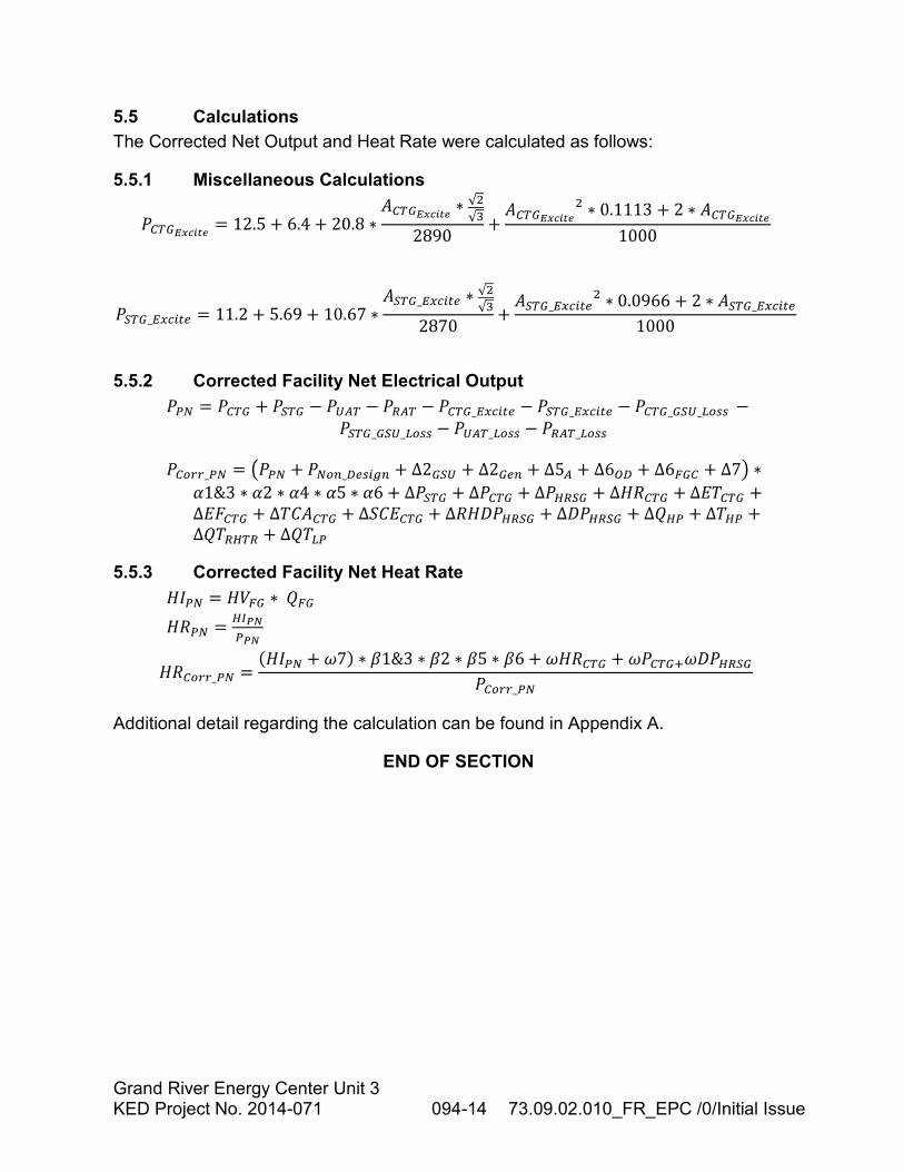
5.5 Calculations
The Corrected Net Output and Heat Rate were calculated as follows:
5.5.1 Miscellaneous Calculations
�������� != 12.5 + 6.4 + 20.8 ∗
+������� !∗ √�
√-
2890+
+������� !� ∗ 0.1113 + 2 ∗ +������� !
1000
����_0123�4 = 11.2 + 5.69 + 10.67 ∗+���_0123�4 ∗ √�
√-
2870+
+���_0123�4� ∗ 0.0966 + 2 ∗ +���_0123�4
1000
5.5.2 Corrected Facility Net Electrical Output
��� = ���� + ���� − �6 � − �� � − ����_0123�4 − ����_0123�4 − ����_��6_��77 −����_��6_��77 − �6 �_��77 − �� �_��77
���99_�� = :��� + ����_�473;� + ∆2��6 + ∆2�4� + ∆5 + ∆6=� + ∆6��� + ∆7> ∗?1&3 ∗ ?2 ∗ ?4 ∗ ?5 ∗ ?6 + ∆���� + ∆���� + ∆����� + ∆AB��� + ∆CD��� +∆CE��� + ∆DF+��� + ∆GFC��� + ΔBAI����� + ΔI����� + ∆��� + ∆D�� +∆�D���� + ∆�D��
5.5.3 Corrected Facility Net Heat Rate
AJ�� = AK�� ∗ ���
AB�� = �LMN
�MN
AB��99_�� =OAJ�� + P7Q ∗ R1&3 ∗ R2 ∗ R5 ∗ R6 + PAB��� + P����SPI�����
���99_��
Additional detail regarding the calculation can be found in Appendix A.
END OF SECTION
Grand River Energy Center Unit 3 KED Project No. 2014-071 094-15 73.09.02.010_FR_EPC /0/Initial Issue
SECTION 6
TEST RESULTS AND CONCLUSIONS
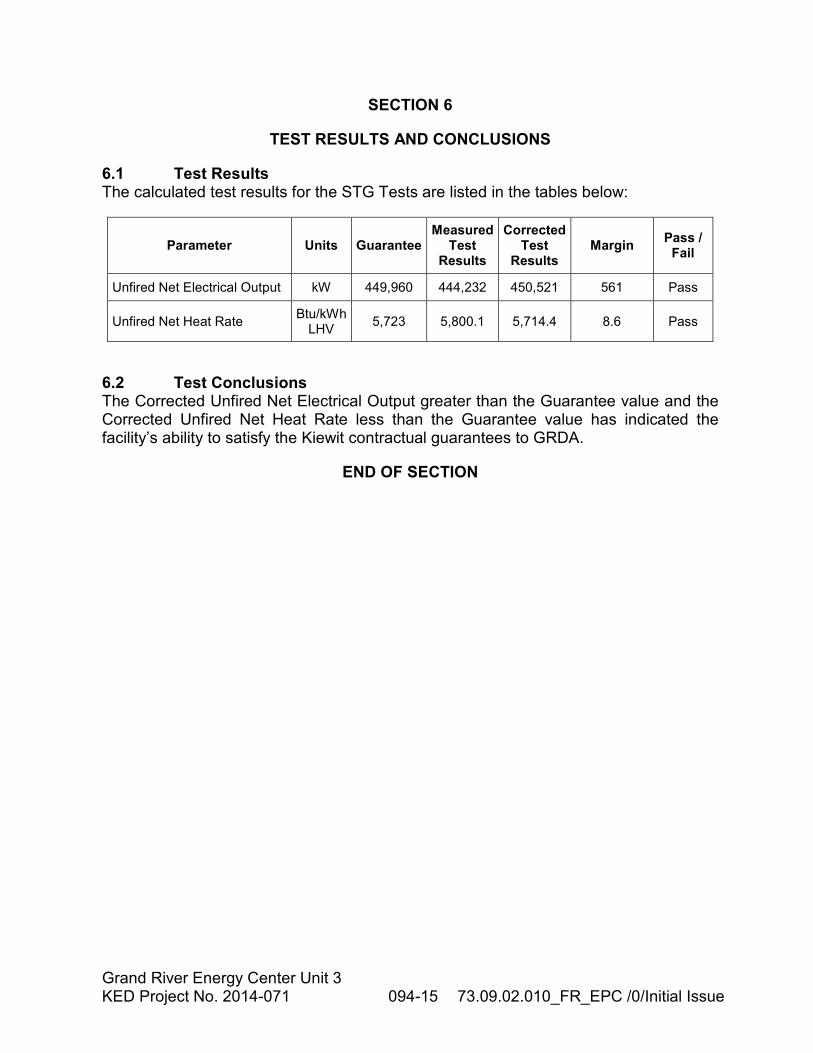
6.1 Test Results The calculated test results for the STG Tests are listed in the tables below:
Parameter Units Guarantee Measured
Test Results
Corrected Test
Results Margin
Pass / Fail
Unfired Net Electrical Output kW 449,960 444,232 450,521 561 Pass
Unfired Net Heat Rate Btu/kWh
LHV 5,723 5,800.1 5,714.4 8.6 Pass
6.2 Test Conclusions The Corrected Unfired Net Electrical Output greater than the Guarantee value and the Corrected Unfired Net Heat Rate less than the Guarantee value has indicated the facility’s ability to satisfy the Kiewit contractual guarantees to GRDA.
END OF SECTION


![Katie Dellaquila Jeremy Nelson Khiem Tong. Project Overview [KED] Multidisciplinary Aspects [KED] Motivation (Similar Products) [KED] System Schematic](https://img.pdfslide.net/doc/110x75/56649d2f5503460f94a0736b/katie-dellaquila-jeremy-nelson-khiem-tong-project-overview-ked-multidisciplinary.jpg)