Embed Size (px)
DESCRIPTION
LEYBOLD
Citation preview

06/06-W97-Web
Instruction sheet 735 3101
Industrial frequency converter 400 V (735 3101)
Safety notes The device complies with the safety requirements for electrical measuring, control and laboratory equipment in accordance with DIN EN 61010 part 1 (IEC 1010). It is intended for operation in dry rooms which are suitable for electrical equipment and devices. The safety of the davice is not guaranteed if the device is improperly used or carelessly handled. The device may only be operated by persons who are able to identify shock hazard and to take safety precautions. If it has to be assumed that safe operation is no longer possible (e.g. in the case of visible damage), shut the device down immedi-ately. When putting the device into operation for the first time: • Check whether the value for the mains voltage indicated on the rating plate agrees with the local value. • Read the instruction sheet of the device carefully and keep to the instructions it in every respect. Before putting the device into operation: • Examine the housing for damage. In case of malfunction or visible damage shut the device down and make sure that it is not used inadvertently. On every operation: • Connect the device only to socket-outlets with grounded neutral wire. • Never exceed the maximum permissible input values. • Use only safety connecting leads in the experiment setup.
Examine the connecting leads, test leads and probes for defective insulation and bare wires. • Replace a defective fuse only with a fuse that corresponds to the original value (see fuse plate). • Never short the fuse or the fuse holder. • Always keep the ventilation slots of the housing free in order to ensure sufficient air circulation for cooling the internal components. • Keep metallic objects, foreign matter and water away from the ventilation slots. • Do not put the device into operation if objects of that kind have got into the interior of the device. • Allow only skilled persons to open the device. • The device must not be subjected to strong shocks. • Strictly observe the warnings on the device and in the instruction sheet. • Do not perform measurements with a grounded oscilloscope. Always use an isolation amplifier. A hazardous-contact voltage, which is not isolated from the supply, is applied to the safety sockets. The voltage supply can only be switched off by means of the mains switch, not by pressing the STOP/RESET key. However, the capacitor in the DC link carries a hazardous-contact voltage for up to 4 minutes after switching off. • Establish a PE connection to the machine. • Change the experiment setup only if no voltage is applied (switch of by means of the mains switch).

Instruction sheet 735 3101 Seite 2/4
LD Didactic GmbH . Leyboldstrasse 1 . D-50354 Huerth / Germany . Phone (02233) 604-0 . Fax (02233) 604-222 . e-mail: [email protected] by LD Didactic GmbH Printed in the Federal Republic of Germany Technical alterations reserved
1 Description The industrial frequency converter 400 V is an industrial, microprocessor-based frequency converter with DC link, mounted in an experiment plate which is particularly suited for didactic purposes. All measuring and connecting points are guided to 4 mm sockets which are located within a block diagram. Details regarding programming are found in the Siemens product manuals for the G120 und CU240. A frequency converter is an electronic device for continuously controlling the speed of asynchronous machines. In order to make this possible, the three-phase mains voltage first has to be converted into a direct voltage, which is then converted into a three-phase voltage of vari-able amplitude and frequency. Appropriate machines for connection to the converter are squirrel-cage motors or slipring motors of the power classes
0.3 kW and 1.0 kW with a nominal voltage of 400 V / 690 V. 2 Technical data rated output / kilowatt (kW) 1.1 kW
rated output / in Horse Power (HP) 1.5 hp
Input voltage / minimum 380 V
Input voltage / maximum 480 V
Line frequency 50 Hz
efficiency eta 95
Rated Input Current 3.9 A
Output current / for constant torque / rated value 3.1 A
Phase number / of the outputs 3
Electrical output frequency / maximum 650 Hz
Protection class IP IP 20
(3)
Digital Outputs
(2)
Connection of chopper resistor and measurement of intermediate circuit voltage
(1)
Outputs 3 x 400V
(11)
Connection for
Temperature sensor (12)
Connection for
Protection Earth
(7)
Digital
Inputs
(9)
Analog
Ground
(10)
Digital Ground
(8)
Analog
Output
(4) Potentiometer
(6) Analog
Input
(5)
switch
Seite 3/4 Instruction sheet 735 3101
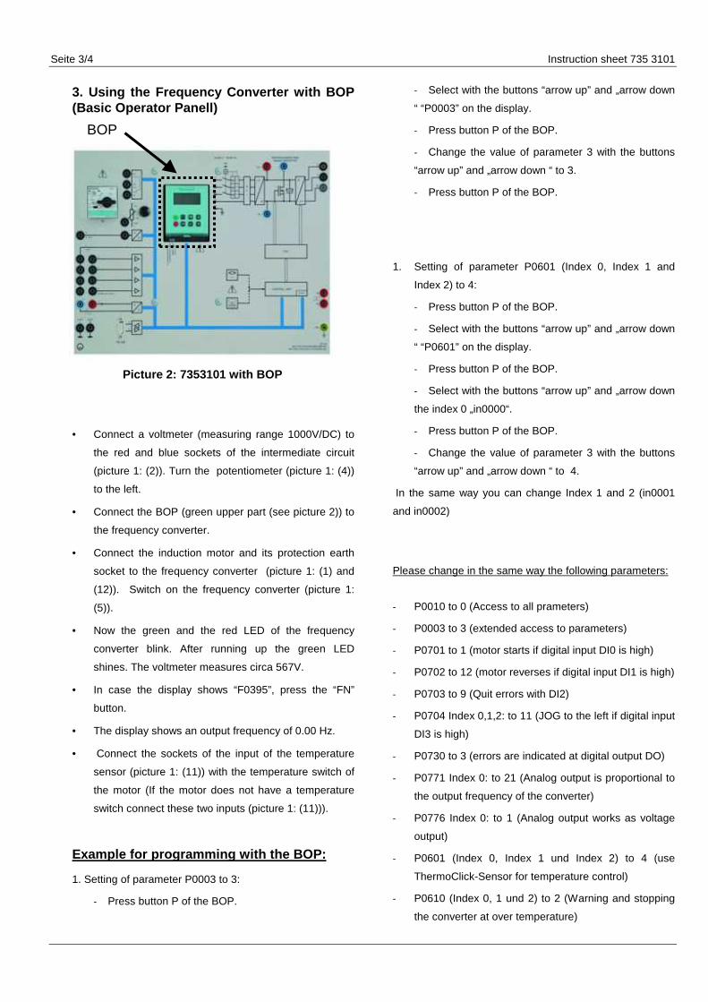
3. Using the Frequency Converter with BOP (Basic Operator Panell)
Picture 2: 7353101 with BOP
• Connect a voltmeter (measuring range 1000V/DC) to
the red and blue sockets of the intermediate circuit
(picture 1: (2)). Turn the potentiometer (picture 1: (4))
to the left.
• Connect the BOP (green upper part (see picture 2)) to
the frequency converter.
• Connect the induction motor and its protection earth
socket to the frequency converter (picture 1: (1) and
(12)). Switch on the frequency converter (picture 1:
(5)).
• Now the green and the red LED of the frequency
converter blink. After running up the green LED
shines. The voltmeter measures circa 567V.
• In case the display shows “F0395”, press the “FN”
button.
• The display shows an output frequency of 0.00 Hz.
• Connect the sockets of the input of the temperature
sensor (picture 1: (11)) with the temperature switch of
the motor (If the motor does not have a temperature
switch connect these two inputs (picture 1: (11))).
Example for programming with the BOP:
1. Setting of parameter P0003 to 3:
- Press button P of the BOP.
- Select with the buttons “arrow up” and „arrow down
“ “P0003” on the display.
- Press button P of the BOP.
- Change the value of parameter 3 with the buttons
“arrow up” and „arrow down “ to 3.
- Press button P of the BOP.
1. Setting of parameter P0601 (Index 0, Index 1 and
Index 2) to 4:
- Press button P of the BOP.
- Select with the buttons “arrow up” and „arrow down
“ “P0601” on the display.
- Press button P of the BOP.
- Select with the buttons “arrow up” and „arrow down
the index 0 „in0000“.
- Press button P of the BOP.
- Change the value of parameter 3 with the buttons
“arrow up” and „arrow down “ to 4.
In the same way you can change Index 1 and 2 (in0001
and in0002)
Please change in the same way the following parameters:
- P0010 to 0 (Access to all prameters)
- P0003 to 3 (extended access to parameters)
- P0701 to 1 (motor starts if digital input DI0 is high)
- P0702 to 12 (motor reverses if digital input DI1 is high)
- P0703 to 9 (Quit errors with DI2)
- P0704 Index 0,1,2: to 11 (JOG to the left if digital input
DI3 is high)
- P0730 to 3 (errors are indicated at digital output DO)
- P0771 Index 0: to 21 (Analog output is proportional to
the output frequency of the converter)
- P0776 Index 0: to 1 (Analog output works as voltage
output)
- P0601 (Index 0, Index 1 und Index 2) to 4 (use
ThermoClick-Sensor for temperature control)
- P0610 (Index 0, 1 und 2) to 2 (Warning and stopping
the converter at over temperature)
BOP

Instruction sheet 735 3101 Seite 4/4
LD Didactic GmbH . Leyboldstrasse 1 . D-50354 Huerth / Germany . Phone (02233) 604-0 . Fax (02233) 604-222 . e-mail: [email protected] by LD Didactic GmbH Printed in the Federal Republic of Germany Technical alterations reserved
Saving the parameters. Please set: - Parameter P0010 to 1
- Parameter P3900 to 1
- You can see „bUSY“ until the saving is finished
-
Testing the changing of the parameters • Test DI0 and AI1: Connect the potentiometer (picture
1: (4)) to the analog input (picture 1: (6)).
• Connect +24V to the digital input DI0 (picture 1: (7)).
The fan starts and you can hear the switching
frequency of the converter.
• Now you can change the output frequency oft the
converter with the potentiometer (picture 1: (4)). The
motor turns to the right.
• After pressing the button „FN“ for circa 2s the
intermidiate circuit voltage (circa 567 V) is shown at
the display (indicated by „d“). By pressing the button
„FN“ you can see other values (output frequency, out
voltage ((indicated by „o“) and so on).
• Turning the potentiometer completely to the right. By
pressing the button „FN“ you can see at the display
the output voltage 400V and the output frequency
50Hz .
• Test AO0: Connecting the analog output (picture 1:
(7)) to a voltmeter. The analog output AO0 is
proportional to the required value of the output
frequency and changes with thepotentiometer (turning
the potentiometer completely to the left -> 0V, turning
completely to the right -> 10V)
• Test DI1: Connect +24V to the digital input DI1
(picture 1: (7)). The motor turns to the left.
• Test DI3: Disconnect DI0 and DI1 from +24V. Connect
+24V to the digital input DI3 (picture 1: (7)). The
motor runs with a fixed frequency (- 5Hz), that is not
influenced by the potentiometer.
• Test of temperature control and digital output:.
Connect +24V to the digital input DI0 (picture 1: (7)) to
start the motor. Connect the plugs 20 and 19 of the
digital output (picture 1: (3)) with a ohmmeter. The
ohmmeter indicates “0 Ohm”.
• Disconnect the sockets 14 and 15 of
connection for Temperature sensor (picture
1: (11)). The motor stops after 2s. The
ohmmeter indicates “open circuit”.
• Test DI2: Connect +24V to the digital input
DI2 (picture 1: (7)). The error of the over
temperature disappears. The ohmmeter
indicates “0 Ohm”.