Embed Size (px)
Citation preview
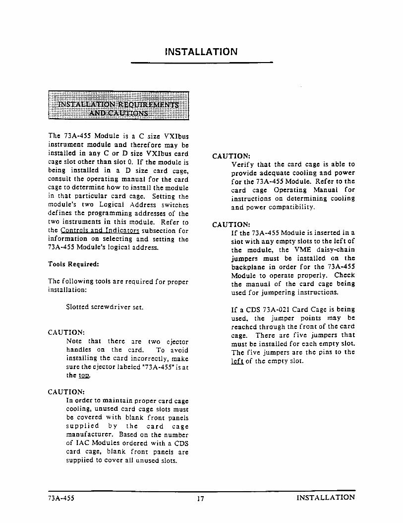
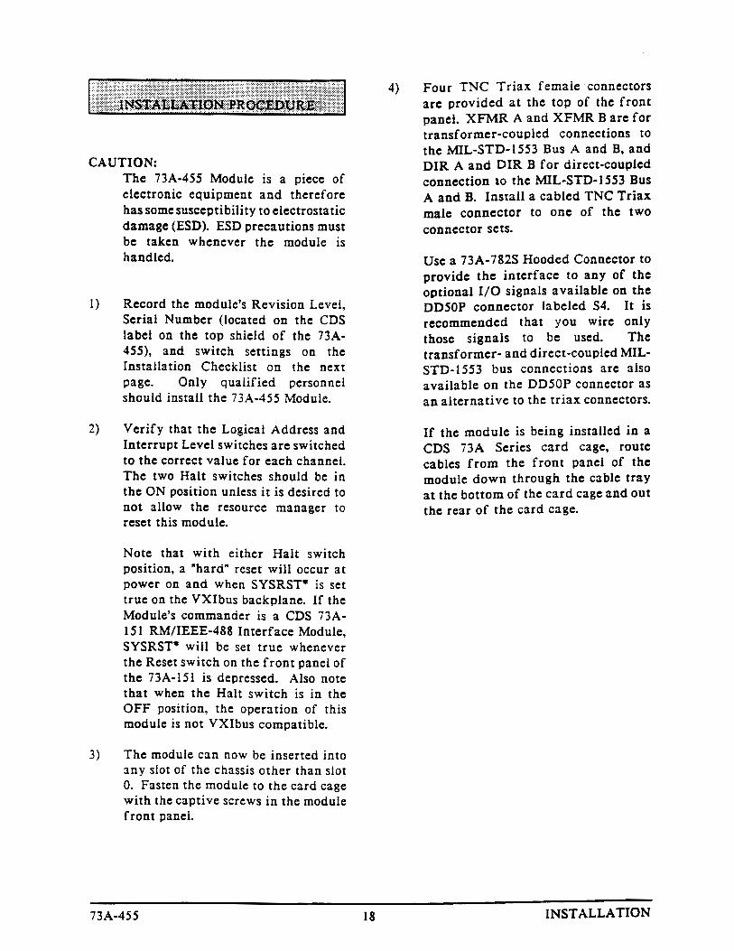
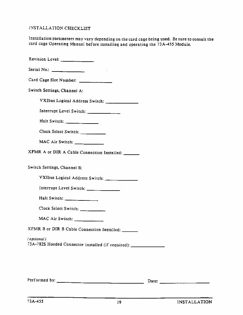
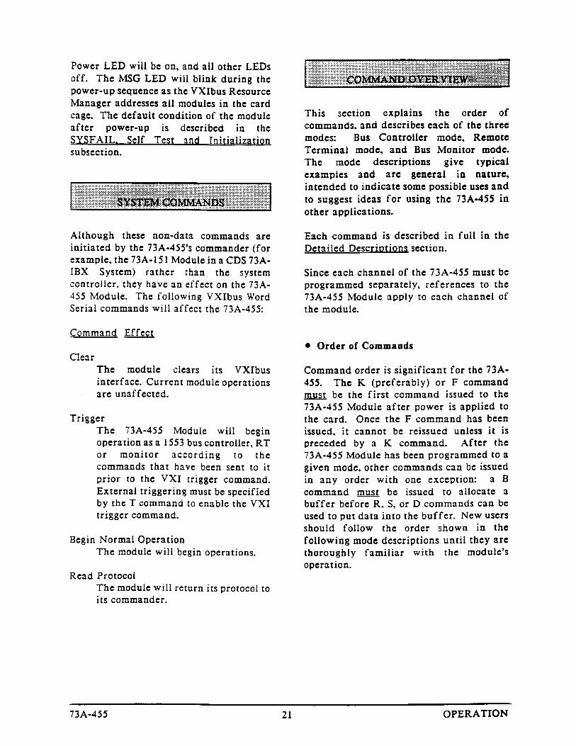
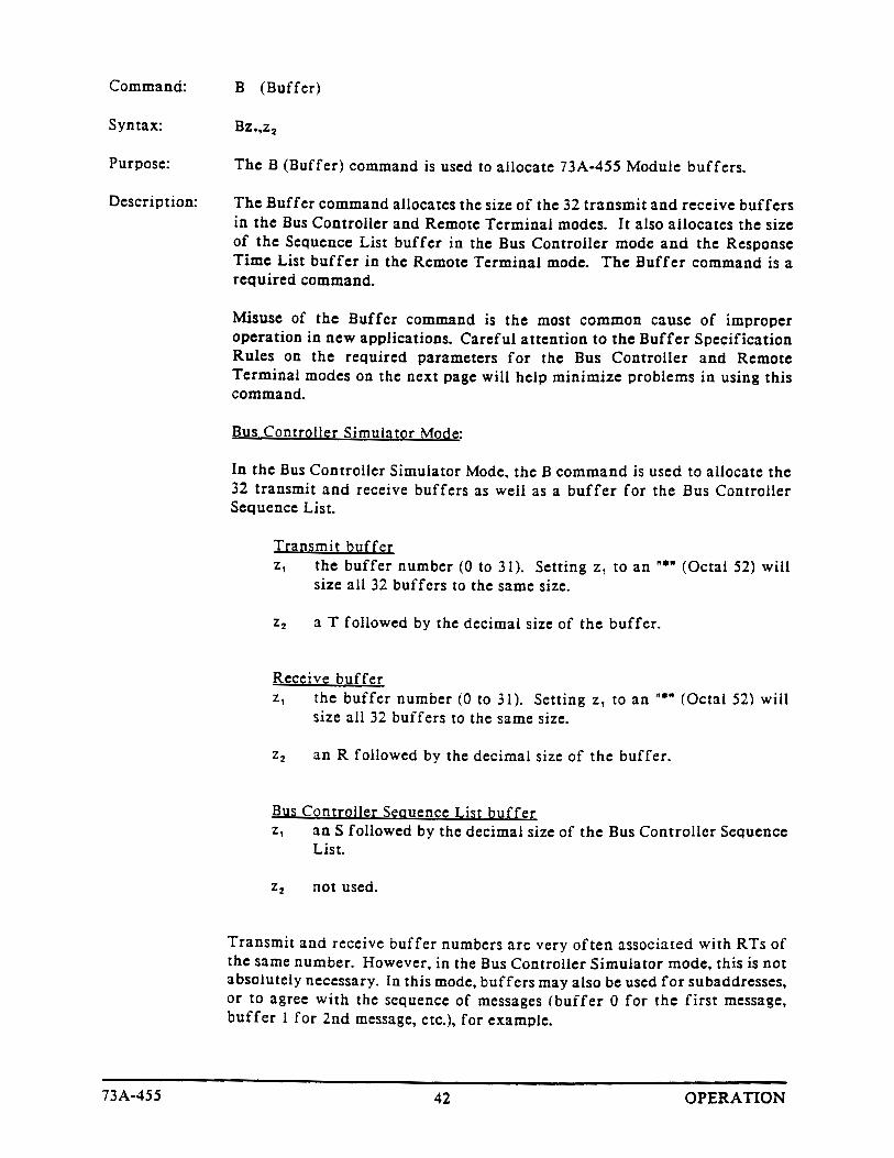
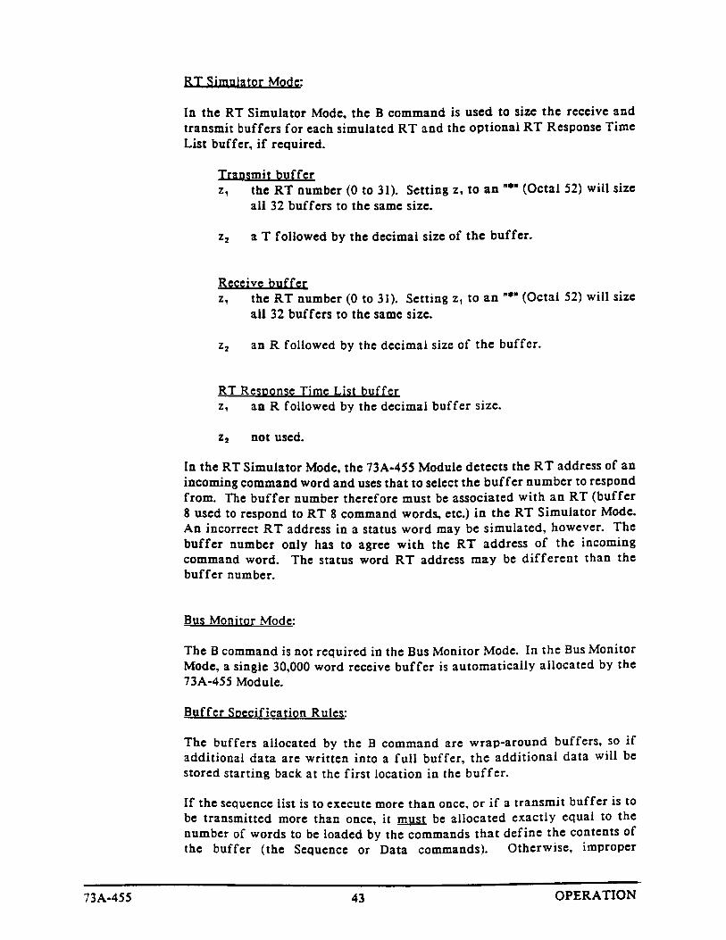
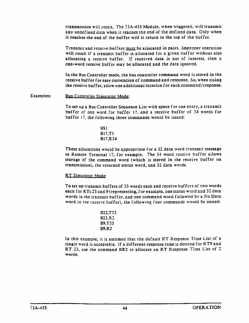
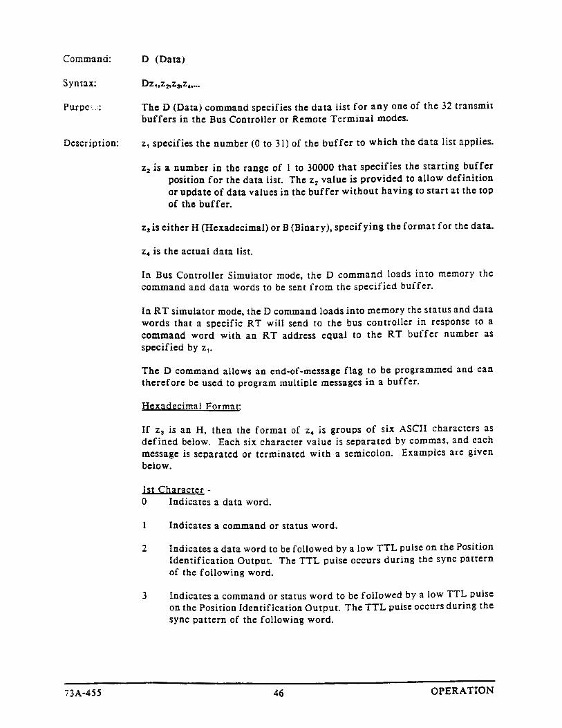
User Manual
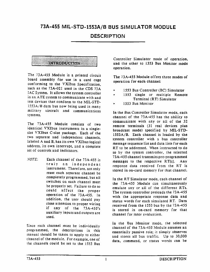
73A-455MIL-STD-1553A/B Bus Simulator Module
070-9136-02
This document applies for firmware version 1.00and above.

Copyright � Tektronix, Inc. All rights reserved.
Tektronix products are covered by U.S. and foreign patents, issued and pending. Information in this publication supercedesthat in all previously published material. Specifications and price change privileges reserved.
Printed in the U.S.A.
Tektronix, Inc., P.O. Box 1000, Wilsonville, OR 97070–1000
TEKTRONIX and TEK are registered trademarks of Tektronix, Inc.

WARRANTY
Tektronix warrants that this product will be free from defects in materials and workmanship for a period of three(3) years from the date of shipment. If any such product proves defective during this warranty period, Tektronix,at its option, either will repair the defective product without charge for parts and labor, or will provide areplacement in exchange for the defective product.
In order to obtain service under this warranty, Customer must notify Tektronix of the defect before the expirationof the warranty period and make suitable arrangements for the performance of service. Customer shall beresponsible for packaging and shipping the defective product to the service center designated by Tektronix, withshipping charges prepaid. Tektronix shall pay for the return of the product to Customer if the shipment is to alocation within the country in which the Tektronix service center is located. Customer shall be responsible forpaying all shipping charges, duties, taxes, and any other charges for products returned to any other locations.
This warranty shall not apply to any defect, failure or damage caused by improper use or improper or inadequatemaintenance and care. Tektronix shall not be obligated to furnish service under this warranty a) to repair damageresulting from attempts by personnel other than Tektronix representatives to install, repair or service the product;b) to repair damage resulting from improper use or connection to incompatible equipment; or c) to service aproduct that has been modified or integrated with other products when the effect of such modification orintegration increases the time or difficulty of servicing the product.
THIS WARRANTY IS GIVEN BY TEKTRONIX WITH RESPECT TO THIS PRODUCT IN LIEU OFANY OTHER WARRANTIES, EXPRESSED OR IMPLIED. TEKTRONIX AND ITS VENDORSDISCLAIM ANY IMPLIED WARRANTIES OF MERCHANTABILITY OR FITNESS FOR APARTICULAR PURPOSE. TEKTRONIX’ RESPONSIBILITY TO REPAIR OR REPLACE DEFECTIVEPRODUCTS IS THE SOLE AND EXCLUSIVE REMEDY PROVIDED TO THE CUSTOMER FORBREACH OF THIS WARRANTY. TEKTRONIX AND ITS VENDORS WILL NOT BE LIABLE FOR ANYINDIRECT, SPECIAL, INCIDENTAL, OR CONSEQUENTIAL DAMAGES IRRESPECTIVE OFWHETHER TEKTRONIX OR THE VENDOR HAS ADVANCE NOTICE OF THE POSSIBILITY OFSUCH DAMAGES.
EC Declaration of Conformity
We
Tektronix Holland N.V.Marktweg 73A8444 AB HeerenveenThe Netherlands
declare under sole responsibility that the
73A-455 and all options
meets the intent of Directive 89/336/EEC for Electromagnetic Compatibility.Compliance was demonstrated to the following specifications as listed in the OfficialJournal of the European Communities:
EN 55011 Class A Radiated and Conducted Emissions
EN 50081-1 Emissions:
EN 60555-2 AC Power Line Harmonic Emissions
EN 50082-1 Immunity:
IEC 801-2 Electrostatic Discharge ImmunityIEC 801-3 RF Electromagnetic Field ImmunityIEC 801-4 Electrical Fast Transient/Burst ImmunityIEC 801-5 Power Line Surge Immunity
To ensure compliance with EMC requirements only high quality shielded cables havinga reliable, continuous outer shield (braid & foil) which has low impedance connectionsto shielded connector housings at both ends should be connected to this product.
���������
���� �� ��������
����������
�+1/,"2!1',+ �� � � � � � � � � � � � � � � � � � � � � � � � � � � � � � � � � � � � � � � � � � � � � � � � � � � � � � � � � � � � � � � � � � � � � � � � � �
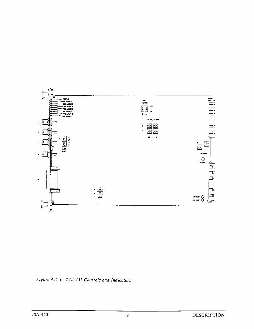
�,+1/,)0 �+" �+"'! 1,/0 � � � � � � � � � � � � � � � � � � � � � � � � � � � � � � � � � � � � � � � � � � � � � � � � � � � � � � � � � � � � � � � �
���� ��2')18�+ �#01 �.2'-*#+1� � � � � � � � � � � � � � � � � � � � � � � � � � � � � � � � � � � � � � � � � � � � � � � � � � � � � � � � � � �
�),00 /6 �� � � � � � � � � � � � � � � � � � � � � � � � � � � � � � � � � � � � � � � � � � � � � � � � � � � � � � � � � � � � � � � � � � � � � � � � � � � � �
�������������� ��� � � � � � � � � � � � � � � � � � � � � � � � � � � � � � � � � � � � � � � � � � � � � � � � � � � � � � � � � � � � � � � � � �
�����������
�+01 )) 1',+ �#.2'/#*#+10 +" � 21',+0 � � � � � � � � � � � � � � � � � � � � � � � � � � � � � � � � � � � � � � � � � � � � � � � � � �
�+01 )) 1',+ �/,!#"2/# ��� � � � � � � � � � � � � � � � � � � � � � � � � � � � � � � � � � � � � � � � � � � � � � � � � � � � � � � � � � � � � � � � �
�+01 )) 1',+ �&#!()'01 ��� � � � � � � � � � � � � � � � � � � � � � � � � � � � � � � � � � � � � � � � � � � � � � � � � � � � � � � � � � � � � � � � � �
���������
�3#/3'#4 ��� � � � � � � � � � � � � � � � � � � � � � � � � � � � � � � � � � � � � � � � � � � � � � � � � � � � � � � � � � � � � � � � � � � � � � � � � � � �
�,4#/82- ��� � � � � � � � � � � � � � � � � � � � � � � � � � � � � � � � � � � � � � � � � � � � � � � � � � � � � � � � � � � � � � � � � � � � � � � � � � � �
�601#* �,** +"0 ��� � � � � � � � � � � � � � � � � � � � � � � � � � � � � � � � � � � � � � � � � � � � � � � � � � � � � � � � � � � � � � � � � �
�,** +" �3#/3'#4 ��� � � � � � � � � � � � � � � � � � � � � � � � � � � � � � � � � � � � � � � � � � � � � � � � � � � � � � � � � � � � � � � � � �
�/"#/ ,$ �,** +"0 ��� � � � � � � � � � � � � � � � � � � � � � � � � � � � � � � � � � � � � � � � � � � � � � � � � � � � � � � � � � � � �
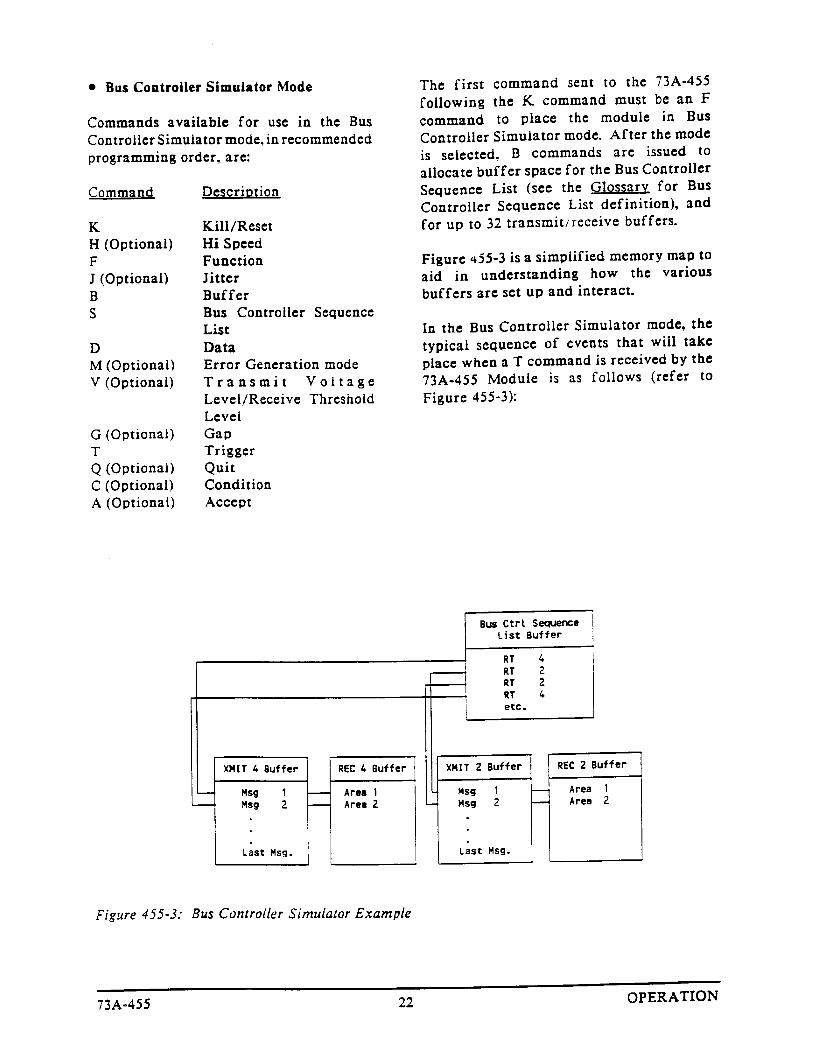
�20 �,+1/,))#/ �'*2) 1,/ �,"# ��� � � � � � � � � � � � � � � � � � � � � � � � � � � � � � � � � � � � � � � � � � � � � � � � � � � �
�#*,1# �#/*'+ ) �'*2) 1,/ �,"# ��� � � � � � � � � � � � � � � � � � � � � � � � � � � � � � � � � � � � � � � � � � � � � � � � � �
�20 �,+'1,/ �,"# ��� � � � � � � � � � � � � � � � � � � � � � � � � � � � � � � � � � � � � � � � � � � � � � � � � � � � � � � � � � � � � � �
�))8*,"# �,** +"0 ��� � � � � � � � � � � � � � � � � � � � � � � � � � � � � � � � � � � � � � � � � � � � � � � � � � � � � � � � � � � �
�//,/0 �� � � � � � � � � � � � � � � � � � � � � � � � � � � � � � � � � � � � � � � � � � � � � � � � � � � � � � � � � � � � � � � � � � � � � � � � � � � � � � �
�//,/ �#+#/ 1',+ �� � � � � � � � � � � � � � � � � � � � � � � � � � � � � � � � � � � � � � � � � � � � � � � � � � � � � � � � � � � � � � � �
�//,/ �#1#!1',+ �� � � � � � � � � � � � � � � � � � � � � � � � � � � � � � � � � � � � � � � � � � � � � � � � � � � � � � � � � � � � � � � � � �
�,** +" �&#!('+% �� � � � � � � � � � � � � � � � � � � � � � � � � � � � � � � � � � � � � � � � � � � � � � � � � � � � � � � � � � � � �
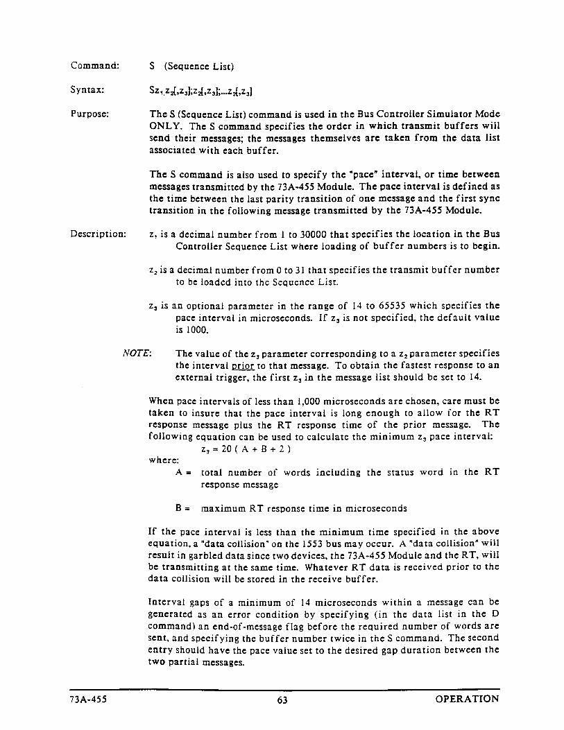
�,** +" �#0!/'-1',+0 �� � � � � � � � � � � � � � � � � � � � � � � � � � � � � � � � � � � � � � � � � � � � � � � � � � � � � � � � � � � � � � �
�,** +" �6+1 5 �� � � � � � � � � � � � � � � � � � � � � � � � � � � � � � � � � � � � � � � � � � � � � � � � � � � � � � � � � � � � � � �
�#1 ')#" �#0!/'-1',+0 � � � � � � � � � � � � � � � � � � � � � � � � � � � � � � � � � � � � � � � � � � � � � � � � � � � � � � � � � � � �
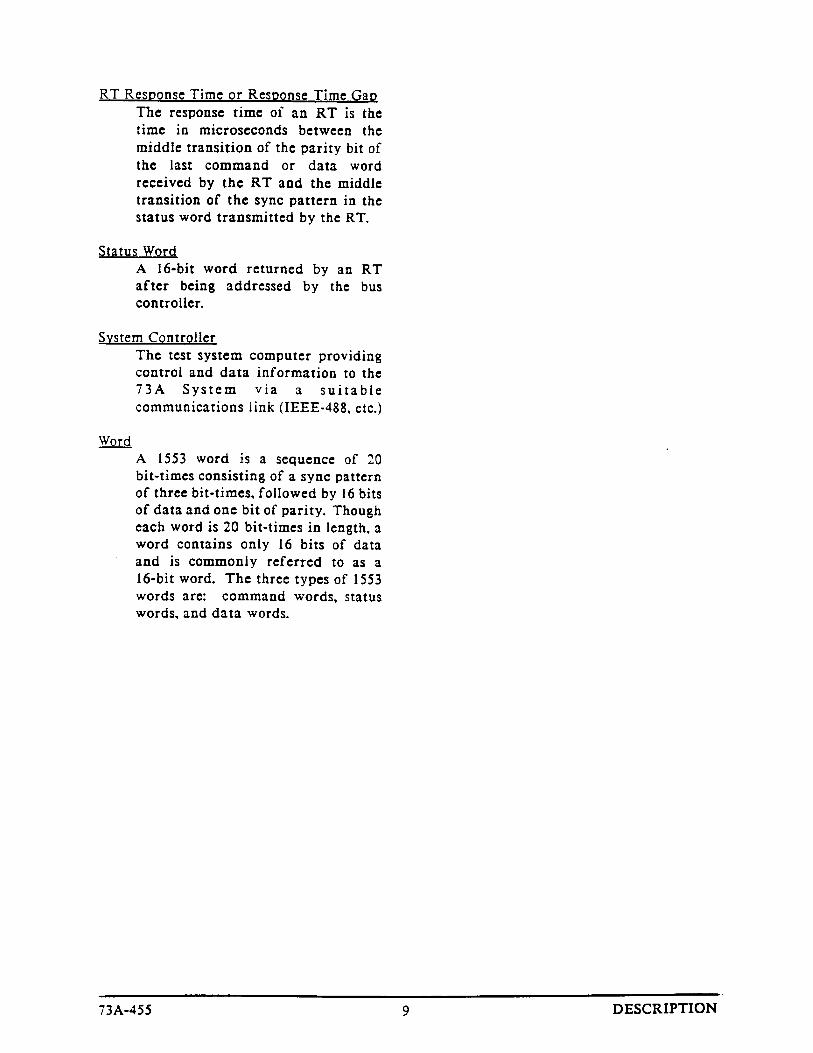
�������� �#)$ �#01� +" �+'1' )'7 1',+ �� � � � � � � � � � � � � � � � � � � � � � � � � � � � � � � � � � � � � � � � � � � � � � � � � � � �
�/,%/ **'+% �5 *-)#0 �� � � � � � � � � � � � � � � � � � � � � � � � � � � � � � � � � � � � � � � � � � � � � � � � � � � � � � � � � � � � � �
�#$'+'1',+ ,$ ����� �,** +"0 � � � � � � � � � � � � � � � � � � � � � � � � � � � � � � � � � � � � � � � � � � � � � � � � � � �
�/,%/ **'+% �5 *-)#0 '+ ����� � � � � � � � � � � � � � � � � � � � � � � � � � � � � � � � � � � � � � � � � � � � � � � � � �
����� � �����
��� �������
� ����
,,#*"'2 � ��� 0. �,#-�/'+* �� � � � � � � � � � � � � � � � � � � � � � � � � � � � � � � � � � � � � � � � � � � � � � � � � � � � � � �
,,#*"'2 � � �*,0/��0/,0/ �+**#!/'+*. ��� � � � � � � � � � � � � � � � � � � � � � � � � � � � � � � � � � � � � � � � � � � � � � � �
,,#*"'2 � � ��� 0. �(+..�-3 �� � � � � � � � � � � � � � � � � � � � � � � � � � � � � � � � � � � � � � � � � � � � � � � � � � � � � � � �
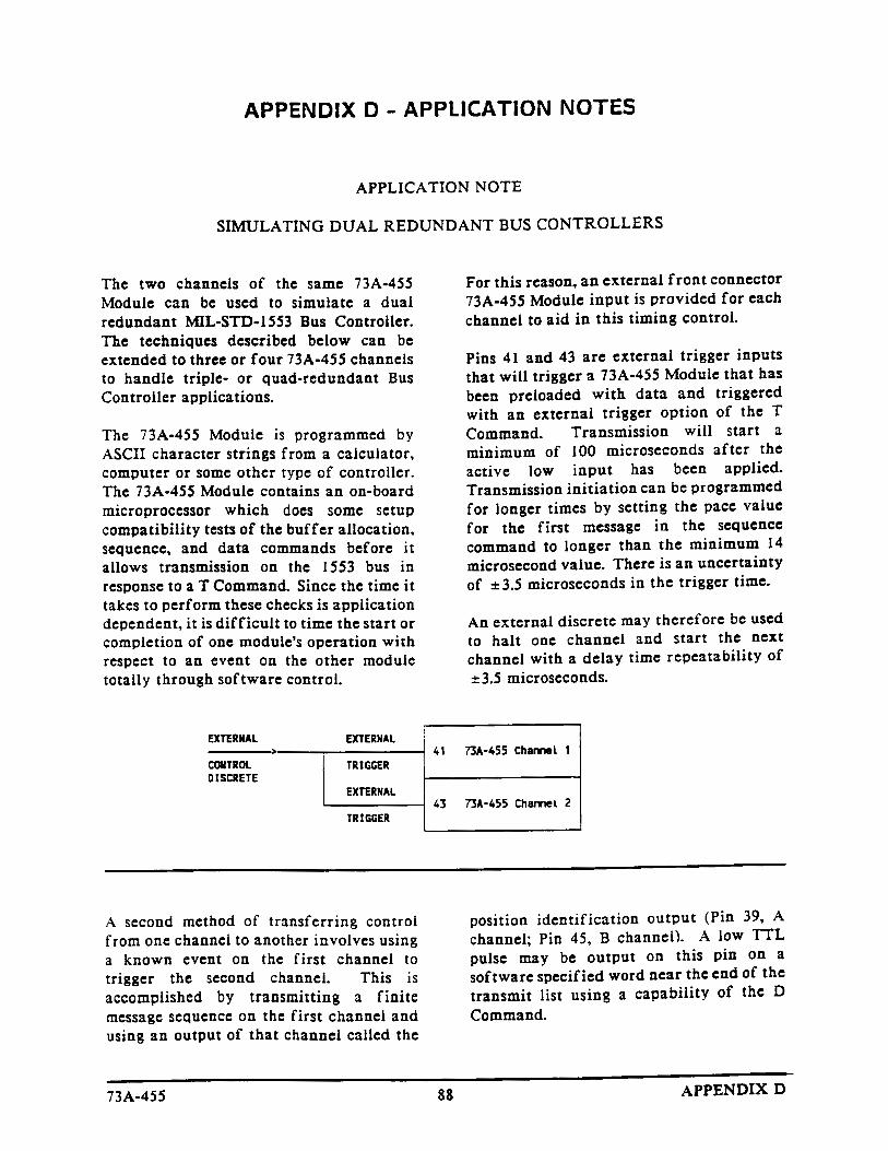
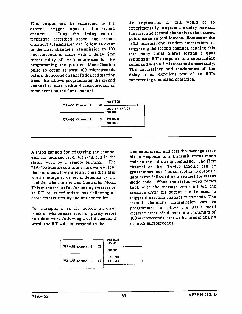
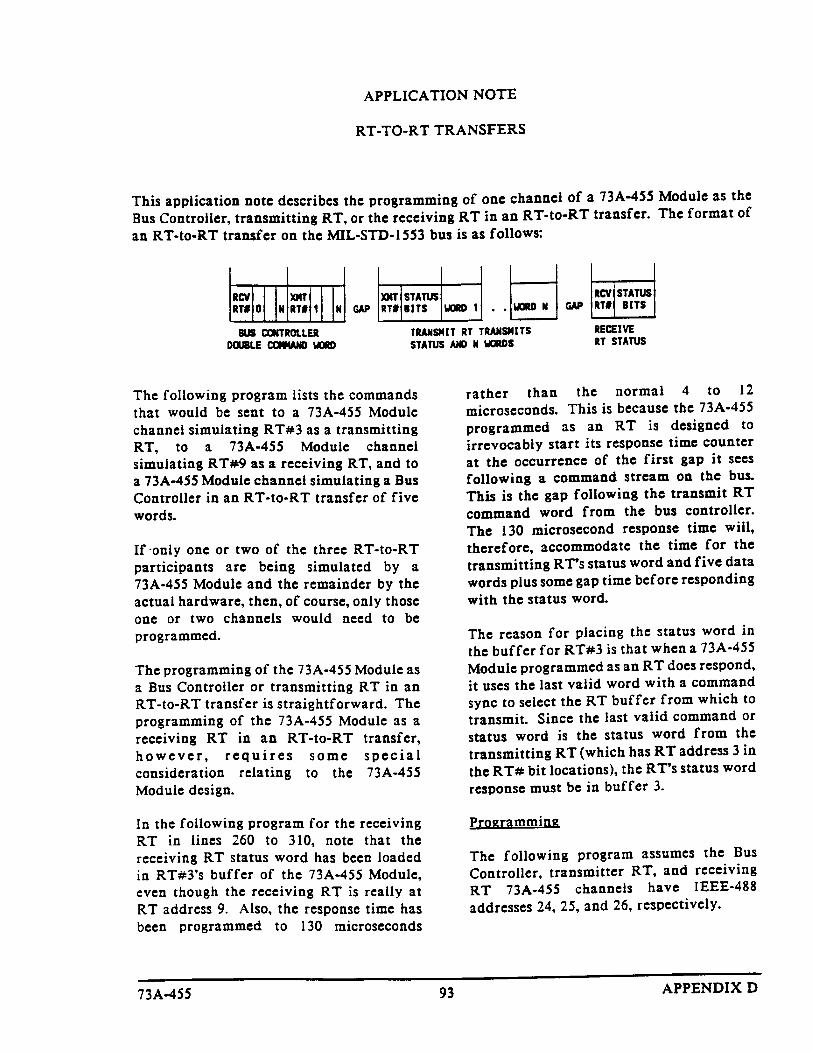
,,#*"'2 � � ,,('!�/'+* �+/#.
�')0(�/'*% �0�( �#"0*"�*/ �0. �+*/-+((#-. ��� � � � � � � � � � � � � � � � � � � � � � � � � � � � � � � � � � � � � � � �
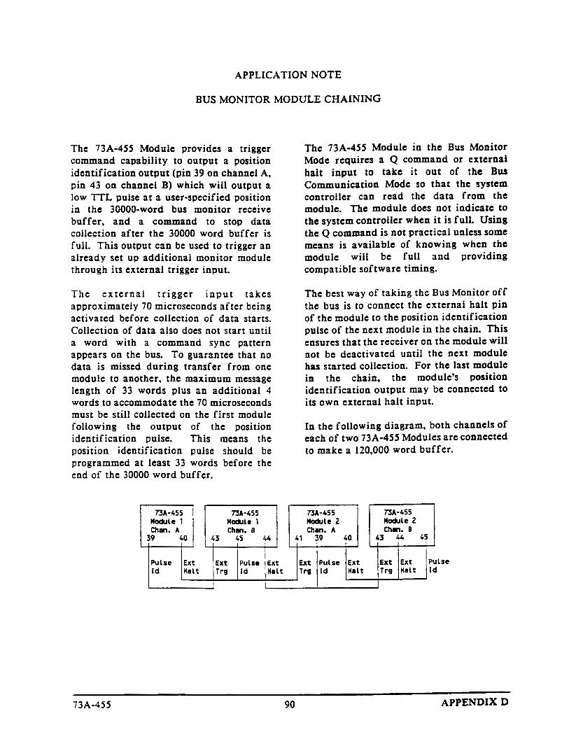
�0. �+*'/+- �+"0(# �&�'*'*% ��� � � � � � � � � � � � � � � � � � � � � � � � � � � � � � � � � � � � � � � � � � � � � � � � � � � � �
��4/+4�� �-�*.$#-. ��� � � � � � � � � � � � � � � � � � � � � � � � � � � � � � � � � � � � � � � � � � � � � � � � � � � � � � � � � � � � � � �
,,#*"'2 � � �#-$+-)�*!# �#-'$'!�/'+* ��� � � � � � � � � � � � � � � � � � � � � � � � � � � � � � � � � � � � � � � � � � � � � � � � �
,,#*"'2 � � �.#- �#-1'!# ��� � � � � � � � � � � � � � � � � � � � � � � � � � � � � � � � � � � � � � � � � � � � � � � � � � � � � � � � � � �
,,#*"'2 � � �,/'+* �� ���� � � � � � � � � � � � � � � � � � � � � � � � � � � � � � � � � � � � � � � � � � � � � � � � � � � � � � � � � � � � �
73A-455VX4469A ARINC 629 Communication Module User Manual iii
General Safety Summary
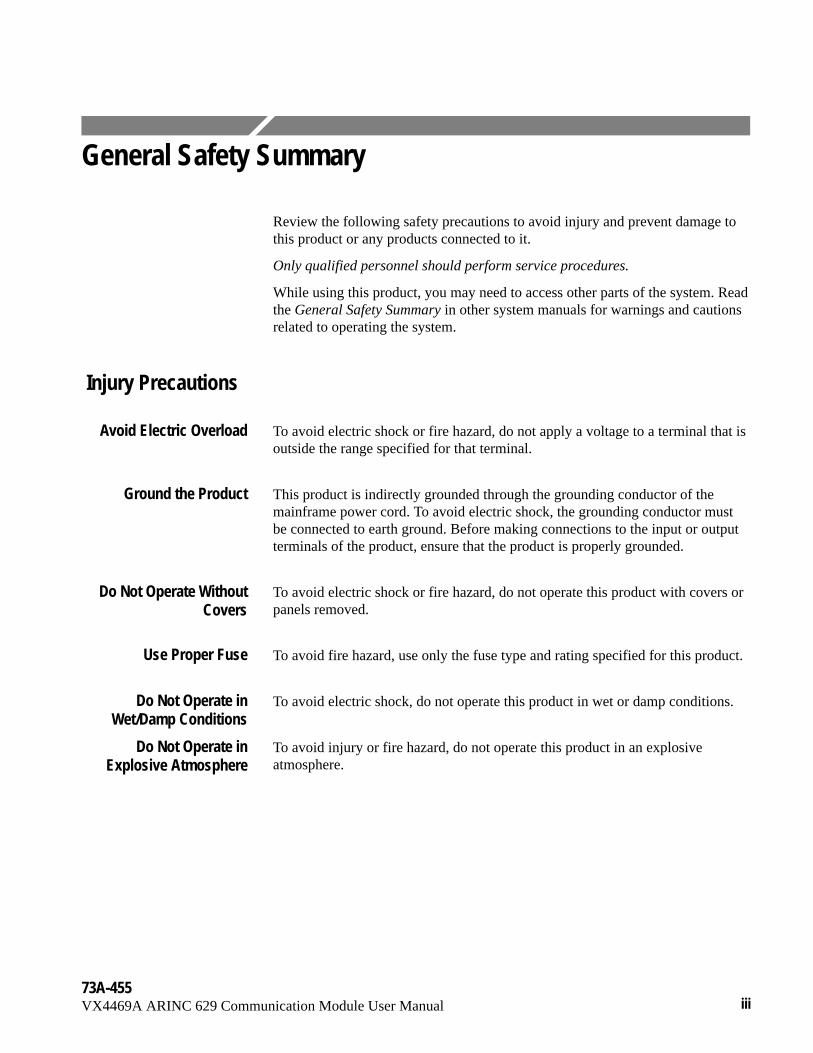
Review the following safety precautions to avoid injury and prevent damage tothis product or any products connected to it.
Only qualified personnel should perform service procedures.
While using this product, you may need to access other parts of the system. Readthe General Safety Summary in other system manuals for warnings and cautionsrelated to operating the system.
Injury Precautions
To avoid electric shock or fire hazard, do not apply a voltage to a terminal that isoutside the range specified for that terminal.
This product is indirectly grounded through the grounding conductor of themainframe power cord. To avoid electric shock, the grounding conductor mustbe connected to earth ground. Before making connections to the input or outputterminals of the product, ensure that the product is properly grounded.
To avoid electric shock or fire hazard, do not operate this product with covers orpanels removed.
To avoid fire hazard, use only the fuse type and rating specified for this product.
To avoid electric shock, do not operate this product in wet or damp conditions.
To avoid injury or fire hazard, do not operate this product in an explosiveatmosphere.
Avoid Electric Overload
Ground the Product
Do Not Operate WithoutCovers
Use Proper Fuse
Do Not Operate inWet/Damp Conditions
Do Not Operate inExplosive Atmosphere
General Safety Summary
iv73A-455
VX4469A ARINC 629 Communication Module User Manual
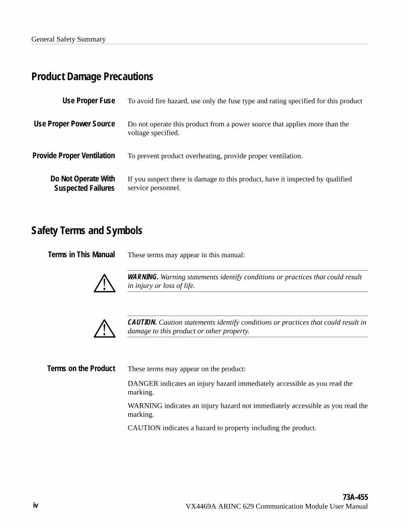
Product Damage Precautions
To avoid fire hazard, use only the fuse type and rating specified for this product
Do not operate this product from a power source that applies more than thevoltage specified.
To prevent product overheating, provide proper ventilation.
If you suspect there is damage to this product, have it inspected by qualifiedservice personnel.
Safety Terms and Symbols
These terms may appear in this manual:
WARNING. Warning statements identify conditions or practices that could resultin injury or loss of life.
CAUTION. Caution statements identify conditions or practices that could result indamage to this product or other property.
These terms may appear on the product:
DANGER indicates an injury hazard immediately accessible as you read themarking.
WARNING indicates an injury hazard not immediately accessible as you read themarking.
CAUTION indicates a hazard to property including the product.
Use Proper Fuse
Use Proper Power Source
Provide Proper Ventilation
Do Not Operate WithSuspected Failures
Terms in This Manual
Terms on the Product
General Safety Summary
73A-455VX4469A ARINC 629 Communication Module User Manual v
The following symbols may appear on the product:
DANGERHigh Voltage
Protective Ground(Earth) Terminal
ATTENTIONRefer toManual
Double Insulated
Symbols on the Product
73A-455VX4469A ARINC 629 Communication Module User Manual vii
Service Safety Summary
Only qualified personnel should perform service procedures. Read this ServiceSafety Summary and the General Safety Summary before performing any serviceprocedures.
Do not perform internal service or adjustments of this product unless anotherperson capable of rendering first aid and resuscitation is present.
To avoid electric shock, disconnect the main power by means of the power cordor, if provided, the power switch.
Dangerous voltages or currents may exist in this product. Disconnect power,remove battery (if applicable), and disconnect test leads before removingprotective panels, soldering, or replacing components.
To avoid electric shock, do not touch exposed connections.
Do Not Service Alone
Disconnect Power
Use Care When ServicingWith Power On


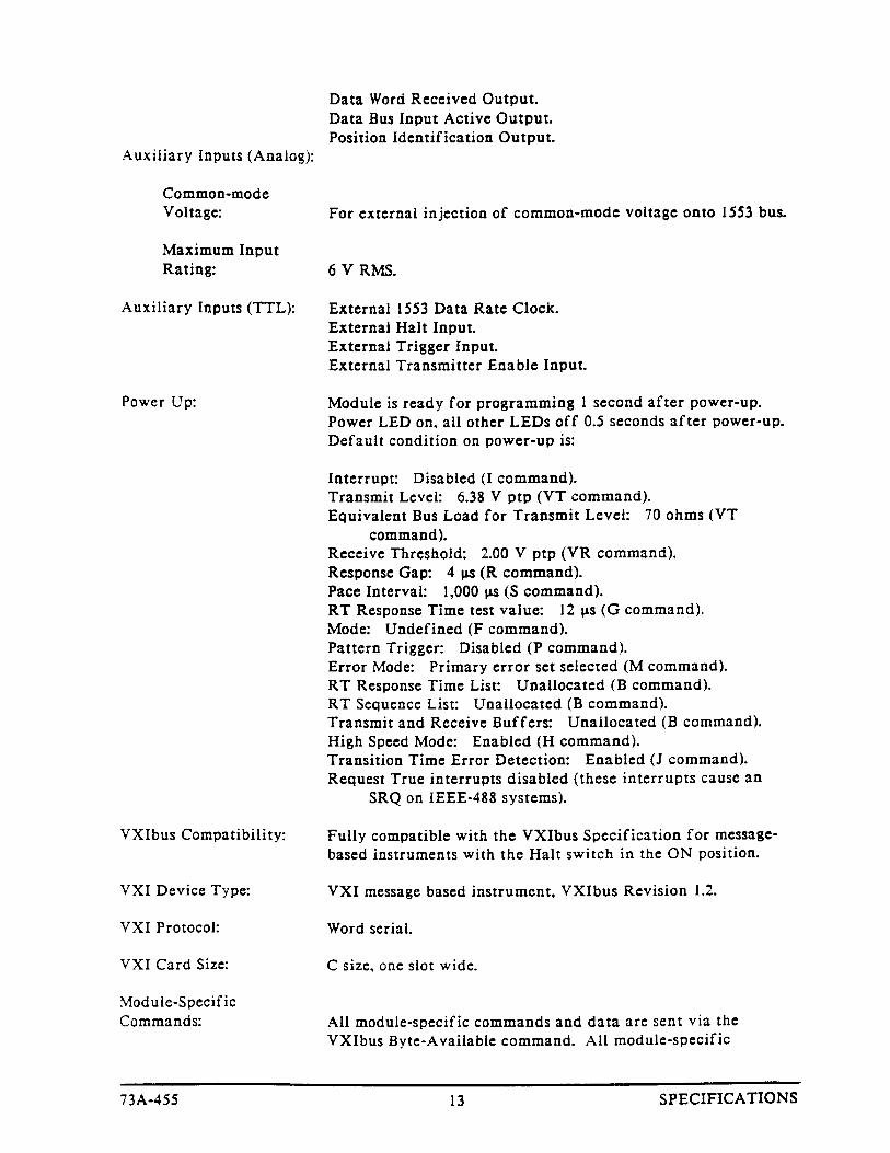
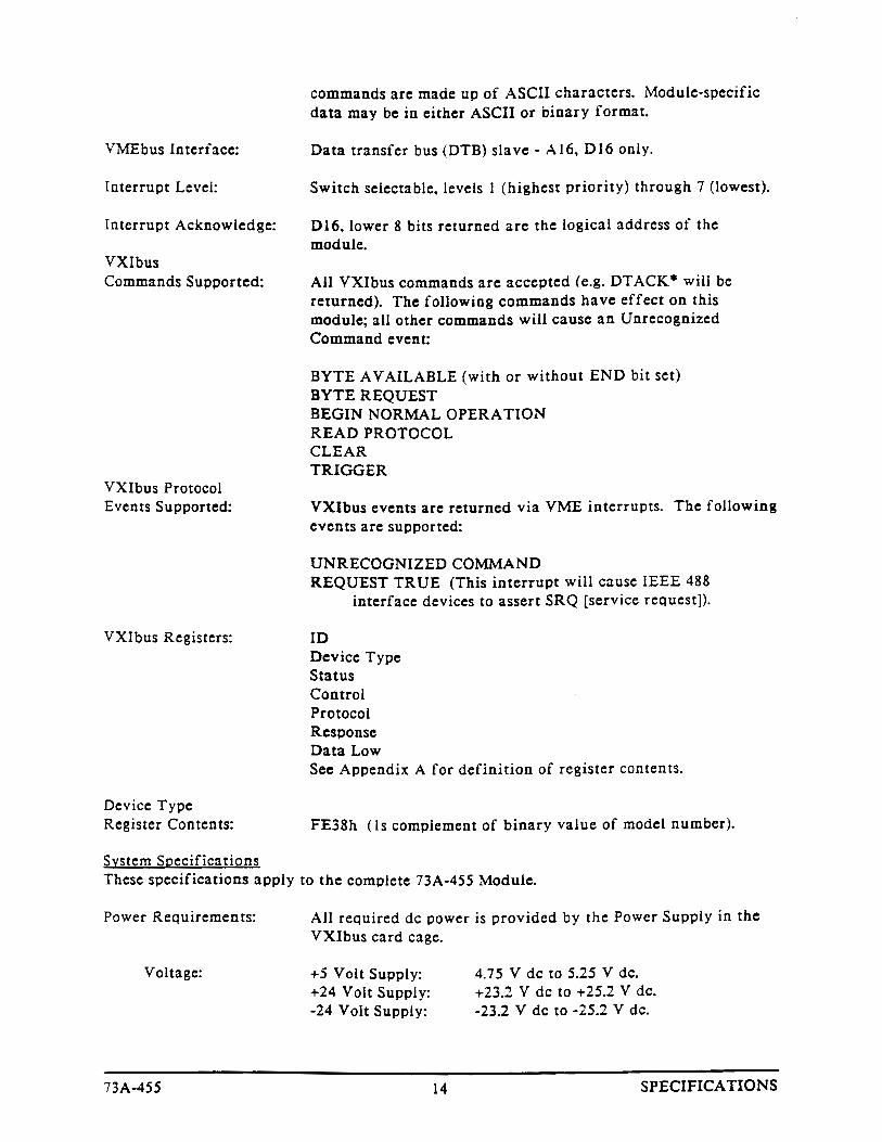
VXI Bus Radiated Emissions:
VXI Bus Conducted Emissions:


APPENDIX E - PERFORMANCE VERIFICATION
9973A-455 APPENDIX E
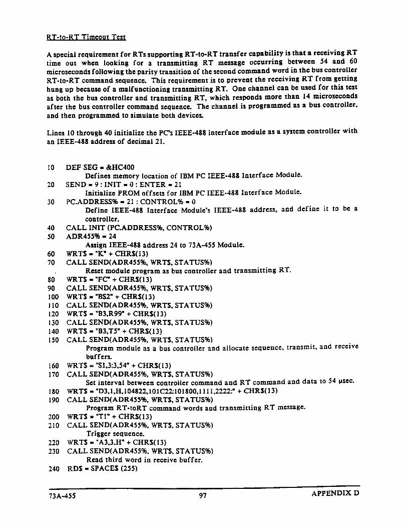
This procedure verifies the performance of the 73A-455 MIL-STD-1553 A/BBus Simulator Modules. Perform the verification in your current VXIbus systemif it meets the minimum requirements specified in the paragraph labeledRequired Equipment. It is not necessary to complete the entire procedure if youare only interested in a specific performance area. However, the verification ofsome parameters rely on the correct operation of previously validated functionsso it is best to follow the order presented.
Use the steps in this chapter to verify that the mainframe operates properly.
General Information and ConventionsThe following conventions apply throughout this procedure:
� Each of the voltage and bit tests direct you to figures that help you visualizewhat the signal should look like. You will be referred to a different figure ofa valid signal when the sample rate or voltage level changes.
� Programming of the 73A-455 assumes no particular interface. Refer toProgramming Examples in Basic for a list of the ASC commands that needto be sent to the 73A-455. Form the commands properly for the interface thatyou use.
� This procedure checks one of two channels of the 73A-455, then instructsyou to repeat the procedure for the other channel.
NOTE. Refer to the Command Syntax section of this manual for commandprotocol and syntax information.
PrerequisitesThe performance checks in this section are valid when the following require-ments are met:
� The 73A-455 passes the power-on self test.
� All covers are in place and the 73A-455 is installed in an approved VXIbusmainframe according to the instructions in the Installation section of theOperating Manual.
� The 73A-455 warms up at least 20 minutes in an ambient environment asspecified in the Specifications section of the Operating Manual.
100 73A-455APPENDIX E
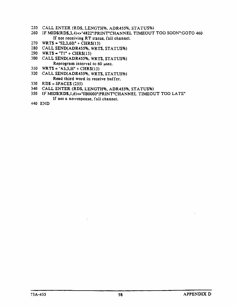
Required EquipmentThe following equipment is necessary to complete the performance verificationchecks:
� Digitizing oscilloscope with at least 500 MHz bandwidth, a samplefrequency of 1 GHz, and a minimum of 2 channels.
� A platform to send commands to the 73A-455 and receive data back from the73A-455.
� A cable to connect the direct coupled output of the 73A-455 from Direct Ato Direct B. This cable will need to have a TNC Triax connector on each endand a 35 ± 0.1% � load across the bus high to bus low connection tosimulate a 70 � 1553 bus load. Allow enough space to connect an oscillo-scope probe on both ends of the resistor. Mark which side of the resistor isBUS+ and BUS–. Refer to Figure 455-7.
� One DD50S connector to monitor signals from the 73A-455.
Bus highconnectionfor scope
Bus lowconnection for
scope
35 �Outer grip on
connector
Center pinon connector
Shield to connector case
Center pinon connector
Channel A
Channel B
Figure 455-7: Cable Diagram
10173A-455 APPENDIX E
Performance Verification CheckUse the checks in this section to verify the performance of the 73A-455.
Follow the steps below to verify that the clock and dividers are workingproperly:
1. Connect channel 1 of the oscilloscope to S4 pin 39 (position identificationoutput Bus A).
NOTE. Program the Bus A side of the 73A-455 module using the logical address.
2. Send the following commands to Bus A:
FC <cr/lf>
B0,T1 <cr/lf>
B0,R1 <cr/lf>
BS1 <cr/lf>
S1,0,50;<cr/lf>
D0,1,H,300821;<cr/lf>
VT820,35<cr/lf>
T*<cr/lf>
3. Verify that the Bus A CTRL, PATT, and COMM lights are illuminated.
4. Measure the time on channel 1, between the falling edge of one pulse to thefalling edge of the next pulse. A measurement of 70 �s ± 70 ns indicates thatthe clock and dividers are working properly. Refer to Figure 455-8.
5. Send the following command to the 73A-455 to make the transmitter quitand reset:
K<cr/lf>
6. Connect channel 1 of the oscilloscope to S4 pin 45 (position identificationoutput Bus B).
7. Send the following commands to Bus B:
FC <cr/lf>
B0,T1 <cr/lf>
B0,R1 <cr/lf>
Verify Clock Stability

102 73A-455APPENDIX E
BS1 <cr/lf>
S1,0,50;<cr/lf>
D0,1,H,300821;<cr/lf>
VT820,35<cr/lf>
T*<cr/lf>
8. Verify that the 73A-455 Bus B CTRL, PATT, and COMM lights are on.
9. Measure the time on channel 1 between the falling edge of one pulse to thefalling edge of the next pulse. Refer to Figure 455-8 to verify a measurementof 70 �s ± 70 ns. This measurement indicates that the clock and dividers areworking properly. .
10. Send the following command to the 73A-455 to make the transmitter quitand reset:
K<cr/lf>
Clock Accuracy70 �s ± 70ns
Figure 455-8: Clock Accuracy
10373A-455 APPENDIX E
Follow the steps below to verify that the 1553 bus output levels are accurate:
1. Connect one TNC Triax connector to the Direct A connector.
2. Connect a second TNC Triax connector to the Direct B connector.
3. Connect oscilloscope channel 1 to S4 pin 39. Connect channel 2 to BUS+ onthe resistor.
4. Place the probe ground connection on the BUS– side of the resistor.
5. Set the oscilloscope to trigger off channel 1.
Ignore the overshoot and ringing on the peaks of the pulses when measuring thepeak-to-peak amplitude of the 1553 message on channel 2. Refer to Figure 455-8to verify the peak-to-peak measurement.
Amplitude Test, Volts Peak-to-Peak. Follow the steps below to verify thepeak-to-peak voltage reading:
1. Send the following commands to Bus A:
FC <cr/lf>
B0,T1 <cr/lf>
B0,R1 <cr/lf>
BS1 <cr/lf>
S1,0,50;<cr/lf>
D0,1,H,300821;<cr/lf>
VT820,35<cr/lf>
T*<cr/lf>
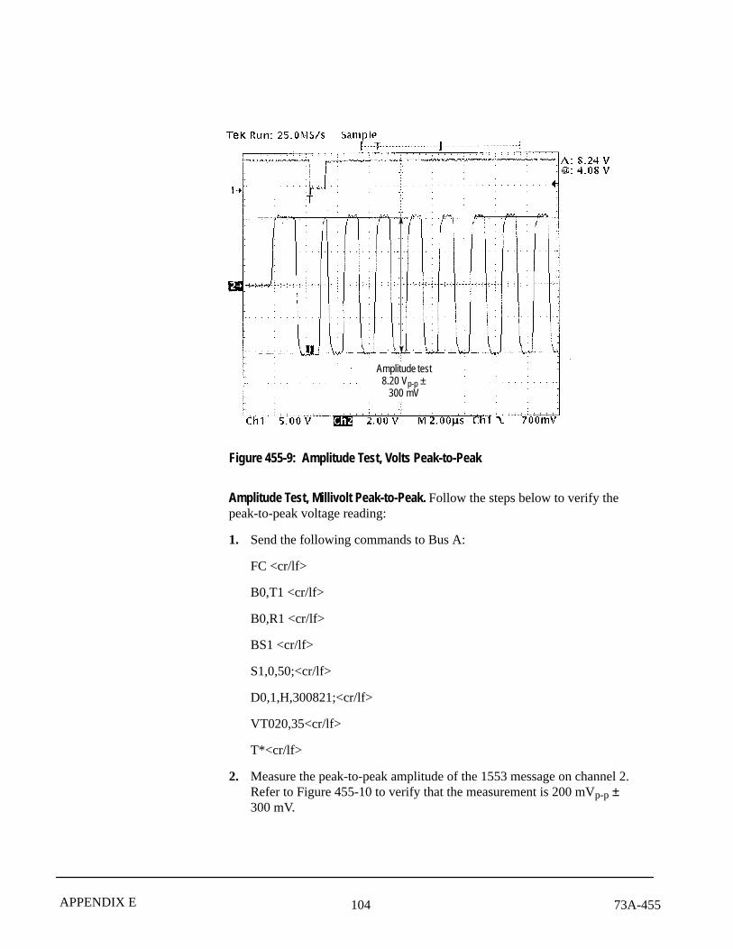
2. Measure the peak-to-peak amplitude. Verify that the reading is8.20 Vp-p ± 300 mV. Refer to Figure 455-9.
3. Send the following command to the 73A-455 to make the transmitter quitand reset:
K<cr/lf>
Verify 1553 Bus Output Levels
104 73A-455APPENDIX E
Amplitude test8.20 Vp-p ±
300 mV
Figure 455-9: Amplitude Test, Volts Peak-to-Peak
Amplitude Test, Millivolt Peak-to-Peak. Follow the steps below to verify thepeak-to-peak voltage reading:
1. Send the following commands to Bus A:
FC <cr/lf>
B0,T1 <cr/lf>
B0,R1 <cr/lf>
BS1 <cr/lf>
S1,0,50;<cr/lf>
D0,1,H,300821;<cr/lf>
VT020,35<cr/lf>
T*<cr/lf>
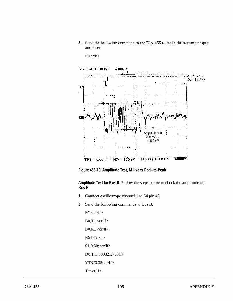
2. Measure the peak-to-peak amplitude of the 1553 message on channel 2.Refer to Figure 455-10 to verify that the measurement is 200 mVp-p ±300 mV.
10573A-455 APPENDIX E
3. Send the following command to the 73A-455 to make the transmitter quitand reset:
K<cr/lf>
Amplitude test200 mVp-p ± 300 mV
Figure 455-10: Amplitude Test, Millivolts Peak-to-Peak
Amplitude Test for Bus B. Follow the steps below to check the amplitude forBus B.
1. Connect oscilloscope channel 1 to S4 pin 45.
2. Send the following commands to Bus B:
FC <cr/lf>
B0,T1 <cr/lf>
B0,R1 <cr/lf>
BS1 <cr/lf>
S1,0,50;<cr/lf>
D0,1,H,300821;<cr/lf>
VT820,35<cr/lf>
T*<cr/lf>

106 73A-455APPENDIX E
3. Measure the peak-to-peak amplitude of the 1553 message on channel 2.Verify that the reading is 8.20 Vp-p ± 300 mV. Refer to Figure 455-9.
4. Send the following command to the 73A-455 to make the transmitter quitand reset:
K<cr/lf>
5. Send the following commands to Bus B:
FC <cr/lf>
B0,T1 <cr/lf>
B0,R1 <cr/lf>
BS1 <cr/lf>
S1,0,50;<cr/lf>
D0,1,H,300821;<cr/lf>
VT020,35<cr/lf>
T*<cr/lf>
6. Measure the peak-to-peak amplitude of the 1553 message on channel 2.Refer to Figure 455-10 to verify that the reading is 200 mV ± 300 mVp-p.
7. Send the following command to the 73A-455 to make the transmitter quitand reset:
K<cr/lf>
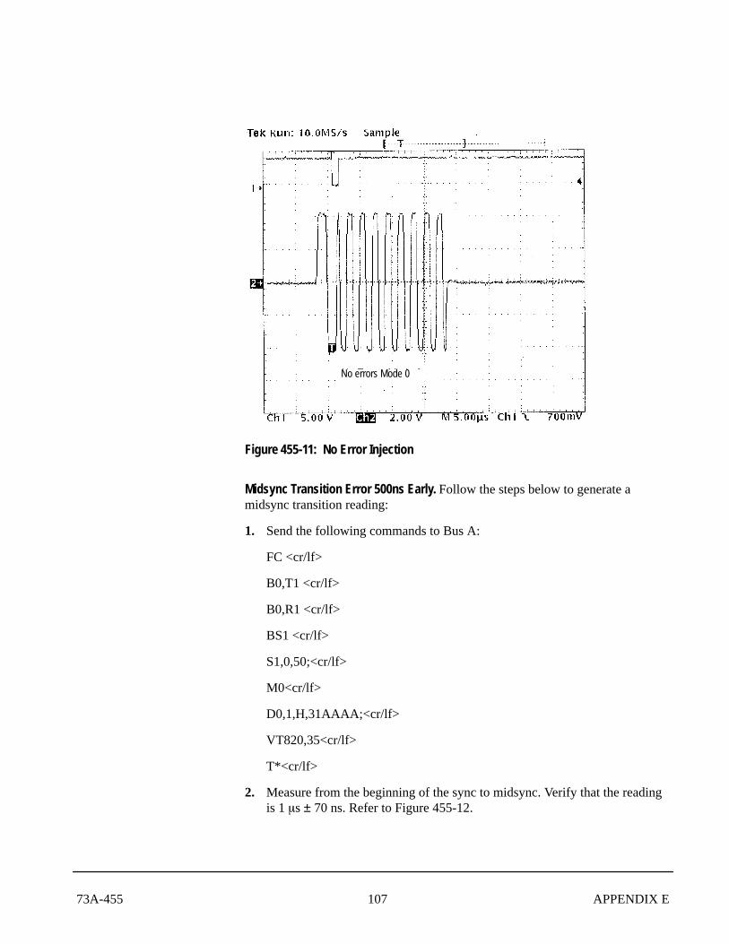
Follow the steps below to verify that there is no error in the injection transmis-sion. Refer to Figure 455-11.
1. Connect one TNC Triax connector to the Direct A connector.
2. Connect a second TNC Triax connector to the Direct B connector.
3. Connect oscilloscope channel 1 to S4 pin 39 and channel 2 to BUS+ on theresistor.
4. Place the probe ground connection on the BUS– side of the resistor.
5. Set the oscilloscope to trigger off channel 1.
Error Injection Test
10773A-455 APPENDIX E
No errors Mode 0
Figure 455-11: No Error Injection
Midsync Transition Error 500ns Early. Follow the steps below to generate amidsync transition reading:
1. Send the following commands to Bus A:
FC <cr/lf>
B0,T1 <cr/lf>
B0,R1 <cr/lf>
BS1 <cr/lf>
S1,0,50;<cr/lf>
M0<cr/lf>
D0,1,H,31AAAA;<cr/lf>
VT820,35<cr/lf>
T*<cr/lf>
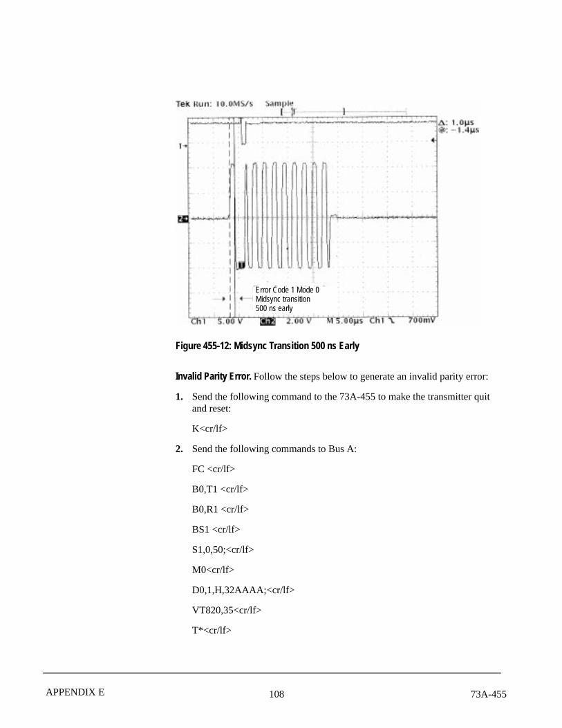
2. Measure from the beginning of the sync to midsync. Verify that the readingis 1 �s ± 70 ns. Refer to Figure 455-12.
108 73A-455APPENDIX E
Error Code 1 Mode 0Midsync transition500 ns early
Figure 455-12: Midsync Transition 500 ns Early
Invalid Parity Error. Follow the steps below to generate an invalid parity error:
1. Send the following command to the 73A-455 to make the transmitter quitand reset:
K<cr/lf>
2. Send the following commands to Bus A:
FC <cr/lf>
B0,T1 <cr/lf>
B0,R1 <cr/lf>
BS1 <cr/lf>
S1,0,50;<cr/lf>
M0<cr/lf>
D0,1,H,32AAAA;<cr/lf>
VT820,35<cr/lf>
T*<cr/lf>
10973A-455 APPENDIX E
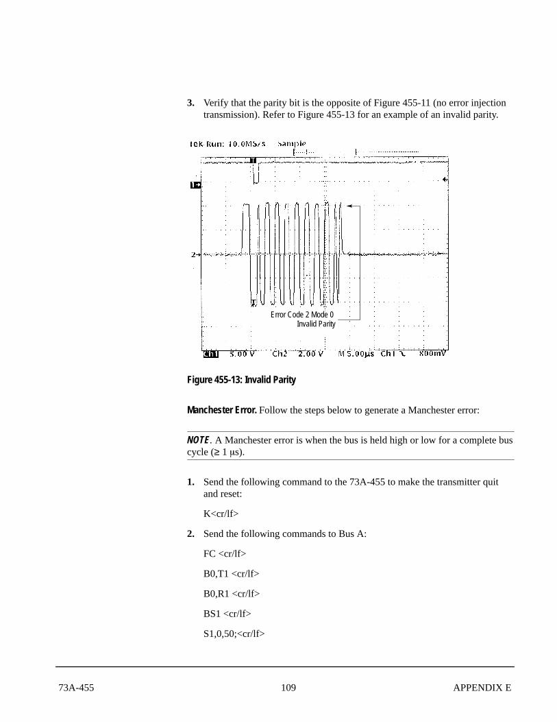
3. Verify that the parity bit is the opposite of Figure 455-11 (no error injectiontransmission). Refer to Figure 455-13 for an example of an invalid parity.
Error Code 2 Mode 0 Invalid Parity
Figure 455-13: Invalid Parity
Manchester Error. Follow the steps below to generate a Manchester error:
NOTE. A Manchester error is when the bus is held high or low for a complete buscycle (≥ 1 �s).
1. Send the following command to the 73A-455 to make the transmitter quitand reset:
K<cr/lf>
2. Send the following commands to Bus A:
FC <cr/lf>
B0,T1 <cr/lf>
B0,R1 <cr/lf>
BS1 <cr/lf>
S1,0,50;<cr/lf>
110 73A-455APPENDIX E
M0<cr/lf>
D0,1,H,33AAAA;<cr/lf>
VT820,35<cr/lf>
T*<cr/lf>
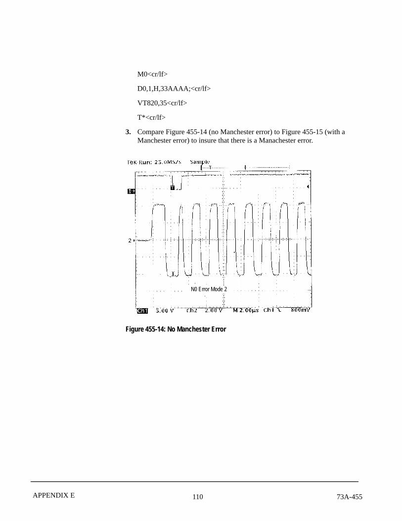
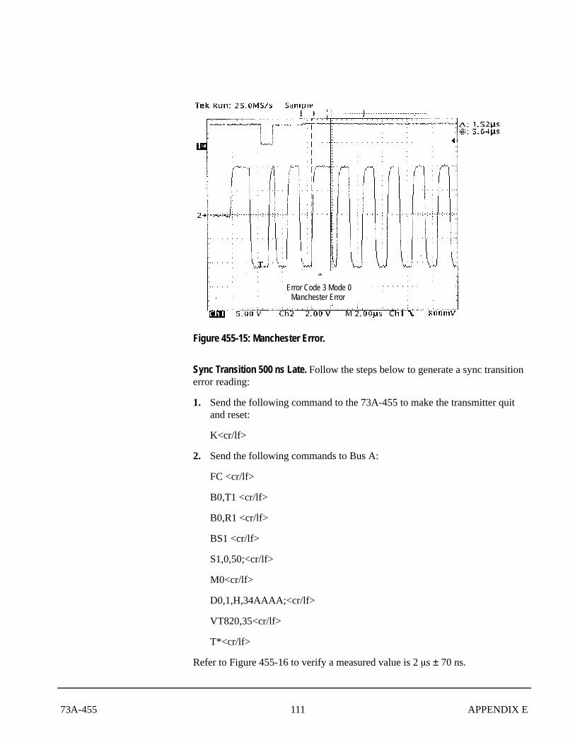
3. Compare Figure 455-14 (no Manchester error) to Figure 455-15 (with aManchester error) to insure that there is a Manachester error.
N0 Error Mode 2
Figure 455-14: No Manchester Error
11173A-455 APPENDIX E
Error Code 3 Mode 0Manchester Error
Figure 455-15: Manchester Error.
Sync Transition 500 ns Late. Follow the steps below to generate a sync transitionerror reading:
1. Send the following command to the 73A-455 to make the transmitter quitand reset:
K<cr/lf>
2. Send the following commands to Bus A:
FC <cr/lf>
B0,T1 <cr/lf>
B0,R1 <cr/lf>
BS1 <cr/lf>
S1,0,50;<cr/lf>
M0<cr/lf>
D0,1,H,34AAAA;<cr/lf>
VT820,35<cr/lf>
T*<cr/lf>
Refer to Figure 455-16 to verify a measured value is 2 �s ± 70 ns.
112 73A-455APPENDIX E
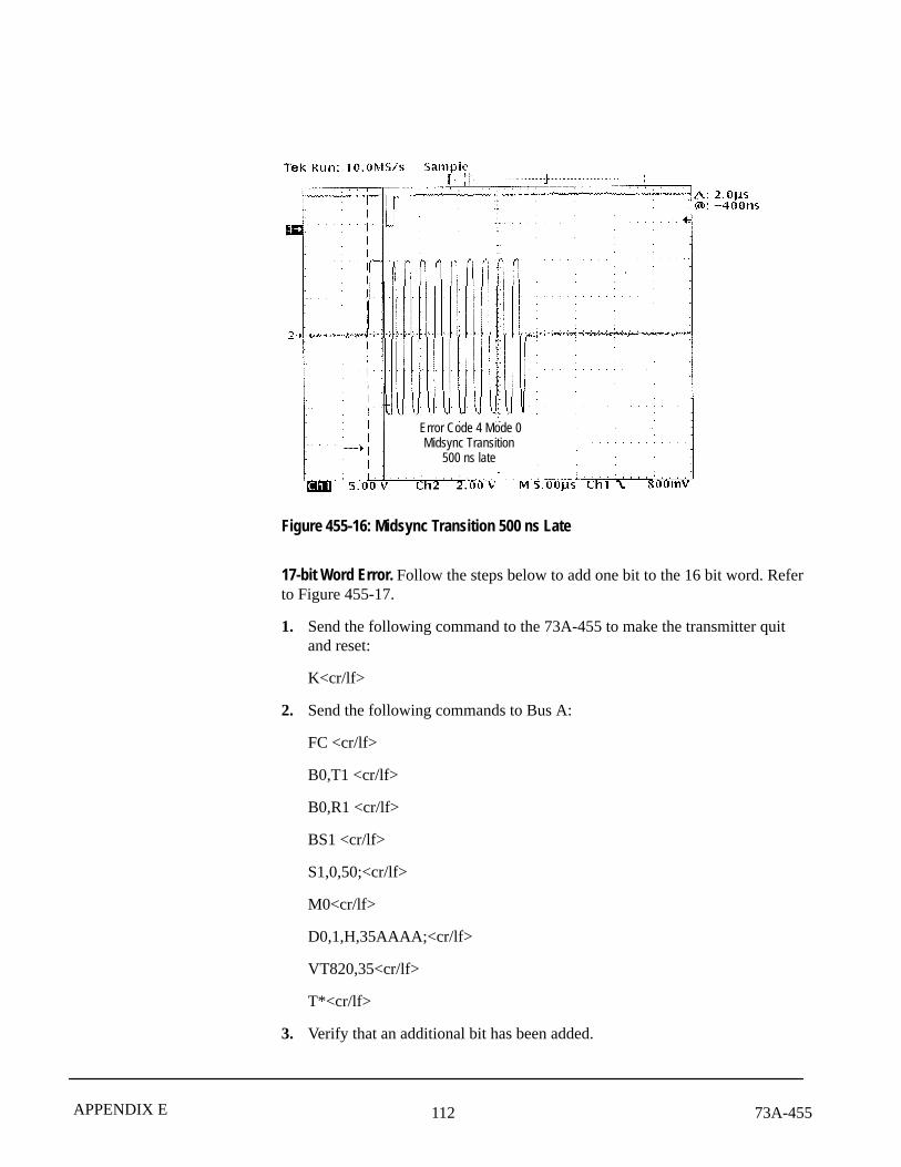
Error Code 4 Mode 0Midsync Transition
500 ns late
Figure 455-16: Midsync Transition 500 ns Late
17-bit Word Error. Follow the steps below to add one bit to the 16 bit word. Referto Figure 455-17.
1. Send the following command to the 73A-455 to make the transmitter quitand reset:
K<cr/lf>
2. Send the following commands to Bus A:
FC <cr/lf>
B0,T1 <cr/lf>
B0,R1 <cr/lf>
BS1 <cr/lf>
S1,0,50;<cr/lf>
M0<cr/lf>
D0,1,H,35AAAA;<cr/lf>
VT820,35<cr/lf>
T*<cr/lf>
3. Verify that an additional bit has been added.
11373A-455 APPENDIX E
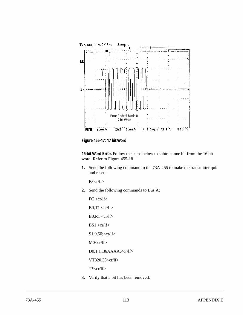
Error Code 5 Mode 017 bit Word
Figure 455-17: 17 bit Word
15-bit Word Error. Follow the steps below to subtract one bit from the 16 bitword. Refer to Figure 455-18.
1. Send the following command to the 73A-455 to make the transmitter quitand reset:
K<cr/lf>
2. Send the following commands to Bus A:
FC <cr/lf>
B0,T1 <cr/lf>
B0,R1 <cr/lf>
BS1 <cr/lf>
S1,0,50;<cr/lf>
M0<cr/lf>
D0,1,H,36AAAA;<cr/lf>
VT820,35<cr/lf>
T*<cr/lf>
3. Verify that a bit has been removed.
114 73A-455APPENDIX E
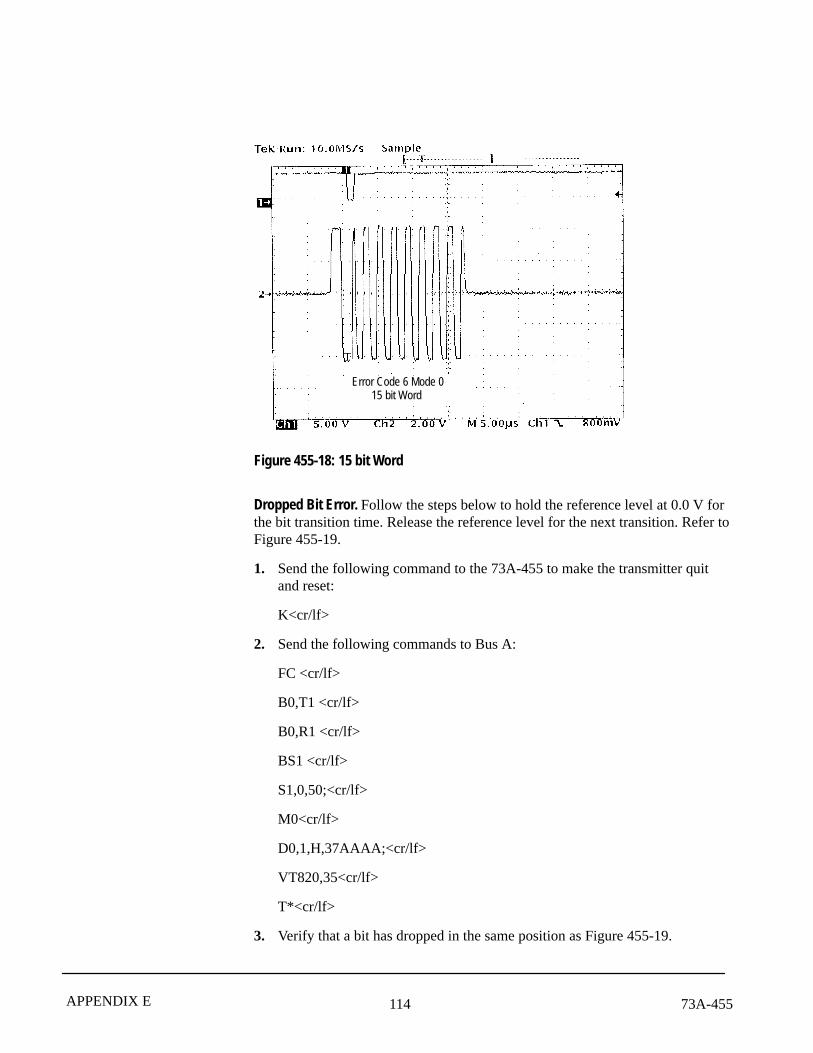
Error Code 6 Mode 015 bit Word
Figure 455-18: 15 bit Word
Dropped Bit Error. Follow the steps below to hold the reference level at 0.0 V forthe bit transition time. Release the reference level for the next transition. Refer toFigure 455-19.
1. Send the following command to the 73A-455 to make the transmitter quitand reset:
K<cr/lf>
2. Send the following commands to Bus A:
FC <cr/lf>
B0,T1 <cr/lf>
B0,R1 <cr/lf>
BS1 <cr/lf>
S1,0,50;<cr/lf>
M0<cr/lf>
D0,1,H,37AAAA;<cr/lf>
VT820,35<cr/lf>
T*<cr/lf>
3. Verify that a bit has dropped in the same position as Figure 455-19.

11573A-455 APPENDIX E
Error Code 7 Mode 0Dropped bit
Figure 455-19: Dropped Bit
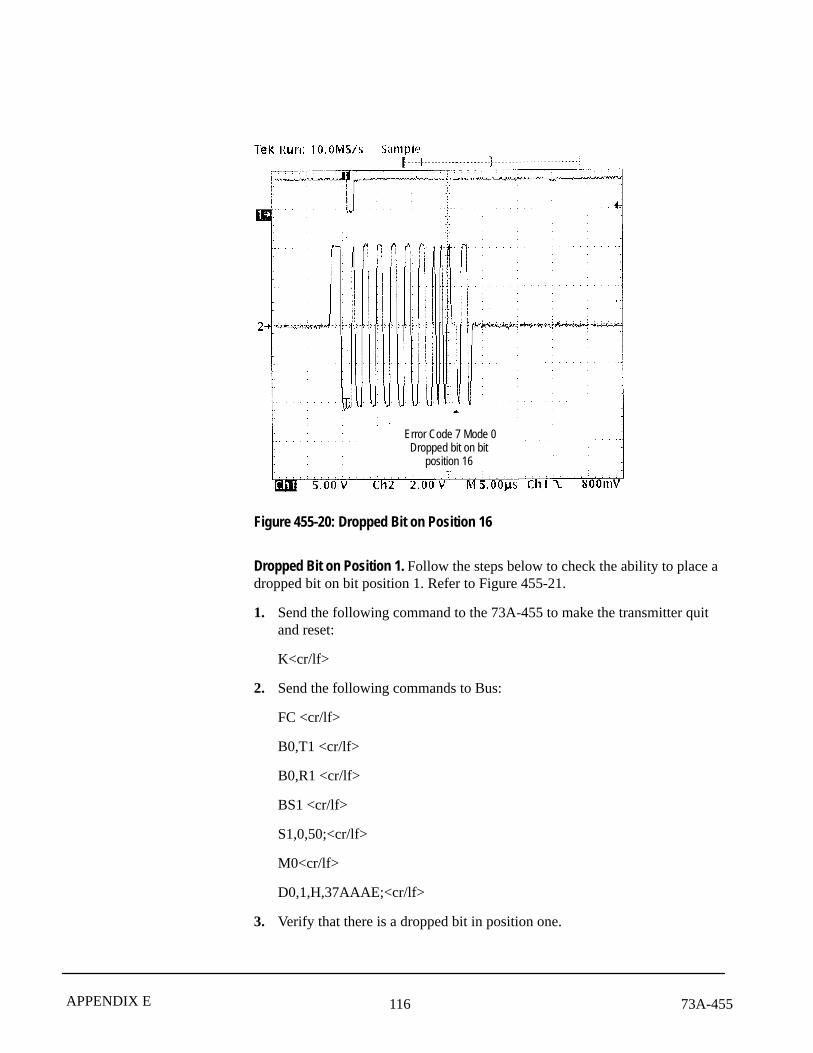
Dropped Bit on Position 16. Follow the steps below to check the ability of the73A-455 to place a dropped bit on bit position 16. Refer to Figure 455-20.
1. Send the following command to the 73A-455 to make the transmitter quitand reset:
K<cr/lf>
2. Send the following commands to Bus A:
FC <cr/lf>
B0,T1 <cr/lf>
B0,R1 <cr/lf>
BS1 <cr/lf>
S1,0,50;<cr/lf>
M0<cr/lf>
D0,1,H,37AAA0;<cr/lf>
VT820,35<cr/lf>
T*<cr/lf>
3. Verify that there is a dropped bit in position 16.
116 73A-455APPENDIX E
Error Code 7 Mode 0Dropped bit on bit
position 16
Figure 455-20: Dropped Bit on Position 16
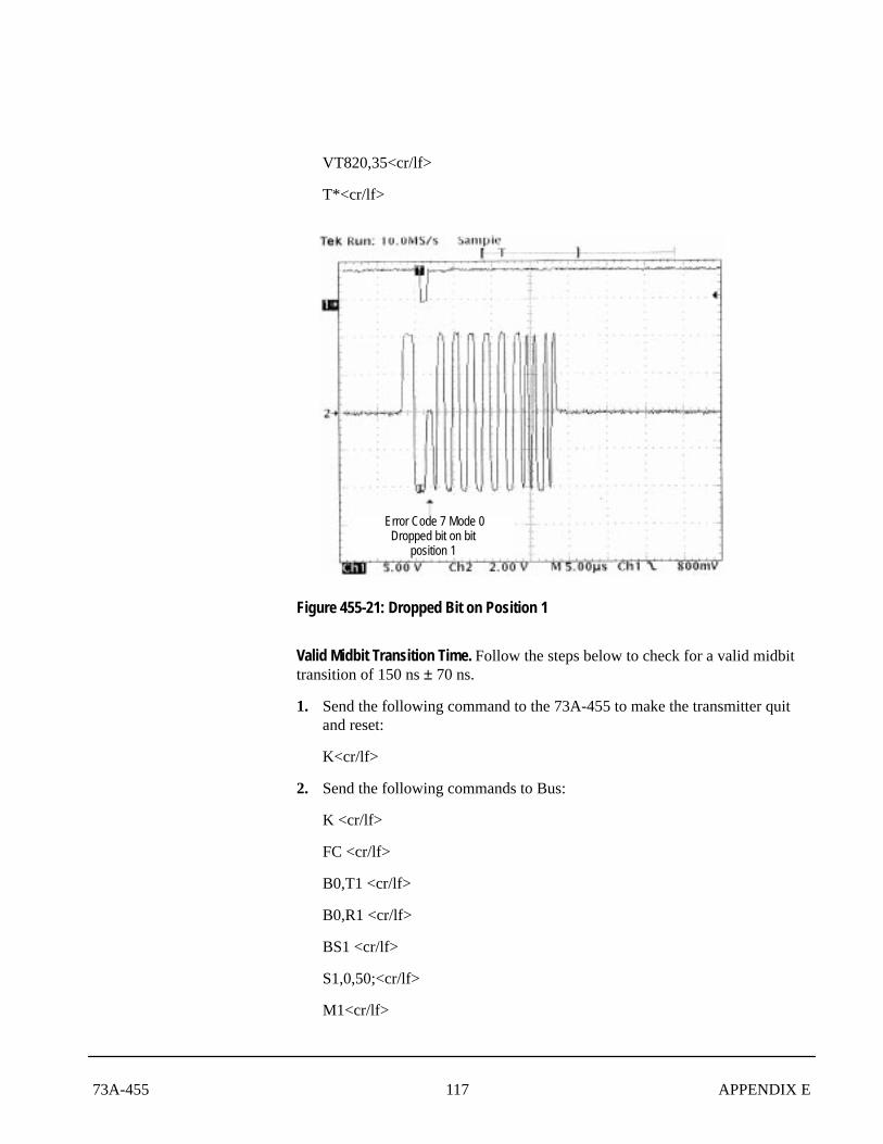
Dropped Bit on Position 1. Follow the steps below to check the ability to place adropped bit on bit position 1. Refer to Figure 455-21.
1. Send the following command to the 73A-455 to make the transmitter quitand reset:
K<cr/lf>
2. Send the following commands to Bus:
FC <cr/lf>
B0,T1 <cr/lf>
B0,R1 <cr/lf>
BS1 <cr/lf>
S1,0,50;<cr/lf>
M0<cr/lf>
D0,1,H,37AAAE;<cr/lf>
3. Verify that there is a dropped bit in position one.
11773A-455 APPENDIX E
VT820,35<cr/lf>
T*<cr/lf>
Error Code 7 Mode 0Dropped bit on bit
position 1
Figure 455-21: Dropped Bit on Position 1
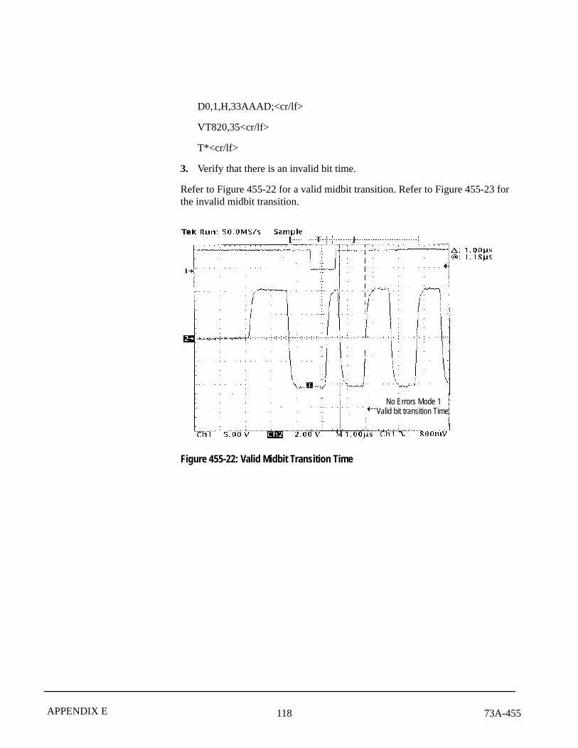
Valid Midbit Transition Time. Follow the steps below to check for a valid midbittransition of 150 ns ± 70 ns.
1. Send the following command to the 73A-455 to make the transmitter quitand reset:
K<cr/lf>
2. Send the following commands to Bus:
K <cr/lf>
FC <cr/lf>
B0,T1 <cr/lf>
B0,R1 <cr/lf>
BS1 <cr/lf>
S1,0,50;<cr/lf>
M1<cr/lf>
118 73A-455APPENDIX E
D0,1,H,33AAAD;<cr/lf>
VT820,35<cr/lf>
T*<cr/lf>
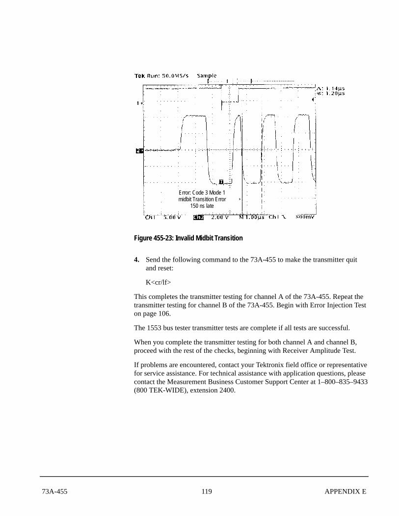
3. Verify that there is an invalid bit time.
Refer to Figure 455-22 for a valid midbit transition. Refer to Figure 455-23 forthe invalid midbit transition.
No Errors Mode 1Valid bit transition Time
Figure 455-22: Valid Midbit Transition Time
11973A-455 APPENDIX E
Error: Code 3 Mode 1midbit Transition Error
150 ns late
Figure 455-23: Invalid Midbit Transition
4. Send the following command to the 73A-455 to make the transmitter quitand reset:
K<cr/lf>
This completes the transmitter testing for channel A of the 73A-455. Repeat thetransmitter testing for channel B of the 73A-455. Begin with Error Injection Teston page 106.
The 1553 bus tester transmitter tests are complete if all tests are successful.
When you complete the transmitter testing for both channel A and channel B,proceed with the rest of the checks, beginning with Receiver Amplitude Test.
If problems are encountered, contact your Tektronix field office or representativefor service assistance. For technical assistance with application questions, pleasecontact the Measurement Business Customer Support Center at 1–800–835–9433(800 TEK-WIDE), extension 2400.
120 73A-455APPENDIX E
Follow the steps below to verify the receiver amplitude:
1. Remove the channel 1 and channel 2 oscilloscope probes from the busresistor.
2. Connect the bus cable between Direct A and Direct B connectors of the73A-455.
3. Send the following commands to channel B Remote Terminal (RT):
K<cr/lf>
FR<cr/lf>
B20,T3<cr/lf>
B20,R3<cr/lf>
D20,1,H,10A000,001111,00EEEE;<cr/lf>
VT820,35<cr/lf>
VR785<cr/lf>
T1<cr/lf>
4. Send the following commands to channel A Bus Controller (BC):
K<cr/lf>
FC<cr/lf>
B1,T1<cr/lf>
B1,R5<cr/lf>
BS1<cr/lf>
S1,1,1000;<cr/lf>
D1,1,H,10A422;<cr/lf>
VT820,35<cr/lf>
VR785<cr/lf>
T1<cr/lf>
5. Wait approximately 100 �s before sending out any other commands.
6. Send the following commands to the BC:
Q<cr/lf>
A1,1,H<cr/lf>
Receiver Amplitude Test
12173A-455 APPENDIX E
7. Read back the following five words from the BC:
10A422
10A000
001111
00EEEE
0B0000
The first two bytes of each word may differ, but the last four bytes mustmatch each of the above listed words.
8. Send the following commands to the RT:
Q<cr/LF>
A20,1,H<cr/lf>
9. Read back the following two words from the RT:
10A422
0B0000
The first two bytes of each word may differ, but the last four bytes mustmatch each of the above listed words.
10. Send the following commands to channel B:
VR820<cr/lf>
T1<cr/lf>
11. Send the following commands to channel A:
VR820<cr/lf>
T1<cr/lf>
12. Wait approximately 100 �s before sending out any other commands.
13. Send the following commands to the BC:
Q<cr/lf>
A1,1,H<cr/lf>
14. Read back the following word from the BC:
0B0000
The last four bytes should match the above word.
122 73A-455APPENDIX E
15. Send the following commands to the RT:
Q<cr/LF>
A20,1,H<cr/lf>
16. Read back the following word from the RT:
0B0000
The last four bytes should match the above word.
17. Send the following commands to channel B:
VT100,35<cr/lf>
VR50<cr/lf>
T1<cr/lf>
18. Send the following commands to channel A:
VT100,35<cr/lf>
VR50<cr/lf>
T1<cr/lf>
19. Wait approximately 100 �s before sending out any other commands.
20. Send the following commands to the BC:
Q<cr/lf>
A1,1,H<cr/lf>
21. Read back the following five words from the BC:
10A422
10A000
001111
00EEEE
0B0000
The first two bytes of each word may differ, but the last four bytes mustmatch each of the above listed words.
12373A-455 APPENDIX E
22. Send the following commands to the RT:
Q<cr/LF>
A20,1,H<cr/lf>
23. Read back the following two words from the RT:
10A422
0B0000
The first two bytes of each word may differ, but the last four bytes mustmatch each of the above listed words.
24. Send the following commands to channel B:
VT040,35<cr/lf>
T1<cr/lf>
25. Send the following commands to channel A:
VT040,35<cr/lf>
T1<cr/lf>
26. Wait approximately 100 �s before sending out any other commands.
27. Send the following commands to the BC:
Q<cr/lf>
A1,1,H<cr/lf>
28. Read back the following word from the BC:
0B0000
The first two bytes of each word may differ, but the last four bytes mustmatch each of the above listed words.
29. Send the following commands to the RT:
Q<cr/LF>
A20,1,H<cr/lf>
124 73A-455APPENDIX E
30. Read back the following word from the RT:
0B0000
The first two bytes of each word may differ, but the last four bytes mustmatch each of the above listed words.
This completes the Receiver Amplitude Test.
12573A-455 APPENDIX E
Follow the steps below to complete the Receiver Error Detection test:
1. Send the following commands to channel B:
K<cr/lf>
FR<cr/lf>
B20,T3<cr/lf>
B20,R3<cr/lf>
D20,1,H,10A000,001111,01EEEE;<cr/lf>
VT620,35<cr/lf>
VR200<cr/lf>
T1<cr/lf>
2. Send the following commands to channel A:
K<cr/lf>
FC<cr/lf>
B1,T1<cr/lf>
B1,R5<cr/lf>
BS1<cr/lf>
S1,1,1000;<cr/lf>
D1,1,H,10A422;<cr/lf>
VT620,35<cr/lf>
VR200<cr/lf>
T1<cr/lf>
3. Wait approximately 100 �s before sending out any other commands.
4. Send the following commands to the BC:
Q<cr/lf>
A1,1,H<cr/lf>
Receiver Error Detection Test
126 73A-455APPENDIX E
5. Read back the following five words from the BC:
10A422
10A000
001111
04EEEE
0B0000
Each word must match the above listed word.
6. Send the following commands to the RT:
Q<cr/LF>
A20,1,H<cr/lf>
7. Read back the following two words from the RT:
10A422
0B0000
Each word must match the above listed word.
8. Send the following commands to channel B:
D20,3,H,02EEEE;<cr/lf>
T1<cr/lf>
9. Send the following commands to channel A:
T1<cr/lf>
10. Wait approximately 100 �s before sending out any other commands.
11. Send the following commands to the BC:
Q<cr/lf>
A1,1,H<cr/lf>
12773A-455 APPENDIX E
12. Read back the following five words from the BC:
10A422
10A000
001111
02EEEE
0B0000
Each word must match the above listed word.
13. Send the following commands to the RT:
Q<cr/LF>
A20,1,H<cr/lf>
14. Read back the following two words from the RT:
10A422
0B0000
Each word must match the above listed word.
15. Send the following commands to channel B:
D20,3,H,03EEEE;<cr/lf>
T1<cr/lf>
16. Send the following commands to channel A:
T1<cr/lf>
17. Wait approximately 100 �s before sending out any other commands.
18. Send the following commands to the BC:
Q<cr/lf>
A1,1,H<cr/lf>
128 73A-455APPENDIX E
19. Read back the following five words from the BC:
10A422
10A000
001111
03EEEE
0B0000
Each word must match the above listed word.
20. Send the following commands to the RT:
Q<cr/LF>
A20,1,H<cr/lf>
21. Read back the following two words from the RT:
10A422
0B0000
Each word must match the above listed word.
22. Send the following commands to channel B:
D20,3,H,04EEEE;<cr/lf>
T1<cr/lf>
23. Send the following commands to channel A:
T1<cr/lf>
24. Wait approximately 100 �s before sending out any other commands.
25. Send the following commands to the BC:
Q<cr/lf>
A1,1,H<cr/lf>
12973A-455 APPENDIX E
26. Read back the following five words from the BC:
10A422
10A000
001111
04EEEE
0B0000
Each word must match the above listed word.
27. Send the following commands to the RT:
Q<cr/LF>
A20,1,H<cr/lf>
28. Read back the following two words from the RT:
10A422
0B0000
Each word must match the above listed word.
29. Send the following commands to channel B:
D20,2,H,051111,00EEEE;<cr/lf>
T1<cr/lf>
30. Send the following commands to channel A:
T1<cr/lf>
31. Wait approximately 100 �s before sending out any other commands.
32. Send the following commands to the BC:
Q<cr/lf>
A1,1,H<cr/lf>

130 73A-455APPENDIX E
33. Read back the following five words from the BC:
10A422
10A000
001111
05EEEE
0B0000
Each word must match the above listed word.
34. Send the following commands to the RT:
Q<cr/LF>
A20,1,H<cr/lf>
35. Read back the following two words from the RT:
10A422
0B0000
Each word must match the above listed word.
36. Send the following commands to channel B:
D20,2,H,001111,06EEEE;<cr/lf>
T1<cr/lf>
37. Send the following commands to channel A:
T1<cr/lf>
38. Wait approximately 100 �s before sending out any other commands.
39. Send the following commands to the BC:
Q<cr/lf>
A1,1,H<cr/lf>
13173A-455 APPENDIX E
40. Read back the following five words from the BC. This requires fivereadbacks of eight bytes each.
10A422
10A000
001111
06EEEE
0B0000
Each word must match the above listed word.
41. Send the following commands to the RT:
Q<cr/LF>
A20,1,H<cr/lf>
42. Read back the following two words from the RT:
10A422
0B0000
Each word must match the above listed word.
43. Send the following commands to channel B:
D20,3,H,072222;<cr/lf>
T1<cr/lf>
44. Send the following commands to channel A:
T1<cr/lf>
45. Wait approximately 100 �s before sending out any other commands.
46. Send the following commands to the BC:
Q<cr/lf>
A1,1,H<cr/lf>
132 73A-455APPENDIX E
47. Read back the following five words from the BC:
10A422
10A000
001111
072222
0B0000
Each word must match the above listed word.
48. Send the following commands to the RT:
Q<cr/LF>
A20,1,H<cr/lf>
49. Read back the following 2words from the RT:
10A422
0B0000
Each word must match the above listed word.
50. Send the following commands to channel B:
BR1<cr/lf>
R1,5<cr/lf>
D20,3,H,00EEEE;<cr/lf>
T1<cr/lf>
51. Send the following commands to channel A:
G4<cr/lf>
T1<cr/lf>
52. Wait approximately 100 �s before sending out any other commands.
53. Send the following commands to the BC:
Q<cr/lf>
A1,1,H<cr/lf>
13373A-455 APPENDIX E
54. Read back the following five words from the BC:
10A422
11A000
011111
01EEEE
0B0000
Each word must match the above listed word.
55. Send the following commands to the RT:
Q<cr/LF>
A20,1,H<cr/lf>
56. Read back the following two words from the RT:
10A422
0B0000
Each word must match the above listed word.
57. Send the following commands to channel B:
BR1<cr/lf>
R1,4<cr/lf>
D20,3,H,00EEEE;<cr/lf>
T1<cr/lf>
58. Send the following commands to channel A:
G5<cr/lf>
D1,1,H,10A420;<cr/lf>
T1<cr/lf>
59. Wait approximately 100 �s before sending out any other commands.
60. Send the following commands to the BC:
Q<cr/lf>
A1,1,HF<cr/lf>
134 73A-455APPENDIX E
61. Read back the following five words from the BC:
19A420
10A000
001111
00EEEE or 0CEEEE
0B0000
Each word must match the above listed word.
62. Send the following commands to the RT:
Q<cr/LF>
A20,1,HF<cr/lf>
63. Read back the following two words from the RT:
10A422
0B0000
Each word must match the above listed word.
64. Repeat the Receiver Error Detection Test on page 120, reversing the functionof the 73A-455 by making channel A the RT and channel B the BC.
The receiver tests are complete if all tests are successful.
13573A-455 APPENDIX E
Follow the steps below to verify the performance of the memory and CPU:
1. Send the following command to channel A:
TEST<cr/lf>
2. Wait until all of the lights on channel A of the 73A-455 module have quitblinking.
3. Verify the 73A-455 displays the following message:
OK, Vx.x
NOTE. Vx.x indicates the version and revision level of the firmware.
If the above message is received, then there are no errors in the memory or CPU.
4. Repeat the memory and CPU test for the channel B.
If all performance checks in this section are verified, then the 73A-455 isoperational.
If problems are encountered, contact your Tektronix field office or representativefor service assistance. For technical assistance with application questions, pleasecontact the Measurement Business Customer Support Center at 1-800-835-9433(800 TEK-WIDE), extension 2400.
Memory and CPU Test
�
��� ������ �
�����������
�
��������� �
�
��� ������ �