Embed Size (px)
Citation preview

XLS1000 Smoke Management Application Manual
P/N 74-3118 • Rev 2.0 • 04APR03

DEVELOPED BY Edwards Systems Technology 6411 Parkland Drive Sarasota, FL 34243 (941) 739-4300
COPYRIGHT NOTICE Copyright © 2003. All rights reserved.
This manual and the products it describes are copyrighted by Honeywell. You may not reproduce, translate, transcribe, or transmit any part of this manual without express, written permission from Honeywell.
This manual contains proprietary information intended for distribution to authorized persons or companies for the sole purpose of conducting business with Honeywell. If you distribute any information contained in this manual to unauthorized persons, you have violated all distributor agreements and we may take legal action.
TRADEMARKS IBM is a trademark of International Business Machines Corporation.
Microsoft is a trademark of Microsoft Corporation.
Microsoft Mouse is a trademark of Microsoft Corporation.
OS/2 is a registered trademark of International Business Machines Corporation.
Paradise is a trademark of Western Digital Corp.
Windows and Windows 95 are trademarks of Microsoft Corporation.
CREDITS This manual was designed and written by the EST Technical Services - Documentation Department, Sarasota.
DOCUMENT HISTORY
Date Revision Reason for change
DDMONYY 1.0 Initial release
04APR03 2.0 Subsequent release
Changed: FSCS to FSCS series.

XLS1000 Smoke Management Application Manual i
Content
Chapter 1 Building fire geometry and smoke movement • 1.1 Introduction to the fire problem • 1.2 Products of combustion • 1.4 Principals of smoke-control • 1.14 Types of systems • 1.18 Smoke-control system components • 1.36 Additional reading • 1.51
Chapter 2 XLS1000 smoke-control system hardware • 2.1 The XLS1000 smoke-control system • 2.2 XLS1000 smoke-control system design considerations • 2.5 FSCS firefighter's smoke-control station (FSCS) • 2.14 Components • 2.32 FSCS series smoke control graphics annunciators • 2.41 FSCS current requirements • 2.47 Wiring diagrams • 2.48
Chapter 3 Smoke-control system programming • 3.1 Programming smoke-control • 3.2 Understanding objects, labels, and rules • 3.4 Developing a labeling plan • 3.6 Smoke-control considerations and sequencing • 3.8 Rules for smoke-control programming • 3.11 Rule example • 3.15 HVAC and system control examples • 3.18
Chapter 4 Smoke-control acceptance and testing • 4.1 Testing • 4.2 Smoke-control panel acceptance test procedure • 4.3 XLS1000 SCS detection acceptance testing • 4.13 Smoke-control input modules • 4.15 Smoke-control output modules • 4.16 Dedicated systems • 4.17 Additional considerations • 4.21
Glossary • Y.1
Content
ii XLS1000 Smoke Management Application Manual
Important information
Limitation of liability This product has been designed to meet the requirements of NFPA Standard 72, 1999 Edition; Underwriters Laboratories, Inc., Standard 864, 8th Edition; and Underwriters Laboratories of Canada, Inc., Standard ULC S527. Installation in accordance with this manual, applicable codes, and the instructions of the authority having jurisdiction (AHJ) is mandatory. EST shall not under any circumstances be liable for any incidental or consequential damages arising from loss of property or other damages or losses owing to the failure of EST products beyond the cost of repair or replacement of any defective products. EST reserves the right to make product improvements and change product specifications at any time.
While every precaution has been taken during the preparation of this manual to ensure the accuracy of its contents, EST assumes no responsibility for errors or omissions.
FCC warning This equipment can generate and radiate radio frequency energy. If this equipment is not installed in accordance with this manual, it may cause interference to radio communications. This equipment has been tested and found to comply within the limits for Class A computing devices pursuant to Subpart B of Part 15 of the FCC Rules. These rules are designed to provide reasonable protection against such interference when this equipment is operated in a commercial environment. Operation of this equipment is likely to cause interference, in which case the user at his own expense, will be required to take whatever measures may be required to correct the interference.
FCC information 1. The dialer complies with Part 68 of the FCC rules. The
Dialer’ FCC registration number and the Ringer Equivalence Number (REN) are on the back of the dialer. This information must be provided to the telephone company, if requested.
2. An FCC compliant telephone cord and modular plug cord is supplied with the dialer. The dialer is designed to be connected to the telephone network using the supplied cord and an RJ31X or RJ38X jack, which must also comply with FCC Part 68 rules.
3. The REN is used to determine the quantity of devices which may be connected to the telephone line. Excessive RENs on the telephone line may result in the devices not ringing in

Content
XLS1000 Smoke Management Application Manual iii
response to an incoming call. In most, but not all areas, the sum of RENs should not exceed five (5). To be certain the number of devices that may be connected to a line, as determined by the total RENs, contact the local telephone company.
4. If the dialer causes harm to the telephone network, the telephone company will notify you in advance that temporary discontinuance of service may be required. If advance notice isn’t practical, the telephone company will notify you as soon as possible. You will also be advised of your right to file a complaint with the FCC, if you believe it is necessary.
5. The telephone company may make changes in it’s facilities, equipment, operations, or procedures that could affect the operation of the dialer. If this happens, the telephone company will provide advance notice in order for you to make necessary modifications to maintain uninterrupted service.
6. If trouble is experienced with the dialer, for repair or warranty information, contact Edwards Systems Technology, 6411 Parkland Drive, Sarasota, Florida, USA 34243 Telephone: 1-800-655-4497. If the dialer is causing harm to the telephone network, the telephone company may request you disconnect the dialer until the problem is resolved.
7. No repairs may be performed on the dialer by the user.
8. The dialer cannot be used on public coin phone or party line service provided by the telephone company.
Canada DOC information Note: The Canadian Department of Communications label identifies certified equipment. This certification means that the equipment meets certain telecommunications network protective, operational, and safety requirements. The Department does not guarantee the equipment will operate to the user’s satisfaction
Before installing this equipment, users should ensure that it is permissible to be connected to the facilities of the local telecommunications company. The equipment must also be installed using an acceptable method of connection. The customer should be aware that compliance with the above conditions may not prevent degradation of service in some situations.
Repairs to certified equipment should be made by an authorized Canadian maintenance facility designated by the supplier. Any repairs or alterations made by the user to this equipment, or equipment malfunctions, may give the telecommunications company cause to request the user disconnect the equipment.

Content
iv XLS1000 Smoke Management Application Manual
Users should ensure for their own protection that the electrical ground connections of the power utility, telephone lines, and internal metallic water pipe system, if present, are connected together. This precaution may be particularly important in rural areas.
Caution: Users should not attempt to make such connections themselves, but should contact the appropriate electric inspection authority, or electrician, as appropriate
Note: The Load Number (LN) assigned to each terminal device denotes the percentage of the total load to be connected to a telephone loop which is used by the device, to prevent overloading. The termination on a loop may consist of any combination of devices subject only to the requirements that the sum of the Load Numbers of all the devices does not exceed 100.

XLS1000 Smoke Management Application Manual 1.1
Chapter 1 Building fire geometry and smoke movement
Summary
This Chapter introduces you to the basics of smoke development and control. Theory of smoke management and building equipment for smoke-control are covered along with interrelationships necessary for the installation of an effective XLS1000 smoke-control system (SCS).
Content
Introduction to the fire problem•1.2 Architectural factors in the spread of smoke•1.2 Smoke management•1.3
Products of combustion•1.4 Fire•1.4 Smoke•1.5 Smoke movement•1.5
Principals of smoke-control•1.14 Fire protection approaches•1.14 Smoke management mechanisms•1.14 Design factors•1.15
Types of systems•1.18 Smoke-control systems•1.19 Dedicated•1.21 Non-dedicated•1.21 HVAC systems•1.22 Stairwell pressurization systems•1.27 Elevator smoke-control•1.30 Zoned smoke-control systems•1.33 Atriums•1.34
Smoke-control system components•1.36 Controls•1.36 Smoke-control system activation and deactivation•1.38 Initiating circuits•1.39 Smoke-control output circuits•1.41 Panel and component operation•1.45
Additional reading•1.51
Building fire geometry and smoke movement
1.2 XLS1000 Smoke Management Application Manual
Introduction to the fire problem
Architectural factors in the spread of smoke Smoke is considered the primary hazard that puts occupants of buildings at risk during a fire. Heat from fire, while an important threat, is usually confined to the area of fire origin. In contrast, smoke readily spreads from the area of fire origin to adjacent rooms or spaces and to parts of a building remote from the origin of the fire. Smoke can contaminate escape routes including stairs and elevators, rendering them unusable and resulting in occupants who are trapped in or near the fire due to their inability to escape.
More people in building fires are exposed to the hazards of smoke than heat. Smoke is a particularly serious hazard in buildings requiring long egress times for complete evacuation. As buildings increase in height the hazard to occupants increases also, with the time for a high building to become tenable being less than the building's actual evacuation time. From a smoke management standpoint, a high-rise building is one in which evacuation time of able-bodied and mobility-impaired occupants is considered excessive. Model building and fire codes typically classify high-rise buildings as those with the highest floor 75 feet or more above grade. Local modifications to the nationally recognized codes in some areas classify high-rise buildings as being six or more floors or as little as, 50 feet above grade. The lower height classifications for high-rise buildings are often based upon the height which fire department aerial ladders can reach. Buildings classified as high-rise buildings typically require the installation of automatic sprinklers.
Early high-rise buildings did not impose major smoke hazard problems in fires due to noncombustible or limited combustible construction materials and extensive compartmentation. Since mid-century, changes in construction materials, building design, and occupancy practices have resulted in increased fire loads. Fire compartment size has increased with central core service areas and open floor plans. Combustible furnishings, interior linings, ceiling tiles, partitions, and thermal and electrical insulation in modern buildings have increased the fire load compared to earlier buildings. Modern materials, such as plastics, generate dense toxic smoke, which increase the threat to occupants in a fire.
In 1963, John Portman, an architect and developer, introduced modern large building atriums as a building element in the 23-story Hyatt Regency hotel in Atlanta, Georgia. Atrium buildings, which provide large interior spaces, have gained in popularity to the point of being used in nearly all types of occupancies. Atriums in hotels, malls, hospitals and office buildings

Building fire geometry and smoke movement
XLS1000 Smoke Management Application Manual 1.3
interconnect floor spaces and create new problems in confining fire and smoke movement. In the late 1960's, building and fire code officials in North America recognized the increased fire hazards created by atriums and universally required the installation of automatic sprinkler systems in larger atriums and adjacent spaces.
Fire and smoke in an atrium initially moves and performs similar to a fire in an open outdoor area with heat and smoke rising and spreading towards the ceiling. However, with the interaction of automatic sprinklers, mechanical air movement, and the atrium ceiling, the atrium and adjacent floor spaces can quickly become contaminated with smoke. Occupants relying upon egress paths using exits or enclosed stairs through atriums are dependent upon the ability to use these spaces in the early stages of a fire event. Smoke-control systems are a critical element in the common space evacuation scenario.
Smoke management Smoke management is one of the primary tools used in the built environment for containing the effects of fire. Smoke management includes all methods that can be used alone or in combination to modify smoke movement for the benefit of occupants or firefighters, or to reduce property damage. The mechanisms of compartmentation, dilution, airflow, pressurization, and buoyancy are used alone or in combination to manage smoke conditions in fires.
Smoke-control is a subset of smoke management and is accepted as being an engineered system that uses mechanical fans to produce airflow and pressure differences across smoke barriers to limit and direct smoke movement.
Both the NFPA 101, The Life Safety Code and NFPA 90A, Standard for Air Conditioning Systems recognize that smoke-control may be either active or passive. The passive approach recognizes the long-standing compartmentation concept, which requires that fans shut down and fire/smoke dampers in ductwork close under fire conditions. The active approach, which applies NFPA 92A criteria utilizes the building's heating, ventilating, and air conditioning (HVAC) systems to create differential pressures to prevent smoke migration from the fire area and to exhaust the products of combustion to the outside. Active smoke-control systems use passive barrier components to create zones or areas for effective smoke movement as an essential component.

Building fire geometry and smoke movement
1.4 XLS1000 Smoke Management Application Manual
Products of combustion
Fire As a fire burns, it:
• Generates heat
• Changes major portions of the burning material or fuel from its original chemical composition to other compounds which include carbon dioxide, carbon monoxide, and water
• Transports a portion of the unburned fuel as soot or other material that may or may not have undergone chemical change
The Fire Triangle, used to explain the components that make up fire is important in understanding smoke-control systems. The Oxygen leg of the triangle is always present and will allow combustion to take place. The Heat leg of the triangle, which presents the ignition source, is limited or controlled in most built environments. Smoke-control-systems designed to protect people from the effects of fire are installed in environments with low or ordinary hazard contents in the protected space. What there is to burn (Fuel) will dictate to a large degree the kinds of fires that can be expected in an area. The size, location, and character of the fans and other components in an engineered smoke-control system must consider the fuel loading for an area.
The nature of the fuel only affects the quantity of smoke produced in relation to the size of the fire and depends upon what is burning and the rate at which it is burning. Evaluating and limiting what there is to burn helps in the determination of what kinds of smoke will be produced for a given fire or area.
SMOKE11.CDR Figure 1-1: The fire triangle

Building fire geometry and smoke movement
XLS1000 Smoke Management Application Manual 1.5
Smoke Smoke produced in a fire varies from fire to fire and over time in the same fire. In examining smoke development, the constituent parts of smoke will therefore fluctuate. The plume of hot gases above a fire has many parts that can be placed into one of three general groups:
• Hot vapors and gases given off by the burning material
• Unburned decomposition and condensation matter (may be light colored to black and sooty)
• A quantity of air heated by the fire and entrained in to the rising plume
The cloud surrounding most fires and called smoke consists of a well-mixed combination of these three groups and will contain gases, vapors, and dispersed solid particles.
The volume of smoke produced, its density, and toxicity will depend upon the material that is burning and its geometry. The nature of the fuel only affects the quantity of smoke produced in as far as the size of the fire depends on what is burning and the rate it is burning.
Smoke movement Smoke can behave very differently in tall buildings when compared to low buildings. In low buildings, the influences of the fire, including heat, convective movement, and fire pressures, can be the major factors that cause smoke movement. Tall buildings have the combined effects found in small buildings in addition to smoke and heat movement by convection and radiation upwards. Accepted engineering approaches to smoke removal and venting practices reflect these influences.
A major cause of fire spread across the floor of a building is heat radiated downwards from the layer of hot gases beneath the ceiling. Roof venting will limit fire spread because it limits the spread of hot gases under the roof. In the alternative, if the major cause of fire spread is due to flame progressing sideward, at floor level and through readily combustible material, roof venting will less readily limit fire spread. Roof venting, addressed in NFPA 204, Guide for Smoke and Heat Venting, will only slow sideward movement because it will limit the extent to which heat is radiated downward and will be only one factor in the sideward development of a fire.
All fires produce smoke and the movement of smoke will follow the same pattern as the overall air movement within a building. Very simply, a smoke-control system needs to be able to inhibit the flow of smoke within a building.

Building fire geometry and smoke movement
1.6 XLS1000 Smoke Management Application Manual
Smoke movement is determined by two central factors in a fire. These are the:
• Smoke's buoyancy due to the entrainment of hot gases which are less dense than the surrounding air.
• Normal air movement inside a building, which may have nothing to do with the fire, can carry smoke around a building in a positive way.
The magnitude of these two smoke-moving factors will depend upon particular circumstances and will vary throughout a building. In general, the smoke closer to the fire poses the greatest risk. The movement caused by the smoke's mobility is due to pressure differentials developed by the:
• Expansion of the gases as they are heated by the fire • Difference in density of the hot gases above the flames • Cooler air which surrounds the fire
Air movement in a building in non-fire conditions can be caused by three separate factors: stack effect, wind load, or HVAC (mechanical) systems. In a fire, these same factors are equally influential.
Lessons learned in fire and smoke movement: Orly Airport
Details Event
Location: Paris, France Date: December 1973 Fatalities: None Injuries: None
A fire in a low voltage sub-station in the building's second basement spread through cables in service ducts. Unsealed shafts for cables, an unenclosed stairwell, cavities, shafts, and openings in concrete floor slabs allowed smoke to spread to the six levels above. No smoke-control system was in place.
Stack effect
The stack effect is the pressure differential due to the air inside a building being at a different temperature from the air outside the building. Stack effect will cause the air inside the building to move upwards or downwards, depending upon whether the air inside the building is warmer or cooler than the air outside the building. Air within a building has a tendency to rise because it is warmer and less dense than the outside air. The taller a building is and the greater the temperature differences between the building interior and exterior are, the greater the tendency for air to rise in the building's shafts. The opposite is true when the outside temperature is warmer than the temperature inside the building causing a downward movement of air within building shafts. This is referred to as reverse stack effect. The overall

Building fire geometry and smoke movement
XLS1000 Smoke Management Application Manual 1.7
airflow tendencies within a building due to normal and reverse stack effect are shown in Figure 1-2.
Lessons learned in fire and smoke movement: TAE YON KAK Hotel
Details Event
Location: Seoul Korea Fatalities: 163 Injuries: 60
The eighteen-month-old hotel with 21 stories was fully involved in a fire that started in the lobby coffee shop. The fire traveled up vertical shafts and ducts early in the fire. Openings in suspended ceilings and combustible interior finishes encouraged fire and smoke spread throughout the building. No smoke-control system was in place.
Neutral plane
Normal stack effect Reverse stack effect
Arrows indicate
stackeffect
air flow
O
O
O O
SMO
KE12
.CD
R
O
O
O
O
Figure 1-2: Airflow due to stack effect
In a building with reverse stack effect, only relatively cool smoke will follow the downward tendency of air into a shaft. If a smoldering fire occurs on a floor above the neutral plane during a reverse stack effect condition, the smoke will travel into and down the shaft and deposit itself on the floors below the neutral plane. In the case of hot smoke, buoyancy forces can counteract

Building fire geometry and smoke movement
1.8 XLS1000 Smoke Management Application Manual
normal reverse stack effect causing the smoke to move up a shaft.
The neutral plane of a building or space is defined as the elevation where the hydrostatic pressure inside the building equals the outside pressure. Normally the neutral plane is located near the midpoint of the building, but can occur at any floor and depends upon building design. The neutral plane of a building is determined prior to the design of a smoke-control system. ASHRAE's Design of Smoke Management Systems contains methods for calculating the neutral plane of a building or space.
Wind load
SM
OK
E13
.CD
R
Arrows indicate
windeffect
air flow
Wind velocity profile
Neutralpressureplane
Figure 1-3: Wind effects on a building
All buildings are to some extent leaky and wind penetration through these leaks contributes to internal air movement. Wind can have a dramatic effect on smoke movement. The effect of wind on a building depends upon the wind speed and direction, the characteristics of the surrounding terrain (including the shielding effect of adjacent buildings), and the building shape and height. In fires if a window breaks or is left open in a fire compartment, it has an effect on smoke movement. If the opening is on the windward side of the building, the wind causes

Building fire geometry and smoke movement
XLS1000 Smoke Management Application Manual 1.9
a buildup of pressure in the fire compartment and forces smoke throughout the floor and possibly to other floors. Pressures caused by the wind in this condition can be large and easily dominate smoke movement through the building. If the opening is on the leeward side of the building, the reverse is true. The negative pressure created by the wind vents the smoke from the fire compartment, greatly reducing the smoke movement through the building.
HVAC systems
Mechanical air handling systems inside of a building condition and move air under normal conditions and can effect the movement of smoke in a fire. Prior to the development of today's understanding of smoke movement in buildings, most HVAC Systems were shut down when fires occurred for two primary reasons:
• The HVAC system rapidly advanced smoke movement from the room of fire origin to every area the system served.
• The HVAC system supplied air to the room of origin and thus had the potential to help accelerate the fire.
Lessons learned in fire and smoke movement: One New York Plaza
Details Event
Location: New York, New York Date: August 1970 Damage: $10 Fatalities: 2 Injuries: 50
A 50-story office building in which a fire started on the 32nd floor. The fire and smoke was drawn into the air conditioning system and then to elevator shafts, stairways, and air conditioning supply and return shafts. Return air fans continued to run throughout the fire. No smoke-control system was in place.
An HVAC system may aid in the detection of fire in its early stages when area smoke detection is not provided. The HVAC system can transport smoke from an unoccupied area to one where smoke detection or occupants are present and can then alert others of the fire.
Once fire is detected, HVAC systems installed in accordance with NFPA 90A and utilizing an internal smoke detector will shut down fans and dampers or provide a special smoke-control mode. NFPA 90A-3-4 contains damper shutdown provisions. NFPA 90A-4-4 contains provisions for smoke detectors when area detectors are not used in air distribution systems:
• Downstream of air filters and ahead of any branch connections in air supply systems having a capacity greater than 2000 cfm (944 L/s)

Building fire geometry and smoke movement
1.10 XLS1000 Smoke Management Application Manual
• At each story prior to the connection to a common return and prior to any recirculation or fresh air inlet connections in air return systems having a capacity greater than 15,000 cfm (7080 L/s) and serving more than one story
Note: See NFPA 72, paragraph 5-10 and associated appendix material for guidance on installing smoke detectors used in smoke control systems.
If neither of the NFPA 90A steps are taken, the HVAC system will transport smoke to every area that a system serves; putting occupants in peril, damaging property, and possibly inhibiting fire fighting.
Shutting down fans does not prevent smoke movement through supply and return air ducts, air shafts, and other building openings due to stack effect, buoyancy, and wind. Installation of smoke dampers for when the system is shut down will help inhibit smoke movement in this case. Again, NFPA 90A contains damper requirements that are referenced by building and fire codes, standards, or guidelines used in the design and installation of smoke management systems.
Lessons learned in fire and smoke movement: First Canadian Place
Details Event
Location: Toronto, ON Date: June 1993 Fatalities: 0 Injuries: 5
A 72-story office building with a smoke-control system installed to pressurize stairwells and elevator shafts. A fire on the 34th floor in an elevator shaft caused the sprinkler system to activate. A single sprinkler controlled the fire.
It took approximately 80 minutes to evacuate the entire building. The injuries reported were all attributed to heat exhaustion.
Secondary fire alarms activated by smoke detectors throughout the upper levels of the building where occupants reported a smoke smell, but little visible smoke.
The mechanical air systems were manually put into the fire-mode sequence, shutting down building fans and pressurizing stairwells. The return air fans were first shut down and the 34th floor damper was manually opened. Restarting of the return air fans resulted in the smoke being exhausted to the exterior from the fire floor.
Additional contributing factors
Thermal Expansion: In addition to stack effect, buoyancy, and HVAC factors, the energy released by a fire can cause smoke

Building fire geometry and smoke movement
XLS1000 Smoke Management Application Manual 1.11
movement due to thermal expansion. In a fire compartment with only one opening to the building, air will flow into the compartment and hot smoke will flow out. For a fire compartment with open doors and windows, the movement of smoke due to expansion is negligible. However, the effects of expansion should be taken into consideration for tightly sealed compartments where fires can occur. It is possible for the volume of smoke to almost triple in size when temperatures over 1,000 degrees Fahrenheit (538 °C) are reached. For tightly sealed compartments the build up of pressure resulting from expansion causes smoke movement through any leakage paths in the walls or around doors.
Elevator piston effect: Vertical shafts for elevators can be significant contributors to smoke movement in a building when no control measures are in place. The downward movement of an elevator car in a shaft produces temporary pressure differences both above and below the car and a temporary pressure decrease in the area above the car. The reverse is true for an upward moving elevator car. The temporary pressure increase in the elevator shaft tends to move air into the floors below the car and the temporary pressure decrease tends to move air from the floors above into the elevator shaft, as shown in Figure 1-4. Pressure differences, due to the piston effect, are greater in single car elevator shafts as compared to multiple car shafts. In a multiple car shaft there is usually more room to the left and right of the moving car to allow for pressure relief.

Building fire geometry and smoke movement
1.12 XLS1000 Smoke Management Application Manual
Arrows indicatedirection of air flow
Elevatorshaft
Building floors
Downwardmovingelevatorcar
SMOKE14.CDR Figure 1-4: Elevator piston effects
Lessons learned in fire and smoke movement: Inn on the Park Hotel
Details Event
Location: North York, ON Date: January 1981 Fatalities: 6 Injuries: 67
A 23-story hotel complex with a 2:15 a.m. fire in an electrical closet. Doors to two elevator cars were open at the fire floor level at the time of the fire and smoke moved through the elevator shafts to guestroom floors from the 6th to the 22nd level. The smoke contamination was greatest on the higher floors where smoke moved most readily into guestrooms. No smoke-control system was in place at the time of the fire.
Automatic sprinkler systems: Automatic sprinklers are nearly always dictated as a component of large space or tall building fire protection. In designing a smoke-control system, the size of the expected fire must be determined as a base for sizing the air handling equipment for smoke-control. Escape routes must be kept usable for extended periods of time and this means that the size of the fire must be limited to ensure that the smoke-control installation will not be overwhelmed by a growing fire.

Building fire geometry and smoke movement
XLS1000 Smoke Management Application Manual 1.13
Automatic sprinklers are essential in order to limit the size of a possible fire. Sprinklers can affect smoke in two ways:
• Sprinklers can, by the discharge of water spray through the smoke layer, bring the smoke down to a low level
• By cooling the smoke, automatic sprinklers can reduce smoke buoyancy and slow down the movement of smoke through roof or ceiling vents
Automatic suppression systems are an integral part of many fire protection designs, and the efficacy of such systems in controlling building fires is well documented. Klote and Milke, in Design of Smoke Management Systems, point out that:
“while it is important to recognize that while the functions of fire suppression and smoke management are both desirable fire safety features; they should not be readily substituted for each other.”
One of the best ways to address the smoke problem in a fire is to prevent or reduce smoke production. To the extent that a suppression system slows the burning rate, it reduces the smoke problem. For fires that are suppressed rather than extinguished, some smoke is produced. This smoke can move through a building due to varied driving forces as discussed in general in this chapter. Well-designed smoke management systems can maintain tenable conditions along critical escape routes, but will have little effect on the fire.
Where automatic sprinklers are installed, the determination of fire size for smoke-control calculations is based upon limited fire spread, typically a fire size to 9.8 ft x 9.8 ft (3 m x 3 m).
Building fire geometry and smoke movement
1.14 XLS1000 Smoke Management Application Manual
Principals of smoke-control
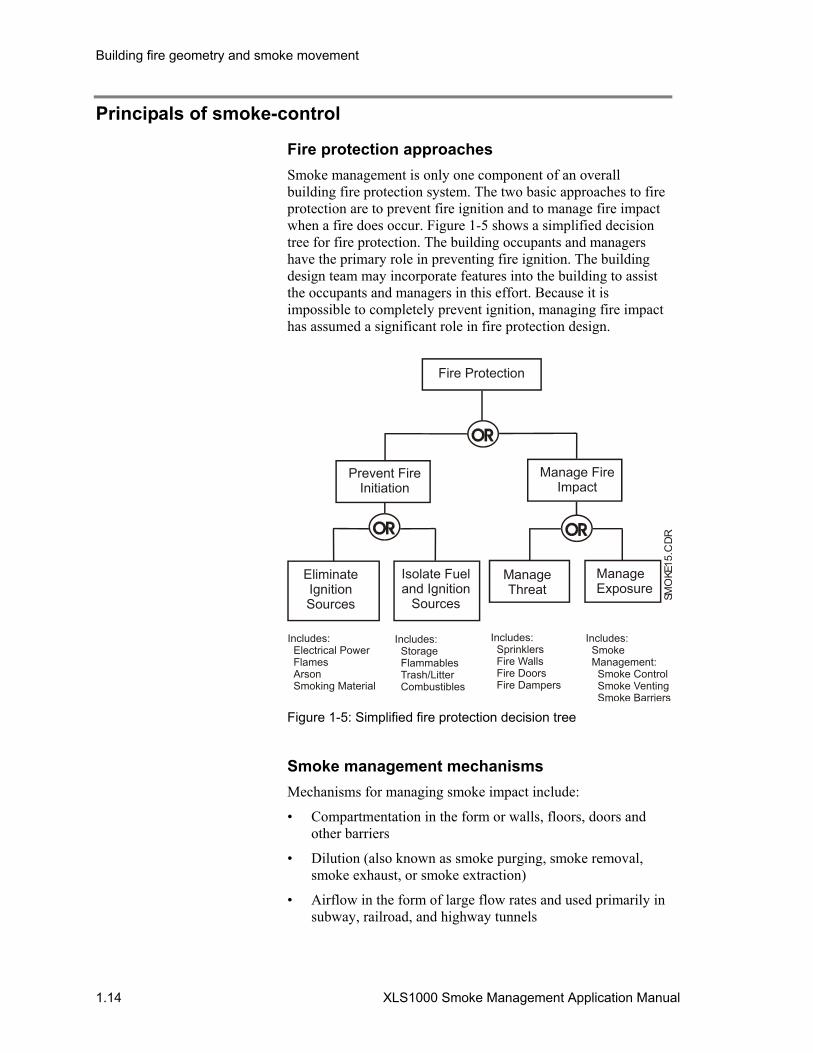
Fire protection approaches Smoke management is only one component of an overall building fire protection system. The two basic approaches to fire protection are to prevent fire ignition and to manage fire impact when a fire does occur. Figure 1-5 shows a simplified decision tree for fire protection. The building occupants and managers have the primary role in preventing fire ignition. The building design team may incorporate features into the building to assist the occupants and managers in this effort. Because it is impossible to completely prevent ignition, managing fire impact has assumed a significant role in fire protection design.
Fire Protection
Prevent FireInitiation
EliminateIgnition Sources
Isolate Fueland Ignition
Sources
Manage Fire Impact
ManageThreat
ManageExposure
Includes: Electrical Power Flames Arson Smoking Material
Includes: Storage Flammables Trash/Litter Combustibles
Includes: Sprinklers Fire Walls Fire Doors Fire Dampers
Includes: Smoke Management: Smoke Control Smoke Venting Smoke Barriers
SMO
KE15
.CD
R
Figure 1-5: Simplified fire protection decision tree
Smoke management mechanisms Mechanisms for managing smoke impact include:
• Compartmentation in the form or walls, floors, doors and other barriers
• Dilution (also known as smoke purging, smoke removal, smoke exhaust, or smoke extraction)
• Airflow in the form of large flow rates and used primarily in subway, railroad, and highway tunnels
Building fire geometry and smoke movement
XLS1000 Smoke Management Application Manual 1.15
• Pressurization using mechanical fans under NFPA 92A
• Buoyancy effects that employ mechanical systems when ceiling heights exceed 33 feet (10m)
Design factors Many factors affect the design of a smoke management system. Before the actual mechanical design of the system can proceed, the potential constraints on the system must be determined and the design criteria established.
Unique factors in the design of a smoke management system include:
• Occupancy type and characteristics • Evacuation plans • Areas of refuge • Occupant density and distribution • Human life support requirements (Medical Facilities) • Detection and alarm systems (exclusive of smoke-control) • Fire department response to fire emergencies in the building • Fixed fire suppression systems • Type of HVAC systems (in place or proposed) • Energy management systems and controls • Building security provisions • Status of doors in a fire emergency • Potential fire sources • Internal compartmentation and architectural characteristics • Building leakage paths • Exterior building temperatures • Wind velocity and effects
All of these factors funnel into a consideration of how much smoke will be present in an expected fire. The amount of smoke, expressed as smoke density, can reduce visibility, trap occupants in the building, prevent escape, and expose occupants over an extended period of time to toxic and irritant gases which could become lethal.
The ASHRAE manual Design of Smoke Management Systems contains guidelines for designers who wish to provide active smoke-control systems for buildings. Smoke-control systems are intended to provide systems that exhaust smoke from the immediate fire area, and provide pressurized outside air to adjacent areas, access corridors, and stairwells. It is fully recognized that this approach would apply more to large HVAC units servicing individual floors or large systems with volume control dampers at each floor. The integrity of the HVAC/smoke management system must be at a level that will maintain safe exit routes with sufficient exiting time for building occupants to either leave or move to designated safe refuge areas.
Building fire geometry and smoke movement
1.16 XLS1000 Smoke Management Application Manual
Smoke zones
A building or area is typically divided into several zones. Zones are delineated by fire or smoke barrier walls or horizontally with floor ceiling assemblies. A smoke zone, as used in this manual, is simply the area where the fire is located. The two basic principals for containing smoke within a smoke zone are pressurization and airflow.
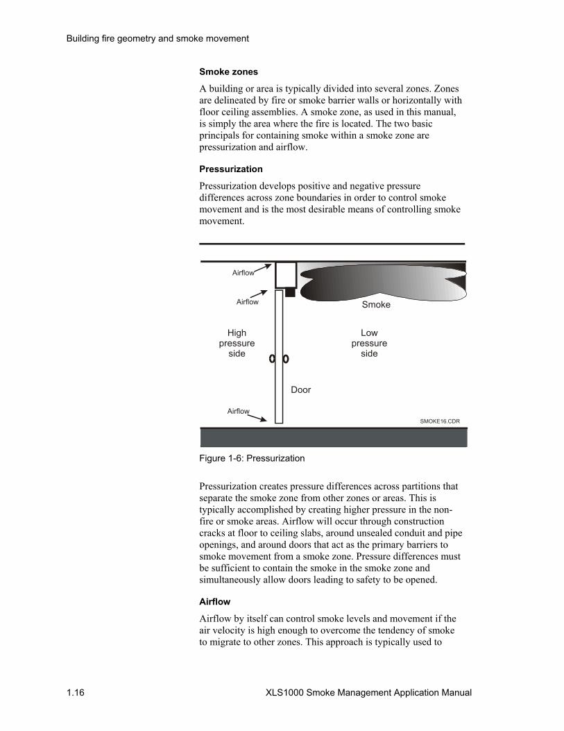
Pressurization
Pressurization develops positive and negative pressure differences across zone boundaries in order to control smoke movement and is the most desirable means of controlling smoke movement.
High pressure
side
Lowpressure
side
Door
Airflow
Airflow
Airflow Smoke
SMOKE16.CDR
Figure 1-6: Pressurization
Pressurization creates pressure differences across partitions that separate the smoke zone from other zones or areas. This is typically accomplished by creating higher pressure in the non-fire or smoke areas. Airflow will occur through construction cracks at floor to ceiling slabs, around unsealed conduit and pipe openings, and around doors that act as the primary barriers to smoke movement from a smoke zone. Pressure differences must be sufficient to contain the smoke in the smoke zone and simultaneously allow doors leading to safety to be opened.
Airflow
Airflow by itself can control smoke levels and movement if the air velocity is high enough to overcome the tendency of smoke to migrate to other zones. This approach is typically used to

Building fire geometry and smoke movement
XLS1000 Smoke Management Application Manual 1.17
prevent the flow of smoke down corridors or through open doorways, as shown in Figure 1-7. The airflow approach to smoke-control requires large quantities of air and is therefore not practical for most applications.
Smoke
Relativelylow airvelocity
Smokeback flow
Relativelyhigh airvelocity Diluted
smokeSMOKE17.CDR
Smoke
Figure 1-7: Airflow
Purging
Purging may be used as a supplement to airflow or pressurization methods in smoke-control systems. When there is a concern over smoke movement through open doors into a protected area, outside air can be introduced into the space. Purging uses an exhaust inlet near the ceiling and a supply inlet commonly in the lower half of a wall. The supply and exhaust points are placed far enough apart to prevent the supply air from blowing directly into the exhaust without the benefit of entraining smoke-filled air. Purging is commonly used in smoke-proof stairwells that contain a vestibule between the occupant space and the stairs.
With any of the methods used for smoke zones, pedestrian door opening forces must be considered. The pressure differences between barriers are important not only in the force to open the door, but also the force necessary to overcome the door closer. NFPA 101, the Life Safety Code establishes a maximum force of 30 lbf (133.35 N) to set a door in motion that is an accepted benchmark for designers. Occupants must be able to open doors leading to escape routes while the smoke-control system is in operation.
Building fire geometry and smoke movement
1.18 XLS1000 Smoke Management Application Manual
Types of systems Smoke management utilizing active and passive methods in combination to modify smoke movement must be engineered into a system and is focused upon property or people protection. While passive methods of smoke management do exist (see NFPA 204), dynamic smoke-control systems using mechanical equipment to meet design goals dominate. NFPA 92B, Guide for Smoke Management Systems in Malls, Atria, and Large Areas, provides methodologies for determining smoke development in large spaces. NFPA 92A, Recommended Practice for Smoke-Control Systems, is used for the design, installation, testing, operation, and maintenance of systems for smoke-control.
An XLS1000 smoke-control system (SCS) when installed and programmed in accordance with this design manual and the criteria set forth by the smoke-control system designer will help to:
• Provide a tenable environment in evacuation routes during the time necessary to evacuate people from the area
• Restrict the movement of smoke from the fire area
• Assist in protecting life and property protection
• Maintain tenable conditions in non-fire areas that will enable fire personnel to conduct search and rescue operations in addition to attacking the seat of the fire
An XLS1000 SCS should be designed, installed, and maintained such that the system will remain effective during evacuation of the protected areas. Other considerations determined by the smoke-control system designer may dictate that a system should remain effective for longer periods. Areas to evaluate in determining XLS1000 SCS integrity are:
• Reliability of power source(s) • Arrangement of power distribution • Location, and methods of protection for XLS1000 system
panels • Building occupancy type
The design, installation, testing, operation, and maintenance of new and retrofitted mechanical air conditioning and ventilation systems for the control of smoke will require the involvement of several interdependent disciplines or parties.
• Building equipment and controls are the responsibility of the system designer. A system designer, as used here, will determine the type of smoke-control system to be used, the size of the expected or design fire, perform tenability calculations, establish and define smoke zones based upon building barriers. The system designer may be an architect,

Building fire geometry and smoke movement
XLS1000 Smoke Management Application Manual 1.19
engineer, or fire protection professional knowledgeable in the theory and application of smoke management and control. The sizing of fans, location of dampers, and establishing of smoke zones is the system designer's responsibility. The system designer will, using a specification, define to the XLS1000 fire/smoke-control system designer how the total system must operate under a fire or smoke condition. The XLS1000 fire/smoke-control system designer should assume total system design responsibility only if qualified.
• Smoke-control system operation is the responsibility of the XLS1000 fire alarm systems designer. The specifications for operation of a smoke-control system will define methods of fire/smoke detection for a particular area and the resulting outputs for smoke removal or control to take place. Control functions performed by an XLS1000 panel include the startup and shutdown of HVAC or exhaust fans, smoke damper closure, and door closure.
• The authority having jurisdiction (AHJ), typically a fire official, is important in the determination of firefighter control station locations and final acceptance and testing of the smoke-control system. The system designer is responsible for effecting smoke removal or control of the completed smoke management system. Involvement of the AHJ early in a project helps to ensure that the system requirements (typically NFPA 92A) will be met by the total system design and establishes prior to design clear pass/fail criteria for a completed system.
Smoke-control systems Systems for controlling smoke movement in a building can be divided into two separate types: shaft protection and floor protection. The vertical transfer of smoke to the upper stories of a building from a fire on a lower floor occurs mostly from shafts versus leakage through openings in floor construction. Vertical smoke spread accounts for 95 percent or more of the upward movement of smoke in high-rise building fires. For either type of smoke-control system, electrical and mechanical equipment or components can be classified as dedicated or non-dedicated. Shaft protection can be further divided into stairwell pressurization systems and elevator hoistway systems. Floor protection encompasses several variations of zoned smoke-control. Use of a particular system or combination of systems is dependent upon building and fire code requirements, as well as specific occupancy and life safety goals established by the system designer.

Building fire geometry and smoke movement
1.20 XLS1000 Smoke Management Application Manual
SHAFT PROTECTIONFLOOR OR AREA
PROTECTION
DEDICATEDSMOKE-CONTROL
SYSTEM
NON-DEDICATEDSMOKE-CONTROL
SYSTEM
ATRIUMS ZONED SMOKE-CONTROL
ELEVATOR HOIST WAY
SYSTEM
STAIRWELLPRESSURIZATION
SYSTEM
COMPENSATEDSYSTEM
SMOKE18.CDR
Figure 1-8: Smoke-control system types
Smoke-control components must be capable of continuous use at the maximum temperatures expected during a fire, based upon calculations performed by the smoke-control system designer. Most smoke-control systems will be designed with a primary goal of maintaining a tenable environment for occupants outside the fire area for zoned smoke-control and within atriums or large spaces. This goal is achieved by exhausting smoke from a building, limiting fire growth, or for atrium smoke management systems, preventing accumulations of smoke below a six-foot height along egress paths.

Building fire geometry and smoke movement
XLS1000 Smoke Management Application Manual 1.21
Dedicated Dedicated smoke-control systems are independent systems for air-movement and are not used for any other purpose under normal building operating conditions. Upon activation, dedicated systems operate specifically to perform a smoke-control function.
Dedicated systems have the following advantages:
• System design and control functions are less likely to be modified during maintenance.
• Operation and control of the system is less complex with system controls typically routed only to the XLS1000 SCS and the firefighter's smoke-control station (FSCS).
• Independent of other building systems, dedicated systems are less likely to be affected by changes in other building systems.
Dedicated systems have several recognized disadvantages:
• Dedicated systems are more costly.
• Component failures may go undetected for a long time.
• Dedicated systems often require more building space for installation.
• Automatic weekly self-testing of dedicated smoke-control systems must be programmed with consideration for weather conditions.
Non-dedicated Non-dedicated smoke-control systems share or use components with other building systems including the HVAC system for a floor, area, or zone. Smoke-control system activation suspends normal operation of HVAC and other shared components for use in achieving smoke-control objectives.
Non-dedicated systems have the following advantages:
• Equipment costs are shared.
• Component failures of equipment needed for smoke-control are more apparent due to their use for daily services.
• Smoke-control system components do not require additional building space.

Building fire geometry and smoke movement
1.22 XLS1000 Smoke Management Application Manual
Non-dedicated smoke-control systems have three recognized disadvantages:
• System control may involve complex interlocks with shared equipment used for HVAC or energy management.
• Inadvertent modification of HVAC controls or equipment affecting smoke-control functionality is more likely to occur.
• Other building system modification may interfere with smoke-control system operation.
HVAC systems Commercial HVAC systems can usually be adapted for smoke-control use. In order to meet smoke-control reliability and tenability criteria established in NFPA 92A, an HVAC system must be capable of supplying outside air to the protected space, returning air from the protected space, and exhausting air from a protected space to the outside.
An HVAC system can be as simple as a fan in a housing (such as a roof-mounted exhaust fans) to a more complex system with ductwork, supply air outlets, return air inlets, fresh air intakes, humidifiers, filters, heating and cooling coils, preheat coils, and dampers.
Commonly used HVAC units
Individual floor units: Air Handling Units serve a single floor or area. Units can have separate supply and exhaust fans. The smoke-control system designer must verify that the units are capable of providing sufficient outside air and an exhaust capability for the expected fire condition.

Building fire geometry and smoke movement
XLS1000 Smoke Management Application Manual 1.23
SMOKE19.CDR
Fan
Fan
Fan
Fan
Figure 1-9: Individual floor units

Building fire geometry and smoke movement
1.24 XLS1000 Smoke Management Application Manual
SMOKE110.CDR
Fan
Fan
Figure 1-10: Induction units for central HVAC system
Induction units: Induction-type air handling units are usually used in conjunction with a central HVAC system, which supplies high-pressure air to the induction units. Induction units are located around the outside of a building and are used to condition the air for areas around the perimeter of a building. Room air is then drawn into the induction unit, mixed with the primary air from the central system, and returned to the room. Induction units servicing a fire area should be shut down or have the primary air from the central system isolated.
Building fire geometry and smoke movement
XLS1000 Smoke Management Application Manual 1.25
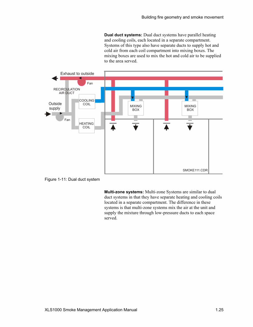
Dual duct systems: Dual duct systems have parallel heating and cooling coils, each located in a separate compartment. Systems of this type also have separate ducts to supply hot and cold air from each coil compartment into mixing boxes. The mixing boxes are used to mix the hot and cold air to be supplied to the area served.
Exhaust to outside
SMOKE111.CDR
HEATINGCOIL
COOLINGCOIL MIXING
BOXMIXING
BOX
RECIRCULATIONAIR DUCT
Fan
Fan
Figure 1-11: Dual duct system
Multi-zone systems: Multi-zone Systems are similar to dual duct systems in that they have separate heating and cooling coils located in a separate compartment. The difference in these systems is that multi-zone systems mix the air at the unit and supply the mixture through low-pressure ducts to each space served.
Building fire geometry and smoke movement
1.26 XLS1000 Smoke Management Application Manual
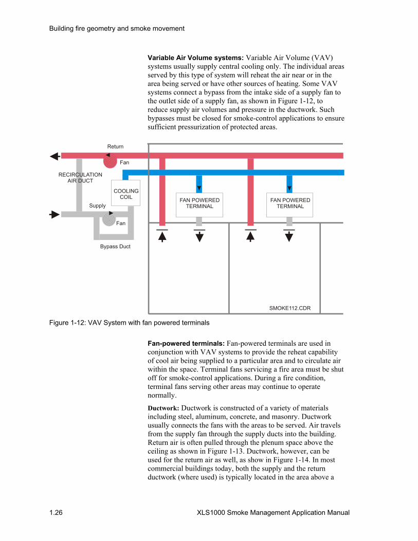
Variable Air Volume systems: Variable Air Volume (VAV) systems usually supply central cooling only. The individual areas served by this type of system will reheat the air near or in the area being served or have other sources of heating. Some VAV systems connect a bypass from the intake side of a supply fan to the outlet side of a supply fan, as shown in Figure 1-12, to reduce supply air volumes and pressure in the ductwork. Such bypasses must be closed for smoke-control applications to ensure sufficient pressurization of protected areas.
SMOKE112.CDR
COOLINGCOIL
RECIRCULATIONAIR DUCT
FAN POWEREDTERMINAL
FAN POWEREDTERMINALSupply
Return
Fan
Fan
Figure 1-12: VAV System with fan powered terminals
Fan-powered terminals: Fan-powered terminals are used in conjunction with VAV systems to provide the reheat capability of cool air being supplied to a particular area and to circulate air within the space. Terminal fans servicing a fire area must be shut off for smoke-control applications. During a fire condition, terminal fans serving other areas may continue to operate normally.
Ductwork: Ductwork is constructed of a variety of materials including steel, aluminum, concrete, and masonry. Ductwork usually connects the fans with the areas to be served. Air travels from the supply fan through the supply ducts into the building. Return air is often pulled through the plenum space above the ceiling as shown in Figure 1-13. Ductwork, however, can be used for the return air as well, as show in Figure 1-14. In most commercial buildings today, both the supply and the return ductwork (where used) is typically located in the area above a

Building fire geometry and smoke movement
XLS1000 Smoke Management Application Manual 1.27
suspended ceiling. Return air ductwork is required from the smoke zone boundary to exhaust fans when routed through other zones.
SMOKE113.CDR
Plenum
Duct
Figure 1-13: Supply ductwork with plenum return
SMOKE114.CDR Figure 1-14: Ducted return
Stairwell pressurization systems Stairwell pressurization systems are built with the intent of keeping stairs clear of smoke in order to assist in the evacuation of occupants. Stairwell pressurization systems are commonly dedicated smoke-control systems. Activation of stairwell systems can be by automatic or manual means.

Building fire geometry and smoke movement
1.28 XLS1000 Smoke Management Application Manual
Stair pressurization systems can be from a single-injection point into the tower. Single-injection systems are commonly used for eight or fewer stories. Multiple injection systems provide several supply inlets in the stairwell. Compartmentation of the stairwell can also be used in a pressurized design to maintain stair tenability. Pressurization systems may operate throughout the fire event, offering refuge for firefighters as they enter or leave the fire floor.
Stairwellcompartments
SM
OK
E11
5.C
DR
Fan Figure 1-15: Compartmentaton of a pressurized stairwell
A fire in a multi-story building will develop a positive pressure in the fire area until ventilation occurs, often due to the opening of a door or the failure of window glass. The positive pressures developed by a fire can enter a stair as occupants leave the fire floor and reduce the usefulness of the stair for escape. The design objective of achieving a higher pressure in the stair than is found on the fire floor is usually achieved by a single dedicated fan in the stairwell. Life safety and fire codes require stairwells to be isolated from the building they serve, making the use of shared building HVAC systems unlikely or prohibited. Dedicated HVAC systems for stairwell pressurization systems are also used with modulating dampers controlled by static sensors at each doorway or at selected points in a stairwell.
Building fire geometry and smoke movement
XLS1000 Smoke Management Application Manual 1.29
For pressurizing a stairwell, the smoke-control system designer must define the number of doors expected to be open at any one time and design air flows which compensate for the open doors. If more than the expected or design number of doors is opened, the pressure in the stairwell may drop below that of the fire floor and smoke will be able to enter the tower.
Power requirements for smoke-control system operation must consider the total number of systems or zones in operation. For example, if there are two stairwells with pressurization, they will both operate in a fire event and power must be available for both tower systems. If a smoke-control zone on the fire floor will also operate, then the three separate smoke-control systems must be powered and operable from the FSCS.
Automatic operation of one of a building's fire alarm systems should cause all stair pressurization fans to start. Where an engineering and life safety analysis determines that the configuration of the building is such that only certain stairs need pressurization, programming of the smoke-control system will need to be tailored to various fire scenarios.
A smoke detector should be provided in the air supply to the pressurized stairwell. Smoke drawn into the stairwell from the exterior of the building will be detected and fans will then shutdown. Detectors selected for fan flow monitoring should be within the air velocity ranges specified in the detector's installation sheet.
The FSCS must contain a manual override, to be operated by an authorized person, to restart fans should they shutdown due to the operation of smoke detectors installed in the stairwell. The authorized person may determine that a lesser hazard exists from smoke entering the fan than smoke migrating into the tower from the fire floor and override fan shutdown based upon exterior smoke entry.

Building fire geometry and smoke movement
1.30 XLS1000 Smoke Management Application Manual
Lessons learned in fire and smoke movement: MGM Grand Hotel
Details Event
Location: Las Vegas, NV Date: November 1980 Fatalities: 85 Injuries: 600
The complex consisted of 26 stories of guestrooms and a ground level complex with a casino, theatres and convention facilities. Each wing contained a pressurized stairwell with a mechanically ventilated vestibule (smoke-proof tower).
The fire started in the first floor restaurant and then moved into the casino. Smoke spread was through ceiling plenum spaces to vertical shafts that allowed smoke spread to the high-rise tower. Vertical openings included seismic joints, interior stairs, toilet exhaust shafts and pipe chases. The elevator shafts allowed smoke spread to upper floors via open elevator doors on the casino level. Sixty-one of the fatalities were in the hotel tower between floors 16 and 26 and were caused by smoke inhalation. No smoke-control system was in place at the time of the fire.
Vestibules: Stairwells can also be built with a vestibule that may include an air handling system. The vestibule may serve a pressurized stair or it can be in lieu of a pressurized stair, operating under the same criteria as a pressurized stairwell for smoke-control. Even non-pressurized vestibules have the advantage of two doors from the building interior to a stair that can help to limit smoke migration into a stair. Vestibule pressurization controls are addressed in much the same manner as stair pressurization systems by the smoke-control system.
Elevator smoke-control Elevator smoke-control systems are of two types. The first focuses upon providing tenability and survivability of the elevator system in order that it can be used for occupant evacuation. Figure 1-16 diagrams two design alternatives. Exhaust of the fire floor, smoke-tight elevator lobbies, and the closing of elevator doors after automatic recall are other design alternatives which are less often chosen. Elevators traditionally have not been used for fire evacuation due to the “chimney effect” of the shafts in a fire.
In the last decade, due in part to increased demands for egress of non-mobile occupants and driven by the American with Disabilities Act (ADA), elevators have increasingly been looked

Building fire geometry and smoke movement
XLS1000 Smoke Management Application Manual 1.31
upon as a possible avenue for fire escape. First, Canada developed standards for “hardened” elevators for egress and then in the US the NFPA Life Safety Code included elevators as an alternate egress component from areas of refuge. Smoke-control for elevators used as an egress system components must provide tenability for the expected time needed for evacuation.
The second type of elevator smoke-control system is intended to prevent or limit smoke flow to other floors by way of the hoistway. Elevators without enclosed lobbies must have a smoke-control-system that develops a pressure difference within the hoistway, which is greater than the sum of the fire and other building effects. The smoke-control system designer will calculate pressures, flow rates, and vent sizes for the elevator shaft to determine fan size.
Elevator recall is based upon ASME/ANSI117.1, Safety Code for Elevators and Escalators. The standard requires that elevator doors open and remain open after elevators recalled. This requirement results in a large opening into the elevator hoistway, greatly increasing airflow requirements for pressurization. NFPA 80, Standard for Fire Doors and Windows, permits closing of elevator doors after a predetermined time when required by the AHJ. Local requirements for the operation of pressurized shafts should therefore be determined and incorporated into the system design.
Lessons learned in fire and smoke movement: John Sevier Center
Details Event
Location: Johnson City, TN Date: December 25, 1989 Fatalities: 16 Injuries: 40
A fire in a first floor apartment of the 10-story building spread through an open door, into the corridor, and quickly involved the entire first floor. Smoke migration to upper floors via the recalled elevator and vertical shafts resulted in 15 deaths due to smoke inhalation located above the fire floor.

Building fire geometry and smoke movement
1.32 XLS1000 Smoke Management Application Manual
Lobby Floor area
Pressurized elevator shaft system
Lobby
Lobby
Pressurized lobby system
SMOKE116.CDR
Fan
Fan
Lobby Floor area
Figure 1-16: Elevator pressurization systems
Table 8.11 of NFPA's Smoke Movement and Control in High-rise Buildings contains both elevator shaft and lobby pressurization system calculation formulas. John M. Klote, who worked with the author of this NFPA reference book, includes the same methodologies and several examples, in his ASHRAE book, Design of Smoke Management Systems.
Elevator recall systems return the elevator(s) to the lobby or an adjacent floor when smoke is detected in an elevator lobby or when the fire alarm system is activated. Elevator doors can open at the recall location and remain open or revert to the closed position. The smoke-control system designer must adjust airflow for the door position.

Building fire geometry and smoke movement
XLS1000 Smoke Management Application Manual 1.33
Lessons learned in fire and smoke movement: First Interstate Bank of California
Details Event
Location: Los Angeles, CA Date: May 1988 Fatalities: 1 Injuries: None
A 62-story office tower with smoke detectors on each floor. The fire started in the open-plan office area located on the 12th floor. Fire spread continued upward for four floors where manual firefighting stopped the fire's progress. Fire spread was primarily along the exterior of the building and around floor slabs. The fire progressed at a rate of 45 minutes per floor with total burnout of each floor taking approximately 90 minutes.
Security personnel reset the initial smoke detector alarm from the fire floor and then the three smoke detectors which went into alarm several minutes later on the floor. Six minutes after the initial alarm, detectors were operating from the 12th to 30th floors. An employee sent to investigate died when the elevator opened on the fire floor.
Investigators determined that the service elevator acted as a major avenue for smoke spread to all floors. No smoke-control system was installed in the building.
Zoned smoke-control systems Larger area or multiple floored buildings will subdivide the smoke-control system into zones based upon an expected fire scenario.
Activation of a smoke-control zone will be by automatic or manual means. A smoke detection system will automatically activate the XLS1000 smoke-control system. Detector spacing should follow spacing of smoke detector requirements contained in the Signature Series Intelligent Smoke and Heat Detectors Bulletin (P/N 270145). The Bulletin also contains design information on detector placement with respect to stratification, partitions, exposed solid joists, exposed beams, sloped ceilings, and high air-movement areas. Automatic actuation of a zoned smoke-control system can simultaneously exhausts a fire/smoke area and supply air to other areas. Detector locations, however, must coordinate with the operation of the smoke-control zone to detect smoke before it migrates to another zone. Smoke-control system programming will limit automatic activation to the first zone that detects smoke.
A waterflow switch or heat detector serving a smoke zone can be used to activate the zoned smoke-control system where all piping
Building fire geometry and smoke movement
1.34 XLS1000 Smoke Management Application Manual
or wiring of the devices is in the smoke zone. For example, a sprinkler system serving an atrium cannot have branch sprinkler lines serving an office area adjacent to the atrium and not a part of the same smoke-control zone.
Atriums Initially, fires in atriums (or large spaces) will perform like fires in outside areas due to the size and height of the space where the fire occurs. Upper levels of high ceilings or tall atriums collect heat and smoke with little or no downward radiation. Atriums and large spaces cannot easily restrict the movement of smoke using barriers or overcoming fire pressures. Common atrium or large space areas using smoke management systems include shopping malls, convention centers, airport terminals, sports arenas, and warehouses.
For large spaces, smoke management consists of exhausting smoke from the space. Exhausting smoke tends to restrict smoke spread to a plume above the fire and a smoke layer just below the ceiling of the space. The exhaust approach creates a lower level “smoke-free” layer that allows occupants to safely egress and for firefighters to see and attack the seat of a fire more readily.
Providing smoke management for large spaces is a unique challenge for two reasons. First, without any barriers in the interior, extensive smoke propagation occurs readily throughout the entire space. Consequently, a significant number of people in the space may be exposed to the smoke. Further, a substantial portion of the space can become contaminated by the smoke, resulting in significant property damage.
Second, large unprotected openings between the atrium and adjacent spaces can result in fire and smoke movement into the atrium due to a fire outside the atrium. Adjacent spaces, such as stores in a shopping mall, are called communicating spaces and may open directly to the atrium or may connect through a corridor or another open passageway. In the last several years code limitations on the number of levels with communicating spaces open to an atrium have been changed to allow all levels in an atrium to have open communicating spaces. Required airflow for smoke venting in an atrium or large space must consider the effect of communicating space fires.

Building fire geometry and smoke movement
XLS1000 Smoke Management Application Manual 1.35
Lessons learned in fire and smoke movement: Hyatt Regency O'Hare Hotel
Details Event
Location: Rosemont, IL Date: April 1973 Fatalities: None Injuries: 1
A 10-story hotel with rooms opening to a central atrium. The fire started in the non-sprinklered nightclub on the first floor at 4:30 a.m. The atrium filled with smoke. The smoke exhaust system failed to operate because a switch to the system was turned off. Some occupants escaped along open balconies in the atrium to enclosed stairs in the early stages of the fire. Other occupants took refuge on exterior balconies or remained in their rooms with the balcony doors open. The fire demonstrated that rapid smoke generation and spread in an atrium quickly traps occupants.
How a large space functions, location of egress routes, and the development of hazardous conditions from expected fire scenarios demands a tailoring of smoke management systems for each application. However, the technical fundamentals of smoke production and spread are the same for all of these spaces. A shopping mall smoke management design will focus on assuring egress paths are available, while a warehouse smoke management design will focus on the stored materials.
Parameters that may have an impact on the design of a smoke management system in a large space include:
• Ceiling height • Fuel load • Use of the space • Separation of communicating spaces from the protected
space

Building fire geometry and smoke movement
1.36 XLS1000 Smoke Management Application Manual
Smoke-control system components
Initiating circuits Output circuits
ManualControls
Manualpull stations(Stairwells only)
Detectors
Automaticsprinklerand waterflowswitches
Firefighter's smoke-control station (FSCS)
Fans
Dampers
Door Closers
SMOKE117.CDR
Limit switches & air flow monitoring
FSCS series annunciator
3-LCD LED/switchmodule
Figure 1-17: Input and output components
Controls The smoke-control system must fully coordinate smoke-control system functions between the:
• XLS1000 fire protective signaling system • Automatic sprinkler system • FSCS • Systems related HVAC energy management • Building smoke-control equipment.
Operation of the smoke-control system either as a component of the XLS1000 fire alarm system or as a stand-alone XLS1000

Building fire geometry and smoke movement
XLS1000 Smoke Management Application Manual 1.37
smoke-control system panel from a centralized location will be the most common applications.
Fire department suppression mobilization for large buildings may be from a loading dock in a high-rise building or at the main entrance of large buildings. An FSCS at the point of fire department mobilization or near the exterior of the building will often be required by codes or standards in addition to the XLS1000 smoke-control system.
Building main control/security center
Larger, more complex buildings and office or educational campuses contain centralized energy management and security centers. These control points for building systems or access may be located off the main lobby of a high-rise, in the center of a large building, or freestanding on a campus. The location and monitoring of the Fire Alarm Control Panel from these points is both practical and common. Installation of the XLS1000 smoke-control system in one of these centers is logical. The trained personnel who monitor other fire and building systems can also be trained for smoke-control system monitoring and operation. The building's main control or security center could also serve as the location of the FSCS, if acceptable to the AHJ.
Firefighter's smoke-control station (FSCS)
The FSCS, where required, is located according to direction from the AHJ. The FSCS must provide full monitoring and manual control capability over all smoke-control system functions including a graphical panel.
The FSCS should be designed to have the highest priority control over all smoke-control systems and equipment. Where manual controls are also provided at other building locations (such as the Main Control/Security Center) for use of smoke-control systems, the control mode selected from the FSCS should prevail. The design of the FSCS must be such that control actions from this point will override or bypass other building controls such as Hand-Off-Auto and Start/Stop switches located on fan motor controllers, freeze detection devices, and duct smoke detectors. FSCS controls should not override or bypass devices and controls intended to protect against electrical overloads, provide for personnel safety, or prevent major system damage. These include overcurrent protection devices, electrical disconnect switches, high-limit static pressure switches, and combination fire/smoke dampers beyond their degradation temperature classifications. FSCS non-dedicated system fan motor controller switches do not need to be bypassed when:
• Located in mechanical or electrical equipment rooms • Inaccessible to the general public

Building fire geometry and smoke movement
1.38 XLS1000 Smoke Management Application Manual
• Operation of such a switch will result in a trouble condition at the building's main control center
The XLS1000 SCS, to be effective, should include an FSCS series annunciator with a building diagram that indicates the type and location of all smoke-control equipment. The building areas affected by the equipment, including barrier walls, should also be clearly indicated (Figure 1-17).
The actual status of system components that are activated or capable of activation for smoke-control should be clearly indicated at the FSCS series annunciator. Status indication is for on and off status of each individual fan having a capacity of 2000 cfm (944 L/s) or more and used for smoke-control. The “ON” status should be sensed by pressure difference as a confirmation of airflow. Damper position status is also often required by UUKL and NFPA 92B.
HVAC system controls
Initial design of HVAC system controls or modification of existing HVAC controls to incorporate smoke-control system requirements must include assigning the highest priority to the smoke-control mode.
Dedicated smoke-control systems, while not utilizing HVAC fans and controls, will sometimes require the shutdown of the building HVAC equipment in addition to the closing of dampers interconnected to the HVAC system.
Non-dedicated fire systems will use HVAC components and control systems. HVAC control systems use pneumatic, electric, electronic, and programmable logic-based control units. All of these control systems can be adapted to provide the necessary logic and control sequences to configure HVAC systems for smoke-control. Programmable electronic logic or microprocessor based control units for HVAC systems which also provide other building control and monitoring functions are readily adapted to provide the necessary logic and control sequences for an HVAC system's smoke-control mode of operation.
Smoke-control system activation and deactivation Smoke-control system activation is the initiation of the operational mode of a smoke-control system. Deactivation is the cessation of the operational mode of the smoke-control system and return of HVAC control to the building environmental control center. Smoke-control systems usually are activated automatically but can be manually initiated under conditions deemed appropriate as a part of the smoke-control system design. Under all operating conditions, the smoke-control system must be capable of manual override.

Building fire geometry and smoke movement
XLS1000 Smoke Management Application Manual 1.39
Loss of building power should be evaluated to determine if the smoke-control system design would function as intended. The evaluation must consider the position (open or shut) of smoke dampers upon loss of power and when the fan systems the dampers served are shutdown.
Automatic activation or deactivation of a smoke-control system includes all initiating circuit action that results in the operation of one or more smoke-control zones without manual intervention. Automatic activation will usually come from smoke detectors and waterflow switches.
Smoke-control system activation should begin immediately upon receipt of an activation command. Sequencing of smoke-control components (fans, dampers, ducts, and louvers) is necessary to prevent physical damage to the equipment. Over-pressurization of a duct due to early or improper damper operation could result in damage to the duct and an inability to effectively control smoke in a zone.
NFPA 92A, Recommended Practice for Smoke-Control Systems, establishes the maximum response time for individual components to reach a fully operational mode. Fans must reach the specified flow rate within 60 seconds and confirm the state has been reached at the smoke-control panel and the FSCS. Completion of smoke damper travel to either the fully open or the fully closed state must be accomplished within 75 seconds of signal initiation.
Note: Local codes, like UBC, may specify other times. Check all applicable codes and use the time limit required.
Initiating circuits Smoke-control system initiating circuits may contain the same alarm initiating devices found in a standard XLS1000 fire alarm system and Initiating Device Circuit (IDC). Alarm Initiating Devices used for smoke-control may also serve a dual-purpose, initiating alarm notification or control functions required under NFPA 72. A smoke-control system initiating device, when activated, initiates predetermined system sequences.
Detection
Smoke-control system initiation using smoke detectors is most common. Since the goal of smoke-control systems is most often to maintain tenability in a zone or space, heat or flame-type detection is not considered responsive enough for use in a smoke-control system. Heat detectors in maintenance or similar rooms incidental to the area protected or locations where smoke detectors cannot be effectively installed may be connected to the smoke-control system.
Building fire geometry and smoke movement
1.40 XLS1000 Smoke Management Application Manual
Detection using either photoelectric or ionization spot type smoke detectors should be based upon the space protected. Smoke development and travel are influenced by ceiling configuration and height, burning characteristics of materials, fuel arrangement, room geometry, and HVAC systems installed. Some large volume spaces, such as atriums, have been reported to experience temperatures of up to 200 °F (93.3 °C) because of solar loads. Detectors in these areas need to be capable of operating in this day-to-day environment. Installation sheets for detectors contain operating temperature ranges for detectors. Signature Series Smoke detectors should be installed in accordance with the requirements contained in the Signature Series Intelligent Smoke and Heat Detectors Applications Bulletin (P/N 270145).
Concerns over smoke stratification and detector access in large or high ceiling areas, such as atriums, is increasingly leading designers to specify projected beam-type smoke detectors. Projected beam detectors work on the principle of light obscuration. A beam of infrared light is transmitted across the protected area and is monitored by a receiver. Smoke particles entering the beam path can either absorb or scatter the beam of light, causing a reduction in light received. When the reduction in light received reaches a threshold, an alarm signal is generated. Since both absorption and scattering of light cause a reduction in the light sensed at the receiver, projected beam detectors work well for both smoldering and fast-flaming fires. Projected-beam detectors are normally installed parallel and within 20 inches (0.508 m) of the ceiling except when high ceilings or smoke stratification are a design consideration. Projected beam detectors have an operating range of 30 to 330 feet (9.144 to 100.584 m).
Manual pull stations
Manual pull stations are placed in buildings for occupant use in reporting fires and notifying other occupants. Manual pull stations are not normally used to activate smoke-control systems, but may be used for stairwell pressurization systems. With manual pull stations there is a greater likelihood of a person signaling an alarm from a station outside the smoke zone in which the fire is occurring and thereby pressuring and venting the wrong areas.
Automatic sprinkler and specialized extinguishing systems
The same criteria that dictate the installation of a smoke-control system are likely to also dictate the installation of an automatic extinguishing system. Most model codes will require automatic sprinklers for large or tall buildings. In the design of the smoke-control systems, the size of the expected fire must be determined

Building fire geometry and smoke movement
XLS1000 Smoke Management Application Manual 1.41
in order to establish exhaust flows for the smoke generated. Automatic sprinkler systems are designed to contain or control fires, thus limiting the size of an expected fire and the amount of smoke generated. Smoke-control system designers utilize the limiting of fire size and spread due to automatic sprinklers as an important element in sizing HVAC systems and fans for smoke-control.
Automatic sprinkler systems can be utilized to activate a smoke-control zone, provided the flow switch for the sprinkler system serves only fire sprinklers in the smoke-control zone. For new buildings, the coverage areas of sprinkler systems must be coordinated with smoke zone areas to ensure applicability.
Manual controls
For smoke control, manual activation or deactivation refers to the means available to an authorized person to activate one of the smoke-control functions. Manual fire alarm pull stations are not in this category. Manual controls will be at the FSCS in a location directed by the AHJ.
Smoke-control output circuits Smoke-control system output circuits may contain some of the same output modules and devices found in a standard XLS1000 fire alarm system. Output commands for a smoke-control zone include the startup or shutdown of fans, damper operation, vent or louver operation, and door or barrier operation. Sequencing of each action is critical in the proper functioning of a smoke-control system. Dampers may need to reach fully open or fully closed position prior to fan startup. Fans may also need to rundown or stop prior to damper movement.
Fans
HVAC fans are classified as either centrifugal or axial. Fan performance and economics are major factors in the type of fan for an application. Forward-curved fans are used for low-pressure applications including residential furnaces and packaged air-conditioning equipment. Airfoil and backward-curved fans are used for general-purpose HVAC applications, and airfoil fans are usually limited to large systems where the energy savings are significant. Radial fans are used when high pressures are needed. New building installations using fans for smoke-control will consider the emergency operation parameters when selecting the HVAC system fans.
Centrifugal fans: Centrifugal fans are subdivided into forward-curved, backward-curved, and airfoil. Forward-curved centrifugal fans rotate at a relatively low speed. They are generally used to produce high flow rates and low static

Building fire geometry and smoke movement
1.42 XLS1000 Smoke Management Application Manual
pressures. Backward-curved fans rotate at about twice the speed of forward-curved fans and have a higher efficiency. Both forward-curved and backward-curved impeller blades are single-width blades.
*OUTLET
AREA
AIRFLOW
AIRFLOW
*SMOKE118.CDR
Bladesfins
Direction ofimpeller rotation
Impellerwheelrotor
Cut off
Figure 1-18: Centrifugal Fans
Airfoil fans: Airfoil fans are simply backward-curved fans with blades of varying thickness to improve fan efficiency. Airfoil blades are based upon the same technology that is used to design airplane wings. Tubular centrifugal fans are an exception to the classification. They have single width impeller blades and straightening vanes at the discharge. Tubular centrifugal fans are used in low-pressure HVAC applications, often as return air fans.
StreamlineInlet
Air out
Air in
SW centrifugalfan wheel
Smoke119.CDRStraightening Vanes
Figure 1-19: Tubular Centrifugal Fan
Axial fans: Axial fans are subdivided as propeller fans, tubeaxial fans, and vaneaxial fans. Axial fans are designed to achieve high flow rates at low pressures. Common uses for axial fans include kitchen and rest room exhaust, stairwell or elevator pressurization, and space ventilation. Propeller fans are
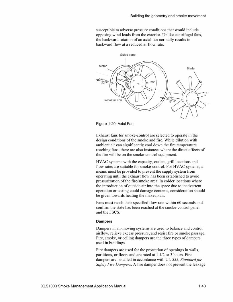
Building fire geometry and smoke movement
XLS1000 Smoke Management Application Manual 1.43
susceptible to adverse pressure conditions that would include opposing wind loads from the exterior. Unlike centrifugal fans, the backward rotation of an axial fan normally results in backward flow at a reduced airflow rate.
AIRFLOWIN
AIRFLOWOUT
SMOKE120.CDR
Guide vane
MotorBlade
Figure 1-20: Axial Fan
Exhaust fans for smoke-control are selected to operate in the design conditions of the smoke and fire. While dilution with ambient air can significantly cool down the fire temperature reaching fans, there are also instances where the direct effects of the fire will be on the smoke-control equipment.
HVAC systems with the capacity, outlets, grill locations and flow rates are suitable for smoke-control. For HVAC systems, a means must be provided to prevent the supply system from operating until the exhaust flow has been established to avoid pressurization of the fire/smoke area. In colder locations where the introduction of outside air into the space due to inadvertent operation or testing could damage contents, consideration should be given towards heating the makeup air.
Fans must reach their specified flow rate within 60 seconds and confirm the state has been reached at the smoke-control panel and the FSCS.
Dampers
Dampers in air-moving systems are used to balance and control airflow, relieve excess pressure, and resist fire or smoke passage. Fire, smoke, or ceiling dampers are the three types of dampers used in buildings.
Fire dampers are used for the protection of openings in walls, partitions, or floors and are rated at 1 1/2 or 3 hours. Fire dampers are installed in accordance with UL 555, Standard for Safety Fire Dampers. A fire damper does not prevent the leakage

Building fire geometry and smoke movement
1.44 XLS1000 Smoke Management Application Manual
of smoke through the opening and is normally released by a fusible link.
Smoke dampers resist the passage of smoke and protect openings in smoke barriers or as a part of engineered smoke-control systems. Smoke dampers are installed in accordance with UL 555S, Standard for Safety Leakage Rated Dampers for Use in Smoke-Control Systems. Combination fire/smoke dampers will have a fire resistance rating and meet both UL 555 and UL 555S.
Ceiling dampers or other methods for protecting openings in floor/roof-ceiling assemblies are installed in accordance with UL 555C, Standard for Safety Ceiling Dampers.
Fire and ceiling dampers are designed to close upon the operation of a fusible link. When dampers are part of an engineered smoke-control system the temperature rating of the fusible links must be 50 degrees above the maximum smoke-control system designed operating temperature with some additional qualifiers found in UL 555S.
With the remote operation of dampers for the engineered smoke-control system, dampers must have provisions that allow them to re-close automatically upon reaching the damper's maximum degradation temperature as defined in UL 555S.
Completion of smoke damper travel to either the fully open or the fully closed state must be accomplished within 75 seconds and be confirmed at the FSCS.
Note: Local codes may require different response times for smoke dampers. See System Response Time in Chapter 3.
Louvers and vents
Various combinations of louvers, vents, and non-rated dampers can be used as a part of a smoke-control system. These venting methods are used to prevent over-pressurization of stairwells, elevator shafts and smoke zones. Vents can provide relief using barometric dampers with adjustable counterweights or electric or pneumatic motor-operated dampers.
Venting in stairwell and some atrium smoke-control systems may use side-swinging doors that open to the exterior in lieu of louvers or vents. Exterior doors produce a constant-supply air rate, a recognized advantage in the design of stair systems on several fronts, including a requirement in the Supplement to the National Building Code of Canada. Exterior door opening is a method of reducing pressure fluctuations in the stairwell in the same way in which louvers and vents are used.
Movable louvers may be used in elevator or stairwell pressurization systems and must be interconnected to the smoke-control system to ensure that they open in the proper sequence.

Building fire geometry and smoke movement
XLS1000 Smoke Management Application Manual 1.45
Movable louvers may also be used for some building or zoned smoke-control systems. For whichever device is selected, there should be a capability to close the opening should smoke begin to enter through it.
Doors for makeup air
The simplest method of introducing makeup air into an area is via direct openings to the outside using doors and louvers, which can be opened upon system activation. For new construction, the architectural designer, in concert with the smoke-control system designer, can place these opening below the expected smoke layer. For locations where such openings are impractical, a powered supply system will likely be used.
Door/wall closers
In the last decade, several manufacturers have developed rolling or bifold door and wall systems, which can be used to create a smoke zone, isolate elevator shafts, lobbies, or areas of refuge. Smoke barriers, other than side swinging doors, are supplied by a small number of manufacturers. The Won-Door Co. has received a door and a wall rating for their bifold system; McKeon Rolling Door has a rolling/swinging door combination; and SmokeGuard Corp. has an elevator opening protective. Listing directories for buildings materials contain specifics about these products. Each of these barrier systems depends upon smoke detection for operation and where used is an important part of establishing and maintaining smoke-control zones.
Panel and component operation
Panel functions
This chapter provides general information on the techniques used to evaluate the physical characteristics of smoke movement through buildings as a basis for designing smoke-control systems. Mechanical system components consisting primarily of fans and dampers are determined, sized, and located by the smoke-control system designer. The smoke-control system designer is an engineer, architect, or competent person, usually on the building owner's design team. The XLS1000 Smoke-Control System Designer should not establish smoke zones, and airflow requirements as a part of the design unless they are competent in HVAC system and smoke movement analysis. The XLS1000 smoke-control system panel functions are therefore based upon requirements established by the smoke-control system designer.
Detection of a fire or smoke condition is the same for an XLS1000 smoke-control system panel and the standard

Building fire geometry and smoke movement
1.46 XLS1000 Smoke Management Application Manual
XLS1000 fire alarm panel. Outputs from the smoke-control system are focused upon two areas:
• Removing or reducing smoke from an area or zone • Compartmentalizing a smoke zone
Smoke-control system functions do not include the alerting of the occupants or fire department of the event; this is performed by the fire alarm panel. An XLS1000 smoke-control system can be a stand-alone panel with its own 3-CPU1 Central Processor Module, Primary Power Supply Module (3-PPS/M), Local Rail Modules (LRM), Control/LED Displays, and related controllers. Alternately, an XLS1000 smoke-control system can be housed in an XLS1000 fire alarm panel sharing 3-CPU1, 3-PPS/M, and other panel functions. The decision to incorporate smoke-control system functions into the XLS1000 fire alarm panel should be accepted as a part of the design process by the building owner and local AHJ requirements. There are some jurisdictions currently requiring a stand-alone smoke-control system under their building and fire codes.
Control system supervision and instrumentation
Every smoke-control system must have a means of ensuring it will operate if needed. The means will vary according to the complexity and importance of the system. Supervision devices can include:
• The presence of operating power downstream of all circuit disconnects
• End-to-end supervision of wiring, equipment, and devices in a manner that includes provisions for positive confirmation of activation, periodic testing, and manual override operation
• Positive confirmation of fan activation by means of duct pressure, airflow, or equivalent sensors that respond to loss of operating power, problems in the power or control circuit wiring, airflow restrictions, and failure of the belt, shaft coupling, or motor itself
• Positive confirmation of damper operation by contact, proximity, or equivalent sensors that respond to loss of operating power or compressed air, problems in the power control circuit, or pneumatic lines, and failure of the damper actuator, linkage, or damper itself
• Other devices or means as appropriate
Energy management systems
Energy management systems, particularly those that cycle supply, return, and exhaust fans for energy conservation, must be overridden when they control or may operate in conflict with the smoke-control system. Smoke-control is an emergency mode of

Building fire geometry and smoke movement
XLS1000 Smoke Management Application Manual 1.47
operation and is to take priority over all energy management and other non-emergency control modes.
Materials
Materials used for systems supplying smoke-control are to conform to NFPA 90A, Standard for the Installation of Air Conditioning and Ventilating Systems, and its referenced standards.
Duct materials should be designed and selected to convey hot smoke, withstand any additional pressure (either positive or negative) by the supply and exhaust fans when operating in a smoke-control mode. Ducts must maintain their structural integrity during the period when they are designed to operate. Special high-temperature ratings for smoke exhaust fans are not normally necessary.
Electrical power requirements
All electrical installations must meet the requirements of NFPA 70, National Electric Code, in addition to building code requirements. Normal electrical power serving air conditioning systems will generally have sufficient reliability for non-dedicated zoned smoke-control systems.
Standby power for dedicated smoke-control systems and their control systems should be adequate for the expected duration of a fire event.
Programming functions
Regardless of the type of smoke-control system installed, the control and programming device functions will fall into three general categories.
• The operation of fans - turning ON or OFF
• The operation of compartmenting components (dampers, doors, louvers, walls, or windows)- to OPEN or CLOSE
• Auto is the placement of HVAC system components in their normal non-fire condition.
From the two control categories the monitoring or status of smoke-control equipment will also be needed or required. Verification of devices results in a confirmation of:
• An ON (fan) or OPEN (dampers, etc.) condition • An OFF (fan) or CLOSE(D) (dampers, etc.) condition
Control and Monitoring Functions will fall into one of the categories shown in Table 1-1 for fans or compartmenting devices. Monitoring will take the form of an LCD, or Annunciator LED. Table 1-1 provides a list of control actions and the devices they monitor.

Building fire geometry and smoke movement
1.48 XLS1000 Smoke Management Application Manual
Table 1-1: Control and monitoring functions
Control action Resulting Control or LED status
AUTO OFF Overrides normal HVAC Controls
Turn Fan OFF Only when Fan is OFF
Turn Fan OFF Only when Fan is ON
Turn Fan OFF Fan is ON & OFF
Turn Fan ON Only when Fan is OFF
Turn Fan ON Only when Fan is ON
Turn Fan ON When Fan is ON & OFF
Turn Fan ON & OFF Only when Fan is OFF
Turn Fan ON & OFF Only when Fan is ON
Turn Fan ON & OFF Only when Fan is ON & OFF
CLOSE Damper* When Damper is CLOSED
CLOSE Damper* When Damper is OPEN
CLOSE Damper* When Damper is OPEN & CLOSED
OPEN Damper* When Damper is CLOSED
OPEN Damper* When Damper is OPEN
OPEN Damper* When Damper is OPEN & CLOSED
OPEN & CLOSE Damper* Damper is CLOSED
OPEN & CLOSE Damper* When Damper is OPEN
OPEN & CLOSE Damper* When Damper is OPEN & CLOSED
AUTO ON Returns HVAC to normal operation
* For this table, Damper is used to denote any compartmenting device.
For each of the Control Actions in Table 1-1 the verification of the result is displayed at a monitoring point. For example, a controlling action to “Turn Fan ON or OFF” with a monitoring requirement to verify “Only when Fan is ON” results in the capability to turn the fan ON or OFF when a fire is detected. In addition, verification when the fan is turned on in response to a fire will occur, usually in the form of an LED at the XLS1000 Smoke-Control Panel.
Note: Typically for a non-dedicated HVAC fan, when the fan is in its normal or Auto operating state, there will be suppression of the LED monitor point.

Building fire geometry and smoke movement
XLS1000 Smoke Management Application Manual 1.49
Control and monitoring examples
For Figure 1-21 both fans and dampers are used for smoke-control. There are two zones for the multiple zone arrangement. In the example, there is a supply and return vent for each area with dampers located at each vent and the system is equipped with mechanical exhaust. The smoke-control system designer has determined that in the event of a fire, the smoke zone must be placed under a negative pressure and adjacent zones must have positive pressures to prevent smoke intrusion. Depressurization of the smoke zone is accomplished by closing the supply damper (S1), verifying the exhaust damper (R1) is open, and turning on the return air fan. Pressurization of the adjacent area is accomplished by closing the exhaust damper (R2) and opening the supply damper (S2) while starting the supply fan.
The steps in controlling and monitoring the Figure 1-21 smoke-control system example upon fire detection are found in Table 1-2.
Table 1-2: Smoke-control sequencing for Figure 1-21
Control action Monitor-LED indication
1. AUTO OFF Overrides normal HVAC controls
2. Open Damper R1 Only when Damper R1 is OPEN
3. Close Damper S1 Only when Damper S1 is CLOSED
4. Start Return Fan Return Fan ON
5. Close Damper R2 Only when Damper R2 is CLOSED
6. Open Damper S2 Only when Damper S2 is OPEN
7. Start Supply Fan Supply Fan ON
The Control Sequencing in Table 1-1 will be discussed in detail as it applies to an XLS1000 smoke-control system in Chapters 2 and 3.

Building fire geometry and smoke movement
1.50 XLS1000 Smoke Management Application Manual
R1 S1 R2
Smoke zone Adjacent smoke control zone
Supply from outside
Exhaust to outside
Fan
Fan
SMO
KE12
1.C
DR
Dampers
Figure 1-21: Smoke-control using fans and dampers

Building fire geometry and smoke movement
XLS1000 Smoke Management Application Manual 1.51
Additional reading “Air Conditioning and Ventilating Systems,” William A. Schmidt, NFPA Fire Protection Handbook, Eighteenth Edition.
Design of Smoke Management Systems, John H. Klote and James A. Milke.
“Emergency Movement,” Harold E. Nelson and H.E. MacLennan, The SFPE Handbook of Fire Protection Engineering, second edition.
Fire Alarm Signaling Systems, Richard W. Bukowski and Robert J. O'Laughlin.
“Movement of People,” Jake Pauls, The SFPE Handbook of Fire Protection Engineering, second edition.
ASME/ANSI117.1, Safety Code for Elevators and Escalators
NFPA 92 A, Recommended Practice for Smoke-Control Systems.
NFPA 92B, Guide for Smoke Management Systems in Malls, Atria, and Large Areas.
NFPA 70, National Electrical Code
NFPA 72, National Fire Alarm Code
NFPA 80, Standard for Fire Doors and Fire Windows
NFPA 101, Life Safety Code Chapter 6
NFPA 204, Guide for Smoke and Heat Venting
BOCA, Business Object Component Architecture International
UBC, Uniform Building Code
SBC, Standard Building Code
IBC, International Building Code
UL-864, UUKL section for Smoke Control System Equipment
Signature Series Intelligent Smoke and Heat Detectors Bulletin. (P/N 270145)
“Smoke Movement in Buildings,” John H. Klote and Harold E. Nelson NFPA Fire Protection Handbook, Eighteenth Edition.
Smoke Movement and Control in High-rise Buildings, George T. Tamura.
Smoke-Control in Fire Safety Design, E.G. Butcher and A.C. Parnell
“Commissioning Smoke Management Systems,” ASHRAE Guideline 5-1994, American Society of Heating, Refrigerating and Air-conditioning Engineers, Inc, 1791 Tullie Circle, NE, Atlanta, GA, 30329

Building fire geometry and smoke movement
1.52 XLS1000 Smoke Management Application Manual

XLS1000 Smoke Management Application Manual 2.1
Chapter 2 XLS1000 smoke-control system hardware
Summary
The XLS1000 smoke-control system hardware components are described in this Chapter as a part of an XLS1000 fire alarm network or as a standalone system with an annunciator panel for firefighter use.
Content
The XLS1000 smoke-control system•2.2 Standalone•2.3 Integrated•2.3 Firefighter's smoke-control station (FSCS)•2.3
XLS1000 smoke-control system design considerations•2.5 Dedicated•2.5 Non-dedicated•2.8
FSCS firefighter's smoke-control station (FSCS)•2.14 XLS1000 SCS installation•2.14 Cabinets and enclosures•2.14 Power supplies•2.24
Components•2.32 Detectors•2.32 Modules•2.32
FSCS series smoke control graphics annunciators•2.41 Description•2.41 Cabinets•2.41 Graphic annunciator modules•2.41
FSCS current requirements•2.47 Wiring diagrams•2.48
Relay control with LED/switch displays•2.48

XLS1000 smoke-control system hardware
2.2 XLS1000 Smoke Management Application Manual
The XLS1000 smoke-control system The XLS1000 smoke-control system is designated in this manual as the SCS. The SCS consists of fans, dampers, and other controls included in a typical XLS1000 installation. The XLS1000 firefighter's smoke-control station is designated in this manual as the FSCS.
The SCS and the FSCS include a 3-LCD and LED/switch modules, which are common to the XLS1000 fire alarm network. The FSCS may also include a smoke-control graphics annunciator, which is not a part of the XLS1000 network. The smoke-control graphics annunciator is designated in this manual as an FSCS series annunciator. The model names for the FSCS series annunciators include:
• FSCS-1 smoke-control graphics annunciator (18 x 24 in) • FSCS-2 smoke-control graphics annunciator (24 x 24 in) • FSCS-3 smoke-control graphics annunciator (24 x 36 in) • FSCS-4 smoke-control graphics annunciator (36 x 48 in)
Note: Do not confuse the FSCS series annunciators or their model names with the FSCS (firefighter's smoke control station).
The SCS and the FSCS are able to receive fire alarm inputs and perform predetermined control functions. Control functions include opening or closing doors, dampers, and barriers. Other control functions include shutting down or starting up fans to limit smoke spread beyond the area of origin.
The SCS may be designed and installed as a standalone system or integrated into the standard XLS1000 fire alarm network panels. NFPA 92A contains performance criteria for the design of a smoke-control system. The integrity of a smoke-control system can be accomplished with smoke-control components mounted in an XLS1000 fire alarm panel which also provides for occupant notification, off premises notification, and other NFPA 72 alarm system requirements not common to smoke-control functions.
To meet NFPA 92A design criteria, some jurisdictions may require a panel for the SCS separate from the fire alarm system. Confirmation of the ability to integrate smoke-control system components into the fire alarm panel should be made with the owner and the authority having jurisdiction (AHJ) prior to installation.
The FSCS series annunciator panel must indicate the routing of fire alarm devices connected to the SCS as required by NFPA 72. Operational power for dampers, fans, and their related components are critical to the operation of the smoke-control system and should be on building emergency power. NFPA 92A recommends connection to emergency power for critical smoke-

XLS1000 smoke-control system hardware
XLS1000 Smoke Management Application Manual 2.3
control components, while local the AHJ may require emergency power for all system components.
Standalone An XLS1000 SCS designed and installed independent of any fire alarm system requirements constitutes a standalone smoke-control system. This type of application is most suitable for:
• Applications where the SCS also serves as the FSCS • Multiple building facilities or business campus environments • Single zone systems like stairwells, elevator shafts, and
vertical shafts
The AHJ in some jurisdictions may require the SCS be installed as a standalone fire protection component.
Integrated The XLS1000 SCS utilizes many components found in an XLS1000 fire alarm network and may even share the same cabinet. The SCS may also share XLS1000 components like the 3-CPU1. In such cases, comply with the performance requirements of NFPA 92A in the programming of shared components.
Firefighter's smoke-control station (FSCS) The FSCS, where required, provides graphical monitoring and manual control over the smoke-control system. The FSCS must have priority over all smoke-control system components shared with an HVAC system. Where manual controls are also provided at other building locations for management of smoke-control systems, the control mode selected from the FSCS is to have override or bypass capability over other building controls. Building controls such as Hand-Off-Auto and Start/Stop switches located on fan motor controllers, freeze detection devices, and duct smoke detectors typically must be overridden or bypassed in order to ensure the FSCS can be used to contain or control smoke movement.
The override exception is where fan control capability switches for non-dedicated smoke-control system fans (i.e. HVAC) are located in electrical equipment or mechanical rooms accessible only to authorized personnel. In addition to authorized access, the operation of one of these motor controller switches must cause a trouble annunciation at the building's main control center, in order that the FSCS need not override or bypass these switches.
The FSCS must not override or bypass devices and controls, designed to:
• Protect against electrical overloads

XLS1000 smoke-control system hardware
2.4 XLS1000 Smoke Management Application Manual
• Provide for personnel safety • Prevent major system damage
Controls not to be overridden include:
• Overcurrent protection devices • Electrical disconnect switches • High-limit static pressure switches • Combination fire/smoke dampers beyond their UL 555
degradation temperature classifications
The FSCS series annunciator must display a building diagram that clearly indicates the type and location of all smoke-control equipment. The building areas affected by the equipment are also to be indicated. The FSCS will utilize the FSCS series annunciator to meet this requirement.
• The actual status of the system components and equipment which are activated or capable of activation for smoke-control are to be indicated at the FSCS series annunciator.
• Status indication for each fan having a capacity of 2,000 cfm (944 L/s) or more is to include on and off conditions. The “ON” status should be sensed by pressure difference at the design smoke-control airflow.
• Damper position at smoke barriers and other critical locations are to be confirmed by positive means.

XLS1000 smoke-control system hardware
XLS1000 Smoke Management Application Manual 2.5
XLS1000 smoke-control system design considerations
Dedicated Dedicated smoke-control system mechanical components such as fans and dampers are used only for smoke-control. Design and sizing of fans and other components is focused upon static pressure control, safety devices, and sizing to manage the required smoke-control air flows.
Dedicated smoke-control systems include stairwell pressurization, smoke shaft exhaust systems, elevator shaft pressurization systems, and atrium smoke-control systems. Controls for dedicated smoke-control systems will be more straightforward since fans and dampers will likely be under the sole control of the SCS.
Stairwell pressurization systems
• Stairwell pressurization systems are designated as either COMPENSATED or NON-COMPENSATED.
• Compensated systems have control provisions which react to changes in airflow in order to maintain a specific static pressure level. Depending upon the height of the stairwell, sensors and exhaust dampers will adjust air flows for pressure losses due to doors opening in the stairwell. Current designs place sensors and exhaust damper controls at every third floor in mid or high-rise buildings. An SCS design for compensated systems must provide for control of fans and dampers at multiple points in a compensated system. Fans are typically VAV type or contain bypass ducts around the fan. Stairwells of 8 floors or less may be compensated with only fans at the top or bottom of the stairwell and dampers on the opposite end.
• Non-compensated systems do not have static pressure control provisions. Fans and dampers or vents are designed and programmed to operate at a set pressure for the stairwell.
• Stairwell pressurization fan air intakes must be located in a manner that helps to ensure that smoke from a building fire is not drawn into the stairwell. The air intakes will supply all of the air to the stairwell and therefore requires a duct smoke detector which will shut down the fan if smoke is detected and the FSCS must have a detector override for the fan.
• A relief damper for a pressurized stairwell, operable from the FSCS should be located at the top of the stairwell to prevent over-pressurization in addition to venting any smoke which may enter the stairwell. Damper relief is set by the Building Smoke-control System Designer, normally at not less than 2500 cfm (1180 L/s) with a differential pressure of 0.15 inches (37035 Pa) of water. The FSCS designer should anticipate a control point for the relief damper.

XLS1000 smoke-control system hardware
2.6 XLS1000 Smoke Management Application Manual
Smoke shaft exhaust systems
• Smoke, as covered in Chapter 1, has a tendency to move upward in a building. Buildings may be designed with a smoke shaft as a mechanical method of exhausting smoke from a selected floor. A smoke shaft serving a smoke zone will assist a smoke-control system by reducing smoke spread and static pressures on the fire floor which have a tendency to push smoke into adjacent zones or to other floors.
• Smoke shaft systems consist of an exhaust fan mounted on the top of a vertical shaft which runs up the entire height of a structure. The shaft is constructed of fire rated material and connects to each floor through an FSCS and SCS operable combination fire/smoke dampers. Dampers are normally kept closed with the damper on the fire floor opening upon detection of fire followed by the startup of the shaft fan. The fire/smoke dampers, which connect each zone to the smoke shaft are to be reopening, within the limits of NFPA 90A-3-4.5, to allow for operation from the FSCS if their temperature activating mechanism causes them to automatically close and mechanical venting is needed. The smoke fan's discharge must be a minimum of 3 feet (0.9144 m) above the roof level or deck.

XLS1000 smoke-control system hardware
XLS1000 Smoke Management Application Manual 2.7
Fire / smoke zone
Smoke shaft
Dampers
Fan discharge3 ft. Minimum above roof
Figure 2-1: Smoke shaft system
Elevator shaft pressurization systems
• Elevator shaft pressurization systems are similar in concept to stairwell pressurization systems, but of two types. The first is the pressurization of the elevator system in order that it may be used for occupant evacuation. In the second type, the pressurization of the elevator shaft prevents or limits smoke spread from the fire floor into the shaft. Meeting ADA area of refuge and egress requirements in tall buildings will often bring elevator shaft pressurization into a building's life safety system design.
• The Building Smoke-control System Designer must evaluate the possible effect of positive elevator pressurization upon a smoke zone's ability to maintain a negative pressure.
• Elevator car movement, as reviewed in Chapter 1, may present additional challenges in maintaining shaft pressurization.
• Elevator smoke-control will involve the turning on of one or more pressurization fans and controlling the static pressure within the elevator shaft. Design approaches today inject air
XLS1000 smoke-control system hardware
2.8 XLS1000 Smoke Management Application Manual
into the shaft near the main floor with air flow upward to a relief damper at the top of the shaft. Dampers are typically of the barometric type in order to effectively maintain a higher static pressure in the elevator shaft.
Atrium smoke-control systems
• Governed by NFPA 92B, Guide for Smoke Management in Malls, Atria, and Large Areas, in most local codes. Atrium smoke-control, another dedicated smoke-control type, focuses upon exhausting smoke products at a rate which will maintain tenability and help preserve visibility at lower levels of the atrium.
• Smoke removal fans at the ceiling must typically provide the greater of six air changes per hour or 40,000 cfm (18800 L/s). Very large atriums must have a ceiling exhaust system capable of at least four changes per hour.
• Supply air openings for diluting and exhausting smoke are located on the lowest or next to lowest level and are sized the design air flow requirements. Larger atriums may also have fans for supplying makeup air. Openings for supply air may consist of louvers, dampers, rolling doors, and pedestrian doors as specified by the smoke-control system designer. Operation of supply air doors or dampers from the FSCS is required.
• Detection of a fire in an atrium is via smoke detectors mounted on the ceiling, and under floor projections in the atrium. Beam type detectors are often specified for larger or taller spaces.
• The atrium smoke-control system fans and dampers are normally off or closed. Sequencing of supply openings with fan startup is part of the XLS1000 SCS. Static pressure control may be, but typically is not, a part of system operation.
For each of the dedicated system types the final goal is to create a pressure differential of 0.15 in. to 0.45 in. of water (37.4 Pa to 112.05 Pa) across a door opening or on either side of a barrier.
For dedicated systems, the Building Smoke-control System Designer will establish the size of fans, dampers, and vents. The sequencing of fan operation and damper controls will also be defined for the XLS1000 SCS designer/installer.
Non-dedicated FSCS non-dedicated mechanical system components are commonly a part of the building HVAC system. HVAC systems are used for smoke-control to create differential pressures between the smoke zone and adjacent zones or areas.

XLS1000 smoke-control system hardware
XLS1000 Smoke Management Application Manual 2.9
Differential pressurization is typically achieved by providing adjacent zones with full supply air (100 percent from the outside) without any return or exhaust in the adjacent zone. The smoke zone air supply is stopped and full exhaust of the zone to the outside is implemented to relieve fire generated pressures or create a negative pressure in the smoke zone.
Non-dedicated smoke-control systems include single zone HVAC systems with direct outside air and direct exhaust air, single zone systems with common outside air and common exhaust air, central HVAC systems, dual duct HVAC systems, multi-zone HVAC systems, and variable air volume systems. Key FSCS settings criteria for each of these system types and smoke-control operating positions for devices follow.
Single zone HVAC systems with direct outside air and direct exhaust air
• Single zone HVAC systems most often serve one floor or a portion of a floor in a multistory building and are readily adaptable to smoke-control use.
• Several zones will be used to limit smoke spread by creating differential pressures around a fire.
Table 2-1: Single zone smoke-control settings with direct outside air and direct exhaust air
Smoke zone Adjacent zone(s) Remote zones
Supply fan OFF Supply fan ON Maintain HVAC operation while power supply is available without impacting fire area smoke-control operations
Return fan ON Return fan OFF
Exhaust air damper OPEN Exhaust air damper CLOSED
Return air damper CLOSED Return air damper CLOSED
Outside air damper CLOSED Outside air damper OPEN
Reset static pressure control to maximize air flow and prevent duct failure
Reset static pressure control to maximize air flow and prevent duct failure
Single zone systems with common outside air and common exhaust air
• Receive their outside air from a common outside air system and are found in multiple floor buildings. HVAC controls are provided within individually zoned systems.
• Single zone HVAC systems can be effectively used to provide smoke-control when smoke dampers are located at barriers to limit smoke spread.

XLS1000 smoke-control system hardware
2.10 XLS1000 Smoke Management Application Manual
Table 2-2: Single zone smoke-control settings with common outside air and exhaust ducts
Smoke zone Adjacent zone(s) Common outside and exhaust air system
Common remote zones
Supply fan OFF Supply fan ON Supply fan ON* Supply fan OFF
Return fan ON* Return fan OFF* Return fan ON* Return fan OFF*
Exhaust air damper OPEN
Exhaust air damper CLOSED
Exhaust air damper OPEN Exhaust air damper CLOSED
Supply air damper CLOSED
Supply air damper OPEN
Outside air damper OPEN Supply air damper CLOSED
Return air damper CLOSED
Return air damper CLOSED
Reset static pressure control to maximize air flow and prevent duct failure
* If no return fan is present, dampers are still positioned as indicated.
Central HVAC systems
• Most often used in multiple floor buildings with a single HVAC system providing service for 6 to 20 floors.
• Conditioned air is supplied to each floor via large vertical shafts with each HVAC zone having reheat provisions.
• Damper positioning is the key component in isolating smoke-control zones in these systems.
• Control of static pressures in large vertical shafts supplying or exhausting air is necessary to prevent duct collapse or rupture during smoke-control events.
Table 2-3: Central system smoke-control settings
Smoke zone Adjacent zone(s) Central system Remote zones on central system
Supply fan ON
Return fan ON
Exhaust air damper OPEN
Exhaust air damper CLOSED
Exhaust air damper OPEN
Exhaust air damper CLOSED
Supply air damper CLOSED
Supply air damper OPEN
Outside air damper OPEN
Supply air damper CLOSED
Return air damper CLOSED
Reset static pressure control to maximize air flow and prevent duct failure

XLS1000 smoke-control system hardware
XLS1000 Smoke Management Application Manual 2.11
Dual duct HVAC systems
• Provide a central source of conditioned air through a hot supply duct and a cold supply duct serving multiple zones. Each zone has mixing boxes to control room temperatures.
• Configuring for smoke-control of dual duct HVAC systems utilizes mixing box air flows for pressurization.
• Cold air ducts are often relied upon for air supply due to their larger size.
Table 2-4: Dual duct smoke-control settings
Smoke zone Adjacent zone(s) Dual duct central system
Remote zones on same dual duct system
Supply fan ON
Return fan ON
Exhaust air damper OPEN
Exhaust air damper CLOSED
Exhaust air damper OPEN
Exhaust air damper CLOSED
Hot duct damper CLOSED
Exhaust air damper CLOSED
Outside air damper OPEN
Hot duct damper CLOSED
Cold duct damper CLOSED
Hot duct damper CLOSED
Return air damper CLOSED
Cold duct damper CLOSED
Cold duct damper CLOSED
Reset static pressure control to maximize air flow and prevent duct failure
Multi-zone HVAC systems
• Provide separate air mixes for each HVAC zone with multi-zone units.
• Most systems are limited to about 12 zones due to energy efficiency considerations.
• For smoke-control, multi-zone systems maximize air to zones designated for pressurization around the fire.
• Cold air ducts are often relied upon for air supply due to their larger size.
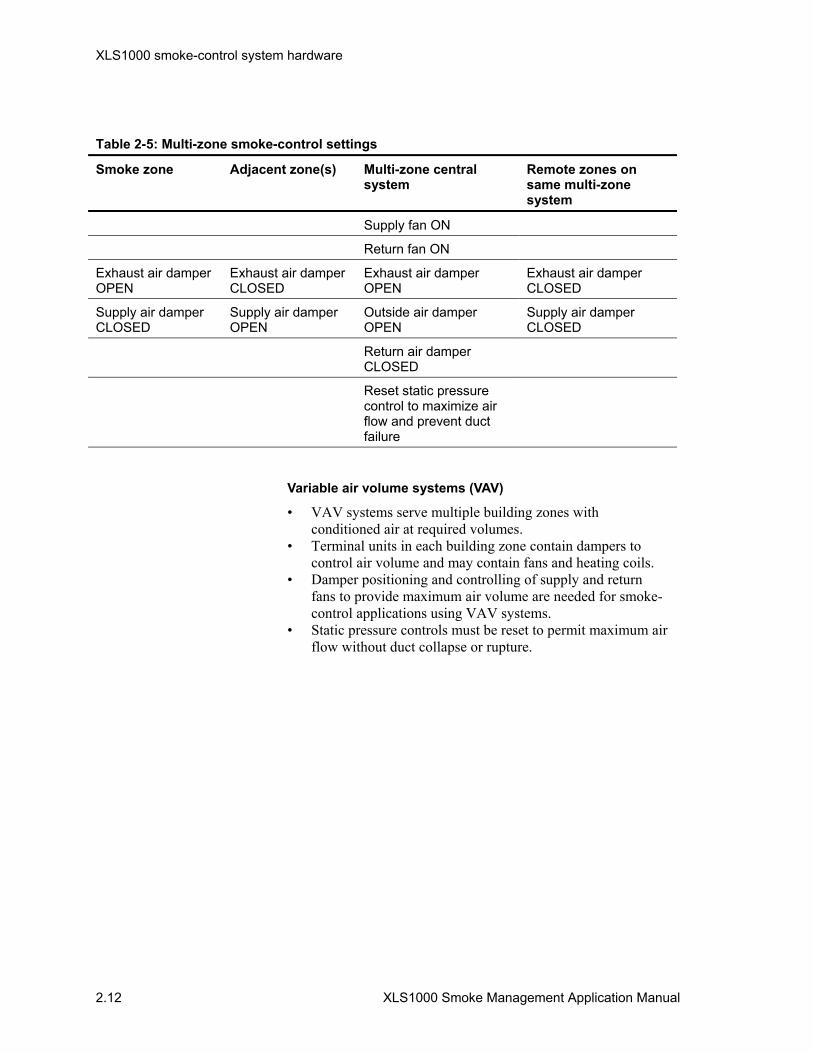
XLS1000 smoke-control system hardware
2.12 XLS1000 Smoke Management Application Manual
Table 2-5: Multi-zone smoke-control settings
Smoke zone Adjacent zone(s) Multi-zone central system
Remote zones on same multi-zone system
Supply fan ON
Return fan ON
Exhaust air damper OPEN
Exhaust air damper CLOSED
Exhaust air damper OPEN
Exhaust air damper CLOSED
Supply air damper CLOSED
Supply air damper OPEN
Outside air damper OPEN
Supply air damper CLOSED
Return air damper CLOSED
Reset static pressure control to maximize air flow and prevent duct failure
Variable air volume systems (VAV)
• VAV systems serve multiple building zones with conditioned air at required volumes.
• Terminal units in each building zone contain dampers to control air volume and may contain fans and heating coils.
• Damper positioning and controlling of supply and return fans to provide maximum air volume are needed for smoke-control applications using VAV systems.
• Static pressure controls must be reset to permit maximum air flow without duct collapse or rupture.
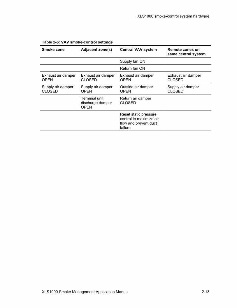
XLS1000 smoke-control system hardware
XLS1000 Smoke Management Application Manual 2.13
Table 2-6: VAV smoke-control settings
Smoke zone Adjacent zone(s) Central VAV system Remote zones on same central system
Supply fan ON
Return fan ON
Exhaust air damper OPEN
Exhaust air damper CLOSED
Exhaust air damper OPEN
Exhaust air damper CLOSED
Supply air damper CLOSED
Supply air damper OPEN
Outside air damper OPEN
Supply air damper CLOSED
Terminal unit discharge damper OPEN
Return air damper CLOSED
Reset static pressure control to maximize air flow and prevent duct failure

XLS1000 smoke-control system hardware
2.14 XLS1000 Smoke Management Application Manual
FSCS firefighter's smoke-control station (FSCS) The FSCS, where required, is most often located in the building's fire command center. The FSCS is a remotely networked panel, which also contains an FSCS series annunciator. Where the fire command center is also located in the building's central security center, an SCS with a graphic annunciator may also serve as the FCSC.
The FSCS series annunciator, with network support hardware, is capable of providing both monitoring and manual control of smoke-control system components. The FSCS series annunciator, when combined to the correct Signature Series modules, can be used by firefighters to start and stop fans and open and close dampers for smoke-control. The system, while designed primarily for occupant protection and egress, can be used by firefighters to exhaust smoke and allow for effective fire attack and extinguishment by manual means.
XLS1000 SCS installation XLS1000 SCS installation uses components detailed here and in greater detail in the XLS1000 Technical Reference Manual. System calculations, detailed hardware applications, and networking and wiring requirements for an SCS are as detailed in the XLS1000 Technical Reference Manual (P/N 95-7545).
Smoke-control systems, which are not interconnected as part of an XLS1000 fire alarm network panel, constitute a standalone system. The descriptions of components which follow address a standalone smoke-control system, but can also be applied to a FACP function with the smoke-control system components sharing common inputs and hardware in the XLS1000 fire alarm network panel.
Cabinets and enclosures XLS1000 smoke-control system components are mounted in any of the 3-CAB or RCC Series cabinets detailed in the XLS1000 Installation Manual. Each XLS1000 “CAB” series cabinet assembly is completed with inner and outer doors.
3-CHAS7
The 3-CHAS7 chassis provides the mounting, internal power and data distribution for up to seven plug-in local rail modules. Chassis design facilitates separation of power limited and nonpower-limited circuits by locating power-limited circuitry toward the front of the chassis and non-power limited wiring at the rear of the chassis. The 3-CHAS7 chassis mounts to the back wall of a 3-CAB7, 3-CAB14, and 3-CAB21 cabinets. Multiple 3-CHAS7 chassis are interconnected within a cabinet using the
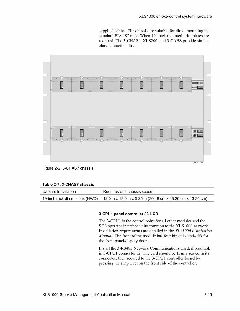
XLS1000 smoke-control system hardware
XLS1000 Smoke Management Application Manual 2.15
supplied cables. The chassis are suitable for direct mounting in a standard EIA 19” rack. When 19” rack mounted, trim plates are required. The 3-CHAS4, XLS200, and 3-CABS provide similar chassis functionality.
J8J9
J10J11
J8J9
J10J11
[3CHAS7.CDR] Figure 2-2: 3-CHAS7 chassis
Table 2-7: 3-CHAS7 chassis
Cabinet Installation Requires one chassis space
19-inch rack dimensions (HWD) 12.0 in x 19.0 in x 5.25 in (30.48 cm x 48.26 cm x 13.34 cm)
3-CPU1 panel controller / 3-LCD
The 3-CPU1 is the control point for all other modules and the SCS operator interface units common to the XLS1000 network. Installation requirements are detailed in the XLS1000 Installation Manual. The front of the module has four hinged stand-offs for the front panel/display door.
Install the 3-RS485 Network Communications Card, if required, in 3-CPU1 connector J2. The card should be firmly seated in its connector, then secured to the 3-CPU1 controller board by pressing the snap rivet on the front side of the controller.
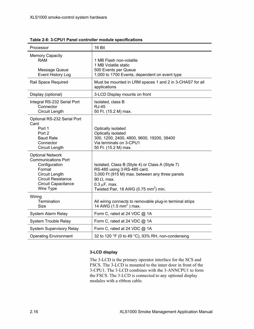
XLS1000 smoke-control system hardware
2.16 XLS1000 Smoke Management Application Manual
Table 2-8: 3-CPU1 Panel controller module specifications
Processor 16 Bit
Memory Capacity RAM Message Queue Event History Log
1 MB Flash non-volatile 1 MB Volatile static 500 Events per Queue 1,000 to 1700 Events, dependent on event type
Rail Space Required Must be mounted in LRM spaces 1 and 2 in 3-CHAS7 for all applications
Display (optional) 3-LCD Display mounts on front
Integral RS-232 Serial Port Connector Circuit Length
Isolated, class B RJ-45 50 Ft. (15.2 M) max.
Optional RS-232 Serial Port Card Port 1 Port 2 Baud Rate Connector Circuit Length
Optically isolated Optically isolated 300, 1200, 2400, 4800, 9600, 19200, 38400 Via terminals on 3-CPU1 50 Ft. (15.2 M) max.
Optional Network Communications Port Configuration Format Circuit Length Circuit Resistance Circuit Capacitance Wire Type
Isolated, Class B (Style 4) or Class A (Style 7) RS-485 using 3-RS-485 card. 3,000 Ft (915 M) max. between any three panels 90 Ω, max. 0.3 µF, max. Twisted Pair, 18 AWG (0.75 mm2) min.
Wiring Termination Size
All wiring connects to removable plug-in terminal strips 14 AWG (1.5 mm2 ) max.
System Alarm Relay Form C, rated at 24 VDC @ 1A
System Trouble Relay Form C, rated at 24 VDC @ 1A
System Supervisory Relay Form C, rated at 24 VDC @ 1A
Operating Environment 32 to 120 °F (0 to 49 °C), 93% RH, non-condensing
3-LCD display
The 3-LCD is the primary operator interface for the SCS and FSCS. The 3-LCD is mounted to the inner door in front of the 3-CPU1. The 3-LCD combines with the 3-ANNCPU1 to form the FSCS. The 3-LCD is connected to any optional display modules with a ribbon cable.

XLS1000 smoke-control system hardware
XLS1000 Smoke Management Application Manual 2.17
As the firefighter interface for the FSCS the 3-LCD switches and the LED indicators have the same functionality as the 3-CPU1/3-LCD. Only one 3-LCD is required for an entire network, at the point of network control, most often at the fire command center.
The display provides a 64 by 128 pixel back-lit liquid crystal display. Graphic symbols as well as text may be displayed on the screen.
1 2 3
654
7 8 9
0
Power Test
Reset
Alarm
ExpandedMessage
CommandMenu
Previous
Message
Next
Trouble MonitorSup'y
AlarmSilence
PanelSilence Drill
DisableGNDFault
CPUFail
[SMOKE34.CDR]
Figure 2-3: 3-LCD
LEDs on the 3-LCD display power, test, CPU fail, ground fault and disable functions. Switches with integral LED's are provided for reset, trouble silence, alarm silence, and drill functions.
Message queue select switches with integral LED's are provided for alarm, supervisory, trouble, and monitor message queues. Scrolling through a message queue is accomplished using Next and Previous message queue switches. Special function switches are also provided for expanded messages. The display is also equipped with a 10 digit numeric keypad with enter and delete keys.
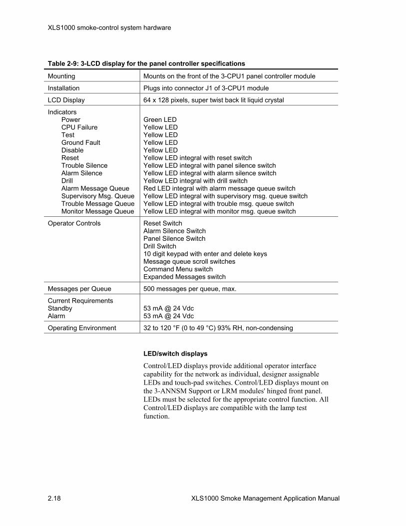
XLS1000 smoke-control system hardware
2.18 XLS1000 Smoke Management Application Manual
Table 2-9: 3-LCD display for the panel controller specifications
Mounting Mounts on the front of the 3-CPU1 panel controller module
Installation Plugs into connector J1 of 3-CPU1 module
LCD Display 64 x 128 pixels, super twist back lit liquid crystal
Indicators Power CPU Failure Test Ground Fault Disable Reset Trouble Silence Alarm Silence Drill Alarm Message Queue Supervisory Msg. Queue Trouble Message Queue Monitor Message Queue
Green LED Yellow LED Yellow LED Yellow LED Yellow LED Yellow LED integral with reset switch Yellow LED integral with panel silence switch Yellow LED integral with alarm silence switch Yellow LED integral with drill switch Red LED integral with alarm message queue switch Yellow LED integral with supervisory msg. queue switch Yellow LED integral with trouble msg. queue switch Yellow LED integral with monitor msg. queue switch
Operator Controls Reset Switch Alarm Silence Switch Panel Silence Switch Drill Switch 10 digit keypad with enter and delete keys Message queue scroll switches Command Menu switch Expanded Messages switch
Messages per Queue 500 messages per queue, max.
Current Requirements Standby Alarm
53 mA @ 24 Vdc 53 mA @ 24 Vdc
Operating Environment 32 to 120 °F (0 to 49 °C) 93% RH, non-condensing
LED/switch displays
Control/LED displays provide additional operator interface capability for the network as individual, designer assignable LEDs and touch-pad switches. Control/LED displays mount on the 3-ANNSM Support or LRM modules' hinged front panel. LEDs must be selected for the appropriate control function. All Control/LED displays are compatible with the lamp test function.

XLS1000 smoke-control system hardware
XLS1000 Smoke Management Application Manual 2.19
Table 2-10: Control / LED display specifications
Model LED Configuration Switch Configuration
3-24R 24 Red None
3-24Y 24 Yellow None
3-24G 24 Green None
3-12SG 12 Green 12
3-12SR 12 Red 12
3-12SY 12 Yellow 12
3-12/S1GY 12 Green over Yellow pairs 12
3-12/S1RY 12 Red over Yellow pairs 12
3-12/S2Y 24 Yellow 12
3-6/3S1G2Y 6 Green-over-Yellow-over-Yellow triads
6 triads
3-6/3S1GYR 6 Green-over-Yellow-over-Red triads
6 triads
Installation Mounts on the front of any LRM or 3-ANNSM module except the 3-CPU1 or 3-ANNCPU1

XLS1000 smoke-control system hardware
2.20 XLS1000 Smoke Management Application Manual
Installation
3-6/3S1Gxx3-12/Sxx3-24x 3-12Sx
SMO
KE25
.CD
R
Figure 2-4: LED labeling and displays
LED Display, model 3-24x LED, provides 24 LEDs. Adjacent to each LED is a slip-in label, for LED function identification. A typical application for smoke-control would be the confirming visual signals for damper position or fan operation using the 3-24G model.
Control/LED display, model 3-12/Sx, provides 12 LEDs, each grouped with one switch. Adjacent to each Control/LED is a slip-in label, for Control/LED function identification. A typical application for smoke-control would be the monitoring and control of dedicated fans in a stairtower which need only an ON/OFF operation.
Control/LED display, model 3-12/Sxx provides 24 LEDs, each pair of LEDs is grouped with one switch. Adjacent to each Control/LED group is a slip-in label, for Control/LED function identification. A typical application for smoke-control would be the monitoring and control of fans and dampers.
Control/LED display, model 3-6/3Sxxx provides 18 LEDs, each triad of LEDs is grouped with three software interlocked switches. Adjacent to each Control/LED group is a slip-in label, for Control/LED function identification. This Control/LED is well suited for HVAC fan control where ON/OFF/AUTO

XLS1000 smoke-control system hardware
XLS1000 Smoke Management Application Manual 2.21
controls are desired in place of EVSC3 series toggle switches on the FSCS.
LED/switch display and configuration
The switches on an LED/switch display may be configured to use one of three available operating modes. The available operating modes are:
• Toggle: The state of the switch changes each time the switch is pushed, i.e. “start” to “stop” or “stop” to “start.”
• The toggle switch mode can be used in smoke-control systems to perform two-state operations (on/off, open/close).
• The output of an “on” switch remains “on” during panel reset, and must be manually turned “off” when no longer required.
• Interlocked: Three adjacent toggle switches that operate as a group. Pushing any switch in the group turns the output of the other two switches “off” and turns its own output “on.”
• Interlocked switches are sometimes referred to as “radio buttons.
• The interlocked mode is commonly used for “Hand-Off-Auto” control of HVAC systems. It is also useful for controlling up to three mutually exclusive events, however, only one of the three events can be active at any one time.
• An interlocked switch in the “on” state can be turned “off” without activating a second switch by pressing the “on” switch a second time.
• The output of the “on” switch remains on, during panel reset, and must be manually turned “off” when no longer required.
• Momentary: The switch is “on” only while manually activated by the operator. The momentary switch mode is typically to issue momentary commands which typically are self-latching until complete. Common examples are: lamp tests, function reset and test sequences.
Switches are always configured in groups of three, regardless of the operating mode. Switches are configured using the LRM configuration function in the SDU program by selecting the Operator Layer tab.
3-LDSM LED display support rail module
The 3-LDSM LED display support module provides the circuitry required to operate a LED/Switch display when the cabinet does not have enough modules installed on a rail chassis to support the number of displays required. Connect the display ribbon

XLS1000 smoke-control system hardware
2.22 XLS1000 Smoke Management Application Manual
cable (P/N 250186) from connector J1 on the display to connector J1 on the module.
Mount the Control/LED Display in the recess on the front of the module door. Secure the display to the module with the four supplied plastic rivets. Snap the door into the module’s hinged stand-offs.
Table 2-11: 3-LDSM LED display support module specifications
Installation 1 LRM space
Operating Environment 32 to 120 °F (0 to 49 °C), 93% RH, non-condensing
[3LDSM.CDR]
TX RX
TX RX
J1
Figure 2-5: 3-LDSM Module

XLS1000 smoke-control system hardware
XLS1000 Smoke Management Application Manual 2.23
3-LRMF Blank Local Rail Module
The 3-LRMF Blank Module is used to fill unused module spaces on a rail. Install a 3-LRMF module in each rail space which does not have a module installed to: fill in any gaps in the rail, provide a uniform appearance, and prevent the entry of foreign objects into the cabinet.
3-RS485 Network RS-485 communications card
The 3-RS485 network data communications card is used to connect two 3-CPU1 Panel Controllers using copper conductors. A Class A/B circuit is provided for network communications, and a Class B circuit is provided for digital audio communications.
The 3-RS485 Network Communications Card is delivered installed with the 3-ANNCPU1 in the FSCS.
The card should be firmly seated in its connector, then secured to the 3-CPU1 controller board by pressing the snap rivets on the front side of the controller.
Table 2-12: 3-RS485 Network RS-485 communications card specifications
Installation Plugs into connector J2 of 3-CPU1 Panel Controller
Network Data Communications Circuit Circuit Configuration Data Rate Isolation Circuit Length Circuit Resistance Circuit Capacitance Wire Type
Class B (Style 4) or Class A (Style 7) 38.4 KB Isolated from “previous” 3-CPU1 5,000 Ft. (1,524 M) max between any three panels 90 Ω, max. 0.3 µF, max. Twisted Pair, 18 AWG (0.75 mm2) min.
Digitized Audio Communications Circuit Circuit Configuration Data Rate Isolation Circuit Length Circuit Resistance Circuit Capacitance Wire Type
Class B (Style 4) 327 KB Isolated from “previous” 3-CPU1 5,000 Ft. (1,524 M) Max between any three panels 90 Ω, max. 0.07 µF, max. Twisted Pair, 18 AWG (0.75 mm2), min.
Termination Removable plug-in terminal strips on 3-CPU1
Operating Environment 32 to 120 °F (0 to 49 °C), 93% RH, non-condensing
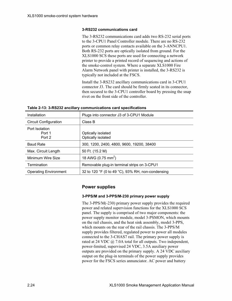
XLS1000 smoke-control system hardware
2.24 XLS1000 Smoke Management Application Manual
3-RS232 communications card
The 3-RS232 communications card adds two RS-232 serial ports to the 3-CPU1 Panel Controller module. There are no RS-232 ports or common relay contacts available on the 3-ANNCPU1. Both RS-232 ports are optically isolated from ground. For the XLS1000 SCS these ports are used for connecting a network printer to provide a printed record of sequencing and actions of the smoke-control system. Where a separate XLS1000 Fire Alarm Network panel with printer is installed, the 3-RS232 is typically not included at the FSCS.
Install the 3-RS232 ancillary communications card in 3-CPU1 connector J3. The card should be firmly seated in its connector, then secured to the 3-CPU1 controller board by pressing the snap rivet on the front side of the controller.
Table 2-13: 3-RS232 ancillary communications card specifications
Installation Plugs into connector J3 of 3-CPU1 Module
Circuit Configuration Class B
Port Isolation Port 1 Port 2
Optically isolated Optically isolated
Baud Rate 300, 1200, 2400, 4800, 9600, 19200, 38400
Max. Circuit Length 50 Ft. (15.2 M)
Minimum Wire Size 18 AWG (0.75 mm2)
Termination Removable plug-in terminal strips on 3-CPU1
Operating Environment 32 to 120 °F (0 to 49 °C), 93% RH, non-condensing
Power supplies
3-PPS/M and 3-PPS/M-230 primary power supply
The 3-PPS/M(-230) primary power supply provides the required power and related supervision functions for the XLS1000 SCS panel. The supply is comprised of two major components: the power supply monitor module, model 3-PSMON, which mounts on the rail chassis, and the heat sink assembly, model 3-PPS, which mounts on the rear of the rail chassis. The 3-PPS/M supply provides filtered, regulated power to power all modules connected to the 3-CHAS7 rail. The primary power supply is rated at 24 VDC @ 7.0A total for all outputs. Two independent, power-limited, supervised 24 VDC, 3.5A auxiliary power outputs are provided on the primary supply. A 24 VDC auxiliary output on the plug-in terminals of the power supply provides power for the FSCS series annunciator. AC power and battery

XLS1000 smoke-control system hardware
XLS1000 Smoke Management Application Manual 2.25
connections are made to fixed terminals on the heat sink assembly, remote from the panel’s power limited wiring.
The primary power supply supervises the standby batteries and provides a dual-rate constant current battery charger featuring automatic temperature compensation. The charger is capable of charging batteries up to 60 AH. A remote battery temperature sensor is available when a remote battery cabinet is used. Knowing the battery temperature enables the charging circuitry to maximize charging efficiently, without damaging the battery due to overheating. A battery monitor circuit disconnects the batteries from the system when battery voltage drops below acceptable limits, preventing possible memory problems and a total discharge of the batteries.
The power supply checks the AC input source and initiates the automatic transfer to batteries in event of a brownout or loss of AC power. In the event of a failure of one or more booster power supplies, the primary power supply determines its ability, along with the surviving booster supplies, to supply the load. Should the load ever exceed the ability of the primary and surviving booster supplies to meet the demand, the standby batteries are automatically switched in. The supply will also transfer to battery should an overload cause its heat sink temperature reach a high level.
Battery failure is annunciated if the battery fails to maintain an acceptable voltage level. Load testing continues periodically, until the battery capacity is sufficient to meet the load test criteria.
The 3-PSMON Primary Power Supply Monitor local rail module provides the interface between the power supply and the XLS1000 SCS panel, making the required data and power connections to and from the rail chassis. The monitor module occupies slot #3 (only), next to the 3-CPU1 on the rail and is secured to the assembly using snap rivet fasteners. The module also features a hinged front panel for mounting a display or a blank protective faceplate.
The model 3-PPS/M Power Supply requires 120 VAC, 50/60 Hz. input voltage. The model 3-PPS/M-230 Power Supply requires 230 VAC, 50/60 Hz input voltage.
Table 2-14: 3-PPS/M (-230) primary power supply specifications
Installation LRM slot #3 only, adjacent to the 3-CPU1; heat sink assembly mounts behind rails
Power Input 3-PPS/M 3-PPS/M-230
120 VAC, 3.0 A, 50-60 Hz 230 VAC, 1.5 A, 50-60 Hz.
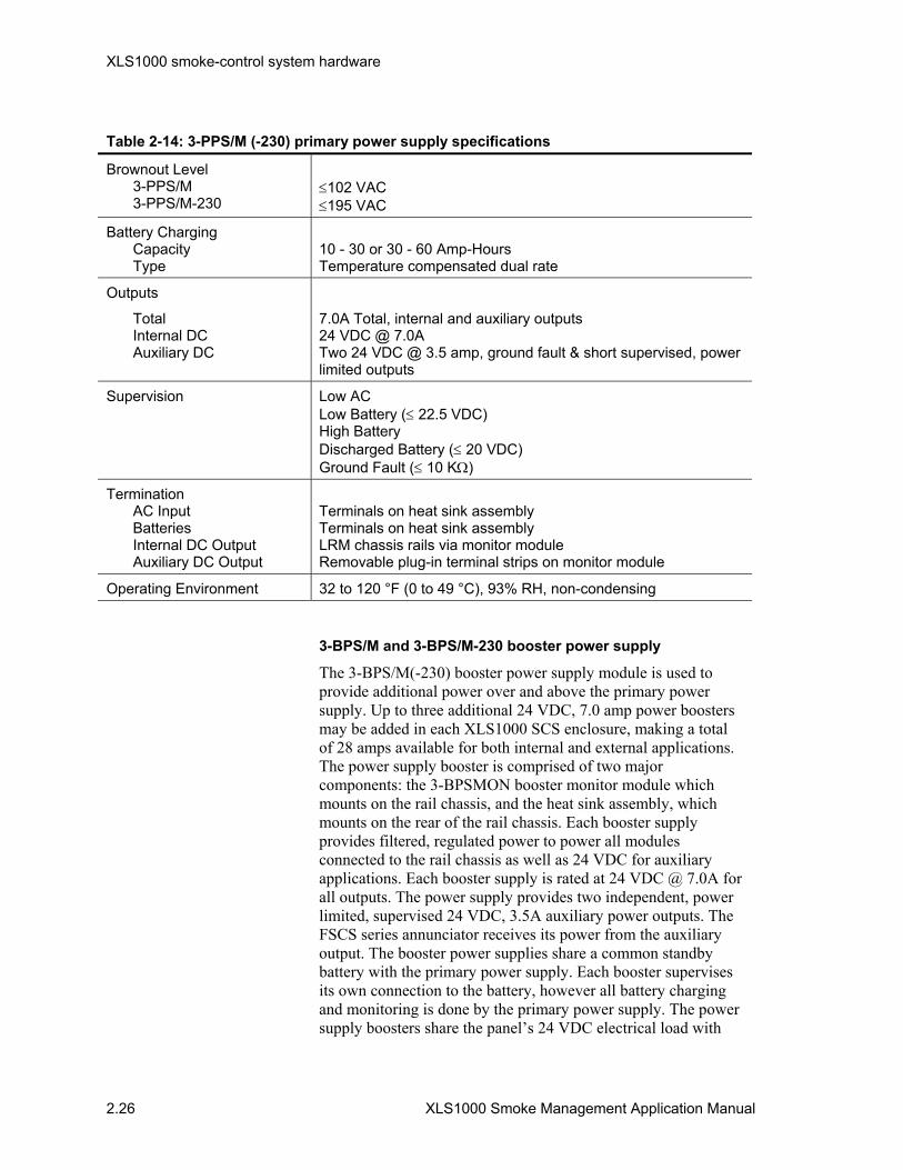
XLS1000 smoke-control system hardware
2.26 XLS1000 Smoke Management Application Manual
Table 2-14: 3-PPS/M (-230) primary power supply specifications
Brownout Level 3-PPS/M 3-PPS/M-230
≤102 VAC ≤195 VAC
Battery Charging Capacity Type
10 - 30 or 30 - 60 Amp-Hours Temperature compensated dual rate
Outputs
Total Internal DC Auxiliary DC
7.0A Total, internal and auxiliary outputs 24 VDC @ 7.0A Two 24 VDC @ 3.5 amp, ground fault & short supervised, power limited outputs
Supervision Low AC Low Battery (≤ 22.5 VDC) High Battery Discharged Battery (≤ 20 VDC) Ground Fault (≤ 10 KΩ)
Termination AC Input Batteries Internal DC Output Auxiliary DC Output
Terminals on heat sink assembly Terminals on heat sink assembly LRM chassis rails via monitor module Removable plug-in terminal strips on monitor module
Operating Environment 32 to 120 °F (0 to 49 °C), 93% RH, non-condensing
3-BPS/M and 3-BPS/M-230 booster power supply
The 3-BPS/M(-230) booster power supply module is used to provide additional power over and above the primary power supply. Up to three additional 24 VDC, 7.0 amp power boosters may be added in each XLS1000 SCS enclosure, making a total of 28 amps available for both internal and external applications. The power supply booster is comprised of two major components: the 3-BPSMON booster monitor module which mounts on the rail chassis, and the heat sink assembly, which mounts on the rear of the rail chassis. Each booster supply provides filtered, regulated power to power all modules connected to the rail chassis as well as 24 VDC for auxiliary applications. Each booster supply is rated at 24 VDC @ 7.0A for all outputs. The power supply provides two independent, power limited, supervised 24 VDC, 3.5A auxiliary power outputs. The FSCS series annunciator receives its power from the auxiliary output. The booster power supplies share a common standby battery with the primary power supply. Each booster supervises its own connection to the battery, however all battery charging and monitoring is done by the primary power supply. The power supply boosters share the panel’s 24 VDC electrical load with
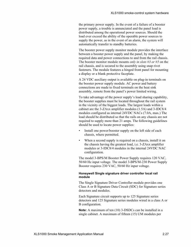
XLS1000 smoke-control system hardware
XLS1000 Smoke Management Application Manual 2.27
the primary power supply. In the event of a failure of a booster power supply, a trouble is annunciated and the panel load is distributed among the operational power sources. Should the load ever exceed the ability of the operable power sources to supply the power, as in the event of an alarm, the system will automatically transfer to standby batteries.
The booster power supply monitor module provides the interface between a booster power supply and the panel, by making the required data and power connections to and from the rail chassis. The booster monitor module mounts only in slots #3 or #5 on the rail chassis, and is secured to the assembly using snap rivet fasteners. The module features a hinged front panel for mounting a display or a blank protective faceplate.
A 24 VDC auxiliary output is available on plug-in terminals on the booster power supply module. AC power and battery connections are made to fixed terminals on the heat sink assembly, remote from the panel’s power limited wiring.
To take advantage of the power supply’s load sharing capability, the booster supplies must be located throughout the rail system in the vicinity of the biggest loads. The largest loads within a cabinet are the 3-ZAxx amplifier modules (1.5A) and 3-IDC8/4 modules configured as internal 24VDC NACs (7.0A, max.) The load should be distributed so that the rails on any chassis are not required to supply more than 21 amps. The following guidelines should be used to locate power supplies:
• Install one power/booster supply on the left side of each chassis, where permitted.
• When a second supply is required on a chassis, install it on the chassis having the greatest load, i.e. 3-ZAxx amplifier modules or 3-IDC8/4 modules in the internal 24VDC NAC configuration.
The model 3-BPS/M Booster Power Supply requires 120 VAC, 50/60 Hz input voltage. The model 3-BPS/M-230 Power Supply Booster requires 230 VAC, 50/60 Hz input voltage.
Honeywell Single signature driver controller local rail module
The Single Signature Driver Controller module provides one Class A or B Signature Data Circuit (SDC) for Signature series detectors and modules.
Each Signature circuit supports up to 125 Signature series detectors and 125 Signature series modules wired in a class A or B configuration.
Note: A maximum of ten (10) 3-DSDCs can be installed in a single cabinet. A maximum of fifteen (15) UM modules per
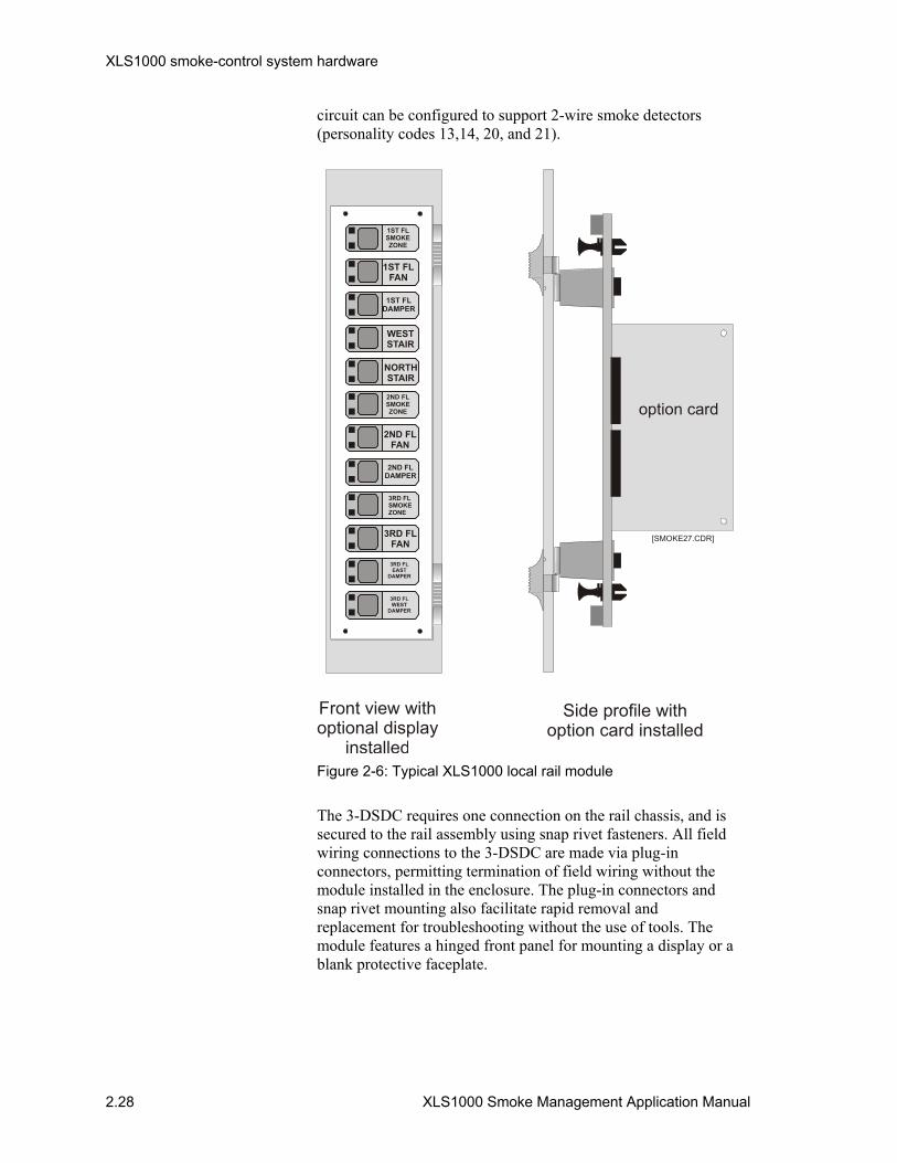
XLS1000 smoke-control system hardware
2.28 XLS1000 Smoke Management Application Manual
circuit can be configured to support 2-wire smoke detectors (personality codes 13,14, 20, and 21).
Front view withoptional display
installed
Side profile withoption card installed
[SMOKE27.CDR]
1ST FLSMOKE ZONE
1ST FLFAN
1ST FLDAMPER
WEST STAIR
NORTHSTAIR
2ND FLSMOKEZONE
2ND FLFAN
2ND FLDAMPER
3RD FLSMOKEZONE
3RD FLFAN
3RD FL EAST
DAMPER
option card
3RD FL WEST
DAMPER
Figure 2-6: Typical XLS1000 local rail module
The 3-DSDC requires one connection on the rail chassis, and is secured to the rail assembly using snap rivet fasteners. All field wiring connections to the 3-DSDC are made via plug-in connectors, permitting termination of field wiring without the module installed in the enclosure. The plug-in connectors and snap rivet mounting also facilitate rapid removal and replacement for troubleshooting without the use of tools. The module features a hinged front panel for mounting a display or a blank protective faceplate.
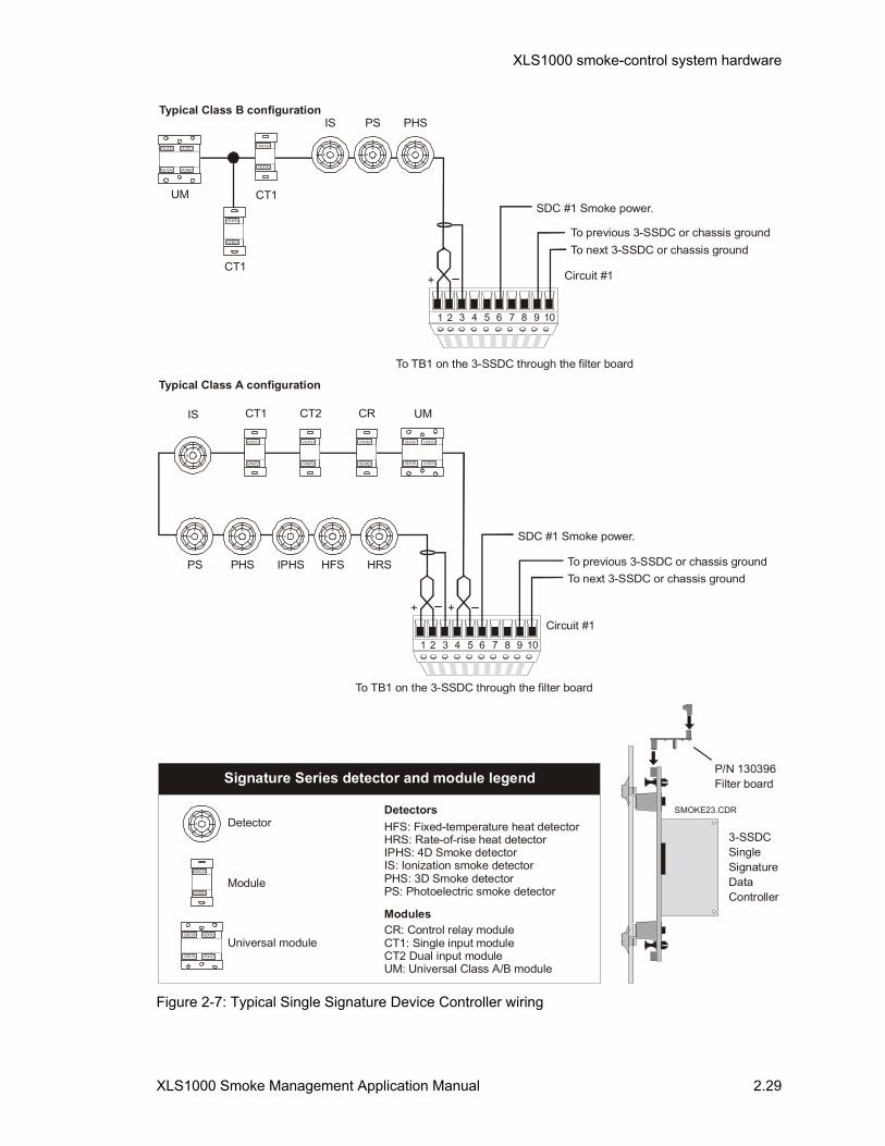
XLS1000 smoke-control system hardware
XLS1000 Smoke Management Application Manual 2.29
Circuit #1
To TB1 on the 3-SSDC through the filter board
To TB1 on the 3-SSDC through the filter board
1 2 43 5 6 7 8 9 10
++
SDC #1 Smoke power.
To previous 3-SSDC or chassis groundTo next 3-SSDC or chassis ground
Typical Class A configuration
Typical Class B configuration
IS
PS PHS
CT1
IPHS
CT2
HFS
CR
HRS
UM
3-SSDCSingleSignatureDataController
P/N 130396Filter board
SMOKE23.CDR
To previous 3-SSDC or chassis groundTo next 3-SSDC or chassis ground
IS PS PHS
CT1
CT1
UM
1 2 43 5 6 7 8 9 10
+ Circuit #1
SDC #1 Smoke power.
DetectorDetectors
Modules
Module
Universal module
Signature Series detector and module legend
HFS: Fixed-temperature heat detectorHRS: Rate-of-rise heat detector
IS: Ionization smoke detectorIPHS: 4D Smoke detector
PHS: 3D Smoke detectorPS: Photoelectric smoke detector
CR: Control relay moduleCT1: Single input moduleCT2 Dual input moduleUM: Universal Class A/B module
Figure 2-7: Typical Single Signature Device Controller wiring

XLS1000 smoke-control system hardware
2.30 XLS1000 Smoke Management Application Manual
Table 2-15: Single signature driver controller local rail module specifications
Installation 1 LRM space
Module Configuration 1 Signature Data Circuit
Circuit Configuration Class B (Style 4) or Class A (Style 6)
Circuit Capacity 125 Signature series detectors and 125 Signature series modules1 per circuit. Maximum of 124 “T-Taps.” 1A maximum of 15 UM modules per circuit can be configured to support 2-Wire smoke detectors (personality codes 13,14, 20, & 21).
Smoke Power 24 VDC @ 100 mA
Circuit Resistance 79 Ω, max. (capacitance dependent)
Circuit Capacitance 0.5 µF, max.
Max. Circuit Resistance Between Isolators
6 Ω
Maximum Wire Size 14 AWG (1.5 mm2)
Termination Removable plug-in terminal strips
Operating Environment 32 to 120 °F (0 to 49 °C), 93% RH, non-condensing
Ground Fault 10 kΩ
3-IDC8/4 traditional zone I/O local rail module
The traditional zone module provides eight Class B (Style B) direct connect Initiating Device Circuits (IDCs) for compatible 2-wire smoke detectors and dry contact initiating devices. Four of the eight IDCs may be converted to Class B (Style Y) Notification Appliance Circuits (NAC).
Each IDC may be set for latching/non-latching operation and verified/non-verified operation, and each IDC can support up to 30 model 6270B photoelectric smoke detectors or 50 model 6250B ionization detectors.
Note: When the rail chassis is used as the 24 VDC source, the module is limited to a 7 amp total current draw. Input terminals are provided to supply the external source, which must be power limited.
The traditional zone module requires one connection on the rail chassis, and is secured to the assembly using snap rivet fasteners. All field wiring connections to the traditional zone module are made via plug-in connectors, permitting termination of field wiring without the module installed in the enclosure. The plug-in connectors and snap rivet mounting also facilitate rapid removal and replacement for trouble shooting without the use of tools.
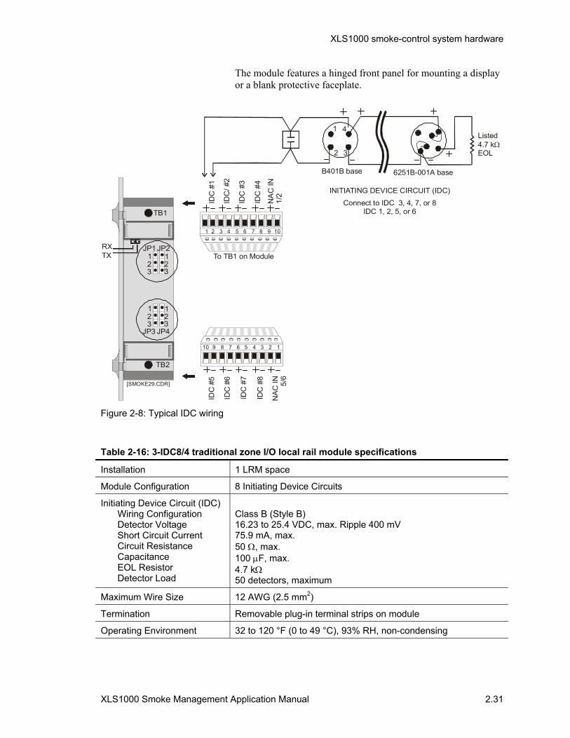
XLS1000 smoke-control system hardware
XLS1000 Smoke Management Application Manual 2.31
The module features a hinged front panel for mounting a display or a blank protective faceplate.
Listed4.7 kEOL
Ω
B401B base
Connect to IDC 3, 4, 7, or 8IDC 1, 2, 5, or 6
6251B-001A base
1 4
2 3
INITIATING DEVICE CIRCUIT (IDC)
IDC
/ #2
IDC
#1
IDC
#3
IDC
#4
NA
C IN
1/2
To TB1 on Module
1 2 43 5 6 7 8 9 10
IDC
#5
IDC
#6
IDC
#7
IDC
#8
NA
C IN 5/
6
124 35678910
TXJP1
JP3
1
1
1
1
2
2
2
2
3
3
3
3
JP2
JP4
RX
TB1
TB2
[SMOKE29.CDR]
Figure 2-8: Typical IDC wiring
Table 2-16: 3-IDC8/4 traditional zone I/O local rail module specifications
Installation 1 LRM space
Module Configuration 8 Initiating Device Circuits
Initiating Device Circuit (IDC) Wiring Configuration Detector Voltage Short Circuit Current Circuit Resistance Capacitance EOL Resistor Detector Load
Class B (Style B) 16.23 to 25.4 VDC, max. Ripple 400 mV 75.9 mA, max. 50 Ω, max. 100 µF, max. 4.7 kΩ 50 detectors, maximum
Maximum Wire Size 12 AWG (2.5 mm2)
Termination Removable plug-in terminal strips on module
Operating Environment 32 to 120 °F (0 to 49 °C), 93% RH, non-condensing

XLS1000 smoke-control system hardware
2.32 XLS1000 Smoke Management Application Manual
Components
Detectors
Signature series detectors
The selection and installation of smoke detection is based upon the geometry of the protected space and the type of expected fire. Signature Series smoke detector application and spacing is detailed in the Signature Series Intelligent Smoke and Heat Detectors Applications Bulletin (P/N 270145). Installation instructions and specifications for Signature series (SIGA) detectors is contained in the Signature Series Component Installation Manual (270682).
Beam detection
High ceilings and large open spaces in buildings are suitable for beam smoke detector units where spacing up to 330 ft (100.5m) between units is desired or needed. The Model 6424 Beam Smoke Detector can be used for these special applications. Consult the Catalog Number 6424 data sheet for specification and installation information.
Manual Fire Alarm Pull Stations
Manual fire alarm pull stations are normally used for occupant notification in buildings and are not to enable a smoke-control system. Manual operation of a dedicated smoke-control system, such as a stairwell pressurization system, may be specified by the building system designer or placed in controlled locations accessible to authorized personnel only. For such applications, the Signature series single or 2-Stage Fire Alarm Stations contained in the Signature Series Component Installation Manual are appropriate.
Modules Signature series modules use personality codes to configure a module's operation and provide application flexibility. Single channel Signature modules are programmed with one personality code. Dual channel Signature modules are programmed with two personality codes. Personality codes are listed on the installation sheet for each Signature module. Use of Signature modules will require the use of the 3-DSDC, which downloads the personality codes which determines how the module will operate.
SIGA-CT1
The CT1 is an analog addressable device used to connect a Class B normally-open Alarm, Supervisory, or Monitor type dry
XLS1000 smoke-control system hardware
XLS1000 Smoke Management Application Manual 2.33
contact initiating device circuit (IDC) to a Signature Loop Controller. One device address is required.
Personality code 1, N/O alarm latching (Class B): The CT1 is factory assigned personality code 1. Personality code 1 configures the CT1 for Class B normally-open dry contact initiating devices. When the N/O input contact of an initiating device is closed, an alarm signal is sent to the loop controller and the alarm condition is latched at the module. Personality code 2, N/O alarm delayed latching (Class B): Personality code 2 operates the same as personality code 1 except that contact closure must be maintained for approximately 16 seconds before an Alarm status is generated. Personality code 2 is only for use with non-retarded waterflow alarm switches.
Personality code 3, N/O active-non-latching (Class B): A contact closure causes an active instead of an alarm status and does NOT latch at the module. Personality code 3 is typically used for monitoring fans, dampers, or doors.
Personality code 4, N/O active latching (Class B): A contact closure causes an active instead of an alarm status, which is latched at the module. Personality codes 4 is typically used for monitoring supervisory and tamper switches.
SIGA-CT2
The Dual Input Module, Model CT2, is a component of the Signature Series System. The CT2 is an analog addressable device used to connect up to two Class B normally-open Alarm, Supervisory, or Monitor type dry contact IDCs to a Signature Loop Controller. Two (2) device addresses are required.
Personality code 1, N/O alarm latching (Class B): The CT2 is factory assigned personality code 1 to input channels 1 and 2. Personality code 1 configures the CT2 for Class B normally-open dry contact initiating devices. When the N/O input contact of an initiating device is closed, an alarm signal is sent to the loop controller and the alarm condition is latched at the module.
Personality code 2, N/O alarm delayed latching (Class B): Personality code 2 operates the same as personality code 1 except that contact closure must be maintained for approximately 16 seconds before an Alarm status is generated. Personality code 2 is only for use with non-retarded waterflow alarm switches.
Personality code 3, N/O active-non-latching (Class B): A contact closure causes an active instead of an alarm status and does not latch at the module. Personality code 3 is typically used for monitoring fans, dampers, and doors.
Personality code 4, N/O active latching (Class B): A contact closure causes an active instead of an alarm status, which is

XLS1000 smoke-control system hardware
2.34 XLS1000 Smoke Management Application Manual
latched at the module. Personality codes 4 is typically used for monitoring supervisory and tamper switches.
SIGA-CR
The Control Relay Module, Model CR, is a component of the Signature Series System. The CR is an addressable device used to provide one Form “C” dry relay contact to control external appliances such as door closers, fans, dampers, or equipment shutdown. The system firmware ensures that the relay is in the proper ON/OFF state. Upon command from the loop controller, the CR relay energizes. Terminals 6 and 7 provide a normally-closed relay connection; terminals 7 and 8 provide a normally-open relay connection. One (1) device address is required. The loop controller assigns an address to the CR automatically or a custom address can be assigned to the module via laptop computer; no addressing switches are used.
Personality code 8, Dry contact output: The CR is factory assigned personality code 8 which configures the CR as an output dry relay contact.
SIGA-MM1
The Monitor Module, Model MM1, is a component of the Signature Series System. The MM1 is an analog addressable device used to connect a Class B normally-open monitor type dry contact Initiating Device Circuit (IDC) to a Signature Loop Controller. One (1) device address is required.
Personality code 3, N/O active-non-latching (Class B): The MM1 is factory assigned personality code 3. This configures the MM1 for monitoring of fans, dampers, doors, etc. A contact closure generates an active status. The active status does NOT latch at the module (it follows the status of the input switch).
SIGA-WTM
The Waterflow/Tamper Module, Model WTM, is a component of the Signature Series System. The WTM is an analog addressable device used to connect Class B normally-open Waterflow Alarm and Supervisory IDCs to a Signature Loop Controller. Two (2) device addresses are required. Personality code 2, N/O alarm delayed latching (Class B): Personality code 2 is factory assigned to input channel 1 of the WTM. This configures channel 1 for use with non-retarded waterflow alarm switches. When the N/O input contact of an initiating device is closed and maintained closed for approximately 16 seconds, an alarm status is generated and latched at the module.
Personality code 4, N/O active latching (Class B): Personality code 4 is factory assigned to input channel 2 of the WTM. This

XLS1000 smoke-control system hardware
XLS1000 Smoke Management Application Manual 2.35
configures channel 2 for use with supervisory and tamper switches. Contact closure generates an active status which is latched at the module.
SIGA-IM
The Isolator Module, Model IM is a component of the Signature Series System. The IM is an analog addressable device used to protect a Class A data line from total collapse due to wire to wire short circuits. The IM monitors line voltage and opens the data line when a short is detected. A short will be isolated between two IMs located electrically closest to the short. One (1) detector address is required for each IM.
SIGA-UM
The universal Class A/B module, model UM is a component of the Signature Series System. The UM is an analog addressable device used to connect any one of the following:
• Dual input Class B IDC • Class A or B IDC • Class A or B for 2-wire smoke detectors IDCs on one circuit • Form “C” dry contact relay
The actual function performed by the UM is determined by the personality code downloaded to the module from the Signature Loop Controller during system configuration.
Personality code 1, N/O alarm latching (Class B): Personality code 1 configures input 1 and/or 2 of the UM for Class B normally-open dry contact initiating devices. When the N/O input contact of an initiating device is closed, an alarm signal is sent to the loop controller and the alarm condition is latched at the module. Personality code 2, N/O alarm delayed latching (Class B): Personality code 2 operates the same as personality code 1 except that contact closure must be maintained for approximately 16 seconds before an Alarm status is generated. Personality code 2 is only for use with non-retarded waterflow alarm switches.
Personality code 3, N/O active-non-latching (Class B): A contact closure causes an active instead of an alarm status and does not latch at the module. Personality code 3 is typically used for monitoring fans, dampers, or doors.
Personality code 4, N/O active latching (Class B): A contact closure causes an active instead of an alarm status, which is latched at the module. Personality code 4 is typically used for monitoring supervisory and tamper switches.
Personality code 8, dry contact output: Personality code 8 configures the UM as a Form “C” dry relay contact to control

XLS1000 smoke-control system hardware
2.36 XLS1000 Smoke Management Application Manual
external appliances including door closers, fans, dampers or equipment shutdown.
Personality code 9, N/O alarm latching (Class A): Personality code 9 configures the UM for connection of Class A normally-open dry contact initiating devices including pull-stations. When the N/O input contact of an initiating device is closed, an alarm signal is sent to the loop controller and the alarm condition is latched at the module. Personality code 10, N/O alarm delayed latching (Class A): Personality code 10 operates the same as personality code 9 except that contact closure must be maintained for approximately 16 seconds before an alarm status is generated. Personality code 10 is typically used with waterflow alarm switches. Personality code 11, N/O active non-latching (Class A): Personality code 11 operates the same as personality code 9 except that contact closure causes an active instead of an alarm status and does not latch at the module. Personality code 11 is typically used for monitoring fans dampers, and doors. Personality code 12, N/O active latching (Class A): Personality code 12 operates the same as personality code 9 except that contact closure causes an active instead of an alarm status, which is latched at the module. Personality code 12 is typically used for monitoring supervisory and tamper switches. Personality code 13, 2 Wire smoke-non-verified (Class B): Personality code 13 configures the UM for monitoring of 2-wire conventional smoke detectors and normally-open contact initiating devices such as pull stations, on the same circuit. Personality code 14, 2-Wire smoke-verified (Class B): Personality code 14 configures the UM for monitoring of 2 wire conventional smoke devices. Normally-open contact initiating devices may not be mixed with 2-wire conventional smoke detectors.
Personality code 15, Signal output (Class A): Personality code 15 configures the UM for connection of a Class A output NAC. Personality code 16, Signal output module (Class B): Personality code 16 configures the UM for connection of a Class B output NAC. Personality code 20, 2-Wire smoke-Non-verified (Class A): Personality code 20 operates the same as personality code 13, except that wiring is Class A. Personality code 21, 2-Wire smoke-verified (Class A): Personality code 21 operates the same as personality code 14, except that wiring is Class A.

XLS1000 smoke-control system hardware
XLS1000 Smoke Management Application Manual 2.37
SIGA-MP1/ SIGA-MP2/ SIGA-MP2L
The MP1, MP2, and MP2L are mounting plates which allow for the installation of multiple Signature plug-in modules in series. The MP1 and MP2 mount in Honeywell standard equipment enclosures.
4321
4321
1 2 3 4
1 2 3 4
1 2 3 4
1 2 3 4
P1 P2
TB1 TB2
TB7
TB8 TB9
TB15
UIO6
UIO2R
UIO6R[SMOKE210.CDR]
TB7
4321
1 2 3 4
1 2 3 4
1 2 3 4
1 2 3 4
P1 P2
TB1
TB8JP1A JP2A JP3A JP4A JP5A
JP1B JP2B JP3B JP4B JP5B
TB9 TB10 TB11 TB12 TB13
TB2
1 2 3 4
1 2 3 4
1 2 3 4
1 2 3 4
P3 P4
TB3 TB4
1 2 3 4
1 2 3 4
1 2 3 4
1 2 3 4
P5 P6
TB5 TB6
TB15
4321
4321
4321
1 2 3 4
1 2 3 4
1 2 3 4
1 2 3 4
P1 P2
TB1 TB2
1 2 3 4
1 2 3 4
1 2 3 4
1 2 3 4
P3 P4
TB3 TB4
1 2 3 4
1 2 3 4
1 2 3 4
1 2 3 4
P5 P6
TB5 TB6
4321
TB7
TB14
TB15
Figure 2-9: Signature series universal input/output motherboards
SIGA-UIO2R/ SIGA-UIO6(R)
The UIO2R, UIO6, and UIO6R universal input/output motherboards provide mounting and wiring terminations for 2 to 6 M series modules. The motherboard conveniently mounts into

XLS1000 smoke-control system hardware
2.38 XLS1000 Smoke Management Application Manual
equipment enclosures or racks. Modules plug into the motherboard and captive screws fasten them down. All module field wiring goes to terminal blocks on the motherboard to permit rapid removal and replacement for troubleshooting.
SIGA-MCR
The MCR control relay module is an addressable Signature Series component. A Form C dry contract relay in the MCR may control equipment shutdown or external appliances like door closers, fans, and dampers.
Personality code 8, dry contact output: Personality code 8 , which is factory assigned, configures the MCR as an output dry contact relay to control external appliances including door closers, fans, dampers or equipment shutdown.
SIGA-MCT2
The MCT2 Dual input module is an addressable Signature Series component used to connect up to two Class B normally-open dry contact IDCs to a Signature controller.
Personality code 1, N/O alarm latching (Class B): Personality code 1 configures input 1 and/or 2 of the UM for Class B normally-open dry contact initiating devices including pull stations. Personality code 2, N/O alarm delayed latching (Class B): Personality code 2 operates the same as personality code 1 except that contact closure must be maintained for approximately 16 seconds before an Alarm status is generated. Personality code 2 is only for use with non-retarded waterflow alarm switches.
Personality code 3, N/O active-non-latching (Class B): A contact closure causes an active instead of an alarm status and does not latch at the module. Personality code 3 is typically used for monitoring fans, dampers, or doors.
Personality code 4, N/O active latching (Class B): A contact closure causes an active instead of an alarm status, which is latched at the module. Personality code 4 is best used for monitoring supervisory and tamper switches.
SIGA-MAB
The MAB Class A/B input/output module, is an addressable Signature Series Component which may be used as:
• Class A or B dry contact IDC • Class A or B NAC
Data entry may define this module as a UM. Make certain the personality code for channel 2 remains 00.
XLS1000 smoke-control system hardware
XLS1000 Smoke Management Application Manual 2.39
Personality code 1, N/O alarm latching (Class B): Personality code 1 configures input 1 and/or 2 of the MAB for Class B normally-open dry contact initiating devices. Personality code 2, N/O alarm delayed latching (Class B): Personality code 2 operates the same as personality code 1 except that contact closure must be maintained for approximately 16 seconds before an Alarm status is generated. Personality code 2 is only for use with non-retarded waterflow alarm switches.
Personality code 3, N/O active-non-latching (Class B): A contact closure causes an active instead of an alarm status and does not latch at the module. Personality code 3 is typically used for monitoring fans, dampers, or doors.
Personality code 4, N/O active latching (Class B): Personality code 4 is typically used for monitoring supervisory and tamper switches.
Personality code 9, N/O alarm latching (Class A): Personality code 9 configures the MAB for connection of Class A normally-open dry contact initiating devices including pull-stations. Personality code 10, N/O alarm delayed latching (Class A): Personality code 10 operates the same as personality code 9 except that contact closure must be maintained for approximately 16 seconds before an alarm status is generated. Personality code 10 is typically used with waterflow alarm switches. Personality code 11, N/O active non-latching (Class A): Personality code 11 operates the same as personality code 9 except that contact closure causes an active instead of an alarm status and does not latch at the module. Personality code 11 is typically used for monitoring fans dampers, and doors. Personality code 12, N/O active latching (Class A): Personality code 12 operates the same as personality code 9 except that contact closure causes an active instead of an alarm status, which is latched at the module. Personality code 12 is best used for monitoring supervisory and tamper switches.
Personality code 15, Signal Output (Class A): Personality code 15 configures the MAB for connection of a Class A output NAC. Personality code 16, Signal output module (Class B): Personality code 16 configures the MAB for connection of a Class B output NAC.
ARM-8
The ARM-8 Auxiliary Relay Module provides a mounting rail and protective cover for up to eight ARA-1 high current relays. It comes equipped with one ARA-1. Typical applications include: motor control, amplifier switchover, and electric door release.

XLS1000 smoke-control system hardware
2.40 XLS1000 Smoke Management Application Manual
The ARA-1 is a Form C (DPDT), general purpose, plug-in relay. The ARA-1 mounting base provides screw terminals to connect field wiring easily. A diode is included across the relay energizing coil input terminals to protect it against transients and EMF.
When the ARA-1 is energized, the normally-closed contacts will open (break) before the normally-open contacts will close (make).
AUXILIARY RELAY MODULEMODEL ARM8
C
POTTER & BRUMFIELDK10P-11D15-2424VDC
C
POTTER & BRUMFIELDK10P-11D15-2424VDC
C
POTTER & BRUMFIELDK10P-11D15-2424VDC
C
POTTER & BRUMFIELDK10P-11D15-2424VDC
C
POTTER & BRUMFIELDK10P-11D15-2424VDC
C
POTTER & BRUMFIELDK10P-11D15-2424VDC
C
POTTER & BRUMFIELDK10P-11D15-2424VDC
C
POTTER & BRUMFIELDK10P-11D15-2424VDC
ARA-
1SM
K.C
DR
Figure 2-10: ARM-8 module
XLS1000 smoke-control system hardware
XLS1000 Smoke Management Application Manual 2.41
FSCS series smoke control graphics annunciators
Description The FSCS series annunciator provides detailed information on the location of dampers, barriers, and fans. The FSCS series annunciator may display a single smoke zone, a floor, or an entire building. Panel control functions, tailored to firefighter smoke-control needs, include the actual status of smoke-control equipment and components, which are capable of activation. LED confirmation of individual fans sensed by pressure difference and indications of damper position can be designed into the FSCS series annunciator, the companion LCD display, and the LED switches. The FSCS series annunciator receives its power from the XLS1000 Network. The Graphic Annunciator Modules Installation/Programming Manual (P/N 270864) contains typical installation drawings for the panel and its components.
Cabinets The FSCS series annunciator is custom made for each XLS1000 panel in the firefighter smoke control system, and will be placed in a variety of cabinets according to the size of the building, smoke zones, or components controlled. The FSCS series annunciator will typically be placed in the CBA box or one of the EV1, EV2, or EV3 boxes. The EV series boxes are 24 inches wide and range from 18 to 36 inches (0.457 to 0.914 m) in height.
XLS1000 FSCS components can also be mounted in any of the 3-CAB Series cabinets detailed in Chapter 2 of the XLS1000 Installation and Preventive Maintenance Manual.
Graphic annunciator modules
3-ANNCPU1
The 3-ANNCPU1 Annunciator Controller module is the control element for all other modules and operator interface units installed in the annunciator. The 3-ANNCPU1 processes all information from the displays as well as processing the data received from the remainder of the network over the network data circuit. The Annunciator Controller module includes:
• Class A/B RS-485 communication interface • Auto address bus master • Time of day clock/watchdog and System Reset interfaces.
The Annunciator Controller automatically identifies and supervises all displays installed in the cabinet. An integral watchdog will identify both microprocessor and software faults.

XLS1000 smoke-control system hardware
2.42 XLS1000 Smoke Management Application Manual
The 3-ANNCPU1 communicates with other network components over the RS-485 network data circuit. Either a Class A or B wiring configuration may be used for the network data circuit. Field wiring connections to the 3-ANNCPU1 module are made via plug-in connector. All external connections are power limited and transient protected.
The processor functions as the local bus master and supervises all bus traffic via communication cables.
Table 2-17: 3-ANNCPU1 annunciator controller module specifications
Memory Capacity Message Queue Event History
500 Events per Queue 1,000 to 1700 Events, dependent upon event type
Space Required 3 spaces in graphic annunciator enclosure or 2 spaces in the 3-EVRMF
Display (Optional) 3-LCD Display mounts on front when the 3-ANNCPU1 is mounted in the 3-EVRMF
Network Communications Port Configuration Format Circuit Length Circuit Resistance Circuit Capacitance Wire Type
Class B or Class A RS-485 5,000 ft (1,524m) Max. between any three panels 90 Ω Max. 0.3 µF. Max. Twisted Pair, 18 AWG (0.75 mm2) minimum
Power Requirements Voltage Standby Current Alarm Current
20 to 28 VDC 171 mA @ 24 VDC 195 mA @ 24 VDC
Wiring Termination Size
All wiring connects to removable plug-in terminal strip 14 AWG (1.5 mm2) maximum
Operating Environment 32 to 120 °F (0 to 49 °C), 93% RH, non-condensing
Graphic annunciator enclosure mounting
The 3-ANNCPU1 Annunciator Controller module mounts on the 3-EVPWR chassis and requires three spaces in the graphic annunciator enclosure.
Graphic annunciator inner door (3-EVRMF) mounting
The 3-ANNCPU1 Annunciator Controller module requires two spaces in the 3-EVRMF annunciator enclosure. The 3-ANNCPU1 is mounted on the inner door with two module

XLS1000 smoke-control system hardware
XLS1000 Smoke Management Application Manual 2.43
retainers. All field wiring connections to the 3-ANNCPU1 module are made using plug-in connectors. All external connections are power limited and transient protected. The 3-ANNCPU1 module's hinged front panel accommodated the 3-LCD display or a protective cover plate.
Table 2-18: 3-EVRMF rack mount frame
Installation Mounts on the front of the graphic annunciator inner door
Dimensions Requires 7 EIA spaces on the graphic annunciator inner door 19 in.(48.25 cm) wide X 12.25 in.(31 cm) high X 3.25 in.(8.25 cm) deep
Finish Textured black
Display (optional) Six module spaces can house up to : 3-ANNCPU1 c/w 3-LCD and four 3-ANNSM c/w LED/switch display modules or Six 3-ANNSM c/w LED/switch display modules
3-LCD display
The LCD display, switches and LED indicators have the same functionality as the 3-CPU1/3-LCD.
LED/Switch displays
The Control/LED Displays provide additional operator interface capability for the FSCS with individual, assignable, LED's and touch-pad switches. These LED's can be assigned the function of confirming fan operation at design cfm and damper position where status is required. Control/LED displays mount on the 3-ANNSM Support Module hinged front panel. All control/LED displays are compatible with the lamp test function.
The LED Displays are the same components used in the SCS.
3-ANNSM annunciator support module
The 3 ANNSM annunciator support module provides the electronics required to operate the LED/switch displays. Connect the display ribbon cable (P/N 250186) from connector J1 on the display to connector J1 on the module.
Mount the Control/LED Display the recess on the front of the module door. Secure the display to the module with the four supplied plastic rivets. Snap the door into the module’s hinged stand-offs.
Install the module on the rail, and close the module display door. Latch the door by sliding the upper latch up and the lower latch down.
XLS1000 smoke-control system hardware
2.44 XLS1000 Smoke Management Application Manual
Table 2-19: 3-ANNSM annunciator support module
Installation 1 LRM space
Current Requirements
Standby
Alarm
10 mA @ 24 VDC
10 mA @ 24 VDC
Operating Environment 32 to 120 °F (0 to 49 °C), 93% RH, non-condensing
3-ANNBF blank filler plate
3-ANNBF filler plates fill spaces in the annunciator enclosure not used by LED/switch displays.
3-EVPWR
The 3-EVPWR graphic annunciator power module provides a common for graphic LEDs and switches wired to the graphic LED driver modules connected to this node. The 3-EVPWR module is connected to the 3-ANNCPU1 command module by ribbon cables.
Included on the Power module are: • 24 VDC power input terminals • Power on LED • LED and switch commons for all graphic LEDs and switches
The 3-EVPWR graphic annunciator power module mounts on a 19” EIA space chassis with the 3-ANNCPU1.
The 3- EVPWR graphic annunciator power module chassis mounts on two rails which are secured to the back of the box. All external connections are power limited and transient protected.

XLS1000 smoke-control system hardware
XLS1000 Smoke Management Application Manual 2.45
Table 2-20: 3-EVPWR graphic annunciator power module specifications
Capacity LED Driver Modules LEDs Switches LCD Display
18 3-EVDVR Graphic LED Driver Modules 432 LEDs 216 Switches 1 3-LCD mounted on 3-ANNCPU1
Space Required 3 spaces in annunciator enclosure (c/w mounting for 3-ANNCPU1)
Power On LED 1 green LED on Module
Power Requirements Voltage Standby Current Alarm Current
20 to 28 VDC 12 mA @ 24 VDC 12 mA @ 24 VDC
Wiring Termination Size LED/Sw Commons
All external wiring connects to terminals 14 AWG (1.5 mm2 ) Max. 3 pin cable supplied (c/w Power On LED wire)
Operating Environment 32 to 120 °F (0 to 49 °C), 93% RH, non-condensing
3-EVDVR
The 3-EVDVR graphic LED/switch driver module provides the electronics required to drive the graphic LEDs and switches. The 3-EVDVR modules are connected to the 3-EVPWR graphic annunciator power module by ribbon cables
The Driver module includes:
• Three 8 pin connectors for 24 graphic LEDs • One 12 pin connector for 12 graphic switches • Local node RS-485 Communication Transmit/Receive LEDs
Three 3-EVDVR graphic LED/switch driver modules mount on one 3-EVDVRX plastic mounting extrusion.
The 3-EVDVRX plastic mounting extrusion requires two 19-inch EIA spaces and mounts on two rails which are secured to the back of the box.
Table 2-21: 3-EVDVR graphic LED/switch driver module specifications
Capacity LEDs Switches
Twenty-four high intensity graphic LEDs Twelve graphic switches
Space Required Three 3-EVDVR modules will mount in one 3-EVDVRX plastic extrusion which requires two spaces in the annunciator enclosure

XLS1000 smoke-control system hardware
2.46 XLS1000 Smoke Management Application Manual
Table 2-21: 3-EVDVR graphic LED/switch driver module specifications
LED power requirements Voltage Current
High intensity graphic LEDs recommended 5.3 VDC +/- 10% 4.5 mA +/- 10%
Power requirements Voltage Standby Current Alarm Current Alarm Current LED ON Current
20 to 28 VDC 5 mA @ 24 VDC (c/w 24 LEDs) 40 mA @ 24 VDC (c/w 24 LEDs ON for Lamptest) 5 mA @ 24 VDC (c/w 0 LEDs ON) 1.45 mA @ 24 VDC / LED ON
Wiring LEDs Switches
3 - 8 pin cables supplied 1 - 12 pin cable supplied
Operating environment 32 to 120 °F (0 to 49 °C), 93% RH, non-condensing
EVSC3
This 3-position toggle switch is a component in the custom designed FSCS series annunciator for manual control of smoke-control operations.
EVZSLED
This LED indicates the status of smoke-control system and is a component of the custom FSCS series annunciator.
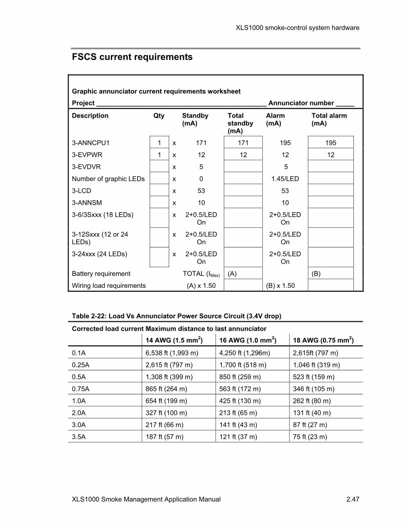
XLS1000 smoke-control system hardware
XLS1000 Smoke Management Application Manual 2.47
FSCS current requirements
Graphic annunciator current requirements worksheet
Project ______________________________________________ Annunciator number _____
Description Qty Standby (mA)
Total standby (mA)
Alarm (mA)
Total alarm (mA)
3-ANNCPU1 1 x 171 171 195 195
3-EVPWR 1 x 12 12 12 12
3-EVDVR x 5 5
Number of graphic LEDs x 0 1.45/LED
3-LCD x 53 53
3-ANNSM x 10 10
3-6/3Sxxx (18 LEDs) x 2+0.5/LED On
2+0.5/LED On
3-12Sxxx (12 or 24 LEDs)
x 2+0.5/LED On
2+0.5/LED On
3-24xxx (24 LEDs) x 2+0.5/LED On
2+0.5/LED On
Battery requirement TOTAL (IMax) (A) (B)
Wiring load requirements (A) x 1.50 (B) x 1.50
Table 2-22: Load Vs Annunciator Power Source Circuit (3.4V drop)
Corrected load current Maximum distance to last annunciator
14 AWG (1.5 mm2) 16 AWG (1.0 mm2) 18 AWG (0.75 mm2)
0.1A 6,538 ft (1,993 m) 4,250 ft (1,296m) 2,615ft (797 m)
0.25A 2,615 ft (797 m) 1,700 ft (518 m) 1,046 ft (319 m)
0.5A 1,308 ft (399 m) 850 ft (259 m) 523 ft (159 m)
0.75A 865 ft (264 m) 563 ft (172 m) 346 ft (105 m)
1.0A 654 ft (199 m) 425 ft (130 m) 262 ft (80 m)
2.0A 327 ft (100 m) 213 ft (65 m) 131 ft (40 m)
3.0A 217 ft (66 m) 141 ft (43 m) 87 ft (27 m)
3.5A 187 ft (57 m) 121 ft (37 m) 75 ft (23 m)

XLS1000 smoke-control system hardware
2.48 XLS1000 Smoke Management Application Manual
Wiring diagrams
Relay control with LED/switch displays There are numerous smoke-control applications which require the use of automatic relays to control related systems within a smoke zone. These controls must be provided with manual override switches and status LEDs at the FSCS. The custom FSCS series annunciator with three-position EVSC3 series toggle switches can serve this function.
Fan Control and Monitor
This application requires two interlocked relays to start and stop a fan. An independent air flow switch is provided to monitor the fan status.
Off
Off_Relay_1
On
CR, MCR, or UM CR, MCR, or UM
On_Relay_1
[SMOKE212.CDR]
ON
AUTO
OFF
On_LED_1a ON_Switch_1
Auto_Switch_1Off_Switch_1
Auto_LED_1b
Off_LED_1c
OperationOn Relay:
Off Relay:
Auto switch:
Airflow switch:
Operates when commanded to operate by "on" switch.
Programmed to turn on when any alarm device activates and when commanded to operate by "off" switch.
returns fan to automatic operation and lights "Auto" LED.
operates on and off LEDS, indicating fan status.
Fanmotor
Motor controller
HVAC system fancontrol contact
Smoke-control fanshut down contactSmoke-control fan
turn on contact
Pri
OLM
M1
OffOnAuto
Sec
L1
L2
L3
CT1 or MCT2*
*See Detail for MCT2.
MCT2
Monitor_1
Airflow switch
Personalitycode 4
UIO2R or UIO6R
1234
47 kEOL
Ω
Detail
ToMCR
Figure 2-11: Fan Control and Monitor

XLS1000 smoke-control system hardware
XLS1000 Smoke Management Application Manual 2.49
Damper Control and Monitor
For smoke-control, this application requires two interlocked relays to open and close a damper. The position of the damper must be indicated on the control panel during active alarm conditions. Confirmation of the damper in the zone-required position is indicated on the graphic annunciator panel and LED.
[SMOKE213.CDR]
Open Close
CR, MCR,or UM
CR, MCR,or UM
SupDamp_Close_Relay_1SupDamp_Open_Relay_1
OPEN
AUTO
CLOSE
SupDamp_Open_LED_1a SupDamp_Open_Switch_1
SupDamp_Auto_Switch_1
SupDamp_Close_Switch_1
SupDamp_Auto_LED_1b
SupDamp_Close_LED_1c
CT2 or MCT2
SupDamp_Open_Monitor_1a
SupDamp_Close_Monitor_1c
Open limit switch
Closed limit switch
Dampermotor
OpenL
N
Close
Neutral
Smoke-control damper open and close relay contacts
Damper open andclose limit switches
Operation
1 Open Relay: Programmed to operate when any device on another floor activates and when commanded to operate by "open" switch.
2 Close Relay: Programmed to operate when any automatic device on fire floor activates and when commanded to operate by "close" switch.
3 Limit switches operate open and closed LEDs, indicating damper position.
4 "Auto" switch returns damper to automatic operation (steps 1 and 2) and lights "Auto" LED.
Figure 2-12: Damper control with status indicators

XLS1000 smoke-control system hardware
2.50 XLS1000 Smoke Management Application Manual
ARA-1 Wiring
4
12
8
1
9
5
14 13
ARA-1
From +24Vdccontrol source
From -24Vdccontrol source
To normally closed,held open application
To normally closed,held open application
To normally open,held closed application
To normally open,held closed application
24VDC Relay
+24 Vdc -24 Vdc
Control Voltage Wiring
TransientProtection
Diode
Note: +24Vdc control voltage is connectedto cathode (banded end) of diode.
Relay Base Pin Designations
1 (K1B-N.C.)(K1A-N.C.) 4
9 (K1B-COM)(K1A-COM) 12
5 (K1B-N.O.)(K1A-N.O.) 8
13 (-24Vdc)(+24Vdc) 14
Note: Relay contact terminal normally-open (N.O.) and normally-closed (N.C.) designations are assigned when the relay is non-energized.
Note: Application wiringassumes normal operationof relay is in the non-energized state.
Relay Contact
Pin 12 to Pin 8 Open
Open
Pin 12 to Pin 4 Closed
Closed
Closed
ClosedPin 9 to Pin 5
Pin 9 to Pin 1
Non-energized Energized
Open
Open
RELAY STATE TABLE
K1A
K1B
[SMOKE214.CDR] Figure 2-13: ARA-1 Wiring Diagram

XLS1000 smoke-control system hardware
XLS1000 Smoke Management Application Manual 2.51
4 4
8 8
3 3
7 7
2 2
6 6
1 1
5 5
CT2 CT2
8 8 8 8 8
4 4 4 4 4
7 7 7 7 76 6 6 6 6
3 3 3 3 32 2 2 2 21 1 1 1 1
CR CR CR CR CT1
Supply FanSF-1
Exhaust FanEF-1
On OnOff Off
On OnOff Off
Data outto nextdevice
Data outto nextdevice
To Signatureloop controller
+24 Vdc
- 24 Vdc
+ - + - + - + - + - + -+ - + -
+ - + - + - + -
+ - + -
11
1 The NFPA 72 Code requires that the wire distance between Control Devices and Air Handling Units NOT exceed 36" (91.44 cm).
2 3-PPS/M or 3-BPS/M power supply.
3 A diode (P/N IN4001) must be installed across terminals 13 and 14 of each ARA-1 to prevent back EMF.
4 Relay contact terminal normally-open (N.O) and normally-closed (N.C.) Designations are assigned when the relay is non-energized.
2
120 Vac 120 Vac
14 14 14 14 14
14
8 8 8 8 8
8
13 13 13 13 13
13
5 5 5 5 5
5
12 12 12 12 12
12
4 4 4 4 4
4
9 9 9 9 9
9
1 1 1 1 1
1
ARA-1 ARA-1 ARA-1 ARA-1 ARA-1
ARA-1
[SMOKE216.CDR]
47 k EOLΩ
Figure 2-14: 120 Vac HVAC Fan shutdown circuit
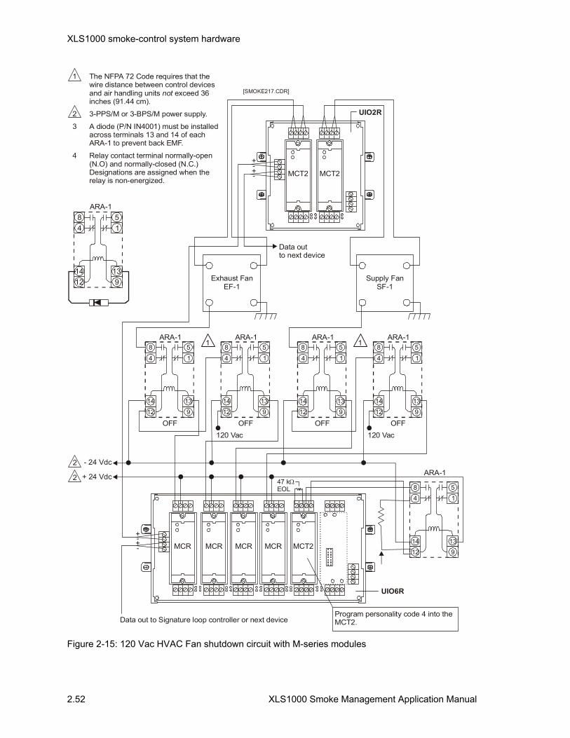
XLS1000 smoke-control system hardware
2.52 XLS1000 Smoke Management Application Manual
MCT2
Program personality code 4 into the MCT2.
MCR MCR MCR MCR
MCT2 MCT2
Exhaust FanEF-1
Supply FanSF-1
Data outto next device
Data out to Signature loop controller or next device
11
8
88 88
5
55 55
4
44 44
14
1414 1414
12
1212 1212
9
99 99
13
1313 1313
1
11 11
ARA-1
ARA-1ARA-1 ARA-1ARA-1
OFFOFF OFFOFF120 Vac120 Vac
[SMOKE217.CDR]
47 kEOL
Ω
Wiring Notes1 The NFPA 72 Code requires that the
wire distance between control devices and air handling units exceed 36 inches (91.44 cm).
2 3-PPS/M or 3-BPS/M power supply.
3 A diode (P/N IN4001) must be installed across terminals 13 and 14 of each ARA-1 to prevent back EMF.
4 Relay contact terminal normally-open (N.O) and normally-closed (N.C.) Designations are assigned when the relay is non-energized.
not
+ 24 Vdc
- 24 Vdc
2
2
UIO2R
UIO6R
++
++
--
--
14
8
13
5
12
4
9
1
ARA-1
Figure 2-15: 120 Vac HVAC Fan shutdown circuit with M-series modules

XLS1000 smoke-control system hardware
XLS1000 Smoke Management Application Manual 2.53
Wiring Notes
1 Code requires that the wire distance between control devices and air handling units exceed 36 inches (91.44 cm).
not
CR
CR
CT2
ARA-1 FAN/AHU
ARA-1
+24 Vdc
+24 Vdc
To Signatureloop controller
6Run
47 k EOLΩ
47 k EOLΩ
Stop/Fault
6
3
3
7
7
5
7
5
5
8
8
4
4
2
4
3
3
1
3
120 VAC from fan
1
8
6
1
1
1
1
[SMOKE215.CDR]
On
Off
Figure 2-16: Fan shutdown circuit

XLS1000 smoke-control system hardware
2.54 XLS1000 Smoke Management Application Manual
1 Code requires that the wire distance between Control Devices and Air Handling Units exceed 36 inches (91.44 cm).not
MCR
MCR
MCT2
TB1
TB2
TB3
TB7
UIO6R
ARA-1 FAN/AHU
ARA-1
+24 Vdc
+24 Vdc
3
47 k EOLΩ
47 k EOLΩ
Stop/Fault
Run
3
4
23
1
3
3
2
2
5
5
1
1
4321
120 Vac from fan
1
1
1
1
1
[SMOKE218.CDR]
On
Off
++__
Figure 2-17: Fan shutdown circuit with Signature M-series modules

XLS1000 Smoke Management Application Manual 3.1
Chapter 3 Smoke-control system programming
Summary
This chapter provides information and procedures required to write programming rules for smoke-control system functions.
Content
Programming smoke-control•3.2 Fundamentals•3.2 Before you begin•3.3
Understanding objects, labels, and rules•3.4 Objects•3.4 Labels•3.4 Rules•3.4
Developing a labeling plan•3.6 Formatting labels•3.6
Smoke-control considerations and sequencing•3.8 Smoke-control functions•3.8 Using “AND” groups for smoke-control•3.8 System Response time•3.10
Rules for smoke-control programming•3.11 Rule example•3.15
Example 3-1•3.15 HVAC and system control examples•3.18
Dedicated systems•3.18 Dedicated smoke-control stair tower rules example•3.19 Single zone smoke-control systems with direct outside air and direct exhaust air•3.19 Single zone smoke-control system rules example•3.20 Single zone smoke-control with common outside air and exhaust air•3.22 Central system smoke-control•3.23 Dual duct smoke-control•3.24 Dual duct smoke-control rules example•3.25 Multi-zone smoke-control•3.29 VAV smoke-control•3.29
Smoke-control system programming
3.2 XLS1000 Smoke Management Application Manual
Programming smoke-control All XLS1000 SCS and FSCS smoke-control application programming is done using rules and object programming as found in this chapter and in the XLS1000 Programming Manual. The advantages are numerous:
• Devices are referenced by their descriptive labels. There is no need to use device addresses.
• One rule can replace multiple individual device responses.
• Labels and device types simplify creating a device’s response.
• Group input and output functions are quickly implemented.
• Label processing tools are designed into the System Definition Utility.
The following line identifies a supply fan on the fourth floor of a building. The device address is the set of numbers to the left while the information on the right is a label for the device. The label reveals more information about the device point and its function than the numeric device label. 0118124 S_FAN_ON<4>
For smoke-control systems in a building, rules writing will center around smoke zones defined by physical barriers composed of walls and doors. Rules will result in control actions within a smoke zone where the fire is occurring and also in zones adjacent to the fire.
Fundamentals All smoke-control system processes may be divided into three fundamental parts: inputs, controls, and outputs. Examples of smoke-control system inputs are smoke detectors, pull stations, and sprinkler waterflow switches. Smoke-control outputs include: control relays for fans and dampers.
The relationship between the inputs and the outputs is determined by the control function of the smoke-control system. For a basic smoke-control system, this control function can be stated simply as: when smoke detector “A” activates, switch fan “A” on. As a smoke-control system becomes more complex, it will require a more sophisticated set of rules to make up the control function for multiple smoke zones.
The XLS1000 SCS system designer establishes a number of rules which define the operation of the system. Designers assign descriptive names or labels to smoke detectors, smoke zones, fan control relays, damper control relays, and monitor points. This aids the programming process by easily identifying all the

Smoke-control system programming
XLS1000 Smoke Management Application Manual 3.3
devices in the system, and eliminating the need to juggle long strings of address numbers.
UL smoke-control requirements state that only the first automatic response can activate automatic smoke-control functions. All subsequent changes in the operation of the smoke-control system must be performed manually at the SCS or the FSCS. In order to prevent subsequent adjacent smoke zones automatic responses from overriding the initial smoke-control actions centered in the fire area, “AND” groups are created for each smoke-control zone.
When an input goes active, the smoke-control system compares the device’s input label to all the rules stored in its memory. When a match is found between a device and a rule, the rule is executed. Executing the rule requires the smoke-control system to again search its memory for all output device labels which match the rule. The matching output devices are then turned on or off, as specified in the rule.
Non-smoke-control functions: All device responses for non-smoke-control functions such as elevator capture, unlocking doors, etc. should not be programmed in with smoke-control functions despite their location within a smoke-control zone.
Before you begin The XLS1000 SCS uses a system of rules and objects to define the relationships between the system inputs and outputs. This is the same criterion used for the XLS1000 system. Critical to the use of these rules is the naming of the objects making up the system. When properly labeled, the true power of the XLS1000 rules and object programming is revealed.
Before you begin configuring a system, you should take the time to:
• Make sure you understand the concepts of objects, labels, and rules
• Develop a labeling plan centered around smoke-control zone “AND” groups
• Identify the objects in the system and determine the relationships between the inputs and outputs

Smoke-control system programming
3.4 XLS1000 Smoke Management Application Manual
Understanding objects, labels, and rules
Objects An object is any addressable device or circuit in the system that can be used to initiate an input event in a rule or can be the subject of an output action. An object may be:
• A physical system component such as: a Local Rail Module (LRM), a smoke detector, or a light emitting diode (LED)
• A logic group comprised of physical system components
• An artificial internal point, sometimes referred to as a pseudo point, designed into the system to monitor system events.
For example, the 3-SSDC Single Signature Driver Controller is an object as are the Signature-series detectors connected to it. In contrast, the 3-IDC8/4 Initiating Device Circuit is an object, each of its eight zones are objects.
Labels A label is any descriptive word or words created by the XLS1000 SCS system designer to identify a specific object in the database. Labels are also used to identify a rule. Labels have the following characteristics:
• Labels must be unique. Duplicate labels will generate compiler errors and prevent you from compiling the database.
• Labels are arbitrary. They are assigned by XLS1000 SCS system designers to simplify programming.
• Labels may contain up to forty characters. The characters may be any ASCII character except: braces “ ”, the percent symbol “%”, asterisks “*”, and blank spaces. You should generally try to limit LRM labels to twenty characters.
Labels are not case sensitive and in some cases are automatically assigned by the system. For example, the system will automatically assign labels for pseudo points on the 3-CPU1, 3-LCD, and other LRMs.
Rules A rule is a statement specifying what operation or operations will occur when a certain event takes place. A rule is composed of an input statement and an output statement, separated by a colon and ended with a semicolon. When the conditions are met to make the input statement true (active), then the system will respond as directed by the output statement.

Smoke-control system programming
XLS1000 Smoke Management Application Manual 3.5
[Rule Label] Input_Statement:Output_Statement;
If a rule has four operations, designated output_command_1, output_command_2, output_command_3, and output_command_4, they will be performed in the order they are listed in the rule when the rule is executed. When the event activating the rule restores, the operations performed by the rule will automatically restore in the reverse order.

Smoke-control system programming
3.6 XLS1000 Smoke Management Application Manual
Developing a labeling plan Programming an XLS1000 SCS will require that you assign labels to cabinets, modules, and other objects in the database. Before you start programming, you need to develop a labeling plan. By developing a labeling plan, you will ensure that your labels will be understandable and useful. This chapter contains examples of labels for various types of HVAC system configurations which are used in smoke-control.
There are five things you should consider in your labeling plan:
• Label format • Label content • Use of common label modifiers • Label numbering • Use of labels as messages
Formatting labels To make your labels more readable, and more understandable, your plan should include how labels will be formatted. You should take into consideration that labels will be viewed on-line, on printed reports and on the system display panel. Formatting considerations may include:
• How to separate label modifiers • Whether to use all uppercase or all lowercase characters or a
combination of both • How label modifiers may be abbreviated
Functionally, it makes no difference whether your labels contain upper or lowercase characters.
Example: Methods for formatting labels. The following shows three examples using different methods of label formatting for a smoke zone in the building: LEVEL1AREA1 LEVEL1_AREA1 Level1_Area1
The first label may be hard to read because it uses all uppercase characters and there is no separation between the label modifiers LEVEL1 and AREA1. The second label places an underscore between the two modifiers which makes it easier to read. The third label uses upper and lowercase characters to differentiate between label modifiers.
Some tips to consider when formatting labels:
• Be consistent. Consistency is the most important factor in making your labels easy to use and understand. You want to avoid using LEVEL1, LEVEL_1, and Level1as label modifiers to reference the same building.
The most important thing to remember about formatting labels is to be consistent.
All labels must be unique. Duplicate labels are not allowed.

Smoke-control system programming
XLS1000 Smoke Management Application Manual 3.7
• Find a comfortable balance between readability and length. Adding extra underscores to separate label modifiers, as in LEVEL1_AREA1_S_DMP_OP 5, may make the label more readable but unnecessarily adds to the length.
Remote annunciator programming configuration instructions
The FSCS series annunciators are configured as part of the system using the program. Each annunciator for a project must be configured as a separate Cabinet (Node). Use the substitutions indicated in the Table below to define each Graphic Annunciator in the system.
Table 3-1: Graphic annunciator programming substitutions
Annunciator Components Substitute Entry
For each annunciator add one Cabinet. 32 Cabinets maximum per system including all panels.
xxx-CAB21
In Slot 3 remove the ‘3-PS/M’ by configuring the LRM Type as ‘None’
Slot 3 ‘None’
The first LED/Sw Driver Module is added to Slot 4 as a 3-LDSM on the Hardware Layer and a 12SW/24LED on the Operator Layer.
Slot 4 3-LDSM 12SW/24LED
Add additional LED/Sw Driver Modules as required to subsequent slots as a 3-LDSM on the Hardware Layer and a 12SW/24LED on the Operator Layer.
Subsequent Slots 3-LDSM 12SW/24LED
Note: There are no RS-232 ports or common relay contacts available on the 3-ANNCPU1.
Smoke-control system programming
3.8 XLS1000 Smoke Management Application Manual
Smoke-control considerations and sequencing
Smoke-control functions For the XLS1000 smoke-control system only the first automatic response can activate automatic smoke-control functions. All subsequent changes to the smoke-control system must be done manually at the FSCS. In order to prevent subsequent automatic responses from overriding and affecting the smoke-control functions of the zone where the fire is, “AND” groups are used as follows:
• An “AND” group must be created for each smoke zone.
• The elements contained in the “AND” group must be all of the automatic and manual alarm initiating devices which automatically initiate the smoke-control function for a particular smoke-control zone.
• Each “AND” group used for smoke-control MUST have its activation number set at one (1).
• Each “AND” group activates the automatic smoke-control functions for its respective smoke zone.
• Upon receipt of an alarm the ‘fire’ smoke-controls “AND” group must disable all other smoke-control “AND” groups.
Using “AND” groups for smoke-control [ALARM ‘AND_Group1’]
ALARM ‘AND_Group1’is an AND group which contains all initiating devices in smoke zone #1. The activation number =1
[ALARM ‘AND_Group2’]
ALARM ‘AND_Group2’ is an AND group which contains all initiating devices in smoke zone #2. The activation number =1
[ALARM ‘AND_Group3’]
ALARM ‘AND_Group3’ is an AND group which contains all initiating devices in smoke zone #3. The activation number =1
Example [ALARM ‘AND_Group1’]
ALARM ‘AND_GROUP1’ :
ON –LOW ‘ZONE_1_DOOR_CLOSE’,
STEADY ‘ZONE_1_DOOR_CLOSE_LED*’,
ON DMP ‘ZONE_1_EXHAUST_DAMPER_OPEN’,
ON –HIGH ‘ZONE_1_EXHAUST_DAMPER_AUTO’,

Smoke-control system programming
XLS1000 Smoke Management Application Manual 3.9
STEADY ‘ZONE_1_EXHAUST_DAMPER_OPEN_LED*’,
ON –LOW ‘ZONE_1_SUPPLY_DAMPER_CLOSE’,
ON –HIGH ‘ZONE_1_SUPPLY_DAMPER_AUTO’,
STEADY ‘ZONE_1_SUPPLY_DAMPER_CLOSE_LED*’,
ON LOW ‘ZONE_2_EXHAUST_DAMPER_CLOSE’,
ON –HIGH ‘ZONE_2_EXHAUST_DAMPER_AUTO’,
STEADY ‘ZONE_2_EXHAUST_DAMPER_CLOSE_LED*’,
ON –LOW ‘ZONE_2_SUPPLY_DAMPER_OPEN’,
ON –HIGH ‘ZONE_2_SUPPLY_DAMPER_AUTO’,
STEADY ‘ZONE_2_SUPPLY_DAMPER_OPEN_LED*,
DLYA 0075,
ON –HIGH ‘ZONE_1_SUPPLY_FAN_OFF’,
ON –HIGH ‘ZONE_1_SUPPLY_FAN_AUTO’,
STEADY –HIGH ‘ZONE_1_SUPPLY_FAN_OFF_LED*’,
ON –HIGH ‘ZONE_2_EXHAUST_FAN_OFF’,
ON –HIGH ‘ZONE_2_EXHAUST_FAN_AUTO’,
STEADY –HIGH ‘ZONE_2_EXHAUST_FAN_OFF_LED*’,
ON –HIGH ‘ZONE_2_SUPPLY_FAN_ON’,
ON –HIGH ‘ZONE_2_SUPPLY_FAN_AUTO’,
STEADY –HIGH ‘ZONE_2_SUPPLY_FAN_ON_LED*’,
ON –HIGH ‘ZONE_1_EXHAUST_FAN_ON’,
ON –HIGH ‘ZONE_1_EXHAUST_FAN_AUTO’,
STEADY –HIGH ‘ZONE_1_EXHAUST_FAN_ON_LED*’,
DLYA 60,
ON –HIGH ‘ZONE_1_SUPPLY_FAN_OFF_TROUBLE’,
FAST –HIGH ‘ZONE_1_SUPPLY_FAN_OFF_TROUBLE_LED’,
ON –HIGH ‘ZONE_2_EXHAUST_FAN_OFF_TROUBLE’,
FAST –HIGH ‘ZONE_2_EXHAUST_FAN_OFF_TROUBLE_LED’;
[DISABLE AND_GROUP]
ALARM ‘AND_GROUP1’ :
DISABLE ‘AND_GROUP2’,
DISABLE ‘AND_GROUP3’,
DISABLE ‘AND_GROUP4’,
DLYA 30;

Smoke-control system programming
3.10 XLS1000 Smoke Management Application Manual
System Response time Smoke-control activation is to be initiated immediately after receipt of an appropriate automatic or manual activation command. Smoke-control systems activate individual components such as fans and dampers in a sequence necessary to prevent physical damage to equipment. The total response time for individual components to achieve operational mode should remain within the limits set in NFPA 92A as a base requirement:
• 60 seconds for fan operation at smoke system design rate • 75 seconds for isolating damper travel
The Uniform Building Code (UBC), one of the three model building codes in use in the US, establishes more restrictive limits on smoke-control system response times. Section 905.14 of the UBC requires individual components to achieve their desired operating mode according to device:
Table 3-2 UBC response time requirements
Component Response time
Control air isolation valves Immediately
Smoke damper closing 15 seconds
Smoke damper openings 15 seconds maximum
Fan starting (energizing) 15 seconds maximum
Fan stopping (de-energizing) Immediately
Fan volume modulation 30 seconds maximum
Pressure control modulation 15 seconds maximum
Temperature control safety override 15 seconds maximum
Positive indication of status 15 seconds maximum
Note: Local codes may require different response times.
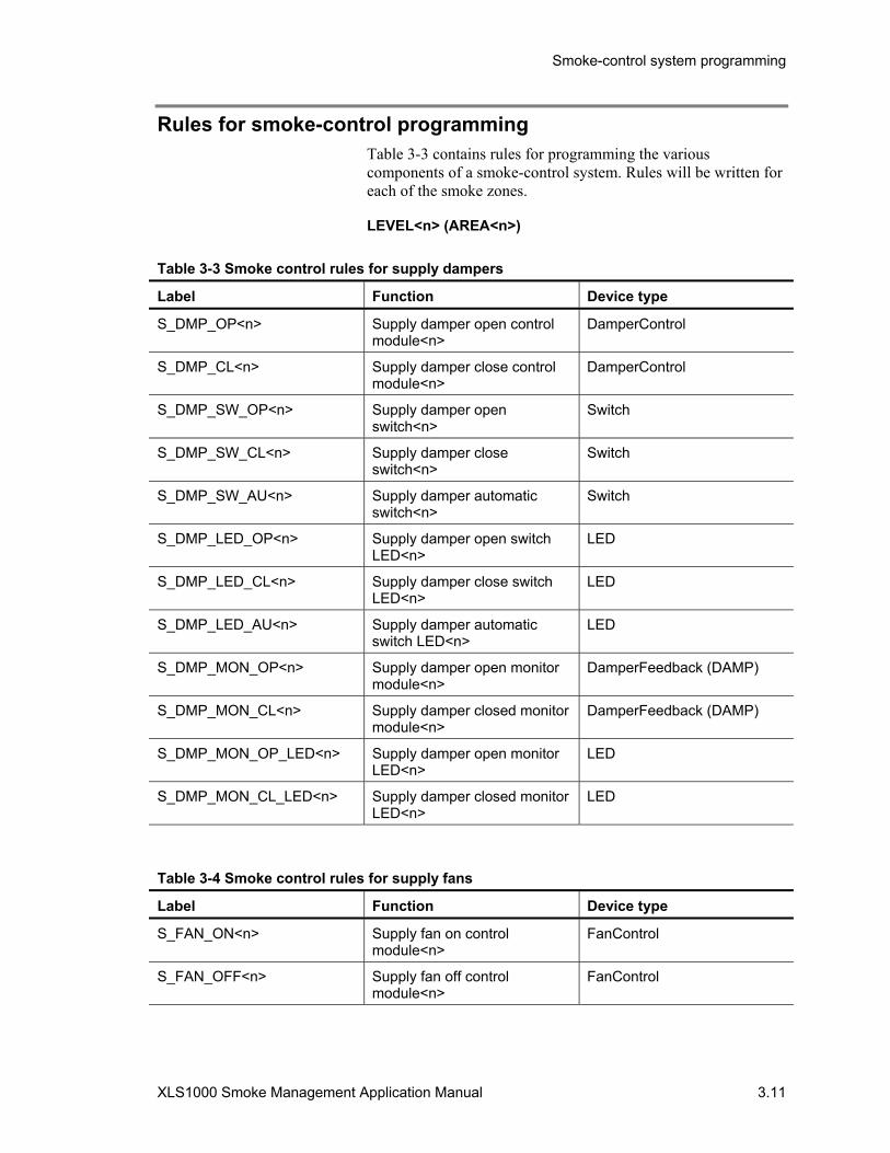
Smoke-control system programming
XLS1000 Smoke Management Application Manual 3.11
Rules for smoke-control programming Table 3-3 contains rules for programming the various components of a smoke-control system. Rules will be written for each of the smoke zones.
LEVEL<n> (AREA<n>)
Table 3-3 Smoke control rules for supply dampers
Label Function Device type
S_DMP_OP<n> Supply damper open control module<n>
DamperControl
S_DMP_CL<n> Supply damper close control module<n>
DamperControl
S_DMP_SW_OP<n> Supply damper open switch<n>
Switch
S_DMP_SW_CL<n> Supply damper close switch<n>
Switch
S_DMP_SW_AU<n> Supply damper automatic switch<n>
Switch
S_DMP_LED_OP<n> Supply damper open switch LED<n>
LED
S_DMP_LED_CL<n> Supply damper close switch LED<n>
LED
S_DMP_LED_AU<n> Supply damper automatic switch LED<n>
LED
S_DMP_MON_OP<n> Supply damper open monitor module<n>
DamperFeedback (DAMP)
S_DMP_MON_CL<n> Supply damper closed monitor module<n>
DamperFeedback (DAMP)
S_DMP_MON_OP_LED<n> Supply damper open monitor LED<n>
LED
S_DMP_MON_CL_LED<n> Supply damper closed monitor LED<n>
LED
Table 3-4 Smoke control rules for supply fans
Label Function Device type
S_FAN_ON<n> Supply fan on control module<n>
FanControl
S_FAN_OFF<n> Supply fan off control module<n>
FanControl
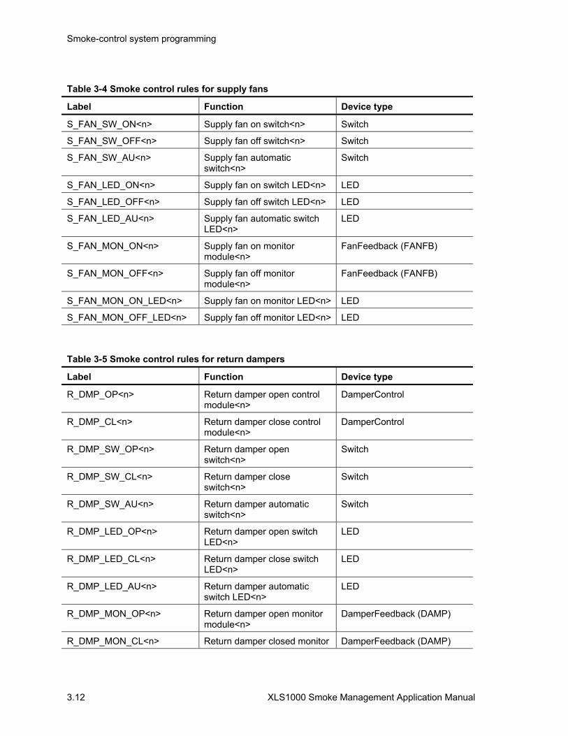
Smoke-control system programming
3.12 XLS1000 Smoke Management Application Manual
Table 3-4 Smoke control rules for supply fans
Label Function Device type
S_FAN_SW_ON<n> Supply fan on switch<n> Switch
S_FAN_SW_OFF<n> Supply fan off switch<n> Switch
S_FAN_SW_AU<n> Supply fan automatic switch<n>
Switch
S_FAN_LED_ON<n> Supply fan on switch LED<n> LED
S_FAN_LED_OFF<n> Supply fan off switch LED<n> LED
S_FAN_LED_AU<n> Supply fan automatic switch LED<n>
LED
S_FAN_MON_ON<n> Supply fan on monitor module<n>
FanFeedback (FANFB)
S_FAN_MON_OFF<n> Supply fan off monitor module<n>
FanFeedback (FANFB)
S_FAN_MON_ON_LED<n> Supply fan on monitor LED<n> LED
S_FAN_MON_OFF_LED<n> Supply fan off monitor LED<n> LED
Table 3-5 Smoke control rules for return dampers
Label Function Device type
R_DMP_OP<n> Return damper open control module<n>
DamperControl
R_DMP_CL<n> Return damper close control module<n>
DamperControl
R_DMP_SW_OP<n> Return damper open switch<n>
Switch
R_DMP_SW_CL<n> Return damper close switch<n>
Switch
R_DMP_SW_AU<n> Return damper automatic switch<n>
Switch
R_DMP_LED_OP<n> Return damper open switch LED<n>
LED
R_DMP_LED_CL<n> Return damper close switch LED<n>
LED
R_DMP_LED_AU<n> Return damper automatic switch LED<n>
LED
R_DMP_MON_OP<n> Return damper open monitor module<n>
DamperFeedback (DAMP)
R_DMP_MON_CL<n> Return damper closed monitor DamperFeedback (DAMP)

Smoke-control system programming
XLS1000 Smoke Management Application Manual 3.13
Table 3-5 Smoke control rules for return dampers
Label Function Device type module<n>
R_DMP_MON_OP_LED<n> Return damper open monitor LED<n>
LED
R_DMP_MON_CL_LED<n> Return damper closed monitor LED<n>
LED
Table 3-6 Smoke control rules for return fans
Label Function Device type
R_FAN_ON<n> Return fan on control module<n>
FanControl
R_FAN_OFF<n> Return fan off control module<n>
FanControl
R_FAN_SW_ON<n> Return fan on switch<n> Switch
R_FAN_SW_OFF<n> Return fan off switch<n> Switch
R_FAN_SW_AU<n> Return fan automatic switch<n>
Switch
R_FAN_LED_ON<n> Return fan on switch LED<n> LED
R_FAN_LED_OFF<n> Return fan off switch LED<n> LED
R_FAN_LED_AU<n> Return fan automatic switch LED<n>
LED
R_FAN_MON_ON<n> Return fan on monitor module<n>
FanFeedback (FANFB)
R_FAN_MON_OFF<n> Return fan off monitor module<n>
FanFeedback (FANFB)
R_FAN_MON_ON_LED<n> Return fan on monitor LED<n> LED
R_FAN_MON_OFF_LED<n> Return fan off monitor LED<n> LED
Table 3-7 Smoke control rules for exhaust dampers
Label Function Device type
E_DMP_OP<n> Exhaust damper open control module<n>
DamperControl
E_DMP_CL<n> Exhaust damper close control module<n>
DamperControl
E_DMP_SW_OP<n> Exhaust damper open switch<n> Switch

Smoke-control system programming
3.14 XLS1000 Smoke Management Application Manual
Table 3-7 Smoke control rules for exhaust dampers
Label Function Device type
E_DMP_SW_CL<n> Exhaust damper close switch<n> Switch
E_DMP_SW_AU<n> Exhaust damper automatic switch<n> Switch
E_DMP_LED_OP<n> Exhaust damper open switch LED<n> LED
E_DMP_LED_CL<n> Exhaust damper close switch LED<n> LED
E_DMP_LED_AU<n> Exhaust damper automatic switch LED<n>
LED
E_DMP_MON_OP<n> Exhaust damper open monitor module<n>
DamperFeedback (DAMP)
E_DMP_MON_CL<n> Exhaust damper closed monitor module<n>
DamperFeedback (DAMP)
E_DMP_MON_OP_LED<n> Exhaust damper open monitor LED<n>
LED
E_DMP_MON_CL_LED<n> Exhaust damper closed monitor LED<n>
LED
E_FAN_ON<n> Exhaust fan on control module<n> FanControl
E_FAN_OFF<n> Exhaust fan off control module<n> FanControl
E_FAN_SW_ON<n> Exhaust fan on switch<n> Switch
E_FAN_SW_OFF<n> Exhaust fan off switch<n> Switch
E_FAN_AU_OFF<n> Exhaust fan automatic switch<n> Switch
E_FAN_LED_ON<n> Exhaust fan on switch LED<n> LED
E_FAN_LED_OFF<n> Exhaust fan off switch LED<n> LED
E_FAN_LED_AU<n> Exhaust fan automatic switch LED<n> LED
E_FAN_MON_ON<n> Exhaust fan on monitor module<n> FanFeedback (FANFB)
E_FAN_MON_OFF<n> Exhaust fan off monitor module<n> FanFeedback (FANFB)
E_FAN_MON_ON_LED<n> Exhaust fan on monitor LED<n> LED
E_FAN_MON_OFF_LED<n> Exhaust fan off monitor LED<n> LED
*Fan and damper control switches are 3-6/3S1Gxx configured as interlocked switches.
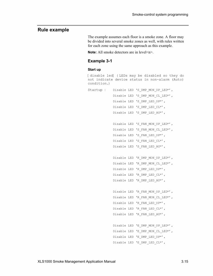
Smoke-control system programming
XLS1000 Smoke Management Application Manual 3.15
Rule example The example assumes each floor is a smoke zone. A floor may be divided into several smoke zones as well, with rules written for each zone using the same approach as this example.
Note: All smoke detectors are in level<n>.
Example 3-1
Start up [disable led] LEDs may be disabled so they do not indicate device status in non-alarm (Auto) condition.
Startup : Disable LED ‘S_DMP_MON_OP_LED*’,
Disable LED ‘S_DMP_MON_CL_LED*’,
Disable LED ‘S_DMP_LED_OP*’, Disable LED ‘S_DMP_LED_CL*’,
Disable LED ‘S_DMP_LED_AU*’,
Disable LED ‘S_FAN_MON_OP_LED*’,
Disable LED ‘S_FAN_MON_CL_LED*’,
Disable LED ‘S_FAN_LED_OP*’, Disable LED ‘S_FAN_LED_CL*’,
Disable LED ‘S_FAN_LED_AU*’, Disable LED ‘R_DMP_MON_OP_LED*’,
Disable LED ‘R_DMP_MON_CL_LED*’,
Disable LED ‘R_DMP_LED_OP*’, Disable LED ‘R_DMP_LED_CL*’,
Disable LED ‘R_DMP_LED_AU*’,
Disable LED ‘R_FAN_MON_OP_LED*’,
Disable LED ‘R_FAN_MON_CL_LED*’,
Disable LED ‘R_FAN_LED_OP*’, Disable LED ‘R_FAN_LED_CL*’,
Disable LED ‘R_FAN_LED_AU*’, Disable LED ‘E_DMP_MON_OP_LED*’,
Disable LED ‘E_DMP_MON_CL_LED*’,
Disable LED ‘E_DMP_LED_OP*’, Disable LED ‘E_DMP_LED_CL*’,

Smoke-control system programming
3.16 XLS1000 Smoke Management Application Manual
Disable LED ‘E_DMP_LED_AU*’,
Disable LED ‘E_FAN_MON_OP_LED*’,
Disable LED ‘E_FAN_MON_CL_LED*’,
Disable LED ‘E_FAN_LED_OP*’, Disable LED ‘E_FAN_LED_CL*’,
Disable LED ‘E_FAN_LED_AU*’;
[auto fan] set fan control modules to required normal states
Startup:
Programming note: you may wish to disable all the fan control switches so they will not operate when the HVAC system is in the Auto mode.
Switches [Switch SUPPLY_FAN_ON] Manual Switch Programing
SW ‘ZONE_<N:1-4>_SUPPLY_FAN_ON_SWITCH*’ : FANON –HIGH_’ZONE_<N>_SUPPLY_FAN_ON’,
FAST ‘ZONE_<N>_SUPPLY_FAN_MAN_ON_LED*’,
FAST ‘SUPPLY_FAN_MAN_ON_LED’,
SLOW ‘ZONE_<N>_SUPPLY_FAN_AUTO’,
ON –HIGH ‘ZONE_<N>_SUPPLY_FAN_AUTO’,
OFF –HIGH ‘ZONE_<N>_SUPPLY_FAN_OFF’,
OFF –HIGH ‘ZONE_<N>_SUPPLY_FAN_OFF_LED*’,
DLYA 60,
ON ‘ZONE_1_SUPPLY_FAN_ON_TROUBLE’,
FAST ‘ZONE_1_SUPPLY_FAN_ON_TROUBLE_LED’,
FAST ‘SUPPLY_FAN_ON_TROUBLE_LED*’;
[Switch SUPPLY_FAN_OFF]
SW ‘ZONE_<N:1-4>_MAN_SUPPLY_FAN_OFF_SWITCH*’ :
ON –HIGH_’ZONE_<N>_SUPPLY_FAN_OFF’,
FAST ‘ZONE_<N>_MAN_SUPPLY_FAN_OFF_LED*’,
FAST ‘SUPPLY_FAN_MAN_OFF_LED’,
SLOW ‘ZONE_<N>_SUPPLY_FAN_OFF_LED*’,
ON –HIGH ‘ZONE_<N>_SUPPLY_FAN_AUTO’,
OFF –HIGH ‘ZONE_<N>_SUPPLY_FAN_ON’,
OFF –HIGH ‘ZONE_<N>_SUPPLY_FAN_ON_LED*’,
DLYA 60
ON ‘ZONE_1_SUPPLY_FAN_OFF_TROUBLE’,
FAST ‘ZONE_1_SUPPLY_FAN_OFF_TROUBLE_LED’,
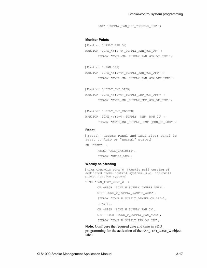
Smoke-control system programming
XLS1000 Smoke Management Application Manual 3.17
FAST ‘SUPPLY_FAN_OFF_TROUBLE_LED*’;
Monitor Points [Monitor SUPPLY_FAN_ON]
MONITOR ‘ZONE_<N:1-4>_SUPPLY_FAN_MON_ON’ :
STEADY ‘ZONE_<N>_SUPPLY_FAN_MON_ON_LED*’;
[Monitor S_FAN_OFF]
MONITOR ‘ZONE_<N:1-4>_SUPPLY_FAN_MON_OFF’ :
STEADY ‘ZONE_<N>_SUPPLY_FAN_MON_OFF_LED*’;
[Monitor SUPPLY_DMP_OPEN]
MONITOR ‘ZONE_<N:1-4>_SUPPLY_DMP_MON_OPEN’ :
STEADY ‘ZONE_<N>_SUPPLY_DMP_MON_OP_LED*’;
[Monitor SUPPLY_DMP_CLOSED]
MONITOR ‘ZONE_<N:1-4>_SUPPLY_ DMP _MON_CL’ :
STEADY ‘ZONE_<N>_SUPPLY_ DMP _MON_CL_LED*’;
Reset [reset] Resets Panel and LEDs after Panel is reset to Auto or “normal” state.
SW ‘RESET’ :
RESET ‘ALL_CABINETS’,
STEADY ‘RESET_LED’;
Weekly self-testing [TIME CONTROLS ZONE W] Weekly self testing of dedicated smoke-control systems. i.e. stairwell pressurization systems
TIME ‘FAN_TEST_ZONE_W’ :
ON –HIGH ‘ZONE_W_SUPPLY_DAMPER_OPEN’,
OFF ‘ZONE_W_SUPPLY_DAMPER_AUTO’,
STEADY ‘ZONE_W_SUPPLY_DAMPER_ON_LED*’,
DLYA 60,
ON –HIGH ‘ZONE_W_SUPPLY_FAN_ON’,
OFF –HIGH ‘ZONE_W_SUPPLY_FAN_AUTO’,
STEADY ‘ZONE_W_SUPPLY_FAN_ON_LED’;
Note: Configure the required date and time in SDU programming for the activation of the FAN_TEST_ZONE_W object label.

Smoke-control system programming
3.18 XLS1000 Smoke Management Application Manual
HVAC and system control examples
Dedicated systems
Table 3-8: Dedicated smoke-control stair tower
Smoke-control sequence commands Objective
1 Open supply air dampers for smoke control Provide a fresh air source to dilute smoke which may enter stair
2 Open exhaust air dampers for smoke zone Outlet vent for air in stair
3 Start stair tower smoke exhaust fan Pull air through exhaust damper
*Monitor at panel(s) air flow and damper position Confirms system operation and shut-in
SM
OK
E31
.CD
R
Fan
Exhaustdamper
Supplydamper
Figure 3-1: Dedicated smoke-control stair tower

Smoke-control system programming
XLS1000 Smoke Management Application Manual 3.19
Dedicated smoke-control stair tower rules example Auto Limit StairW is an AND group containing all initiating devices in stairtower W. The activation number =1. Disable AND Groups for other alarms would be added to this example
[Smoke Control StairW]
ALARM SMOKE ‘STAIRW’:
OPEN ‘S_DMP_OP_STAIRW’,
DLY 0060,
ON -HIGH ‘E_FAN_ON_STAIRW’;
[Monitor StairW E FAN OFF]
MONITOR ‘E_FAN_MON_OFF_StairW’:
STEADY ‘E_FAN_MON_OFF_StairW’;
[Monitor StairW E FAN ON]
MONITOR ‘E_FAN_MON_ON_StairW’:
STEADY ‘E_FAN_MON_ON_StairW’;
[Monitor StairW S DMP OPEN]
MONITOR ‘S_DMP_MON_OP_StairW’:
STEADY ‘S_DMP_MON_OP_StairW’;
[Monitor StairW E DMP OPEN]
MONITOR ‘E_DMP_MON_OP_StairW’:
STEADY ‘E_DMP_MON_OP_StairW’;
Single zone smoke-control systems with direct outside air and direct exhaust air
Table 3-9: Single zone smoke-control systems with direct outside air and direct exhaust air
Smoke-control sequence commands Objective
1 AUTO OFF Override all HVAC controls
2 Stop the smoke zone HVAC supply fan (Where fire is detected)
Reduce pressure development
3 Stop designated adjacent zone HVAC return fans Keep out smoke
4 Close smoke zone supply air dampers Stop smoke spread
5 Close adjacent zone return air dampers Keep out smoke
6 Open exhaust dampers for smoke zone Vent fire and develop negative pressure in smoke zone
7 Open outside air dampers for adjacent zone Develop positive pressure and keep out smoke
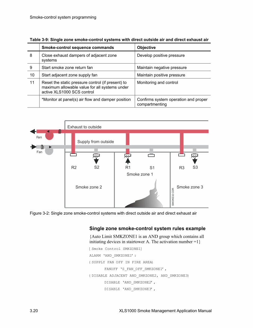
Smoke-control system programming
3.20 XLS1000 Smoke Management Application Manual
Table 3-9: Single zone smoke-control systems with direct outside air and direct exhaust air
Smoke-control sequence commands Objective
8 Close exhaust dampers of adjacent zone systems
Develop positive pressure
9 Start smoke zone return fan Maintain negative pressure
10 Start adjacent zone supply fan Maintain positive pressure
11 Reset the static pressure control (if present) to maximum allowable value for all systems under active XLS1000 SCS control
Monitoring and control
*Monitor at panel(s) air flow and damper position Confirms system operation and proper compartmenting
R2 S2 R1
Smoke zone 2
Smoke zone 1
Supply from outside
Exhaust to outside
Fan
Fan
SMO
KE32
.CD
R
S3
Smoke zone 3
R3
Figure 3-2: Single zone smoke-control systems with direct outside air and direct exhaust air
Single zone smoke-control system rules example Auto Limit SMKZONE1 is an AND group which contains all initiating devices in stairtower A. The activation number =1 [Smoke Control SMKZONE1]
ALARM ‘AND_SMKZONE1’:
SUPPLY FAN OFF IN FIRE AREA
FANOFF ‘S_FAN_OFF_SMKZONE1’,
DISABLE ADJACENT AND_SMKZONE2, AND_SMKZONE3
DISABLE ‘AND_SMKZONE2’,
DISABLE ‘AND_SMKZONE3’,
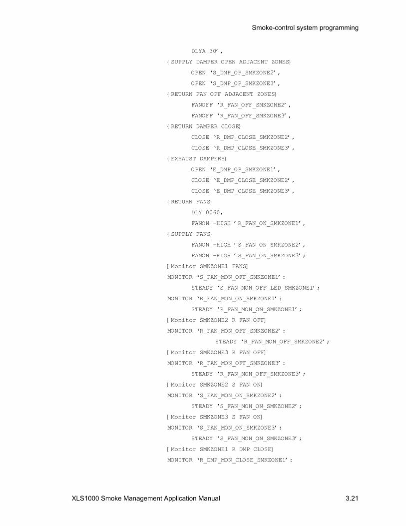
Smoke-control system programming
XLS1000 Smoke Management Application Manual 3.21
DLYA 30’,
SUPPLY DAMPER OPEN ADJACENT ZONES
OPEN ‘S_DMP_OP_SMKZONE2’,
OPEN ‘S_DMP_OP_SMKZONE3’,
RETURN FAN OFF ADJACENT ZONES
FANOFF ‘R_FAN_OFF_SMKZONE2’,
FANOFF ‘R_FAN_OFF_SMKZONE3’,
RETURN DAMPER CLOSE
CLOSE ‘R_DMP_CLOSE_SMKZONE2’,
CLOSE ‘R_DMP_CLOSE_SMKZONE3’,
EXHAUST DAMPERS
OPEN ‘E_DMP_OP_SMKZONE1’,
CLOSE ‘E_DMP_CLOSE_SMKZONE2’,
CLOSE ‘E_DMP_CLOSE_SMKZONE3’,
RETURN FANS
DLY 0060,
FANON –HIGH ’R_FAN_ON_SMKZONE1’,
SUPPLY FANS
FANON –HIGH ’S_FAN_ON_SMKZONE2’,
FANON –HIGH ’S_FAN_ON_SMKZONE3’;
[Monitor SMKZONE1 FANS]
MONITOR ‘S_FAN_MON_OFF_SMKZONE1’:
STEADY ‘S_FAN_MON_OFF_LED_SMKZONE1’;
MONITOR ‘R_FAN_MON_ON_SMKZONE1’:
STEADY ‘R_FAN_MON_ON_SMKZONE1’;
[Monitor SMKZONE2 R FAN OFF]
MONITOR ‘R_FAN_MON_OFF_SMKZONE2’:
STEADY ‘R_FAN_MON_OFF_SMKZONE2’;
[Monitor SMKZONE3 R FAN OFF]
MONITOR ‘R_FAN_MON_OFF_SMKZONE3’:
STEADY ‘R_FAN_MON_OFF_SMKZONE3’;
[Monitor SMKZONE2 S FAN ON]
MONITOR ‘S_FAN_MON_ON_SMKZONE2’:
STEADY ‘S_FAN_MON_ON_SMKZONE2’;
[Monitor SMKZONE3 S FAN ON]
MONITOR ‘S_FAN_MON_ON_SMKZONE3’:
STEADY ‘S_FAN_MON_ON_SMKZONE3’;
[Monitor SMKZONE1 R DMP CLOSE]
MONITOR ‘R_DMP_MON_CLOSE_SMKZONE1’:

Smoke-control system programming
3.22 XLS1000 Smoke Management Application Manual
STEADY ‘R_DMP_MON_CLOSE_SMKZONE1’;
[Monitor SMKZONE2 R DMP CLOSE]
MONITOR ‘R_DMP_MON_CLOSE_SMKZONE2’:
STEADY ‘R_DMP_MON_CLOSE_SMKZONE2’;
[Monitor SMKZONE3 R DMP CLOSE]
MONITOR ‘R_DMP_MON_CLOSE SMKZONE3’:
STEADY ‘R_DMP_MON_CLOSE SMKZONE3’;
[Monitor SMKZONE1 E DMP OPEN]
MONITOR ‘E_DMP_MON_OP_SMKZONE1’:
STEADY ‘E_DMP_MON_OP_SMKZONE1’;
[Monitor SMKZONE2 E DMP CLOSE]
MONITOR ‘E _DMP_MON_CLOSE_SMKZONE2’:
STEADY ‘E_DMP_MON_CLOSE_SMKZONE2’;
[Monitor SMKZONE3 E DMP CLOSE]
MONITOR ‘E_DMP_MON_CLOSE_SMKZONE3’:
STEADY ‘E_DMP_MON_CLOSE_SMKZONE3’;
[Monitor SMKZONE2 S DMP OPEN]
MONITOR ‘S_DMP_MON_OP_SMKZONE2’:
STEADY ‘S_DMP_MON_OP_SMKZONE2’;
[Monitor SMKZONE3 S DMP OPEN]
MONITOR ‘S_DMP_MON_OP_SMKZONE3’:
STEADY ‘S_DMP_MON_OP_SMKZONE3’;
Single zone smoke-control with common outside air and exhaust air
Table 3-10: Single zone smoke-control with common outside air and exhaust ducts
Smoke-control sequence commands Objective
1 AUTO OFF Override HVAC system
2 Stop the smoke zone HVAC supply fan (Where fire is detected)
Reduce pressure development
3 Close smoke zone supply air dampers Isolate smoke zone
4 Stop designated adjacent zone HVAC return fans Limit smoke spread
5 Close exhaust dampers of adjacent zone systems
Limit smoke spread
6 Stop supply and return fans of all remote zone systems on common outside air and exhaust ducts
Prevent smoke extension
7 Open (fully) common outside air damper Allow for fresh air entry
8 Open (fully) common exhaust damper Allow for exhausting smoke

Smoke-control system programming
XLS1000 Smoke Management Application Manual 3.23
Table 3-10: Single zone smoke-control with common outside air and exhaust ducts
Smoke-control sequence commands Objective
9 Close return air dampers for the smoke zone Prevent smoke back-flow and create negative pressure
10 Close return air dampers for adjacent zones Keep out smoke
11 Open smoke zone exhaust damper Vent smoke, create negative pressure
12 Turn on smoke zone return air fan Vent smoke, create negative pressure in fire area
13 Open supply air dampers on adjacent zones Provide fresh air
14 Turn on adjacent zone supply fans Create positive pressure in zone
15 Turn on common system supply fan (if not previously activated)
Create positive pressure in zone
16 Turn on common system exhaust fan (if not previously activated)
Vent smoke, create negative pressure in fire area
17 Reset the static pressure control (if present) to maximum allowable value for all systems under active XLS1000 SCS control
Monitoring and control
*Monitor at panel(s) air flow and damper position Confirms system operation and proper compartmenting
Central system smoke-control
Table 3-11: Central system smoke-control
Smoke-control sequence commands Objective
1 AUTO OFF Overrides HVAC controls
2 Open central system outside exhaust air dampers
Reduce pressure development in smoke zone
3 Open central system outside supply air dampers Limit smoke spread
4 Close central system return air dampers Limit smoke spread
5 Close smoke zone supply air damper Isolate smoke development
6 Open smoke zone exhaust air damper Reduce pressure development
7 Close adjacent zone exhaust air dampers Prepare zones for pressurization and limit smoke spread
8 Open fully adjacent zone supply air dampers Prepare zones for pressurization and limit smoke spread
9 Close supply air dampers to remote zones on central system
Limit smoke spread
10 Close exhaust air dampers to remote zones on central system
Limit smoke spread
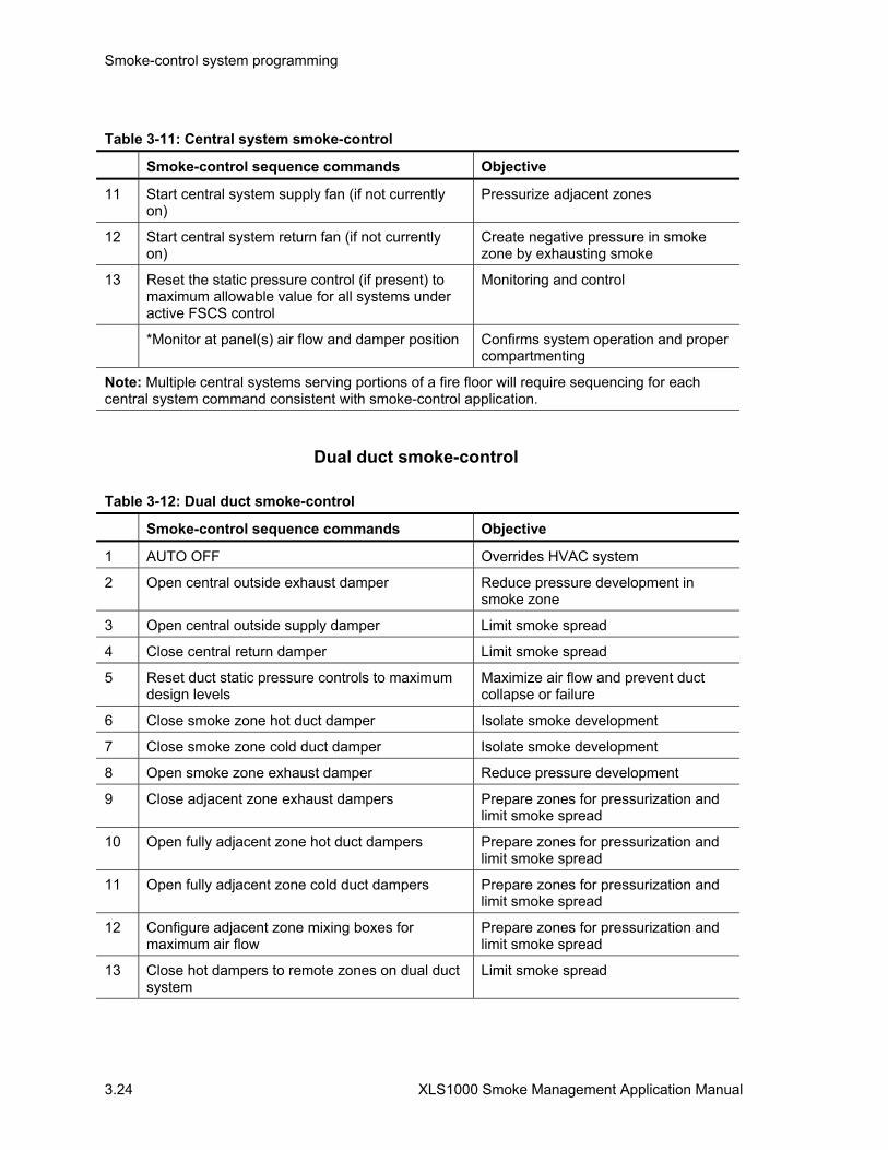
Smoke-control system programming
3.24 XLS1000 Smoke Management Application Manual
Table 3-11: Central system smoke-control
Smoke-control sequence commands Objective
11 Start central system supply fan (if not currently on)
Pressurize adjacent zones
12 Start central system return fan (if not currently on)
Create negative pressure in smoke zone by exhausting smoke
13 Reset the static pressure control (if present) to maximum allowable value for all systems under active FSCS control
Monitoring and control
*Monitor at panel(s) air flow and damper position Confirms system operation and proper compartmenting
Note: Multiple central systems serving portions of a fire floor will require sequencing for each central system command consistent with smoke-control application.
Dual duct smoke-control
Table 3-12: Dual duct smoke-control
Smoke-control sequence commands Objective
1 AUTO OFF Overrides HVAC system
2 Open central outside exhaust damper Reduce pressure development in smoke zone
3 Open central outside supply damper Limit smoke spread
4 Close central return damper Limit smoke spread
5 Reset duct static pressure controls to maximum design levels
Maximize air flow and prevent duct collapse or failure
6 Close smoke zone hot duct damper Isolate smoke development
7 Close smoke zone cold duct damper Isolate smoke development
8 Open smoke zone exhaust damper Reduce pressure development
9 Close adjacent zone exhaust dampers Prepare zones for pressurization and limit smoke spread
10 Open fully adjacent zone hot duct dampers Prepare zones for pressurization and limit smoke spread
11 Open fully adjacent zone cold duct dampers Prepare zones for pressurization and limit smoke spread
12 Configure adjacent zone mixing boxes for maximum air flow
Prepare zones for pressurization and limit smoke spread
13 Close hot dampers to remote zones on dual duct system
Limit smoke spread

Smoke-control system programming
XLS1000 Smoke Management Application Manual 3.25
Table 3-12: Dual duct smoke-control
Smoke-control sequence commands Objective
14 Close cold dampers to remote zones on dual duct system
Limit smoke spread
15 Close exhaust air dampers to remote zones on dual duct system
Limit smoke spread
16 Start central system supply fan (if not currently on)
Pressurize adjacent zones
17 Start central system return fan (if not currently on)
Create negative pressure in smoke zone by exhausting smoke
*Monitor at panel(s) air flow and damper position Confirms system operation and proper compartmenting
Note: Multiple dual duct systems serving portions of a fire floor will require sequencing for each dual duct system consistent with smoke-control application.
Exhaust to outside
SM
OK
E33
.CD
R
HEATINGCOIL
COOLINGCOIL MIXING
BOX
RECIRCULATIONAIR DUCT
Fan
Fan
Smoke zone 1 Smoke zone 2Smoke zone 4
MIXINGBOX
MIXINGBOX
Figure 3-3: Dual duct smoke-control
Dual duct smoke-control rules example Auto Limit SMKZONE 1 is an AND group which contains all initiating devices in smoke zone 1. The activation number =1 [Smoke Control SMKZONE1]
ALARM SMOKE ‘SMKZONE1’:

Smoke-control system programming
3.26 XLS1000 Smoke Management Application Manual
E DMP OPEN CENTRAL
OPEN ‘E_DMP_OP_CENTRAL’,
S DMP OPEN CENTRAL
OPEN ‘S_DMP_OP_CENTRAL’,
DISABLE OTHER SMKZONES
DISABLE ‘AND_SMKZONE2’,
DISABLE ‘AND_SMKZONE3’,
DISABLE ‘AND_SMKZONE4’,
DISABLE ‘AND_SMKZONE5’,
DLYA 30,
R DMP CLOSE CENTRAL
CLOSE ‘R_DMP_CLOSE_CENTRAL’,
Duct Pressure Control is set to Max Value
ON ‘DUCT_PRESSURE_CONTROL’,
H DMP CLOSE SMKZONE1
CLOSE ‘H_DMP_CLOSE_SMKZONE1’,
C DMP CLOSE SMKZONE1
CLOSE ‘C_DMP_CLOSE_SMKZONE1’,
E DMP OPEN SMKZONE1
OPEN ‘E DMP_OP_SMKZONE1’,
E DMP CLOSE
CLOSE ‘E_DMP_CLOSE_SMKZONE2’,
CLOSE ‘E_DMP_CLOSE_SMKZONE3’,
H DMP OPEN
OPEN ‘H_DMP_OP_SMKZONE2’,
OPEN ‘H_DMP_OP_SMKZONE3’,
C DMP OPEN
OPEN ‘C_DMP_OP_SMKZONE2’,
OPEN ‘C_DMP_OP-SMKZONE3’,
Configure SMKZONE2/3 Mixing Boxes(M) for Maximum Flow
OPEN ‘C_DMP_OP_SMKZONE2’,
OPEN ‘C_DMP_OP_SMKXONE3’,
OPEN ‘H_DMP_OP_SMKZONE2’,
OPEN ‘H_DMP_OP_SMKXONE3’,
H DMP OPEN REMOTE ZONES
OPEN ‘H DMP_OP_SMKZONE4’,
OPEN ‘H DMP_OP_SMKZONE5’,
C DMP OPEN REMOTE ZONES
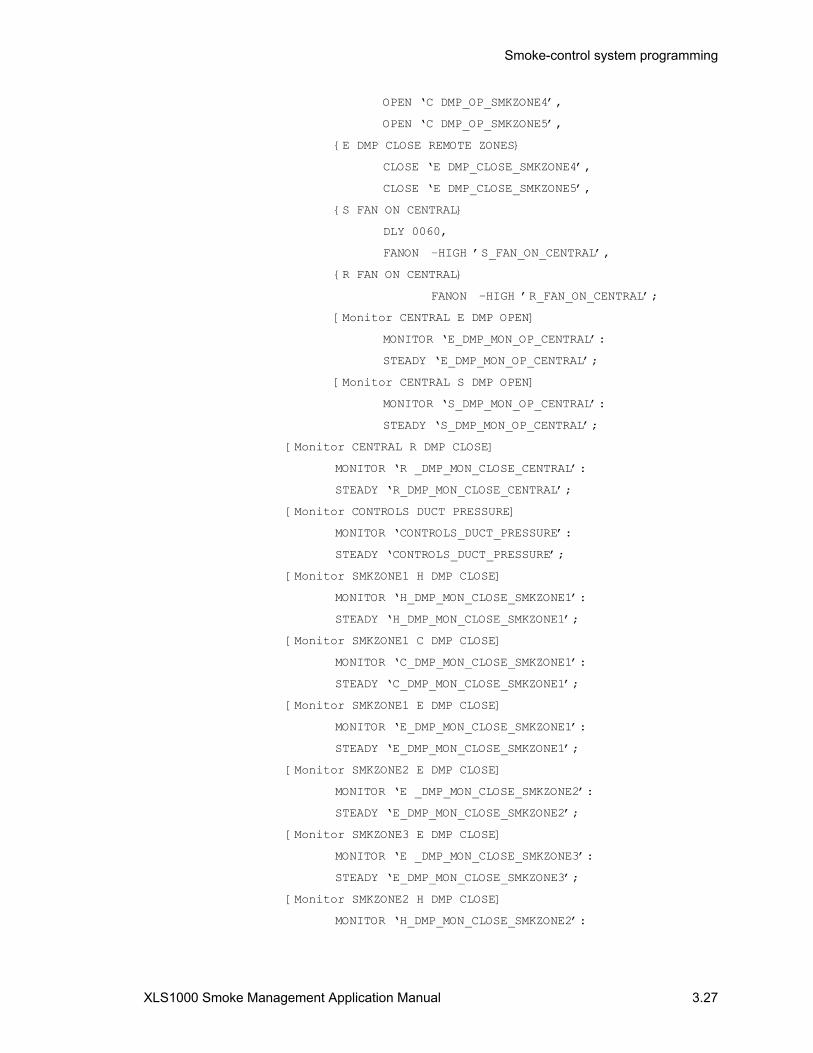
Smoke-control system programming
XLS1000 Smoke Management Application Manual 3.27
OPEN ‘C DMP_OP_SMKZONE4’,
OPEN ‘C DMP_OP_SMKZONE5’,
E DMP CLOSE REMOTE ZONES
CLOSE ‘E DMP_CLOSE_SMKZONE4’,
CLOSE ‘E DMP_CLOSE_SMKZONE5’,
S FAN ON CENTRAL
DLY 0060,
FANON –HIGH ’S_FAN_ON_CENTRAL’,
R FAN ON CENTRAL
FANON –HIGH ’R_FAN_ON_CENTRAL’;
[Monitor CENTRAL E DMP OPEN]
MONITOR ‘E_DMP_MON_OP_CENTRAL’:
STEADY ‘E_DMP_MON_OP_CENTRAL’;
[Monitor CENTRAL S DMP OPEN]
MONITOR ‘S_DMP_MON_OP_CENTRAL’:
STEADY ‘S_DMP_MON_OP_CENTRAL’;
[Monitor CENTRAL R DMP CLOSE]
MONITOR ‘R _DMP_MON_CLOSE_CENTRAL’:
STEADY ‘R_DMP_MON_CLOSE_CENTRAL’;
[Monitor CONTROLS DUCT PRESSURE]
MONITOR ‘CONTROLS_DUCT_PRESSURE’:
STEADY ‘CONTROLS_DUCT_PRESSURE’;
[Monitor SMKZONE1 H DMP CLOSE]
MONITOR ‘H_DMP_MON_CLOSE_SMKZONE1’:
STEADY ‘H_DMP_MON_CLOSE_SMKZONE1’;
[Monitor SMKZONE1 C DMP CLOSE]
MONITOR ‘C_DMP_MON_CLOSE_SMKZONE1’:
STEADY ‘C_DMP_MON_CLOSE_SMKZONE1’;
[Monitor SMKZONE1 E DMP CLOSE]
MONITOR ‘E_DMP_MON_CLOSE_SMKZONE1’:
STEADY ‘E_DMP_MON_CLOSE_SMKZONE1’;
[Monitor SMKZONE2 E DMP CLOSE]
MONITOR ‘E _DMP_MON_CLOSE_SMKZONE2’:
STEADY ‘E_DMP_MON_CLOSE_SMKZONE2’;
[Monitor SMKZONE3 E DMP CLOSE]
MONITOR ‘E _DMP_MON_CLOSE_SMKZONE3’:
STEADY ‘E_DMP_MON_CLOSE_SMKZONE3’;
[Monitor SMKZONE2 H DMP CLOSE]
MONITOR ‘H_DMP_MON_CLOSE_SMKZONE2’:
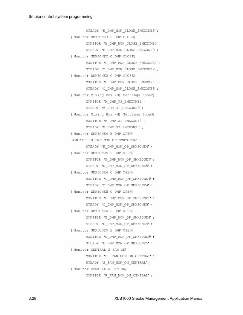
Smoke-control system programming
3.28 XLS1000 Smoke Management Application Manual
STEADY ‘H_DMP_MON_CLOSE_SMKZONE2’;
[Monitor SMKZONE3 H DMP CLOSE]
MONITOR ‘H_DMP_MON_CLOSE_SMKZONE3’:
STEADY ‘H_DMP_MON_CLOSE_SMKZONE3’;
[Monitor SMKZONE2 C DMP CLOSE]
MONITOR ‘C_DMP_MON_CLOSE_SMKZONE2’:
STEADY ‘C_DMP_MON_CLOSE_SMKZONE2’;
[Monitor SMKZONE3 C DMP CLOSE]
MONITOR ‘C_DMP_MON_CLOSE_SMKZONE3’:
STEADY ‘C_DMP_MON_CLOSE_SMKZONE3’;
[Monitor Mixing Box (M) Settings Zone2]
MONITOR ‘M_DMP_OP_SMKZONE2’:
STEADY ‘M_DMP_OP_SMKZONE2’;
[Monitor Mixing Box (M) Settings Zone3]
MONITOR ‘M_DMP_OP_SMKZONE3’:
STEADY ‘M_DMP_OP_SMKZONE3’;
[Monitor SMKZONE4 H DMP OPEN]
MONITOR ‘H_DMP_MON_OP_SMKZONE4’:
STEADY ‘H_DMP_MON_OP_SMKZONE4’;
[Monitor SMKZONE5 H DMP OPEN]
MONITOR ‘H_DMP_MON_OP_SMKZONE5’:
STEADY ‘H_DMP_MON_OP_SMKZONE5’;
[Monitor SMKZONE4 C DMP OPEN]
MONITOR ‘C_DMP_MON_OP_SMKZONE4’:
STEADY ‘C_DMP_MON_OP_SMKZONE4’;
[Monitor SMKZONE5 C DMP OPEN]
MONITOR ‘C_DMP_MON_OP_SMKZONE5’:
STEADY ‘C_DMP_MON_OP_SMKZONE5’;
[Monitor SMKZONE4 E DMP OPEN]
MONITOR ‘E_DMP_MON_OP_SMKZONE4’:
STEADY ‘E_DMP_MON_OP_SMKZONE4’;
[Monitor SMKZONE5 E DMP OPEN]
MONITOR ‘E_DMP_MON_OP_SMKZONE5’:
STEADY ‘E_DMP_MON_OP_SMKZONE5’;
[Monitor CENTRAL S FAN ON]
MONITOR ‘S _FAN_MON_ON_CENTRAL’:
STEADY ‘S_FAN_MON_ON_CENTRAL’;
[Monitor CENTRAL R FAN ON]
MONITOR ‘R_FAN_MON_ON_CENTRAL’:

Smoke-control system programming
XLS1000 Smoke Management Application Manual 3.29
STEADY ‘R_FAN_MON_ON_CENTRAL’;
Multi-zone smoke-control
Table 3-13: Multi-zone smoke-control
Smoke-control sequence commands Objective
1 AUTO OFF Overrides HVAC controls
2 Open central multi-zone outside exhaust outside dampers
Reduce pressure development in smoke zone
3 Close central multi-zone return damper Limit smoke spread
4 Reset duct static pressure controls to maximum design levels
Maximize air flow and prevent duct collapse or failure
5 Close smoke zone air supply damper Isolate smoke development
6 Open smoke zone air exhaust damper Reduce pressure development
7 Close adjacent zone exhaust dampers Prepare zones for pressurization and limit smoke spread
8 Open fully adjacent zone supply air dampers Prepare zones for pressurization and limit smoke spread
9 Close supply air dampers to remote zones on multi zone system
Limit smoke spread
10 Close exhaust air dampers to remote zones on multi zone system
Limit smoke spread
11 Start multi-zone system supply fan (if not currently on)
Pressurize adjacent zones
12 Start multi-zone system return fan (if not currently on)
Create negative pressure in smoke zone by exhausting smoke
*Monitor at panel(s) air flow and damper position Confirms system operation and proper compartmenting
Note: Multiple dual duct systems serving portions of a fire floor will require sequencing for each dual duct system consistent with smoke-control application.
VAV smoke-control
Table 3-14: VAV smoke-control
Smoke-control sequence commands Objective
AUTO OFF Overrides HVAC System
Open central VAV outside exhaust outside dampers
Reduce pressure development in smoke zone
Close central VAV return damper Limit smoke spread

Smoke-control system programming
3.30 XLS1000 Smoke Management Application Manual
Table 3-14: VAV smoke-control
Smoke-control sequence commands Objective
Reset duct static pressure controls to maximum design levels
Maximize air flow and prevent duct collapse or failure
Close smoke zone air supply damper Isolate smoke development
Open smoke zone air exhaust damper Reduce pressure development
Close adjacent zone exhaust dampers Prepare zones for pressurization and limit smoke spread
Open fully adjacent zone supply air dampers Prepare zones for pressurization and limit smoke spread
Close supply air dampers to remote zones on VAV system
Limit smoke spread
Close exhaust air dampers to remote zones on VAV system
Limit smoke spread
Start VAV system supply fan (if not currently on) and set for maximum allowable volume
Pressurize adjacent zones
Start VAV system return fan (if not currently on) and set for maximum allowable volume
Create negative pressure in smoke zone by exhausting smoke
Confirms system operation and shut-in
*Monitor at panel(s) air flow and damper position
Note: Multiple VAV systems serving portions of a fire floor will require sequencing for each VAV system consistent with smoke-control application.

XLS1000 Smoke Management Application Manual 4.1
Chapter 4 Smoke-control acceptance and testing
Summary
Initial smoke-control system turn on procedures and information concerning acceptance testing is provided in this chapter.
Content
Testing•4.2 Testing documentation•4.2
Smoke-control panel acceptance test procedure•4.3 Acceptance testing•4.4 Building component testing procedures•4.6 XLS1000 SCS/FSCS test procedures•4.6
XLS1000 SCS detection acceptance testing•4.13 Smoke-control input modules•4.15 Smoke-control output modules•4.16 Dedicated systems•4.17
Zoned smoke-control and atrium systems•4.17 Stairtower pressurization systems•4.18 Elevator shaft pressurization systems•4.19
Additional considerations•4.21 Other test methods•4.21 XLS1000 SCS owner’s manual and instructions•4.21 Partial occupancy•4.22 Modifications•4.22 Periodic testing•4.22

Smoke-control acceptance and testing
4.2 XLS1000 Smoke Management Application Manual
Testing Absence of a consensus agreement for a testing procedure and acceptance criteria for smoke control has historically created numerous problems at time of system acceptance, including delays in obtaining a certificate of occupancy.
The building owner, smoke-control system designer, and XLS1000 SCS designer/installer must agree upon the objective and design criteria for smoke-control with the authority having jurisdiction (AHJ)at the planning stage of the project to help ensure testing requirements are consistent with the systems original design. XLS1000 SCS design submittals for AHJ approval should include a procedure for acceptance testing in order that any programming or operational requirements set by the AHJ my be incorporated.
XLS1000 SCS contract documents should include operational and acceptance testing procedures so that system and smoke-control systems designers, installers, and the owner have an understanding of the system objectives and the testing procedure. The system designer, responsible for defining air flow rates, zones, and tenability will rely heavily upon the 3-DSDC to provide detection of fire and control of components which compartmentalize or vent smoke.
Testing documentation Upon completion of acceptance testing, a copy of all operational testing documentation should be provided to the owner and AHJ. This documentation should be available for reference in periodic testing and maintenance. For integrated systems, installed in compliance with NFPA 72, records of all testing and maintenance shall be kept on the protected premises for a period of at least five (5) years.

Smoke-control acceptance and testing
XLS1000 Smoke Management Application Manual 4.3
Smoke-control panel acceptance test procedure Once the system has been wired, programmed, and the circuit faults corrected, all installed components should be tested as a system, to ensure proper operation. Should additional problems be discovered, refer to the XLS1000 Installation and Service Manual for details on how to correct any problems uncovered. Since most XLS1000 SCSs will be integrated into an XLS1000 fire alarm network, testing and acceptance may also need to comply with the requirements of NFPA 72. Chapter 4 of the XLS1000 Installation Manual (P/N 95-7545) contains system power-up and testing procedures which should also be consulted. The FSCS, where installed, may also be integrated into the XLS1000 fire alarm network and tested under NFPA 72.
The initial system check is designed to verify that all components of the system are installed and operating as designed. Verifying that the system was designed and installed according to specifications requires all aspects of the system to be exercised and the results verified. Where test results differ from those expected, corrective action must be taken.
Before commencing testing, notify all areas where the alarm sounds and off premise locations that receive alarm and trouble transmissions, if any, that testing is in progress.
Testing of the smoke-control system will logically be performed as a part of the smoke-control air flow and compartmentation testing. While flow rates of fans may be the responsibility of others, their operation is contingent upon proper installation and programming of the XLS1000 SCS and FSCS. The test procedures reflect smoke control building component testing and smoke-control system and FSCS testing divided into three categories based upon NFPA 92A and NFPA 92B test procedures:
• Component testing • Acceptance testing • Periodic testing and maintenance
Building component testing: The intent of building component testing is to establish that the final smoke-control installation complies with the specified design, is functioning properly, and is ready for acceptance testing.
Prior to testing, the party responsible for this testing, normally the system designer, should verify completeness of building construction or compartmenting components including the following architectural features:
• Shaft integrity • Firestopping or glazing which may enclose a large space • Doors and closers related to smoke-control

Smoke-control acceptance and testing
4.4 XLS1000 Smoke Management Application Manual
• Partitions and ceilings
The operational testing of each individual building system component is performed to determine if smoke zones or areas are complete exclusive of XLS1000 SCS programmed commands. These operational tests normally will be performed by various trades before interconnection to the XLS1000 SCS is made.
It should be certified in writing by the responsible trades that each system component’s installation is complete and the component is functional including relays installed by others for interconnection to the XLS1000 SCS. Each component test should be individually documented, including such items as speed, voltage, and amperage.
Because smoke-control systems are usually an integral part of building operating systems, testing of the building system should include the following subsystems to the extent that they affect the operation of the smoke-control system:
• Energy management system • Building management and security system • HVAC equipment • Electrical equipment • Temperature control system • Power sources and standby power for fans and damper • Automatic suppression systems • Automatic operating doors and closures • Emergency elevator operation
In most applications building control components to the smoke-control system are required to operate from the building’s emergency power system as a backup to primary power. The electrical load required for motors in fan control circuits and status indicators from the emergency power must be provided for in emergency power design.
XLS1000 SCS/FSCS component testing: Components activated by the smoke-control system to be tested include:
• Dedicated smoke-control systems • Non-dedicated smoke-control systems • Fire alarm systems installed under NFPA 72
The FSCS series annunciator must receive power from other sources. The cabinet does not contain batteries for emergency power.
Acceptance testing The intent of acceptance testing is to demonstrate that the final integrated system installation complies with the specified design and is functioning properly. One or more of the following should be present to grant acceptance:

Smoke-control acceptance and testing
XLS1000 Smoke Management Application Manual 4.5
• Building system designer • XLS1000 SCS designer/installer • AHJ
All documentation from component testing should be available for inspection.
Building test equipment
The following equipment may be needed to determine air flows and compartmentation as a part of smoke-control acceptance testing:
• Differential pressure gauges, inclined water or electronic manometer
• Scale suitable for measuring door-opening force • Anemometer, including traversing equipment • ammeter • Flow-measuring hood (optional) • Door wedges • Tissue paper roll (for indicating direction of airflow) • Signs indicating a test of the smoke-control system is in
progress • Walkie-talkie radios for coordinating equipment
XLS1000 SCS test equipment
Required Tools:
• Slotted Screwdriver, Insulated • Digital Multimeter • 12 inch (30.5 cm) jumper lead with alligator clips • Panel Door Key
Building test parameters
The following parameters need to be measured during acceptance testing:
• Total volumetric flow rate • Airflow velocities and direction • Door-opening forces • Pressure differentials and ambient temperature
Smoke-control test parameters
The following parameters need to be confirmed during acceptance testing:
• XLS1000 SCS component control • XLS1000 SCS detection • FSCS override and component control

Smoke-control acceptance and testing
4.6 XLS1000 Smoke Management Application Manual
Building component testing procedures Prior to beginning acceptance testing, all building equipment should be placed in the normal operating mode, including equipment that is not used to implement smoke-control, such as toilet exhaust, elevator shaft vents, elevator machine room fans, and similar systems.
Wind speed, direction, and outside temperature should be recorded on each test day.
If standby power has been provided for the operation of the smoke-control system fans, louvers, or dampers, the acceptance testing should be conducted while on both normal and standby power. Disconnect the normal building power at the main service disconnect to simulate true operating conditions in this mode.
XLS1000 SCS/FSCS test procedures Smoke-control acceptance testing should include demonstrating that the correct outputs are produced for each input of a control sequence specified. Consideration should be given to the following control sequences, so that the complete smoke-control sequence is demonstrated:
• Normal mode • Automatic smoke-control mode for first alarm • Second alarm annunciation without automatic override of
first alarm • Manual override of normal and automatic smoke-control
modes • FSCS controls (where installed) override of all other system
controls • Return to normal
It is acceptable and desirable to perform acceptance tests for the fire alarm system in conjunction with the smoke-control system. One or more device circuits on the fire alarm system could initiate a single input signal to the smoke-control system. The smoke-control acceptance testing follows Chapter 4 of the XLS1000 Installation Manual.
A prepared smoke-control system testing procedure should be developed to establish the appropriate number of initiating devices and initiating device circuits to be operated to demonstrate the smoke-control system operation for the AHJ’s approval. The section titled Other test methods in this chapter contains additional information on test methods which may come under AHJ consideration for acceptance testing.

Smoke-control acceptance and testing
XLS1000 Smoke Management Application Manual 4.7
XLS1000 SCS/FSCS testing for smoke-control
Table 4-1: Initial acceptance testing for smoke-control equipment
Component Test procedure
Primary power supplies (required for XLS1000 SCS)
1. Verify that all components are installed in workman like manner.
2. Verify adequate separation between power limited and non-power limited wiring.
3. Verify that the installed batteries are the proper capacity for the application including the FSCS series annunciator, where installed.
4. With the batteries disconnected, verify that the supply’s full alarm load can be sustained by the power supply without the batteries connected. (Temporarily jumper the positive battery terminal to the positive auxiliary output to remove the battery trouble.)
5. With the batteries connected, disconnect the AC source and verify that a power supply trouble is annunciated, and that the supply’s full alarm load can be sustained by the batteries. The full alarm load may include the FSCS.
6. Verify that the battery charger properly charges the batteries connected to both the primary and booster power supplies to 80% capacity within 24 hours.
Table 4-2: Initial acceptance testing for smoke-control equipment
Component Test procedure
Booster power supplies 1. Verify that all components are installed in workman like manner.
2. Verify adequate separation between power limited and non-power limited wiring.
3. Verify that the installed batteries are the proper capacity for the application including the FSCS series annunciator, where installed.
4. With the batteries disconnected, verify that the supply’s full alarm load can be sustained by the power supply without the batteries connected. (Temporarily jumper the positive battery terminal to the positive auxiliary output to remove the battery trouble).
5. With the batteries connected, disconnect the AC source and verify that a power supply trouble is annunciated, and that the supply’s full alarm load can be sustained by the batteries. The full alarm load may include the FSCS.

Smoke-control acceptance and testing
4.8 XLS1000 Smoke Management Application Manual
Table 4-2: Initial acceptance testing for smoke-control equipment
Component Test procedure
3-CPU1 panel controller with 3-LCD display
1. Verify the module is properly seated in all four rail connectors and secured with the four snap rivets. Verify that removable terminal strips TB1 and TB2 are firmly seated.
2. Verify that all components are installed in workman like manner.
3. Verify that the correct date and time are displayed on the LCD display, and the Power LED is on.
4. Simultaneously press the Alarm, Silence, and Panel Silence switches to activate the lamp test function. Verify all LED’s on the graphic panel light.
5. Initiate an alarm and verify that: the Alarm LED flashes, the Alarm relay transfers, the correct device message appears at the top of the LCD window, the active point counter increments, the event sequence indicates a “1”, the active Alarm events counter at the bottom of the display indicates A001, the event type indicates fire alarm, and the local panel buzzer sounds. The graphic annunciator panel will have a panel alarm LED and zone LED. Press the Alarm queue switch and verify that the Alarm LED lights steady. Press the Panel Silence switch to verify that the panel buzzer silences and the Panel Silence LED lights. Press the Alarm Silence switch and verify that the required notification appliances are silenced. Press the Expanded Message Switch and verify that the alarm device’s expanded message, if any, is displayed. If a printer is connected to the 3-CPU1, verify that all specified information appears on the printer.
6. Initiate a second alarm in another smoke-control zone and verify that: it appears at the bottom of the LCD window, the active point counter changes, the event sequence indicates a “2”, the active Alarm events counter at the bottom of the display indicates A002, the event type indicates alarm, the Alarm LED re-flashes, the local panel buzzer re-sounds, and the first Alarm message remains at the top of the LCD display. Press the Alarm queue switch and verify that the Alarm LED lights steady.
7. Initiate a third alarm in a remaining area and verify that: its message appears at the bottom of the LCD window, the active point counter changes, the event sequence indicates a “3”, the active Alarm events counter at the bottom of the display indicates A003, the event type indicates alarm, and the local panel buzzer re-sounds, and the alarm message remains at the top of the LCD display. Press the Alarm queue switch and verify that the Alarm LED lights steady.
8. Use the previous and next message switches to verify that you can scroll through all three messages in the alarm queue, as indicated by the event sequence window.
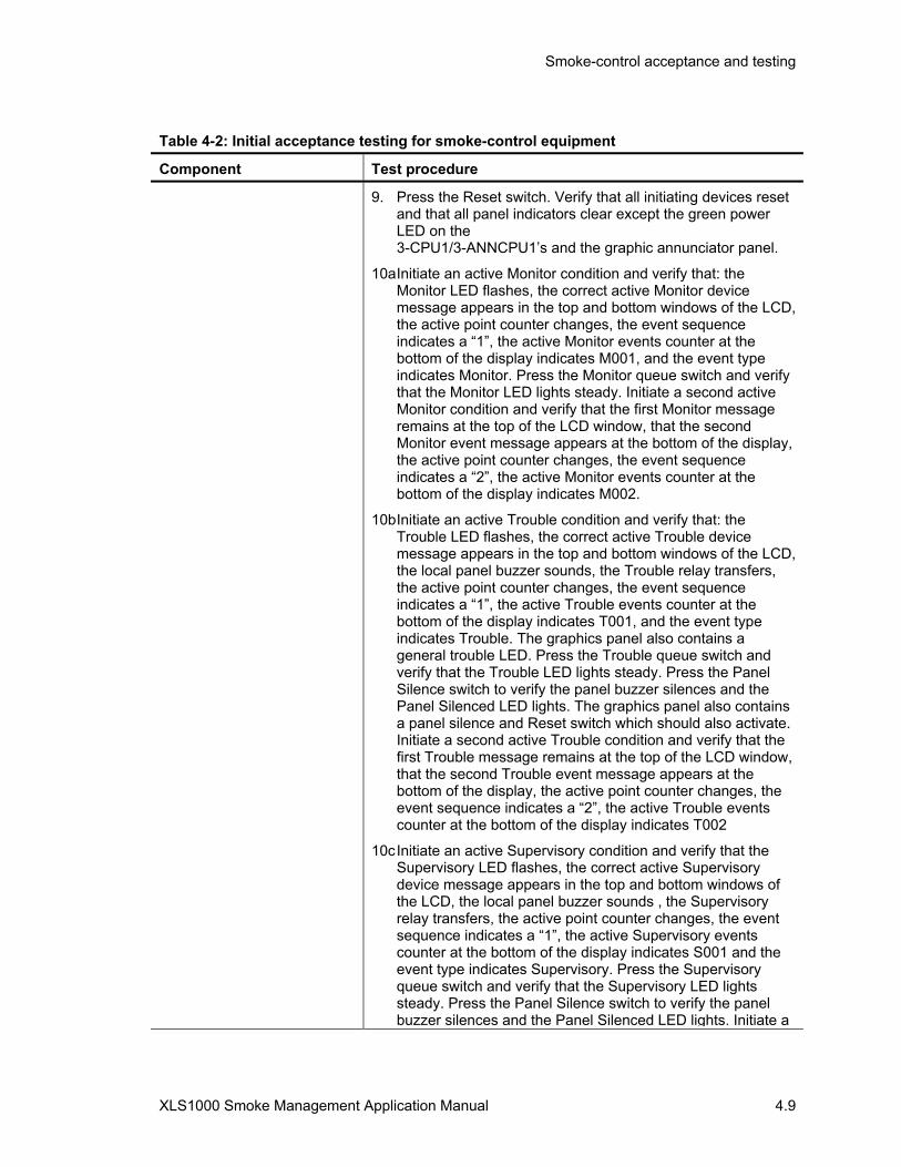
Smoke-control acceptance and testing
XLS1000 Smoke Management Application Manual 4.9
Table 4-2: Initial acceptance testing for smoke-control equipment
Component Test procedure
9. Press the Reset switch. Verify that all initiating devices reset and that all panel indicators clear except the green power LED on the 3-CPU1/3-ANNCPU1’s and the graphic annunciator panel.
10a Initiate an active Monitor condition and verify that: the Monitor LED flashes, the correct active Monitor device message appears in the top and bottom windows of the LCD, the active point counter changes, the event sequence indicates a “1”, the active Monitor events counter at the bottom of the display indicates M001, and the event type indicates Monitor. Press the Monitor queue switch and verify that the Monitor LED lights steady. Initiate a second active Monitor condition and verify that the first Monitor message remains at the top of the LCD window, that the second Monitor event message appears at the bottom of the display, the active point counter changes, the event sequence indicates a “2”, the active Monitor events counter at the bottom of the display indicates M002.
10b Initiate an active Trouble condition and verify that: the Trouble LED flashes, the correct active Trouble device message appears in the top and bottom windows of the LCD, the local panel buzzer sounds, the Trouble relay transfers, the active point counter changes, the event sequence indicates a “1”, the active Trouble events counter at the bottom of the display indicates T001, and the event type indicates Trouble. The graphics panel also contains a general trouble LED. Press the Trouble queue switch and verify that the Trouble LED lights steady. Press the Panel Silence switch to verify the panel buzzer silences and the Panel Silenced LED lights. The graphics panel also contains a panel silence and Reset switch which should also activate. Initiate a second active Trouble condition and verify that the first Trouble message remains at the top of the LCD window, that the second Trouble event message appears at the bottom of the display, the active point counter changes, the event sequence indicates a “2”, the active Trouble events counter at the bottom of the display indicates T002
10c Initiate an active Supervisory condition and verify that the Supervisory LED flashes, the correct active Supervisory device message appears in the top and bottom windows of the LCD, the local panel buzzer sounds , the Supervisory relay transfers, the active point counter changes, the event sequence indicates a “1”, the active Supervisory events counter at the bottom of the display indicates S001 and the event type indicates Supervisory. Press the Supervisory queue switch and verify that the Supervisory LED lights steady. Press the Panel Silence switch to verify the panel buzzer silences and the Panel Silenced LED lights. Initiate a

Smoke-control acceptance and testing
4.10 XLS1000 Smoke Management Application Manual
Table 4-2: Initial acceptance testing for smoke-control equipment
Component Test procedure second active Supervisory condition and verify that the first Supervisory message remains at the top of the LCD window, that the second Supervisory event message appears at the bottom of the display, the active point counter changes, the event sequence indicates a “2”, the active Supervisory events counter at the bottom of the display indicates S002.
10d. Initiate an active Alarm, verify that alarm LED flashes, the correct fire alarm/smoke-control message appears in the top and bottom windows of the LCD the active point counter changes, the event sequence indicates a “1”, the active alarm events counter at the bottom of the display indicates A001 and the event type indicates alarm. Press the Alarm queue switch and verify that the Alarm LED lights steady. Press the Panel Silence switch to verify the panel buzzer silences and the Panel Silenced LED lights. Initiate a second Alarm condition and verify that the first Alarm message remains at the top of the LCD window, that the second Alarm event message appears at the bottom of the display, the active point counter changes, the event sequence indicates a “2”, the active alarm events counter at the bottom of the display indicates A002.
11. LED’s for operation of smoke control components in 1-10 above are also contained on the graphic annunciator panel and must be confirmed for each device.
12. Press the Reset switch on the LCD or annunciator panel and verify that all devices reset and the panel returns to the normal condition.
3-RS232 card installed in 3-CPU1
1. Verify the card is properly seated in its connector and secured with the snap rivet.
2. Verify that the baud rate of the peripheral device connected to the port matches the port setting as set using the SDU program.
3. Check the printer (3-CPU1 only) operation by initiating an active condition on the system or generating a system report via the keypad.
3-RS485 card installed in 3-CPU1, class B configuration
1. Verify the card is properly seated in its connector and secured
2. For smoke control panels which are networked, start with the network in the normal condition and use the status command to verify all connected cabinets are communicating over the network.
3. Disconnect the network data communications wiring (TB2-17/18 & 19/20) from the cabinet with the primary 3-LCD Display, and verify that all the other system cabinets connected to the network appear in the trouble queue.

Smoke-control acceptance and testing
XLS1000 Smoke Management Application Manual 4.11
Table 4-2: Initial acceptance testing for smoke-control equipment
Component Test procedure
3-RS485 card installed in 3-CPU1, class A configuration
1. Verify the card is properly seated in its connector and secured with the snap rivet.
2. For smoke-control panels which are networked, start with the network in the normal condition and use the status command to verify all connected cabinets are communicating over the network.
3. Disconnect the network data communications wiring (TB2-17/18 & 19/20) from the cabinet with the primary 3-LCD Display, and verify that a Class A network data communications fault is annunciated. Repeat step 2 to verify that all connected cabinets are still communicating over the network.
3-IDC8/4 traditional I/O zone module for smoke-control
1. Familiarize yourself with the circuit configuration of the individual module to be tested. Remember, modules of the same type can be configured differently.
2. For circuits configured as Initiating Device Circuits (IDCs), activate the circuit by shorting the circuit’s two terminals. Verify that the appropriate message appears in the proper message queue. Disconnect the circuit or EOL resistor. Verify that a Trouble message appears in the Trouble message queue.
3. For circuits optionally configured as Notification Device Circuits (NACs), turn on the circuit by activating an IDC programmed to turn on the NAC, or use the activate output device command via the keypad. Verify that the circuit activates properly. Restore the circuit. Disconnect the circuit or EOL resistor. Verify that a Trouble message appears in the Trouble message queue.
3-DSDC Signature driver module
1. Verify that the module is properly seated in both rail connectors and secured with the two snap rivets. Verify that removable terminal strips TB1 and TB2 are firmly seated.
2. Verify the wiring to all Signature devices.
3. Map the SDC circuit by reading the device data; adjusting, modifying, and accepting devices as required; writing the information back to the devices; and re-reading the device data.
4. With no map errors displayed, put an input device on the circuit in the active mode, and verify the appropriate message is displayed on the 3-LCD Display and graphic annunciator, where installed. Put the input device in the Trouble mode and verify that the correct Trouble message is displayed.
NOTE :Individual device testing is detailed in other tables.

Smoke-control acceptance and testing
4.12 XLS1000 Smoke Management Application Manual
Table 4-2: Initial acceptance testing for smoke-control equipment
Component Test procedure
LED displays, XLS1000 SCS and Envoy FSCS series annunciator
1. Verify that the display(s) are properly seated in the module or graphic panel. Verify that the ribbon cable between the display and its host module is firmly seated on both ends.
2. For the FSCS perform a lamp test by pressing the Alarm Silence and Panel Silence switches simultaneously.
3. For the FSCS series annunciator there is a momentary pushbutton switch on the panel.
Control/LED Displays, XLS1000 SCS and Envoy FSCS series annunciator
1. Verify that the display(s) are properly seated in the module or graphic panel. Verify that the ribbon cable between the display and its host module is firmly seated on both ends.
2. Perform a lamp test by pressing the Alarm Silence and Panel Silence switches simultaneously. For the graphic annunciator panel there is a Lamp Test switch on the panel.
3. Perform a functional switch test.

Smoke-control acceptance and testing
XLS1000 Smoke Management Application Manual 4.13
XLS1000 SCS detection acceptance testing The procedures listed in Table 4-3, Table 4-5, and Table 4-7 should be performed on the detectors, input modules, output modules, and related accessories connected to each cabinet. Additional procedures for manual initiating devices may be found in Table 4-6. These procedures are presented to test the devices and smoke-control system programming.
Note: The network configuration, Signature Control module information must be downloaded into the network and Audio Source Unit, using the XLS1000 System Definition Utility (SDU) Program, before starting testing.
Every detector connected to the smoke-control system should be visited, and manually activated during the installation process to verify that:
1. The location meets design parameters for spacing and air flow.
2. The location annunciated by the smoke-control system agrees with the physical location of the device.
3. That the activated device initiates the correct smoke-control system response.
Table 4-3: Initial acceptance testing for detectors
Component Test procedure
Signature Series detectors and bases on a 3-SSDC module circuit
1. Verify that all components are installed in a workman like manner.
2. Individually activate each detector. Verify that the appropriate Alarm and location message is displayed on the 3-LCD display. Verify that the detector initiates the appropriate system responses. If the detector is installed in a relay base, verify that the base’s relay function operates correctly. If the detector is installed in an isolator base, verify that the base isolates the required circuit segments.
3. Duct mounted detectors should be tested to verify that minimum/maximum airflow requirements are met and that smoke-control actions or overrides are functioning.
4. Remove the detector from its base. Verify that the appropriate Trouble and location message is displayed on the 3-LCD display.
5. After all detectors have been individually inspected, run a Sensitivity report, using the Reports command.
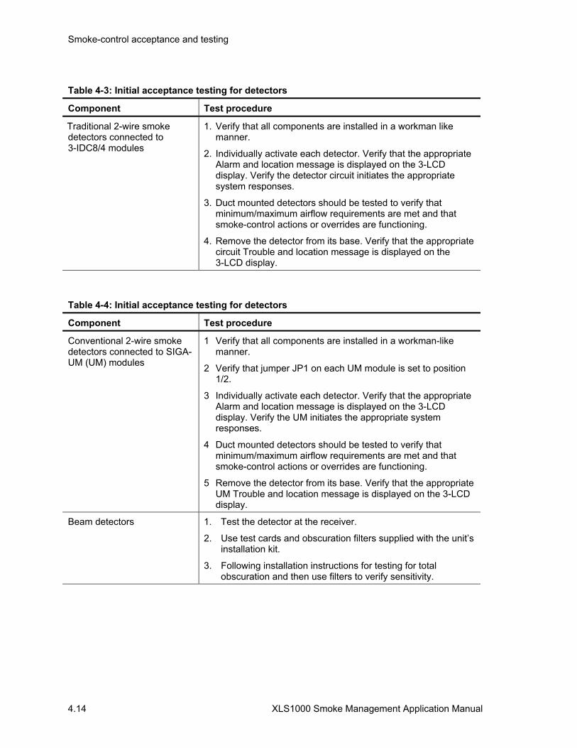
Smoke-control acceptance and testing
4.14 XLS1000 Smoke Management Application Manual
Table 4-3: Initial acceptance testing for detectors
Component Test procedure
Traditional 2-wire smoke detectors connected to 3-IDC8/4 modules
1. Verify that all components are installed in a workman like manner.
2. Individually activate each detector. Verify that the appropriate Alarm and location message is displayed on the 3-LCD display. Verify the detector circuit initiates the appropriate system responses.
3. Duct mounted detectors should be tested to verify that minimum/maximum airflow requirements are met and that smoke-control actions or overrides are functioning.
4. Remove the detector from its base. Verify that the appropriate circuit Trouble and location message is displayed on the 3-LCD display.
Table 4-4: Initial acceptance testing for detectors
Component Test procedure
Conventional 2-wire smoke detectors connected to SIGA-UM (UM) modules
1 Verify that all components are installed in a workman-like manner.
2 Verify that jumper JP1 on each UM module is set to position 1/2.
3 Individually activate each detector. Verify that the appropriate Alarm and location message is displayed on the 3-LCD display. Verify the UM initiates the appropriate system responses.
4 Duct mounted detectors should be tested to verify that minimum/maximum airflow requirements are met and that smoke-control actions or overrides are functioning.
5 Remove the detector from its base. Verify that the appropriate UM Trouble and location message is displayed on the 3-LCD display.
Beam detectors 1. Test the detector at the receiver.
2. Use test cards and obscuration filters supplied with the unit’s installation kit.
3. Following installation instructions for testing for total obscuration and then use filters to verify sensitivity.
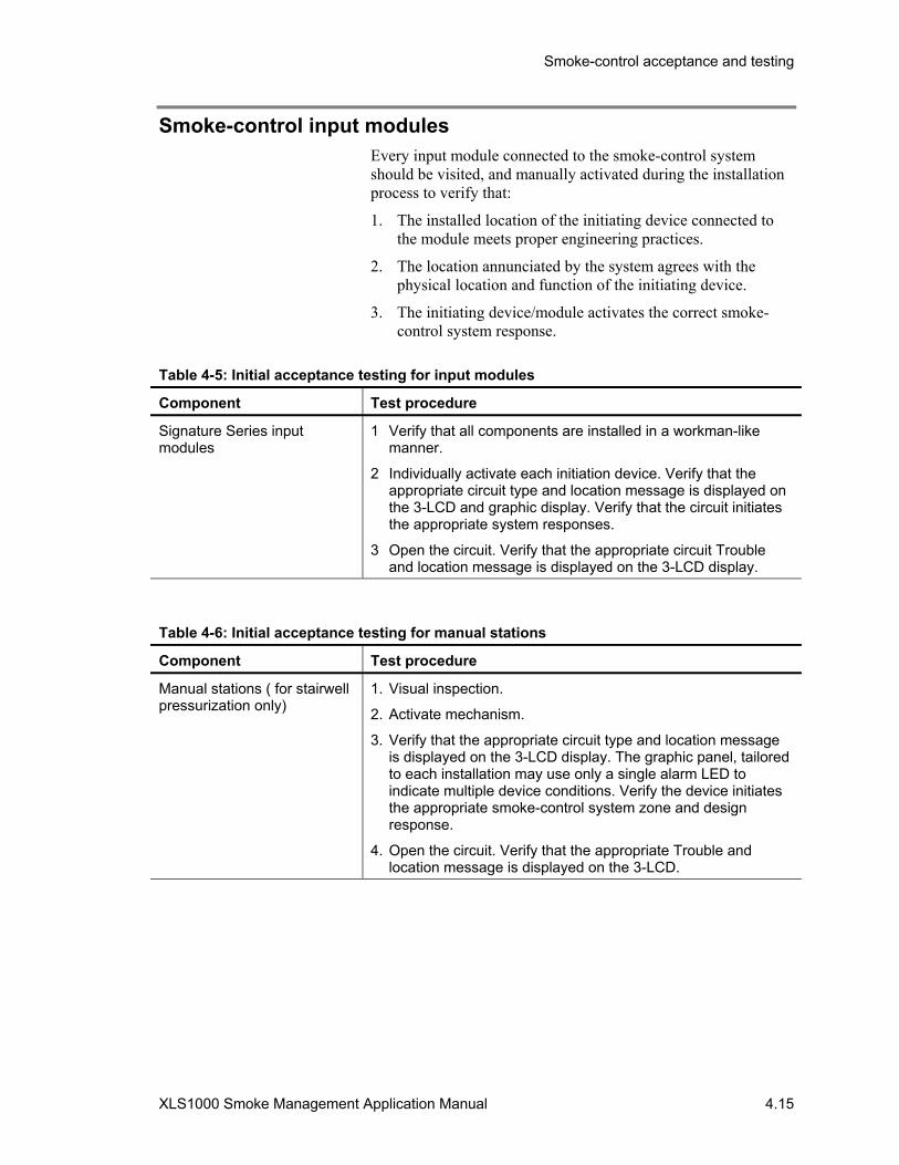
Smoke-control acceptance and testing
XLS1000 Smoke Management Application Manual 4.15
Smoke-control input modules Every input module connected to the smoke-control system should be visited, and manually activated during the installation process to verify that:
1. The installed location of the initiating device connected to the module meets proper engineering practices.
2. The location annunciated by the system agrees with the physical location and function of the initiating device.
3. The initiating device/module activates the correct smoke-control system response.
Table 4-5: Initial acceptance testing for input modules
Component Test procedure
Signature Series input modules
1 Verify that all components are installed in a workman-like manner.
2 Individually activate each initiation device. Verify that the appropriate circuit type and location message is displayed on the 3-LCD and graphic display. Verify that the circuit initiates the appropriate system responses.
3 Open the circuit. Verify that the appropriate circuit Trouble and location message is displayed on the 3-LCD display.
Table 4-6: Initial acceptance testing for manual stations
Component Test procedure
Manual stations ( for stairwell pressurization only)
1. Visual inspection.
2. Activate mechanism.
3. Verify that the appropriate circuit type and location message is displayed on the 3-LCD display. The graphic panel, tailored to each installation may use only a single alarm LED to indicate multiple device conditions. Verify the device initiates the appropriate smoke-control system zone and design response.
4. Open the circuit. Verify that the appropriate Trouble and location message is displayed on the 3-LCD.

Smoke-control acceptance and testing
4.16 XLS1000 Smoke Management Application Manual
Smoke-control output modules Every output module connected to the system should be visited, and manually activated during the installation process to verify that:
1. The installed location of the controlled device meets proper engineering practices.
2. The location of the controlled device annunciated by the system agrees with the physical location of the device.
3. The device is activated by the correct system input(s).
Table 4-7: Initial acceptance testing for output modules
Component Test procedure
Signature series output modules
1. Verify that all components are installed in a workman like manner.
2. Using the Activate Output command, individually activate each output. Verify that the device responds appropriately and the LED and graphic annunciator LED’s light.
3. For supervised output circuits, open up the circuit. Verify that the appropriate circuit Trouble and location message is displayed on the 3-LCD display.
4. If the output is activated by one or more system inputs, activate these inputs and verify the output priority function operates appropriately.
5. Confirm sequential operation for output modules connected to fans, dampers, and doors.
Table 4-8: Weekly testing of dedicated systems
Component Test procedure
Dedicated smoke control systems
1. Programming for the SCS must include a weekly test of dedicated systems and their components.
2. Results of automatic testing should verify that all components operate in the programmed sequence.
3. The program, at the designated time, must automatically activate the output command for each of the system inputs, verifying were necessary that dampers ( and other compartmenting components ) have opened or closed and fans have started or stopped.
4. A record of the automatic test sequences and results must be maintained at the location of the XLS1000 SCS.

Smoke-control acceptance and testing
XLS1000 Smoke Management Application Manual 4.17
Dedicated systems
Zoned smoke-control and atrium systems Verify the exact location of each smoke-control zone and the door or other openings in the perimeter of each zone. If the building plans do not specifically identify them, the smoke-control system may have to be activated in zones so that any magnetically held doors will close and identify smoke zone boundaries.
For the building components verification, the component designer should measure and record the pressure difference across all smoke-control zones that divide a floor. The measurements should be made while the HVAC systems serving the floor’s smoke zones are operating in their normal (i.e. non-smoke-control) mode. The measurements should be made while all smoke barrier doors that divide a floor into zones are closed. A measurement should be made across each smoke barrier door or set of doors, and the resulting data should clearly indicate the higher and lower pressure sides of the doors.
Using smoke-control input devices, verify the proper activation of each zoned smoke-control system in response to all means of activation, both automatic and manual, as specified in the contract documents. Where automatic activation is required in response to alarm signals received from the building’s smoke-control system, each separate alarm signal should be initiated to ensure that proper automatic activation of the correctly zoned smoke-control system occurs. Automatic weekly testing of dedicated systems should be cycled to verify all components operate as installed and programmed and that the test time is agreeable to the building owners. Verify confirming indications, documenting the proper operation of all fans, dampers, and related equipment for each separate smoke-control system zone.
Activate the zoned smoke-control system(s) that is appropriate for each separate smoke-control zone. Measure and record the pressure difference across all smoke barrier doors that separate the smoke zone from adjacent zones. The measurements should be made while all smoke barrier doors that separate the smoke zone from the other zones are fully closed. One measurement should be made across each smoke barrier door or set of doors, and the data should clearly indicate the higher and lower pressure sides of the doors. Doors that have a tendency to open slightly due to the pressure difference should have one pressure measurement made while held closed and another made when unrestrained.
Continue to activate each separate smoke-control zone and making pressure difference measurements. Ensure that after

Smoke-control acceptance and testing
4.18 XLS1000 Smoke Management Application Manual
testing a smoke zone it is properly deactivated and the HVAC systems involved return to their normal operating mode prior to activating another zone’s smoke-control system according to system programming. Also ensure that control verifying damper and fan operation necessary to prevent excessive pressure differences are functioning to prevent damage to ducts and related building equipment. Component testing should have previously verified operation of fans, dampers, doors, and other smoke-control equipment.
Stairtower pressurization systems The building system designer, with all building HVAC systems in normal operation, measure and record the pressure difference across each stairtower door while the door is closed. After recording the pressure difference across the door, measure the force necessary to open each door, using a spring-type scale. The building system designer should establish a consistent procedure for recording data throughout the entire test . The stairtower side of the doors will always be considered as the reference point and the floor side of the doors will always have the pressure difference value (positive if higher than the stairtower and negative when less than the stairtower). Since the stairtower pressurization system is intended to produce a positive pressure within the stairtower, all negative pressure values recorded on the floor side of the doors indicate a potential airflow into the floor.
The XLS1000 system designer, working with the building system designer, should verify the proper activation of the stairtower pressurization system(s) in response to all means of activation, both automatic and manual, as specified in the contract documents. Where automatic activation is required in response to alarm signals received from the building’s smoke-control system, each separate alarm signal should be initiated to ensure that proper automatic activation occurs. Automatic weekly testing of dedicated systems should be cycled to verify all components operate as installed and programmed and that the test time is agreeable to the building owners. Verify confirming indications, documenting the proper operation of all fans, dampers, and related equipment for each separate smoke-control system zone.
With the stairtower pressurization system activated, the building system designer should measure and record the pressure difference at points similar to those evaluated in zoned smoke-control and atrium systems.
After recording the pressure difference across each closed door, measure the force necessary to open each door. Use the established procedure to record data throughout the test. The

Smoke-control acceptance and testing
XLS1000 Smoke Management Application Manual 4.19
local code and contract documents should be followed regarding the door to be opened for this test.
With the stairtower pressurization system activated, open the doors required by the system design, one at a time, and measure and record the pressure difference across each remaining closed stairtower doors after the opening of each additional door. After recording the pressure difference across each closed door, measure the force necessary to open each door. Use the established procedure to record data throughout the test. The local code and contract document requirements should be followed regarding the number and location of doors that need to be opened for this test.
With the stairtower system activated, and all required doors open, determine and record the direction of airflow through each of the open doors. This can be done by using a small amount of smoke at the open doorway. If velocity measurements are required, a door opening traverse needs to be performed with the door fully open.
Stairwell pressurization systems typically have a smoke detector at the stair intake to stop fans should smoke begin to enter from the outside. There must be a manual override on the system to keep fans operating should a qualified emergency person determine that the smoke infiltration is minor. Testing of the override feature should be in the acceptance procedure.
Elevator shaft pressurization systems Shaft systems may incorporate exhausting of air from the fire floor, pressurization of elevator lobbies, pressurization of the elevator hoistway or by construction of smoketight elevator lobbies with pressurization. The type or combination of designs will dictate system operation and testing. Elevator recall and the use of elevators while the shaft or lobby is pressurized will be an integral part of the test procedure developed.
The piston effect due to car movement on elevator shaft pressurization has been researched and is discussed in several of the texts referenced in Chapter 1. There are no recommended tests to determine how shaft pressurization might be impacted with car movement. Elevator door testing currently assumes a median value for pressures developed against a door independent of car movement. No dynamic testing of the shaft pressurization system with car movement is therefore dictated.
The building system designer must define smoke-control sequences for design and testing and measure and record pressure differences in a manner similar to those described for stairwells.

Smoke-control acceptance and testing
4.20 XLS1000 Smoke Management Application Manual
Using smoke-control input devices, verify the proper activation of the shaft pressurization system in response to all means of activation, both automatic and manual, as specified in the contract documents. Where automatic activation is required in response to alarm signals received from the building smoke-control system, each separate alarm signal should be initiated to ensure that proper automatic activation occurs.
With the elevator shaft pressurization system activated, measure and record the pressure difference across each shaft or lobby door with all doors closed.
If an elevator door is held open due to recall, measure and record the pressure difference across each remaining closed door. Use an established procedure to record data throughout the entire test. The local code and contract documents should be followed regarding the elevator recall door to be opened or closed for this test.
With the elevator shaft system activated, determine and record the direction of airflow through each of the shaft or elevator lobby doors. This can be done by using a small amount of smoke at the doors.
Smoke-control acceptance and testing
XLS1000 Smoke Management Application Manual 4.21
Additional considerations
Other test methods The test methods presented in this chapter provide an adequate means to evaluate a smoke management system’s performance. Historically, other test methods have been used in instances where the authority having jurisdiction requires additional testing. These test methods have limited value in evaluating certain system performance, and their validity as a method of testing a smoke management system is questionable.
As covered in the Chapter 1 of this manual, the dynamics of the fire plume, buoyancy forces, and stratification are all major critical elements in the design of the smoke management system. Therefore, to test the system properly, a real fire condition would be the most appropriate and meaningful test. There are many valid reasons why such a fire is usually not practical in a completed building. Open flame or actual fire testing might be dangerous and should not normally be attempted. Any other test is a compromise. If a test of the smoke-control system for building acceptance is mandated by the authority having jurisdiction, such a test condition would become the basis of design and might not in any way simulate any real fire condition. More importantly, it could be a deception and provide a false sense of security that the smoke-control system would perform adequately in a real fire emergency.
Smoke bomb tests do NOT provide the heat, buoyancy, and entrainment of a real fire and are NOT useful in evaluating the real performance of the system. A system designed in accordance with this manual and capable of providing the intended smoke-control might not pass smoke bomb tests. Conversely, it is possible for a system that is incapable of providing the intended smoke-control to pass smoke bomb tests. Because of the impracticality of conducting real fire tests, the acceptance tests described in this manual are directed to those aspects of smoke management systems that can be verified and are consistent with current research and testing in the fire protection field.
Examples of other test methods that have been used with limited effectiveness are chemical smoke tests, tracer gas tests, and real fire tests.
XLS1000 SCS owner’s manual and instructions Information should be provided to the owner that defines the operation and maintenance of the smoke-control system. Basic instruction on the operation of the smoke-control system should be provided to the owner’s representatives. Since the owner may

Smoke-control acceptance and testing
4.22 XLS1000 Smoke Management Application Manual
assume beneficial use of the smoke-control system upon completion of acceptance testing, this basic instruction should be completed prior to acceptance testing and the owner’s representative who will have a maintenance responsibility should also be present.
Partial occupancy Acceptance testing should be performed as a single step when obtaining a certificate of occupancy. However, if the building is to be completed or occupied in stages, multiple acceptance tests may have to be conducted in order to obtain temporary certificates of occupancy.
Modifications All operational and acceptance tests should be performed on the applicable part of the system upon system changes and modifications. Documentation should be updated to reflect changes or modifications.
Periodic testing During the life of the building, maintenance is essential to ensure that the smoke-control system will perform its intended function under fire conditions. Proper maintenance of the system should, as a minimum, include the periodic testing of all smoke-control equipment including XLS1000 SCS controls, initiating devices, fans, dampers, controls, doors, and windows. The equipment should be maintained in accordance with the manufacturer’s recommendations. Refer to NFPA 90A, Standard for the Installation of Air Conditioning and Ventilating Systems, for suggested maintenance practices for non-dedicated HVAC and damper requirements. NFPA 92A, NFPA 92B, and NFPA 72 should be consulted for smoke-control panel testing.
These tests should be performed on a periodic basis to determine that the installed system continues to operate in accordance with the approved design.
The smoke-control system should be tested in accordance with the following schedule by persons who are thoroughly knowledgeable in the operation, testing, and maintenance of the systems. The results of the tests should be documented in the operations and maintenance log and made available for inspection.
Dedicated Systems
Weekly: Automatic testing every seven days of dedicated systems will cycle all components. Automatic tests must be recorded, with failure of any monitored components noted.
Smoke-control acceptance and testing
XLS1000 Smoke Management Application Manual 4.23
Semiannually: Operate the smoke-control system for each control sequence in the original design and observe the operation of the correct outputs for each given input. Tests should be conducted under standby power, if applicable.
Non-dedicated Systems
Annually: Operate the smoke-control system for each control sequence in the approved configuration and observe the operation of the correct output for each given input. Tests should be conducted under standby power, if applicable.
Special arrangements might have to be made for the introduction of large quantities of outside air into occupied areas or computer centers when outside temperature and humidity conditions are extreme. Since smoke-control systems override limit controls, such as freezestats, tests should be conducted when outside air conditions will not cause damage to equipment and systems.
Smoke-control acceptance and testing
4.24 XLS1000 Smoke Management Application Manual

XLS1000 Smoke Management Application Manual Y.1
Y Glossary
Automatic Control A system operating in this mode will initiate smoke-control measures without personnel intervention due to a fire detection system actuation.
Atrium A large-volume space created by a floor opening or series of floor openings connecting two or more stories that is covered at the top of the series of openings and is used for purposes other than an enclosed stairway, elevator hoistway, escalator opening, or utility shaft used for plumbing, electrical, air-conditioning, or communications facilities.
Buoyancy The ability or tendency of smoke to rise in air.
Communicating Space Spaces within a building that have an open pathway to a large-volume space such that smoke from a fire in the communicating space can move unimpeded into the large-volume space. Communicating spaces can open directly into the large-volume space or can connect through open passageways.
Compensated System A smoke-control system where the air injected into a stairwell is modulated or excess pressure is vented depending upon the number of doors opened or closed in the stairwell. This keeps the pressure barrier relatively constant.
Covered Mall A large-volume space created by a roofed-over common pedestrian area in a building enclosing a number of tenants and occupancies. Covered malls may include retail stores, drinking establishments, entertainment and amusement facilities, offices, or other similar uses where tenant spaces open onto or directly communicate with the pedestrian area.
Dedicated System A smoke-control system designed for the sole purpose of controlling smoke within a building. Equipment is not linked to the building HVAC system. This is accomplished by installing a system for air movement that is separate and distinct from the building's HVAC system and only operates to control smoke.
Firefighter's smoke-control station (FSCS)
Firefighter's smoke-control station (FSCS) includes monitoring and over-riding capability over smoke-control systems and equipment provided at designated location(s) within the building for the use of the fire department. Other firefighter's systems not required for smoke-control (voice alarm, public address, fire department communication, and elevator control and status) may be at the same location.
Large-Volume Space A space, generally two or more stories in height, within which smoke from a fire either in the space or in a communicating space can move or accumulate without restriction. Atriums and covered malls are examples of large-volume spaces.

Glossary
Y.2 XLS1000 Smoke Management Application Manual
Manual Control A smoke-control system operates in this state when controls for the station are changed manually to override automatic control functions.
Noncompensated System A smoke-control system in which a single speed fan provides pressurization in a stairwell. Pressure will vary depending upon the number of doors opened in the stairwell.
Non-dedicated System A smoke-control system that shares components with other air moving equipment. When the smoke-control mode is activated, the operating of the building's air moving equipment changes in order to accomplish the objectives of the smoke-control design.
Pressurized Stairwell A type of smoke-control system in which stair shafts are mechanically pressurized with outdoor air to keep smoke from contaminating them during a fire event.
Separated Spaces Spaces within a building that are isolated from large-volume spaces by smoke barriers that do not rely on airflow to restrict the movement of smoke.
Smoke The airborne solid and liquid particulates and gases evolved when a material undergoes pyrolysis or combustion, together with the quantity of air that is entrained or otherwise mixed into the mass.
Smoke Barrier A membrane, either vertical or horizontal, such as a wall, floor, or ceiling assembly, that is designed and constructed to restrict the movement of smoke. A smoke barrier might or might not have a fire resistance rating.
Smoke-Control Mode A predefined operational configuration of a system, zone, or device for the purpose of smoke-control.
Smoke-Control System(SCS) An engineered system that uses mechanical fans to produce airflow and pressure differences across smoke barriers to limit and direct smoke movement.
Smoke Damper A UL listed device designed to resist the passage of air or smoke. Smoke dampers are installed in ducts or smoke barriers separating floor or smoke zones. A fire barrier constructed to limit smoke may also serve as a smoke barrier and may use a combination fire and smoke damper that is also UL listed. Systems serving more than one floor with a capacity greater than 15,000 cfm are required by NFPA 90A to have smoke dampers installed to isolate the air handling equipment, including filters, to restrict the circulation of smoke.
Smoke Exhaust System A mechanical or gravity system intended to move smoke from a smoke zone to the exterior of a building, including smoke removal, purging, and venting systems, as well as the function of exhaust fans utilized to reduce the pressure in a smoke zone.
Smoke Management System An engineered system that includes all methods that can be used singly or in combination to modify smoke movement in a building.

Glossary
XLS1000 Smoke Management Application Manual Y.3
Smoke Proof Enclosure A continuous stairway which is enclosed from top to bottom by a 2-hour firewall and exits to the exterior of a building. Entry into the stairway must be through vestibules or outside balconies on each floor. The design must limit smoke entry and include ventilation which is natural or mechanical.
Smoke Zone The smoke-control zone in which the fire is located.
Stack Effect The vertical airflow within buildings caused by the temperature-created density differences between the building interior and exterior or between two interior spaces.
Tenable Environment An environment in which smoke and heat is limited or otherwise restricted in order to maintain the impact on occupants to a level that is not life threatening. In a zoned smoke-control system, pressure differences are used to maintain a tenable environment in an area intended to protect building occupants while evacuation is taking place.
Zoned Smoke-Control A smoke-control system that includes smoke exhaust for the smoke zone and pressurization for all contiguous smoke-control zones. The remaining smoke-control zones in the building also may be pressurized.