Embed Size (px)
Citation preview

J' . .
GPO PRICE $
CFSTI PRICE(S) $
Microfiche (M F) - 75 ff 653 July 65
I I. 1 ,
https://ntrs.nasa.gov/search.jsp?R=19660008729 2019-02-03T02:12:04+00:00Z

I ' . t-1
NOTICE
This report was prepared as an account of Government sponsored work. Neither the the United States, nor the National Aeronautics and Space Administration (NASA), nor any person acting on behalf of NASA:
Makes any warranty or representation, expressed nr !m$:!:ed, with respect to the ~ ~ ~ ~ r z c y , compieteness , or ueefulnese of the information contained in this report, o r that the use of any information, apparatus, method, o r process disclosed in this report may not infringe privately owned rights; O t
Assumes any liabilities with respect to the use of, o r for damages resulting from the use of any information, apparatus, method o r process disclosed in this report.
/
A s ueed above, "person acting on behalf of NASA" inclu&d'any employee o r con- tractor of NASA, or employee of such contractor, to the'extent that such employee o r contractor of NASA, or employee of such contractor prepares, disseminates, o r provides access to, any information pursuant to his employment o r contract with NASA, o r his employment with such contractor.
II
Requests for copies of this report should be referred to I
rl National Aeronautics and Space Administration Office of Scientific and Technical Information
Washington, D.C. 20546
I Attention: AFSS-A 1
I '
.

NASA CR-54137 BAC 60009-509
SUMMARY REPORT
DEVELOPMENT OF A MINIATURE ELECTROSTATIC ACCELEROMETER (MESA) FOR LOW g APPLICATIONS
M.A. Meldrum, E.J. Harrison, and Z. Milburn
prepared for
NATIONAL AERONAUTICS AND SPACE ADMINISTRATION
April 30, 1965
CONTRACT NAS 3-4102
- .l'ecnnicai ivianagement NASA Lewis Research Center
Cleveland, Ohio Spacecraft Technology Division
Bernard L. Sater
BELL AEROSYSTEMS COMPANY P.O. Box 1
Buffalo 5, New York

DEVELOPMENT OF A MINIATURE ELECTROSTATIC ACCELEROMETER (MESA) FOR LOW g APPLICATIONS
M. A. Meldrum, E. J. Harrison, and Z. Milburn
ABSTRACT
A miniature, single-degree-of-freedom digital electrostatic accelerometer -3 -12
to 10 (MESA) has been developed for measurement of accelerations in the 10
range. The design, fabrication, and qualification test results of the MESA are
discussed in this Summary Report.
g
ii

I
I
DEVELOPMENT OF A MINIATURE ELECTROSTATIC ACCELEROMETER (MESA) FOR LOW g APPLICATIONS
by
M. A. Meldrum, E. J. Harrison, and Z. Milburn
SUMMARY
Under the sponsorship of the NASA Lewis Research Center, Spacecraft
Technology Division, a Miniature Electrostatic Accelerometer (MESA) has been
developed by Bell Aerosystems Company Products and Instruments Group.
The program, initiated in August, 1963, had as its objective the development
of a digital accelerometer capable of accurately measuring accelerations in the
10 to 10 g range. The accelerometer was required to withstand, without
degradation in performance, high launch vibration and shock conditions of the Thor-
Delta vehicle, and to operate reliably over long periods of time in an orbiting en-
vironment. To achieve those objectives, two miniaturized versions of the digital
Electrostatic Accelerometer (ESA) developed under A i r Force Contract AF33(616) - 6637 were designed, fabricated, and tested.
-3 -6
Although the evaluation of accelerometer performance in the low g range is
limited in part by the requirement that laboratory tests must be conducted in a 1 g
environment, significant performance data was obtained. Test results showed:
-7 -3 (1)
(2)
(3)
(4)
Long term scale factor variation of less than 3 x 10
Scale factor temperature coefficient of 7 x I O - ~ ~ / O F for 10 -7
Long term null variations of less than *5 x 10
Null temperature coefficient of less than 3 x 10
g for 10 g input. -3
g input.
g for l g suspension. -6 g/g/"F for 1.g suspension.
The MESA also demonstrated that it is capable of sustaining (without perfor-
mance degradation) 40 g peak acceleration and 15 g shock.
iii

I
This program has enabled the accurate measurement of very low acceler-
ations to be made by an accelerometer also capable of withstanding a wide range of
high g launch environments. It has also established that the variable range electro-
static suspension and digital constrainment concept is one which offers a practical
solution to accurate low g measurements.
The major task remaining is the evaluation of the MESA performance -6 -12
to 10 characteristics in a low g (10
could be accomplished in an orbital experiment. A successful evaluation would
enable the MESA to be used in an even greater variety of spacecraft guidance and
control applications where accelerations of 10
Typical of these applications are:
g) rather than1 g test environment; this
-6 -12 to 10 g range a re encountered.
Spacecraft gravity gradient attitude stabilization and control.
Spacecraft orbital alignment and compassing.
Measurement of orbital parameters such as eccentricity, true anomaly and semi-major axis.
Spacecraft drag and thrust measurement for synchronous orbit station- keeping.
Measurement of gravity of the earth, moon, and planets.
Interplanetary trajectory velocity control.
iv

CONTENTS
Section Page
1 . 0 INTRODUCTION . . . . . . . . . . . . . . . . . . . . . . . . . . . . . . . . 2.0 TECHNICAL DESCRIPTION .........................
2.1 Description of the Basic Instrument . . . . . . . . . . . . . . 2.2 Theory of Operation ......................... 2.2.1 Suspension System . . . . . . . . . . . . . . . . . . . . . . . . . . 2.2.2 Suspension of a Cylinder ...................... 2.2.3 Sensitive Axis Restrainment . . . . . . . . . . . . . . . . . . . 2.2.4 Analysis of Float Motion . . . . . . . . . . . . . . . . . . . . . . 2.2.5 General Principle of Pickoff System . . . . . . . . . . . . . .
3 . 0 ME CHANICA L DE SIGN ............................ 3.1 Accelerometer ............................ 3.1.1 Float . . . . . . . . . . . . . . . . . . . . . . . . . . . . . . . . . . . 3.1.2 Electrode Carrier . . . . . . . . . . . . . . . . . . . . . . . . . . 3.1.3 Forcer Block . . . . . . . . . . . . . . . . . . . . . . . . . . . . . 3.1.4 Bonnet and Inductor Terminal Boards . . . . . . . . . . . . . 3.1.5 Housing . . . . . . . . . . . . . . . . . . . . . . . . . . . . . . . . . 3.2 Electronics Assembly ....................... 3.1.6 The Accelerometer Assembly . . . . . . . . . . . . . . . . . .
4.0 ELECTRICAL DESIGN . . . . . . . . . . . . . . . . . . . . . . . . . . . . 4.1 Suspension System . . . . . . . . . . . . . . . . . . . . . . . . . . 4.1.1 Suspension Oscillator . . . . . . . . . . . . . . . . . . . . . . . . 4.1.2 Suspension Amplifier . . . . . . . . . . . . . . . . . . . . . . . .
Capacitive Bridge and Buffer (Bonnet Electronics) . . . . . 4.2.3 Preampiifier~~emr?~uiai;or .................... 4.2.4 D-C Amplifier ............................. 4.2.5 4.2.6 Phase. Amplitude and Quadrature Networks . . . . . . . . . 4.3 Pulse Generation System ..................... 4.3.1 f Trigger Circuit .......................... 4.3.2 Multivibrators . . . . . . . . . . . . . . . . . . . . . . . . . . . . 4.3.3 Pulse Generators .......................... 4.3.4 Core Temperature Control .................... 4.4 Miscellaneous Electronics .................... 4.4.1 Temperature Controls . . . . . . . . . . . . . . . . . . . . . . . 4.4.2 Power Supply ............................. 4.4.3 Precision Regulator ........................
4.2 Pickoff System . . . . . . . . . . . . . . . . . . . . . . . . . . . . 4.2.1 4.2.2 1.1 mc Filter .............................
192 kc Reference Oscillator ....................
1
3 3 6 6 9 10 12 17
19 19 19 19 20 21 21 21 22
23 23 23 24 24 24 26 26 26 26 26 27 27 27 29 29 29 29 30 30

CONTENTS (CONT)
Section Page
5.0 SYSTEMTEST . . . . . . . . . . . . . . . . . . . . . . . . . . . . . . . . . 5.1 Null . . . . . . . . . . . . . . . . . . . . . . . . . . . . . . . . . . . 5.1.2 Long Term Null Stability . . . . . . . . . . . . . . . . . . . . . 5.1.3 Null Temperature Sensitivity . . . . . . . . . . . . . . . . . . . 5.2 Scale Factor .............................. 5.2.1 Channel Balance . . . . . . . . . . . . . . . . . . . . . . . . . . . 5.2.2 Long Term Scale Factor Stability . . . . . . . . . . . . . . . . 5.2.3 5.2.4 Scale Factor Linearity . . . . . . . . . . . . . . . . . . . . . . . 5.3 Shock and Vibration Tests ..................... 5.4 Error Analysis ............................ 5.4.1 Scale Factor Stability ........................ 5.4.2
Scale Factor Temperature Sensitivity . . . . . . . . . . . . .
Null and Null Stability . . . . . . . . . . . . . . . . . . . . . . . . 5.4.3 Scale Factor Linearity . . . . . . . . . . . . . . . . . . . . . . .
6.0 CONCLUSIONS AND RECOMMENDATION . . . . . . . . . . . . . . . 6.1 Low g Testing . . . . . . . . . . . . . . . . . . . . . . . . . . . . . 6.2 Mechanical Design . . . . . . . . . . . . . . . . . . . . . . . . . . 6.3 Electronic Design ..........................
7.0 DESIGN REVIEW ................................ 7.1 System Test Data . . . . . . . . . . . . . . . . . . . . . . . . . . 7.2 Failures . . . . . . . . . . . . . . . . . . . . . . . . . . . . . . . . 7 . 3 System Operation . . . . . . . . . . . . . . . . . . . . . . . . . . 7.4 Summary . . . . . . . . . . . . . . . . . . . . . . . . . . . . . . . .
31 31 31 32 32 32 33 33 33 34 34 34 34 35
46 46 46 47
48 48 48 49 49
vi

ILLUSTRATIONS
Figure Page
1 2 3 4 5 6 7 8 9 10 11 12 13 14 15 16 17 18 19
MESA IA System ................................. Primary Mechanical Elements . . . . . . . . . . . . . . . . . . . . . . . . Single-Degree-of -Freedom Suspension System . . . . . . . . . . . . . Equivalent Force Diagram of Suspension System . . . . . . . . . . . . Restrainment System .............................. Float Motion . . . . . . . . . . . . . . . . . . . . . . . . . . . . . . . . . . . . Pickoff System . . . . . . . . . . . . . . . . . . . . . . . . . . . . . . . . . . Pickoff System . . . . . . . . . . . . . . . . . . . . . . . . . . . . . . . . . . Pulse Generation System . . . . . . . . . . . . . . . . . . . . . . . . . . . Null Stability; SN 101 Before Environmental Tests . . . . . . . . . . Scale Factor Stability; SN 101 Before Environmental Tests . . . . Scale Factor Stability; SN 101 Before Environmental Tests . . . . Null Stability; SN 102 Before Environmental Tests . . . . . . . . . . . Scale Factor Stability; SN 102 Before Environmental Tests . . . . . Scale Factor Stability; SN 102 Before Environmental Tests . . . . . Null Stability; SN 101 After Environmental Tests . . . . . . . . . . . Scale Factor Stability; SN 101 After Environmental Tests . . . . . . Scale Factor Stability; SN 101 After Environmental Tests . . . . . . Shock Vibration Requirements for Miniaturized Accelerometers
When Launched by Thor-Delta Vehicle . . . . . . . . . . . . . . . . .
4 5 8 11 13 14 18 25 28 36 37 38 39 40 41 42 43 44
45
v ii
.

SECTION 1.0
INTRODUCTION
The requirement for an accelerometer capable of measuring accelerations in
the to
Accelerometers of this type would find extensive use in orbital guidance and control
of spacecraft where the accurate measurement of low g levels would be required.
A conventional force balance accelerometer such as the Bell Model IIIB could not be
used in this application because of limited null stability and repeatability. This
limitation is due to the cross-coupling of the mechanical suspension forces into the
instrument sensitive axis. The accelerometer mechanical suspension system must
also be capable of withstanding the maximum cross-axis g under launch conditions
(up to 100 g). However, in a low g environment, little suspension force is required.
Since it is not possible to easily change the mechanical suspension force, a con-
ventional instrument is limited to measurements in the 10
g range was recognized by Bell Aerosystems Company in 1959.
-5 to 100 g range.
To overcome this problem, Bell Aerosystems undertook a program to develop
an accelerometer whose acceleration sensing proof mass was suspended and con-
strained by electrostatic forces whose magnitude could be changed to meet the
operating g environment by a simple change in suspension and constrainment voltage
levels. Under the sponsorship of the Guidance Division, Ai r Force Avionics
Laboratory, Research and Technology Division, A i r Force Systems Command , Wright
Patterson A i r Force Base, Ohio, a development program was initiated in 1959 and
completed in 1963 under contract AF33(616) -6637. The feasibility of the electro-
static accelerometer concept was demonstrated and four experimental models tested.
The ESA developed had the following characteristics:
(1) Single-degree -of -f reedom.
(2)
(3)
Acceleration sensing proof mass was suspended and constrained by electrostatic forces.
Sensitive axis constrainment was achieved by pulse force rebalance techniques.
1
I
(4) Instrument g scaling was adjustable by simple change in signal level.
(5) Output was a digital pulse rate proportional to acceleration.
(6) Accelerometer was capable of withstanding high g loads without performance degradation,
Under sponsorship of the NASA Lewis Research Center, a program (details
of which a re presented in this report) was undertaken to develop two flight qualified
miniature versions of the electrostatic accelerometer (MESA) for measurement of
accelerations in the 10 to 1 0 g range, Significant improvements and refine-
ments were made in both electronic and mechanical design. The accelerometer
size was reduced by half without compromising performance. The electronics for
the power supply, pickoff and pulse constrainment system, suspension system, and
temperature controls were designed and fabricated as welded modules and tested.
The MESA system was successfully tested under typical launch and simulated
orbital environments.
-4 -6
The remaining sections in this report discuss the theoretical experimental
and practical aspects of the MESA program. Conclusions and recommendations are
given at the end of the report.
2
SECTION 2.0
TECHNICAL DESCRIPTION
The basic design philosophy of the MESA assumes a dynamic range of (the
ratio of minimum measurable input to maximum measurable input) as representative
of the state-of-the-art. Today, the low g range requirement does not in itself require
immediate advance in the state-of-the-art, provided the dynamic range remains the
same. Therefore, an instrument with a range of, for example, 10-l' to 10
within the state-of-the-art.
-5 g is
The minimum measurable acceleration is the function of the coupling of the sus-
pension system into the sensitive axis. To lower the minimum measurable acceleration,
the suspension system must be weakened. This can be accomplished easily in an
electrostatic suspension system by reducing the suspension voltage. The basic con-
cept is to use an electrostatic system which wi l l permit adjustment and calibration in
the one g field of the earth and to switch the suspension voltage to a lower value for
measuring in-space acceleration environments.
2.1 DESCRIPTION OF THE BASIC INSTRUMENT (Figures 1 and 2)
The proof mass is a hollow cylindrical float which has a flange around the center.
The cylinder is supported by eight electrodes arranged to act against the inner surface
of the float. Each electrode is in series with a tuning inductor which exerts a voltage
across the electrode-float gap which is a function of the float position. The float
-nn:+;n- am+---:--- +I.- . - - n n - ; k r in o anr ina tlrnnd oirmlit and therpfnre the owrating pvuruuii u ~ ~ c ~ i i i i i i c m ulc b a p a b l b y L I X CL V U L I U Y ----, ---_----_ - , ----,
point on the series resonance characteristic curve. A s a result of this situation, an
attractive force develops between the float and electrode which increases as the float
moves away from the electrode, causing the float to be suspended in all directions
except along the cylindrical axis. The suspension system therefore centers the float
under angular and translational accelerations. The suspension sweep oscillator and
amplifiers provide automatic suspension of the float without voltage breakdown o r
arcing.
3

4

5

I
Detection of the float movement is accomplished by sensing the change in capacity
between the pickoff ring concentric with the float flange. When used in a balanced
capacitive bridge circuit excited by a carrier frequency, displacement of the float results
in a signal output from the bridge. This output is amplified and phase sensitive demo-
dulated to produce a d-c voltage whose polarity is a function of the direction of the float
movement and whose amplitude is a measure of the relative displacement of the ac-
celerometer null position. This voltage, when applied to the trigger circuit, results in
the generation of d-c pulses which restrain the float. The d-c level at which pulsing
starts is called the trigger level.
The forcing of the float along the sensitive (cylindrical) axis is accomplished by
rings which form a capacity to the float flange. Voltage pulses are applied to these
rings in a similar manner to force along the sensitive cylindrical axis. The pulses are
generated by a pulse core which controls the amplitude and width of the pulse. This
pulse generation technique is presently used on digital velocity meters for the Agena
program and its accuracy and stability have been verified in many space flights. The
system output information is a pulse rate proportional to acceleration.
2.2 THEORY OF OPERATION
2.2.1 Suspension System
The basic principle for suspending the accelerometer utilizes the force
between the charges from the plates of the capacitor. The attractive force tends to
move the plates toward each other. This electrostatic force is given by the equation
dynes * K V ~ A F = 8 T s 2 9
where K = Dielectric constant (assumed to be unity)
V is the voltage across the plate (volts) 2 A is the area of the plates (cm )
8 is the gap between the plates (cm)
*Edgcumbe, K., and Ockender, F .E .J., ffIndustrial Electrical Measuring Instruments,f* Sir Isaac Pitman and Sons Ltd., London, 1933, pg. 207.
6

If the equation is expanded, the force per unit area can be written
dynes 2 cm
2 F -7 A - = 4.42 x 10
With fixed voltages on the capacitor plates, the attractive force increases
as 6 decreases which is not the action needed for the suspension system. To over-
come this effect, constrainment is effected using an a-c voltage applied to a resonant
circuit consisting of an inductance in series with the capacitance. The voltage across
the gap will vary as the gap changes, decreasing as the gap decreases if the operating
frequency f is slightly above the resonant frequency f . 0
Consider the single-degree-of-freedom suspension system shown in
Figure 3 . The resonant frequency corresponds to the value for a centralized float.
The following equations are derived.
The voltage across each gap can be shown to be
L 2 2
E (1 + u\
[l - (f/f,, 2 + u ‘ 1 2 +[212 ‘
centralized gap capacity (farads) c = -
L = tuning inductance (henry)
KA where
0 8
1 I f = /Tr resonant frequency 0 2?Td y”o
R = series resistance (ohms)
E = suspension excitation (volts)
normalized float displacement x - u = - - 6
Vcl =
Vc2 =
voltage across electrode 1
voltage across electrode 2
7
2 volts (3)

I 2 1
I
I dl Electrode No. 1 ,
Float
I - 8 -
*- L -
+ E - I 1 1 e
Electrw’j.: 1’.1. 2
L -7 I I
R R
Force Attracting Float To Electrode No. 1
= N e t Force on Float F 1- -- 1
-x <-- (B) F lo+ D ispl.cer??,e Et F2
Force Attracting Float To Electrode No. 2 \
Figure 3. Single-Degree-of-Freedom Suspension System
a

2 2 2 volts 2 E (1 - U)
vc2 = 2 f/f 2 [ 1 - (f/fOl2 - u] + [e] (4)
This derivation is based on the float being at ground potential. The net
force acting in a direction to restore the float to its equilibrium position is given by
FN = Kf [( F)2 - (+f ] dynes
where =
d2 =
8 - x = 8 (1 - u) = gap between electrode 1 and float (cm)
8 + x = 8 (1 + u) = gap between electrode 2 and float (cm) dl
Substituting (3) and (4) in (5) 1
If the operating frequency f is selected such that
1 f = f (1 + - )
2Q0 0
Equation (6) reduces to
2.2.2 Suspension of a Cylinder
3 F Q u
0 0
4 (QoU)
1+ - 4
dynes
A flanged cylindrical proof mass and an eight electrode suspension system
has the following properties. The suspension forces are normal to the instrument
sensitive axis. Restraint is provided against both translation and rotation in the two
transverse axes. The eight electrode configuration makes use of a balanced
9
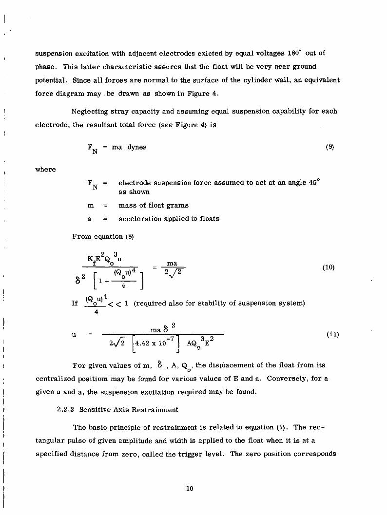
suspension excitation with adjacent electrodes exicted by equal voltages 180' out of
phase. This latter characteristic assures that the float will be very near ground
potential. Since all forces are normal to the surface of the cylinder wall, an equivalent
force diagram may be drawn as shown i n Figure 4.
I
I
I
Neglecting stray capacity and assuming equal suspension capability for each
electrode, the resultant total force (see Figure 4) is ,
FN = ma dynes
where
FN =
m = mass of float grams
a = acceleration applied to floats
electrode suspension force assumed to act at an angle 45' as shown
From equation (8)
1 ma
2P 4
If (Qou) < < 1 (required also for stability of suspension system) 4
2 J 2 (4.42 x lo - ' I AQ -EY L J 0
For given values of m y 6 , A , Q , the displacement of the float from its 0
centralized positiom may be found for various values of E and a. Conversely, for a
given u and a, the suspension excitation required may be found.
2.2.3 Sensitive Axis Restrainment
The basic principle of restrainment is related to equation (1). The rec-
tangular pulse of given amplitude and width is applied to the float when it is at a
specified distance from zero, called the trigger level. The zero position corresponds
10

F N = F - F F N = F - F
N3 N2 N4 N1
t ma
AreaA 2 cm L Float
M a s s m
ma
f i F N ma h F N
Figure 4. Equivalent Force Diagram of Suspension System
11

to a position of the float equidistant between the pickoff and/or forcer rings on either
side of the float. Positive and negative pulses of equal amplitude and width are applied
simultaneously to two forcer rings on the forcer block. They maintain the float at o r
near ground potential while attracting it in a direction opposite to that of the applied
acceleration. With reference to Figure 5, the restoring force actingon the float is
given by
Defining
where
Fp = Kf [( F) + (?I] dynes
dl = 8 , + X f = 8 , (1 +u$, then
K, = 4.42 x IO-' A 2 Af = forcer ring area cm
XF normalized float displacement (uf < < 1)
Uf =e= 8 = f gap between forcer ring and flange on float when it is at its
zero position
2.2.4 Analysis of Float Motion (Figure 6)
Consider a float with mass r tmrc under a total applied acceleration 5. The
acceleration of the float is given by
.. - x = a -
where x = - a =
a = t = a =
P =
distance from an arbitrary zero position (cm) 2 total acceleration acting on the float (cm/sec )
2 acceleration to be measured (cm/ft ) -1 damping constant (sec )
2 equivalent pulse acceleration (cm/sec )
differentiation with respect to time
12

Pulse Transformer
/
I E - P
Forcer Ring 1 AreaAf cm2
d
I Forcer Ring
4 4 1
0
Float Flange I.
Figure 5. Restrainment System
13

Parabolic
/
I 3 4
T
Maximum Swing Above % X Trigger Level t
T + T 1 + T 3 P
Maximum Swing Below Xt
I
0 A T I 1
I
- a = Total Acceleration Acting on Float
Figure 6. Float Motion
14

Equation (14) is integrated to find the velocity
where (to) = time when x (t) = 0, a = a
= start of pulse
t = length of pulse P
= the time between the end of the pulse and the point where the float reaches its maximum excursion below the trigger level t3
Ry writing the expressions for (t) at each of the various times and setting
x (t + t + t ) = 0, it can be shown that l P 3
[ ctPaP 1 - ll
a e a - 1 a
- - - € t l e
P [ C t P e
This equation determines the time required to reach the trigger level from the
maximum excursion of the float. Equation (15) is integrated to give the general dis-
tance formula.
The equation of motion of the float may be written
nnj; + %x = ma - F P
K where c =m = damping constant = 2000 dynes/cm/sec (approx.)
F = force due to pulse P
m = float mass = 0.72 gm
(i8)
15

Substituting equation (13) for F P'
Integrating equation (19),
Assume
1.
2. a is constant
Motion is periodic with period T.
tP 2 t
3. 1 E 2 ( t ) d t = I E dt = E t P P P 0
P 0
Pulse is rectangular with width T P
where
x = trigger level distance T X(T)= x(0) x(Tj = x(0j
aT = a t P P
where
2 a = P
16

1 a f = - = - T a t
P P CPS
Equation (24) expresses the basic principle upon which the digital accel-
erometer is based. The frequency of the float motion is proportional to acceleration,
the number of pulses proportional to velocity. The proportionality constant is a t . P P
Its stability and magnitude determine the scale factor stability and magnitude.
2.2.5 General Principle of Pickoff System (Figure 7)
The two pickoff rings form arms of a bridge which is balanced when the
float is equidistant between each ring. This distance is referred to as the pickoff
gap width 8 amplitude modulated by the float movement. The bridge output at AB is amplified
and then phase sensitive demodulated to provide a d-c signal proportional to the
float position.
The bridge is excited by an a-c excitation voltage E which is P' C
It may be shown that the output of the transformer when it is tuned to the
excitation frequency fo is
V 0 w o C C ~ R ~ U D /900 - = c + C M
C E
where
u = normalized float displacement
CM = C = bridge arm capacity
0 0 0
RL' =
P pickoff centraiized float capacity
= 27Tf
transformer tuned impedance in parallel with the load R on the transformer L
1 Given f , E , RL , C , and u the required pickoff capacity CM may be
o c P determined for a given V .
0
17

t
t
0
Ring
Tuned Transformer
Figure 7. Pickoff System
18

SECTION 3.0
MECHANICAL DESIGN
I ~ 3.1 ACCELEROMETER
3.1.1 Float
One of the most difficult problems encountered in the accelerometer de-
l sign was fabrication of the thin-walled beryllium float to very fine dimensional
tolerances. Beryllium was used for its high strength-to-weight ratio and its good
dimensional stability with temperature change. Cylinder straightness and roundness
and flange flatness, parallelism and perpendicularity to the cylinder are rigidly con-
trolled since they limit the cross-axis coupling coefficient of the instrument. Typical
dimension are as follows (dimensions in inches) :
I
Flange width 0.0150 f 0.0005 1
Cylinder thickness
Flange O.D.
Cylinder I. D.
Cylinder length
Cylinder straightness and roundness
Flange squareness to cylinder diameter
Surface finishes
Weight
0.0050 f 0.0002
1.282 f 0.001
0.4991 f 0.0002
0.864 f 0.001
< 10 x 10-6
< 0.0001 2 to 10 x rms
0.72 gram
3.1.2 Electrode Carrier
The electrode carr ier requirements impose relatively complex fabrication
problems. The eight electrodes must be electrically conductive but well insulated
from all others, and have a hard, smooth surface finish with no sharp corners o r
discontinuities. The assembly is fabricated with polished stainless steel electrodes
embedded in 'high strength, low thermal coefficient, low dissipation, high resistivity
19

I epoxy resin. Its O.D., electrode area, and surface finish are closely controlled to
ensure good symmetry and force balance in the suspension system electric field.
I The carrier dimensions, in inches, are: I O.D. 0.496500 f 0.000050
The forcer block is an important element of the accelerometer design
since it contains the pickoff and constrainment electrodes. It must have the same
electrical properties as the electrode carrier including low stray capacity and high
dimensional stability. Three concentric, equal area, stainless steel rings are
embedded in epoxy resin. The inner and outer rings a re forcer rings, energized by
equal amplitude, opposite polarity constrainment pulses. They exert equal attractive
forces on the float flange while inducing zero net charge on the float. The center
I Length 1.220 nominal
I Electrode length 0.339 f 0,001
Straightness and roundness < 10 x
Surface finish < 4 x rms
O.D. 1.9300 f 0.0001
Width 0.5917 f 0.0005
I.D. 0.496300 f 0.000050
Electrode rings Flat within 5 x TIR
Surface of rings 10 x 10-6 TIR
Roundness of O.D. and I.D. < 50 x TIR
Perpendicular to O.D. within
20

3.1.4 Bonnet and Inductor Terminal Boards I
I The pickoff bridge output is transformer coupled to an emitter follower
stage for isolation from and impedance matching to the electronics interconnecting
cable. The components a re mounted on a terminal board at the connector end of the
accelerometer (called the bonnet) within the housing. I
The suspension electrodes (on the electrode carrier) and the float cylinder
form the capacitors of the series tuned LC suspension circuits. The associated
adjustable inductors and current limiting resistors a re mounted on two terminal
boards in sets of four "behind" each forcer block.
3.1.5 Housing
The aluminum housing, in conjunction with the forcer blocks and electrode I
I ~
I
carrier, determines the alignment between the float flange and the pickoff and forcer
sensitive axis alignment, All critical surfaces a re polished to less than 10 micro-
inches r m s and parallelism and perpendicularity, where applicable, a r e maintained
to 0.001 inch TIR.
O-ring seals to the center section.
rings. The housing also establishes the accelerometer mounting surface and hence, I
,
I The assembled housing consists of top and bottom caps with
3.1.6 The Accelerometer Assembly
Critical surfaces, including the exterior surface of the housing, are plated
with an amorphous nickel-phosphorus coating (approximately 0.0003 in. thick) to
provide solderable surfaces o r to preclude aluminum to aluminum pressure fits.
The uncoated surfaces were polished (where required) then the plating applied with
negligible degradation of finish.
The O-ring sealed assembly is helium leak tested prior to the final f i l l
with dry nitrogen at 1.0 atmosphere. The leak rate is verified to be less than 10
cc/sec. It is estimated that only 16% of the entrapped nitrogen would be lost per
year at this average leak rate in a space environment.
-8
2 1

I The accelerometer is held at a constant operating temperature (approxi-
mately 35OC) by a wrap-around heater element in a thermistor-sensor temperature
control loop. The stability of the internal temperature is better than f 0.loC over
the anticipated operating range of 25 *5OC. Thermal isolation from its mounting
surface is achieved by use of a mounting ring of dense, rigid ceramoplastic material
with excellent dimensional stability and very high dielectric strength (called Mykroy) .
~
I
I 3.2 ELECTRONICS ASSEMBLY
I
I
The electronics package contains all the subsystems for power conditioning,
output signal generation and suspension, constrainment, and pickoff electronics.
The subsystems are constructed of welded o r soldered cordwood modules fastened
to fiberglass "mother" boards. Selected components for circuit adjustment and
I
trimming are mounted on these boards. Intercircuit wiring is arranged to allow easy
I access to all circuits by folding top boards out to reach lower level circuits. All I
suspension and pickoff circuit screwdriver adjustments are available by removing
the main cover only. The pulse generation circuits and their associated vernier
temperature controllers are placed in an oven occupying one end of the assembly.
I
I
The package is attached to its mounting base by five pads to ensure structural 1
rigidity while minimizing heat transfer to the environment.
22
SECTION 4.0
E LECTRICAI, DESIGN
1
4.1 STJSPENSION SYSTEM
The eight (.imt:d xrcwit;; fi-hic;h make up the accelerometer suspension are
supplied by a balanced a-c voltage from a transformer-coupled amplifier. Balancing
is achieved by a potentiometer.-c~prt@itor combination at the amplifier output to
adjust the sum of the susperrsiorr lirLe currents to zero. The system is designed for
automatic suspension of the proof mass without arcing or voltage breakdown. The
suspension voltage amplitude is adjustable and determined by the accelerometer
cross-axis g load.
4.1.1 Suspension Oscillator
The suspension oscillator provides a variable frequency signal which
sweeps smoothly from approximately 1.4 to 1.100 mcps in approximately five
seconds to produce float liftoff and suspension. By changing the excitation frequency
in this manner, the voltage gradient across the electrode-float gap builds up gradu-
ally and minimizes the possibility of voltage breakdown. Noninstantaneous operating
frequency change is necessary s l so to maintain a stable relationship between the
individual tuned circuit resonant frequency shifts (produced by the respective elec-
trode-float capacity changes during liftoff) and the excitation frequency. Float
inertia and damping ljmit the minimum stable sweep time to approximately 0.5
second.
The c;sc;i!?atsr is a cc?r,.:.-ntinnal k.ncid collector LC oscillator with voltage
variable capacitors in the ttmk circuit whi1:h produce a frequency change propor-
tional to an impressed d--c voltage. When at the REST(f1oat not suspended) frequency,
24 vdc is applied to the CONTROL terminal to produce an excitation frequency of
approximately 1.4 mcsps. To start the sweepdown, the 24 vdc is removed. The
voltage across the varicap diodes decreases along an exponential curve established
by an RC timing network resulting in a decreasing oscillator frequency. When the
2 3

. operating frequency of 1,100 mcps is reached, a regulator circuit consisting of a
1.100 mcps crystal and a voltage doubler causes the sweep action to cease. A
portion of the oscillator output voltage is coupled to the voltage doubler through the
crystal. The doubler output is added to the decaying varicap voltage through a diode.
When the sweeping frequency reaches the crystal resonant frequency, the doubler
output rises sharply (due to crystal Q) to the varicap voltage necessary to maintain
the crystal resonant frequency. This is called the FLOAT (suspended) frequency.
Resetting to the REST frequency may be done instantaneously without damage to the
float.
4.1.2 Suspension Amplifier
The suspension amplifier is a wideband feedback type which amplifies the
sweep oscillator output. The amplifier output is transformer-coupled to the eight
tuned circuits along two output lines which are balanced to ground; amplitude-wise
by a potentiometer across them with its a r m grounded, and phase-wise by a selected
fixed capacitor to balance line capacity to ground. The nominal closed loop gain is
15 with stability of 1%. Its output impedance is less than 20 ohms to assure high tuned
circuit Q. The output level is adjustable by a potentiometer at its input.
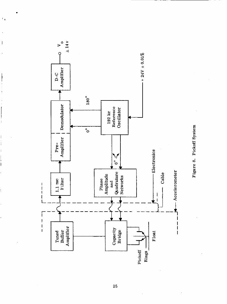
4.2 PICKOFF SYSTEM
The pickoff system (Figure 8) is the amplitude-modulated suppressed-carrier
type. Float movement along its sensitive axis produces an amplitude-modulated 192
kc signal at the bridge output. This signal is filtered, amplified and phase de-
modulated. The result is a d-c signal whose amplitude is a measure of float dis-
placement and whose polarity indicates direction of motion. Typical pickoff loop
gain is 60,000 v/cm at the demodulator output.
4.2.1 Capacitive Bridge and Buffer (Bonnet Electronics)
The fixed a rms of the capacitive pickoff bridge are stable ceramic
capacitors, the differential arms a re the €loat-ring combination. The bridge output
signal is coupled through a double shielded transformer to an emitter-follower
buffer stage. A degree of filtering is obtained by tuning the transformer secondary to the car r ie r frequency, 192 kc.
24
I -4
25

,
4.2.2 1.1 mc Filter
The "bonnet" output signal passes through a 1.1 mc trap which suppresses
unwanted pickup from suspension system wiring by 30 db.
4.2.3 Preamplifier/Demodulator
The preamplifier section of this module provides an a-c gain of 50 at 192
kcps. It is a feedback amplifier with transformer coupled output to the demodulator
section and has gain stability of 1.5%. The demodulator is a full-wave bridge recti-
fier type deriving its reference voltage from the 192 kc reference oscillator.
4.2.4 D-C Amplifier
The d-c amplifier is a conventional design with its closed-loop gain
adjusted to approximately 30. Cascaded differential amplifiers are used in the first
two stages (feeding a single-ended output stage) to obtain good thermal stability
without exotic compensation. At its input are a 384 kc trap to suppress the de-
modulator output ripple and a 30 kc rolloff network to attenuate high frequency noise.
Its output voltage range is zero to *14 vdc.
4.2.5 192 kc Reference Oscillator
The reference oscillator is a crystal controlled Colpitts type circuit. The
output is regulated by a Zener diode limiter, followed by the tuned output transformer.
Two isolated output windings supply the reference voltage to the demodulator section
of the preamplifier/demod and the accelerometer bridge excitation voltage through
the phase, amplitude and quadrature networks.
4.2.6 Phase Amplitude and Quadrature Networks
A high resolution, low resistance potentiometer between the upper fixed
bridge capacitors allows equalization of impedances between the two sides of the
bridge, thereby minimizing quadrature content in the bridge output signal. An RC
constant amplitude phase shift network across the reference oscillator centertapped
winding is used to compensate for phase shifts between the demodulator input and
.
26

r reference voltages to minimize the magnitude of carrier signal in the d-c null. A
potentiometer at the phase shifter output allows optimum adjustment of pickoff loop
gain by controlling the bridge excitation voltage. Each of these adjustments is
easily accessible on terminal boards.
I
4.3 PULSE GENERATION SYSTEM
I
One of the most critical performance parameters is the stability of the forcer
pulse size. The method of generation and control of pulses is to switch a saturable
core transformer between its two saturated states while maintaining its magnetic
parameters constant by extremely tight temperature control of its tape wound core
and good regulation of its supply voltage. The MESA system (Figure 9) employs
two identical channels each feeding a set of accelerometer forcer rings.
4.3.1 *Trigger Circuit
The f trigger circuit is a dual channel level sensor set to deliver a turn-on
signal to the positive pulse generator when its input voltage reaches +7 volts and to
the negative generator for -7 volt input. The actuating signal remains until the float
motion input voltage has been reduced below the respective trigger level by the
forcer pulses thus applied. The turn-on signals a re produced when the float motion
voltage exceeds the conduction levels of oppositely oriented Zener diodes (approxi-
mately 7 volt types).
4.3.2 Multivibrators
Identical multivibrators a re used in the (+) and (-) channels. They con-
sist of a latching stage, which is "unlatched" by the proper turn-on signal from the
* trigger; followed by a free-running multivibrator adjusted to a free-running rate
of 5 kcps; and a flip-flop triggered from the multivibrator to control the core
switching transistors.
The latching stage receives a "hold" or set signal from the multivibrator
to prevent relatching during a pulse interval. Therefore, the circuit gates only
integral numbers of pulses to the forcer rings. The minimum pulse spacing (200
27

I t -
i
i
n
28

t microseconds) is also established by the free-running multivibrator to prevent the
pulses from running too close together. Digital output pulses are also generated
by this circuit,
4.3.3 Pulse Generators
The pulse transformer, a saturable tape-wound core type, has a center-
tapped primary which is switched alternately by transistors driven by the multi-
vibrator. The secondary is tapped for approximately 300, 10, and 3 volts (peak) for
1, 10 and 10 g constrainment, respectively. Nominal pulsewidth is 160 micro-
seconds. The primary supply voltage is nominally 24 vdc, regulated to 0.02% or
better through a *20 ppm/O C limiting resistor to maintain stable magnetization
current ,
-3 -4
4.3.4 Core Temperature Control
The stability of the pulse generator is determined by several factors, one
being the temperature variation of the magnetic tape in the pulse transformer. To
control the tape temperature to *0.05°C with changes in external ambient and internal
power dissipatim, the resistance of the tape is sensed in a d-c bridge circuit. Any
variation in tape resistance due to temperature change produces a bridge e r ror signal
which is d-c amplified. This voltage controls a duty cycle modulated a-c to d-c
converter which controls the d-c current through the bridge. This current passes
through the tape and controls its temperature by varying its power dissipation. This
circuit is compensated also for the magnetostrictive effect which produces a tape
resistance change during the interval a pulse is being generated. The uncompensated
effect produces a scale factor nonlinearity UI -2 z - - - - - n ; - r r 1 1 1 ~ G : ~ D ~ ~ ~ ~ A n r r r n n "- afi -- nillqe __-. r a b in-
creases.
4.4 MISCELLANEOUS ELECTRONICS
4.4.1 Temperature Controls
The temperature control electronics for the electronics assembly oven
and the accelerometer are identical. Each employs thermistor sensors in the con-
trolled region, d-c bridge e r ro r sensing, d-c amplification and proportional control
29

of the heater elements. Each is capable of 1°C control for an ambient variation of I ' 4.4.2 Power Supply
Al l operating power is derived from a single 28 vdc supply. Power con-
ditioning is accomplished by a simple, sure-start multivibrator d-c to a-c converter
which switches the centertapped primary of a power transformer wound with
appropriate secondaries for producing rectified and filtered d-c voltages at +28, -16
and 6 volts (two isolated supplies). 1
5OoC.
4.4.3 Precision Regulator
Stable voltage for pulse generator transformer primaries and B+ for the i
suspension oscillator, 192 kc reference oscillator, and core temperature controls
is supplied by a conventional Zener regulated, series controlled voltage regulator
operating from the raw 28 vdc from the power supply. Stability with line, load, and
temperature changes is *0.01%.
30
I SECTION 5.0
I SYSTEM TEST
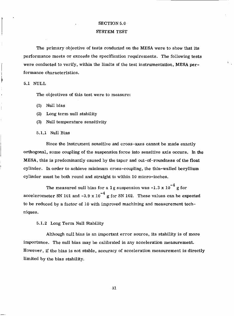
The primary objective of tests conducted on the MESA were to show that its
performance meets or exceeds the specification requirements. The following tests
were conducted to verify, within the limits of the test instrumentation, MESA per-
formance characteristics. I 1
5.1 NULL I
t The objectives of this test were to measure:
(1) Null bias
(2) Long term null stability
(3) Null temperature sensitivity
5.1.1 Null Bias
I 1
Since the instrument sensitive and cross-axes cannot be made exactly
I orthogonal, some coupling of the suspension force into sensitive axis occurs. In the
I MESA, this is predominantly caused by the taper and out-of-roundness of the float
I cylinder. In order to achieve minimum cross-coupling, the thin-walled beryllium
cylinder must be both round and straight to within 10 micro-inches.
-4 The measured null bias for a 1 g suspension was -1.3 x 10 g for -4
accelerometer SN 101 and -3.9 x 10
to be reduced by a factor of 10 with improved machining and measurement tech-
niques.
g for SN 102. These values can be expected
5.1.2 Long Term Null Stability
Although null bias is an important e r ro r source, its stability is of more
importance. The null bias may be calibrated in any acceleration measurement.
However, if the bias is not stable, accuracy of acceleration measurement is directly
limited by the bias stability.
3 1

-4 Null stability measurements were conducted with a 10 g input and the
variations automatically recorded for running periods of up to 12 hours. Figures
10, 13, and 16, show peak to peak null variations of less than 1 x 10
and SN 102.
-6 I g for SN 101
factor stability, the same order of magnitude variations occur. It may be concluded 1
I
1 5.1.3 Null Temperature Sensitivity
I The null varies with both accelerometer and electronics temperature
changes. This is due to suspension excitation amplitude change and float-electrode
carr ier gap width changes. For a 1 g suspension, values of -2 x 10 and +3.2 x 10
g/" F/g were obtained for electronics and accelerometer (SN 101) temperature
changes, respectively. A coefficient of +1.18 x 1 0 g/"F/g was obtained on accel-
erometer SN 102. These low values illustrate the high performance of the electro-
static suspension system.
I -7 -6
-6
I
5.2 SCALE FACTOR
The objectives of these tests were to adjust or measure:
(1) Channel balance
(2) Long term scale factor stability
(3) Scale factor temperature sensitivity
(4) Scale factor linearity
5.2.1 Channel Balance
The MESA system utilizes separate but identical constrainment pulse
generation channels to supply the two sets of accelerometer forcer rings. Differences
in forcer ring area and pulse transformer characteristics require compensation to
the positive and negative scale factors. This balance is achieved by adjusting the
32

pickoff bridge balance position (the electrical null) to coincide with the position of
equal pulse force (the mechanical null). Channel balance is accomplished by selection
of value and position of capacitors lASClO,-Cll, and -C12. It was set to 0.7% with
accelerometer. SN 101 and to 0.9% with SN.102.
5.2.2 Long Term Scale Factor Stability
The effect of test base on null tests mentioned in Section 5.1.2 is also a
factor in scale factor stability measurement. Scale factor stability is also dependent
on the stabilities of pulse transformer saturation current (which is determined by B+
and series resistor) and pulse transformer core temperature.
-3 Scale factor measurements were made with 10 g (full scale) inputs over
8 to 12 hour periods. Figures 11, 12, 14, 15, 1 7 , and 18 show peak to peak variations
of less than 8 x g for SN 101 and 1.5 x g for SN 102.
5.2.3 Scale Factor Temperature Sensitivity
Tests were conducted on the electronics and the accelerometer to evaluate
scale factor temperature sensitivities. The following data was obtained;
Electronics
Accelerometer
Accelerometer
+3.5 x g/"F
SN 101 5 +7.8 x g/"F
g/ I' SN i u 2 5 t6.6 10-7 - fQ I7
5.2.4 Scale Factor Linearity
Scale factor linearity e r ro r is primarily caused by variation in pulse size
with pulse rate, and is minimized by controlling the pulse core temperature. The
tests conducted on the system level a re limited by the accuracy of the resoiuiioii
and stability of the g input to the accelerometer. Since this is typically 10 g, the
linearity e r ro r coefficient would be 10 g/g at g input and 10 g/g at 10 g
input. A coefficient of less than 10
was obtained in the tests on the system.
-5
-2 -1 -4
g/g, which is within the instrumentation e r ro r , -2
In order to check pulse size variation with frequency more accurately,
the pulse generation system was tested in an analog to digital converter. The pulses
33

were compared with a precision d-c (10 ppm) voltage standard. The maximum
linearity e r ror measured was 0.05%. io
5.3 SHOCK AND VIBRATION TESTS
The system was subjected to the shock and vibration tests shown in Figure 19.
Subsequent post environment test indicated no measurable change in scale factor o r
null or failure in subsystem operation. Post environmental null and scale factor
stability test data is shown in Figures 16, 17 , and 18.
5.4 ERROR ANALYSIS
-8 An acceleration measurement accuracy of *l% or *3 x 10 g, whichever is
-4 -6 greater, is required for accelerations from 10 g to 10 g. The system er ror
sources are:
E 2 + E 2 + E 2 k n L (1) Scale factor stability Ek
n (2) Null and null stability E
L (3) Scale factor linearity E
The allowable rms e r ro r for each of the above sources is
E k = E - - EL = 0.58% n
Where E = total system e r ro r i;
5.4.1 Scale Factor Stability
As shown in Figures 11, 12, 1 4 , 1 5 , 17, and 18 and as discussed in Section -6
5.2.2, the long term scale factor stability variations were less than 1.5 x 10
peak to peak and the percent e r ror less than 0.15%, a factor of four better than the
requirement. The scale factor temperature coefficient is 1.1 x 10
O.ll%/"F. For a k5"C environment, the error contribution by the electronics is
*0.31%1; and by the accelerometer, which is temperature controlled to *2'F, is
*0.16%.
g
-6 g/"F o r
5.4.2 Null and Null Stability
-4 -7 -6 The allowable null e r ro r for a 10 g input is 5.8 x 10 g. For a 10 g
g, which is also the null e r ro r in this -8 input, the allowable system er ror is 3 x 10
3 4

-9 i case since the scale factor e r rors a re less than 5.8 x 10 g. The typical null bias
-3 The allowable linearity e r ror is 5.8 x 10 g/g. A s discussed in Section
5.2.4, the tests on a system level cannot be made to this accuracy. In the subsystem
test of the pulse generation system, the maximum er ror was 0.05% or 5 x 10 -4
g/g. i
-4 -8 is loW4 g/g, which for 10 g cross-axis suspension is 10 g. The system worst
r -6 -10 g/g/"F, the e r ror being 6 x 10 case null temperature coefficient is 3 x 10
for a 10
g/"F
g suspension and 2OF temperature control of the accelerometer. The long -4
-6 term null variation was 10 g peak to peak for a 1 g suspension, and would be in the
I -4 order of 10-l' g for a 10 g suspension.
5.4.3 Scale Factor Linearity I
35

% G b
a
0
I W k
;
W W Y
2
l i 0 r(
36

I
,
5 u 0 4
0 I
m k
x
rn c, m .-
E”
d 0 d
z m
rt m
37

._r-
I
m m k 1 $
hl
E cd rl
B a rl rl
rl 0 I-I
rn z ...
i
38

A 0 0 d u 0 I rn k
X
0 0 0 0 0 0 0 0 0 0 0 0 0 0 0 0 0 0 0 0 0
rn c, rn
E"
CJ 0 l-i
A d
39

a c9 m r(
00 Eu I c- Eu
..
a- -0 r!. 0
0 0 0 0
w -
Q .9 0-
0 0
0 0 0,
43
00
c-
a
k 0
N PI
E a l-l PI

0 0 0 0 0 0
0 0 0 rl
0, Q) 03
41

30
e-
;o
In 3 Ei - 0 0
- # I rn k
X
m
hl
E cd rl
hl rl
E a " rl
0 0 0 0 0 0 0 0 0 0 0 0 0 0 0 0 y ) d r M c * l "
42

3 G b
0
I m k
X

0 0 0 0 0 0
0 0 0 b
44
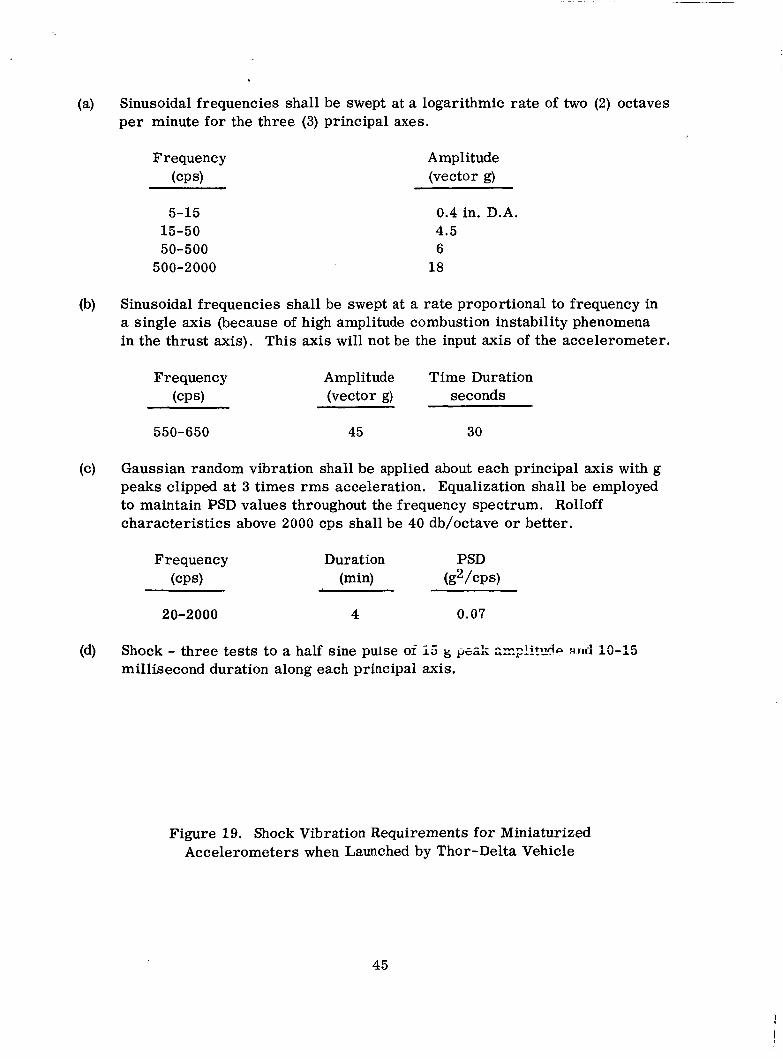
(a) Sinusoidal frequencies shall be swept at a logarithmic rate of two (2) octaves per minute for the three (3) principal axes.
Frequency (CPS)
5-15 15-50 50-500
500-2000
Amplitude (vector g)
0.4 in. D.A. 4.5 6 18
(b) Sinusoidal frequencies shall be swept at a rate proportional to frequency in a single axis (because of high amplitude combustion instability phenomena in the thrust axis). This axis will not be the input axis of the accelerometer.
Frequency Amplitude Time Duration (CPS) (vector g) seconds
550-650 45 30
(c) Gaussian random vibration shall be applied about each principal axis with g peaks clipped at 3 times rms acceleration. Equalization shall be employed to maintain PSD values throughout the frequency spectrum. Rolloff characteristics above 2000 cps shall be 40 db/octave or better.
Frequency (CPS)
Duration PSD (min) (g2/cps)
d
20-2000 4 0.07
(d) Shock - three tests to a half sine pulse oi I 5 g
millisecond duration along each principal axis. : z A ~ i i t : ~ 6 ~ nni]. 13-15
Figure 19. Shock Vibration Requirements for Miniaturized Accelerometers when Launched by Thor-Delta Vehicle
45

SECTION 6.0
CONCLUSIONS AND RECOMMENDATIONS
A concerted analytical, design, fabrication and test effort has been conducted
by the Products and Instruments Group of Bell Aerosystems Company to develop
a Miniaturized Electrostatic Accelerometer (MESA) for space applications. This
accelerometer is characterized by:
(1) Precision digital electrostatic force constrainment along the instrument sensitive axis.
(2) Variable range electrostatic suspension.
(3) The ability to withstand high launch accelerations while nonoperating.
A s discussed in the foregoing sections of this report, the instrument has
demonstrated significant performance in the critical areas of null and scale factor
variations with time and temperature. The program has also pointed out areas
where additional study and design improvement should be considered. These a re
discussed in detail below.
6.1 LOW g TESTING
The evaluation of the MESA performance is limited by current state-of-the-
zr: TF-+ insiriiiiieiit&ion. The MZSA was evaluated on a special test base which
exhibited long term stability of 10
better than 1% over a range of 10
dividing head resolution, repeatability and test base stability mclst be less than 10
to g. Bell Aerosystems has investigated several methods which appear
feasible. The practical implementation of these methods would require an additional
study and test effort.
-6 g or better. In order to achieve a test accuracy -4 -6
to 10 g, instrumentation e r rors such as -6
6.2 MECHANICAL DESIGN
A s discussed in Section 5.1.1, the nul l bias of the MESA is in the order of
g/g. The machining and measurement of the MESA proof mass tolerances of -4
10
10 micro-inches or better is required in order to achieve low null bias. The
46

I present method of measuring float roundness and straightness by mechanical gauges
is not accurate enough. The gauge causes deformation of the beryllium cylinder
and limits the measurement accuracy. A noncontact method using a capacitive pick-
off similar to that used in the MESA has been investigated. It would enable measure-
ments to be made to an accuracy of 1 micro-inch. An improvement by a factor of
10 in null bias to I g/g o r lower is possible,
6.3 ELECTRONIC DESIGN
With the availability of many circuit functions in the integrated circuit form,
a significant reduction in MESA power, volume, and weight is possible. A pre-
liminary study indicates that the electronics power could be reduced from 8 to 3
watts, volume from 105 to 50 in. , and weight from 3.8 to 2.0 pounds. The improve-
ments are particularly significant where long term operation of the MESA in a
spacecraft is required and where power consumption is important. The reliability
also would be improved since fewer components and assembly functions would be
required.
3
!
Consideration should also be given to simplified and improved system design;
in particular:
(1) Elimination of one pulse generator by using electronic switching of pulses
control and power reduction of two watts.
U s e of preregulator in power supply to achieve power conversion efficieiicy of 90% f m inpct variations of 24 to 34 vdc.
Use of duty cycle modulated temperature controllers; operating efficiency of 90% possible,
Design of automatic suspension recycling control to eliminate possibility of suspension, nonstarting , or dropout during high transient acceleration.
anu * U U l u u i i a + " . ' * - --1 '--:-e L v 6 Z V , -n.=--i+e _ _ _ _ in nmailei- oven, =ne lees C Q ~ P temperature
(2)
(3)
(4)
47

SECTION 7.0
DESIGN REVIEW
I The final design review of the MESA dealt primarily with the evaluation test
phase, the interpretation of the results a s related to the design specifications, and
the engineering analyses that established these specifications.
7.1 SYSTEM TEST DATA
The test results demonstrated were well within the specification in all areas
except:
-5 (1) Cross-Coupling - The specification (10 g/g) for cross-coupling effects
was not demonstrated primarily because of the state-of-the-art capability for measuring roundness of float. The MESA demonstrated cross-coupling effects approximately an order of magnitude larger than specified.
Power Requirements - The average operating power requirements of 15 watts (specified) is exceeded by approximately 10%.
(2)
Recommendations
(1) A s mentioned elsewhere in this report, preliminary investigation of using a capacitive pickoff device for mechanical inspection of precise parts appears to be a means of advancing the state-of-the-art and effectively reducing tns crum-c"GGlkg c r re i s .
The power consumption of the MESA can be reduced to well within re- quirements by a modification to the temperature control such that it
(2)
operates in a u i g l d ---+l.rnn A a u l Q l than _.-._ ____._ an2log mode.
7.2 FAILURES
Al l failures that occurred during tests were analyzed for cause and the
necessary action was taken to correct the problem. A total of six failures occurred,
five of which were the same part (Q2 of the suspension oscillator). Each of the Q2
(2N834) failures was caused by accidental shorting of the output to ground. To
eliminate the problem a resistor and capacitor were added to protect the transistor
from accidental shorts. The remaining failure was a power supply transistor
48

1 I
I i I I I
I I I
I
I
burned out during module testing, and was again induced by the tester and a mis-
placed test probe.
7.3 SYSTEM OPERATION
During integration and system test, interface and interaction problems re-
sulted in the following design modifications:
(1) In each CTC, a capacitor (1A3C1 and 1A3C2) was added across the bridge to minimize the effect of restoring pulses.
(2) In the suspension amplifier, potentiometer (1A4Rll) was added to balance suspension excitation voltage , and fixed capacitor (1A4C6) was added for phase adjustment.
In the output of the f trigger, resistors (1A4R14 and 15) plus diode (1A4CR12) were added to balance input impedances to multivibrators.
(4) In the two multivibrators, resistors (1A4R5, 6 , 7 , and 8) were added and the base of the flip-flops was returned to the -16 volt source instead of ground to protect against retriggering on noise pulses.
(3)
7.4 SUMMARY
In summary, the final review indicates that the test and evaluation phase
generally confirmed the results of the early engineering studies and design de-
cisions. Action taken as a result of the recommendations generated in the design
review pi-og-rzm served tn minimize the system integration and test problems. The
detailed engineering associated with the circuit and packaging review, 1.e. , paria
selection and application, thermal and mechanical analyses , in conjunction with the
tight quality control program served to respectively dirnhzte failures during the
test program.
49