Embed Size (px)
Citation preview

OWNER’S MANUAL
201 COMMERCE DRIVE • MONTGOMERYVILLE, PA 18936
215-393-4700 • 800-331-1423 • FAX 215-393-4800
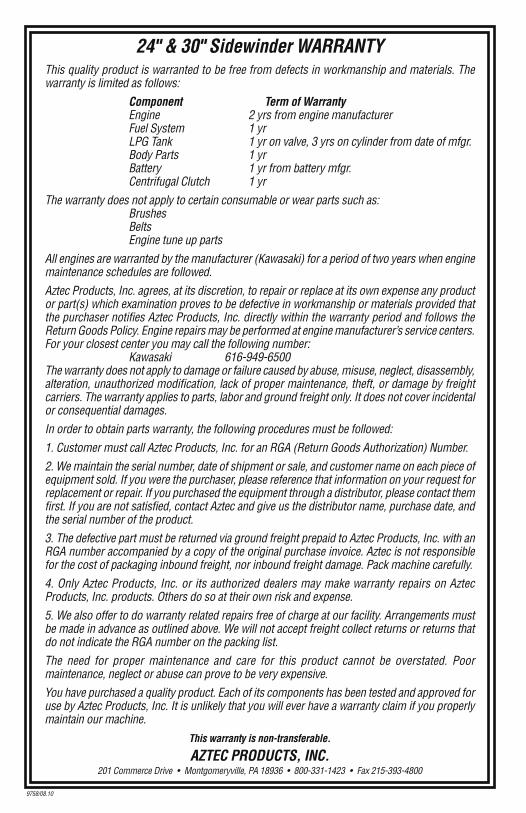
24" & 30" Sidewinder WARRANTYThis quality product is warranted to be free from defects in workmanship and materials. Thewarranty is limited as follows:
Component Term of WarrantyEngine 2 yrs from engine manufacturerFuel System 1 yrLPG Tank 1 yr on valve, 3 yrs on cylinder from date of mfgr. Body Parts 1 yrBattery 1 yr from battery mfgr.Centrifugal Clutch 1 yr
The warranty does not apply to certain consumable or wear parts such as:BrushesBeltsEngine tune up parts
All engines are warranted by the manufacturer (Kawasaki) for a period of two years when enginemaintenance schedules are followed.
Aztec Products, Inc. agrees, at its discretion, to repair or replace at its own expense any productor part(s) which examination proves to be defective in workmanship or materials provided thatthe purchaser notifies Aztec Products, Inc. directly within the warranty period and follows theReturn Goods Policy. Engine repairs may be performed at engine manufacturer’s service centers.For your closest center you may call the following number:
Kawasaki 616-949-6500The warranty does not apply to damage or failure caused by abuse, misuse, neglect, disassembly,alteration, unauthorized modification, lack of proper maintenance, theft, or damage by freightcarriers. The warranty applies to parts, labor and ground freight only. It does not cover incidentalor consequential damages.
In order to obtain parts warranty, the following procedures must be followed:
1. Customer must call Aztec Products, Inc. for an RGA (Return Goods Authorization) Number.
2. We maintain the serial number, date of shipment or sale, and customer name on each piece ofequipment sold. If you were the purchaser, please reference that information on your request forreplacement or repair. If you purchased the equipment through a distributor, please contact themfirst. If you are not satisfied, contact Aztec and give us the distributor name, purchase date, andthe serial number of the product.
3. The defective part must be returned via ground freight prepaid to Aztec Products, Inc. with anRGA number accompanied by a copy of the original purchase invoice. Aztec is not responsiblefor the cost of packaging inbound freight, nor inbound freight damage. Pack machine carefully.
4. Only Aztec Products, Inc. or its authorized dealers may make warranty repairs on AztecProducts, Inc. products. Others do so at their own risk and expense.
5. We also offer to do warranty related repairs free of charge at our facility. Arrangements mustbe made in advance as outlined above. We will not accept freight collect returns or returns thatdo not indicate the RGA number on the packing list.
The need for proper maintenance and care for this product cannot be overstated. Poormaintenance, neglect or abuse can prove to be very expensive.
You have purchased a quality product. Each of its components has been tested and approved foruse by Aztec Products, Inc. It is unlikely that you will ever have a warranty claim if you properlymaintain our machine.
This warranty is non-transferable.
AZTEC PRODUCTS, INC.201 Commerce Drive • Montgomeryville, PA 18936 • 800-331-1423 • Fax 215-393-4800
24" & 30"SIDEWINDER
(Steel Body)
9758/08.10
Powered by the EPA/Carb certified
Kawasaki 603cc Engine
SIDEWINDER PG. 11
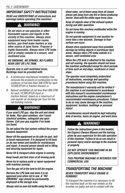
IMPORTANT SAFETY INSTRUCTIONSREAD and UNDERSTAND all instructions and warnings before operating this machine!
Operate only in well ventilated areas.Buildings must be provided with:
A. A continuous mechanical ventilation thatremoves the products of combustion to theoutdoors of not less than 300 CFM for each10,000 BTUH or fraction thereof; or
B. Natural ventilation of not less than 300 CFMfor each 10,000 BTUH input or fraction thereof, based on a maximum ofone-quarter air exchange per hour for thenet building volume.
If you smell LPG gas, stop the unit and check for leaks. Also open windows, don’t touchelectrical switches, extinguish any openflames. Call your gas supplier if no leaks are found.Do not adjust the fuel system without the properanalysis equipment.
Never tilt the equipment on its side for pad, beltor brush replacement. It is designed to tilt backon its rear wheel and handle for maintenanceand repair. A second person should aid in liftingand securing equipment for repair.Never tilt & transport while engine is running.Keep hands and feet clear of all moving parts.Never try to replace parts or repair equipmentwith machine running.Turn the gas off at the tank to kill the engine.Remove the LPG tank and store it in anapproved area when not in use. A “NOSMOKING” sign should be permanently displayed at the storage area.Always vent an over-full bottle using the tank’s
bleed valve, out of doors away from all closedplaces and away from any fire or flame producingdevice. Vent until the white vapor turns clear.Keep all objects clear of the exhaust systemduring and after operation. Do not leave this machine unattended while theengine is running.Do not operate equipment in one location formore than a few seconds. Damage to floorsurface can occur.Always store equipment away from possibledamage by falling objects in warehouse-typeareas. Always store LPG tanks outside in asecure, well-ventilated area.When the LPG tank is attached to the machineand not running, the operator should not leavethe machine unattended except for short periodsof time such as rest stops, washroom or mealstops.The operator must completely understand all instructions, warnings and operating procedures before using this machine.
The manufacturer’s warranty will be voided ifthe machine is not maintained in accordancewith this manual’s recommended maintenanceinstructions and the engine manufacturer’srecommended maintenance procedures. Failureto do so may cause damage to the machine,equipment, furniture, buildings or personalinjury!
A maintenance record should be kept indicatingdate of service, hours on engine, and work done.
TRANSPORTING THE MACHINENEVER TRANSPORT WHILE ENGINE IS RUNNING! To transport the machine it is necessary to tiltthe machine back on the rear wheels so thebrushes (or pads) are not in contact with the
PG. 2 SIDEWINDER
Do not store or use gasoline or other flammable vapors and liquids in the vicinity of this machine. Always storeequipment away from heater rooms, boilers, gas-fired water heaters or anyother source of open flame. Propane ishighly flammable. Always store LPG tanks(full or empty) outside in a secure, wellventilated area.
NO SMOKING, NO SPARKS, NO FLAMESNEAR UNIT OR LPG TANK.
WARNING!!
Follow the instructions given in this booklet,the Engine’s Owners Manual and the traininggiven by your supervisor for the safe operationof this machine. Failure to do so can result inpersonal injury and/or damage to the machineor property.
DO NOT OPERATE THIS MACHINE IN ANEXPLOSIVE ENVIRONMENT!
THIS PROPANE MACHINE IS INTENDED FORCOMMERCIAL USE.
WARNING!!
WARNING!!
KAWASAKI 603cc ENGINE
PART # DESCRIPTION PART # QTY1. Foam Hat Filter 186-271964 (1)2. Debris Screen 309-18540 (1)3. Foam Hat Seal 175-7.75*9.25*1 (1)4. Oil Pressure Switch 152-N3-0082 (1)5. Oil Filter 309-49065-7007 (1)6. Oil Drain Valve 312-504-0185 (1)7. 1 / 4 x 1 1 / 4 Key 199-NHNT-SE UND (1)8. Centrifugal Clutch 311-180007 (1)9. Exhaust Manifold Gasket 309-11060-7016 (2)10. Exhaust Manifold 152-603-MAN (1)11. Catalytic Muffler 152-603-MUF (1)12. Debris Screen Adapter 283-040-2250 (1)13. Air Filter Element 309-11013-7049 (1)14. Foam Pre Filter 309-11013-7046 (1)
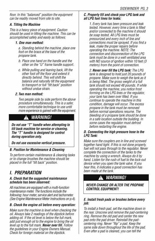
floor. In this “balanced” position the equipmentcan be readily moved from site to site.
A. Tilting the MachineThis is a heavy piece of equipment. Cautionshould be used in tilting the machine. This can beaccomplished safely and easily as follows:
1. One man method:a. Standing behind the machine, place one foot on the brace at the base of the propane tank.b. Place one hand on the handle and the other on the “U” frame handle support.
c. While pulling and leaning back, lift the other foot off the floor and extend it directly behind. This will shift the balance and naturally tilt the equipment to transport or full “tilt back” position without undue strain.
2.Two man method:Two people side by side perform the above procedure simultaneously. This is a safer, more comfortable technique to use until more experience is gained with the equipment.
B. Position for Maintenance & CleaningTo perform certain maintenance & cleaning tasksor to change brushes the machine should beplaced in the full “tilt back” position.
I. PREPARATIONA. Check that the suggested maintenanceschedule has been observed:All machines are equipped with a multi-functionmaintenance meter. The functions include the following: hour meter, service alert and tachometer.(See Engine Maintenance Meter Instructions on p.4).
B. Check the engine oil before every operation:Make sure the machine is level when checking theoil. Always take 2 readings of the dipstick beforeadding oil. If the oil level is below the full mark,add just enough oil to the engine to bring the oillevel up to the full mark. Never over fill. Followthe guidelines in your Engine Owners Manual.Check for foreign material on the dipstick.
C. Properly fill and check your LPG tank andall LPG fuel lines for leaks:
1. Every tank has been pressure and leaktested. However, every time a tank is filledand/or connected to the machine it shouldbe soap tested. All LPG lines must bepressurized and every inch of line andconnections must be sprayed. If you find aleak, make the proper repairs beforeoperating the machine. NOTE: Theconnection and disconnection of the LPGtank must be done in a well ventilated areawith NO source of ignition within 10 feet (3meters) from the point of connection.2.Never over fill the LPG tank: The LPGtank is designed to hold just 20 pounds ofpropane. Make sure to weigh the tank as itis being filled. The gross weight of a fulltank should not exceed 48 pounds. If whileoperating the machine, you notice frostforming on the LPG lines or the regulator,your tank has been over filled. If youcontinue to operate the machine in thiscondition, damage will occur. The excesspropane in the tank must be removedbefore normal operations resume. Thebleeding of a propane tank should be donein a safe location outside the building. Insome cases the regulator must defrostbefore restarting the engine.
D. Connecting the high pressure hose to theLPG Tank:Make sure the couplers are in line and screwedtogether hand tight. If this is not done properly,fuel will not pass through to the regulator. Nevercomplete the connection of the tanks to themachine by using a wrench. Always do it byhand. Listen for the rush of fuel to the lock-outdevice when you open the tank valve. If youhear this, it indicates a good connection hasbeen made at the tank.
E. Install fresh pads or brushes before everyjob:To install a fresh pad, set the machine down inthe rear. Unscrew and remove the pad-centeringring. Remove the old pad and center the newpad onto the pad driver. Reinstall the pad-centering ring. Never “flip” a pad. Keep thesame side down throughout the life of the pad.Even after a pad is cleaned, you can tell the
SIDEWINDER PG. 3PG. 10 SIDEWINDER
SIDEWINDER BRUSH OPTIONSCOLOR CHARACTERISTICS PART #
BROWN/RED Very aggressive stripping brush SW 30" 010-962STBH(4 Row) Lasts up to 1-2 million square feet SW 24" 01024-962STBH
Holds up well when doing concrete
BLUE Deep scrubbing and light stripping SW 30" 010-962SCB(5 Row) Lasts up to 1-2 million square feet SW 24" 01024-962SCB
SIDEWINDER PAD DRIVER SYSTEMDesigned for driving 10" pads. Pad grabber 111 to hold pads. Quick connect pad clips for easy padchange. Comes with Black Hi-Pro pads. Nylon bristles help prevent pads from clogging. Approximately25%-30% faster than stripping with brushes.
PAD COLOR CHARACTERISTICS PART #
BLUE Scrubbing. Use 1 per pad driver 253-08082
BLACK Stripping. Use 1 per pad driver 253-09074
Do not use “T” handle when attempting totilt back machine for service or cleaning.The “T” handle is designed for controlduring operation only.
Do not use excessive vertical pressure.
WARNING!!
NEVER CHANGE OR ALTER THE PROPANE CONTROL EQUIPMENT!
WARNING!!
FUEL SYSTEM PARTS LIST FOR 12v AND 110v MODELS
PART # DESCRIPTION PART # QTY1 QUICK COUPLER 152-700 12 LP HOSE
14" 267-P5561-14 120" 267-P5561-0410 1
3 FUEL LOK-OUT (VACUUM) 152-300 14 90 FITTING 177-116B04 15 VACUUM HOSE FITTING 166-62029 16 1 1/2" NIPPLE 177-56021 17 FUEL REGULATOR (T60) 152-50 18 FUEL HOSE FITTING 166-62039 19 FUEL LOK-OUT (12 VOLT) 152-N3-0173-1 110 FUEL REGULATOR (T-60E) 152-500 1
SIDEWINDER PG. 9PG. 4 SIDEWINDER
down side by the centering ring indentation.This practice will increase the pad life and helpmaintain a properly functioning pad driver.NEVER TILT A MACHINE ON ITS SIDE!
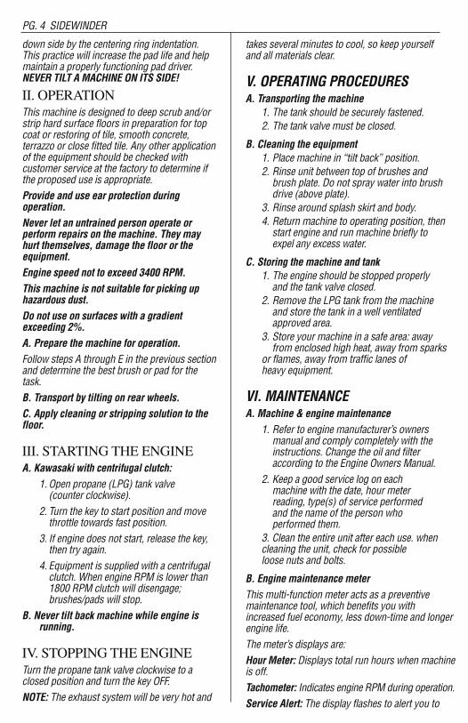
II. OPERATIONThis machine is designed to deep scrub and/orstrip hard surface floors in preparation for topcoat or restoring of tile, smooth concrete,terrazzo or close fitted tile. Any other applicationof the equipment should be checked withcustomer service at the factory to determine ifthe proposed use is appropriate.Provide and use ear protection duringoperation.Never let an untrained person operate orperform repairs on the machine. They mayhurt themselves, damage the floor or theequipment.Engine speed not to exceed 3400 RPM.This machine is not suitable for picking uphazardous dust.Do not use on surfaces with a gradientexceeding 2%.A. Prepare the machine for operation.Follow steps A through E in the previous sectionand determine the best brush or pad for thetask.B. Transport by tilting on rear wheels.C. Apply cleaning or stripping solution to thefloor.
III. STARTING THE ENGINE A. Kawasaki with centrifugal clutch:
1. Open propane (LPG) tank valve (counter clockwise).
2. Turn the key to start position and move throttle towards fast position.
3. If engine does not start, release the key, then try again.
4. Equipment is supplied with a centrifugal clutch. When engine RPM is lower than 1800 RPM clutch will disengage; brushes/pads will stop.
B. Never tilt back machine while engine isrunning.
IV. STOPPING THE ENGINETurn the propane tank valve clockwise to aclosed position and turn the key OFF.NOTE: The exhaust system will be very hot and
takes several minutes to cool, so keep yourself and all materials clear.
V. OPERATING PROCEDURESA. Transporting the machine
1. The tank should be securely fastened.2. The tank valve must be closed.
B. Cleaning the equipment1. Place machine in “tilt back” position.2. Rinse unit between top of brushes and brush plate. Do not spray water into brush drive (above plate).
3. Rinse around splash skirt and body.4. Return machine to operating position, then start engine and run machine briefly to expel any excess water.
C. Storing the machine and tank1. The engine should be stopped properly and the tank valve closed.
2. Remove the LPG tank from the machine and store the tank in a well ventilated approved area.
3. Store your machine in a safe area: away from enclosed high heat, away from sparks
or flames, away from traffic lanes of heavy equipment.
VI. MAINTENANCEA. Machine & engine maintenance
1. Refer to engine manufacturer’s owners manual and comply completely with the instructions. Change the oil and filter according to the Engine Owners Manual.
2. Keep a good service log on each machine with the date, hour meter reading, type(s) of service performed and the name of the person who performed them.
3. Clean the entire unit after each use. when cleaning the unit, check for possible loose nuts and bolts.
B. Engine maintenance meterThis multi-function meter acts as a preventivemaintenance tool, which benefits you withincreased fuel economy, less down-time and longerengine life.The meter’s displays are:Hour Meter: Displays total run hours when machineis off.Tachometer: Indicates engine RPM during operation.Service Alert: The display flashes to alert you to
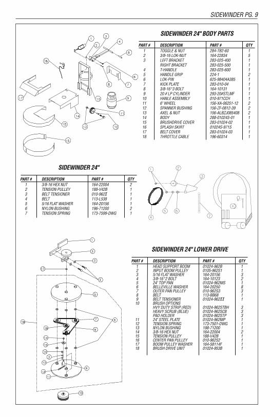
SIDEWINDER 24" BODY PARTS
PART # DESCRIPTION PART # QTY1 TOGGLE & NUT 284-TB2-60 12 3/8-16 LOK-NUT 164-22834 53 LEFT BRACKET 283-025-400 1
RIGHT BRACKET 283-025-500 14 T-HANDLE 283-025-600 15 HANDLE GRIP 224-1 26 LOK-PIN 625-98404A385 17 KICK PLATE 283-010-04 18 3/8-16*3 BOLT 164-10131 19 20 # LP CYLINDER 293-20#STLMF 110 HANLE ASSEMBLY 010-971CCH 111 6" WHEEL 156-XA-06251-12 212 SPANNER BUSHING 156-ZF-0812-39 213 AXEL & NUT 156-ALBZJ085408 214 BODY 288-01024S-01 115 BRUSHDRIVE COVER 283-01024-02 116 SPLASH SKIRT 01024S-971S 117 BELT COVER 283-01024-03 118 THROTTLE CABLE 196-60314 1
SIDEWINDER 24"
PART # DESCRIPTION PART # QTY1 3/8-16 HEX NUT 164-22004 22 TENSION PULLEY 188-V42B 13 BELT TENSIONER 010-962T 14 BELT 113-L538 15 5/16 FLAT WASHER 164-20156 16 NYLON BUSHING 196-71200 27 TENSION SPRING 173-7599-DWG 1
SIDEWINDER 24" LOWER DRIVE
PART # DESCRIPTION PART # QTY1 HEAD SUPPORT BOOM 01024-962B 12 INPUT BOOM PULLEY 0105-962S1 13 5/16 FLAT WASHER 164-20156 34 3/8-16*2 BOLT 164-10123 25 24" TOP PAN 01024-962MS 16 BELLEVILLE WASHER 164-20250 87 OUTER PAN PULLEY 010-962S3 38 BELT 113-BB68 19 BELT TENSIONER 01024-962TT 110 BRUSH OPTIONS
HVY DUTY STRIP (RED) 01024-962STBH 3HEAVY SCRUB (BLUE) 01024-962SCB 3PAD HOLDER 01024-962STP 3
11 24" STEEL PLATE 01024-962MP 112 TENSION SPRING 173-7501-DWG 113 NYLON BUSHING 198-71200 114 3/8-16 HEX NUT 164-22004 215 TENSION PULLEY 188-V42B 116 CENTER PAN PULLEY 010-962S2 117 BOOM PULLEY WASHER 164-58114F 118 BRUSH DRIVE UNIT 01024-953B 1
T
TT

SIDEWINDER PG. 5
lube and change the oil at 25 hour intervals. Theservice alert only flashes during operation and itwarns you to change the oil for only two hours.After the two hours is reached, the alert willautomatically reset to the next 25 hour interval.Therefore, it is recommended that a separatemaintenance log be kept to track oil changes.Remember that being safe is a full-time, everyday job. Follow all information posted on themachine and the LPG tank.Never allow anyone to operate this machinewho has not read or cannot understand thegiven instructions.
C. Troubleshooting the electrical system1. Check all wire connections for obviousproblems. Remove LPG tank, then removebattery box cover. Check all connectionsvisibly and physically. If any “loose”,damaged or unconnected wires arenoticed, replace or repair as needed.
2. Check the battery posts and wires. Alwayswear a face shield, safety glasses andprotective clothing when working arounda battery! The gases can be explosive andthe acid is highly corrosive to metals, clothand ALL HUMAN TISSUE (skin, eyes, etc.)If the battery post(s) are corroded, removethe wires and clean posts and wires.Applying some axle grease on the posts ofthe battery after they are cleaned will slowdown the battery corrosion process. Ifnothing obvious is noted, a more detailedinvestigation is warranted. Before anysuch troubleshooting begins, the followingthings should be done:
3. Replace propane LPG tank with one froma machine that runs.
4. Charge the battery or provide an absolutesource of 12 volt DC power capable of 50amperes total output. (A pair of good jumper cables from your car or truckbattery will suffice.) Equip yourself with aninexpensive 12 volt test light.
5. If the trouble seems to be in the electricalcontrol equipment, you may wish todisconnect the starter from the system soas to check the system without spinningthe engine.
6. Battery rundown. A common problem isletting the battery run down. What usuallyhappens is that it takes the crew a few jobs toget used to the whole system, so the machineis stopped and started quite often. Key left inon position, when engine is turned off, willresult in battery running down—dying.
D. Troubleshooting Main Drive BeltsIf the engine runs, but the drive unit will not engage,this is usually related to the main drive brush belt orbelt tension spring. Without removing the drive unityou can check and fix the following:
1. Remove the four 3/8" bolts holding the beltcover to the body. Remove the (1) 3/8" boltholding the muffler bracket to the belt cover.Check if belt tension spring is attached to theidler spring mount bolt on the body.
2. Check to see if belts have come off of inputpulley or centrifugal clutch. If so, install beltsback on the pulley. Note: If belts come offagain they are probably worn or stretchedand need replacement.
3. To replace engine drive belts:Loosen the (3) bolts on the right hand sideof the upper deck approximately 4 to 5 turns.Be sure at least half of the bolt threadsremain engaged. Place machine in the tilt-back position. Remove old or worn belts andreplace them with the new ones. Removeone end of the tension spring to aid ininstallation of new belts. Check for wear onthe springs and their catches.
4. Re-attach tension spring to mount bolt andtighten (3) 1/2" bolts. Slide the belt cover intoplace and start (4) 3/8" bolts into belt cover(hand tighten only). Start (1) 3/8" bolt intomuffler bracket and belt cover, then tightenall (5) 3/8" bolts.
5. To change the brush drive belt:Removethree (3) bolts on the right hand side ofupper deck (use a 3/4" wrench). Slowly raisefront of machine off the floor. Remove InputBoom Pulley and Boom Arm from BrushDrive by using the two 3/4" wrenches—sliding them into the slots in the boom pulleyshaft to unscrew the pulley from the shaft.Remove six (6) bolts from bottom side ofBrush Drive and split Brush Drive Top Panand Brush Drive Plate. Remove worn beltand replace. It is a good idea at this time tocheck the Tension Spring, bearings and idlerfor damage and replace them if necessary.
Engine OilCheck the engine oil daily before starting theengine otherwise shortage of the engine oil maycause serious damage to the engine such asseizure.• Place the engine on a level surface. Clean thearea around the oil gauge before removing it.
• Remove the oil gauge and wipe it with a cleancloth.
• Pour the oil slowly to “FULL” mark on the oil
PG. 8 SIDEWINDER
SIDEWINDER 30" BODY PARTS
PART # DESCRIPTION PART # QTY1 TOGGLE & NUT 284-TB2-60 12 3/8-16 LOK-NUT 164-22834 53 LEFT BRACKET 283-025-400 1
RIGHT BRACKET 283-025-500 14 T-HANDLE 283-025-600 15 HANDLE GRIP 224-1 26 LOK-PIN 625-98404A385 17 KICK PLATE 283-010-04 18 3/8-16*3 BOLT 164-10131 19 20 # LP CYLINDER 293-20#STLMF 110 HANLE ASSEMBLY 010-971CCH 111 6" WHEEL 156-XA-06251-12 212 SPANNER BUSHING 156-ZF-0812-39 213 AXEL & NUT 156-ALBZJ085408 214 BODY 288-010S-01 115 BRUSHDRIVE COVER 283-010-5-02 116 SPLASH SKIRT 010-50971S 117 BELT COVER 283-01024-03 118 THROTTLE CABLE 196-60314 1
SIDEWINDER 30"
PART # DESCRIPTION PART # QTY1 3/8-16 HEX NUT 164-22004 22 TENSION PULLEY 188-V42B 13 BELT TENSIONER 010-962T 14 BELT 113-L537 15 5/16 FLAT WASHER 164-20156 16 NYLON BUSHING 196-71200 27 TENSION SPRING 173-7599-DWG 1
SIDEWINDER 30" LOWER DRIVE
PART # DESCRIPTION PART # QTY1 HEAD SUPPORT BOOM 010-962B 12 INPUT BOOM PULLEY 010-962S1 13 5/16 FLAT WASHER 164-20156 34 3/8-16*2 BOLT 164-10123 25 24" TOP PAN 010-962MS 16 BELLEVILLE WASHER 164-20250 87 OUTER PAN PULLEY 010-962S3 38 BELT 113-BB81 19 BELT TENSIONER 010-962TT 110 BRUSH OPTIONS
HVY DUTY STRIP (RED) 010-962STBH 3HEAVY SCRUB (BLUE) 010-962SCB 3PAD HOLDER 010-962STP 3
11 30" STEEL PLATE 010-962MP 112 TENSION SPRING 173-7599-DWG 113 NYLON BUSHING 198-71200 114 3/8-16 HEX NUT 164-22004 215 TENSION PULLEY 188-V42B 116 CENTER PAN PULLEY 010-962S2 117 BOOM PULLEY WASHER 164-58114F 118 BRUSH DRIVE UNIT 010-953B 1
T
TT
!
!
SIDEWINDER PG. 7PG. 6 SIDEWINDER
gauge.• Insert the oil gauge into the tube WITHOUTSCREWING IT IN.
• Remove the oil gauge to check the oil level.The oil level should be between “ADD” and“FULL” marks. Do not overfill.
• Install and tighten the oil gauge.
KAWASAKI ENGINESTune-up SpecificationsITEM SPECIFICATIONSIgnition Timing Unadjustable
Spark Plugs: Champion – RCJ8YGap 0.75 mm (0.30 in)
Low Idle Speed 1500 RPM
High Idle Speed 3400 RPM
Valve Clearance IN: 0.10-0.15 mm(0.004-0.006 in)EX: 0.10-0.15 mm(0.004-0.006 in)
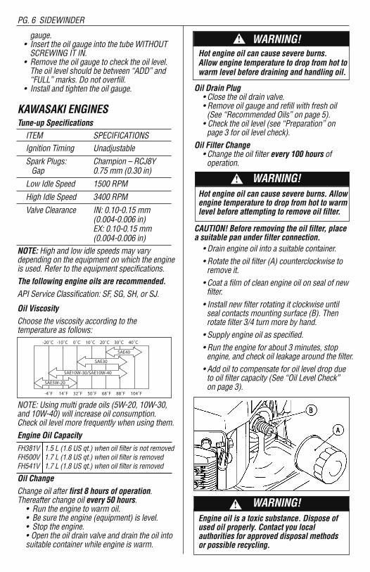
NOTE: High and low idle speeds may varydepending on the equipment on which the engineis used. Refer to the equipment specifications.The following engine oils are recommended.API Service Classification: SF, SG, SH, or SJ.
Oil ViscosityChoose the viscosity according to thetemperature as follows:
NOTE: Using multi grade oils (5W-20, 10W-30,and 10W-40) will increase oil consumption.Check oil level more frequently when using them.Engine Oil CapacityFH381V 1.5 L (1.6 US qt.) when oil filter is not removedFH500V 1.7 L (1.8 US qt.) when oil filter is removedFH541V 1.7 L (1.8 US qt.) when oil filter is removed
Oil ChangeChange oil after first 8 hours of operation.Thereafter change oil every 50 hours.• Run the engine to warm oil.• Be sure the engine (equipment) is level.• Stop the engine.• Open the oil drain valve and drain the oil intosuitable container while engine is warm.
WARNING!Hot engine oil can cause severe burns. Allow engine temperature to drop from hot towarm level before draining and handling oil.
Oil Drain Plug• Close the oil drain valve.• Remove oil gauge and refill with fresh oil (See “Recommended Oils” on page 5).• Check the oil level (see “Preparation” on page 3 for oil level check).
Oil Filter Change• Change the oil filter every 100 hours of operation.
WARNING!Hot engine oil can cause severe burns. Allowengine temperature to drop from hot to warmlevel before attempting to remove oil filter.
CAUTION! Before removing the oil filter, placea suitable pan under filter connection.• Drain engine oil into a suitable container.• Rotate the oil filter (A) counterclockwise to remove it.• Coat a film of clean engine oil on seal of new filter.• Install new filter rotating it clockwise until seal contacts mounting surface (B). Then rotate filter 3/4 turn more by hand.• Supply engine oil as specified.• Run the engine for about 3 minutes, stop engine, and check oil leakage around the filter.• Add oil to compensate for oil level drop due to oil filter capacity (See “Oil Level Check” on page 3).
WARNING!Engine oil is a toxic substance. Dispose ofused oil properly. Contact you local authorities for approved disposal methods or possible recycling.
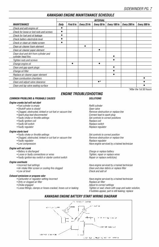
KAWASAKI ENGINE MAINTENANCE SCHEDULEINTERVAL
MAINTENANCE Daily First 8 hr. Every 25 Hr. Every 50 hr. Every 100 hr. Every 200 hr. Every 300 hr.Check and add engine oil •Check for loose or lost nuts and screws •Check for fuel and oil leakage •Check battery electrolyte level •Check or clean air intake screen •Clean air cleaner foam element •Clean air cleaner paper element •Clean dust and dirt from cylinder and cylinder head fins •Tighten nuts and screws •Change engine oil • •Clean and gap spark plugs •Change oil filter •Replace air cleaner paper element •Clean combustion chambers •Clean and adjust valve clearance •* •Clean and lap valve seating surface •
*After the 1st 50 hours
ENGINE TROUBLESHOOTINGCOMMON PROBLEMS & PROBABLE CAUSES SOLUTIONS
Engine cranks but will not start• Fuel cylinder is empty Refill cylinder• Shutoff valve is closed Open valve• Clogged, obstructed, kinked or cut fuel or vacuum line Remove obstruction or replace line• Spark plug lead disconnected Connect lead to spark plug• Faulty choke or throttle settings Set controls to correct positions• Faulty ignition coil Replace coil• Faulty kill switch Replace switch• Faulty regulator Replace regulator
Engine starts hard• Faulty choke or throttle settings Set controls to correct position• Clogged, obstructed, kinked or cut fuel or vacuum line Remove obstruction or replace line• Faulty regulator Replace regulator• Low compression Have engine serviced by a trained technician
Engine will not crank• Battery is discharged Charge or replace battery• Loose or faulty connections or wires Tighten, repair or replace wires• Faulty ignition key switch or starter control switch Repair or replace switch(es)
Engine overheats• Incorrect fuel settings Have engine serviced by a trained technician• Air intake filter screen or cooling fins clogged Clean and clear debris or replace filter • Low oil level Check and add oil
Exhaust emissions or propane odor• Carburetor or regulator setting incorrect Have engine serviced by a trained technician• Dirty or clogged air filter Replace air filter• Choke engaged Adjust to correct settings• Loose fittings, clamps or hoses cracked, hoses cut or leaking Tighten or seal; check with soap and water solution,
if bubbles appear, part is still leaking; replace
KAWASAKI ENGINE BATTERY START WIRING DIAGRAM
-20˚C -10˚C 0˚C 10˚C 20˚C 30˚C 40˚C
-4˚F 14˚F 32˚F 50˚F 68˚F 88˚F 104˚F
SAE5W-20
SAE30
SAE40
SAE10W-30/SAE10W-40
!
!
!
SIDEWINDER PG. 7PG. 6 SIDEWINDER
gauge.• Insert the oil gauge into the tube WITHOUTSCREWING IT IN.
• Remove the oil gauge to check the oil level.The oil level should be between “ADD” and“FULL” marks. Do not overfill.
• Install and tighten the oil gauge.
KAWASAKI ENGINESTune-up SpecificationsITEM SPECIFICATIONSIgnition Timing Unadjustable
Spark Plugs: Champion – RCJ8YGap 0.75 mm (0.30 in)
Low Idle Speed 1500 RPM
High Idle Speed 3400 RPM
Valve Clearance IN: 0.10-0.15 mm(0.004-0.006 in)EX: 0.10-0.15 mm(0.004-0.006 in)
NOTE: High and low idle speeds may varydepending on the equipment on which the engineis used. Refer to the equipment specifications.The following engine oils are recommended.API Service Classification: SF, SG, SH, or SJ.
Oil ViscosityChoose the viscosity according to thetemperature as follows:
NOTE: Using multi grade oils (5W-20, 10W-30,and 10W-40) will increase oil consumption.Check oil level more frequently when using them.Engine Oil CapacityFH381V 1.5 L (1.6 US qt.) when oil filter is not removedFH500V 1.7 L (1.8 US qt.) when oil filter is removedFH541V 1.7 L (1.8 US qt.) when oil filter is removed
Oil ChangeChange oil after first 8 hours of operation.Thereafter change oil every 50 hours.• Run the engine to warm oil.• Be sure the engine (equipment) is level.• Stop the engine.• Open the oil drain valve and drain the oil intosuitable container while engine is warm.
WARNING!Hot engine oil can cause severe burns. Allow engine temperature to drop from hot towarm level before draining and handling oil.
Oil Drain Plug• Close the oil drain valve.• Remove oil gauge and refill with fresh oil (See “Recommended Oils” on page 5).• Check the oil level (see “Preparation” on page 3 for oil level check).
Oil Filter Change• Change the oil filter every 100 hours of operation.
WARNING!Hot engine oil can cause severe burns. Allowengine temperature to drop from hot to warmlevel before attempting to remove oil filter.
CAUTION! Before removing the oil filter, placea suitable pan under filter connection.• Drain engine oil into a suitable container.• Rotate the oil filter (A) counterclockwise to remove it.• Coat a film of clean engine oil on seal of new filter.• Install new filter rotating it clockwise until seal contacts mounting surface (B). Then rotate filter 3/4 turn more by hand.• Supply engine oil as specified.• Run the engine for about 3 minutes, stop engine, and check oil leakage around the filter.• Add oil to compensate for oil level drop due to oil filter capacity (See “Oil Level Check” on page 3).
WARNING!Engine oil is a toxic substance. Dispose ofused oil properly. Contact you local authorities for approved disposal methods or possible recycling.
KAWASAKI ENGINE MAINTENANCE SCHEDULEINTERVAL
MAINTENANCE Daily First 8 hr. Every 25 Hr. Every 50 hr. Every 100 hr. Every 200 hr. Every 300 hr.Check and add engine oil •Check for loose or lost nuts and screws •Check for fuel and oil leakage •Check battery electrolyte level •Check or clean air intake screen •Clean air cleaner foam element •Clean air cleaner paper element •Clean dust and dirt from cylinder and cylinder head fins •Tighten nuts and screws •Change engine oil • •Clean and gap spark plugs •Change oil filter •Replace air cleaner paper element •Clean combustion chambers •Clean and adjust valve clearance •* •Clean and lap valve seating surface •
*After the 1st 50 hours
ENGINE TROUBLESHOOTINGCOMMON PROBLEMS & PROBABLE CAUSES SOLUTIONS
Engine cranks but will not start• Fuel cylinder is empty Refill cylinder• Shutoff valve is closed Open valve• Clogged, obstructed, kinked or cut fuel or vacuum line Remove obstruction or replace line• Spark plug lead disconnected Connect lead to spark plug• Faulty choke or throttle settings Set controls to correct positions• Faulty ignition coil Replace coil• Faulty kill switch Replace switch• Faulty regulator Replace regulator
Engine starts hard• Faulty choke or throttle settings Set controls to correct position• Clogged, obstructed, kinked or cut fuel or vacuum line Remove obstruction or replace line• Faulty regulator Replace regulator• Low compression Have engine serviced by a trained technician
Engine will not crank• Battery is discharged Charge or replace battery• Loose or faulty connections or wires Tighten, repair or replace wires• Faulty ignition key switch or starter control switch Repair or replace switch(es)
Engine overheats• Incorrect fuel settings Have engine serviced by a trained technician• Air intake filter screen or cooling fins clogged Clean and clear debris or replace filter • Low oil level Check and add oil
Exhaust emissions or propane odor• Carburetor or regulator setting incorrect Have engine serviced by a trained technician• Dirty or clogged air filter Replace air filter• Choke engaged Adjust to correct settings• Loose fittings, clamps or hoses cracked, hoses cut or leaking Tighten or seal; check with soap and water solution,
if bubbles appear, part is still leaking; replace
KAWASAKI ENGINE BATTERY START WIRING DIAGRAM
-20˚C -10˚C 0˚C 10˚C 20˚C 30˚C 40˚C
-4˚F 14˚F 32˚F 50˚F 68˚F 88˚F 104˚F
SAE5W-20
SAE30
SAE40
SAE10W-30/SAE10W-40
!

SIDEWINDER PG. 5
lube and change the oil at 25 hour intervals. Theservice alert only flashes during operation and itwarns you to change the oil for only two hours.After the two hours is reached, the alert willautomatically reset to the next 25 hour interval.Therefore, it is recommended that a separatemaintenance log be kept to track oil changes.Remember that being safe is a full-time, everyday job. Follow all information posted on themachine and the LPG tank.Never allow anyone to operate this machinewho has not read or cannot understand thegiven instructions.
C. Troubleshooting the electrical system1. Check all wire connections for obviousproblems. Remove LPG tank, then removebattery box cover. Check all connectionsvisibly and physically. If any “loose”,damaged or unconnected wires arenoticed, replace or repair as needed.
2. Check the battery posts and wires. Alwayswear a face shield, safety glasses andprotective clothing when working arounda battery! The gases can be explosive andthe acid is highly corrosive to metals, clothand ALL HUMAN TISSUE (skin, eyes, etc.)If the battery post(s) are corroded, removethe wires and clean posts and wires.Applying some axle grease on the posts ofthe battery after they are cleaned will slowdown the battery corrosion process. Ifnothing obvious is noted, a more detailedinvestigation is warranted. Before anysuch troubleshooting begins, the followingthings should be done:
3. Replace propane LPG tank with one froma machine that runs.
4. Charge the battery or provide an absolutesource of 12 volt DC power capable of 50amperes total output. (A pair of good jumper cables from your car or truckbattery will suffice.) Equip yourself with aninexpensive 12 volt test light.
5. If the trouble seems to be in the electricalcontrol equipment, you may wish todisconnect the starter from the system soas to check the system without spinningthe engine.
6. Battery rundown. A common problem isletting the battery run down. What usuallyhappens is that it takes the crew a few jobs toget used to the whole system, so the machineis stopped and started quite often. Key left inon position, when engine is turned off, willresult in battery running down—dying.
D. Troubleshooting Main Drive BeltsIf the engine runs, but the drive unit will not engage,this is usually related to the main drive brush belt orbelt tension spring. Without removing the drive unityou can check and fix the following:
1. Remove the four 3/8" bolts holding the beltcover to the body. Remove the (1) 3/8" boltholding the muffler bracket to the belt cover.Check if belt tension spring is attached to theidler spring mount bolt on the body.
2. Check to see if belts have come off of inputpulley or centrifugal clutch. If so, install beltsback on the pulley. Note: If belts come offagain they are probably worn or stretchedand need replacement.
3. To replace engine drive belts:Loosen the (3) bolts on the right hand sideof the upper deck approximately 4 to 5 turns.Be sure at least half of the bolt threadsremain engaged. Place machine in the tilt-back position. Remove old or worn belts andreplace them with the new ones. Removeone end of the tension spring to aid ininstallation of new belts. Check for wear onthe springs and their catches.
4. Re-attach tension spring to mount bolt andtighten (3) 1/2" bolts. Slide the belt cover intoplace and start (4) 3/8" bolts into belt cover(hand tighten only). Start (1) 3/8" bolt intomuffler bracket and belt cover, then tightenall (5) 3/8" bolts.
5. To change the brush drive belt:Removethree (3) bolts on the right hand side ofupper deck (use a 3/4" wrench). Slowly raisefront of machine off the floor. Remove InputBoom Pulley and Boom Arm from BrushDrive by using the two 3/4" wrenches—sliding them into the slots in the boom pulleyshaft to unscrew the pulley from the shaft.Remove six (6) bolts from bottom side ofBrush Drive and split Brush Drive Top Panand Brush Drive Plate. Remove worn beltand replace. It is a good idea at this time tocheck the Tension Spring, bearings and idlerfor damage and replace them if necessary.
Engine OilCheck the engine oil daily before starting theengine otherwise shortage of the engine oil maycause serious damage to the engine such asseizure.• Place the engine on a level surface. Clean thearea around the oil gauge before removing it.
• Remove the oil gauge and wipe it with a cleancloth.
• Pour the oil slowly to “FULL” mark on the oil
PG. 8 SIDEWINDER
SIDEWINDER 30" BODY PARTS
PART # DESCRIPTION PART # QTY1 TOGGLE & NUT 284-TB2-60 12 3/8-16 LOK-NUT 164-22834 53 LEFT BRACKET 283-025-400 1
RIGHT BRACKET 283-025-500 14 T-HANDLE 283-025-600 15 HANDLE GRIP 224-1 26 LOK-PIN 625-98404A385 17 KICK PLATE 283-010-04 18 3/8-16*3 BOLT 164-10131 19 20 # LP CYLINDER 293-20#STLMF 110 HANLE ASSEMBLY 010-971CCH 111 6" WHEEL 156-XA-06251-12 212 SPANNER BUSHING 156-ZF-0812-39 213 AXEL & NUT 156-ALBZJ085408 214 BODY 288-010S-01 115 BRUSHDRIVE COVER 283-010-5-02 116 SPLASH SKIRT 010-50971S 117 BELT COVER 283-01024-03 118 THROTTLE CABLE 196-60314 1
SIDEWINDER 30"
PART # DESCRIPTION PART # QTY1 3/8-16 HEX NUT 164-22004 22 TENSION PULLEY 188-V42B 13 BELT TENSIONER 010-962T 14 BELT 113-L537 15 5/16 FLAT WASHER 164-20156 16 NYLON BUSHING 196-71200 27 TENSION SPRING 173-7599-DWG 1
SIDEWINDER 30" LOWER DRIVE
PART # DESCRIPTION PART # QTY1 HEAD SUPPORT BOOM 010-962B 12 INPUT BOOM PULLEY 010-962S1 13 5/16 FLAT WASHER 164-20156 34 3/8-16*2 BOLT 164-10123 25 24" TOP PAN 010-962MS 16 BELLEVILLE WASHER 164-20250 87 OUTER PAN PULLEY 010-962S3 38 BELT 113-BB81 19 BELT TENSIONER 010-962TT 110 BRUSH OPTIONS
HVY DUTY STRIP (RED) 010-962STBH 3HEAVY SCRUB (BLUE) 010-962SCB 3PAD HOLDER 010-962STP 3
11 30" STEEL PLATE 010-962MP 112 TENSION SPRING 173-7599-DWG 113 NYLON BUSHING 198-71200 114 3/8-16 HEX NUT 164-22004 215 TENSION PULLEY 188-V42B 116 CENTER PAN PULLEY 010-962S2 117 BOOM PULLEY WASHER 164-58114F 118 BRUSH DRIVE UNIT 010-953B 1
T
TT
SIDEWINDER PG. 9PG. 4 SIDEWINDER
down side by the centering ring indentation.This practice will increase the pad life and helpmaintain a properly functioning pad driver.NEVER TILT A MACHINE ON ITS SIDE!
II. OPERATIONThis machine is designed to deep scrub and/orstrip hard surface floors in preparation for topcoat or restoring of tile, smooth concrete,terrazzo or close fitted tile. Any other applicationof the equipment should be checked withcustomer service at the factory to determine ifthe proposed use is appropriate.Provide and use ear protection duringoperation.Never let an untrained person operate orperform repairs on the machine. They mayhurt themselves, damage the floor or theequipment.Engine speed not to exceed 3400 RPM.This machine is not suitable for picking uphazardous dust.Do not use on surfaces with a gradientexceeding 2%.A. Prepare the machine for operation.Follow steps A through E in the previous sectionand determine the best brush or pad for thetask.B. Transport by tilting on rear wheels.C. Apply cleaning or stripping solution to thefloor.
III. STARTING THE ENGINE A. Kawasaki with centrifugal clutch:
1. Open propane (LPG) tank valve (counter clockwise).
2. Turn the key to start position and move throttle towards fast position.
3. If engine does not start, release the key, then try again.
4. Equipment is supplied with a centrifugal clutch. When engine RPM is lower than 1800 RPM clutch will disengage; brushes/pads will stop.
B. Never tilt back machine while engine isrunning.
IV. STOPPING THE ENGINETurn the propane tank valve clockwise to aclosed position and turn the key OFF.NOTE: The exhaust system will be very hot and
takes several minutes to cool, so keep yourself and all materials clear.
V. OPERATING PROCEDURESA. Transporting the machine
1. The tank should be securely fastened.2. The tank valve must be closed.
B. Cleaning the equipment1. Place machine in “tilt back” position.2. Rinse unit between top of brushes and brush plate. Do not spray water into brush drive (above plate).
3. Rinse around splash skirt and body.4. Return machine to operating position, then start engine and run machine briefly to expel any excess water.
C. Storing the machine and tank1. The engine should be stopped properly and the tank valve closed.
2. Remove the LPG tank from the machine and store the tank in a well ventilated approved area.
3. Store your machine in a safe area: away from enclosed high heat, away from sparks
or flames, away from traffic lanes of heavy equipment.
VI. MAINTENANCEA. Machine & engine maintenance
1. Refer to engine manufacturer’s owners manual and comply completely with the instructions. Change the oil and filter according to the Engine Owners Manual.
2. Keep a good service log on each machine with the date, hour meter reading, type(s) of service performed and the name of the person who performed them.
3. Clean the entire unit after each use. when cleaning the unit, check for possible loose nuts and bolts.
B. Engine maintenance meterThis multi-function meter acts as a preventivemaintenance tool, which benefits you withincreased fuel economy, less down-time and longerengine life.The meter’s displays are:Hour Meter: Displays total run hours when machineis off.Tachometer: Indicates engine RPM during operation.Service Alert: The display flashes to alert you to
SIDEWINDER 24" BODY PARTS
PART # DESCRIPTION PART # QTY1 TOGGLE & NUT 284-TB2-60 12 3/8-16 LOK-NUT 164-22834 53 LEFT BRACKET 283-025-400 1
RIGHT BRACKET 283-025-500 14 T-HANDLE 283-025-600 15 HANDLE GRIP 224-1 26 LOK-PIN 625-98404A385 17 KICK PLATE 283-010-04 18 3/8-16*3 BOLT 164-10131 19 20 # LP CYLINDER 293-20#STLMF 110 HANLE ASSEMBLY 010-971CCH 111 6" WHEEL 156-XA-06251-12 212 SPANNER BUSHING 156-ZF-0812-39 213 AXEL & NUT 156-ALBZJ085408 214 BODY 288-01024S-01 115 BRUSHDRIVE COVER 283-01024-02 116 SPLASH SKIRT 01024S-971S 117 BELT COVER 283-01024-03 118 THROTTLE CABLE 196-60314 1
SIDEWINDER 24"
PART # DESCRIPTION PART # QTY1 3/8-16 HEX NUT 164-22004 22 TENSION PULLEY 188-V42B 13 BELT TENSIONER 010-962T 14 BELT 113-L538 15 5/16 FLAT WASHER 164-20156 16 NYLON BUSHING 196-71200 27 TENSION SPRING 173-7599-DWG 1
SIDEWINDER 24" LOWER DRIVE
PART # DESCRIPTION PART # QTY1 HEAD SUPPORT BOOM 01024-962B 12 INPUT BOOM PULLEY 0105-962S1 13 5/16 FLAT WASHER 164-20156 34 3/8-16*2 BOLT 164-10123 25 24" TOP PAN 01024-962MS 16 BELLEVILLE WASHER 164-20250 87 OUTER PAN PULLEY 010-962S3 38 BELT 113-BB68 19 BELT TENSIONER 01024-962TT 110 BRUSH OPTIONS
HVY DUTY STRIP (RED) 01024-962STBH 3HEAVY SCRUB (BLUE) 01024-962SCB 3PAD HOLDER 01024-962STP 3
11 24" STEEL PLATE 01024-962MP 112 TENSION SPRING 173-7501-DWG 113 NYLON BUSHING 198-71200 114 3/8-16 HEX NUT 164-22004 215 TENSION PULLEY 188-V42B 116 CENTER PAN PULLEY 010-962S2 117 BOOM PULLEY WASHER 164-58114F 118 BRUSH DRIVE UNIT 01024-953B 1
T
TT

floor. In this “balanced” position the equipmentcan be readily moved from site to site.
A. Tilting the MachineThis is a heavy piece of equipment. Cautionshould be used in tilting the machine. This can beaccomplished safely and easily as follows:
1. One man method:a. Standing behind the machine, place one foot on the brace at the base of the propane tank.b. Place one hand on the handle and the other on the “U” frame handle support.
c. While pulling and leaning back, lift the other foot off the floor and extend it directly behind. This will shift the balance and naturally tilt the equipment to transport or full “tilt back” position without undue strain.
2.Two man method:Two people side by side perform the above procedure simultaneously. This is a safer, more comfortable technique to use until more experience is gained with the equipment.
B. Position for Maintenance & CleaningTo perform certain maintenance & cleaning tasksor to change brushes the machine should beplaced in the full “tilt back” position.
I. PREPARATIONA. Check that the suggested maintenanceschedule has been observed:All machines are equipped with a multi-functionmaintenance meter. The functions include the following: hour meter, service alert and tachometer.(See Engine Maintenance Meter Instructions on p.4).
B. Check the engine oil before every operation:Make sure the machine is level when checking theoil. Always take 2 readings of the dipstick beforeadding oil. If the oil level is below the full mark,add just enough oil to the engine to bring the oillevel up to the full mark. Never over fill. Followthe guidelines in your Engine Owners Manual.Check for foreign material on the dipstick.
C. Properly fill and check your LPG tank andall LPG fuel lines for leaks:
1. Every tank has been pressure and leaktested. However, every time a tank is filledand/or connected to the machine it shouldbe soap tested. All LPG lines must bepressurized and every inch of line andconnections must be sprayed. If you find aleak, make the proper repairs beforeoperating the machine. NOTE: Theconnection and disconnection of the LPGtank must be done in a well ventilated areawith NO source of ignition within 10 feet (3meters) from the point of connection.2.Never over fill the LPG tank: The LPGtank is designed to hold just 20 pounds ofpropane. Make sure to weigh the tank as itis being filled. The gross weight of a fulltank should not exceed 48 pounds. If whileoperating the machine, you notice frostforming on the LPG lines or the regulator,your tank has been over filled. If youcontinue to operate the machine in thiscondition, damage will occur. The excesspropane in the tank must be removedbefore normal operations resume. Thebleeding of a propane tank should be donein a safe location outside the building. Insome cases the regulator must defrostbefore restarting the engine.
D. Connecting the high pressure hose to theLPG Tank:Make sure the couplers are in line and screwedtogether hand tight. If this is not done properly,fuel will not pass through to the regulator. Nevercomplete the connection of the tanks to themachine by using a wrench. Always do it byhand. Listen for the rush of fuel to the lock-outdevice when you open the tank valve. If youhear this, it indicates a good connection hasbeen made at the tank.
E. Install fresh pads or brushes before everyjob:To install a fresh pad, set the machine down inthe rear. Unscrew and remove the pad-centeringring. Remove the old pad and center the newpad onto the pad driver. Reinstall the pad-centering ring. Never “flip” a pad. Keep thesame side down throughout the life of the pad.Even after a pad is cleaned, you can tell the
SIDEWINDER PG. 3PG. 10 SIDEWINDER
SIDEWINDER BRUSH OPTIONSCOLOR CHARACTERISTICS PART #
BROWN/RED Very aggressive stripping brush SW 30" 010-962STBH(4 Row) Lasts up to 1-2 million square feet SW 24" 01024-962STBH
Holds up well when doing concrete
BLUE Deep scrubbing and light stripping SW 30" 010-962SCB(5 Row) Lasts up to 1-2 million square feet SW 24" 01024-962SCB
SIDEWINDER PAD DRIVER SYSTEMDesigned for driving 10" pads. Pad grabber 111 to hold pads. Quick connect pad clips for easy padchange. Comes with Black Hi-Pro pads. Nylon bristles help prevent pads from clogging. Approximately25%-30% faster than stripping with brushes.
PAD COLOR CHARACTERISTICS PART #
BLUE Scrubbing. Use 1 per pad driver 253-08082
BLACK Stripping. Use 1 per pad driver 253-09074
Do not use “T” handle when attempting totilt back machine for service or cleaning.The “T” handle is designed for controlduring operation only.
Do not use excessive vertical pressure.
WARNING!!
NEVER CHANGE OR ALTER THE PROPANE CONTROL EQUIPMENT!
WARNING!!
FUEL SYSTEM PARTS LIST FOR 12v AND 110v MODELS
PART # DESCRIPTION PART # QTY1 QUICK COUPLER 152-700 12 LP HOSE
14" 267-P5561-14 120" 267-P5561-0410 1
3 FUEL LOK-OUT (VACUUM) 152-300 14 90 FITTING 177-116B04 15 VACUUM HOSE FITTING 166-62029 16 1 1/2" NIPPLE 177-56021 17 FUEL REGULATOR (T60) 152-50 18 FUEL HOSE FITTING 166-62039 19 FUEL LOK-OUT (12 VOLT) 152-N3-0173-1 110 FUEL REGULATOR (T-60E) 152-500 1

SIDEWINDER PG. 11
IMPORTANT SAFETY INSTRUCTIONSREAD and UNDERSTAND all instructions and warnings before operating this machine!
Operate only in well ventilated areas.Buildings must be provided with:
A. A continuous mechanical ventilation thatremoves the products of combustion to theoutdoors of not less than 300 CFM for each10,000 BTUH or fraction thereof; or
B. Natural ventilation of not less than 300 CFMfor each 10,000 BTUH input or fraction thereof, based on a maximum ofone-quarter air exchange per hour for thenet building volume.
If you smell LPG gas, stop the unit and check for leaks. Also open windows, don’t touchelectrical switches, extinguish any openflames. Call your gas supplier if no leaks are found.Do not adjust the fuel system without the properanalysis equipment.
Never tilt the equipment on its side for pad, beltor brush replacement. It is designed to tilt backon its rear wheel and handle for maintenanceand repair. A second person should aid in liftingand securing equipment for repair.Never tilt & transport while engine is running.Keep hands and feet clear of all moving parts.Never try to replace parts or repair equipmentwith machine running.Turn the gas off at the tank to kill the engine.Remove the LPG tank and store it in anapproved area when not in use. A “NOSMOKING” sign should be permanently displayed at the storage area.Always vent an over-full bottle using the tank’s
bleed valve, out of doors away from all closedplaces and away from any fire or flame producingdevice. Vent until the white vapor turns clear.Keep all objects clear of the exhaust systemduring and after operation. Do not leave this machine unattended while theengine is running.Do not operate equipment in one location formore than a few seconds. Damage to floorsurface can occur.Always store equipment away from possibledamage by falling objects in warehouse-typeareas. Always store LPG tanks outside in asecure, well-ventilated area.When the LPG tank is attached to the machineand not running, the operator should not leavethe machine unattended except for short periodsof time such as rest stops, washroom or mealstops.The operator must completely understand all instructions, warnings and operating procedures before using this machine.
The manufacturer’s warranty will be voided ifthe machine is not maintained in accordancewith this manual’s recommended maintenanceinstructions and the engine manufacturer’srecommended maintenance procedures. Failureto do so may cause damage to the machine,equipment, furniture, buildings or personalinjury!
A maintenance record should be kept indicatingdate of service, hours on engine, and work done.
TRANSPORTING THE MACHINENEVER TRANSPORT WHILE ENGINE IS RUNNING! To transport the machine it is necessary to tiltthe machine back on the rear wheels so thebrushes (or pads) are not in contact with the
PG. 2 SIDEWINDER
Do not store or use gasoline or other flammable vapors and liquids in the vicinity of this machine. Always storeequipment away from heater rooms, boilers, gas-fired water heaters or anyother source of open flame. Propane ishighly flammable. Always store LPG tanks(full or empty) outside in a secure, wellventilated area.
NO SMOKING, NO SPARKS, NO FLAMESNEAR UNIT OR LPG TANK.
WARNING!!
Follow the instructions given in this booklet,the Engine’s Owners Manual and the traininggiven by your supervisor for the safe operationof this machine. Failure to do so can result inpersonal injury and/or damage to the machineor property.
DO NOT OPERATE THIS MACHINE IN ANEXPLOSIVE ENVIRONMENT!
THIS PROPANE MACHINE IS INTENDED FORCOMMERCIAL USE.
WARNING!!
WARNING!!
KAWASAKI 603cc ENGINE
PART # DESCRIPTION PART # QTY1. Foam Hat Filter 186-271964 (1)2. Debris Screen 309-18540 (1)3. Foam Hat Seal 175-7.75*9.25*1 (1)4. Oil Pressure Switch 152-N3-0082 (1)5. Oil Filter 309-49065-7007 (1)6. Oil Drain Valve 312-504-0185 (1)7. 1 / 4 x 1 1 / 4 Key 199-NHNT-SE UND (1)8. Centrifugal Clutch 311-180007 (1)9. Exhaust Manifold Gasket 309-11060-7016 (2)10. Exhaust Manifold 152-603-MAN (1)11. Catalytic Muffler 152-603-MUF (1)12. Debris Screen Adapter 283-040-2250 (1)13. Air Filter Element 309-11013-7049 (1)14. Foam Pre Filter 309-11013-7046 (1)
OWNER’S MANUAL
201 COMMERCE DRIVE • MONTGOMERYVILLE, PA 18936
215-393-4700 • 800-331-1423 • FAX 215-393-4800
24" & 30" Sidewinder WARRANTYThis quality product is warranted to be free from defects in workmanship and materials. Thewarranty is limited as follows:
Component Term of WarrantyEngine 2 yrs from engine manufacturerFuel System 1 yrLPG Tank 1 yr on valve, 3 yrs on cylinder from date of mfgr. Body Parts 1 yrBattery 1 yr from battery mfgr.Centrifugal Clutch 1 yr
The warranty does not apply to certain consumable or wear parts such as:BrushesBeltsEngine tune up parts
All engines are warranted by the manufacturer (Kawasaki) for a period of two years when enginemaintenance schedules are followed.
Aztec Products, Inc. agrees, at its discretion, to repair or replace at its own expense any productor part(s) which examination proves to be defective in workmanship or materials provided thatthe purchaser notifies Aztec Products, Inc. directly within the warranty period and follows theReturn Goods Policy. Engine repairs may be performed at engine manufacturer’s service centers.For your closest center you may call the following number:
Kawasaki 616-949-6500The warranty does not apply to damage or failure caused by abuse, misuse, neglect, disassembly,alteration, unauthorized modification, lack of proper maintenance, theft, or damage by freightcarriers. The warranty applies to parts, labor and ground freight only. It does not cover incidentalor consequential damages.
In order to obtain parts warranty, the following procedures must be followed:
1. Customer must call Aztec Products, Inc. for an RGA (Return Goods Authorization) Number.
2. We maintain the serial number, date of shipment or sale, and customer name on each piece ofequipment sold. If you were the purchaser, please reference that information on your request forreplacement or repair. If you purchased the equipment through a distributor, please contact themfirst. If you are not satisfied, contact Aztec and give us the distributor name, purchase date, andthe serial number of the product.
3. The defective part must be returned via ground freight prepaid to Aztec Products, Inc. with anRGA number accompanied by a copy of the original purchase invoice. Aztec is not responsiblefor the cost of packaging inbound freight, nor inbound freight damage. Pack machine carefully.
4. Only Aztec Products, Inc. or its authorized dealers may make warranty repairs on AztecProducts, Inc. products. Others do so at their own risk and expense.
5. We also offer to do warranty related repairs free of charge at our facility. Arrangements mustbe made in advance as outlined above. We will not accept freight collect returns or returns thatdo not indicate the RGA number on the packing list.
The need for proper maintenance and care for this product cannot be overstated. Poormaintenance, neglect or abuse can prove to be very expensive.
You have purchased a quality product. Each of its components has been tested and approved foruse by Aztec Products, Inc. It is unlikely that you will ever have a warranty claim if you properlymaintain our machine.
This warranty is non-transferable.
AZTEC PRODUCTS, INC.201 Commerce Drive • Montgomeryville, PA 18936 • 800-331-1423 • Fax 215-393-4800
24" & 30"SIDEWINDER
(Steel Body)
9758/08.10
Powered by the EPA/Carb certified
Kawasaki 603cc Engine


![Yamaha Sidewinder Quick Start Guide - … Sidewinder Quick Start Guide Parts Required VTECHTUNED Maptuner X [01-MTX-VTECH] Hand-held unit with full color and touch screen display makes](https://img.pdfslide.net/doc/110x75/5ac251b67f8b9a5a4e8e2753/yamaha-sidewinder-quick-start-guide-sidewinder-quick-start-guide-parts-required.jpg)