Embed Size (px)
Citation preview
767 Operations Manual
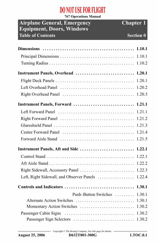
Chapter 1Airplane General, Emergency Equipment, Doors, WindowsTable of Contents Section 0
Copyright © The Boeing Company. See title page for details.
D632T001-300G 1.TOC.0.1
1.0 Airplane General, Emergency Equipment, Doors, Windows-Table of Contents
Dimensions . . . . . . . . . . . . . . . . . . . . . . . . . . . . . . . . . . . . . . . . . . 1.10.1
Principal Dimensions . . . . . . . . . . . . . . . . . . . . . . . . . . . . . . . . . . 1.10.1Turning Radius . . . . . . . . . . . . . . . . . . . . . . . . . . . . . . . . . . . . . . . 1.10.2
Instrument Panels, Overhead . . . . . . . . . . . . . . . . . . . . . . . . . . . 1.20.1
Flight Deck Panels . . . . . . . . . . . . . . . . . . . . . . . . . . . . . . . . . . . . 1.20.1Left Overhead Panel . . . . . . . . . . . . . . . . . . . . . . . . . . . . . . . . . . 1.20.2Right Overhead Panel . . . . . . . . . . . . . . . . . . . . . . . . . . . . . . . . . 1.20.3
Instrument Panels, Forward . . . . . . . . . . . . . . . . . . . . . . . . . . . . 1.21.1
Left Forward Panel . . . . . . . . . . . . . . . . . . . . . . . . . . . . . . . . . . . 1.21.1Right Forward Panel . . . . . . . . . . . . . . . . . . . . . . . . . . . . . . . . . . 1.21.2Glareshield Panel . . . . . . . . . . . . . . . . . . . . . . . . . . . . . . . . . . . . . 1.21.3Center Forward Panel . . . . . . . . . . . . . . . . . . . . . . . . . . . . . . . . . 1.21.4Forward Aisle Stand . . . . . . . . . . . . . . . . . . . . . . . . . . . . . . . . . . 1.21.5
Instrument Panels, Aft and Side . . . . . . . . . . . . . . . . . . . . . . . . . 1.22.1
Control Stand . . . . . . . . . . . . . . . . . . . . . . . . . . . . . . . . . . . . . . . . 1.22.1Aft Aisle Stand . . . . . . . . . . . . . . . . . . . . . . . . . . . . . . . . . . . . . . . 1.22.2Right Sidewall, Accessory Panel . . . . . . . . . . . . . . . . . . . . . . . . . 1.22.3Left, Right Sidewall, and Observer Panels . . . . . . . . . . . . . . . . . 1.22.4
Controls and Indicators . . . . . . . . . . . . . . . . . . . . . . . . . . . . . . . . 1.30.1
Push–Button Switches . . . . . . . . . 1.30.1Alternate Action Switches . . . . . . . . . . . . . . . . . . . . . . . . . . . 1.30.1Momentary Action Switches . . . . . . . . . . . . . . . . . . . . . . . . . 1.30.2
Passenger Cabin Signs . . . . . . . . . . . . . . . . . . . . . . . . . . . . . . . . 1.30.2Passenger Sign Selectors . . . . . . . . . . . . . . . . . . . . . . . . . . . . 1.30.2
August 25, 2006
767 Operations Manual
Copyright © The Boeing Company. See title page for details.
1.TOC.0.2 D632T001-300G
Airplane General, Emergency Equipment, Doors, Windows -Table of Contents
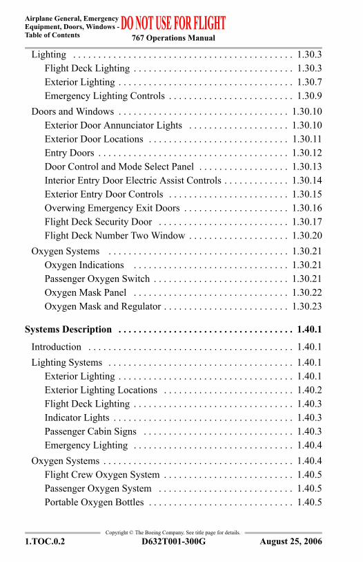
Lighting . . . . . . . . . . . . . . . . . . . . . . . . . . . . . . . . . . . . . . . . . . . . 1.30.3Flight Deck Lighting . . . . . . . . . . . . . . . . . . . . . . . . . . . . . . . . 1.30.3Exterior Lighting . . . . . . . . . . . . . . . . . . . . . . . . . . . . . . . . . . . 1.30.7Emergency Lighting Controls . . . . . . . . . . . . . . . . . . . . . . . . . 1.30.9
Doors and Windows . . . . . . . . . . . . . . . . . . . . . . . . . . . . . . . . . . 1.30.10Exterior Door Annunciator Lights . . . . . . . . . . . . . . . . . . . . 1.30.10Exterior Door Locations . . . . . . . . . . . . . . . . . . . . . . . . . . . . 1.30.11Entry Doors . . . . . . . . . . . . . . . . . . . . . . . . . . . . . . . . . . . . . . 1.30.12Door Control and Mode Select Panel . . . . . . . . . . . . . . . . . . 1.30.13Interior Entry Door Electric Assist Controls . . . . . . . . . . . . . 1.30.14Exterior Entry Door Controls . . . . . . . . . . . . . . . . . . . . . . . . 1.30.15Overwing Emergency Exit Doors . . . . . . . . . . . . . . . . . . . . . 1.30.16Flight Deck Security Door . . . . . . . . . . . . . . . . . . . . . . . . . . 1.30.17Flight Deck Number Two Window . . . . . . . . . . . . . . . . . . . . 1.30.20
Oxygen Systems . . . . . . . . . . . . . . . . . . . . . . . . . . . . . . . . . . . . 1.30.21Oxygen Indications . . . . . . . . . . . . . . . . . . . . . . . . . . . . . . . 1.30.21Passenger Oxygen Switch . . . . . . . . . . . . . . . . . . . . . . . . . . . 1.30.21Oxygen Mask Panel . . . . . . . . . . . . . . . . . . . . . . . . . . . . . . . 1.30.22Oxygen Mask and Regulator . . . . . . . . . . . . . . . . . . . . . . . . . 1.30.23
Systems Description . . . . . . . . . . . . . . . . . . . . . . . . . . . . . . . . . . . 1.40.1
Introduction . . . . . . . . . . . . . . . . . . . . . . . . . . . . . . . . . . . . . . . . . 1.40.1Lighting Systems . . . . . . . . . . . . . . . . . . . . . . . . . . . . . . . . . . . . . 1.40.1
Exterior Lighting . . . . . . . . . . . . . . . . . . . . . . . . . . . . . . . . . . . 1.40.1Exterior Lighting Locations . . . . . . . . . . . . . . . . . . . . . . . . . . 1.40.2Flight Deck Lighting . . . . . . . . . . . . . . . . . . . . . . . . . . . . . . . . 1.40.3Indicator Lights . . . . . . . . . . . . . . . . . . . . . . . . . . . . . . . . . . . . 1.40.3Passenger Cabin Signs . . . . . . . . . . . . . . . . . . . . . . . . . . . . . . 1.40.3Emergency Lighting . . . . . . . . . . . . . . . . . . . . . . . . . . . . . . . . 1.40.4
Oxygen Systems . . . . . . . . . . . . . . . . . . . . . . . . . . . . . . . . . . . . . . 1.40.4Flight Crew Oxygen System . . . . . . . . . . . . . . . . . . . . . . . . . . 1.40.5Passenger Oxygen System . . . . . . . . . . . . . . . . . . . . . . . . . . . 1.40.5Portable Oxygen Bottles . . . . . . . . . . . . . . . . . . . . . . . . . . . . . 1.40.5
August 25, 2006
767 Operations Manual
Airplane General, EmergencyEquipment, Doors, Windows -
Table of Contents
Copyright © The Boeing Company. See title page for details.
D632T001-300G 1.TOC.0.3
Doors and Windows . . . . . . . . . . . . . . . . . . . . . . . . . . . . . . . . . . . 1.40.5Flight Deck Security Door . . . . . . . . . . . . . . . . . . . . . . . . . . . 1.40.6Flight Deck Number Two Windows . . . . . . . . . . . . . . . . . . . . 1.40.7Passenger Entry Doors . . . . . . . . . . . . . . . . . . . . . . . . . . . . . . 1.40.8Passenger Entry Door and Slide Operation . . . . . . . . . . . . . . 1.40.9Escape Slide/Raft Deployed . . . . . . . . . . . . . . . . . . . . . . . . . 1.40.10Overwing Emergency Exit Doors . . . . . . . . . . . . . . . . . . . . . 1.40.10Evacuation Slides . . . . . . . . . . . . . . . . . . . . . . . . . . . . . . . . . 1.40.12Cargo Doors . . . . . . . . . . . . . . . . . . . . . . . . . . . . . . . . . . . . . 1.40.12
Flight Deck Seats . . . . . . . . . . . . . . . . . . . . . . . . . . . . . . . . . . . . 1.40.13Pilot Seat Adjustment . . . . . . . . . . . . . . . . . . . . . . . . . . . . . . 1.40.14
Emergency Equipment . . . . . . . . . . . . . . . . . . . . . . . . . . . . . . . . . 1.45.1
Introduction . . . . . . . . . . . . . . . . . . . . . . . . . . . . . . . . . . . . . . . . . 1.45.1Emergency Equipment . . . . . . . . . . . . . . . . . . . . . . . . . . . . . . . . . 1.45.1
Fire Extinguishers . . . . . . . . . . . . . . . . . . . . . . . . . . . . . . . . . . 1.45.1Miscellaneous Emergency Equipment . . . . . . . . . . . . . . . . . . 1.45.2Emergency Equipment Symbols . . . . . . . . . . . . . . . . . . . . . . . 1.45.3
Emergency Equipment Locations . . . . . . . . . . . . . . . . . . . . . . . . 1.45.4
EICAS Messages . . . . . . . . . . . . . . . . . . . . . . . . . . . . . . . . . . . . . . 1.50.1
Airplane General, Emergency Equipment, Doors, Windows EICAS Messages . . . . . . . . . . . . . . . . . . . . . . . . . . . . 1.50.1
Access Doors . . . . . . . . . . . . . . . . . . . . . . . . . . . . . . . . . . . . . 1.50.1Cargo Doors . . . . . . . . . . . . . . . . . . . . . . . . . . . . . . . . . . . . . . 1.50.1Entry Doors . . . . . . . . . . . . . . . . . . . . . . . . . . . . . . . . . . . . . . . 1.50.2Overwing Emergency Exit Doors . . . . . . . . . . . . . . . . . . . . . 1.50.2Emergency Lights . . . . . . . . . . . . . . . . . . . . . . . . . . . . . . . . . . 1.50.2Oxygen System . . . . . . . . . . . . . . . . . . . . . . . . . . . . . . . . . . . . 1.50.2
August 25, 2006
767 Operations Manual
Copyright © The Boeing Company. See title page for details.
1.TOC.0.4 D632T001-300G
Airplane General, Emergency Equipment, Doors, Windows -Table of Contents
IntentionallyBlank
August 25, 2006
767 Operations Manual
Chapter 1Airplane General, Emergency Equipment, Doors, WindowsDimensions Section 10
Copyright © The Boeing Company. See title page for details.
D632T001-300G 1.10.1
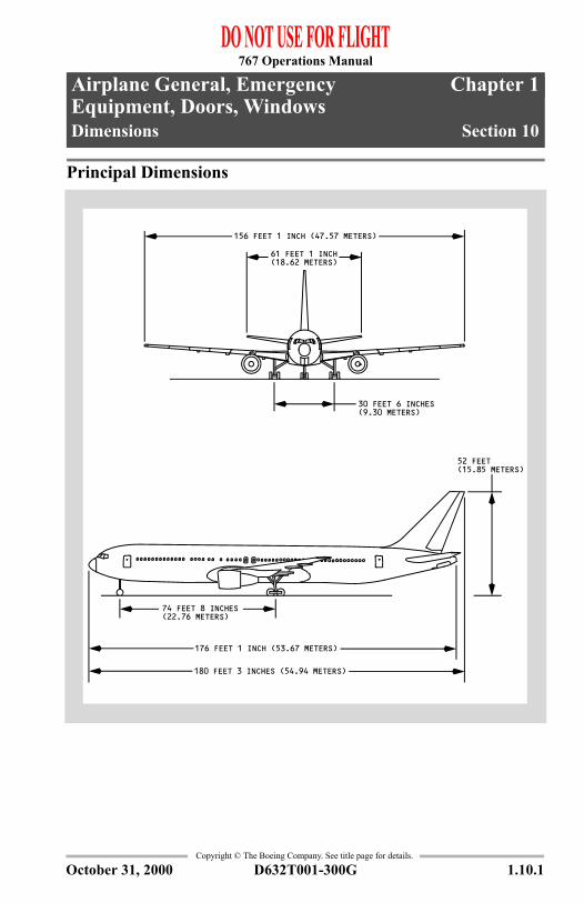
1.10 Airplane General, Emergency Equipment, Doors, Windows-DimensionsPrincipal Dimensions
30 FEET 6 INCHES(9.30 METERS)
156 FEET 1 INCH (47.57 METERS)
52 FEET
74 FEET 8 INCHES(22.76 METERS)
176 FEET 1 INCH (53.67 METERS)
61 FEET 1 INCH(18.62 METERS)
180 FEET 3 INCHES (54.94 METERS)
(15.85 METERS)
October 31, 2000
767 Operations Manual
Airplane General, Emergency Equipment, Doors, Windows -Dimensions
Copyright © The Boeing Company. See title page for details.
1.10.2 D632T001-300G
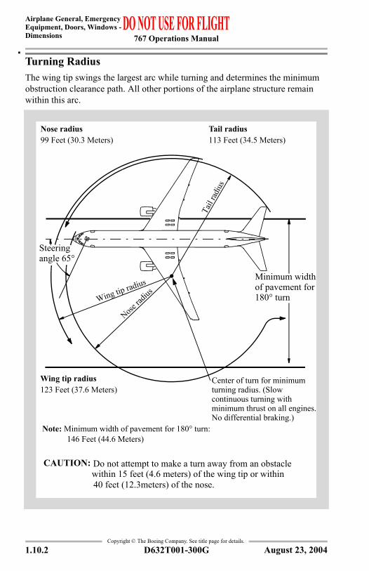
Turning RadiusThe wing tip swings the largest arc while turning and determines the minimum obstruction clearance path. All other portions of the airplane structure remain within this arc.
Nose radius99 Feet (30.3 Meters)
Tail radius113 Feet (34.5 Meters)
Center of turn for minimum turning radius. (Slow continuous turning with minimum thrust on all engines. No differential braking.)
Wing tip radius123 Feet (37.6 Meters)
Note: Minimum width of pavement for 180° turn:146 Feet (44.6 Meters)
Steering angle 65°
Minimum width of pavement for 180° turnWing tip radius
Nose ra
dius
Tail
radi
us
Do not attempt to make a turn away from an obstacle within 15 feet (4.6 meters) of the wing tip or within
CAUTION:
40 feet (12.3meters) of the nose.
August 23, 2004
767 Operations Manual
Chapter 1Airplane General, Emergency Equipment, Doors, WindowsInstrument Panels, Overhead Section 20
Copyright © The Boeing Company. See title page for details.
D632T001-300G 1.20.1
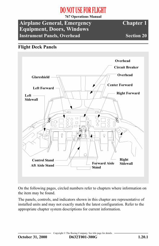
1.20 Airplane General, Emergency Equipment, Doors, Windows-Instrument Panels, OverheadFlight Deck Panels
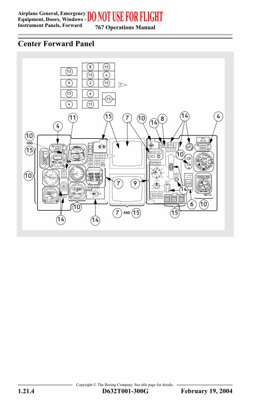
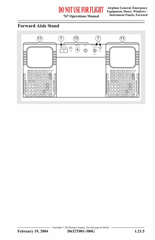
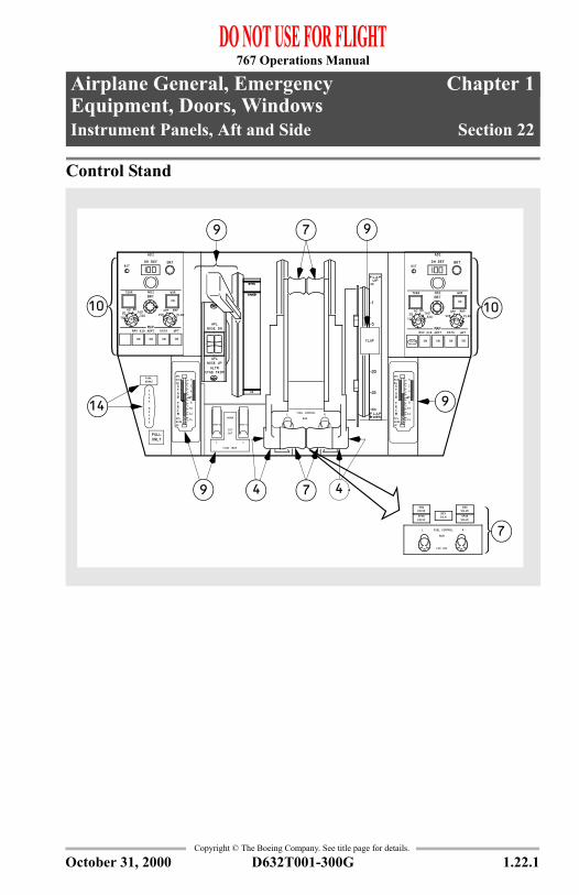
On the following pages, circled numbers refer to chapters where information on the item may be found.The panels, controls, and indicators shown in this chapter are representative of installed units and may not exactly match the latest configuration. Refer to the appropriate chapter system descriptions for current information.
Forward Aisle Stand
Left Forward
Glareshield
Aft Aisle Stand
Left Sidewall
Overhead
Center Forward
Right Forward
Overhead
Circuit Breaker
Right Sidewall
Control Stand
October 31, 2000

767 Operations Manual
Airplane General, Emergency Equipment, Doors, Windows -Instrument Panels, Overhead
Copyright © The Boeing Company. See title page for details.
1.20.2 D632T001-300G
Left Overhead Panel
ONONON
ON
OFF
ON
OFF
RLNOSE GEARWING
LANDING
ON
TAXI RUNWAY TURNOFF
OFF OFF
ON
OFFOFF RL
ON
PUMPS
DNAMED
C
YRAMIRP
ENG R
ELEC
ONOFFAUTO
ONOFFAUTO
OVHT
PRESS
ON
OVHT
PRESS
ON
OVHT
PRESS
ON
OVHT
QTY
PRESS SYS
QTY
PRESS SYS
QTY
PRESS SYS
YRAMIRP ENG
LHYD
1-ELEC-2
PRESS
ON
OVHT
PRESS
AIR
OVHT
PRESS
DNAMED
ELEC
ONOFFAUTO
OVHT
PRESS
PRESS
ON
PRESS
ON
FWD
AFT
C PUMPS
FWD
AFT
R PUMPSCROSSFEED
FUELL PUMPS
SSERP
ON
SSER RIGHTLEFTP
ON
VALVE
PRESS
ON
PRESS
ON
CONFIG FUEL
COCKPIT VOICE RECORDER600 OHMSHEADSET
ERASETEST
RCL
DSPL SEL
DC FAIL
ON DC
FAULT
ALIGN
ATTNAV
OFF
ALIGN
DC FAIL
ON DC
FAULT
ALIGN
ATTNAV
OFF
ALIGN
6E
4W
2N
DC FAIL
ON DC
FAULT
ALIGN
ATTNAV
NW
PPOS WIND
TK/GS HDG
SYS DSPL
RLC
5H
8S 97
31
0 CLRENT
BRT
IRS MODE SEL
OFF
ALIGN
WINGPOSITIONWHITERED
COLLISIONANTI
R
FFO
ON
LGEN DRIVE DISC
L BUS R BUSRL
UTILITY BUS
BUS TIEBUS TIE
DRIVE DRIVE
AUTO
ISLN
FFO
ON
OFFBUS
AVAIL
ON
OFFBUS
FFO
ON
APU GEN EXT PWR
ON
OFF
ON
OFF
AUTO
ISLN
CONTGEN R
CONTGEN
L
FAULT
APUSTART
ONOFF
RUN
ON
PANEL/FLOOD
AISLE STANDGLARESHIELDLT OVRD
LBS X 1000
RAM AIR TURB
GND
ENG STARTBOTH
1 2RL
FLT
CONTOFF
AUTOGND
FLT
CONTOFF
AUTO
VALVE
PRESS
UNLKD
VALVERL
INOP
YAW DAMPER
ON
INOP
ON
AUTOSPDBRK
ACCESS
L AOA
CARGODOORS
RUDDER
SPOILERS
R AUXPITOT
F OPITOT
EMER
UNSCHEDSTAB TRIM
STABTRIM
L AUXPITOT
ENTRYDOORS
ANTISKID AILLOCK
DOORS
PITOTCAPT
DOORS
RATIO
TAT
R AOA
ON
OFFDISCH
AUTOOFF
BAT STBY POWER
OFF
BAT
ARMED
EMER LIGHTS PASS OXY
UNARMED
OFF
ON ON
1
FUEL TEMP °C
RCL
TOTAL QTY
FUEL QTY
INOP
ON
R
INOP
ON
CONTENGELEC
L
1
3
5
67
9
11
1213
1
6 7
7
13
ANTISKID
ON
OFF
ON
L-ENG-R
VALVEVALVE
ON
VALVEL
WING ANTI-ICE
RON
VALVE
ICING
RAIN REPELLENT WIPER
HIGH
LOW
OFFRL
1111
14
3 3 3 3
3 3 3
9 9 9
9 9 9
1
1
14
October 31, 2000

767 Operations Manual
Airplane General, EmergencyEquipment, Doors, Windows -Instrument Panels, Overhead
Copyright © The Boeing Company. See title page for details.
D632T001-300G 1.20.3
Right Overhead Panel
1
2
3
1
2
2
5
EQUIP COOLING
LDG .125 PSI
AUTOSTBY
OVRD
PRESS DIFFLIMIT: T/O &
CABIN
COOLINGNO
ALTITUDE VALVE
SMOKE
OVHT
ON
INOP
L RSIDE FWD
WINDOW HEAT
ON
INOP
ON
INOP
ON
INOP
SIDEFWD
FWD AFT BULK
CARGO HEAT
ON
OVHT
ON
OVHT
ON
OVHT
CABIN
RATEALTDIFF PSIFT X1000
FPM X1000
02
46
8
100 2
46
810152025 1 2
210
AUTO
ONOFF
NO SMOKING SEATBELTSAUTO
ONOFF
PASS SIGNS
MODE SELECTAUTO INOP
AUTO 2AUTO 1 MAN
LDG ALT
MIN MAXDESCEND
CLIMBMANUAL AUTO RATEVALVE
OP
CL
CABIN ALTITUDE CONTROL
03400
VIDEO ON
INOP INOP INOP
OVHTOVHT
VALVE
EVLAV
L ISLN R ISLN
C ISLN
APUL ENG R ENG
BLEED
LEAKDUCT
VALVE
FFO
EVLAV
FFO
ADP
KAEL
TCUD
BLEED
LEAKDUCT
PSIPRESSDUCT
020
8060
YBTS
YBTS
C
FLT DK
WC
WMAN
C
RESETR PACK
RESETL PACK
AUTO
L � RECIRC FAN � RTRIM AIR
WOFFC
OFF WOFFCW
AUTOAFT CAB
AUTOMID CAB
AUTOFWD CAB
OFFOFFPACKPACK
INOPINOP
INOP
ONON
INOP
ON
OFF INOP
W
C
NAUTO
OFF
W
C
NAUTO
OFF
INOP
SELCAL
CALL
PAIN
USE
CABIN CALL
FWDGND
L C R
MID AFT ALERT
CALL
CALLCALLCALLCALLCALL
VHF
FLTINTCALL
CABIN
CALL CALL CALL
HFINOP
INOP
5
DIM BRT
UNLKD DENYAUTO
ON FAILLOCK
UNLKAUTO
IND LTS
LOGO
TEST
FLT DK DOOR
CKT BKR
OFF
OVHD PANEL
OFF
DOME
OFF
February 19, 2004

767 Operations Manual
Airplane General, Emergency Equipment, Doors, Windows -Instrument Panels, Overhead
Copyright © The Boeing Company. See title page for details.
1.20.4 D632T001-300G
IntentionallyBlank
October 31, 2000
767 Operations Manual
Chapter 1Airplane General, Emergency Equipment, Doors, WindowsInstrument Panels, Forward Section 21
Copyright © The Boeing Company. See title page for details.
D632T001-300G 1.21.1
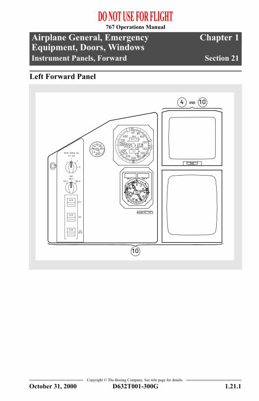
1.21 Airplane General, Emergency Equipment, Doors, Windows-Instrument Panels, ForwardLeft Forward Panel
AND
VOR
DME-RDME-L
4
10
10
ALTN
ALTN
ALTN
EFI
IRS
AIRDATA
FMC-RCDU-LFMC-LNAV
FLT DIR
R
CL
INSTR SOURCE SEL
A C H
INOP
A S
M O
M
KNOTS
MACH
ADF INOP
TAXIKNOTS
051015 20
25
October 31, 2000
767 Operations Manual
Airplane General, Emergency Equipment, Doors, Windows -Instrument Panels, Forward
Copyright © The Boeing Company. See title page for details.
1.21.2 D632T001-300G
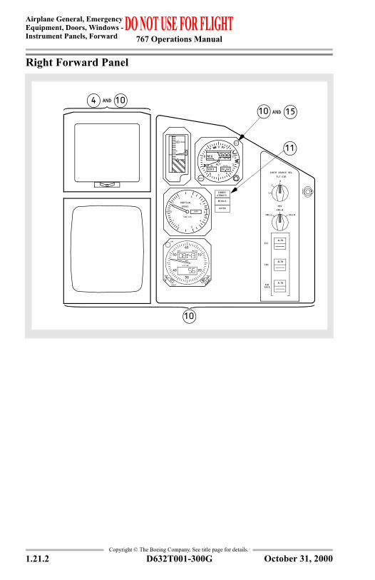
Right Forward Panel
AND
AND
OUTER
MIDDLE
INNER/AIRWAYS
1000 FPM
.5
OFF
1 2
4
0
VERTICAL SPEED
1 2
4
6
.5
1013
ALT
BARO
MB IN.HG
4
ALT 3
6
8
90 1
2
5
9229
NEG
100
0
4
11
10 1510
10
HLDYMSM
HSD
RUN RUN
HLD
RESET
DAY MO/YR
GMT
ET/CHR
CHR
40
50
60
30
20
10
L
C
R
CDU-R
INSTR SOURCE SEL
FLT DIR
ALTN
AIR
EFI
IRS
DATA
ALTN
ALTN
FMC-L
FMC-R
NAV
October 31, 2000
767 Operations Manual
Airplane General, EmergencyEquipment, Doors, Windows -
Instrument Panels, Forward
Copyright © The Boeing Company. See title page for details.
D632T001-300G 1.21.3
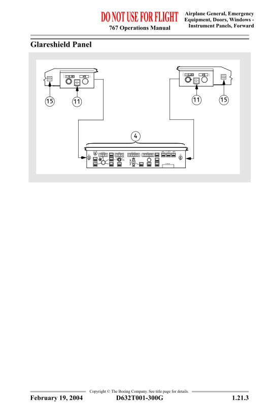
Glareshield Panel
F/D
IAS/MACHA/T ARM
OFF
SPD
ON
OFF
SEL
L NAV
V NAV
FL CH
HDG
5 25
BANKLIMIT
AUTO SEL
HOLD
VERT SPD
UP
DN
V/S
ALT
HOLD
LOC
APP
CMD CMDCMD
A/P ENGAGEL C R
DISENGAGE
OFF
F/DON
N1
0001 70 03207202 0
SRC
VOR/DME
MAN
AUTO
QERF
SRC
VOR/DME
MAN
AUTO
QERF
CAUTION
WARNING
CAUTION
WARNING
4
11 151115
B/CRS
February 19, 2004
767 Operations Manual
Airplane General, Emergency Equipment, Doors, Windows -Instrument Panels, Forward
Copyright © The Boeing Company. See title page for details.
1.21.4 D632T001-300G
Center Forward Panel
BRAKESOURCE
RESERVE
1000 FPM.5
.5
OFF
1 24
0
VERTICAL SPEED
1 2
4
6
GMT
ET/CHR
RESET
HLDRUN
FSSSHLDRUN
40
50
60
10
20
30
MIDDLE
INNER/AIRWAYS
AND
FLAP LIMIT IAS
DN
UP RETRACT 270K
OFF
TE
ALTN ALTN
LE
OFF
DN
REG
MACH
0
5
4KNOTS
37
2 4
SELCAL
FLAP GEAREXTEND250K-.75M
0
IAS
60 80100120
140
160180200220
240250
300350400
KNOTS
4
3
MAXAUTO
21
DISARM
OFF
AUTOBRAKES
AUTO BRAKES
RTO
100
0
8
15
2
4
11
15
4
15
154
19
15
AUTOLAND STATUS
P/RST1
2
TESTNO LAND 3
LAND 3
AUTOLAND STATUS
P/RST1
2
TEST
NO LAND 3
LAND 34
3
2 1
0
BRAKE
PSIXPRESS
1000NOSE
SKIDTAILD
OORS
GEAR
BRAKETEMP
WHL WELL FIRE
LEFT RIGHT
CON
TOGA
CRZ
CLB
TEMP SEL
1 2
NORM
TRUE
HDG REF
LEADING EDGE
TRAILING EDGE
DME-L DME-R
CAUTION
CANCEL RECALL
B/CRS
ILSOFFMB IN.HG
ALT
1013
BARO
4
ALT 3
8
9 0
2
5
9229
OFF
6
1
OUTER
BKS & STRG
ON
VALVE
ALT
BARO
1013IN. HG
92294
56
7
8
90
1
2
3MB
1114.
650
1055.
1114.
650
1055.
N1
EGT
ONAUTO
N2
L ENGOIL PRESS
R ENGOIL PRESS
ALTN FLAPS5
15
20
25NORM
UP
1
190K
195K
220K240K 210K
162K
UP
1
20
155
FLAPS
3025
LOCK OVRD
EXTENDED270K-.82M
EXTEND OR
PROXG/S INHB
GND ALTALERT
A/TDISC
AUTOPILOT
FMC
SPEEDBRAKES
CABIN ALT
FIRE CONFIG
OVSPD
A/PDISCPULL UP
WINDSHEAR 11
15
AND
47 8
9
11 1014
15
4
7
71010
10
10
14
141415
15
15
CHR
TAS
SAT
KT
°C
FLT INSTR
BUS PWR
ALTN
GND PROX
OVRD
FLAP OVRD
OVRD OVRD
TERR OVRDGEAR OVRD
14
10
ADF INOP
6
February 19, 2004
767 Operations Manual
Airplane General, EmergencyEquipment, Doors, Windows -
Instrument Panels, Forward
Copyright © The Boeing Company. See title page for details.
D632T001-300G 1.21.5
Forward Aisle Stand
MENU
INTC
MENU
INTC
RECORDEVENT
RESETMAX IND
PULL
RBOTHL
THRUST REF SETBRT
RAUTOL
COMPUTER
ENGINE STATUS
DISPLAY
PROG
K
X
-+0Ñ
987
654
321
RLC/LDEZ
YWU
TSRQP
ONML
JIHGF
EDCBA
CLB
PAGENEXT
PAGEPREV
FIX
HOLDARRDEPLEGSDIR
BRTDESCRZRTEREF
INIT
PROG
K
X
-+0Ñ
987
654
321
RLC/LDEZ
YWVU
TRQP
ONML
JIHGF
EDCBA
CLB
PAGENEXT
PAGEPREV
FIX
HOLDARRDEPLEGSDIR
BRTDESCRZRTEREF
INIT
S
SP
V
SP
7 1115 711
LIAF
SPY
D
LIAF
SPY
D
TSFO
GSM
TSFO
GSM
EXEC EXEC
February 19, 2004
767 Operations Manual
Airplane General, Emergency Equipment, Doors, Windows -Instrument Panels, Forward
Copyright © The Boeing Company. See title page for details.
1.21.6 D632T001-300G
IntentionallyBlank
February 19, 2004
767 Operations Manual
Chapter 1Airplane General, Emergency Equipment, Doors, WindowsInstrument Panels, Aft and Side Section 22
Copyright © The Boeing Company. See title page for details.
D632T001-300G 1.22.1
1.22 Airplane General, Emergency Equipment, Doors, Windows-Instrument Panels, Aft and SideControl Stand
P
EKA
K
RB
RA
BRAKEPARK
STAB TRIM
NORM
OUTCUT
CL
RUNRL FUEL CONTROL
FLAP
STAB TRIMALTN
NOSE UPAPL
NOSE DNAPL
ONLYPULL
979
1010
7
79 4 4
14 9UP
A
I
0DN
10
NOSE
M14
APL
B
RT
TS
NOSEAPL
2
4
12
8
6
FFO
VALVEENG
VALVESPAR
VALVEENG
VALVESPAR
CUT OFF
RUN
RL FUEL CONTROL
ISLNREV
UP
A
I
0DN
10
NOSE
M14
APL
B
RT
TS
NOSEAPL
2
4
12
8
6
FFO
ADI
BRTHSI
MAP
BRTDH REF
20MAP
320160
8040
10VOR
APP
WPT
CTRTFC
NAV AID ARPT DATA
ONONONON
ON
WXRTERR
RST
INOP
PLAN
ADI
BRTHSI
MAP
BRTDH REF
20MAP
320160
8040
10VOR
APP
WPT
CTRTFC
NAV AID ARPT DATA
ONONONON
ON
WXRTERR
RST
PLAN
October 31, 2000
767 Operations Manual
Airplane General, Emergency Equipment, Doors, Windows -Instrument Panels, Aft and Side
Copyright © The Boeing Company. See title page for details.
1.22.2 D632T001-300G
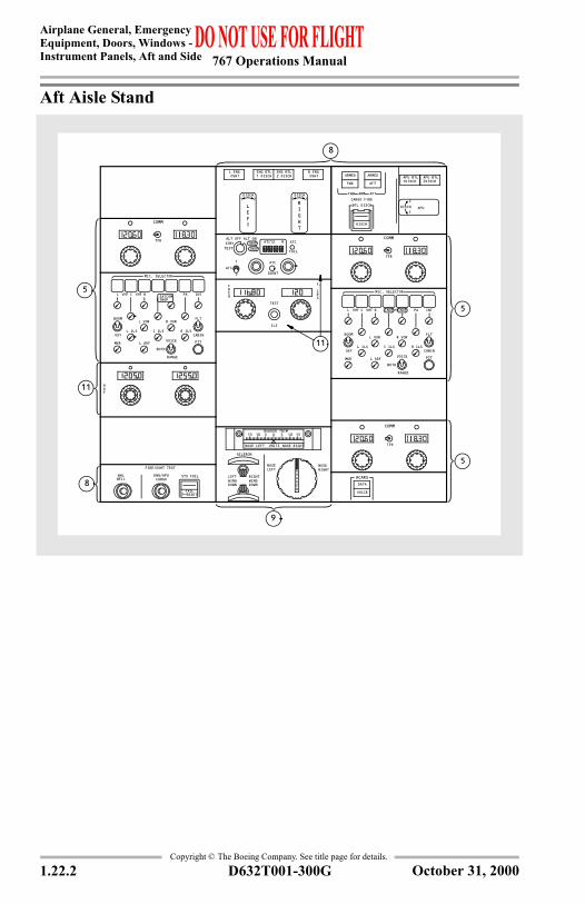
Aft Aisle Stand
5
8
5
8
11
DISCH1 2
DISCH21
L ENG OVHT
R ENG OVHT
ENG BTL1 DISCH
ENG BTL2 DISCH
9
PA INT
L ILS
MKR
L VOR
L ADF
FLT
CABIN
MIC. SELECTOR
PTT
L VHF
RANGE
VOICE
BOTH
C ILS
R VOR
R ILS
BOOM
OXY
C VHF R
PA INT
L ILS
MKR
L VOR
L ADF
FLT
CABIN
MIC. SELECTOR
PTT
L VHF
RANGE
VOICE
BOTH
C ILS
R VOR
R ILS
BOOM
OXY
C VHF R HF
AILERON
LEFTWINGDOWN
RIGHTWINGDOWN
NOSELEFT
NOSERIGHT
RUDDER TRIM
NOSE LEFT NOSE RIGHTUNITS
0510 5 10 1515
FAILP-RESET
FIRE/OVHT TEST
SYS FAILENG/APU CARGOWELL
WHL
LEFT
RIGHT
TESTSRC
F.
ILS
QERF
11
FDA
INOP INOP
INOP
ED
R
DUR
ATC
TESTSTBY ATC12 RALT OFF ALT ON
IDENT
ATC
FAIL
1
2
ATC
TFR
COMM
TFR
COMM
2
1DISCH
DISCH2APU BTL
DISCH1APU BTLARMEDARMED
DISCH
APU
AFTFWD
ARMFWD AFTCARGO FIREBTL DISCH
INOPINOP
TFR
COMM
5
DATA
VOICE
ACARS
SATCOM
October 31, 2000
767 Operations Manual
Airplane General, EmergencyEquipment, Doors, Windows -
Instrument Panels, Aft and Side
Copyright © The Boeing Company. See title page for details.
D632T001-300G 1.22.3
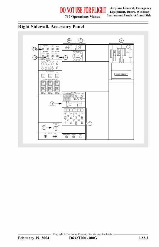
Right Sidewall, Accessory Panel
15
12
FIELDOFF
C
ON
OFF
GEN FIELD MAN RESET
FLT CONTROL SHUTOFF - GND USE ONLY
TAIL
WING
APU
R
ON
OFF
FIELDOFF
R
ON
OFF
ON
OFF
FIELDOFF
L
OFF
R
ON
OFF
WING
L R
TAIL
ON
APUHOURS
2
APUL R TEST 1 SLIDE TEST 2SPOILER
2
TESTR 1
SQUIB TESTCARGO ENG
FWD AFT L
EMER ESCAPE
NORMVENT
BULK CARGO HEAT
OFFOFF
NORMON
FLT RCDR SERV INTPH
TEST
ON
PERFAPU
CONFMCDP
ENGEXCD
EICAS MAINTDISPLAY SELECT AUTO MANEVENT
READ
TESTREC ERASE
ECSMSG
ELECHYD
RESERVE BRAKES & STRGRESET/DISABLE
NORM
C HYD SYS
ISLN
INT
L ILS
MKR
L VOR
L ADF
MIC. SELECTOR
PTT
RANGE
VOICE
BOTH
C ILS
R VOR
R ILS
BOOM
OXY
VHFL
FLT
CABIN
C PAL HFVHF R R
BOOM MIC/HEADSET HEADPHONE HANDMIC
13
5
TEST OXYGENMASK
RESET
PUSH100%N
SMOKE GOGGLES
LIGHTINGMAP
OFF
PANEL
FUEL QTY
WINGANTI ICE
AIR DATA COMPTR CONFIG
TEST
T/O
WINDOW/PROBE HEAT
GND PROX
LDG
YAW DMPRL
R
EQUIP COOL
STALL
L
R
R
L DUCT LEAK
INOP
10 5 1
HYD GEN 6
February 19, 2004
767 Operations Manual
Airplane General, Emergency Equipment, Doors, Windows -Instrument Panels, Aft and Side
Copyright © The Boeing Company. See title page for details.
1.22.4 D632T001-300G
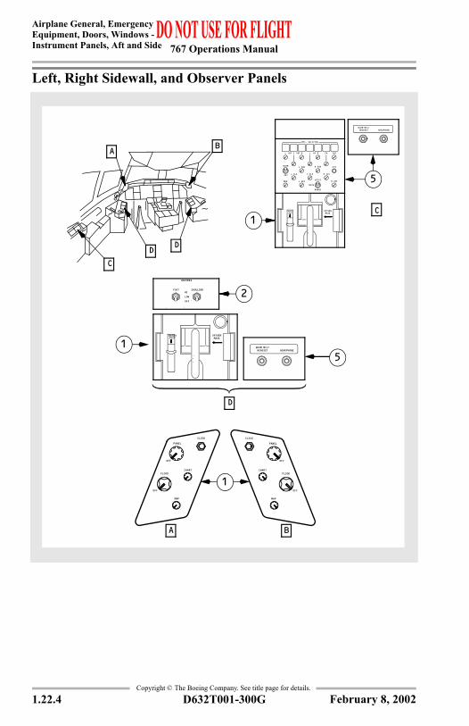
Left, Right Sidewall, and Observer Panels
B
A B
C
CD
D
A
OFF
OFF
CLOCK
PANEL
CHARTFLOOD
MAP
OFF
OFF
CLOCK
PANEL
CHARTFLOOD
MAP
D
HEATERS
FOOT
LOW
HI
OFF
SHOULDER
OXYGEN MASK
RESETTEST
BOOM MIC/ HEADSET HEADPHONE
OXYGEN MASK
RESETTEST
PAL VHF C R HF INT
L ILS
MKR
L VOR
L ADF
MIC. SELECTOR
PTT
RANGE
VOICE
BOTH
C ILS
R VOR
R ILS
BOOM
OXY
R ADF
BOOM MIC/ HEADSET HEADPHONE
VHF L R
1
2
51
1
5
February 8, 2002
767 Operations Manual
Chapter 1Airplane General, Emergency Equipment, Doors, WindowsControls and Indicators Section 30
Copyright © The Boeing Company. See title page for details.
D632T001-300G 1.30.1
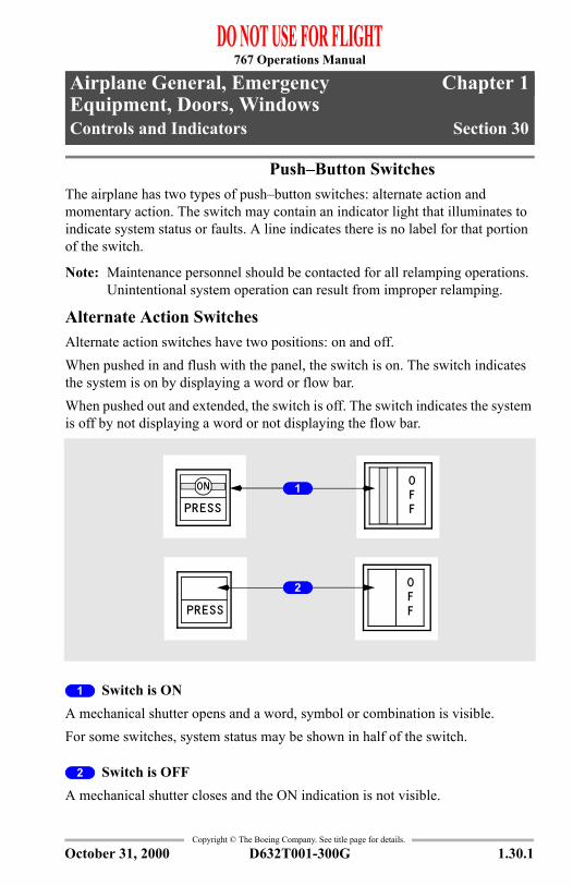
1.30 Airplane General, Emergency Equipment, Doors, Windows-Controls and Indicators Push–Button SwitchesThe airplane has two types of push–button switches: alternate action and momentary action. The switch may contain an indicator light that illuminates to indicate system status or faults. A line indicates there is no label for that portion of the switch.
Note: Maintenance personnel should be contacted for all relamping operations. Unintentional system operation can result from improper relamping.
Alternate Action SwitchesAlternate action switches have two positions: on and off.When pushed in and flush with the panel, the switch is on. The switch indicates the system is on by displaying a word or flow bar.When pushed out and extended, the switch is off. The switch indicates the system is off by not displaying a word or not displaying the flow bar.
1 Switch is ONA mechanical shutter opens and a word, symbol or combination is visible.For some switches, system status may be shown in half of the switch.
2 Switch is OFFA mechanical shutter closes and the ON indication is not visible.
ON
PRESS
OFF
PRESS
OFF
2
1
October 31, 2000
767 Operations Manual
Airplane General, Emergency Equipment, Doors, Windows -Controls and Indicators
Copyright © The Boeing Company. See title page for details.
1.30.2 D632T001-300G
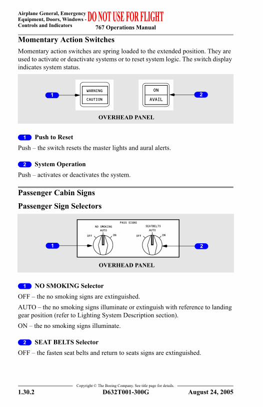
Momentary Action SwitchesMomentary action switches are spring loaded to the extended position. They are used to activate or deactivate systems or to reset system logic. The switch display indicates system status.
1 Push to ResetPush – the switch resets the master lights and aural alerts.
2 System OperationPush – activates or deactivates the system.
Passenger Cabin Signs
Passenger Sign Selectors
1 NO SMOKING SelectorOFF – the no smoking signs are extinguished.AUTO – the no smoking signs illuminate or extinguish with reference to landing gear position (refer to Lighting System Description section).ON – the no smoking signs illuminate.
2 SEAT BELTS SelectorOFF – the fasten seat belts and return to seats signs are extinguished.
OVERHEAD PANEL
WARNING
CAUTION AVAIL
ON21
PASS SIGNS
OFF ON
AUTOSEATBELTSNO SMOKING
OFF ONAUTO
OVERHEAD PANEL
1 2
August 24, 2005
767 Operations Manual
Airplane General, EmergencyEquipment, Doors, Windows -
Controls and Indicators
Copyright © The Boeing Company. See title page for details.
D632T001-300G 1.30.3
AUTO – the fasten seat belts and return to seats signs illuminate or extinguish with reference to landing gear or flap position (refer to Lighting System Description section).ON –the fasten seat belts and return to seats signs illuminate.
Note: Anytime passenger oxygen is deployed, the cabin signs revert to the following (regardless of selector position):
• No Smoking Illuminated• Fasten Seat Belts Illuminated• Return to seats extinguish if the cabin altitude is above 10,000 ft. and
passenger oxygen is on
Lighting
Flight Deck LightingLight Override Switch
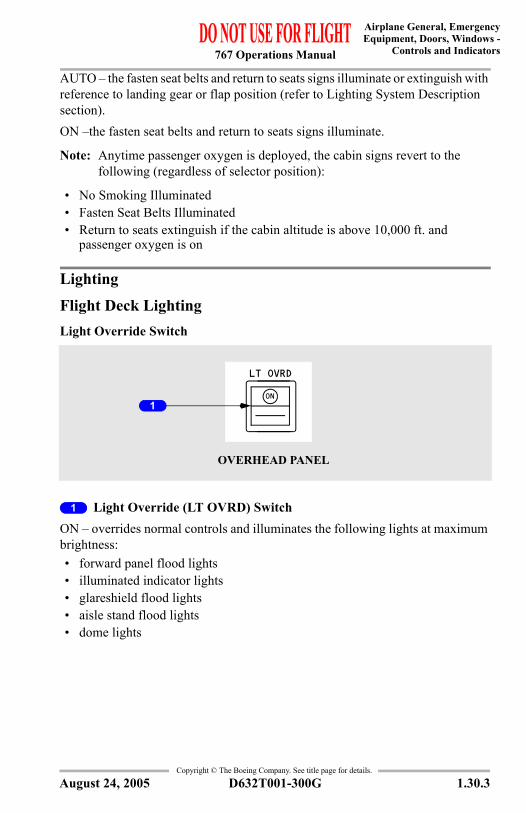
1 Light Override (LT OVRD) SwitchON – overrides normal controls and illuminates the following lights at maximum brightness:• forward panel flood lights• illuminated indicator lights• glareshield flood lights• aisle stand flood lights• dome lights
LT OVRD
ON
OVERHEAD PANEL
1
August 24, 2005
767 Operations Manual
Airplane General, Emergency Equipment, Doors, Windows -Controls and Indicators
Copyright © The Boeing Company. See title page for details.
1.30.4 D632T001-300G
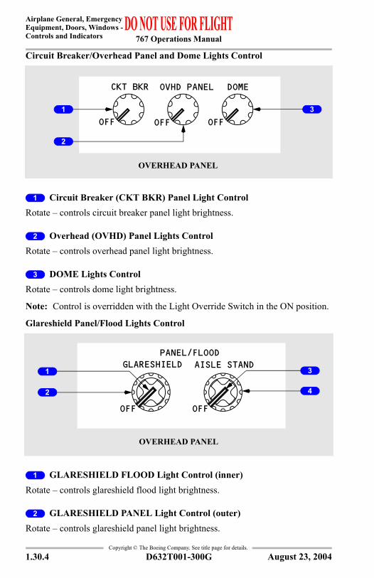
Circuit Breaker/Overhead Panel and Dome Lights Control
1 Circuit Breaker (CKT BKR) Panel Light ControlRotate – controls circuit breaker panel light brightness.
2 Overhead (OVHD) Panel Lights ControlRotate – controls overhead panel light brightness.
3 DOME Lights ControlRotate – controls dome light brightness.
Note: Control is overridden with the Light Override Switch in the ON position.
Glareshield Panel/Flood Lights Control
1 GLARESHIELD FLOOD Light Control (inner)Rotate – controls glareshield flood light brightness.
2 GLARESHIELD PANEL Light Control (outer)Rotate – controls glareshield panel light brightness.
OFF
CKT BKR OVHD PANEL DOME
OFFOFF
OVERHEAD PANEL
2
1 3
OVERHEAD PANEL
GLARESHIELD AISLE STANDPANEL/FLOOD
OFFOFF
3
4
1
2
August 23, 2004
767 Operations Manual
Airplane General, EmergencyEquipment, Doors, Windows -
Controls and Indicators
Copyright © The Boeing Company. See title page for details.
D632T001-300G 1.30.5
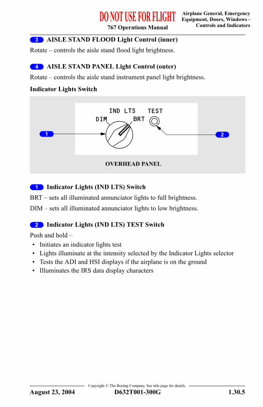
3 AISLE STAND FLOOD Light Control (inner)Rotate – controls the aisle stand flood light brightness.
4 AISLE STAND PANEL Light Control (outer)Rotate – controls the aisle stand instrument panel light brightness.
Indicator Lights Switch
1 Indicator Lights (IND LTS) SwitchBRT – sets all illuminated annunciator lights to full brightness.DIM – sets all illuminated annunciator lights to low brightness.
2 Indicator Lights (IND LTS) TEST SwitchPush and hold – • Initiates an indicator lights test• Lights illuminate at the intensity selected by the Indicator Lights selector• Tests the ADI and HSI displays if the airplane is on the ground• Illuminates the IRS data display characters
TESTBRTDIM
IND LTS
OVERHEAD PANEL
1 2
August 23, 2004
767 Operations Manual
Airplane General, Emergency Equipment, Doors, Windows -Controls and Indicators
Copyright © The Boeing Company. See title page for details.
1.30.6 D632T001-300G
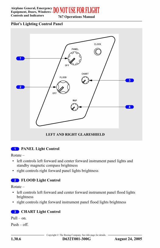
Pilot’s Lighting Control Panel
1 PANEL Light ControlRotate – • left controls left forward and center forward instrument panel lights and
standby magnetic compass brightness• right controls right forward panel lights brightness
2 FLOOD Light ControlRotate – • left controls left forward and center forward instrument panel flood lights
brightness• right controls right forward instrument panel flood lights brightness
3 CHART Light ControlPull – on.Push – off.
OFF
OFF
CLOCK
PANEL
CHARTFLOOD
MAP
3
LEFT AND RIGHT GLARESHIELD
1
2
4
August 24, 2005
767 Operations Manual
Airplane General, EmergencyEquipment, Doors, Windows -
Controls and Indicators
Copyright © The Boeing Company. See title page for details.
D632T001-300G 1.30.7
Rotate – adjusts chart light brightness.
4 MAP Light ControlPull – on.Push –off.Rotate – adjusts map light brightness.
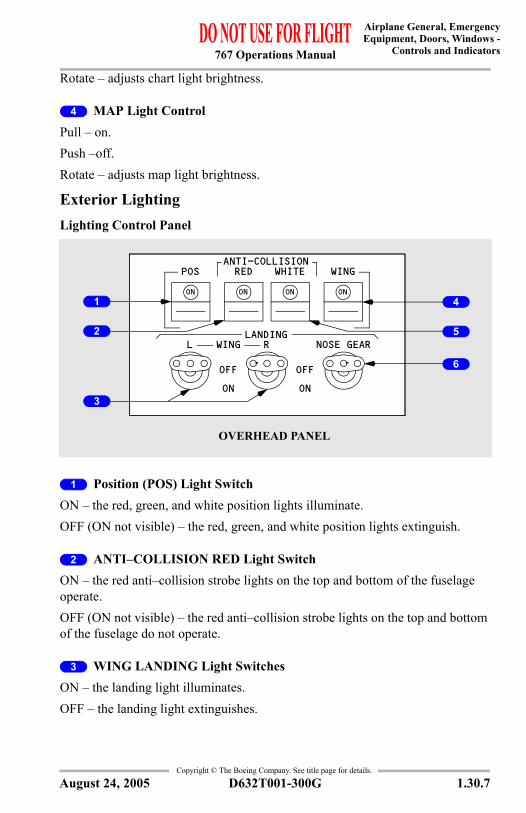
Exterior LightingLighting Control Panel
1 Position (POS) Light Switch ON – the red, green, and white position lights illuminate.OFF (ON not visible) – the red, green, and white position lights extinguish.
2 ANTI–COLLISION RED Light Switch ON – the red anti–collision strobe lights on the top and bottom of the fuselage operate.OFF (ON not visible) – the red anti–collision strobe lights on the top and bottom of the fuselage do not operate.
3 WING LANDING Light Switches ON – the landing light illuminates.OFF – the landing light extinguishes.
OVERHEAD PANEL
ANTI-COLLISIONWHITEREDPOS WING
L WINGLANDING
R
ON
OFF
ON
OFF
NOSE GEAR
ONON ONON4
5
6
1
2
3
August 24, 2005
767 Operations Manual
Airplane General, Emergency Equipment, Doors, Windows -Controls and Indicators
Copyright © The Boeing Company. See title page for details.
1.30.8 D632T001-300G
4 WING Light Switch ON – the wing leading edge illumination lights illuminate.OFF – the wing leading edge illumination lights extinguish.
5 ANTI–COLLISION WHITE Light SwitchON – the white anti–collision strobe lights on tips of each wing operate.OFF (ON not visible) – the white anti–collision strobe lights on tips of each wing do not operate.
6 NOSE GEAR LANDING Light SwitchON – the landing lights illuminate.OFF – the landing lights extinguish.
Note: The nose gear landing lights do not illuminate when the nose landing gear is not down and locked.
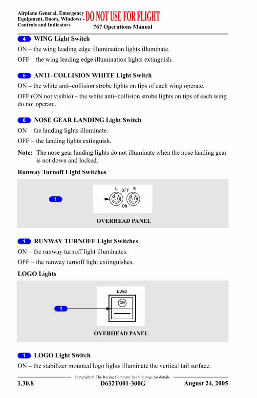
Runway Turnoff Light Switches
1 RUNWAY TURNOFF Light SwitchesON – the runway turnoff light illuminates.OFF – the runway turnoff light extinguishes.
LOGO Lights
1 LOGO Light SwitchON – the stabilizer mounted logo lights illuminate the vertical tail surface.
OVERHEAD PANEL
L ROFF
ON
1
OVERHEAD PANEL
ON
LOGO
1
August 24, 2005
767 Operations Manual
Airplane General, EmergencyEquipment, Doors, Windows -
Controls and Indicators
Copyright © The Boeing Company. See title page for details.
D632T001-300G 1.30.9
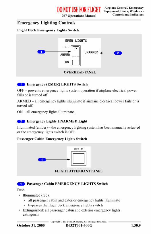
Emergency Lighting ControlsFlight Deck Emergency Lights Switch
1 Emergency (EMER) LIGHTS SwitchOFF – prevents emergency lights system operation if airplane electrical power fails or is turned off.ARMED – all emergency lights illuminate if airplane electrical power fails or is turned off.ON – all emergency lights illuminate.
2 Emergency Lights UNARMED LightIlluminated (amber) – the emergency lighting system has been manually actuated or the emergency lights switch is OFF.
Passenger Cabin Emergency Lights Switch
1 Passenger Cabin EMERGENCY LIGHTS SwitchPush –• Illuminated (red):
• all passenger cabin and exterior emergency lights illuminate• bypasses the flight deck emergency lights switch
• Extinguished: all passenger cabin and exterior emergency lights extinguish
UNARMEDOFF
EMER LIGHTS
ON
ARMED
OVERHEAD PANEL
1 2
EMER LTG
FLIGHT ATTENDANT PANEL
1
October 31, 2000
767 Operations Manual
Airplane General, Emergency Equipment, Doors, Windows -Controls and Indicators
Copyright © The Boeing Company. See title page for details.
1.30.10 D632T001-300G
Doors and Windows
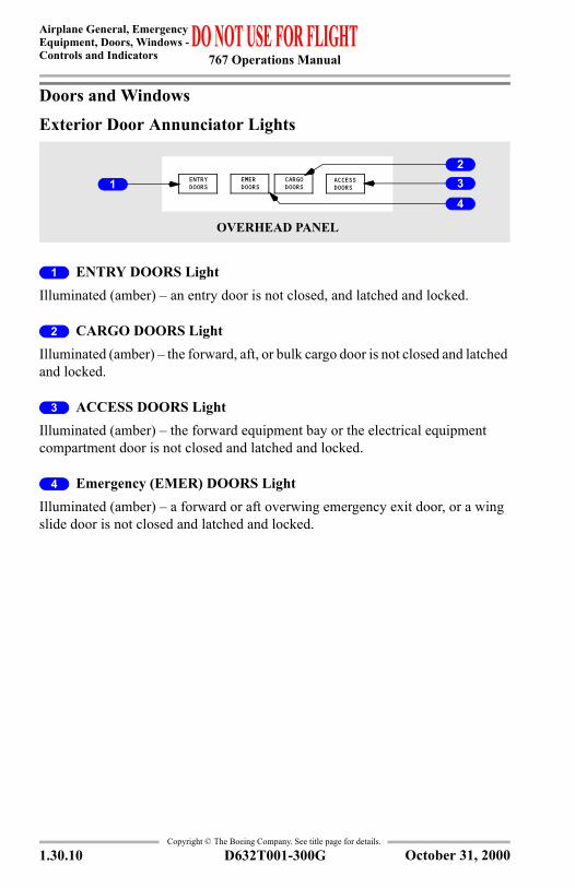
Exterior Door Annunciator Lights
1 ENTRY DOORS LightIlluminated (amber) – an entry door is not closed, and latched and locked.
2 CARGO DOORS LightIlluminated (amber) – the forward, aft, or bulk cargo door is not closed and latched and locked.
3 ACCESS DOORS LightIlluminated (amber) – the forward equipment bay or the electrical equipment compartment door is not closed and latched and locked.
4 Emergency (EMER) DOORS LightIlluminated (amber) – a forward or aft overwing emergency exit door, or a wing slide door is not closed and latched and locked.
OVERHEAD PANEL
ACCESSDOORS
CARGODOORS
EMERDOORS
ENTRYDOORS1
4
23
October 31, 2000
767 Operations Manual
Airplane General, EmergencyEquipment, Doors, Windows -
Controls and Indicators
Copyright © The Boeing Company. See title page for details.
D632T001-300G 1.30.11
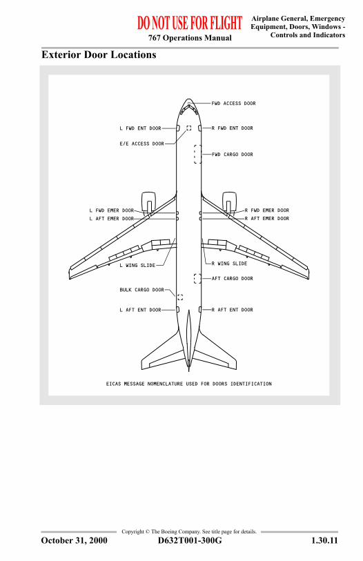
Exterior Door Locations
R FWD ENT DOORL FWD ENT DOOR
R AFT ENT DOORL AFT ENT DOOR
FWD CARGO DOOR
AFT CARGO DOOR
E/E ACCESS DOOR
FWD ACCESS DOOR
L WING SLIDE R WING SLIDE
BULK CARGO DOOR
R AFT EMER DOORL AFT EMER DOORR FWD EMER DOORL FWD EMER DOOR
EICAS MESSAGE NOMENCLATURE USED FOR DOORS IDENTIFICATION
October 31, 2000
767 Operations Manual
Airplane General, Emergency Equipment, Doors, Windows -Controls and Indicators
Copyright © The Boeing Company. See title page for details.
1.30.12 D632T001-300G
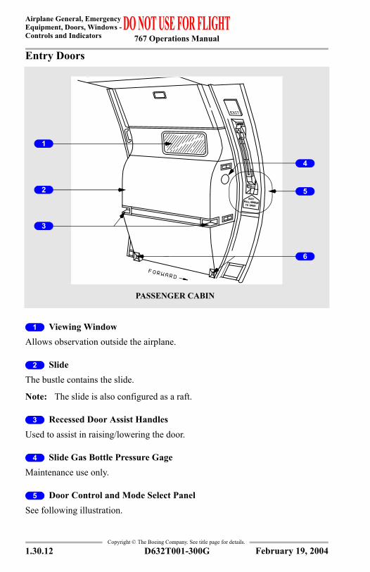
Entry Doors
1 Viewing WindowAllows observation outside the airplane.
2 Slide The bustle contains the slide.
Note: The slide is also configured as a raft.
3 Recessed Door Assist HandlesUsed to assist in raising/lowering the door.
4 Slide Gas Bottle Pressure GageMaintenance use only.
5 Door Control and Mode Select PanelSee following illustration.
PASSENGER CABIN
4
5
6
1
3
2
February 19, 2004
767 Operations Manual
Airplane General, EmergencyEquipment, Doors, Windows -
Controls and Indicators
Copyright © The Boeing Company. See title page for details.
D632T001-300G 1.30.13
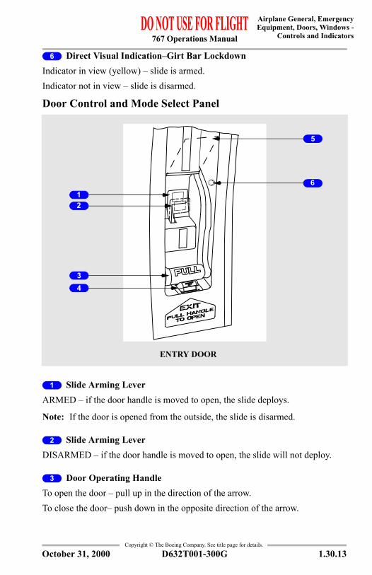
6 Direct Visual Indication–Girt Bar LockdownIndicator in view (yellow) – slide is armed.Indicator not in view – slide is disarmed.
Door Control and Mode Select Panel
1 Slide Arming LeverARMED – if the door handle is moved to open, the slide deploys.
Note: If the door is opened from the outside, the slide is disarmed.
2 Slide Arming LeverDISARMED – if the door handle is moved to open, the slide will not deploy.
3 Door Operating HandleTo open the door – pull up in the direction of the arrow.To close the door– push down in the opposite direction of the arrow.
ENTRY DOOR
1
3
2
4
6
5
October 31, 2000
767 Operations Manual
Airplane General, Emergency Equipment, Doors, Windows -Controls and Indicators
Copyright © The Boeing Company. See title page for details.
1.30.14 D632T001-300G
4 Armed IndicatorIn view – slide is armed.Not in view– slide is disarmed.
5 Slide Arming Lever CoverProtects against inadvertent movement of the slide arming lever.
6 Slide Arming Lever ReleasePush – releases slide arming lever from the slide disarmed position.
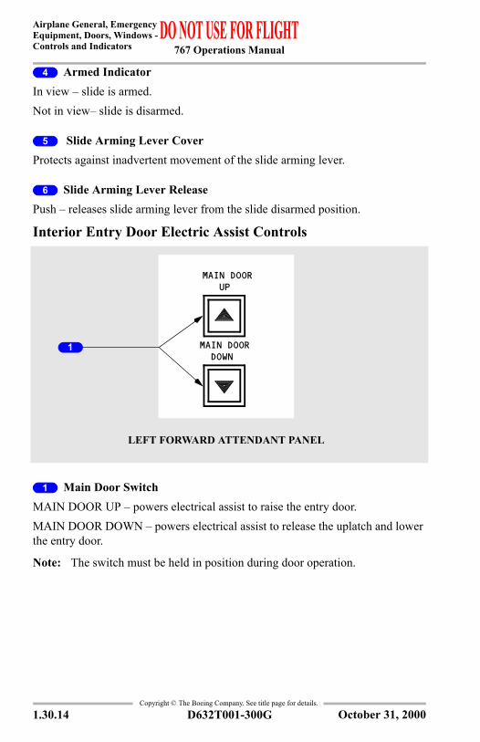
Interior Entry Door Electric Assist Controls
1 Main Door SwitchMAIN DOOR UP – powers electrical assist to raise the entry door.MAIN DOOR DOWN – powers electrical assist to release the uplatch and lower the entry door.
Note: The switch must be held in position during door operation.
LEFT FORWARD ATTENDANT PANEL
1
MAIN DOOR UP
MAIN DOOR DOWN
October 31, 2000
767 Operations Manual
Airplane General, EmergencyEquipment, Doors, Windows -
Controls and Indicators
Copyright © The Boeing Company. See title page for details.
D632T001-300G 1.30.15
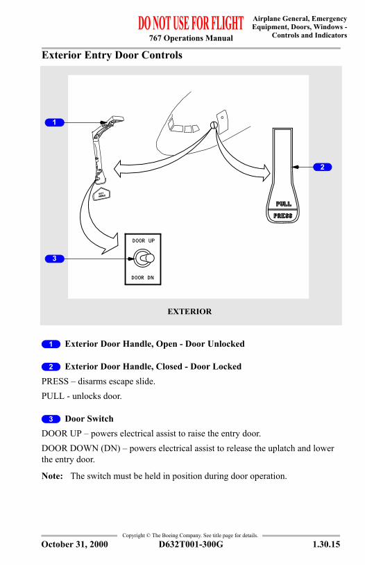
Exterior Entry Door Controls
1 Exterior Door Handle, Open - Door Unlocked
2 Exterior Door Handle, Closed - Door LockedPRESS – disarms escape slide.PULL - unlocks door.
3 Door SwitchDOOR UP – powers electrical assist to raise the entry door.DOOR DOWN (DN) – powers electrical assist to release the uplatch and lower the entry door.
Note: The switch must be held in position during door operation.
EXTERIOR
1
2
3
DOOR UP
DOOR DN
October 31, 2000
767 Operations Manual
Airplane General, Emergency Equipment, Doors, Windows -Controls and Indicators
Copyright © The Boeing Company. See title page for details.
1.30.16 D632T001-300G
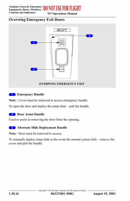
Overwing Emergency Exit Doors
1 Emergency Handle
Note: Cover must be removed to access emergency handle.
To open the door and deploy the ramp slide – pull the handle.
2 Door Assist HandleUsed to assist in removing the door from the opening.
3 Alternate Slide Deployment Handle
Note: Door must be removed to access.
To manually deploy ramp slide in the event the normal system fails – remove the cover and pull the handle.
USE ONLY
PULLREMOVE COVER
EMERGENCY
OVERWING EMERGENCY EXIT
3
2
1
August 19, 2003
767 Operations Manual
Airplane General, EmergencyEquipment, Doors, Windows -
Controls and Indicators
Copyright © The Boeing Company. See title page for details.
D632T001-300G 1.30.17
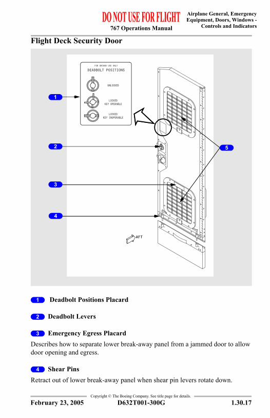
Flight Deck Security Door
1 Deadbolt Positions Placard
2 Deadbolt Levers
3 Emergency Egress PlacardDescribes how to separate lower break-away panel from a jammed door to allow door opening and egress.
4 Shear PinsRetract out of lower break-away panel when shear pin levers rotate down.
AFT
DEADBOLT POSITIONSFOR GROUND USE ONLY
KEY INOPERABLELOCKED
KEY OPERABLELOCKED
UNLOCKED
1
3
4
2 5
February 23, 2005
767 Operations Manual
Airplane General, Emergency Equipment, Doors, Windows -Controls and Indicators
Copyright © The Boeing Company. See title page for details.
1.30.18 D632T001-300G
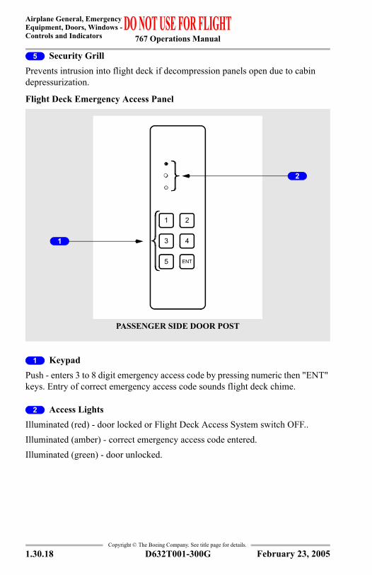
5 Security GrillPrevents intrusion into flight deck if decompression panels open due to cabin depressurization.
Flight Deck Emergency Access Panel
1 KeypadPush - enters 3 to 8 digit emergency access code by pressing numeric then "ENT" keys. Entry of correct emergency access code sounds flight deck chime.
2 Access LightsIlluminated (red) - door locked or Flight Deck Access System switch OFF..Illuminated (amber) - correct emergency access code entered.Illuminated (green) - door unlocked.
1
3
ENT5
2
4
PASSENGER SIDE DOOR POST
1
2
February 23, 2005
767 Operations Manual
Airplane General, EmergencyEquipment, Doors, Windows -
Controls and Indicators
Copyright © The Boeing Company. See title page for details.
D632T001-300G 1.30.19
Flight Deck Access System Switch
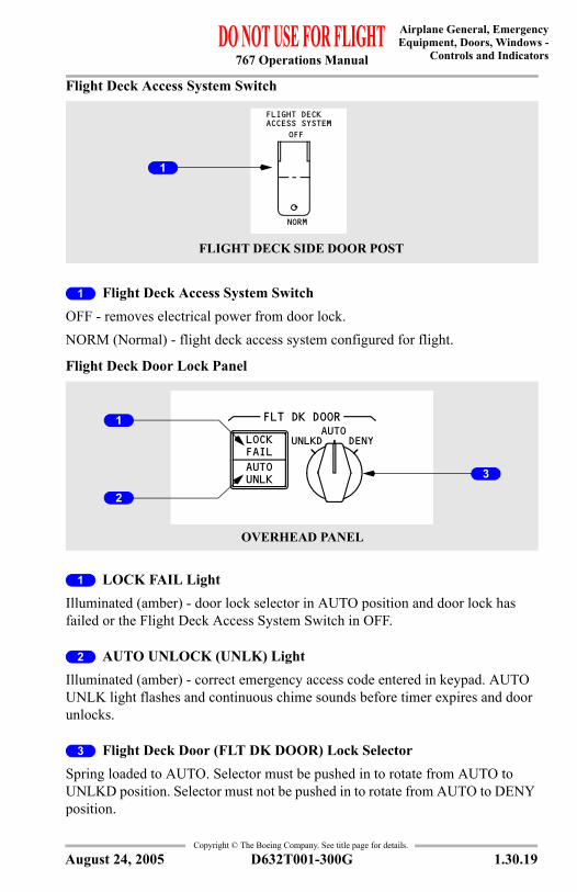
1 Flight Deck Access System SwitchOFF - removes electrical power from door lock.NORM (Normal) - flight deck access system configured for flight.
Flight Deck Door Lock Panel
1 LOCK FAIL LightIlluminated (amber) - door lock selector in AUTO position and door lock has failed or the Flight Deck Access System Switch in OFF.
2 AUTO UNLOCK (UNLK) LightIlluminated (amber) - correct emergency access code entered in keypad. AUTO UNLK light flashes and continuous chime sounds before timer expires and door unlocks.
3 Flight Deck Door (FLT DK DOOR) Lock SelectorSpring loaded to AUTO. Selector must be pushed in to rotate from AUTO to UNLKD position. Selector must not be pushed in to rotate from AUTO to DENY position.
FLIGHT DECK SIDE DOOR POST
NORM
OFF
FLIGHT DECKACCESS SYSTEM
1
UNLKD DENYAUTO
FAILLOCK
UNLKAUTO
FLT DK DOOR
3
OVERHEAD PANEL
1
2
August 24, 2005
767 Operations Manual
Airplane General, Emergency Equipment, Doors, Windows -Controls and Indicators
Copyright © The Boeing Company. See title page for details.
1.30.20 D632T001-300G
UNLKD - door unlocked while selector in UNLKD.AUTO - door locked. Allows door to unlock after entry of emergency access code and expiration of timer, unless crew takes action.DENY - rejects keypad entry request and prevents further emergency access code entry for a time period.
Flight Deck Number Two Window
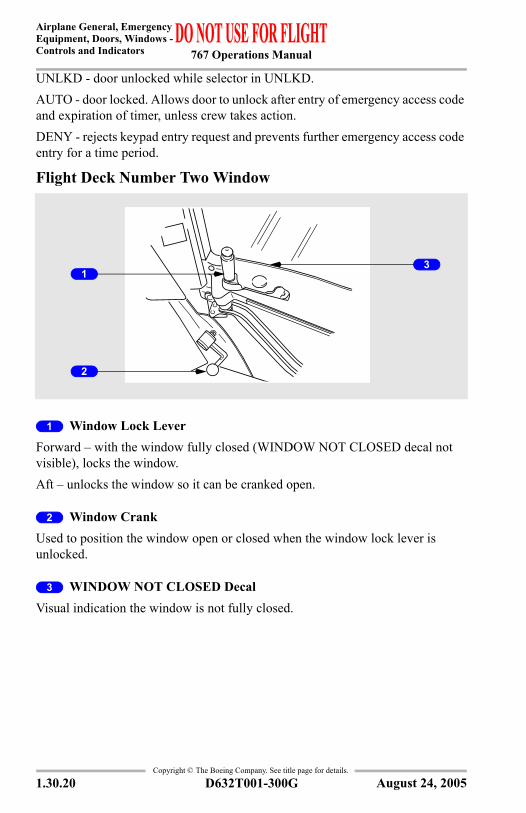
1 Window Lock LeverForward – with the window fully closed (WINDOW NOT CLOSED decal not visible), locks the window.Aft – unlocks the window so it can be cranked open.
2 Window CrankUsed to position the window open or closed when the window lock lever is unlocked.
3 WINDOW NOT CLOSED DecalVisual indication the window is not fully closed.
1
2
3
August 24, 2005
767 Operations Manual
Airplane General, EmergencyEquipment, Doors, Windows -
Controls and Indicators
Copyright © The Boeing Company. See title page for details.
D632T001-300G 1.30.21
Oxygen Systems
Oxygen Indications
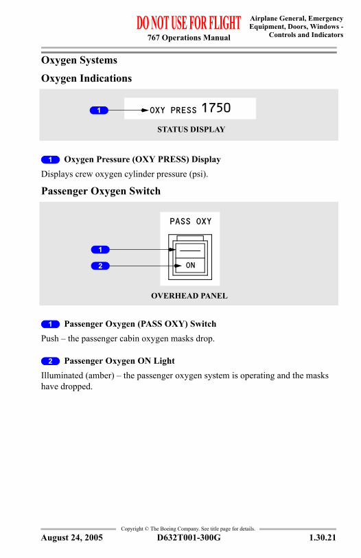
1 Oxygen Pressure (OXY PRESS) DisplayDisplays crew oxygen cylinder pressure (psi).
Passenger Oxygen Switch
1 Passenger Oxygen (PASS OXY) SwitchPush – the passenger cabin oxygen masks drop.
2 Passenger Oxygen ON LightIlluminated (amber) – the passenger oxygen system is operating and the masks have dropped.
STATUS DISPLAY
OXY PRESS 17501
PASS OXY
ON
OVERHEAD PANEL
1
2
August 24, 2005
767 Operations Manual
Airplane General, Emergency Equipment, Doors, Windows -Controls and Indicators
Copyright © The Boeing Company. See title page for details.
1.30.22 D632T001-300G
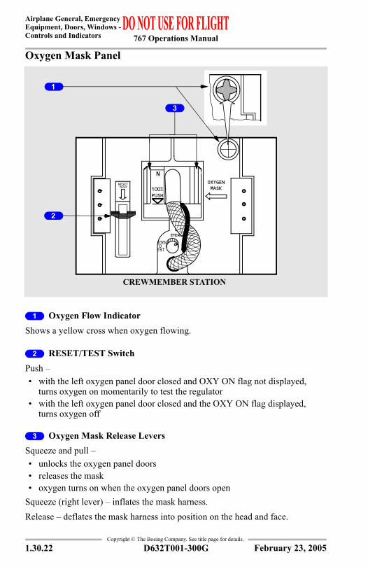
Oxygen Mask Panel
1 Oxygen Flow IndicatorShows a yellow cross when oxygen flowing.
2 RESET/TEST SwitchPush –• with the left oxygen panel door closed and OXY ON flag not displayed,
turns oxygen on momentarily to test the regulator• with the left oxygen panel door closed and the OXY ON flag displayed,
turns oxygen off
3 Oxygen Mask Release LeversSqueeze and pull –• unlocks the oxygen panel doors• releases the mask• oxygen turns on when the oxygen panel doors open
Squeeze (right lever) – inflates the mask harness.Release – deflates the mask harness into position on the head and face.
TESTRESET OXYGEN
MASK100%PUSH
N
CREWMEMBER STATION
1
2
3
February 23, 2005
767 Operations Manual
Airplane General, EmergencyEquipment, Doors, Windows -
Controls and Indicators
Copyright © The Boeing Company. See title page for details.
D632T001-300G 1.30.23
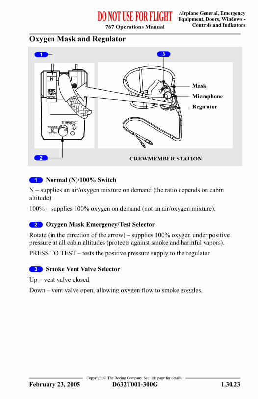
Oxygen Mask and Regulator
1 Normal (N)/100% SwitchN – supplies an air/oxygen mixture on demand (the ratio depends on cabin altitude).100% – supplies 100% oxygen on demand (not an air/oxygen mixture).
2 Oxygen Mask Emergency/Test Selector Rotate (in the direction of the arrow) – supplies 100% oxygen under positive pressure at all cabin altitudes (protects against smoke and harmful vapors).PRESS TO TEST – tests the positive pressure supply to the regulator.
3 Smoke Vent Valve Selector Up – vent valve closedDown – vent valve open, allowing oxygen flow to smoke goggles.
Mask
Microphone
Regulator
CREWMEMBER STATION
31
2
February 23, 2005
767 Operations Manual
Airplane General, Emergency Equipment, Doors, Windows -Controls and Indicators
Copyright © The Boeing Company. See title page for details.
1.30.24 D632T001-300G
IntentionallyBlank
August 19, 2003
767 Operations Manual
Chapter 1Airplane General, Emergency Equipment, Doors, WindowsSystems Description Section 40
Copyright © The Boeing Company. See title page for details.
D632T001-300G 1.40.1
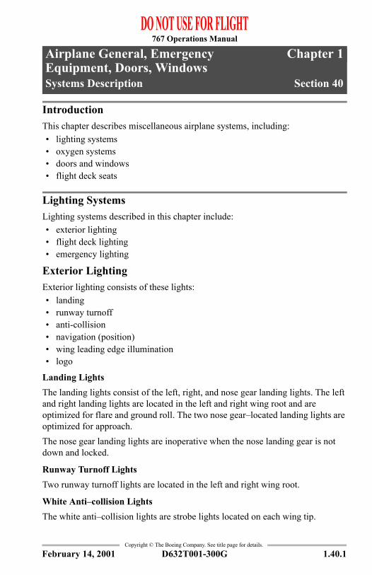
1.40 Airplane General, Emergency Equipment, Doors, Windows-Systems DescriptionIntroductionThis chapter describes miscellaneous airplane systems, including:• lighting systems• oxygen systems• doors and windows• flight deck seats
Lighting SystemsLighting systems described in this chapter include:• exterior lighting• flight deck lighting• emergency lighting
Exterior LightingExterior lighting consists of these lights:• landing• runway turnoff• anti-collision• navigation (position)• wing leading edge illumination• logo
Landing LightsThe landing lights consist of the left, right, and nose gear landing lights. The left and right landing lights are located in the left and right wing root and are optimized for flare and ground roll. The two nose gear–located landing lights are optimized for approach.The nose gear landing lights are inoperative when the nose landing gear is not down and locked.
Runway Turnoff LightsTwo runway turnoff lights are located in the left and right wing root.
White Anti–collision LightsThe white anti–collision lights are strobe lights located on each wing tip.
February 14, 2001
767 Operations Manual
Airplane General, Emergency Equipment, Doors, Windows -Systems Description
Copyright © The Boeing Company. See title page for details.
1.40.2 D632T001-300G
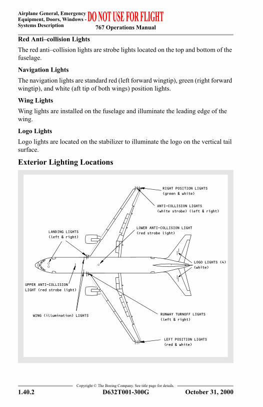
Red Anti–collision LightsThe red anti–collision lights are strobe lights located on the top and bottom of the fuselage.
Navigation LightsThe navigation lights are standard red (left forward wingtip), green (right forward wingtip), and white (aft tip of both wings) position lights.
Wing LightsWing lights are installed on the fuselage and illuminate the leading edge of the wing.
Logo LightsLogo lights are located on the stabilizer to illuminate the logo on the vertical tail surface.
Exterior Lighting Locations
Ñ
Ñ
Ñ
Ñ
Ñ
ÑÑÑ
ÑÑÑ
Ñ
Ñ
Ñ
Ñ
RUNWAY TURNOFF LIGHTS(left & right)
RIGHT POSITION LIGHTS(green & white)
LOWER ANTI-COLLISION LIGHT(red strobe light)
WING (illumination) LIGHTS
LEFT POSITION LIGHTS(red & white)
(left & right)LANDING LIGHTS
(white)
ANTI-COLLISION LIGHTS(white strobe) (left & right)
Ñ
Ñ
LOGO LIGHTS (4)
UPPER ANTI-COLLISIONLIGHT (red strobe light)
October 31, 2000
767 Operations Manual
Airplane General, EmergencyEquipment, Doors, Windows -
Systems Description
Copyright © The Boeing Company. See title page for details.
D632T001-300G 1.40.3
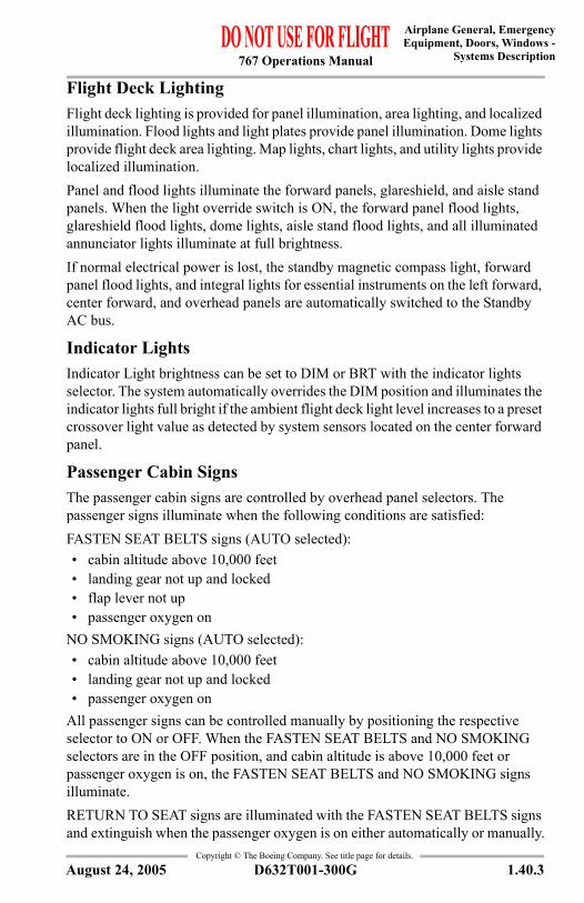
Flight Deck LightingFlight deck lighting is provided for panel illumination, area lighting, and localized illumination. Flood lights and light plates provide panel illumination. Dome lights provide flight deck area lighting. Map lights, chart lights, and utility lights provide localized illumination.Panel and flood lights illuminate the forward panels, glareshield, and aisle stand panels. When the light override switch is ON, the forward panel flood lights, glareshield flood lights, dome lights, aisle stand flood lights, and all illuminated annunciator lights illuminate at full brightness. If normal electrical power is lost, the standby magnetic compass light, forward panel flood lights, and integral lights for essential instruments on the left forward, center forward, and overhead panels are automatically switched to the Standby AC bus.
Indicator LightsIndicator Light brightness can be set to DIM or BRT with the indicator lights selector. The system automatically overrides the DIM position and illuminates the indicator lights full bright if the ambient flight deck light level increases to a preset crossover light value as detected by system sensors located on the center forward panel.
Passenger Cabin SignsThe passenger cabin signs are controlled by overhead panel selectors. The passenger signs illuminate when the following conditions are satisfied:FASTEN SEAT BELTS signs (AUTO selected):• cabin altitude above 10,000 feet• landing gear not up and locked• flap lever not up• passenger oxygen on
NO SMOKING signs (AUTO selected):• cabin altitude above 10,000 feet• landing gear not up and locked• passenger oxygen on
All passenger signs can be controlled manually by positioning the respective selector to ON or OFF. When the FASTEN SEAT BELTS and NO SMOKING selectors are in the OFF position, and cabin altitude is above 10,000 feet or passenger oxygen is on, the FASTEN SEAT BELTS and NO SMOKING signs illuminate.RETURN TO SEAT signs are illuminated with the FASTEN SEAT BELTS signs and extinguish when the passenger oxygen is on either automatically or manually.
August 24, 2005
767 Operations Manual
Airplane General, Emergency Equipment, Doors, Windows -Systems Description
Copyright © The Boeing Company. See title page for details.
1.40.4 D632T001-300G
When the passenger signs illuminate or extinguish, a low tone sounds over the PA system.
Emergency LightingThe aft flight deck dome light (one bulb only), passenger cabin interior and exterior lights are powered by the emergency lighting system. These lights provide illumination for evacuating the airplane. The system is controlled by the emergency lights switch on the overhead panel. The switch can be used to manually activate or arm the system for automatic operation. Automatic operation occurs if DC power fails or is turned off when the system is armed. The emergency lighting system can also be controlled by the emergency lights switch on the flight attendant switch panel.When the emergency lights switch on the flight deck is armed, and the slide arming lever is in the SLIDE ARMED position, moving the door handle to the open position will cause the exterior emergency lights on that side of the airplane to illuminate.In addition, when the emergency lights switch on the flight deck is armed, moving an overwing emergency exit door handle to the open position will cause the exterior emergency lights on that side of the airplane to illuminate.The emergency lighting system is powered by remote batteries. Battery charge is maintained by the airplane electrical system. A fully charged battery provides at least 15 minutes of operation.The UNARMED light illuminates and the EICAS advisory message EMER LIGHTS displays if the emergency lights switch is not in the ARMED position.
Interior Emergency LightingInterior emergency lighting consists of door, aisle, escape path, and lighted exit signs.Battery powered exit lights are located at each cabin exit.
Exterior Emergency LightingExterior emergency lights are located at each entry door and overwing emergency exit door. Lights are also installed in each slide to illuminate the ground at the end of the slide.
Oxygen SystemsTwo independent oxygen systems are provided, one for the flight crew and one for the passengers. Portable oxygen cylinders are located throughout the airplane for emergency use.
February 23, 2005
767 Operations Manual
Airplane General, EmergencyEquipment, Doors, Windows -
Systems Description
Copyright © The Boeing Company. See title page for details.
D632T001-300G 1.40.5
Flight Crew Oxygen SystemThe flight crew oxygen system uses quick–donning masks and regulators located at each crew station. Oxygen pressure is displayed on the lower EICAS status display.Flight crew and observer masks and regulators are installed in oxygen mask panels near each seat. Squeezing the red oxygen mask release levers releases the mask from stowage. Removing the mask:• inflates the mask harness• momentarily displays the yellow oxygen flow indicator
Passenger Oxygen SystemThe passenger oxygen system is supplied by individual chemical oxygen generators. The oxygen system provides oxygen to the passenger, attendant stations, and lavatory service units. The passenger oxygen masks and chemical oxygen generators are located above the passenger seats in passenger service units (PSUs). Oxygen flows from a PSU generator when any mask hanging from that PSU is pulled. The masks automatically drop from the PSUs if cabin altitude exceeds 14,000 feet. The passenger masks can be manually deployed from the flight deck by pushing the passenger oxygen switch. The passenger oxygen ON light illuminates and EICAS advisory message PASS OXYGEN ON displays when the system is activated.
Portable Oxygen BottlesPortable oxygen bottles are stowed in various locations in the passenger cabin. The bottles are fitted with disposable masks and are used for first aid purposes or as walk–around units.
Doors and WindowsThe airplane has four passenger entry doors, four overwing emergency exit doors, one flight deck door (the flight deck/passenger cabin entry), and three cargo doors. It also has electrical equipment and forward equipment bay access doors.The flight deck number two windows, one on the left and one on the right, can be opened by the flight crew. An EICAS message is displayed when a passenger entry door, overwing emergency exit door, cargo door or access door is not closed and latched, and locked.
August 24, 2005
767 Operations Manual
Airplane General, Emergency Equipment, Doors, Windows -Systems Description
Copyright © The Boeing Company. See title page for details.
1.40.6 D632T001-300G
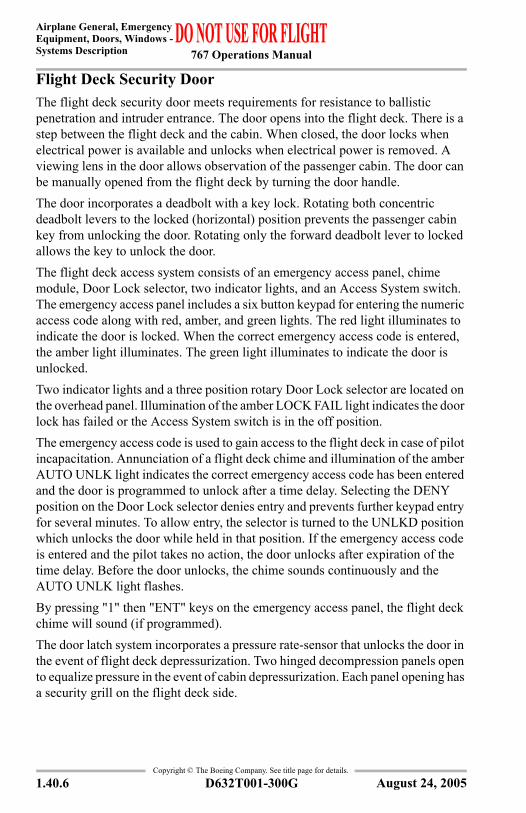
Flight Deck Security Door The flight deck security door meets requirements for resistance to ballistic penetration and intruder entrance. The door opens into the flight deck. There is a step between the flight deck and the cabin. When closed, the door locks when electrical power is available and unlocks when electrical power is removed. A viewing lens in the door allows observation of the passenger cabin. The door can be manually opened from the flight deck by turning the door handle. The door incorporates a deadbolt with a key lock. Rotating both concentric deadbolt levers to the locked (horizontal) position prevents the passenger cabin key from unlocking the door. Rotating only the forward deadbolt lever to locked allows the key to unlock the door. The flight deck access system consists of an emergency access panel, chime module, Door Lock selector, two indicator lights, and an Access System switch. The emergency access panel includes a six button keypad for entering the numeric access code along with red, amber, and green lights. The red light illuminates to indicate the door is locked. When the correct emergency access code is entered, the amber light illuminates. The green light illuminates to indicate the door is unlocked. Two indicator lights and a three position rotary Door Lock selector are located on the overhead panel. Illumination of the amber LOCK FAIL light indicates the door lock has failed or the Access System switch is in the off position.The emergency access code is used to gain access to the flight deck in case of pilot incapacitation. Annunciation of a flight deck chime and illumination of the amber AUTO UNLK light indicates the correct emergency access code has been entered and the door is programmed to unlock after a time delay. Selecting the DENY position on the Door Lock selector denies entry and prevents further keypad entry for several minutes. To allow entry, the selector is turned to the UNLKD position which unlocks the door while held in that position. If the emergency access code is entered and the pilot takes no action, the door unlocks after expiration of the time delay. Before the door unlocks, the chime sounds continuously and the AUTO UNLK light flashes. By pressing "1" then "ENT" keys on the emergency access panel, the flight deck chime will sound (if programmed). The door latch system incorporates a pressure rate-sensor that unlocks the door in the event of flight deck depressurization. Two hinged decompression panels open to equalize pressure in the event of cabin depressurization. Each panel opening has a security grill on the flight deck side.
August 24, 2005
767 Operations Manual
Airplane General, EmergencyEquipment, Doors, Windows -
Systems Description
Copyright © The Boeing Company. See title page for details.
D632T001-300G 1.40.7
Features are included to prevent a jammed door due to structural deformation. A lower break-away panel is attached to the main door section by interlocking extrusions and two shear pins. If sufficient upward force occurs, the pins will shear and the break-away panel will separate from the door. If the pins fail to shear, they can be retracted manually to aid in egress. An angled door jamb aids in forcing the door open into the flight deck in case of surrounding bulkhead deformation.
Flight Deck Number Two WindowsThe flight deck number two windows can be opened on the ground or in flight. The flight deck number two windows can be used for emergency evacuation. The window lock lever locks or unlocks the window. Rotating the window crank opens and closes the window.A WINDOW NOT CLOSED placard is visible when the window is open.The windows can be opened or closed in flight with minor flight deck consequences if the airplane is unpressurized. Because the force required to move the crank increases with airspeed, it is recommended not to exceed VREF 30 + 80 with a window open. It may not be possible to open or close the window at speeds above 250 knots. With the window open, voice, interphone, and radio audio cannot be heard due to high noise levels. Prior communications arrangements with the controlling agency should be established before opening the window. The design provides an area of relatively calm air over the open window. Forward visibility can be maintained by looking out of the open window.
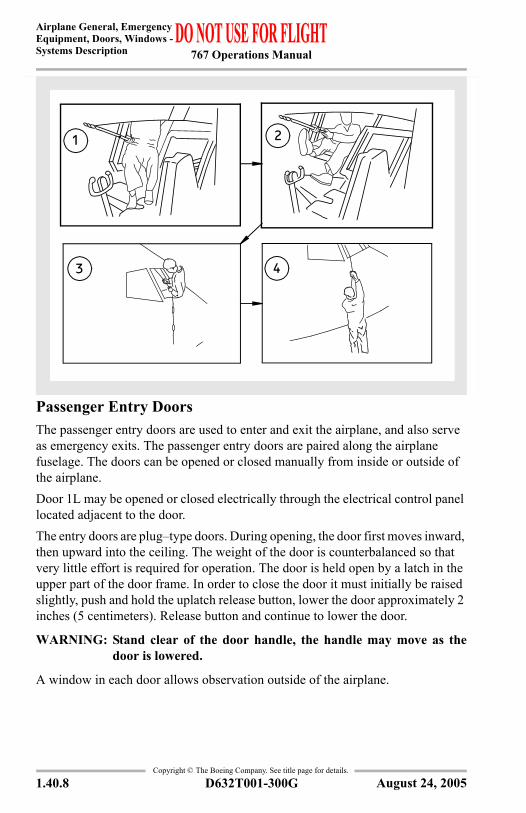
Flight Deck Window Emergency EgressIf the flight deck number two windows must be used for emergency evacuation, exit in accordance with the following illustration.
CAUTION: Ensure the rope is securely fastened to the airplane.
August 24, 2005
767 Operations Manual
Airplane General, Emergency Equipment, Doors, Windows -Systems Description
Copyright © The Boeing Company. See title page for details.
1.40.8 D632T001-300G
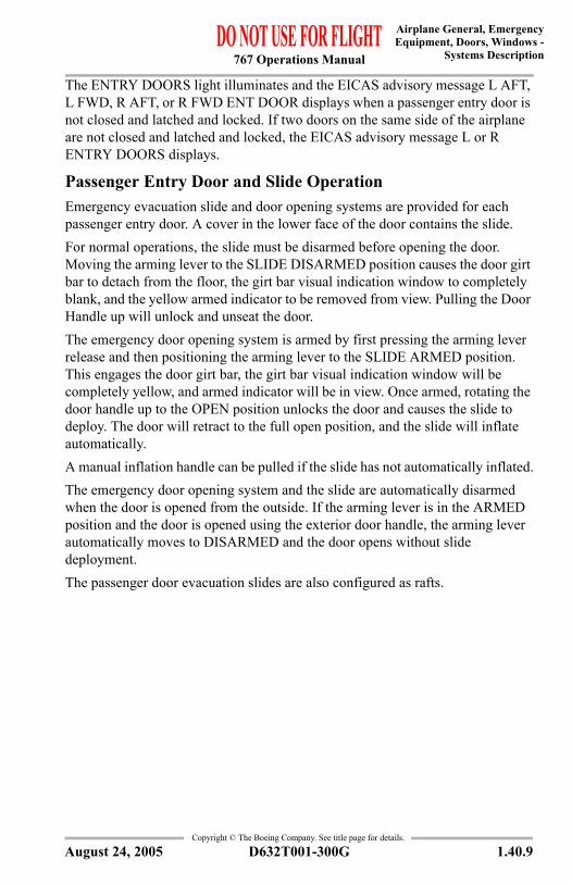
Passenger Entry DoorsThe passenger entry doors are used to enter and exit the airplane, and also serve as emergency exits. The passenger entry doors are paired along the airplane fuselage. The doors can be opened or closed manually from inside or outside of the airplane.Door 1L may be opened or closed electrically through the electrical control panel located adjacent to the door.The entry doors are plug–type doors. During opening, the door first moves inward, then upward into the ceiling. The weight of the door is counterbalanced so that very little effort is required for operation. The door is held open by a latch in the upper part of the door frame. In order to close the door it must initially be raised slightly, push and hold the uplatch release button, lower the door approximately 2 inches (5 centimeters). Release button and continue to lower the door.
WARNING: Stand clear of the door handle, the handle may move as thedoor is lowered.
A window in each door allows observation outside of the airplane.
3 4
1 2
August 24, 2005
767 Operations Manual
Airplane General, EmergencyEquipment, Doors, Windows -
Systems Description
Copyright © The Boeing Company. See title page for details.
D632T001-300G 1.40.9
The ENTRY DOORS light illuminates and the EICAS advisory message L AFT, L FWD, R AFT, or R FWD ENT DOOR displays when a passenger entry door is not closed and latched and locked. If two doors on the same side of the airplane are not closed and latched and locked, the EICAS advisory message L or R ENTRY DOORS displays.
Passenger Entry Door and Slide OperationEmergency evacuation slide and door opening systems are provided for each passenger entry door. A cover in the lower face of the door contains the slide.For normal operations, the slide must be disarmed before opening the door. Moving the arming lever to the SLIDE DISARMED position causes the door girt bar to detach from the floor, the girt bar visual indication window to completely blank, and the yellow armed indicator to be removed from view. Pulling the Door Handle up will unlock and unseat the door. The emergency door opening system is armed by first pressing the arming lever release and then positioning the arming lever to the SLIDE ARMED position. This engages the door girt bar, the girt bar visual indication window will be completely yellow, and armed indicator will be in view. Once armed, rotating the door handle up to the OPEN position unlocks the door and causes the slide to deploy. The door will retract to the full open position, and the slide will inflate automatically.A manual inflation handle can be pulled if the slide has not automatically inflated.The emergency door opening system and the slide are automatically disarmed when the door is opened from the outside. If the arming lever is in the ARMED position and the door is opened using the exterior door handle, the arming lever automatically moves to DISARMED and the door opens without slide deployment.The passenger door evacuation slides are also configured as rafts.
August 24, 2005
767 Operations Manual
Airplane General, Emergency Equipment, Doors, Windows -Systems Description
Copyright © The Boeing Company. See title page for details.
1.40.10 D632T001-300G
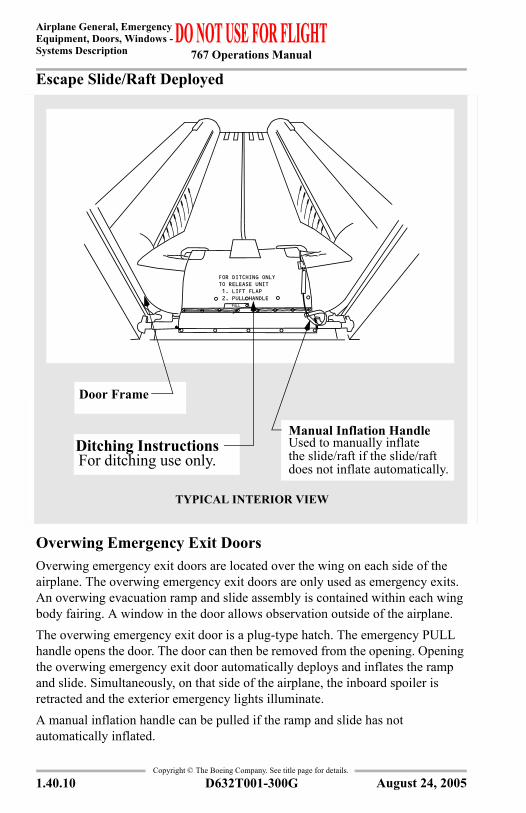
Escape Slide/Raft Deployed
Overwing Emergency Exit DoorsOverwing emergency exit doors are located over the wing on each side of the airplane. The overwing emergency exit doors are only used as emergency exits. An overwing evacuation ramp and slide assembly is contained within each wing body fairing. A window in the door allows observation outside of the airplane.The overwing emergency exit door is a plug-type hatch. The emergency PULL handle opens the door. The door can then be removed from the opening. Opening the overwing emergency exit door automatically deploys and inflates the ramp and slide. Simultaneously, on that side of the airplane, the inboard spoiler is retracted and the exterior emergency lights illuminate.A manual inflation handle can be pulled if the ramp and slide has not automatically inflated.
Door Frame
Ditching InstructionsFor ditching use only.
Manual Inflation HandleUsed to manually inflatethe slide/raft if the slide/raftdoes not inflate automatically.
TYPICAL INTERIOR VIEW
FOR DITCHING ONLYTO RELEASE UNIT 1. LIFT FLAP 2. PULL HANDLE
PULL
August 24, 2005
767 Operations Manual
Airplane General, EmergencyEquipment, Doors, Windows -
Systems Description
Copyright © The Boeing Company. See title page for details.
D632T001-300G 1.40.11
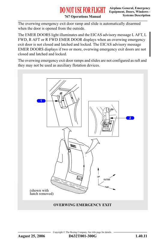
The overwing emergency exit door ramp and slide is automatically disarmed when the door is opened from the outside.The EMER DOORS light illuminates and the EICAS advisory message L AFT, L FWD, R AFT or R FWD EMER DOOR displays when an overwing emergency exit door is not closed and latched and locked. The EICAS advisory message EMER DOORS displays if two or more, overwing emergency exit doors are not closed and latched and locked.The overwing emergency exit door ramps and slides are not configured as raft and they may not be used as auxiliary flotation devices.
1
2
OVERWING EMERGENCY EXIT
(shown withhatch removed)
UPOUTBD
FWD
August 25, 2006
767 Operations Manual
Airplane General, Emergency Equipment, Doors, Windows -Systems Description
Copyright © The Boeing Company. See title page for details.
1.40.12 D632T001-300G
1 Manual Inflation HandlePull – Deploys ramp slide in the event normal system fails.• one per exit
2 Escape Strap (FWD Door only)Remove Cover – Pull out and attach hook to wing fitting.• installed on forward door only
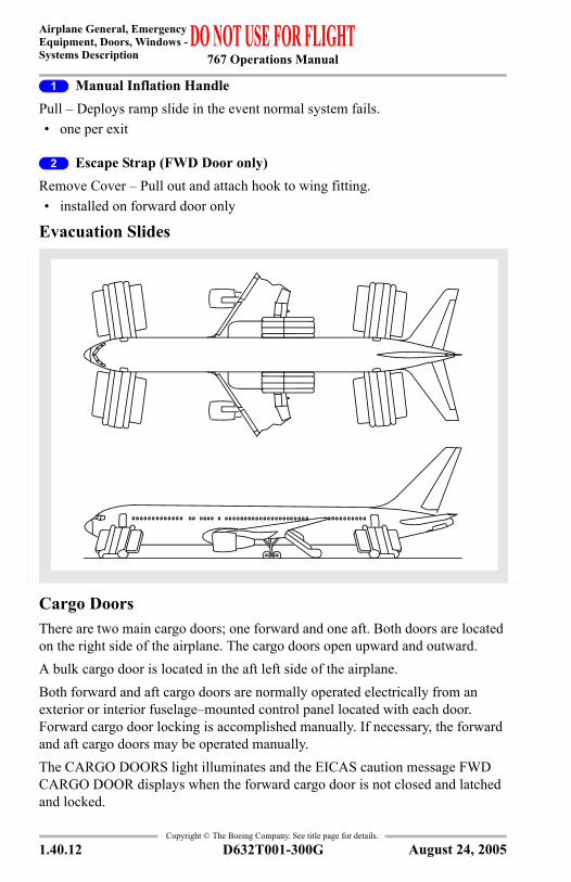
Evacuation Slides
Cargo DoorsThere are two main cargo doors; one forward and one aft. Both doors are located on the right side of the airplane. The cargo doors open upward and outward. A bulk cargo door is located in the aft left side of the airplane. Both forward and aft cargo doors are normally operated electrically from an exterior or interior fuselage–mounted control panel located with each door. Forward cargo door locking is accomplished manually. If necessary, the forward and aft cargo doors may be operated manually.The CARGO DOORS light illuminates and the EICAS caution message FWD CARGO DOOR displays when the forward cargo door is not closed and latched and locked.
August 24, 2005
767 Operations Manual
Airplane General, EmergencyEquipment, Doors, Windows -
Systems Description
Copyright © The Boeing Company. See title page for details.
D632T001-300G 1.40.13
The CARGO DOORS light illuminates and the EICAS advisory message AFT or BULK CARGO DOOR displays when either cargo door is not closed and latched and locked. The EICAS advisory message CARGO DOORS displays if both cargo doors are not closed and latched and locked.
Flight Deck SeatsThe pilot seats:• recline• adjust vertically• adjust forward and aft• adjust for thigh support• adjust for the lumbar region of the back
The seats also have:• adjustable armrests• crotch straps• inertial–reel shoulder harnesses with manual locks• lap belts• adjustable headrests
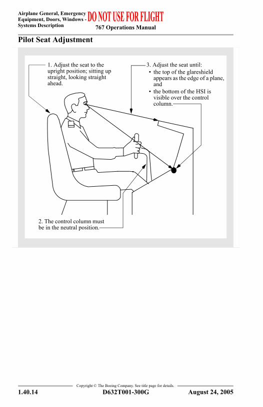
The seats move outboard during the last four inches of travel. Manual controls provide forward, aft, and vertical adjustment.Lumbar and thigh pad support can be adjusted using the adjustment hand wheels. Armrest pitch can be adjusted using the control knob under the armrest. The armrests can be stowed vertically for easier seat access.Adjust the seat to obtain the optimum eye position as shown on the following illustration.
August 24, 2005
767 Operations Manual
Airplane General, Emergency Equipment, Doors, Windows -Systems Description
Copyright © The Boeing Company. See title page for details.
1.40.14 D632T001-300G
Pilot Seat Adjustment
2. The control column must be in the neutral position.
1. Adjust the seat to the upright position; sitting up straight, looking straight ahead.
3. Adjust the seat until:• the top of the glareshield
appears as the edge of a plane, and
• the bottom of the HSI is visible over the control column.
August 24, 2005
767 Operations Manual
Chapter 1Airplane General, Emergency Equipment, Doors, WindowsEmergency Equipment Section 45
Copyright © The Boeing Company. See title page for details.
D632T001-300G 1.45.1
1.45 Airplane General, Emergency Equipment, Doors, Windows-Emergency EquipmentIntroductionThis chapter describes miscellaneous airplane systems, including:• emergency equipment• emergency equipment locations
Emergency EquipmentEmergency equipment described in this section includes:• fire extinguishers• miscellaneous emergency equipment
Fire ExtinguishersHalon (BCF) and Water (H2O) fire extinguishers are located throughout the passenger cabin and flight deck. See emergency equipment diagram for location.
WARNING: If a fire extinguisher is to be discharged in the flight deck area,all flight crew members must wear oxygen masks and use100% oxygen with emergency selected.
CAUTION: For electrical fires, remove the power source as soon aspossible. Avoid discharging directly on persons due topossibility of suffocating effects. Do not discharge too close tofire as the discharge stream may scatter the fire. As with anyfire, keep away from the fuel source. Avoid breathing vapors,fumes, and heated smoke as much as possible.
Halon Fire ExtinguishersHalon fire extinguishers contain a liquefied gas agent under pressure. The extinguisher pressure indicator shows three pressure ranges:• acceptable• recharge• overcharged
A safety pin with a pull ring prevents accidental trigger movement. When released, the liquefied gas agent vaporizes and extinguishes the fire. The extinguisher is effective on all types of fires, but is used primarily on electrical, fuel, and grease fires.
August 24, 2005
767 Operations Manual
Airplane General, Emergency Equipment, Doors, Windows -Emergency Equipment
Copyright © The Boeing Company. See title page for details.
1.45.2 D632T001-300G
To use the Halon fire extinguisher, hold the extinguisher upright, and remove the ringed safety pin. From a distance of 8 to 10 feet, aim the extinguisher nozzle at the base of the flames and press the top lever.
Water (H2O) Fire ExtinguishersWater fire extinguishers contain a solution of water mixed with anti-freeze. The container is pressurized by a CO2 cartridge. The extinguisher should be used on fabric, paper or wood fires only.
CAUTION: Do not use on electrical or grease type fires.
To use the Water fire extinguisher, hold the extinguisher upright and rotate the handle fully clockwise. Aim the extinguisher at the base of the flame and pull the trigger.
Miscellaneous Emergency EquipmentAdditional equipment is stowed at strategic locations throughout the airplane. This may include a crash axe, megaphones, flashlights and first aid kits. Life vests are stowed at each crew member station and at each passenger seat.
Emergency Locator Transmitters (ELTs)ELTs are installed in slide/raft bustles. The ELTs automatically transmit when submerged in water.Portable ELT’s may be installed in the passenger cabin, as shown in the Emergency Equipment Locations diagram.
Escape RopesEscape ropes are attached to the airplane structure above both number two flight deck windows. The ropes are stowed in compartments above the pilot seats. Prior to dropping the rope out of the window, ensure the rope is attached by pulling down.
August 24, 2005
767 Operations Manual
Airplane General, EmergencyEquipment, Doors, Windows -
Emergency Equipment
Copyright © The Boeing Company. See title page for details.
D632T001-300G 1.45.3
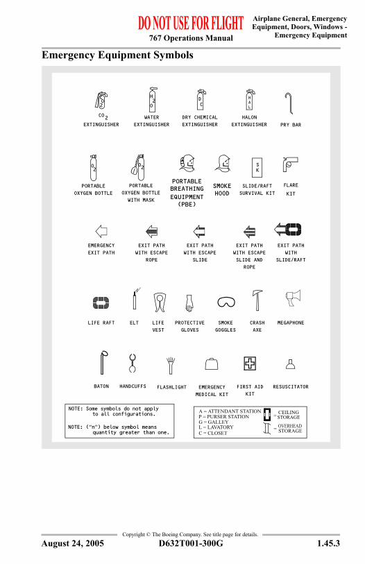
Emergency Equipment Symbols
KIT
FLARE
FIRST AIDKIT
RESUSCITATORMEDICAL KITEMERGENCYFLASHLIGHTHANDCUFFSBATON
MEGAPHONECRASHAXE
SMOKEGOGGLES
PROTECTIVEGLOVES
LIFEVEST
ELTLIFE RAFT
ROPE
EXIT PATHWITH
SLIDE/RAFT
EXIT PATHWITH ESCAPESLIDE AND
WITH ESCAPE EXIT PATH
SLIDEROPE
EXIT PATHWITH ESCAPE
PRY BAREXTINGUISHER
HAL
HALONDRY CHEMICALEXTINGUISHER
DC
WATEREXTINGUISHER
H2O
WITH MASKOXYGEN BOTTLE
PORTABLE
S
SLIDE/RAFTSURVIVAL KIT
K
PORTABLEOXYGEN BOTTLE
O2
2OC
CO2EXTINGUISHER
EMERGENCY EXIT PATH
O2
SMOKEHOODEQUIPMENT
PORTABLEBREATHING
(PBE)
O2
A = ATTENDANT STATION
G = GALLEYL = LAVATORY
P = PURSER STATION
C = CLOSETOVERHEADSTORAGE
CO2
NOTE: Some symbols do not apply to all configurations.
NOTE: ("n") below symbol means quantity greater than one.
CEILINGSTORAGE
=
=
August 24, 2005
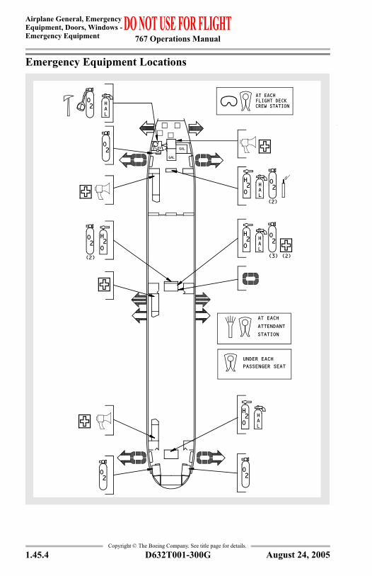
767 Operations Manual
Airplane General, Emergency Equipment, Doors, Windows -Emergency Equipment
Copyright © The Boeing Company. See title page for details.
1.45.4 D632T001-300G
Emergency Equipment Locations
AT EACH
CREW STATIONFLIGHT DECK
PASSENGER SEATUNDER EACH
ATTENDANTSTATION
AT EACH
LAV GAL
GAL
O2
O2
O2
H2O
HAL
HAL
O2
H2O
O2
H2O
HAL
H2O
O2H
AL
(2)(3)
(2)
O2
(2)
August 24, 2005
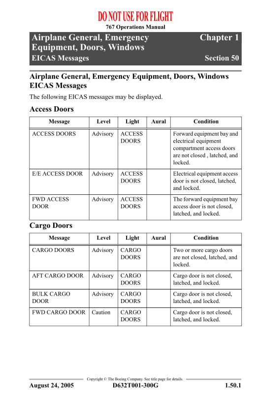
767 Operations Manual
Chapter 1Airplane General, Emergency Equipment, Doors, WindowsEICAS Messages Section 50
Copyright © The Boeing Company. See title page for details.
D632T001-300G 1.50.1
1.50 Airplane General, Emergency Equipment, Doors, Windows-EICAS MessagesAirplane General, Emergency Equipment, Doors, Windows EICAS MessagesThe following EICAS messages may be displayed.
Access Doors
Cargo Doors
Message Level Light Aural Condition
ACCESS DOORS Advisory ACCESS DOORS
Forward equipment bay and electrical equipment compartment access doors are not closed , latched, and locked.
E/E ACCESS DOOR Advisory ACCESS DOORS
Electrical equipment access door is not closed, latched, and locked.
FWD ACCESS DOOR
Advisory ACCESS DOORS
The forward equipment bay access door is not closed, latched, and locked.
Message Level Light Aural Condition
CARGO DOORS Advisory CARGO DOORS
Two or more cargo doors are not closed, latched, and locked.
AFT CARGO DOOR Advisory CARGO DOORS
Cargo door is not closed, latched, and locked.
BULK CARGO DOOR
Advisory CARGO DOORS
Cargo door is not closed, latched, and locked.
FWD CARGO DOOR Caution CARGO DOORS
Cargo door is not closed, latched, and locked.
August 24, 2005
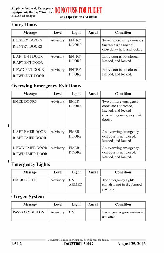
767 Operations Manual
Airplane General, Emergency Equipment, Doors, Windows -EICAS Messages
Copyright © The Boeing Company. See title page for details.
1.50.2 D632T001-300G
Entry Doors
Overwing Emergency Exit Doors
Emergency Lights
Oxygen System
Message Level Light Aural Condition
L ENTRY DOORS
R ENTRY DOORS
Advisory ENTRY DOORS
Two or more entry doors on the same side are not closed, latched, and locked.
L AFT ENT DOOR
R AFT ENT DOOR
Advisory ENTRY DOORS
Entry door is not closed, latched, and locked.
L FWD ENT DOOR
R FWD ENT DOOR
Advisory ENTRY DOORS
Entry door is not closed, latched, and locked.
Message Level Light Aural Condition
EMER DOORS Advisory EMER DOORS
Two or more emergency doors are not closed, latched, and locked (overwing emergency exit door) .
L AFT EMER DOOR
R AFT EMER DOOR
Advisory EMER DOORS
An overwing emergency exit door is not closed, latched, and locked.
L FWD EMER DOOR
R FWD EMER DOOR
Advisory EMER DOORS
An overwing emergency exit door is not closed, latched, and locked.
Message Level Light Aural Condition
EMER LIGHTS Advisory UN- ARMED
The emergency lights switch is not in the Armed position.
Message Level Light Aural Condition
PASS OXYGEN ON Advisory ON Passenger oxygen system is activated.
August 25, 2006


![767 INDEX [] · 767 INDEX ... index](https://img.pdfslide.net/doc/110x75/5e6407d785e377181b6fee19/767-index-767-index-index-.jpg)