Embed Size (px)
DESCRIPTION
Rupture disc
Citation preview
1. Inspect Safety Head.Inspect Safety Head’s mating surfaces for foreignmaterial. Pits, dirt or grit can damage the rupture diskaffecting disk performance or cause leakage. If sur-faces are rough, polish with fine emery cloth. Clean ifnecessary. Inspect safety head bore for product buildup or corrosion.� Do not install a damaged Safety Head (holder).
Installation of a damaged Safety Head (holder) mayeffect pressure containment and/or disk perform-ance.
� Do not machine Safety head holder, dimensionsare critical.
� Safety Head size and pressure rating must matchthe companion flange size and rating at operatingtemperatures.
2. Inspect the Pipe Flanges.Ensure pipe flanges are parallel to a sufficient stan-dard that will permit proper functioning of the rupturedisk.3. Inspect the Rupture Disk.
Do not remove the rupture disk from packaging forinspection until ready to install.
Handle the rupture disk carefully as disk and taghave sharp edges. Hold the disk by the tag and theperimeter only. Examine seating and domed surfacesfor nicks, dents, scratches and foreign material whichcan damage the disk or cause leakage or affect theburst pressure.For marked disks, the disk tag identifies the SafetyHead (holder) types that may be used.� Do not install a damaged disk. Installation of a
damaged disk can cause leakage and/or may resultin premature bursting of the disk.
� Check the burst pressure and temperature of diskto that required by the application. An incorrectburst pressure may result in a premature disk fail-ure or the design pressure of the vessel exceeded.
Read Before Use
� The burst pressure must not exceed the SafetyHead rating at operating temperatures. The rupturedisk size must match the size of the Safety Head.
For marked disks, the safety head tag identifiesholder types:
NX-7R™ and NXV-7R™ - Type NNF-7R™ and NF-7RS™ - Type NF
Warning: Rupture Disks are intended to provide a pressure relief opening. This Rupture Disk is designed toburst at a specified temperature and pressure, thereby relieving excess pressure or preventing excessive vac-uum in a system. It is imperative that this Rupture Disk be properly installed and safely vented in orderto avoid bodily injury, damage to property, pollution and loss of product. BS&B Safety Systems, L.L.C.and BS&B Safety Systems Ltd. supply disks selected by their customers, which are manufactured in relianceupon information and specifications supplied by the customer. BS&B Safety Systems, L.L.C. and BS&B SafetySystems Ltd. are not liable for any damage resulting from improper installation, improper system design, unsafeventing, or other factors beyond BS&B Safety Systems, L.L.C. and BS&B Safety Systems Ltd. control. Do notlocate the Rupture Disk device where personnel, equipment or property will be exposed to released productand pressure through the disk. Handle carefully, disk and tag may have sharp edges.
Type XN-85™, XN™, LCN-Plus™ Rupture Disks NX-7R™, NXV-7R™, NF-7R™, NF-7RS™ Safety Heads and Double Disk Assemblies
Also for use with GFN™ and LCN™ rupture disks
US patent nos. 4441350, 4481850, 4751938 and other international patents1
BS&B SAFETY SYSTEMS, L.L.C.BS&B SAFETY SYSTEMS LTD
InstallationInstructions
Bulletin 77-5003I
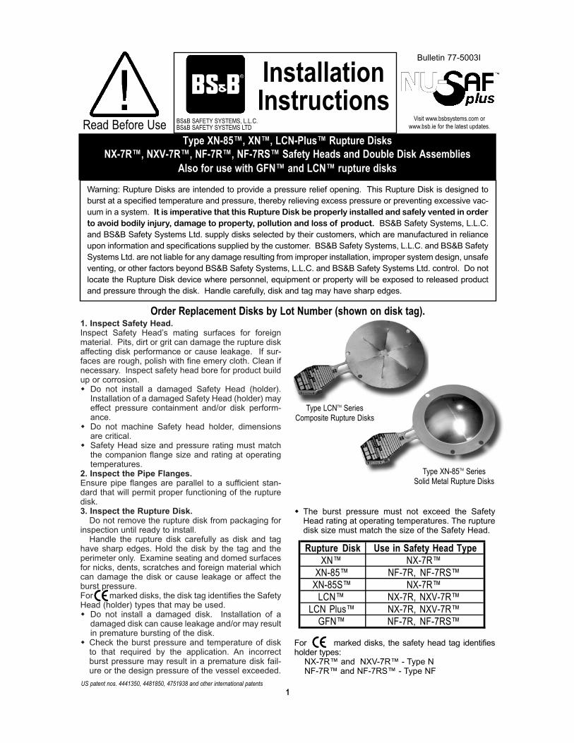
Order Replacement Disks by Lot Number (shown on disk tag).
Rupture Disk Use in Safety Head TypeXN™ NX-7R™
XN-85™ NF-7R, NF-7RS™XN-85S™ NX-7R™
LCN™ NX-7R, NXV-7R™LCN Plus™ NX-7R, NXV-7R™
GFN™ NF-7R, NF-7RS™
Visit www.bsbsystems.com orwww.bsb.ie for the latest updates.
Type XN-85TM Series Solid Metal Rupture Disks
Type LCNTM Series Composite Rupture Disks

� Only competent trained personnel should install rup-ture disk safety devices in accordance with theseinstallation instructions.
� Consider Recoil. Provide adequate support for pipingand connections to absorb recoil /reaction forceswhen the disk ruptures. Recoil is the force the systemwill experience upon disk rupture. Recoil (lbs.) isapproximately twice the disk’s burst pressure (psig)times the relief area (in2). If the discharge is freevented a baffle plate may be mounted downstream ofthe outlet companion pipe flange with extra lengthstuds to minimize recoil.
� If disks are liquid or steam cleaned and a high veloc-ity particle spray or jet is used, take care not to dam-age the disk.
� Where a disk is mounted upstream of a pressurerelief valve or safety valve ensure that the opening ofthe disk does not interfere or effect the performanceof the valve.
� Where a disk is mounted upstream of a pressurerelief valve or safety valve ensure that a means isprovided to prevent pressure build-up in inter-spacein event of disk leakage.
� When a disk ruptures, ensure that the opening of thedisk does not affect the performance of downstreamequipment. The bursting of the disk may result in apressure shock wave.
� The Rupture Disk and Safety Head must not be mod-ified in any way except with the approval of BS&BSafety Systems, L.L.C or BS&B Safety Systems Ltd.Un-approved modification may effect pressure con-tainment and/or disk performance. Failure to obtain
such approval voids the warranty on this product.� The Rupture Disk and Safety Head material must be
compatible with your process. � Corrosion and process conditions may deteriorate
disk performance and necessitate replacement.� Do not reinstall a disk that has been removed from
the piping system unless used in a pre-torquedSafety Head (NF-7RS™). Removing the rupture diskfrom the Safety Head relieves the stresses in thedisk, the disk can never resume its original installedcondition, which may prevent sealing and effect diskperformace if re-installed.
� The burst pressure of a rupture disk is effected bytemperature. Ensure that the disk burst pressurevariation due to temperature is compatible with thesystem operating pressure and temperature condi-tions.
� A rupture disk is a differential pressure sensitivedevice. Where a back-pressure exists on a disk, thismust be considered during the specification of therupture disk burst pressure.
� Ensure gasket materials adequate for the serviceconditions including the ability of the gasket to resist"cold flow". Gaskets that cold flow will allow torquerelaxation which may prevent sealing and effect diskperformance.
l (The burst pressure of disks installed in pre-torquedSafety Heads, NF-7RS™ is un-affected.)� Do not locate the disk where it may be subjected to
thermal shock. Moisture, rain, condensation or snowmay cause a thermal shock to the disk causing thedisk to burst below its rated pressure.
Flow direction
Outlet
CapscrewRupture Disk
Flow direction
Installation of Rupture Disk in a Quik-Sert™ Safety Head.Safety Head Types : NX-7R™, NXV-7R™ & NF-7R™
1. Place inlet of Safety Head on a work surface in posi-tion shown in diagram with flow arrows and locationpins up.
2. Place NEW, UNDAMAGED rupture disk on inletflange so locating pins mate with the correspondingholes in the rupture disk. Flow arrows on disk tagshould indicate direction of flow.
3. Carefully align and place outlet flange in position asshown.Ensure flow arrows on the disk tag and on theSafety Head point in the same direction.
4. Assemble unit with alignment lugs and capscrews. Tighten capscrews only sufficiently to hold disk snug-ly in place between the two flanges.
Note: The type NXV-7R™ Safety Head (Figure 1A) has anintegral dial vacuum support in the inlet flange The NXV-7R™ Safety Head is recommended for usewith type LCN™, LCN Plus™ disks ONLY.The free flow area will be reduced to Net Flow Areastamped on the Safety Head tag.
Figure 1Type NX-7R™ Safety Head
For types XN™, LCN™, LCN Plus™, XN-85S™ disks
Figure 1AType NXV-7R™ Safety Head with integral dial vacuum support
For types LCN™, LCN Plus™ rupture disks only
Inlet
Locating Pins
Lug andCapscrew
Flow Arrow
Outlet
CapscrewRupture Disk
Inlet
Locating Pins
Lug and Capscrew
Flow Arrow
Safety Precautions - Caution
2

1. Insert Safety Head assembly into pressure systembetween companion pipe flanges. The Quik-Sert™centers inside the bolting pattern of pipe flanges. (Refer to Figure 2). Ensure flow arrows on disk tag and Safety Headpoint in desired flow direction upon disk rup-ture.
Note: The NF-7R™ is fitted with a J-Bolt which preventsthe Safety Head from being installed incorrectlywith respect to flow (see Figure 3). The inlet com-panion flange must be radially drilled to accept theJ-Bolt. Table D lists companion flange drillingdimensions. Locate the J-Bolt in the drilled hole.Do not remove or damage the J-Bolt.
2. Install gaskets between Quik-Sert™ Safety Headand companion pipe flanges. A hard compressedfibre gasket of 1/16” (1.6mm) or 1/8” (3mm) thick isrecommended.
CAUTION:Ensure gasket materials are adequate for the serv-ice conditions including the ability of the gasket toresist “cold flow”. Gaskets that cold flow will allowtorque relaxation which may prevent sealing andeffect disk performance.Contact BS&B Safety Systems, L.L.C or BS&BSafety Systems Ltd if an alternative gasket typeis used, or for advice on the use of spiral woundgaskets.
3. Install studs with nuts which should be free-runningwith lightly oiled threads. Tighten all nuts fingertight.
4. Torque the nuts to value shown in Table A. Torqueevenly in a diagonal pattern by applying 1/4 of rec-ommended torque to each stud. Repeat pattern bytorquing to 3/4 of recommended torque value.Then using same pattern torque to full-specifiedtorque value. Do not exceed the specified torquevalue.
CAUTION:Uneven or under-torquing can cause leakageand/or may effect burst pressure. Excessivetorquing can damage the disk and Safety Head.
5. The torque value on the companion flange nutsshould be verified periodically at the system servicetemperature.
Note:All torque values are for compressed fibre gaskets.
WARNING:Should the NXV-7R™ safety head be installedupside down, the rupture disk can not function torelieve pressure. The design pressure of the vesselmay be exceeded.
Installation of Quik-Sert™ Safety Head in Pressure System(Please note that Quik-Sert™ Safety Heads are not pre-torqued holders)
NX-7R™ INSTALLEDBETWEEN COMPANION
PIPE FLANGEThe NX-7R™ nestles
inside the bolting patternof pipe flanges.
NF-7R™ INSTALLEDBETWEEN COMPAN-
ION PIPE FLANGEThe NF-7R™ nestles
inside the bolting patternof pipe flanges.
Figure 2 Figure 3
3

IN MM ANSI CL
DIN PNAND
BS45043.1 PN
JIS PN BS 10TABLE
FT-LBS NM FT-LBS NM
1 25 150 10/16 - D/E 20 27 20 271 25 - - 10/16/20 - 25 34 25 341 25 - 25/40 - - - - 20 271 25 300/600 - - F - - 40 541 25 - - 30/40 - - - 25 34
1 1/2 40 150 - - D/E 20 27 25 341 1/2 40 - 10/16 10/16/20 - 25 34 32 431 1/2 40 - 25/40 - F - - 46 621 1/2 40 300/600 - - - - - 80 1081 1/2 40 - - 30/40 - - 90 122
2 50 150 10/16 10 D/E 40 54 40 542 50 - - 16 - 25 34 46 622 50 - 25/40 20/30/40 F - - 46 622 50 300/600 - - - - - 40 543 80 150 - - D/E 40 54 50 683 80 - 10/16 10 - 20 27 25 343 80 - - 16 - 60 80 90 1223 80 - 25/40 - F - - 46 623 80 300 - - - - - 80 1083 80 - - 20/30/40 - - - 90 1224 100 150 10/16 10 F 40 54 45 614 100 - - - D/E 50 68 50 684 100 - - 16 - 50 68 90 1224 100 300 25/40 20 - - - 90 1224 100 - - 30/40 - - - 124 1686 150 150 10/16 10 E 80 108 95 1296 150 - - 16/20 - 92 125 124 1686 150 - - - D 50 68 50 686 150 - 25/40 30 - - - 155 2106 150 300 - - F - - 95 1296 150 - - 40 - - - 230 3118 200 150 10 - E 80 108 95 1298 200 - 16 10/16/20 F - - 64 868 200 - 25 30 - - - 140 1898 200 - 40 40 - - - 157 2128 200 - - - D 50 68 50 688 200 300 - - - - - 122 165
10 250 150 - - F 100 136 125 17010 250 300 - - - - - 188 25510 250 - 10 - - - - 92 12410 250 - 16 - - - - 149 20210 250 - 25 - - - - 235 31810 250 - 40 40/30 - - - 317 42910 250 - - 10 - - - 103 14010 250 - - 16/20 - - - 158 21510 250 - - - D/E - - 77 105
SAFETY HEAD COMPANION FLANGERATING
COMPANION FLANGE STUD TORQUEDISK MATERIAL
ALUMINUM OTHERDISK SIZE
Notes: The above torque values are suitable for use withstuds of a minimum design stress of 25,000 psi asdefined in ASME, Section II. Table 3. The companionflanges must be compatible for use with stud stresses upto 25,000 psi.
Consult BS&B Safety Systems, L.L.C or BS&B SafetySystems Ltd for flanges in other materials, when suppli-ers recommended torque values are lower than theBS&B recommended values and if gasket type differsfrom BS&B Safety Systems, L.L.C or BS&B Safety
4
Table A (continued on next page)
NX-7R™ / NXV-7R™ / NF-7R™ Safety Head and Double Disk Assemblies Companion Flange Torques
Systems Ltd recommendations.The torque values in the table above are based on theassumption of lightly oiled, clean, free running threadswith a coefficient of friction of m = 0.16 ~ 0.20. The cus-tomer is advised that the affects of corrosion, the use ofparticular thread compounds or dry assembly may resultin a change in the effective clamp load on the diskassembly. This may adversely affect the performance ofthe disk.

IN MM ANSI CL
DIN PNAND
BS45043.1 PN
JIS PN BS 10TABLE
FT-LBS NM FT-LBS NM
12 300 150 - - E/F 110 149 125 17012 300 300 - - - - - 266 36012 300 - 16 16/20 - - - 158 21512 300 - 25 - - - - 235 31812 300 - 40 30 - - - 317 42912 300 - - 40 - - - 556 75312 300 - - - D - - 77 10514 350 150 - - F - - 188 25514 350 300 - - - - - 266 36014 350 - 10 - - - - 92 12414 350 - 16 - - - - 158 21514 350 - 25 - - - - 317 42914 350 - 40 30 - - - 434 58914 350 - - 40 - - - 556 75314 350 - - 16/20 - - - 308 41814 350 - - - D/E - - 125 17016 400 150 - - F - - 188 25516 400 300 - - - - - 378 51216 400 - 10 10 - - - 158 21516 400 - 16 - - - - 235 31816 400 - 25 - - - - 434 58916 400 - 40 30/40 - - - 556 75316 400 - - 16/20 - - - 317 42916 400 - - - D/E - - 125 17018 450 150 - - F - - 266 36018 450 300 - - - - - 378 51218 450 - 10 - - - 158 21518 450 150 - 16/20 - - - 317 42918 450 300 - - D/E - - 125 17020 500 150 - - - - - 266 36020 500 300 - - - - - 378 51220 500 - 10 - - - - 158 21520 500 - 16 16/20 - - - 317 42920 500 - 25 - - - - 434 58920 500 - 40 - - - - 724 98120 500 - - - D/E - - 156 21220 500 - - - F - - 332 45024 600 150 - - - - - 378 51224 600 300 - - - - - 660 89424 600 - 16 - - - - 434 58924 600 - 25 16/20 - - - 556 75324 600 - - - D - - 235 31824 600 - - - E - - 332 45024 600 - - - F - - 473 641
DISK SIZE SAFETY HEAD COMPANION FLANGERATING
COMPANION FLANGE STUD TORQUEDISK MATERIAL
ALUMINUM OTHER
TABLE A (continued)
NX-7R™ / NXV-7R™ / NF-7R™ Safety Head and Double Disk AssembliesCompanion Flange Torques
Notes: The above torque values are suitable for use withstuds of a minimum design stress of 25,000 psi asdefined in ASME, Section II. Table 3. The companionflanges must be compatible for use with stud stresses upto 25,000 psi.
Consult BS&B Safety Systems, L.L.C or BS&B SafetySystems Ltd for flanges in other materials, when suppli-ers recommended torque values are lower than theBS&B recommended values and if gasket type differsfrom BS&B Safety Systems, L.L.C or BS&B Safety
Systems Ltd recommendations.The torque values in the table above are based on theassumption of lightly oiled, clean, free running threadswith a coefficient of friction of m = 0.16 ~ 0.20. The cus-tomer is advised that the affects of corrosion, the use ofparticular thread compounds or dry assembly may resultin a change in the effective clamp load on the diskassembly. This may adversely affect the performance ofthe disk.
5

effect disk performance. (The burst pressure of disksinstalled in pre-torquable Safety Heads NF-7RSTM isunaffected.)Contact BS&B Safety Systems, L.L.C or BS&BSafety Systems Ltd if an alternative gasket typeis used, or for advice on the use of spiral woundgaskets.
3. Install studs with nuts. Studs with nuts should be freerunning with lightly oiled threads, see Table F forstud details. Tighten all nuts finger tight. Torque thenuts to the value shown in Table G. Torque evenly ina diagonal pattern by applying 1/4 of the recom-mended torque to each stud. Repeat pattern bytorquing to 1/2 then 3/4 of the recommended torquevalue. Then using same pattern, torque to full torquevalue. Do not exceed the specified torque value.CAUTION: Uneven or under-torquing can cause leakage and/ormay effect burst pressure. Excessive torquing candamage the disk and Safety Head.
4. The torque value on the companion flange nuts shouldbe verified periodically.
1. Place inlet of Safety head on a flat work surface in positionas shown with flow arrows and locating pins up. (Pleaserefer to the drawing in Figure 5 that corresponds to thenominal disk size and Safety Head rating to be installed).
2. Place NEW, UNDAMAGED, rupture disk on inlet solocating pins mate with the corresponding holes in therupture disk flange.
3. Carefully align and place Safety Head outlet flange in posi-tion as shown.Ensure flow arrows on the disk tag and on the SafetyHead point in the same direction
4. Assemble unit with twelve point capscrews. Tighten thetwelve point high strength capscrews with socket (Seetorque table as identified in these instructions for sockettype) finger tight before torquing. DO NOT SUBSTI-TUTE for capscrews supplied. Do not lubricate blue fluo-ropolymer coated capscrews.
5. Evenly torque the capscrews to the value shown in TableB when using uncoated capscrews or Table C when usingblue colour fluoropolymer coated capscrews. Torque
1. Insert the Safety Head assembly into the pressuresystem between companion flanges. Ensure flow arrows on the Safety Head and disktag point in the desired flow direction upon diskrupture.The NF-7RS™ centers inside the bolting pattern ofpipe flanges, see Figure 6 and a J-Bolt prevents theSafety Head from being installed incorrectly withrespect to flow, see Figure 4. The inlet companionflange must be radially drilled to accept the J-Bolt.Table E list companion flange drilling dimensions.Locate the J-Bolt in the drilled hole. Do not removeor damage the J-Bolt.
2. Install gaskets between the Safety Head and thecompanion flanges. A hard compressed fibre gasketof 1/16” (1.6mm) or 1/8” (3mm) thick is recommend-ed. CAUTION: Ensure gasket materials are adequate for the serv-ice conditions including the ability of the gasket toresist "cold flow". Gaskets that cold flow will allowtorque relaxation which may prevent sealing and
evenly in a diagonal pattern by applying 1/4 of the torquevalue to capscrew (1), and then applying torque to (2), (3)and (4) etc. Repeat the torquing pattern for 1/2 then 3/4 of the recommended torque value. Finally using same pat-tern, torque to full torque value.CAUTION:Uneven or under-torquing can cause leakage and/or mayeffect burst pressure. Excessive torquing can damage thedisk and Safety Head.Note: Use the correct socket and torque wrench withappropriate torque value range. The torque wrench mustbe calibrated.
6. The twelve point capscrew heads should be recessed intothe NF-7RS™ Safety Head outlet after installation.
7. Safety Heads have a ‘bite type’ seal on the inlet face thatengages with the rupture disk. Do not modify this featurein any way. Should the ‘bite type’ seal be incomplete ordamaged contact BS&B Safety Systems, L.L.C, or BS&BSafety Systems Ltd for repair.
Installation of Rupture Disk in NF-7RS™ Safety HeadU.S. patent no. 4,751,938 and other international patents apply.
Installation of Safety Head NF-7RS™ Assembly in Pressure System
Figure 4: Inlet Companion Flange Drilling to Accept J-Bolt
‘A’
‘B’
‘Z’
22 1/2°
Drill Ø ‘C’ x ‘B’deep x ‘A’ from flange face betweencompanion flange bolt holes as shown
‘Z’
6

Figure 5Type NF-7RS™ Safety Head
Flow direction
Outlet
Capscrews1
3 2
4
Inlet
Locating Pins
Rupture Disk
Rupture Disk
Rupture Disk
J-Bolt
Outlet
Capscrews1
32
4
Inlet
Locating Pins
J-Bolt
Flowdirection
Outlet
Capscrews1
32
4
857 6
Inlet
Locating Pins
J-Bolt
1” (25mm) ANSI 150/300/600/9001.5” (40mm) DIN 10/16/25/40
JIS 10/16/20/30/40
2” (50mm) ANSI 900
2” (50mm) ANSI 150/300/6003” (80mm) DIN 10/16/25/404” (100mm) JIS 10/16/20/30/40
except for4” (100mm) ANSI 600
6” (150mm) ANSI 150/300DIN 10/16/25/40JIS 10/16/20/30/40
8” (200mm) ANSI 150/300DIN 10
{
{
Flow direction
7

IN MM ANSI CL DIN JIS FT-LBS. NT-M FT-LBS. NT-M1 25 150 10/16 10/16 11 15 17 23 1/4 3/8 STMD-81 25 300/600 25/40 20/30/40 - - 17 23 1/4 3/8 STMD-81 25 900/1500 - - - - 60 81 3/8 3/8 SF-121
1.5 40 150 10/16 10/16 24 33 30 41 5/16 1/4 STMD-101.5 40 300/600 25/40 20/30/40 - - 30 41 5/16 1/4 STMD-101.5 40 900/1500 - - - - 65 88 3/8 3/8 SF-1212 50 150 10/16 10/16 26 35 34 46 5/16 1/4 STMD-102 50 300/600 25/40 20/30/40 - - 34 46 5/16 1/4 STMD-102 50 900/1500 - - - - 100 136 1/2 3/8 SF-1613 80 150 10/16 10/16 41 55 65 88 3/8 3/8 SF-1213 80 300/600 25/40 20/30/40 - - 65 88 3/8 3/8 SF-1214 100 150 10/16 10/16 75 102 102 138 7/16 3/8 SF-1414 100 300 25/40 20/30/40 - - 102 138 7/16 3/8 SF-1414 100 600 - - - - 65 88 3/8 3/8 SF-1216 150 150 10/16 10/16 47 64 60 81 3/8 3/8 SF-1216 150 300 25/40 20/30/40 - - 60 81 3/8 3/8 SF-1216 150 600 - - - - 102 138 7/16 3/8 SF-1418 200 150 10 - 70 95 84 114 7/16 3/8 SF-1418 200 300 - - - - 84 114 7/16 3/8 SF-14110 250 150 - - 55 74 70 95 7/16 3/8 SF-14110 250 300 - - - - 70 95 7/16 3/8 SF-14112 300 150 - - 22 30 29 39 5/16 3/8 SF-10112 300 300 - - - - 50 68 7/16 3/8 SF-14116 400 150 - - - - 80 108 7/16 3/8 SF-14116 400 300 - - - - 195 264 5/8 1/2 SW-20118 460 150 - - - - 120 163 1/2 1/2 SW-16118 460 300 - - - - 195 264 5/8 1/2 SW-20120 500 150 - - - - 120 163 1/2 1/2 SW-16120 500 300 - - - - 195 264 5/8 1/2 SW-20124 600 150 - - - - 195 264 5/8 1/2 SW-20124 600 300 - - - - 350 475 3/4 1/2 SW-241
SIZE SAFETY HEAD COMPANIONFLANGE RATING
PREASSEMBLY CAPSCREW TORQUE 12 POINTSOCKET
SIZE
SOCKETDRIVE
*
SUGGESTEDSOCKET SOURCESNAP-ON TOOLS
ALUMINUM OTHER MATERIAL
Table B - Uncoated CapscrewsNF-7RS™ Safety Head and Double Disk Assembly Preassembly Capscrew Torque
Notes:* 12 point, deep length, thin wall socketThe torque values in the in the table above arebased on the assumption of lightly oiled, clean, freerunning threads with a coefficient of friction of m =0.16 ~ 0.20. The affects of corrosion, the use ofthread compounds, or dry assembly may result in achange in the effective clamp load on the diskassembly. This may adversely affect the perform-ance of the disk. Snap-on® is a registered trademarkof Snap-On Technologies Incorporated.
8

Table C - Blue Coated CapscrewsNF-7RS™ Safety Head and Double Disk Assembly Preassembly Capscrew Torque
Blue Coated Capscrews, Max Temperature 500ºF (260ºC)
IN MM ANSI CL DIN JIS FT-LBS. NT-M FT-LBS. NT-M1 25 150 10/16 10/16 6 8 9 12 1/4 3/8 STMD-81 25 300/600 25/40 20/30/40 - - 9 12 1/4 3/8 STMD-81 25 900/1500 - - - - 30 41 3/8 3/8 SF-121
1.5 40 150 10/16 10/16 12 17 15 20 5/16 1/4 STMD-101.5 40 300/600 25/40 20/30/40 - - 15 20 5/16 1/4 STMD-101.5 40 900/1500 - - - - 33 45 3/8 3/8 SF-1212 50 150 10/16 10/16 13 18 17 23 5/16 1/4 STMD-102 50 300/600 25/40 20/30/40 - - 17 23 5/16 1/4 STMD-102 50 900/1500 - - - - 50 68 1/2 3/8 SF-1613 80 150 10/16 10/16 21 28 33 45 3/8 3/8 SF-1213 80 300/600 25/40 20/30/40 - - 33 45 3/8 3/8 SF-1214 100 150 10/16 10/16 38 52 51 69 7/16 3/8 SF-1414 100 300 25/40 20/30/40 - - 51 69 7/16 3/8 SF-1414 100 600 - - - - 33 45 3/8 3/8 SF-1216 150 150 10/16 10/16 24 33 30 41 3/8 3/8 SF-1216 150 300 25/40 20/30/40 - - 30 40 3/8 3/8 SF-1216 150 600 - - - - 51 69 7/16 3/8 SF-1418 200 150 10 - 35 47 42 57 7/16 3/8 SF-1418 200 300 - - - - 42 57 7/16 3/8 SF-14110 250 150 - - 28 37 35 48 7/16 3/8 SF-14110 250 300 - - - - 35 48 7/16 3/8 SF-14112 300 150 - - 11 15 15 20 5/16 3/8 SF-10112 300 300 - - - - 25 34 7/16 3/8 SF-14116 400 150 - - - - 40 54 7/16 3/8 SF-14116 400 300 - - - - 98 132 5/8 1/2 SW-20118 460 150 - - - - 60 81 1/2 1/2 SW-16118 460 300 - - - - 98 133 5/8 1/2 SW-20120 500 150 - - - - 60 81 1/2 1/2 SW-16120 500 300 - - - - 98 133 5/8 1/2 SW-20124 600 150 - - - - 98 133 5/8 1/2 SW-20124 600 300 - - - - 175 237 3/4 1/2 SW-241
SIZE SAFETY HEAD COMPANIONFLANGE RATING
PREASSEMBLY CAPSCREW TORQUE 12 POINTSOCKET
SIZE
SOCKETDRIVE
*
SUGGESTEDSOCKET SOURCESNAP-ON TOOLS
ALUMINUM OTHER MATERIAL
Notes:* 12 point, deep length, thin wall socketDo not lubricate blue fluoropolymer coated capscrews.Snap-on® is a registered trademark of Snap-OnTechnologies Incorporated.
9

Figure 6NF-7RS™ Safety Heads Inside the Flange Bolting Pattern
1” (25 mm) ANSI 150/300/600/900/1500
DIN 10/16/25/40JIS 10/16/20/30/40
1 1/2” (40mm) ANSI 150/300/600900/1500
DIN 10/16/25/40JIS 10/16/20/30/40
2” (50mm) ANSI 300/600JIS 16/20/30/40
3” (DN80) ANSI 300/600DIN 10/16/25/40JIS 10/16/20/30/40
4” (DN100) ANSI 150/300DIN 10/16/25/40JIS 10/16/20/30/40
2” (50mm) ANSI 150JIS 10
2” (50mm) DIN 10/16/25/403” (80mm) ANSI 150
2” (80mm) ANSI 900/1500 6” (150mm) ANSI 150DIN 10/16/25/40JIS 10
8” (200mm) ANSI 150DIN 10
6” (150mm) ANSI 300JIS 16/20/30/40
8” (200mm) ANSI 300
NF-7RS™ InstalledIn companion flange
J-Bolt
10
10” (250mm) ANSI 150For larger sizes, configuration is similar to8” and 10”.

11
IN ± 1/32 MM ± 0.8 IN + 1/16 - 0 MM + 1.6 - 0 IN MM150 5/16 8 1/2 13 7/16 11300 7/16 11 7/16 11 7/16 11600 7/16 11 7/16 11 7/16 11
900/1500 7/8 22 5/8 16 7/16 11150 7/16 11 1/2 13 7/16 11300 1/2 13 7/16 11 7/16 11600 1/2 13 7/16 11 7/16 11
900/1500 7/8 22 5/8 16 7/16 11150 1/2 13 1/2 13 7/16 11300 1/2 13 5/8 16 7/16 11600 1/2 13 5/8 16 7/16 11
900/1500 7/8 22 3/4 19 7/16 11150 5/8 16 1/2 13 7/16 11300 5/8 16 7//8 22 7/16 11600 5/8 16 5/8 16 7/16 11900 5/8 16 1 25 7/16 11150 11/16 17.5 1/2 13 7/16 11300 3/4 19 1/2 13 7/16 11600 3/4 19 1/2 13 7/16 11900 3/4 19 1 25 7/16 11150 3/4 19 1/2 13 7/16 11300 3/4 19 5/8 16 7/16 11600 3/4 19 5/8 16 7/16 11900 3/4 19 1 25 7/16 11150 5/8 16 1/2 13 5/8 16300 5/8 16 1 1/4 32 5/8 16600 5/8 16 1 25 5/8 16150 13/16 20 1/2 13 5/8 16300 13/16 20 1 1/4 32 5/8 16600 13/16 20 1 25 5/8 16150 13/16 20 5/8 16 5/8 16300 13/16 20 1 3/8 35 5/8 16600 13/16 20 1 25 5/8 16
12"
4"
6"
8"
10"
1"
1 1/2"
2"
3"
SIZEANSI
FLANGERATING
NF-7RA B C
Table DNF-7R™ Safety Head and Double Disk Assembly Companion Flange
J-Bolt Drilling Dimensions
Consult BS&B Safety Systems, L.L.C. or BS&B Safety Systems Ltd for other sizes and ratings.

IN MM ANSI DIN JIS IN ± 1/32 MM ± .8 IN + 1/16 - 0 MM + 1.6 - 0 IN MM1 25 150 - - 5/16 8 7/16 11 7/16 111 25 - 10/16 - 13/32 10 5/16 8 7/16 111 25 - - 10/16 9/32 7 35/64 14 7/16 111 25 300 - - 7/16 11 1/2 13 7/16 111 25 - 25 - 13/32 10 5/16 8 7/16 111 25 - - 20 9/32 7 5/8 16 7/16 111 25 600 - - 9/16 14.5 5/8 16 7/16 111 25 - 40 - 13/32 10 35/64 14 7/16 111 25 - - 30/40 13/32 10 6/8 16 7/16 11
1.5 40 150 - - 3/8 9.5 7/16 11 7/16 111.5 40 - 10/16 - 13/32 10 13/32 10 7/16 111.5 40 - - 10/16/20 11/32 9 5/8 16 7/16 111.5 40 300 - - 1/2 13 1/2 13 7/16 111.5 40 - 25/40 - 13/32 10 13/32 10 7/16 111.5 40 - - 30/40 7/16 11 19/32 15 7/16 111.5 40 600 - - 9/16 14.5 1/2 13 7/16 112 50 150 - - 1/2 13 7/16 11 7/16 112 50 - - 10/16/20 13/32 10 7/16 11 7/16 112 50 - 10/16/25/40 15/32 12 19/32 15 7/16 112 50 - - 30/40 15/32 12 5/8 16 7/16 112 50 300/600 - - 9/16 14.5 11/16 17.5 7/16 113 80 150 - - 11/16 17.5 7/16 11 7/16 113 80 - - 10 13/32 10 13/32 10 7/16 113 80 - 10/16/25/40 - 15/32 12 13/32 10 1/2 133 80 - - 16/20 1/2 13 11/32 9 7/16 113 80 300/600 - 3/4 19 13/16 20.5 7/16 113 80 - - 30/40 1/2 13 19/32 15 7/16 114 100 150 - - 11/16 17.5 9/16 14.5 7/16 114 100 - 10/16 - 15/32 12 13/32 10 19/32 154 100 - - 10 13/32 10 13/32 10 7/16 114 100 300 - - 3/4 19 1-1/6 27 7/16 114 100 - 25/40 - 15/32 12 23/32 18 19/32 154 100 - - 16/20 19/32 15 1/2 13 7/16 114 100 600 - 3/4 19 9/16 14.5 7/16 114 100 - - 30 19/32 15 25/32 20 7/16 114 100 - - 40 19/32 15 1-1/32 26 7/16 116 150 150/600 - - 3/4 19 9/16 14.5 7/16 116 150 - 10/16 - 15/32 12 7/16 11 5/8 166 150 - - 10 35/64 14 5/16 8 7/16 116 150 - - 16/20 13/32 10 15/32 12 7/16 116 150 300 - - 3/4 19 1-5/16 33.5 7/16 116 150 - 25/40 - 15/32 12 3/4 19 5/8 166 150 - - 30 43/64 17 1-3/16 30 7/16 116 150 - - 40 43/64 17 1-49/64 45 7/16 118 200 150 - - 5/8 16 1/2 13 5/8 168 200 300 - - 5/8 16 1-1/4 32 5/8 1610 250 150 - - 5/8 16 1/2 13 5/8 1610 250 300 - - 5/8 16 1-1/4 32 5/8 1612 300 150/300 - - 5/8 16 5/8 16 5/8 1616 400 150 - - 5/8 16 3/8 9.5 11/16 17.516 400 300 - - 5/8 16 1/2 13 11/16 17.518 460 150 - - 5/8 16 1/2 13 11/16 17.518 460 300 - - 5/8 16 9/16 14.5 11/16 17.520 500 150 - - 5/8 16 5/8 16 11/16 17.520 500 300 - - 5/8 16 5/8 16 11/16 17.524 600 150 - - 5/8 16 11/16 17.5 11/16 17.524 600 300 - - 5/8 16 1 25.5 11/16 17.5
SIZE COMPANION FLANGE RATING DIMENSIONSA B C
Table ENF-7RS™ Safety Head Companion Flange J-Bolt Drilling Dimensions
12
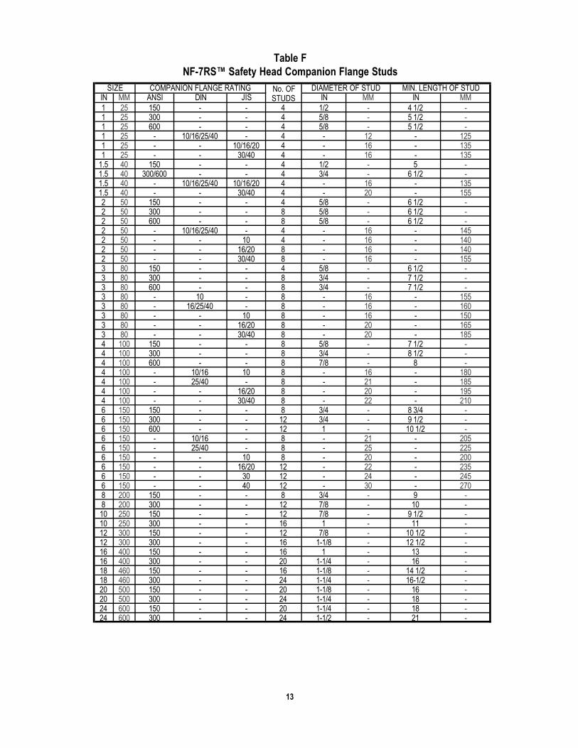
IN MM ANSI DIN JIS IN MM IN MM1 25 150 - - 4 1/2 - 4 1/2 -1 25 300 - - 4 5/8 - 5 1/2 -1 25 600 - - 4 5/8 - 5 1/2 -1 25 - 10/16/25/40 - 4 - 12 - 1251 25 - - 10/16/20 4 - 16 - 1351 25 - - 30/40 4 - 16 - 135
1.5 40 150 - - 4 1/2 - 5 -1.5 40 300/600 - - 4 3/4 - 6 1/2 -1.5 40 - 10/16/25/40 10/16/20 4 - 16 - 1351.5 40 - - 30/40 4 - 20 - 1552 50 150 - - 4 5/8 - 6 1/2 -2 50 300 - - 8 5/8 - 6 1/2 -2 50 600 - - 8 5/8 - 6 1/2 -2 50 - 10/16/25/40 - 4 - 16 - 1452 50 - - 10 4 - 16 - 1402 50 - - 16/20 8 - 16 - 1402 50 - - 30/40 8 - 16 - 1553 80 150 - - 4 5/8 - 6 1/2 -3 80 300 - - 8 3/4 - 7 1/2 -3 80 600 - - 8 3/4 - 7 1/2 -3 80 - 10 - 8 - 16 - 1553 80 - 16/25/40 - 8 - 16 - 1603 80 - - 10 8 - 16 - 1503 80 - - 16/20 8 - 20 - 1653 80 - - 30/40 8 - 20 - 1854 100 150 - - 8 5/8 - 7 1/2 -4 100 300 - - 8 3/4 - 8 1/2 -4 100 600 - - 8 7/8 - 8 -4 100 - 10/16 10 8 - 16 - 1804 100 - 25/40 - 8 - 21 - 1854 100 - - 16/20 8 - 20 - 1954 100 - - 30/40 8 - 22 - 2106 150 150 - - 8 3/4 - 8 3/4 -6 150 300 - - 12 3/4 - 9 1/2 -6 150 600 - - 12 1 - 10 1/2 -6 150 - 10/16 - 8 - 21 - 2056 150 - 25/40 - 8 - 25 - 2256 150 - - 10 8 - 20 - 2006 150 - - 16/20 12 - 22 - 2356 150 - - 30 12 - 24 - 2456 150 - - 40 12 - 30 - 2708 200 150 - - 8 3/4 - 9 -8 200 300 - - 12 7/8 - 10 -10 250 150 - - 12 7/8 - 9 1/2 -10 250 300 - - 16 1 - 11 -12 300 150 - - 12 7/8 - 10 1/2 -12 300 300 - - 16 1-1/8 - 12 1/2 -16 400 150 - - 16 1 - 13 -16 400 300 - - 20 1-1/4 - 16 -18 460 150 - - 16 1-1/8 - 14 1/2 -18 460 300 - - 24 1-1/4 - 16-1/2 -20 500 150 - - 20 1-1/8 - 16 -20 500 300 - - 24 1-1/4 - 18 -24 600 150 - - 20 1-1/4 - 18 -24 600 300 - - 24 1-1/2 - 21 -
MIN. LENGTH OF STUDSIZE COMPANION FLANGE RATING No. OFSTUDS
DIAMETER OF STUD
Table FNF-7RS™ Safety Head Companion Flange Studs
13

14
IN MM ANSI DIN JIS FT-LB NT-M FT-LB NT-M1 25 150 10/16 - 20 27 20 271 25 - - 10/16/20 25 34 25 341 25 - 25/40 - - - 20 271 25 300/600 - - - - 40 541 25 - - 30/40 - - 25 341 25 900/1500 - - - - 122 165
1 1/2 40 150 - - 20 27 25 341 1/2 40 - 10/16 10/16/20 25 34 46 621 1/2 40 300/600 - - - - 80 1081 1/2 40 - 25/40 - - - 46 621 1/2 40 - - 30/40 - - 90 1221 1/2 40 900/1500 - - - - 182 247
2 50 150 - - 40 54 40 542 50 - 10/16 10 40 54 46 622 50 - - 16 25 34 46 622 50 300/600 - - - - 40 542 50 - 25/40 20/30/40 - - 46 622 50 900/1500 - - - - 122 1653 80 150 - - 40 54 50 683 80 - 10/16 10 40 54 46 623 80 - - 16 60 80 90 1223 80 300/600 - - - - 80 1083 80 - 25/40 - - - 46 623 80 - - 20/30/40 - - 90 1224 100 150 - - 40 54 45 614 100 - 10/16 40 54 46 624 100 - - 10 40 54 53 754 100 - - 16 50 68 90 1224 100 300 25/40 20 - - 90 1224 100 600 - - - - 120 1634 100 - - 30/40 - - 124 1686 150 150 - - 80 108 95 1296 150 - 10/16 - 84 114 90 1226 150 - - 10 84 114 110 1496 150 - - 16/20 92 125 124 1686 150 300 - - - - 80 1086 150 600 - - - - 180 2446 150 - 25/40 30 - - 155 2106 150 - - 40 - - 230 3128 200 150 10 - - - 75 1028 200 300 - - - - 122 16510 250 150 - - - - 122 16510 250 300 - - - - 182 24712 300 150 - - - - 122 16512 300 300 - - - - 272 36916 400 150 - - - - 185 25116 400 300 - - - - 385 52218 460 150 - - - - 270 36618 460 300 - - - - 385 52220 500 150 - - - - 270 36620 500 300 - - - - 385 52224 600 150 - - - - 385 52224 600 300 - - - - 700 949
SIZE COMPANION FLANGERATING
FLANGE STUD TORQUEALUMINUM OTHER MATERIAL
Table GNF-7RS™ Safety Head and Double Disk Assembly Companion Flange Torque
Notes:The torque values are suitable for use withstuds of a minimum design stress of 25,000psi as defined in ASME, Section II. Table 3.The companion flanges must be compatiblefor use with stud stresses up to 25,000 psi.
Consult BS&B Safety Systems, L.L.C orBS&B Safety Systems Ltd for flanges inother materials, when suppliers recom-mended torque values are lower than theBS&B recomended value and if gasket typediffers from BS&B Safety Systems, L.L.C orBS&B Safety Systems Ltd recommenda-tions.
The torque values in the table above arebased on the assumption of lightly oiled,clean, free running threads with a coeffi-cient of friction of m = 0.16 ~ 0.20. The cus-tomer is advised that the affects of corro-sion, the use of particular thread com-pounds or dry assembly may result in achange in the effective clamp load on thedisk assembly. This may adversely affectthe performance of the disk.
Mid Flange
Mid Flange
Mid Flange
Rupture Disk
Rupture Disk
Rupture Disk
Rupture Disk
Rupture Disk
Rupture Disk
Locating Pins
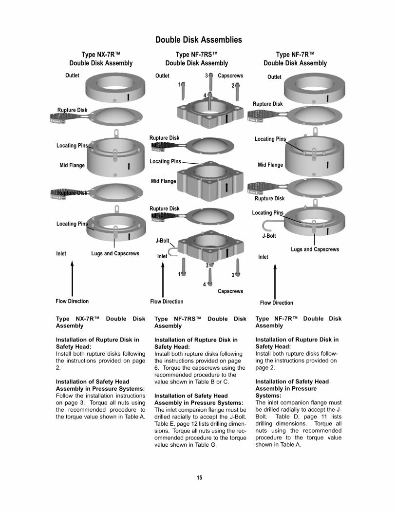
Type NX-7R™ Double DiskAssembly
Installation of Rupture Disk inSafety Head:Install both rupture disks followingthe instructions provided on page2.
Installation of Safety HeadAssembly in Pressure Systems:Follow the installation instructionson page 3. Torque all nuts usingthe recommended procedure tothe torque value shown in Table A.
Type NF-7RS™ Double DiskAssembly
Installation of Rupture Disk inSafety Head:Install both rupture disks followingthe instructions provided on page6. Torque the capscrews using therecommended procedure to thevalue shown in Table B or C.
Installation of Safety HeadAssembly in Pressure Systems:The inlet companion flange must bedrilled radially to accept the J-Bolt.Table E, page 12 lists drilling dimen-sions. Torque all nuts using the rec-ommended procedure to the torquevalue shown in Table G.
Type NF-7R™ Double DiskAssembly
Installation of Rupture Disk inSafety Head:Install both rupture disks follow-ing the instructions provided onpage 2.
Installation of Safety HeadAssembly in PressureSystems:The inlet companion flange mustbe drilled radially to accept the J-Bolt. Table D, page 11 listsdrilling dimensions. Torque allnuts using the recommendedprocedure to the torque valueshown in Table A.
Flow Direction
Outlet Outlet OutletCapscrews
Capscrews
Lugs and CapscrewsLugs and Capscrews
1 2
3
4
1 2
3
4
Inlet Inlet Inlet
J-BoltJ-Bolt
Locating Pins
Locating Pins
Locating Pins
Locating Pins
Double Disk Assemblies
Flow Direction Flow Direction
15
Type NX-7R™ Double Disk Assembly
Type NF-7R™ Double Disk Assembly
Type NF-7RS™ Double Disk Assembly

ISO 9001 Quality System Certification
BS&B SAFETY SYSTEMS, L.L.C.BS&B SAFETY SYSTEMS LTD.
16
Limitations of Warranties – BS&B Safety Systems, L.L.C. and BS&B Safety Systems Ltd. warrants their prod-ucts, when properly installed, used and maintained by the original purchaser, against defective workmanshipand materials for a period of twelve (12) months from the date of shipment. Purchaser’s failure to use this prod-uct in strict compliance with all material operating specifications provided to BS&B Safety Systems, L.L.C. orBS&B Safety Systems Ltd. by purchaser prior to BS&B Safety Systems, L.L.C. or BS&B Safety Systems Ltd.production or shipment of this product shall void this warranty. Rupture disks are warranted solely to burst with-in specified pressure ranges at temperatures specified at the time of sale.
Where pressure relief or other products used by Buyer involve multi-part assemblies, each part must be man-ufactured by BS&B Safety Systems, L.L.C. or BS&B Safety Systems Ltd. BS&B Safety Systems, L.L.C. andBS&B Safety Systems Ltd. specifically disclaim any warranties and any and all liability for damages, either director indirect, incidental or consequential, arising from the use of rupture disk assemblies (e.g. rupture disk andrupture disk holder), explosion vent assemblies (e.g. vent and safety frame) or other assemblies not whollycomprised of BS&B Safety Systems, L.L.C. and BS&B Safety Systems Ltd. manufactured products.
BS&B Safety Systems, L.L.C. and BS&B Safety Systems Ltd. do not warrant any article not manufactured byBS&B Safety Systems, L.L.C. or BS&B Safety Systems Ltd. BS&B Safety Systems, L.L.C. and BS&B SafetySystems Ltd. do not warrant this product against loss or damage caused directly or indirectly by improper pres-sure relief system design; by the improper use, maintenance or installation (including improper torque) of thisproduct; or by corrosion erosion or malfunction caused by acids, chemicals, fumes, rust, dirt, debris, thermalshock, shock waves or other external agencies over which BS&B Safety Systems, L.L.C. and BS&B SafetySystems Ltd. have no control.
THE EXPRESSED WARRANTIES HEREIN GIVEN ARE EXCLUSIVE AND IN LIEU OF ALL WARRANTIESEXPRESSED OR IMPLIED, BY OPERATION OF LAW OR OTHERWISE, INCLUDING, WITHOUT LIMITA-TION, ANY IMPLIED WARRANTY OF MERCHANTABILITY OR FITNESS FOR A PARTICULAR PURPOSE.BUYER’S SOLE AND EXCLUSIVE REMEDY FOR BREACH OF ANY WARRANTY SHALL BE, AT BS&B SAFE-TY SYSTEMS, L.L.C.. OR BS&B SAFETY SYSTEMS LTD. OPTION, THE REPAIR OR REPLACEMENT OFTHE PRODUCT, F.O.B. TULSA, OKLAHOMA, OR LIMERICK, IRELAND.
Liability Limitations – BS&B Safety Systems, L.L.C. and BS&B Safety Systems Ltd. manufacture and supplytheir products in reliance upon information and specifications provided by its customers. BS&B Safety Systems,L.L.C. and BS&B Safety Systems Ltd. specifically disclaim any and all liability, of whatever nature, resulting orarising from Buyer’s failure to disclose fully all material operating conditions, design parameters, process com-ponents, or system or vessel requirements, or from any misrepresentations or omissions by Buyer, Buyeragrees to indemnify and hold harmless BS&B Safety Systems, L.L.C. or BS&B Safety Systems Ltd. for all costs,loss, liability or damage arising or resulting from BS&B Safety Systems, L.L.C. or BS&B Safety Systems Ltd.manufacture or supply of this product in accordance with Buyer’s specifications or requirements.
BS&B SAFETY SYSTEMS, L.L.C. OR BS&B SAFETY SYSTEMS LTD. AGGREGATE TOTAL LIABILITY TOBUYER FOR ANY AND ALL LOSS OR DAMAGE ARISING OUT OF BUYER’S USE OF, OR INABILITY TOUSE, THE PRODUCT SHALL IN NO EVENT EXCEED THE PURCHASE PRICE OF THE PRODUCT OR$1,000.00, WHICHEVER IS LESSER, BS&B SAFETY SYSTEMS, L.L.C. OR BS&B SAFETY SYSTEMS LTD.SHALL NOT BE LIABLE FOR PERSONAL INJURY OR PROPERTY DAMAGE ARISING OUT OF BUYER’SPURCHASE, INSTALLATION OR USE OF THE PRODUCT, AND IN NO EVENT SHALL BS&B SAFETY SYS-TEMS, L.L.C. OR BS&B SAFETY SYSTEMS LTD. BE LIABLE FOR SPECIAL, INCIDENTAL, CONSEQUEN-TIAL OR PUNITIVE DAMAGES RESULTING FROM ANY SUCH CAUSES.
BS&B Safety Systems, L.L.C.7455 East 46th Street
Tulsa, OK 74145Telephone: 918-622-5950Facsimile: 918-665-3904
Email: [email protected]
BS&B Safety Systems LtdRaheen Business Park
Raheen, Limerick, IrelandTelephone: +353 61 227022Facsimile: +353 61 227987
Email: [email protected]
BS&B Safety Systems, L.L.C andBS&B Safety Systems Ltd. are here toassist you in providing a safe and efficientwork place. For assistance on installation,audits, training or technical advice, pleasecontact our Customer Service Department.
©2002 BS&B Safety Systems, L.L.C., BS&B Safety Systems Ltd. June 2002
Note: This document is related to ECType examination certificate
BAS01ATEX2038. Any documentchanges must be approved by the TechnicalDirector of BS&B Safety Systems Ltd.