Embed Size (px)
Citation preview

7706-ULF Integrated Fire
Monitoring SystemInstallation, Operation & Programming Manual
AES Corporation285 Newbury StreetPeabody, MA 01960 USATel (978) 535-7310 • Fax (978) 535-7313www.aes-corp.comCopyright 2015-2016 All Rights Reserved Part No. 40-7706-ULF Rev. 2 November 8, 2016

7706-ULF Integrated Fire Monitoring System2
OWNER WARRANTY — AES CORPORATIONLIMITED PRODUCT WARRANTY AND TECHNOLOGY LICENSE
LIMITED PRODUCT WARRANTY:AES Corporation (“AES”) warrants to the original purchaser that each AES Subscriber Product will be free from defects in material and workmanship for five (5) years from date of purchase and all other products purchased from AES including central station receivers and accessories will be warranted for one (1) year from the date of purchase. At no cost to the original purchaser for parts or labor, AES will repair or replace any AES Product or any, part or parts thereof which are judged defective under the terms of this Warranty.
Defective AES Products must be returned to AES directly, provided they are properly packed, postage prepaid. Or exchange may be made through any authorized direct factory representative for any AES Products that are judged defective under the terms of this Warranty. Improper or incorrectly performed maintenance or repair voids this Warranty. This Warranty does not cover replacement parts that are not approved by AES. This Warranty does not apply to any AES Product or any part thereof that has been altered in any way to affect its stability or reliability, or that has been subjected to abuse, misuse, negligence, accident or act of God, or that has had the serial number effaced or removed.
Certain AES Products are designed to operate and communicate with other specified AES Products and certain other specified products, systems or networks authorized or approved by AES, as identified in the applicable AES Product instructions. This Warranty does not apply to any AES Product that is used with any unauthorized or unapproved products, systems or networks, or that has been installed, applied or used in any manner, other than in strict accordance with AES instructions.
AES makes no warranty, express or implied, other than what is expressly stated in this Warranty. If the law of your state provides that an implied warranty of merchantability, or an implied warranty of fitness for particular purpose, or any other implied warranty, applies to AES, then any such implied warranty is limited to the duration of this Warranty.
AES cannot be aware of and is not responsible for the differing values of any property to be protected by its alarm reporting systems. This Warranty does not cover and AES shall not be liable for any defect, incidental or consequential, loss or damage arising out of the failure of any AES Product to operate.
Some states do not allow the exclusion or limitation of the durations of implied warranties or the limitation on incidental or consequential damages, so the above limitations or exclusions may not apply to you.
This Warranty gives you specific legal rights and you may also have other rights that vary from state to state.
TECHNOLOGY LICENSE:Certain AES Products include software, protocols and other proprietary and confidential technology and trade secrets of AES which are incorporated in or provided with AES Products solely for use in conjunction with and in order to operate AES Products (“Licensed Technology”). AES grants the original purchaser a non-exclusive license to use such Licensed Technology solely in connection with the use and operation of AES Products and for no other purpose or use whatsoever. No title or ownership in or to any such Licensed Technology is conveyed by the sale or delivery of any AES Products; all such rights are retained by AES.
AES SERVICE PROCEDURE: Contact AES by phone (978) 535-7310, fax (978) 535-7313 or email ([email protected]) to receive a Return Material Authorization Number. Have the AES part number and serial number ready. Repack equipment in original or equivalent packaging. Inside the box, please include a contact name, telephone number, address and a brief description of the reason for return.
Ship items freight-prepaid to: Repair Services, RMA#__________AES Corporation285 Newbury StreetPeabody, MA 01960 USA
(Contact AES for Return Material Authorization number.)

37706-ULF Integrated Fire Monitoring System
Part No. 40-7706-ULF Rev. 2 November 8, 2016
Table of Contents
1. Introduction
Purpose of This Manual .....................................................................................................................................7
System Overview ...............................................................................................................................................7
Communication Path Configuration ..................................................................................................................9
Sole Path Delivery (Single Reporting) .........................................................................................................12
Single Reporting with Backup ....................................................................................................................12
Dual Delivery Path (Dual Reporting) ..........................................................................................................12
System Features ...............................................................................................................................................13
P-Link Accessories ............................................................................................................................................14
How to Use this Manual ..................................................................................................................................14
Common Terminology .....................................................................................................................................14
Installation Tasks Overview ..............................................................................................................................14
2. Before You Start Installation
System Specifications ......................................................................................................................................16
Cabinet Description ....................................................................................................................................16
Visual Indicators .........................................................................................................................................16
LCD Description ..........................................................................................................................................16
Environmental Specifications...........................................................................................................................16
Model/Available Cabinet Colors ......................................................................................................................16
System Configurations/Appliances ..................................................................................................................17
Electrical Specifications ...................................................................................................................................17
System Size Specifications ...............................................................................................................................17
Mainboard Wiring Specifications .....................................................................................................................18
Circuit Separation .......................................................................................................................................18
Wiring Types...............................................................................................................................................18
Cabinet Dimensions .........................................................................................................................................20
3. Subscriber Antenna Planning and Installation
Antenna Safety Considerations ........................................................................................................................21
Coaxial Cable Options ......................................................................................................................................22
Coaxial Cable and Antenna Installation Tips ....................................................................................................23
Transceiver Antenna ........................................................................................................................................23
Antenna Grounding and Surge Protector ........................................................................................................24
4. Cabinet Mounting – Subscriber and Mainboard Mounting and Wiring Instructions
Cabinet Wiring Connections ............................................................................................................................30
Battery Circuit Calculations ..............................................................................................................................31
Battery Calculation Worksheet ..................................................................................................................31
Main Supply Circuit ..........................................................................................................................................32

4 7706-ULF Integrated Fire Monitoring System
Part No. 40-7706-ULF Rev. 2 November 8, 2016
Battery Connections ........................................................................................................................................32
5. Control Panel Installation
Input Circuits ...................................................................................................................................................33
Input Wiring Specifications ........................................................................................................................33
Input Circuit #1 Class A, Style D Wiring Configuration ...............................................................................34
Input Circuits #1-6 Class B, Style B Wiring Configuration ...........................................................................35
Notification Appliance Circuits Installation ......................................................................................................36
NAC Wiring Characteristics ........................................................................................................................36
NAC Maximum Wiring Impedance Formula ...............................................................................................37
NAC Wiring Configuration ..........................................................................................................................37
P-Link Points ....................................................................................................................................................38
Configuration Characteristics .....................................................................................................................38
Maximum Wire Resistance Formula (Wire Length) ...................................................................................38
P-Link Addresses ........................................................................................................................................39
Remote Annunciators Installation (RA-6075) ..................................................................................................39
Setting Addresses .......................................................................................................................................39
Auxiliary Power ................................................................................................................................................40
Auxiliary Power Characteristics .................................................................................................................40
DACT Connection ............................................................................................................................................41
6. Control Panel Operation
Control Panel Basic Operation .........................................................................................................................42
LCD Display .................................................................................................................................................43
Menu Navigation Keys ................................................................................................................................43
Numeric Keypad .........................................................................................................................................44
Function Keys .............................................................................................................................................44
Status LEDs .................................................................................................................................................45
Control Panel Menu Tree .................................................................................................................................46
7. Subscriber Specifications
Features ...........................................................................................................................................................47
Optional Accessories .......................................................................................................................................47
Subscriber Technical Specifications .................................................................................................................47
Subscriber Local Trouble Output .....................................................................................................................47
Subscriber Programming .................................................................................................................................47
ID # and System Cipher Code ..........................................................................................................................49
Timing Parameters ..........................................................................................................................................51
Modes ..............................................................................................................................................................52
Time to Live .....................................................................................................................................................53
Account Override ............................................................................................................................................55

57706-ULF Integrated Fire Monitoring System
Part No. 40-7706-ULF Rev. 2 November 8, 2016
User Codes .......................................................................................................................................................56
Report Account ...............................................................................................................................................57
Default PIC ......................................................................................................................................................58
Local Status Check (PIC Status) ........................................................................................................................59
Display Route Table..........................................................................................................................................61
Self-Test Error Codes—Status Error Codes.......................................................................................................62
Status Indicators and Subscriber Reset Button ................................................................................................63
8. Control Panel Programming
Programming Options ......................................................................................................................................65
Programming Overview ...................................................................................................................................67
The Programming Cycle ...................................................................................................................................68
Software Installation ........................................................................................................................................68
LEARN Programming ........................................................................................................................................68
Connecting the Computer and Panel ...............................................................................................................69
Connecting a Computer to the Panel via a Network ..................................................................................69
Transferring Data .............................................................................................................................................71
Uploading from Panel to Computer ...........................................................................................................72
Downloading Configuration File to Panel ........................................................................................................74
Enable Remote Access ...............................................................................................................................74
File New .....................................................................................................................................................74
File Save / Save As ......................................................................................................................................75
Audit Errors ................................................................................................................................................75
Downloading a Configuration File ..............................................................................................................76
Uploading History Events Status Reports ........................................................................................................77
History Reports ..........................................................................................................................................77
Printing Reports .........................................................................................................................................79
Panel Software Overview .................................................................................................................................81
Window Regions / Areas ............................................................................................................................81
Program Icons ............................................................................................................................................82
Programming Functions Overview ..................................................................................................................83
Remote Access Code .......................................................................................................................................84
User Name / Password ...............................................................................................................................84
General System Functions ...............................................................................................................................85
Job Details ..................................................................................................................................................85
System E-mail Functions ..................................................................................................................................86
P-Link E-mail Notification Requirements ....................................................................................................87
Connecting the Panel to a Network ...........................................................................................................88
E-mail Report Programming .......................................................................................................................88

6 7706-ULF Integrated Fire Monitoring System
Part No. 40-7706-ULF Rev. 2 November 8, 2016
E-mail Sent from Panel ...............................................................................................................................89
E-mail Report Requested from PC ..............................................................................................................90
Receiving E-mail Status Reports .................................................................................................................92
Creating E-mail Reminders .........................................................................................................................94
System Programming .......................................................................................................................................95
Mapping Zones Overview ..........................................................................................................................95
Single Zones ...............................................................................................................................................96
Multiple Zones ...........................................................................................................................................96
Mapping Terminology ................................................................................................................................97
Zone Types / Styles .....................................................................................................................................97
Zone Attributes ..........................................................................................................................................98
Creating Zones ...........................................................................................................................................99
Configuring Zones ..........................................................................................................................................100
Configuring Points ....................................................................................................................................101
Input Circuit Functions .............................................................................................................................101
NAC Functions ..........................................................................................................................................102
AUX Functions ..........................................................................................................................................102
Adding Points to Zones ............................................................................................................................105
Group by Area ..........................................................................................................................................107
Programming Points and Appliances .............................................................................................................109
On-Board DACT ........................................................................................................................................109
Reporting Accounts ..................................................................................................................................110
Remote Annunciators ..............................................................................................................................111
Verify Input and Output Points ......................................................................................................................112
Examine Firmware Versions ...........................................................................................................................113
LCD Control Firmware ..............................................................................................................................113
7788F Subscriber Firmware .....................................................................................................................113
Mainboard and 7764 PIC Firmware .........................................................................................................113
9. IP Communication
IP Reporting Accounts....................................................................................................................................115
A. Basic Operating Instructions ................................................................................................................. 118
B. System Maintenance and Testing .......................................................................................................... 120
C. Device Compatibilities ........................................................................................................................... 122
D. Compatible Smoke Detectors Table ....................................................................................................... 123
E. Compatible Auxiliary Circuit Devices ..................................................................................................... 125
F. Control Panel Menu ............................................................................................................................... 126
G. Verifying 7764 PIC Operation and Troubleshooting Steps ......................................................................127
H. PFC-6006 NAC Compatibility List ........................................................................................................... 128

77706-ULF Integrated Fire Monitoring System
Part No. 40-7706-ULF Rev. 2 November 8, 2016
Section 1. Introduction
The 7706-ULF Integrated Fire Monitoring System is a compact, simple panel designed to monitor all facets of a wet or dry fire sprinkler system and communicate the status to a monitoring station. The 7706-ULF System is a listed and approved microprocessor-based sprinkler monitoring panel and complies with UL-864, NFPA-70, and NFPA-72. The panel is provided with six inputs and with one 24 VDC, 0.5A Notification Appliance Circuit (NAC) with strobe synchronization. The 2.0A power supply provides ample power to meet any jurisdictions requirements and will charge up to two 18 Ah batteries. Note: The cabinet will house up to two 14 Ah batteries. Larger size batteries must be placed in an NFPA 72 compliant external battery box. In addition, the panel has the Potter P-Link for connection to a remote annunciator.
Purpose of This Manual
This manual is intended to assist in installing and programming the 7706-ULF Integrated Fire Monitoring System. Refer to this manual to properly install and program the 7706-ULF System. It is recommended that the user follow the procedures as outlined in this manual to assist in the proper installation of, and prevent damage to, the control panel and associated equipment.
System Overview
The 7706-ULF Integrated Fire Monitoring System is designed for use as a sprinkler fire control panel for life safety applications. The system must be used with an AES-IntelliNet system, a two-way data radio network (see Figure 2), as alarm, supervisory, and trouble messages generated by the 7706-ULF system are transmitted to the AES- IntelliNet system's central receiver.
The main components of the 7706-ULF System include a mainboard, an interface card, and a subscriber unit (see Figure 1). The 7706-ULF System is a single enclosure located at the protected premise. Data messages from the control panel (mainboard) are transferred through the AES 7764 Potter Interface Card (PIC) to the subscriber.
D77065020802
7788F RF Subscriber
PFC-6006Mainboard
Data
Power
7706-ULF
Power120V AC
BackupBattery
AUXPower
P-LinkBus
InputCircuits
NACCircuit
RA-6075RemoteAnnunciator
7764Potter Interface Card
Power
Data
Ethernet
Figure 1. 7706-ULF System Components
The subscriber transfers the data messages to the AES RF mesh network as shown in Figure 2. The mesh network consists of a group of subscribers that provide a path for transmitting messages from the 7706-ULF System to the 7705i MultiNet central receiver. Subscribers in the mesh network automatically establish a path to the central receiver. The configuration is dynamic, so a path will be re-established if a subscriber in the route fails to function. Messages are passed between subscribers in a repeater fashion, allowing subscribers out of direct radio range to communicate with the central receiver.

8 7706-ULF Integrated Fire Monitoring System
Part No. 40-7706-ULF Rev. 2 November 8, 2016
Messages in the RF mesh network are passed between subscribers until received at the AES 7170 IP-Link. The 7170 IP-Link functions as a gateway between the AES RF mesh network and a TCP/IP network connection to the central receiver through direct Ethernet connection, LAN, WAN, or Internet.
Messages terminate at the 7705i AES-MultiNet receiver. The receiver is capable of either sending the messages to automation software, displaying them on the receiver front panel LCD display, or printing them to the attached printer.
AES RF MeshNetwork
7706-ULF
7170IP-Link
InternetWAN/LAN
7705iMultiNet
Central ReceiverD7706926002
Figure 2. AES Intellinet System Diagram

97706-ULF Integrated Fire Monitoring System
Part No. 40-7706-ULF Rev. 2 November 8, 2016
Communication Path Configuration
The 7706-ULF Integrated Fire Monitoring System is designed to communicate with the 7705i MultiNet using the AES mesh radio network, eliminating the need for POTS telephone lines.
The communication path is provided by the 7788F RF Subscriber which communicates via the mesh radio network. Alarm, trouble, and supervisory messages are delivered to automation as shown below when the 7706-ULF Integrated Fire Monitoring System is installed and configured according to installation instructions.
Three configurations of the Model 7706-ULF are shown in the diagrams below:
AES Radio Network
7170IP Link
7705iMultiNet Automation
7764 PotterInterface Card
7788FRF Subscriber
PFC-6006Mainboard
7706-ULF
D77066110701
Figure 3. Sole Path (Single Reporting)

10 7706-ULF Integrated Fire Monitoring System
Part No. 40-7706-ULF Rev. 2 November 8, 2016
AES Radio Network
7170IP Link
7705iMultiNet Automation
7764 PotterInterface Card
7788FRF Subscriber
PFC-6006Mainboard
7706-ULF
TCP/IPIP
Receiver
Method 1
Method 2
IP Backup
Backup
AES Radio Network
7170IP Link
7705iMultiNet Automation
7764 PotterInterface Card
7788FRF Subscriber
PFC-6006Mainboard
7706-ULF
PSTNReceiver
PSTN
D77066110901
PSTN
Figure 4. Single Reporting with Backup

117706-ULF Integrated Fire Monitoring System
Part No. 40-7706-ULF Rev. 2 November 8, 2016
AES Radio Network
7170IP Link
7705iMultiNet Automation
7764 PotterInterface Card
7788FRF Subscriber
PFC-6006Mainboard
7706-ULF
TCP/IPIP
Receiver
Method 1
Method 2
(AES Radio + IP)
(AES Radio + PSTN) AES Radio Network
7170IP Link
7705iMultiNet Automation
7764 PotterInterface Card
7788FRF Subscriber
PFC-6006Mainboard
7706-ULF
PSTNReceiver
PSTN
D77066110801
Figure 5. Dual Delivery Path (Dual Reporting)

12 7706-ULF Integrated Fire Monitoring System
Part No. 40-7706-ULF Rev. 2 November 8, 2016
Table 1: Communications Configurations
Subscriber Programming
(Page 48)
DACT Connection(Page 42)
OnboardDACT
(Page 114)
Connecting theComputer and Panel
Via Network(Page 71)
IPCommunications
(Page 118)
Sole Path (Single Reporting)
— — — —
Single Reporting with Backup
— — — —
AES Radio + IP — — — AES Radio + DACT — — —
Dual Delivery Path (Dual Reporting)
— — — —
AES Radio + IP — — —
AES Radio + DACT — — —
Sole Path Delivery (Single Reporting)
y Configure the subscriber (refer to "Subscriber Programming" on page 47).
Single Reporting with Backup
y Configure the subscriber (refer to "Subscriber Programming" on page 47).
For IP as backup:
y Connect the panel to the network (refer to "Connecting the Computer and Panel" on page 69). y Set Reporting Method Priority to Secondary (refer to "IP Communication" on page 114).
For DACT as backup:
y Connect the PSTN line to the panel (refer to "DACT Connection" on page 41). y Configure the Reporting Accounts settings to allow the panel to dial via the PSTN and report (refer to "On-Board DACT" on page 109).
Dual Delivery Path (Dual Reporting)
y Configure the subscriber (refer to "Subscriber Programming" on page 47).
For IP Path:
y Connect the panel to the network (refer to "Connecting the Computer and Panel" on page 69). y Set Reporting Method Priority to Primary (refer to "IP Communication" on page 114), and configure other settings to enable IP communications.

137706-ULF Integrated Fire Monitoring System
Part No. 40-7706-ULF Rev. 2 November 8, 2016
For DACT Path:
y Connect the PSTN line to the panel DACT (refer to "DACT Connection" on page 41). y Configure the Reporting Accounts settings to allow the panel to dial via PSTN and report (refer to "On-Board DACT" on page 109).
System Features y Six Programmable Input Circuits y One Notification Appliance Circuit (NAC) rated at 0.5A maximum:
– Power Limited
– Built-in Sync
– Cadence and Temporal Patterns
– Programmable as Supervisory
y Support for all major synchronization patterns:
– Potter/AMSECO®
– Gentex®
– CooperWheelock®
– System Sensor®
y Auto Silence and Silence Inhibit y Built-in Ethernet Port (for programming and network connectivity) y P-Link RS-485 Bus (for system accessory support) y Dead-Front Cabinet Design
14 7706-ULF Integrated Fire Monitoring System
Part No. 40-7706-ULF Rev. 2 November 8, 2016
P-Link Accessories y Maximum of one RA-6075 remote annunciator per system
How to Use this Manual
Refer to this manual before contacting Technical Support. The information in this manual is the key to a successful installation and will assist you in understanding proper wire routing, system requirements, and other guidelines specific to the 7706-ULF Integrated Fire Monitoring System
y 47"Subscriber Programming" on page 47 contains instructions for configuring the AES radio subscriber used by the control panel to communicate with central monitoring stations.
y 65"Section 8. Control Panel Programming" on page 65 contains instructions for configuration and operation of the fire alarm control panel.
Common Terminology
The following table provides you with a list of terms and definitions used with the PFC-6006 system:
Table 2: TerminologyTerm Definition
7706-ULF Cabinet Enclosure
EOLR End of Line Resistor Assembly
Remote Annunciator LCD-type Remote Annunciator
NAC Notification Appliance Circuit
P-Link Proprietary RS-485 Communication Bus
PIC AES 7764 Potter Interface Card
PFC-6006 Mainboard PCB Board Assembly containing LCD, keypad, terminal blocks, and alarm circuitry
Subscriber AES RF subscriber consisting of AES 7788F, 7764 PIC, and 7085UE5 transceiver
Installation Tasks Overview
Table 3 lists tasks to perform when installing the AES 7706-ULF Integrated Fire Monitoring System. Use the list to verify that installation tasks have been identified and completed. Tasks do not have to be performed in the order listed unless specifically identified.
Important! Verify AES mesh network connectivity for the control cabinet before cabinet installation.

157706-ULF Integrated Fire Monitoring System
Part No. 40-7706-ULF Rev. 2 November 8, 2016
Table 3: Installation Tasks
Control Cabinet Installation TasksPage
ReferenceNetwork Connectivity: Cabinet location and connectivity to AES mesh network 25Select Antenna: Network connectivity and ability to mount on cabinet 22–23External Antenna: Safety, grounding, and surge Protection requirements 24Environmental: Mounting location conditions meet Environmental Specifications 16Mount Control Cabinet: Flush surface/recessed mount 25–29General cabinet wiring: Power limited/non-limited spacing requirements 20–21Subscriber Wiring: 7788F subscriber to 7764 PIC card wiring 277764 PIC P-Link address: Verification of DIP switch address 7764 26Mainboard wiring: Mainboard to 7764 PIC card wiring 29Input Circuit install: Connection of compatible listed devices and detectors 33–35NAC Circuit install: Connection of compatible listed strobe/horn/module appliances 36Remote Annunciator
• Set P-Link address 39• Wiring - connect single remote annunciator 38
Connect AC main power 32Connect batteries (usually the final step) 32–33
7788F Subscriber Configuration TasksControl Panel Operation: Using LCD/keypad for panel 42Control Panel Menu Tree: LCD/keypad to change programmable settings/view info 46Subscriber Programming Parameters:
ID # and System Cipher Code 49Timers: Checkin, NTR RPT DLY, Comm Timeout 51Modes: Enable/Disable Repeating 52Time to Live: Checkin, Alarm, Trouble, Restoral, Intellitap, Special 53Account Override: Enable/Disable 55User Codes: Enable/Disable 56Report Account 57
Subscriber Self-Test: Power on self-test 62Subscriber Network Status: LED for visual network connect status; LCD for messages 63–64Subscriber Reset: Replace existing setting with factory default settings 63
Control Panel Programming TasksSystem Software Configuration
• LEARN programming: Detect remote annunciator connection 68• Computer connection 69
Control Panel System Programming• Zone type, Style, Attributes 95–105• Programming Points & Appliances 109• Configuration file upload/download 74

16 7706-ULF Integrated Fire Monitoring System
Part No. 40-7706-ULF Rev. 2 November 8, 2016
Table 3: Installation TasksVerify Input and Output Points 112Examine Firmware Versions 113
Post Install Test 114
Section 2. Before You Start Installation
This section addresses information that will help you in completing a successful installation such as the 7706-ULF cabinet layout, specifications, and environmental considerations.
System Specifications
Cabinet Description
y 18-gauge sheet steel with hinged, removable locked door y Enclosure dimensions: 18-1/2" × 14-1/4" × 4-3/4"
Visual Indicators
y LCD (2 × 16 alphanumeric character display) y Mainboard LED indicators (red, green, amber) y Subscriber LED indicators (red, green, amber) y PIC LED indicators (green - viewable by installer only)
LCD Description
y Displays alarm, supervisory and trouble conditions, status and circuit for each correlating condition. Also displays subscriber configuration and status information.
Environmental Specifications y Mount indoors only. y Temperature: 32° to 120°F, humidity: 93% non-condensing. y Verify panel is properly grounded. y Remove all electronic assemblies prior to any drilling, filing, reaming, or punching of the enclosure. When possible, make all cable entries from the sides, bottom, or rear of the cabinet. Verify that they will not interfere with the batteries or other components.
y The panel and system must be tested and maintained in accordance with all local and national codes and ordinances.
y Panel shall be installed so that the display is easily readable and the door has adequate clearance to access the controls.
Model/Available Cabinet Colors y 7706-ULF Integrated Fire Monitoring System — Red

177706-ULF Integrated Fire Monitoring System
Part No. 40-7706-ULF Rev. 2 November 8, 2016
System Configurations/Appliances
Table 4: System Configurations / Appliances
Model Description LocalRemote Station
Central Station
Propri-etary
7788F Subscriber Y Y Y YPFC-6006 Mainboard/Panel Assembly Y Y Y YRA-6075 LCD Remote Annunciator (UL) O O O O3005013 End of Line Resistor Assembly Y Y Y YY = Yes, required for applicable sectionN = No, not required for applicable sectionO = Optional, may or may not be used, has no affect on the applicable section.
Electrical Specifications
Please refer to the table below for electrical specifications:
Table 5: System Panel Electrical Specifications
Panel - PFC 6006Low Voltage Power Limited
Circuit Rating per Circuit Class
NAC 0.5A B
Conv. Input 1 2.5mA Normal Standby B
Conv. Inputs 2, 3, 4, 5 & 6 2.5mA Normal Standby B
System Size Specifications
Please refer to the table below for system size specifications:
Table 6: System Size Specifications
Accessories/Subassemblies Maximum System Size
PFC-6006
• Six input circuits on the mainboard• One notification circuit on the mainboard• One on-board DACT• One P-Link connection*• Auxiliary power output**
*P-Link 24 VDC and auxiliary power combined are not to exceed 0.5A. P-Link is factory-wired with the option for additional field wiring of one remote annunciator.
**Auxiliary power output is dedicated and unavailable for external accessory use.

18 7706-ULF Integrated Fire Monitoring System
Part No. 40-7706-ULF Rev. 2 November 8, 2016
Mainboard Wiring Specifications
There are several wiring requirements to consider before connecting circuits to the mainboard: (1) the circuit separation and (2) wiring types.
All wiring should be sized and installed to comply with NFPA-70, NFPA-72, and local codes and ordinances.
Circuit Separation
Proper separation between the different types of circuits must be maintained between Power Limited, Non-Power Limited, and High Voltage wiring to reduce electrical interferences, transient voltage, or voltage ratings.
Separations between the different wiring types must be maintained by at least ¼ inch and the wire insulation must be for the higher voltage.
The control panel cabinet has sufficient knockouts located around the periphery allowing the installer to maintain separation between power limited and non-power limited connections.
Wiring Types
Wiring specifications must be followed to prevent damage or other consequences. Please refer to the wiring diagram in Figure 6 on page 19 for proper wiring requirements.

197706-ULF Integrated Fire Monitoring System
Part No. 40-7706-ULF Rev. 2 November 8, 2016
1
2
3
Battery leads2
Power Inputs1Route all other wiring away from power input wiring.
3
Wire Routing for 7706-ULF(*Shown with false front removed)
A- A+ B- B+ - +INPUT2 INPUT3 INPUT4 INPUT5 INPUT6
- + - + - + - +INPUT1
A B - + - + - +
Line2 In Line2 Out Line1 In Line1 Out
Tip Ring Tip Ring Tip Ring Tip Ring
PLINKAUXNAC
NOTICE
BATTERY
FUSE - +
FUSE
DWG #559-12-1
Run DACT phone lines separately. 4
4
Figure 6. 7706-ULF Wire Routing Example

20 7706-ULF Integrated Fire Monitoring System
Part No. 40-7706-ULF Rev. 2 November 8, 2016
Refer to Table 7 below for a breakout of the different wiring requirements shown by circuit type:
Table 7: Wiring TypesMainboard Circuit Voltage Power
AC Connection High Voltage Non-Power Limited
Battery Connection Low Voltage Non-Power LimitedInput Circuits Low Voltage Power LimitedNotification Device Circuit (NAC) Low Voltage Power LimitedP-Link RS-485 Connections Low Voltage Power LimitedAUX Power Low Voltage Power LimitedEthernet Low Voltage Power LimitedPhone Line - DACT High Voltage Non-Power Limited
7788F/7764 Circuit Voltage Power
Zone Input Low Voltage Power LimitedTrouble Relay Low Voltage Power LimitedDC Input Connection (battery leads) Low Voltage Power Limited
Cabinet Dimensions
Mounting Screws
Figure 7. PFC-6006 Mainboard Module Shown Installed in Cabinet (shown with door removed)

217706-ULF Integrated Fire Monitoring System
Part No. 40-7706-ULF Rev. 2 November 8, 2016
(4) #6-32 X 1/4” MACHINE SCREWS AND
NUTS
OPTIONAL TRIM
18 1/2”
14 1/4”
DWG# 3503-8
Figure 8. 7706-ULF Panel Showing Bezel Dimensions
Section 3. Subscriber Antenna Planning and Installation
Important! A UL fire compliant fire alarm installation for the 7706-ULF System needs to be in a location that has a NetCon of 5. Refer to 60"Table 13: PIC Menu Screen Displays" on page 60 for additional details. It is important to verify that a location is suitable before deciding on the antenna used and mounting the cabinet. A check of the location can be done with the AES Network Connectivity Tool (NCT). The AES NCT provides a quick means for verifying NetCon or finding suitable locations for installation.
A tamper resistant “rubber duck” flexible antenna is part of the standard package for the 7706-ULF System and mounts on top of the steel cabinet. Depending on cabinet mounting, physical location, and mesh network connectivity, a remotely mounted antenna may be required.
Antenna Safety Considerations
Following is a list of important considerations as well as information on antenna and coaxial cable accessories available from AES.
y If the antenna or cables connected to this equipment come in contact with electrical power lines, DEATH or SERIOUS INJURY may result.
y It is unlawful to operate this equipment in the United States without a valid FCC radio station license. Other countries most likely require licensing through appropriate authorities as well.

22 7706-ULF Integrated Fire Monitoring System
Part No. 40-7706-ULF Rev. 2 November 8, 2016
y All equipment must be installed in accordance with National Electric Code, NFPA -70, National Fire Code NFPA-72 and local building codes.
y Be certain to properly ground the antenna, enclosure and any surge protection devices to help dissipate surges away from the equipment and personnel. The grounding of the antenna and surge protector is for your safety and the safety of your equipment and should not be neglected.
UHF antenna options are listed in Table 8. The frequency range is 450–480 MHz. Contact factory at (800) 237-6387 or [email protected] for other frequencies.
Table 8: UHF Antenna Options
Antenna dB Construction Usage Length P/N Notes
2.5-dB Case Top Flex Tamper Resistant Vinyl Clad Indoor 11 in. 7214 1, 2
3-dB Stealth Vinyl Clad Indoor 1.5 ft. 7211 3
3-dB Standard Gain Steel Mast Indoor 1.5 ft. 7210-3-UM 4, 5
5-dB High Gain Steel Mast Indoor 3 ft. 7210-5-UM 4, 5
6-dB Rugged High Gain Fiberglass Mast In/Outdoor 4.5 ft. 7210-6-UC 4
7-dB Rugged Higher Gain Fiberglass Mast In/Outdoor 6 ft. 7210-7-US 4
9-dB Central Station High Gain Fiberglass Mast In/Outdoor 8 ft. 7210-9-UC 4
Notes: 1. These alternate antennas may be used with the 7706-ULF Integrated Fire Monitoring System.
2. Included standard tamper-resistant antenna mounts on alarm unit’s enclosure (includes cable).
3. Mounts in attics, vents, walls, behind drapes, etc. (includes 10-foot cable).
4. Requires coaxial cable. Usually requires user-supplied mounting hardware such as a pole with mounting brackets/hardware.
5. Antenna is intended for outdoor use. Supplied mount is intended for indoor use, as coaxial connection is exposed. To use outdoors, connection must be sealed with a suitable product such as a self-fusing tape to protect against moisture.
The antenna must be installed in accordance with the National Electric Code and local electric code. A surge protector must be installed in line with any type of remotely installed antenna. Refer to Figure 9 on page 24 for installation details.
Coaxial Cable Options y Cables with connectors, BNC ↔ N, for all AES subscriber units, high performance, low-loss cables for all -UM, -UC and -US antennas above
y 10-foot RG-58 cable, Part No. 7220-10-N y 25-foot RG-58 cable, Part No. 7220-25-N y BNC plug/connector (male), crimp style for RG-58 coaxial, Part No. 12-0102

237706-ULF Integrated Fire Monitoring System
Part No. 40-7706-ULF Rev. 2 November 8, 2016
y 100-foot RG-8 W/1 N male (on spool), Part No. 13-0345-100 (this coaxial cable is available for longer runs, cut to length and installer terminated)
y Loose connectors required to complete RG-8 assembly, Part No. 12-0101 y Crimp tool required for 12-0101, Part No. 7244 y Cable assembly; 18” RG-58 (N female, bulkhead ↔ BNC male) (used to connect RG-8 with N male to enclosure body), Part No. 13-0346
Coaxial Cable and Antenna Installation Tips y Avoid using 25-foot coaxial cable length if a 10-foot length will be sufficient. y Never use more than 25 feet of RG-58 cable in any antenna installation. y Always use shortest length of coaxial cable possible. Longer than necessary coaxial cable lengths translate into greater signal loss.
y Always use the straightest most direct routing possible in any coaxial cable installation. Unnecessary and tight bends add to potential signal loss.
y Use 50-ohm impedance coaxial cable only. Do not use 75-ohm coaxial cable for the connection of remote antenna. RG-8, 9913, LMR-400, LMR-600, and RG-58 are among a list of acceptable 50-ohm coaxial cables.
y RG-59 and RG-6 are 75-ohm coaxial cables and are NOT to be used. y Use the proper coaxial connectors and crimp tool for the coaxial selected. Incorrect or poorly installed connectors can have a significant effect on the performance of the RF.
Transceiver Antenna y The supplied case top tamper resistant flexible 2.5 dB antenna is mounted on the enclosure as shown in Figure 9 on page 24.
y A separately purchased remote antenna may be used with the 7706-UL unit in UL installations. Contact AES at (800) 237-6387 or [email protected] for a selection of antennas suitable for use with your subscriber unit. Refer to 22"Table 8: UHF Antenna Options" on page 22 for information on antennas available from AES.
y Mount antenna as high as possible, on or in the structure, with attics and rooftop locations preferred. Height need not be higher than is required to overcome nearby obstructions to the signal path if any additional height would use a longer coaxial cable length.
y A remote antenna should be mounted in a location near the transceiver to minimize inherent signal loss due to unnecessary cable length. Do not use longer coaxial cable than is needed to reach the antenna.
y Avoid installing the antenna in close proximity to other metal surfaces which may severely impact the performance of the radio communications due to the effects of signal reflections or detuning the antenna.
– Remember that pipes, conduit, wiring, ductwork, and other metal are commonly installed within walls and could affect antenna performance.
– Take into account foil-backed insulation and wallpaper.
– Metal objects may also be located in adjacent rooms or above ceilings.
– Metallic framing is in common use today. Antenna should not be mounted directly over, or in close proximity to, metal studding.
– Metallic supports are in common use today. Antenna should not be mounted in ceilings constructed of metal beams and supports that may interfere with the RF signal.

24 7706-ULF Integrated Fire Monitoring System
Part No. 40-7706-ULF Rev. 2 November 8, 2016
– The antenna must be grounded properly to help reduce damage due to surges produced by lightning. Grounding must be done in accordance with local building codes as well as those in accordance with any other authority having jurisdiction.
– When needed, use higher gain antenna with rated cable and connectors. Mount antenna as high as possible. Attics that meet the temperature and humidity range specification can help to improve performance.
See the UHF antenna options in 22"Table 8: UHF Antenna Options" on page 22 for available and approved options.
y Antenna must be mounted in a vertical orientation. y Avoid tightly coiled or bunched coaxial cable, as this could also affect RF performance. Use coaxial cable length that best fits the installation.
y The antenna must be installed in accordance with National Electric Code and local electric code. y A protective surge suppressor must be installed in line with any type of remotely installed antenna.
Antenna Grounding and Surge Protector
Figure 9 shows the grounding and surge protector for the transceiver with a remote antenna installation.
AntennaCoaxial Cable
RFTransceiver
D770610310101
Earth Ground
Surge Protector
RemoteOmni Directional
Antenna
Figure 9. Grounding and Surge Protector for Transceiver with Remote Antenna Installation

257706-ULF Integrated Fire Monitoring System
Part No. 40-7706-ULF Rev. 2 November 8, 2016
Section 4. Cabinet Mounting – Subscriber and Mainboard Mounting and Wiring Instructions
To mount the cabinet:
Important! The 7706-ULF System needs to be in a location that allows the subscriber to connect to the AES mesh network. It is important to verify that a location is suitable before deciding where the cabinet is mounted. A check of the location can be done with the AES Network Connectivity Tool (NCT). The AES NCT provides a quick means for verifying or finding suitable locations for installation.
1. Select a convenient location, approximately 5 feet from the floor, where it will be accessible for testing and servicing.
Note: The system is supplied from the factory with the subscriber components mounted to the subscriber mounting and installed in the cabinet. The subscriber mounting plate must be removed before installing the cabinet.
2. Remove the panel motherboard from the cabinet by removing two screws mounting the black dead-front bezel, removing the bezel, and then removing the two screws mounting the panel motherboard.
3. Remove the two screws holding the mounting plate to the cabinet. See Figure 10 for screw location labeled mounting plate standoff. Lift the mounting plate upwards, approximately 1/2", in order to clear the cross-beam of the cabinet on which the mounting plate rests. Remove the mounting plate and set aside.
A B + -
Mounting Plate Standoff
Mounting Plate Standoff
7788F Subscriber
7764
7085UE5
D77065020203
Mounting Plate
Figure 10. Subscriber Mounting Plate

26 7706-ULF Integrated Fire Monitoring System
Part No. 40-7706-ULF Rev. 2 November 8, 2016
4. The cabinet may be surface mounted or semi-flush mounted using the optional trim bezel (refer to Figure 7 and Figure 8).
Note: For semi-flush mounting the supplied “rubber duck” antenna cannot be used and a remote antenna will be required.
For semi-flush installations, mount the housing so that the front edge protrudes 1" from the finished wall surface. After all conduits and wiring are in place and the wall surface is completely finished, insert the supplied plug in the case antenna mounting hole, slide the trim bezel in place and fasten with 4 #6-32 × 1/4" machine screws and nuts.
5. Install all required conduits, external wiring, and points and make all connections that are external to the panel.
6. Install the subscriber mounting plate first in the cabinet. Tilt the subscriber mounting plate so it slides in between the cross-beam and the two mounting tabs for the main circuit board panel. Use the nylon spacers and screws as shown in Figure 11 below to secure the subscriber mounting plate to the cabinet:
Mounting Plate
6- 32 screw
Enclosure
D770612050900
Nylon Spacer
Subscriber
Figure 11. Subscriber Mounting Plate Standoff Hardware Assembly
7. Verify that the P-Link address on the 7764 PIC Card address is set to 1. Check the S1 DIP switch shown in Figure 12 below. Switches must be in positions shown.
Panel Interface Card DIP Switch Setting
- + A B PLINK AUX IN
VOUT- +
S1
1 2 3 4 5
7764
PLINK
D77645030900
Figure 12. 7764 PIC P-Link Bus Address Switch Setting

277706-ULF Integrated Fire Monitoring System
Part No. 40-7706-ULF Rev. 2 November 8, 2016
8. Connect the interconnect cabling on the subscriber board as shown in Table 9 below.
Table 9: Interconnections
Cable/Wire Identification From To
AES Part No. 13-0395 7764 J3 7788F J1
End of Line Resistor:02-0029-EOL-2.2k 22 AWG Stranded Wire
7764 J4 - N.C.
7764 J4 - C
7788F J2 - Z1
7788F J2 - G
7788F Battery Leads (Supplied)
7788F BAT ( - )7788F BAT ( + )
7764 J5 (BLACK)7764 J6 (RED)
AES Part No. 13-7706-P1 7764 J1 PLINKV- (Black)V+ (Red)A (White)B (Green)
V- (Brown)V+ (Blue)
PFC-6006 J1 PLINK*- (Black)+ (Red)
A (White)B (Green)
PFC-6006 J1 AUX*- (Brown)+ (Blue)
* Connect cable to PFC-6006 mainboard after installation.
Notes: y Do not use 7764 connectors P1 and P2. y Switch S1 is factory set. Do not change the switch setting.

28 7706-ULF Integrated Fire Monitoring System
Part No. 40-7706-ULF Rev. 2 November 8, 2016
7788F
Subscriber Communications Cable
7764Panel Interface Card
Battery Cable
BatteryInput
PLINK AUX IN 13V OUT
7085-UE5Transceiver
Radio
Radio Mounting Bracket
Panel Interconnect
Cable
2.2K EOLResistor
NONC C
- + - + A B - +
BLK
WHT
GRN
BLUBRN
RED
D77065031101
WHITE
Figure 13. 7706-ULF Cabinet Wiring Diagram – Subscriber
9. Before proceeding, verify that the following items are complete. The wire terminal blocks and other connectors for the subscriber and PIC are not easily accessible with the mainboard installed.
y Cables are connected to correct terminals on PIC and subscriber. y Antenna (case mounted) is installed, or coaxial cable is installed for external antenna. y P-Link bus address of 7764 PIC is set to 1.

297706-ULF Integrated Fire Monitoring System
Part No. 40-7706-ULF Rev. 2 November 8, 2016
10. Replace the panel motherboard. Fasten using the two screws that hold the motherboard module to the cabinet.
7788F
Pane l Inte rface Card ProgrammingPort
16.5VAC
- + A B
PanelMotherboard
PLI NK
Battery PLINK Cable
- + - +AUXNAC
D77065030701
Battery
Figure 14. 7706-ULF Cabinet Wiring Diagram – Panel Motherboard
11. Connect the AUX cable from the 7764 PIC to the AUX terminals on the mainboard. Connect the P-Link cable from the 7764 PIC to the P-Link terminals on the mainboard.
12. Check to see that the AC power is turned OFF at the circuit breaker panel. Connect the AC hot, neutral and ground wires to the mainboard terminal block TB5 as shown in Figure 14 above.
13. Connect all the other wiring to the terminals (refer to Figure 15).
14. Replace dead front panel and secure with mounting screws using care so as to not damage LED annunciator module cable.
15. Configure the system and verify the operation of the complete system as outlined in the test procedure section.

30 7706-ULF Integrated Fire Monitoring System
Part No. 40-7706-ULF Rev. 2 November 8, 2016
Cabinet Wiring Connections
Ackn
owle
dgem
ents
Gent
ex ®
, Coo
per W
heel
ock
®, a
nd S
yste
m S
enso
r ® sy
nchr
oniza
tion
prot
ocol
s use
d w
ith p
erm
issio
n. C
oope
r Whe
eloc
k Pa
tent
Nos
. 5,4
00,0
09.
Prim
ary
AC
120
VAC,
60H
z, .7
5 AM
P
Min
Low
AC
Dete
ct 9
8VAC
Batt
ery
Char
ging
All C
ircui
t Im
peda
nce
Valu
es
27
.3VD
C @
.5A
Low
Batt
ery
Dete
ct @
20.4
VDC
Shor
t Circ
uit:
0 O
hms
Ope
n Ci
rcui
t: >1
0KEa
rth
Faul
t to
any
term
inal
: 0 O
hms
1.6
A-25
0VAC
2.
5A-2
50VA
C
CAU
TIO
N:
DE-E
NER
GIZ
E U
NIT
PRI
OR
TO S
ERVI
CIN
G
Requ
irem
ents
Inst
all i
n ac
cord
ance
with
Inst
alla
tion
Man
ual,
Part
No.
40-
7706
-ULF
Rev
___
an
d O
pera
ting
Inst
ructi
ons,
Par
t No.
40-
7706
-PI R
ev _
__
NFP
A Co
mm
erci
al P
rote
cted
Pre
mise
s Con
trol
Uni
t for
UL
Inst
alla
tions
:
See
Smok
e De
tect
or C
ompa
tibili
ty Id
entif
er "A
".
13, 7
0, a
nd N
FPA
72.
Alar
m a
ctiva
tion
requ
iring
acti
vatio
n of
two
or m
ore
auto
mati
c de
tecti
onde
vice
s sha
ll no
t util
ize a
ny ti
me
dela
y.Se
rvic
e U
se fo
r UL
Inst
alla
tions
: - L
ocati
on- R
emot
e St
ation
- Pro
prie
tary
- Cen
tral
Sta
tion
E.O
.L.
E.O
.L.
BATT
ERY
-
+PL
INK
A-
A
+ -
+ -
+ -
+ A
BAU
XN
AC
Prog
ram
min
gCo
nnec
tion
6 Co
nven
tiona
l Inp
uts,
fully
pro
gram
mab
le
& su
ppor
ts 2
-wire
smok
e de
tect
orsPO
TS D
ACT
CON
NEC
TIO
N
ALAR
M S
IGN
AL A
CTIV
ATIO
NPR
ESS
LEFT
& R
IGHT
ARRO
W K
EYS
AT S
AME
TIM
E TO
TRI
GGER
ALA
RM
SIGN
AL A
CTIV
ATIO
N.
LAM
P TE
ST: P
RESS
[EN
TER]
, [5]
, PA
SSW
ORD
, [6]
. PRE
SS T
HE [E
SC] K
EYW
HEN
DO
NE.
GRO
UN
D
BLAC
KW
HITE
120V
AC 6
0Hz
Conn
ect t
o se
para
te
unsw
itche
d AC
circ
uit
Use
14
AWG
or h
eavi
er g
auge
w
ire w
ith 6
00V
insu
latio
n
WAR
NIN
G: R
ADIO
FRE
QU
ENCY
FRO
M
TRAN
SMIT
TIN
G DE
VICE
S M
AY IM
PAIR
INTE
NDE
D O
PERA
TIO
N O
F TH
E CO
NTR
OL
UN
IT. M
AIN
TAIN
A
MIN
IMU
M O
F 30
CM
BET
WEE
N T
RAN
SMIT
TIN
G DE
VICE
S AN
D CO
NTR
OL
UN
IT.
E.O
.L.
E.O
.L.
E.O
.L.
E.O
.L.
E.O
.L.
-
+
B-
B+ -
+ -
+ -
+ -
+
Line
2 In
Line
2 O
utLi
ne1
InLi
ne1
Out
Tip
R
ing
Tip
R
ing
Tip
R
ing
Tip
R
ing
12
3
45
6
78 0
ESC
ENTE
R
9
Sign
alin
g Ty
pe -
RF T
ype
6
Radi
o Te
st fo
r Sig
nal S
tren
gth,
Am
bien
t Noi
se:
After
Inst
alla
tion,
obs
erve
"RX"
Rec
eive
Lig
ht;
o If
RX L
ight
is o
ff or
flas
hing
inte
rmitt
ently
, uni
t is O
Ko
If RX
Lig
ht is
ON
Ste
ady
for m
ore
than
20
seco
nds,
do
not
us
e th
is un
it. C
onta
ct F
acto
ry.
Onb
oard
Tra
nsce
iver
Fus
e:
Self
Rese
tting
- N
ot U
ser S
ervi
ceab
le
F2
TB1
TB4
F1
TB5
TB2
TB3
J1
7706
-ULF
Inte
grat
ed F
ire M
onito
ring
Syst
em
Batte
ry c
onne
ction
(non
-pow
er li
mite
d).
Use
two
(2) 1
2V
batte
ries c
onne
cted
in
serie
s.
Batte
ry +
Batte
ry -
7764
Ante
nna
J1
C N
.C.
G Z1
E.O
.L.
J1
P/N
40-
7706
-L1
Rev.
7
285
New
bury
Str
eet
Pea
body
, MA
0196
0 U
SA
ww
w.a
es-c
orp.
com
SUPE
RVIS
ORY
ALAR
M
TRO
UBL
E
EART
H FA
ULT
POW
ER O
N
SILE
NCE
D
SIG
NAL
SILE
NCE
RESE
T
ACK
NO
WLE
DGE
FIRE
DRIL
L
7085
UE5
7788
F
-+
-+
-+
-+
A B
Mai
n Fu
se S
peci
ficati
onBa
tt. F
use
Spec
ifica
tion
Potte
rRA
-607
5 Re
mot
eAn
nunc
iato
r
ON
LY D
ETEC
TORS
THA
T AR
E SH
OW
N IN
THE
COM
PATI
BILI
TY L
IST
ARE
TO B
E U
SED.
INPU
T 6
INPU
T 5
INPU
T 4
INPU
T 3
INPU
T 2
INPU
T 1
F U S E FUSE
FIRE
ALA
RMEQ
UIPM
ENT
35BP
SIGN
AL S
YSTE
M CO
NTRO
L UNI
T
__
____
__ O
F __
____
__
Fiel
d w
ire si
ze m
ust b
e th
e sa
me
as fa
ctor
y w
ire si
ze w
hen
conn
ectin
g bo
thw
ires t
o th
e sa
me
scre
w te
rmin
al.
Do n
ot m
ix u
se o
f sol
id a
nd st
rand
ed w
ire o
n th
e sa
me
scre
w te
rmin
al.
Plac
e on
e w
ire o
n ea
ch si
de o
f the
term
inal
scre
w h
ead.
Syst
em m
ust b
e fu
lly te
sted
afte
r ins
talla
tion.
Inte
nded
for i
ndoo
r use
in d
ry lo
catio
ns o
nly.
Sepa
ratio
n of
pow
er li
mite
d w
iring
from
non
-pow
er li
mite
d w
iring
mus
t be
atle
ast 1
/4".
Figure 15. 7706-ULF Cabinet Wiring
317706-ULF Integrated Fire Monitoring System
Part No. 40-7706-ULF Rev. 2 November 8, 2016
Battery Circuit Calculations
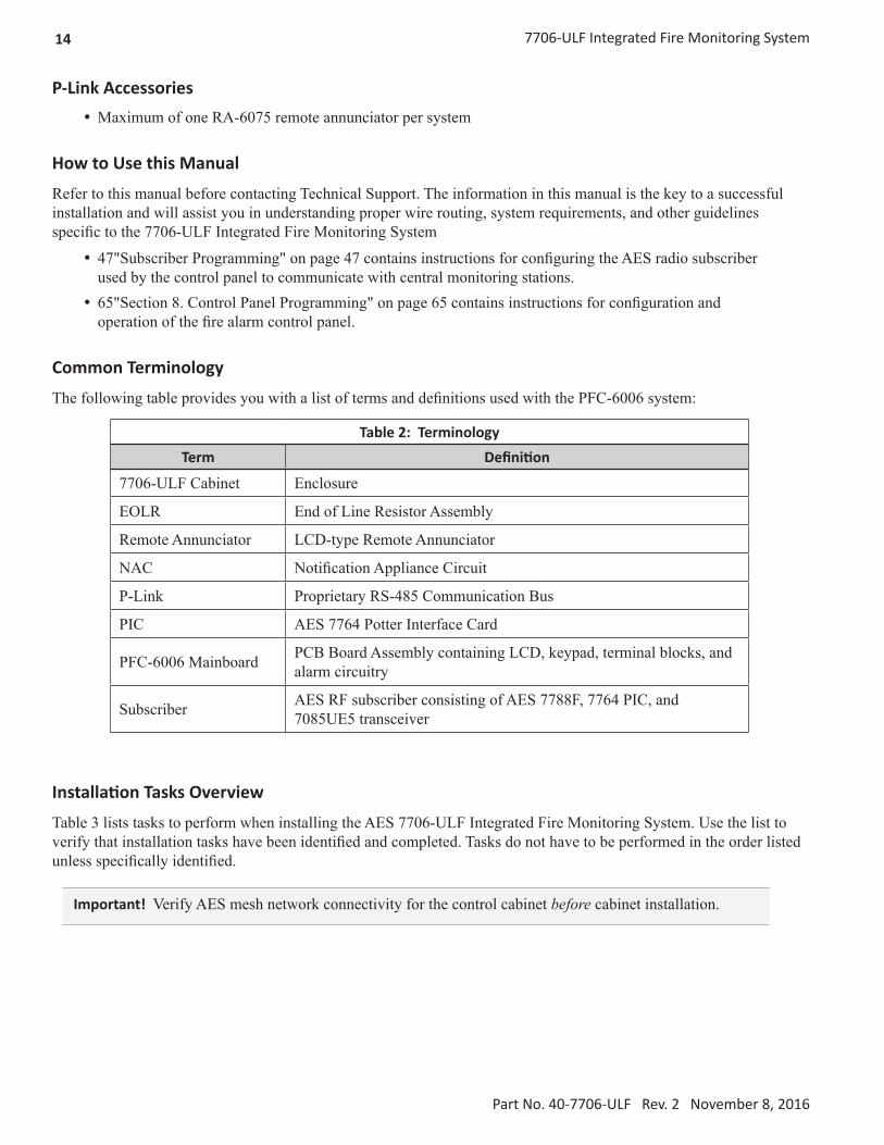
Before selecting the battery, it is important to determine the minimum size batteries for standby and alarm times desired for each application. If the wrong batteries are installed in a specific application or incorrect current draw is used, the proper standby and minimum alarm time will not be present.
The battery circuit is rated for 8 to 18 Ah batteries and will operate the panel alarm for at least 24 hours and 5 minutes. The cabinet will house up to two 14 Ah batteries. Larger size batteries must be placed in an NFPA 72 compliant external battery box.
Please use the worksheet shown below to calculate the battery size and current draw required for each application:
Battery Calculation Worksheet
Description QuantityStandby
(mA)
TotalStandby
(mA)Alarm(mA)
TotalAlarm (mA)
Mainboard (PFC-6006) 1 105 105 160 105
Subscriber (7788F, 7764, and 7085UE5) 1 200 200 200 200
LCD Remote RA-6075 1 20 25
Input Circuit #1
Input Circuit #2
Input Circuit #3
Input Circuit #4
Input Circuit #5
Input Circuit #6
NAC 1Total (mA) Total (mA)
Convert to Amps × 0.001 Convert to Amps × 0.001(*Refer to maximum allowable standby current) Total A: Total A:
Multiply by standby hours × ____
60 minutes per hour
Alarm time (minutes)
Example:
5 minute alarm: enter 12
÷ ____
Total Standby Ah Total Alarm Ah+Total Standby Ah
Total AhEfficiency Factor ÷ 0.85
Required Ah
*Maximum Allowable Standby Current
(UL 24-Hour standby time)
7 Ah .244 A
12 Ah .421 A
18 Ah .634 A
Important Notes:
1. FACP enclosure can house up to two 14 Ah batteries.
2. NFPA-72 requires 24 hours of standby power followed by 5 minutes of alarm activation.
3. LED/Relay current must be accounted for in the battery calculation for the supplying source.
4. Total current must not exceed power supply rating of 2A.

32 7706-ULF Integrated Fire Monitoring System
Part No. 40-7706-ULF Rev. 2 November 8, 2016
Main Supply Circuit
The AC terminals are located in the upper left-hand portion of the mainboard. The mainboard supervises the main AC power and provides indication that the AC power is absent. The terminals are rated at 120 VAC 60 Hz and are marked accordingly on the board.
L N
AC120V/AC230V,50/60HzAC POWER
BlackWhiteGround
120VAC 60 HzConnect to separateUnswitched AC circuit
Use 14 AWg wire or Heavier with 600V Insulation
DWG #559-10-7706
Figure 16. 7706-ULF AC Terminals
The earth ground connection is marked as “ " and is the furthest connection from the line voltage connection.
The AC input power rating is a maximum of 0.75A at the nominal 120 VAC rating.
Battery Connections
The battery charging circuit is located on the main panel in the lower left portion of the board. The maximum battery charging current is 0.5A DC; the charging voltage is approximately 27.3 VDC and is supervised.
Note: The battery should be clearly labeled as “Sealed Lead Acid Battery” or equivalent UL listed or UL recognized.

337706-ULF Integrated Fire Monitoring System
Part No. 40-7706-ULF Rev. 2 November 8, 2016
Connect the battery wire leads to the terminal connections, as shown in Figure 17 below. Batteries should be replaced every 5 years or sooner depending on annual testing.
PanelConnections
BATTERY- +
12 V Battery
- +12 V
Battery
- +
DWG # 593-5-7706-ULF-1
Figure 17. 7706-ULF Battery Connections
Section 5. Control Panel Installation
This section addresses installation procedures for Input Circuits 1–6, the NAC, and the optional RA-6075 remote annunciator. Wiring requirements and configuration examples are included throughout this section. Please read this section carefully before installing points and accessories to ensure proper installation.
Input Circuits
There are six programmable Input or Initiating Device Circuits (IDC) provided on the PFC-6006, which are the same as an integrated fire system input. They are supervised and power-limited to protect two-wire smoke detectors. Input Circuit #1 may be wired for either Class A, Style D or Class B, Style B, whereas Inputs #2-6 may be Class B, Style B only. All inputs are suitable for automatic, manual, waterflow or sprinkler supervisory service (refer to Figure 20 on page 37).
Note: The panel has the intelligence to determine the applicable style for Input Circuit #1 based on the wiring configuration used.
Input Wiring Specifications
y Maximum short circuit current = 32 mA. y Maximum wiring resistance = 100 ohms. y Maximum wiring capacitance = 1 mF. y Maximum wire length in feet = 100/ohms per 1 foot of wire. y Normal standby current = 2.5 mA. y Operating voltage range = 15.1– 25.4 VDC.

34 7706-ULF Integrated Fire Monitoring System
Part No. 40-7706-ULF Rev. 2 November 8, 2016
Input Circuit #1 Class A, Style D Wiring Configuration
L N G
BATTERY- +
NAC - +
AUX+-
P-LINK+- BA
ETHERNET INPUT 1A- A+ B- -B+ -+ -+ -+ -+ +
INPUT 2 INPUT 3 INPUT 4 INPUT 5 INPUT 6
TIP RING TIP RING TIP RING TIP RING
LINE 2 OUTLINE 2 IN LINE 1 OUTLINE 1 IN
WATERFLOW SWITCHNORMALLY OPEN CONTACTS
CLASS A WIRING
DWG #559-4
Figure 18. Example of Input 1, Class A, Style D
Notes: y Input Circuit #1 may be wired as either Class A or Class B. y All other inputs are Class B only. y Maximum wiring resistance must not exceed 100 ohms. y The input has ground fault detection with 0-ohm impedance to ground. y The EOL resistor assembly is a listed 5.1k ohm resistor.
357706-ULF Integrated Fire Monitoring System
Part No. 40-7706-ULF Rev. 2 November 8, 2016
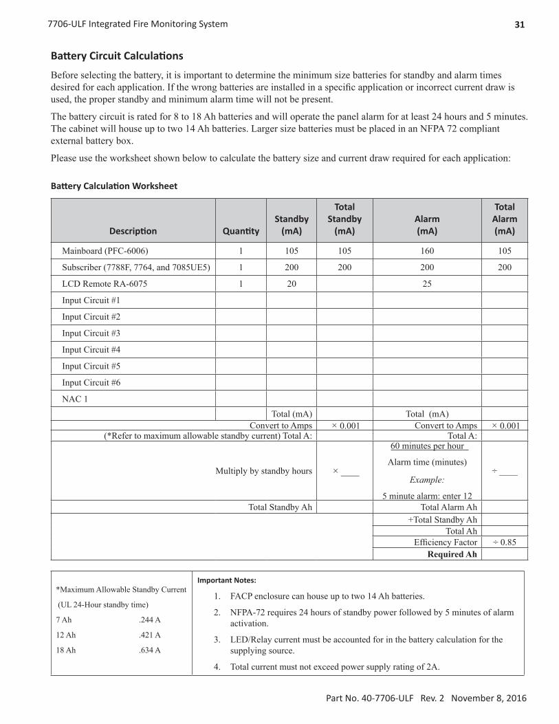
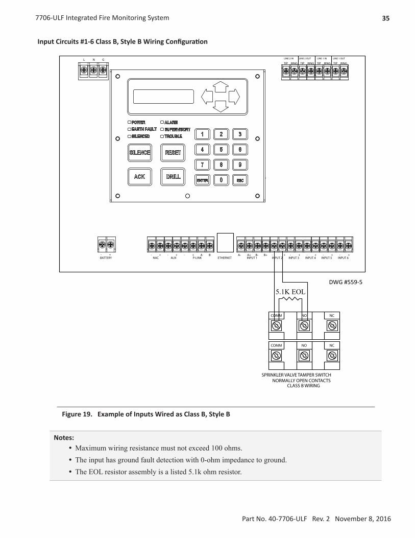
Input Circuits #1-6 Class B, Style B Wiring Configuration
L N G
BATTERY- +
NAC - +
AUX+-
P-LINK+- BA
ETHERNET INPUT 1A- A+ B- -B+ -+ -+ -+ -+ +
INPUT 2 INPUT 3 INPUT 4 INPUT 5 INPUT 6
TIP RING TIP RING TIP RING TIP RING
LINE 2 OUTLINE 2 IN LINE 1 OUTLINE 1 IN
COMM NO NC
COMM NO NC
5.1K EOL
SPRINKLER VALVE TAMPER SWITCHNORMALLY OPEN CONTACTS
CLASS B WIRING
DWG #559-5
Figure 19. Example of Inputs Wired as Class B, Style B
Notes: y Maximum wiring resistance must not exceed 100 ohms. y The input has ground fault detection with 0-ohm impedance to ground. y The EOL resistor assembly is a listed 5.1k ohm resistor.

36 7706-ULF Integrated Fire Monitoring System
Part No. 40-7706-ULF Rev. 2 November 8, 2016
Notification Appliance Circuits Installation
There is one NAC circuit provided on the PFC-6006 rated as continuous 0.5A at 24 VDC. The NAC circuit is configurable as Class B, Style Y only. (Please refer to the wiring example located in this section.)
NAC Wiring Characteristics
y Output is supervised and regulated. y Circuit is power limited. y Normal standby supervisory current is approximately 1.2 mA y Low current trouble activation is 0.8 mA; high current trouble activation is 1.7 mA. y Maximum RMS current is 0.5A.
Note: Type of NAC output is selectable, and may be configured for strobe synchronization with Potter/AMSECO®, Cooper Wheelock®, Gentex®, or System Sensor® strobe points. Refer to the listing of compatible models located in 128"Appendix H. PFC-6006 NAC Compatibility List" on page 128.

377706-ULF Integrated Fire Monitoring System
Part No. 40-7706-ULF Rev. 2 November 8, 2016
NAC Maximum Wiring Impedance Formula
The maximum impedance is a function of the load placed on the circuit. To calculate the maximum line current impedance, use the following formula:
(Alarm Current of Notification Appliance) x (Wire Resistance) < 1.2 Volts
NAC Wiring Configuration
NAC - +
NotificationAppliances
5.1k EOL
Potter Part # 3005013
Note: The resistance of external wiring shall be determinedusing the following formula:
(Alarm Current of Notification Appliance) x (Wire Resistance) < 1.2 Volts
DWG #559-6A
Figure 20. NAC Class B, Style Y Wiring Example
Notes: y The EOL resistor assembly is a listed 5.1k ohm resistor. y The panel has ground fault detection on the NAC circuit. The impedance to ground for ground fault detection is 0 ohm.
y The 1.2 volts is based on the worst case loading at the remote end of the NAC circuit (lump sum method). The total drop of 1.2 volts should be measured from the terminals to the most remote device.

38 7706-ULF Integrated Fire Monitoring System
Part No. 40-7706-ULF Rev. 2 November 8, 2016
P-Link Points
Accessory points, such as the RA-6075 remote annunciator, are connected to the main control panel utilizing the four-wire P-Link bus for power and communication. This panel supports a single P-Link point, which can be connected using a Class B, Style 4 wiring style.
Configuration Characteristics
y P-Link current rating may not exceed 0.5A based on the total between auxiliary and P-Link. y P-Link maximum current is 500 mA. y P-Link voltage rating is 24 VDC. y Continuous DC frequency. y P-Link circuit is supervised and power-limited.
Maximum Wire Resistance Formula (Wire Length)
The maximum resistance is based on the load placed on the circuit. To calculate the maximum wire resistance, use the following formula: (Total Annunciator Alarm Current) x (Wire Resistance) < 6 Volts
7764 PIC
RA-6075Remote Annunciator
-+
A B
P Link- + A B
7706-ULF
- + A B
Panel Connection
Field wire size must be the same as factory wire size when connecting both wires to the same screw terminal.
Do not mix use of solid and stranded wire on the same screw terminal.
Place one wire on each side of the terminal screw head.
Figure 21. P-Link Device Class B Wiring Example

397706-ULF Integrated Fire Monitoring System
Part No. 40-7706-ULF Rev. 2 November 8, 2016
P-Link Addresses
Every P-Link device has a five-position DIP switch which is used to program the device address. The addresses range from 1–31. See the chart below to reference DIP switch settings:
Annunciator Address
DIP Switch Settings Annunciator Address
DIP Switch Settings
SW-1 SW-2 SW-3 SW-4 SW-5 SW-1 SW-2 SW-3 SW-4 SW-5
1 On Off Off Off Off 17 On Off Off Off On2 Off On Off Off Off 18 Off On Off Off On3 On On Off Off Off 19 On On Off Off On4 Off Off On Off Off 20 Off Off On Off On5 On Off On Off Off 21 On Off On Off On6 Off On On Off Off 22 Off On On Off On7 On On On Off Off 23 On On On Off On8 Off Off Off On Off 24 Off Off Off On On9 On Off Off On Off 25 On Off Off On On10 Off On Off On Off 26 Off On Off On On11 On On Off On Off 27 On On Off On On12 Off Off On On Off 28 Off Off On On On13 On Off On On Off 29 On Off On On On14 Off On On On Off 30 Off On On On On15 On On On On Off 31 On On On On On16 Off Off Off Off On
Remote Annunciators Installation (RA-6075)
One annunciator may be connected to the main sprinkler monitoring panel. The RA-6075 provides a 2 × 16 character LCD display, along with standard function and numeric keys. It is listed and designed to be mounted on a flat noncondensing surface or electrical box.
Setting Addresses
The annunciator's address is set by DIP switch S1, which is located on the back of the annunciator. The address must be set in the range of 1–31 to be recognized by the panel.
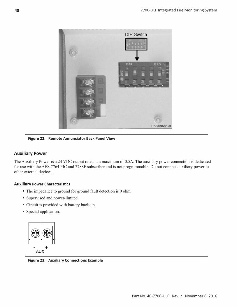
40 7706-ULF Integrated Fire Monitoring System
Part No. 40-7706-ULF Rev. 2 November 8, 2016
Figure 22. Remote Annunciator Back Panel View
Auxiliary Power
The Auxiliary Power is a 24 VDC output rated at a maximum of 0.5A. The auxiliary power connection is dedicated for use with the AES 7764 PIC and 7788F subscriber and is not programmable. Do not connect auxiliary power to other external devices.
Auxiliary Power Characteristics
y The impedance to ground for ground fault detection is 0 ohm. y Supervised and power-limited. y Circuit is provided with battery back-up. y Special application.
AUX- +
Figure 23. Auxiliary Connections Example

417706-ULF Integrated Fire Monitoring System
Part No. 40-7706-ULF Rev. 2 November 8, 2016
DACT Connection
NOTICEPhone lines are high voltage and should be run in a separate conduit from other circuits. The wire conductors connecting the DACT to the phone system should be 26 AWG or larger.
The Digital Alarm Communicator Transmitter (DACT) provides connections for two phone lines for communication to a monitoring station. The DACT communicates using the SIA-DCS or Ademco Contact ID protocols. The DACT is selectable and fully programmable.
The PFC-6006 automatically monitors each phone line for voltage and has the ability to seize the line and connect with a remote receiver. Once the communication is complete, the DACT will hang up the phone line.
The DACT is provided with a terminal block for each phone line, as shown in the figure below. In order for the DACT to work properly, it must be installed on a plain old telephone service (POTS) or equivalent as deemed by the authority having jurisdiction. The DACT must be installed before any other equipment to ensure it can seize the line and disconnect any other lines.
TIP RING TIP RING TIP RING TIP RING
LINE 2 OUTLINE 2 IN LINE 1 OUTLINE 1 IN
When the phone lines are connected to the control panel, the phone lines are supervised. The phone lines are non-power limited and should be routed accordingly.
In order for the system to comply with building and fire codes, the DACT is to be connected between the telephone company connection and other appliances serving the building. Failure of the DACT to be the first device on the line will prevent it from seizing the phone line and acquiring dial tone.
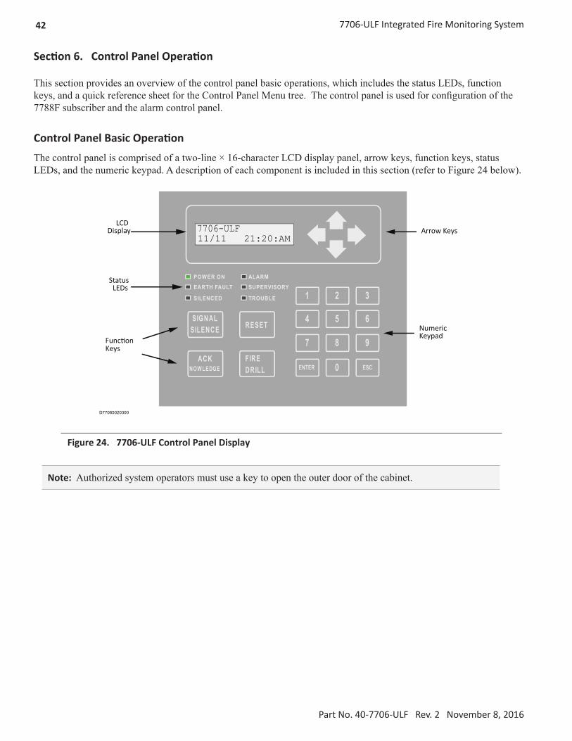
42 7706-ULF Integrated Fire Monitoring System
Part No. 40-7706-ULF Rev. 2 November 8, 2016
Section 6. Control Panel Operation
This section provides an overview of the control panel basic operations, which includes the status LEDs, function keys, and a quick reference sheet for the Control Panel Menu tree. The control panel is used for configuration of the 7788F subscriber and the alarm control panel.
Control Panel Basic Operation
The control panel is comprised of a two-line × 16-character LCD display panel, arrow keys, function keys, status LEDs, and the numeric keypad. A description of each component is included in this section (refer to Figure 24 below).
SIGNALSILENCE
POWER ON
EARTH FAULT
SILENCED
ALARM
SUPERVISORY
TROUBLE
RESET
ACK EG DELWON
FIREDRILL
1 2 3
4 5 6
7 8 9
0 ESCENTER
LCDDisplay
StatusLEDs
Function Keys
Arrow Keys
NumericKeypad
7706-ULF11/11 21:20:AM
D77065020300
Figure 24. 7706-ULF Control Panel Display
Note: Authorized system operators must use a key to open the outer door of the cabinet.

437706-ULF Integrated Fire Monitoring System
Part No. 40-7706-ULF Rev. 2 November 8, 2016
LCD Display
The LCD panel displays the standard Start-up menu as shown in Figure 25 below. The LCD displays up to 32 characters of information displays, providing important feedback to system users, i.e., system messages, status information, trouble conditions, or input changes. The LCD also provides access to the Main Menu for daily system operations and specific programming functions (refer to 42"Section 6. Control Panel Operation" on page 42 for details on these topics).
7706-ULF11/11 21:20:00PM
D77065020401
Figure 25. LCD Start-Up Screen
Note: You may customize the Start-up screen to display a specific job site name or other relevant descriptive text.
Menu Navigation Keys
The arrow keys allow you to scroll or move through the control panel menus. The Enter and Esc keys may also be used to navigate through menus; they are located on the numeric keypad. Table 10 provides a summary of the navigation keys.
Table 10: Menu Navigation Keys
Keys Description
Moves/scrolls up or down through menus.
Scrolls to the left or right to display details, if any, of current menu item.
Note: When the LCD panel displays a left and/or right arrow, this indicates more information may be viewed.
Displays the Main Menu or selects the current menu option.
Note: The blinking “” indicates the current menu option.
Returns to previous menu or backs up to previous screen.

44 7706-ULF Integrated Fire Monitoring System
Part No. 40-7706-ULF Rev. 2 November 8, 2016
Numeric Keypad
The numeric keypad allows you to enter user codes when required to access restricted functions. Alternatively, the numbers may be used to quickly select menu options, rather than using the arrow and Enter keys to select a function.
Figure 26. Control Panel Numeric Keypad
Function Keys
The four function keys are used when system alarm/trouble conditions occur or to perform a fire drill. Refer to Table 11 below for a brief summary of the function keys:
Table 11: Control Panel Function Keys
Function Keys Description
Press to acknowledge the currently displayed condition.
Press to silence all outputs programmed as silenceable and buzzer.
Press to reset panel to normal condition.
Press to begin a fire drill.

457706-ULF Integrated Fire Monitoring System
Part No. 40-7706-ULF Rev. 2 November 8, 2016
Status LEDs
The control panel’s LEDs communicate system conditions by illuminating and/or flashing the applicable green, red, or amber indicators. These are described in the table below.
Figure 27. Control Panel Status LEDs
Table 12: Status LEDs
LED Type LED Color/Action Description
POWER ON Steady GreenPower is present.If power is absent for more than 5 seconds, LED will extinguish.
ALARM Flashing Red An alarm device is active.ALARM Steady Red An alarm device is acknowledged.EARTH FAULT Flashing Amber A ground fault is present.SUPERVISORY Flashing Amber A supervisory condition is present.SILENCED Steady Amber A fault condition has been silenced.TROUBLE Flashing Amber A fault condition is present.

46 7706-ULF Integrated Fire Monitoring System
Part No. 40-7706-ULF Rev. 2 November 8, 2016
Control Panel Menu Tree
Figure 28 displays the menu options as they appear on the LCD panel (see also Appendix G for the menu tree).
Main Menu
1=View History 2=Enable/Disable 3=Set Date/Time 4=Walk Test 5=System Tools 6=Programming 7=Data Transfer Esc=Exit
1=By Point 2=By Zone
Select DeviceInternal PWR
1=Point Control2=Ethernet Status3=DACT Test4=DACT Reset5=Erase History6=Lamp Test7=App Revisions8=PIC StatusEsc=Exit
Zone _ _ _ _(Enter Zone #and press Enter)
1=Disable Inputs2=Disable OptionsEsc=Exit
Select Data1=Remote Access2=Email History3=Email Config4=Email Test5=Server StatusEsc=Exit
6=Programming
1=AC PWR Delay2=DACT Setup3=Display ModeEsc=Exit
System Setup1=Line 1 Setup2=Line 2 Setup3=Acct 1 Setup4=Acct 2 Setup5=Acct 3 Setup6=Acct 4 Setup7=Acct 5 SetupEsc=Exit
DACT Setup1=Enable/Disable2=Line Monitor3=No. of Rings4=Ans. Machine5=Line Prefix6=Dial Tone Det.Esc=Exit
Line Setup
1=Report Event Type2=Pri Acct ID3=Pri Phone No.4=Pri Rpt. Test6=Sec Acct. ID7=Sec Phone No.8=Sec Rpt. Fmt.9=Sec. Rpt. TestEsc=Exit
Account Setup
1=USA2=CanadaEsc=Exit
Display Mode
1=DHCP Settings2=Default IP3=Default Gatewy4=Default Settings5=Alternate IP6=Alt. Gateway7=Alt. SubnetEsc=Exit
IP Settings
1=Username2=PasswordEsc=Exit
Def. ID/Passwd
1=System Setup2=LEARN Mode3=Panel Default4=IP Settings5=Def. ID/Passwd6=Prog ID/Passwd7=PIC Config.Esc=Exit
7=PIC Config.
1=System Setup2=LEARN Mode3=Panel Default4=IP Settings5=Def. ID/Passwd6=Prog ID/Passwd7=PIC Config.Esc=Exit
1=Setup2=Timers3=Modes4=Time to Live5=Acct Override6=User Codes7=Report Acct.8=Default PICEsc=Exit
7=PIC Config.
PIC Config.
1=PIC Status2=Route TableEsc=Exit
PIC Menu
8=PIC Status7=PIC Config.
Figure 28. Control Panel Menu Tree

477706-ULF Integrated Fire Monitoring System
Part No. 40-7706-ULF Rev. 2 November 8, 2016
Section 7. Subscriber Specifications
Features
This section is included for those customers familiar with other AES-IntelliNet UL Subscriber products. Listed below are the new features utilized with the unit as part of the 7706-ULF System.
y Fail Secure Relay on board relay function is monitored through the 7764 PIC card. Connection to the relay is not required. The status of the 7788F is monitored by the PFC-6006 mainboard.
y Transceiver power PTC is added. It is installed in series with the power line to the transceiver disconnecting power if the transceiver draws too much current.
y Remote AES 7788F subscriber programming using software at the central station is disabled .This is to comply with UL/NFPA requirements.
Optional Accessories
No optional accessories are available with the 7788F used in the 7706-ULF Integrated Fire Monitoring System.
Subscriber Technical Specifications y Voltage: 12 VDC nominal; power supplied from the PCF-6006 mainboard y Current: 150 mA standby; 1.2A transmit y RESET button: Located on the PCB y Transceiver: Standard UHF Frequency Ranges (410-440 MHz, 440-470 MHz, 470-512 MHz) y Transceiver Fuse: 400 milliamp PTC, not serviceable y Standard RF Output Power: 2 Watts y Antenna Cut/Low Battery/Charger Fail Local Reporting: Controlled by the PFC-6006 mainboard
Subscriber Local Trouble Output y The control panel monitors the 7788F Trouble condition. y Do not connect to the J4 Trouble Output relay terminals.
Subscriber Programming
This section describes the configuration required for a subscriber to join the AES mesh network. Initial subscriber configuration must be performed on factory new units for the subscriber to join and communicate on the network properly.
The subscriber is programmed through the AES 7764 PIC card. The keypad on the control panel display allows navigation of the LCD panel menu options (see 46"Figure 28. Control Panel Menu Tree" on page 46) and the ability to examine and change settings for the 7788F subscriber. Previously programmed information is stored in non-volatile memory, so the settings are not lost during power-down of the 7706-ULF or power failure.
Important! The following 7788F subscriber features are not available in the 7706-ULF System.
y Remote Programming (disabled to comply with UL/NFPA requirements) y Monitor Transmitter

48 7706-ULF Integrated Fire Monitoring System
Part No. 40-7706-ULF Rev. 2 November 8, 2016
y Key Transmitter y Display Zone Status y Text Messages y AC Fail, Charger Fault, Ground Fault: Not configurable on the 7788F when used in the 7706-ULF Integrated Fire Monitoring System. AC fail functionality is handled by the mainboard.
y Zone Programming: Zone programming is fixed and cannot be changed for the 7788F when used as part of the 7706-ULF System.
1. Turn on the AC power to the system.
2. Connect the standby batteries with the cable provided to perform programming.
Important! Battery polarity must be observed.
Notes:
y The panel will perform initialization and self-test after power is applied. A series of messages appear in the display.
y The error message Trb-AES Comm in the display means the mainboard is unable to communicate with the 7788F subscriber (see "Appendix G. Verifying 7764 PIC Operation and Troubleshooting Steps").

497706-ULF Integrated Fire Monitoring System
Part No. 40-7706-ULF Rev. 2 November 8, 2016
ID # and System Cipher Code
This function programs the unit ID# and the AES system cipher code. Access to view or change is available locally through the mainboard keypad or through the optional Potter Remote Annunciator.
Menu location: Programming > PIC Config > PIC Options > 1=Setup
6=Programming
ID#Cphr Code
1=System Setup2=LEARN Mode3=Panel Default4=IP Settings5=Def. ID/Passwd6=Prog ID/Passwd7=PIC Config.Esc=Exit
1=Setup2=Timers3=Modes4=Time to Live5=Acct Override6=User Codes7=Report Acct.8=Default PICEsc=Exit
7=PIC Config.PIC Options
Notes: y It is not possible to remotely program the unit ID# or system cipher code through the AES radio network.
y The unit ID# must be unique and different from all other ID#'s in your network. y Entering new data overwrites (erases) any previously stored ID number and system cipher code.
1. From the control panel, press ENTER to display the Main Menu.
2. Press 6, then ENTER, to access the Programming menu. The Enter Code prompt displays.
3. Enter the user access code.
4. At the Programming menu:
y Press 7 to select PIC Config. y From the PIC Options menu, press 1 to select Setup.
The ID# prompt displays the current ID number. The subscriber ID# is four hexadecimal characters.

50 7706-ULF Integrated Fire Monitoring System
Part No. 40-7706-ULF Rev. 2 November 8, 2016
5. To change the existing ID#, press the characters of the subscriber ID# on the keypad.
Note: To enter characters A–F, first press the up-arrow key. Then press the keypad number that corresponds to the hexadecimal character as shown in Figure 29.
1|A
2|B
3|C
4|
D
5|E
6|F
Keypad Number
Hex Character
Figure 29. Keypad Number to Hexadecimal Character Chart
Example: To enter the ID# ABCD:
1. Press the up-arrow key once on the keypad. The word Shift appears in the LCD.
2. Press 1. The letter A appears in the ID#.
3. Continue by pressing the up-arrow key and then 2 for B.
4. Repeat the up-arrow and number key combination for the remaining characters until the full ID# has been entered.
6. Press ENTER after entering the ID#. The Cphr Code prompt displays with the current cipher code.
Note: The actual characters of the current cipher code are not shown for security. Instead, four asterisks (****) are displayed.
7. Enter the 4-character hexadecimal cipher code as assigned by the system administrator. The cipher code must match the system cipher code. Only a correct cipher code will allow the subscriber to log on to the network to communicate.
Note: To enter characters A–F, first press the up-arrow key. Then press the keypad number that corresponds to the hexadecimal character as shown in Figure 29.
8. Press ENTER after entering the cipher code. The PIC Options display appears. ID# and cipher code programming is complete.

517706-ULF Integrated Fire Monitoring System
Part No. 40-7706-ULF Rev. 2 November 8, 2016
Timing Parameters
This programming function is used to set timing parameters of Checkin Time, NTR RPT DLY, and Comm Timeout for the 7788F.
Menu Location: Programming > PIC Config > PIC Options > 2=Timers
6=Programming
Checkin TimeNTR RPT DLYComm Timeout
1=System Setup2=LEARN Mode3=Panel Default4=IP Settings5=Def. ID/Passwd6=Prog ID/Passwd7=PIC Config.Esc=Exit
1=Setup2=Timers3=Modes4=Time to Live5=Acct Override6=User Codes7=Report Acct.8=Default PICEsc=Exit
7=PIC Config.PIC Options
1. From the control panel, press ENTER to display the Main Menu.
2. Press 6, then ENTER, to access the Programming menu. The Enter Code prompt displays.
3. Enter the user access code.
4. At the Programming menu, press 7 to select PIC Config.
5. At the PIC Options menu, press 2 to select Timers. The Checkin Time prompt displays with the subscriber check in time value.
Note: Checkin Time default is 23:45 (23 hours and 45 minutes). This is also a recommended setting.
Important! Short intervals between check-in times are a cause of more traffic on the radio network. Carefully consider the effect before implementing a short interval.
6. Enter the number of hours using the numeric keypad, or press ENTER to skip and go to the next parameter. Valid entries are between 00–24 hours.
7. Press the right-arrow key to move the cursor to the minute position.
8. Enter the number of minutes using the numeric keypad. 00 hours, 00 minutes is an illegal entry and will not be accepted.
9. Press ENTER after entering the Checkin Time value. The NTR RPT DLY prompt displays.
The Reporting Delay sets the rate at which a subscriber’s own signals are transmitted. The initial alarm is sent immediately regardless of setting. Subsequent alarms are sent as specified by the delay setting. The

52 7706-ULF Integrated Fire Monitoring System
Part No. 40-7706-ULF Rev. 2 November 8, 2016
default value and recommended setting is 10 seconds; transmissions are sent at least 10 seconds apart (this helps to meter traffic on the system). The range is 0–80 seconds (no delay, not recommended).
For all commercial fire alarms, the reporting interval must not exceed 20 seconds. After the reporting delay has expired, a new event will not have any delay, and the attempt to send a new message will begin immediately after activation.
10. Enter the number of seconds using the numeric keypad, or press ENTER to skip and go to the next parameter. Default Reporting Delay is 10 seconds.
11. Press ENTER after entering the delay value. The Comm Timeout prompt displays.
12. Enter the number of seconds using the numeric keypad, or press ENTER to skip. Valid entries are between 1–80 seconds.
Modes
Menu Location: Programming > PIC Config > PIC Options > 3=Modes
6=Programming
Enable Repeating
1=System Setup2=LEARN Mode3=Panel Default4=IP Settings5=Def. ID/Passwd6=Prog ID/Passwd7=PIC Config.Esc=Exit
1=Setup2=Timers3=Modes4=Time to Live5=Acct Override6=User Codes7=Report Acct.8=Default PICEsc=Exit
7=PIC Config.PIC Options
1. From the control panel, press ENTER to display the Main Menu.
2. Press 6, then ENTER, to access the Programming menu. The Enter Code prompt displays.
3. Enter the user access code.
4. At the Programming menu, press 7 to select PIC Config.
5. At the PIC Options menu, press 3 to select Modes. The Enable Repeating prompt displays.
6. To accept the default value of Yes, press ENTER. To change the value to No, press the left-arrow or right-arrow key, then press ENTER.
7. The 3=Mode prompt displays. Select the next parameter item to configure, or press ESC to exit the PIC Options menu.
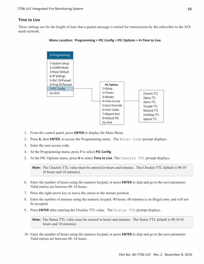
537706-ULF Integrated Fire Monitoring System
Part No. 40-7706-ULF Rev. 2 November 8, 2016
Time to Live
These settings are for the length of time that a packet message is retried for transmission by the subscriber to the AES mesh network.
Menu Location: Programming > PIC Config > PIC Options > 4=Time to Live
6=Programming
Checkin TTLStatus TTLAlarm TTLTrouble TTLRestoral TTLIntellitap TTLSpecial TTL
1=System Setup2=LEARN Mode3=Panel Default4=IP Settings5=Def. ID/Passwd6=Prog ID/Passwd7=PIC Config.Esc=Exit
1=Setup2=Timers3=Modes4=Time to Live5=Acct Override6=User Codes7=Report Acct.8=Default PICEsc=Exit
7=PIC Config.PIC Options
1. From the control panel, press ENTER to display the Main Menu.
2. Press 6, then ENTER, to access the Programming menu. The Enter Code prompt displays.
3. Enter the user access code.
4. At the Programming menu, press 7 to select PIC Config.
5. At the PIC Options menu, press 4 to select Time to Live. The Checkin TTL prompt displays.
Note: The Checkin TTL value must be entered in hours and minutes. The Checkin TTL default is 00:10 (0 hours and 10 minutes).
6. Enter the number of hours using the numeric keypad, or press ENTER to skip and go to the next parameter. Valid entries are between 00–24 hours.
7. Press the right-arrow key to move the cursor to the minute position.
8. Enter the number of minutes using the numeric keypad. 00 hours, 00 minutes is an illegal entry and will not be accepted.
9. Press ENTER after entering the Checkin TTL value. The Status TTL prompt displays.
Note: The Status TTL value must be entered in hours and minutes. The Status TTL default is 00:10 (0 hours and 10 minutes).
10. Enter the number of hours using the numeric keypad, or press ENTER to skip and go to the next parameter. Valid entries are between 00–24 hours.

54 7706-ULF Integrated Fire Monitoring System
Part No. 40-7706-ULF Rev. 2 November 8, 2016
11. Press the right-arrow key to move cursor to the minute position.
12. Enter the number of minutes using the numeric keypad. 00 hours, 00 minutes is an illegal entry and will not be accepted.
13. Press ENTER after entering the Status TTL value. The Alarm TTL prompt displays.
Note: The Alarm TTL value must be entered in hours and minutes. The Alarm TTL default is 03:00 (3 hours and 0 minutes)
14. Enter the number of hours using the numeric keypad, or press ENTER to skip and go to the next parameter. Valid entries are between 00–24 hours.
15. Press the right-arrow key to move the cursor to the minute position.
16. Enter the number of minutes using the numeric keypad. 00 hours and 00 minutes is an illegal entry and will not be accepted.
17. Press ENTER after entering the Alarm TTL value. The Trouble TTL prompt displays.
Note: The Trouble TTL value must be entered in hours and minutes. The Trouble TTL default is 03:00 (3 hours and 0 minutes).
18. Enter the number of hours using the numeric keypad, or press ENTER to skip and go to the next parameter. Valid entries are between 00–24 hours.
19. Press the right-arrow key to move the cursor to the minute position.
20. Enter the number of minutes using the numeric keypad. 00 hours, 00 minutes is an illegal entry and will not be accepted.
21. Press ENTER after entering the Trouble TTL value. The Restoral TTL prompt displays.
Note: The Restoral TTL value must be entered in hours and minutes. The Restoral TTL default is 03:00 (3 hours and 0 minutes).
22. Enter the number of hours using the numeric keypad, or press ENTER to skip and go to the next parameter. Valid entries are between 00–24 hours.
23. Press the right-arrow key to move the cursor to the minute position.
24. Enter the number of minutes using the numeric keypad. 00 hours, 00 minutes is an illegal entry and will not be accepted.
25. Press ENTER after entering the Restoral TTL value. The IntelliTap TTL prompt displays.
Note: The IntelliTap value must be entered in hours and minutes. The IntelliTap default is 00:10 (0 hours and 10 minutes)
26. Enter the number of hours using the numeric keypad, or press ENTER to skip and go to the next parameter. Valid entries are between 00–24 hours.
27. Press the right-arrow key to move the cursor to the minute position.
28. Enter the number of minutes using the numeric keypad. 00 hours, 00 minutes is an illegal entry and will not be accepted.

557706-ULF Integrated Fire Monitoring System
Part No. 40-7706-ULF Rev. 2 November 8, 2016
29. Press ENTER to go to the next parameter. The Special TTL prompt displays.
Note: The Special TTL value is not used in this application.
30. Press ENTER. The 4=Time to Live prompt displays. Press ESC to exit the PIC Options menu.
Account Override
The Account Override option allows use of the subscriber ID# in place of the FACP identification number.
Menu Location: Programming > PIC Config > PIC Options > 5=Acct Override
6=Programming
Acct Override
1=System Setup2=LEARN Mode3=Panel Default4=IP Settings5=Def. ID/Passwd6=Prog ID/Passwd7=PIC Config.Esc=Exit
1=Setup2=Timers3=Modes4=Time to Live5=Acct Override6=User Codes7=Report Acct.8=Default PICEsc=Exit
7=PIC Config.PIC Options
1. From the control panel, press ENTER to display the Main Menu.
2. Press 6, then ENTER, to access the Programming menu. The Enter Code prompt displays.
3. Enter the user access code.
4. At the Programming menu, press 7 to select PIC Config. The PIC Options prompt displays.
5. Press 5 to select Acct Override. The Acct Override prompt displays.
Note: Acct Override default setting is No.
6. Press the up-arrow key to change the value, or press ENTER to skip and go to the next parameter. Press ESC to exit the PIC Options menu.

56 7706-ULF Integrated Fire Monitoring System
Part No. 40-7706-ULF Rev. 2 November 8, 2016
User Codes
Menu Location: Programming > PIC Config > PIC Options > 6=User Codes
6=Programming
User Codes
1=System Setup2=LEARN Mode3=Panel Default4=IP Settings5=Def. ID/Passwd6=Prog ID/Passwd7=PIC Config.Esc=Exit
1=Setup2=Timers3=Modes4=Time to Live5=Acct Override6=User Codes7=Report Acct.8=Default PICEsc=Exit
7=PIC Config.PIC Options
1. From the control panel, press ENTER to display the Main Menu.
2. Press 6, then ENTER, to select Programming. The Enter Code prompt displays.
3. Enter the user access code.
4. At the Programming menu, press 7 to select PIC Config. The PIC Options prompt displays.
5. Press 6 to select User Codes. The User Codes prompt displays.
Note: User Codes default setting is No.
6. Press the up-arrow key to change the value, or press ENTER to skip and go to the next parameter.
7. Press ESC to exit this menu.

577706-ULF Integrated Fire Monitoring System
Part No. 40-7706-ULF Rev. 2 November 8, 2016
Report Account
Menu Location: Programming > PIC Config > PIC Options > 7=Report Acct
6=Programming
Rpt AlarmsRpt TroublesRpt SupervisoryRpt ByRpt Acct
1=System Setup2=LEARN Mode3=Panel Default4=IP Settings5=Def. ID/Passwd6=Prog ID/Passwd7=PIC Config.Esc=Exit
1=Setup2=Timers3=Modes4=Time to Live5=Acct Override6=User Codes7=Report Acct.8=Default PICEsc=Exit
7=PIC Config.PIC Options
1. From the control panel, press ENTER to display the Main Menu.
2. Press 6, then ENTER, to select Programming. The Enter Code prompt displays.
3. Enter the user access code.
4. At the Programming menu, press 7 to select PIC Config. The PIC Options prompt displays.
5. Press 7 to select Report Acct. The Rpt Alarms prompt displays.
Note: The default setting is Yes.
6. Press the up-arrow key to change the value, then press ENTER to go to the next parameter. The Rpt Troubles prompt displays.
Note: The default setting is Yes.
7. Press the up-arrow key to change the value, then press ENTER to go to the next parameter. The Rpt Supervisory prompt displays.
Note: The default setting is Yes.
8. Press the up-arrow key to change the value, then ESC to exit, or press ENTER to skip and go to the next parameter. The Rpt Test prompt displays.
Note: The default setting is Yes.

58 7706-ULF Integrated Fire Monitoring System
Part No. 40-7706-ULF Rev. 2 November 8, 2016
9. Press the up-arrow key to change the value, then ESC to exit, or press ENTER to skip and go to the next parameter. The Report By prompt displays.
Note: The default setting is Zone.
10. Press the up-arrow key to change the value, then ESC to exit, or press ENTER to skip and go to the next parameter. The Report Account prompt displays.
Note: The default setting is 1234.
11. Press the up-arrow key to change the value. The left/right arrow key allows movement between digits to set them. Press ESC to exit after entering values, or press ENTER to skip and go to the next parameter.
12. Press ENTER to return to the Report Acct menu.
Default PIC
Menu Location: Programming > PIC Config > PIC Options > 8=Default PIC
6=Programming
Default PIC
1=System Setup2=LEARN Mode3=Panel Default4=IP Settings5=Def. ID/Passwd6=Prog ID/Passwd7=PIC Config.Esc=Exit
1=Setup2=Timers3=Modes4=Time to Live5=Acct Override6=User Codes7=Report Acct.8=Default PICEsc=Exit
7=PIC Config.PIC Options
Important! This command functions the same as the 7788F Reset RAM function. It should be used only when a reset to factory settings of subscriber parameters is required. All existing parameters, except ID# and System Cipher Code, are reset back to factory default values.
1. From the control panel, press ENTER to display the Main Menu.
2. Press 6, then ENTER, to select Programming. The Enter Code prompt displays.
3. Enter the user access code.
4. At the Programming menu, press 7 to select PIC Config. The Default PIC prompt displays.
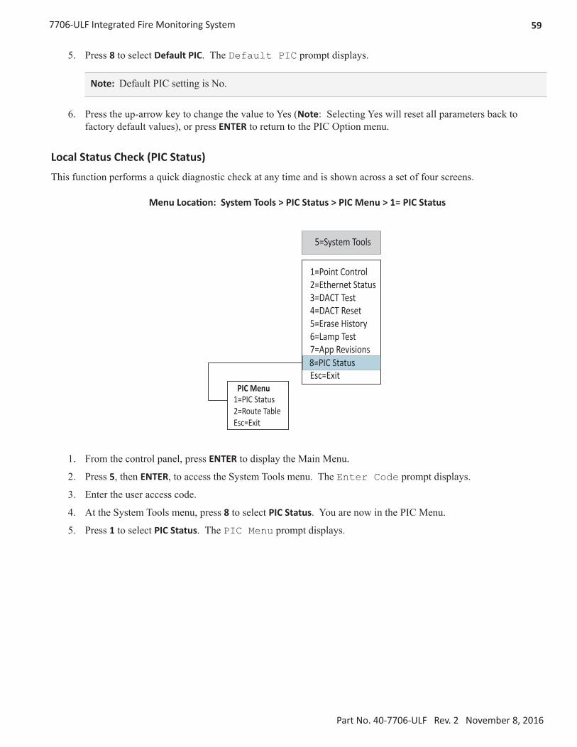
597706-ULF Integrated Fire Monitoring System
Part No. 40-7706-ULF Rev. 2 November 8, 2016
5. Press 8 to select Default PIC. The Default PIC prompt displays.
Note: Default PIC setting is No.
6. Press the up-arrow key to change the value to Yes (Note: Selecting Yes will reset all parameters back to factory default values), or press ENTER to return to the PIC Option menu.
Local Status Check (PIC Status)
This function performs a quick diagnostic check at any time and is shown across a set of four screens.
Menu Location: System Tools > PIC Status > PIC Menu > 1= PIC Status
5=System Tools
1=Point Control2=Ethernet Status3=DACT Test4=DACT Reset5=Erase History6=Lamp Test7=App Revisions8=PIC StatusEsc=Exit
1=PIC Status2=Route TableEsc=Exit
PIC Menu
8=PIC Status
1. From the control panel, press ENTER to display the Main Menu.
2. Press 5, then ENTER, to access the System Tools menu. The Enter Code prompt displays.
3. Enter the user access code.
4. At the System Tools menu, press 8 to select PIC Status. You are now in the PIC Menu.
5. Press 1 to select PIC Status. The PIC Menu prompt displays.
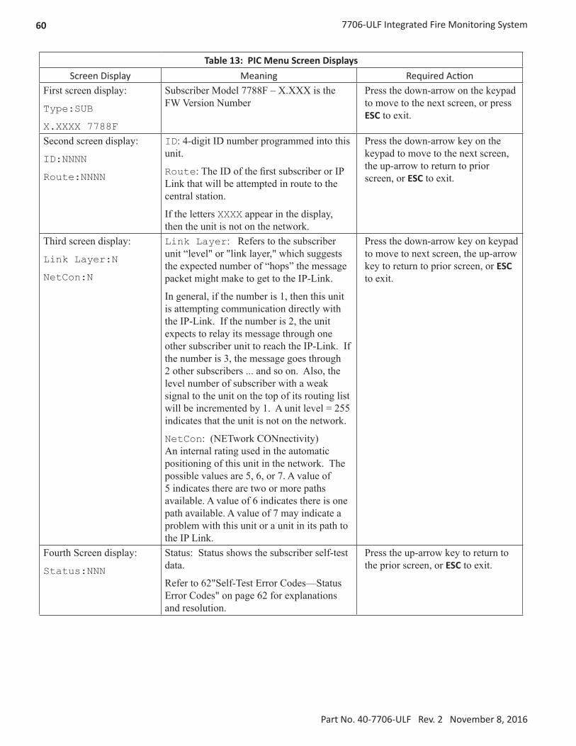
60 7706-ULF Integrated Fire Monitoring System
Part No. 40-7706-ULF Rev. 2 November 8, 2016
Table 13: PIC Menu Screen DisplaysScreen Display Meaning Required Action
First screen display:
Type:SUB
X.XXXX 7788F
Subscriber Model 7788F – X.XXX is the FW Version Number
Press the down-arrow on the keypad to move to the next screen, or press ESC to exit.
Second screen display:
ID:NNNN
Route:NNNN
ID: 4-digit ID number programmed into this unit.
Route: The ID of the first subscriber or IP Link that will be attempted in route to the central station.
If the letters XXXX appear in the display, then the unit is not on the network.
Press the down-arrow key on the keypad to move to the next screen, the up-arrow to return to prior screen, or ESC to exit.
Third screen display:
Link Layer:N
NetCon:N
Link Layer: Refers to the subscriber unit “level" or "link layer," which suggests the expected number of “hops” the message packet might make to get to the IP-Link.
In general, if the number is 1, then this unit is attempting communication directly with the IP-Link. If the number is 2, the unit expects to relay its message through one other subscriber unit to reach the IP-Link. If the number is 3, the message goes through 2 other subscribers ... and so on. Also, the level number of subscriber with a weak signal to the unit on the top of its routing list will be incremented by 1. A unit level = 255 indicates that the unit is not on the network.
NetCon: (NETwork CONnectivity) An internal rating used in the automatic positioning of this unit in the network. The possible values are 5, 6, or 7. A value of 5 indicates there are two or more paths available. A value of 6 indicates there is one path available. A value of 7 may indicate a problem with this unit or a unit in its path to the IP Link.
Press the down-arrow key on keypad to move to next screen, the up-arrow key to return to prior screen, or ESC to exit.
Fourth Screen display:
Status:NNN
Status: Status shows the subscriber self-test data.
Refer to 62"Self-Test Error Codes—Status Error Codes" on page 62 for explanations and resolution.
Press the up-arrow key to return to the prior screen, or ESC to exit.

617706-ULF Integrated Fire Monitoring System
Part No. 40-7706-ULF Rev. 2 November 8, 2016
Notes: All Fire Alarm installations require a NetCon value of 5. Minimum criteria for a "good" repeater are as follows:
1. The RF signal exceeds good threshold.
2. No faults are indicated in status (such as low battery).
3. Level/Link Layer of Subscriber/IP-Link is less than or equal to that of this unit.
4. The signal received from the Subscriber/IP-Link occurs at least once every 6 hours.
Display Route Table
Use this function to display the ID#’s listed in this Subscriber’s current Routing Table. Up to eight ID numbers may be available for display. A single ID in the Routing Table is displayed in the LCD display.
Menu Location: System Tools > PIC Status > PIC Menu > 2=Route Table
5=System Tools
1=Point Control2=Ethernet Status3=DACT Test4=DACT Reset5=Erase History6=Lamp Test7=App Revisions8=PIC StatusEsc=Exit
1=PIC Status2=Route TableEsc=Exit
PIC Menu
8=PIC Status
1. From the control panel, press ENTER to display the Main Menu.
2. Press 5, then ENTER, to select Programming. The Enter Code prompt displays.
3. Enter the user access code. The Programming menu will appear.
4. At the Programming menu, press 8 to select PIC Status. The PIC Status prompt displays.
5. Press 2 to select Route Table. The Route Table prompt displays.
6. Use the up-arrow/down-arrow keys to move to the next/previous screen.
Fields displayed are as follows: Preference or sort order [1.- 8.]IDL: - Link Layer or Level:##N: NetCon:# (0-7)Q: Signal Quality:## (03 = Best , 81 = worst)

62 7706-ULF Integrated Fire Monitoring System
Part No. 40-7706-ULF Rev. 2 November 8, 2016
Table 14: Routing Table Display ExamplesScreen Display Meaning/Definition
1.AA11L:00,N:0,Q:03
An IP-Link AA11, top of the list = RT1
2.BB12L:00,N:0,Q:03
An IP-Link BB12, Good Signal (03)
3.7107L:01,N:5,Q:03
Unit 7107, Good Signal (03)
4.5678L:02,N:5,Q:83
Unit 5678, Weak signal (8x)
y Routing Table – A routing table is a list of up to eight IDs that a subscriber maintains for selecting the ID to pass its data packets on through. It is sorted so that the best ID is at Preference location 1. If no Packet Acknowledge is received after attempting transmissions to the #1 ID, then the #1 ID is removed from the table and all other preferences are incremented by 1. Transmission attempts resume using the new Preference 1 ID.
y Link Layer or Level – Link layer as reported by last transmission from ID. The value displayed in the table will be incremented by 1 if the signal quality is not “good” or if faults are reported by the ID. Link layer is the number of hops a data packet would need using the ID as first in the route, assuming all IDs in the route successfully used their Preference 1 IDs as well.
y NetCon – An internal rating used in the automatic positioning of this unit in the network. The possible values are 5, 6, or 7. A value of 5 indicates there are two or more paths available. A value of 6 indicates there is one path available. A value of 7 may indicate a problem with this unit or a unit in its path to the IP Link.
y Signal Quality – The first digit is either an 8 or a 0. 0 means that Carrier Detect (CD) was on during signal reception, while 8 means it was off. CD is related to signal strength where it is on when the strength of the signal is above a certain threshold. The second character is related to readability of the data. A value of 3 is the best, as it indicates that all three of the data repeats were properly read, and a value of 1 is the lowest, as it means that only one of the three was read. Therefore, a good signal would read 03, and a marginal would be 82 or 81.
Self-Test Error Codes—Status Error Codes
A subscriber status error code is displayed in the LCD on the PIC Status screen when the subscriber unit fails the diagnostic self-test. Self-test is performed as part of the power-on sequence of the subscriber.
When an error code appears, press the Reset button located on the subscriber board to see if the problem clears (refer to Figure 30 on page 63) for the Reset button location. If the error code does not clear, use the procedure below based on the error code that is displayed.
Table 15: Status Error Codes
Status Error Code Error Code Description Procedure
001 Battery power is low Check the battery. Press the subscriber RESET button.
002 RAM Checksum Failure Press the RESET button. See note below.
003 Problems 01 and 02 above
004, 006 EEPROM Failure Press the RESET button. See note below.
008 Analog Digital Converter/ADC Failure
Same as 004/006 failure. See the procedure above for 004/006.

637706-ULF Integrated Fire Monitoring System
Part No. 40-7706-ULF Rev. 2 November 8, 2016
Table 15: Status Error Codes
Status Error Code Error Code Description Procedure
080 Loopback Test Failure Press the RESET button. Unit will likely pass self-test when this is done. See note below.
100 AC Not Present Check AC power input and transformer.
200 Battery Charge Fail Unit may need servicing.
300 Combination of error code problems 100 and 200
Unit powered up by battery alone. If true, you may continue.
400 Ground Fault Ground Fault condition exists on a G terminal of the Zone input section.
Other error code displayed.
Error code is result of multiple error code numbers added together.
Error code of 084 indicates a loopback failure and EEPROM fail (080+004). AC fail and low battery would report error code 101. This example and other messages may indicate that the unit requires AES authorized servicing. See note below.
Note: If unit passes, it must now be reprogrammed (see "Subscriber Programming"). If unit repeatedly fails the self-test with a message unrelated to AC fail or low battery, service may be required.
If you are utilizing the assistance of AES Support, please report the error code to the AES service staff.
As a general rule, if the self-test fail is not related to low battery, AC, battery charger, or ground fault, then verify that any ICs installed in sockets are properly seated. If the fault is still present, the subscriber will need to be returned to AES for service.
Status Indicators and Subscriber Reset Button
Four LED indicators are located on the circuit board of the 7788F. The LEDs are located near the top edge of the circuit board next to the J1/Programmer connector and the Reset button. The indicators are visible in the cabinet on the right side of the mainboard panel. The photograph in Figure 30 shows the location of the LEDs and Reset switch
(Figure 31 shows a graphic representation of the Subscriber Status Indicator LEDs and Reset button).
Figure 30. Subscriber Status Indicator LED and Reset Button Location

64 7706-ULF Integrated Fire Monitoring System
Part No. 40-7706-ULF Rev. 2 November 8, 2016
The function of each LED indicator is described below:
Table 16: LED Indicators
LED Color Function
TX Yellow Illuminated indicates radio transmit.
RX Green Illuminated indicates radio transceiver receiving RF signal. Steady on for 20 seconds or more indicates RF interference (includes any radio activity on this frequency strong enough to break squelch).
WA Yellow Steady On = Waiting for acknowledgment of last transmissionSteady Blinking = Not on Network; Off = Normal
ALM Red Status/troubleshooting indicator; see Figure 20 for interpretation of blink patterns.
Figure 31. LED Indicators
Table 17 shows the various blink patterns utilized by the ALM LED and the status conditions indicated by the blink pattern.
Table 17: ALM LED Blink Patterns
Blink Pattern
| 1 sec. | Meaning
● ● ● Steady blink – system OK
●● ●● ●● Short-short blink – low battery
● ▬ ● ▬ ● ▬ Short-long blink – an input zone is in alarm or trouble
●● ▬ ●● ▬ ●● ▬ Short-short-long blink, low battery and zone in alarm/trouble
▬▬▬▬▬▬▬▬▬▬▬ Steady/no blink – Self-test failure (excluding low battery)
Symbols as follows: "●" = short blink, " ▬ " = long blink
Period between patterns is about 1 second with chart showing pattern repeated 3 times.
Test for expected signals arrival at the monitoring system. Perform the tests below and confirm that the monitoring system and personnel received the correct messages and understand what they mean.

657706-ULF Integrated Fire Monitoring System
Part No. 40-7706-ULF Rev. 2 November 8, 2016
Section 8. Control Panel Programming
This section addresses programming options and their parameters, provides an overview of the programming process, and addresses how to use the two programming methods: (1) the LEARN function and (2) the remote computer programming process. The LEARN function allows the addition and removal of remote annunciators.
This section also includes procedures on uploading and downloading configuration data using the panel configuration software. Please refer to this section to learn how to navigate within the software, access and modify programming settings, such as the system clock, displaying events, and programming optional remote annunciators or the IP Communicator, if installed.
Programming Options
NOTICETo users, installers, authorities having jurisdiction, and other involved parties: This product incorporates field-programmable software. In order for the product to comply with the requirements in the Standard for Control Units and Accessories for Fire Alarm Systems, UL 864, certain programming features or options must be limited to specific values or not used at all as indicated below.
Table 18: Programming Options
TopicFeature or
OptionPermitted in UL (Y/N) Possible Settings
Setting(s) Permit-ted in UL864? Comment
Misc Idle LCD Message Y Yes/No All settings allowed
Misc Display Events Y
Initial EventNewest Event
Initial Event Auto display of first event
Misc Waterflow Delay Y 0–255 seconds 0–90 seconds
Misc AC Report Delay Y 0–30 hours 1–3 hours For UL864, use
1–3 hours
Misc DH Low AC Dropout Delay Y
No delay, 15 seconds, 1 minute, 5 minutes
All settings allowed
Misc Auto Test Time Y Time of Day All settings allowed
Misc Strobes Active When Silenced Y Yes/No All settings allowed
Misc Display AM/PM Y AM/PM, 24 hour All settings allowed
Misc Time Zone Y 24 Time Zone Selections All settings allowed
Misc DST Enabled Y Yes/No All settings allowed
Misc DST Start Y Month/Day All settings allowed
Misc DST End Y Month/Day All settings allowed

66 7706-ULF Integrated Fire Monitoring System
Part No. 40-7706-ULF Rev. 2 November 8, 2016
Table 18: Programming Options
TopicFeature or
OptionPermitted in UL (Y/N) Possible Settings
Setting(s) Permit-ted in UL864? Comment
Zone Zone Style Y
AlarmSupervisory
AuxiliaryFire Drill
System AlarmSystem Supervisory
System Trouble
All settings allowed
Zone Silenceable Y Yes/No All settings allowed
Zone Silence Inhibit Y Yes/No All settings allowed
Zone Auto Silence Y Yes/No All settings allowed
Zone Auto Unsilence Y Yes/No All settings allowed
Zone Restore Delay Y 0–300 seconds Full range allowed
Zone Latching Y Yes/No All settings allowed
Zone Local Y Yes/No All settings allowed
Zone Output Pattern Y
ConstantANSI Temp 3March CodeDouble Time
Input PointDry Contact
Input Functions
Y
Water Flow, Pull Station, Supervisory, Tamper,
Fire Drill, Trouble Monitor, General Alarm,
Conventional Smoke, Conventional Heat
All settings allowedApplies to all input points and circuits.
Input Point Supervisory Y Yes/No All settings allowed
NAC Function Y
Potter/AMSECO SyncGentex Sync
System Sensor SyncWheelock SyncGeneral Purpose
All settings allowed Specifies use of NAC circuit
Subscriber Daily Test Call Y Any time of day All settings allowed
On-BoardDACT Daily Test Call Y Any time of day
All settings allowedAlternates between lines 1 and 2 if line 2 is enabled.
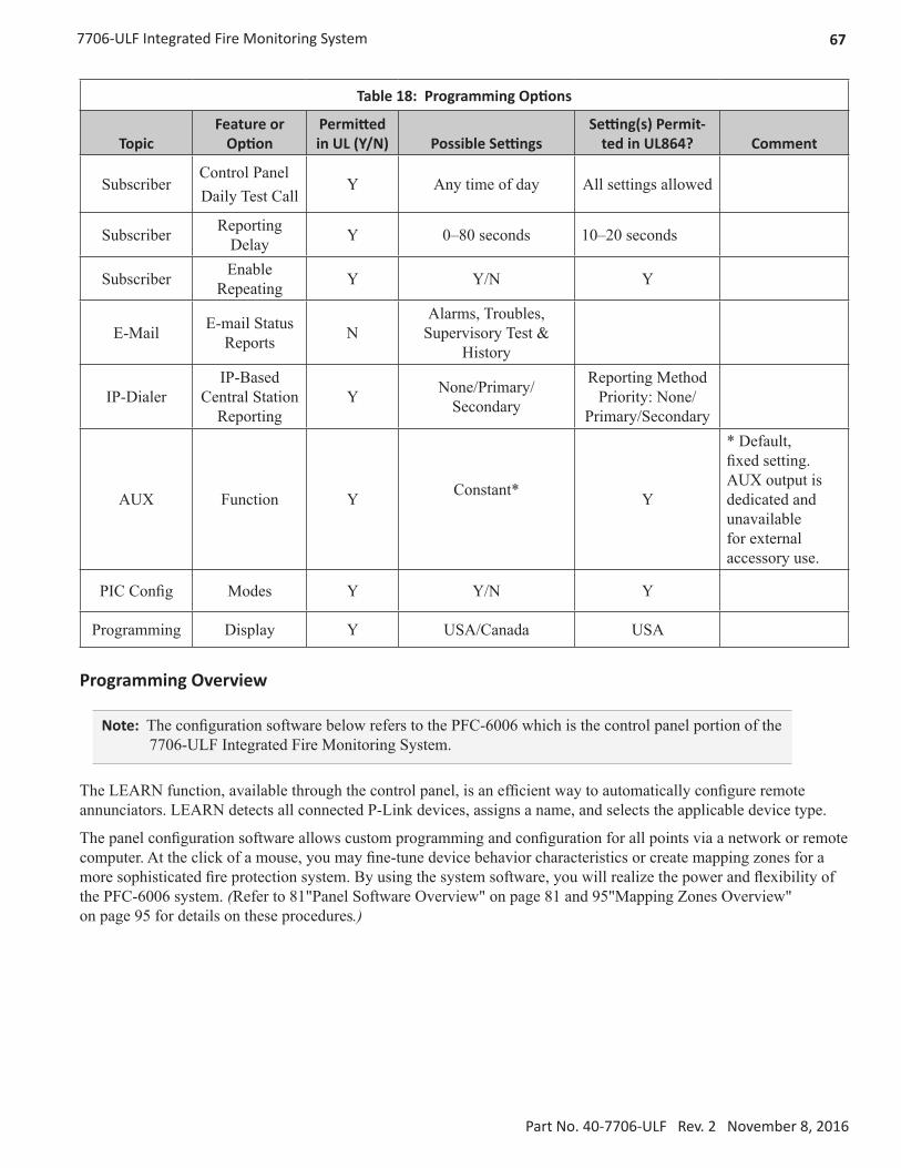
677706-ULF Integrated Fire Monitoring System
Part No. 40-7706-ULF Rev. 2 November 8, 2016
Table 18: Programming Options
TopicFeature or
OptionPermitted in UL (Y/N) Possible Settings
Setting(s) Permit-ted in UL864? Comment
SubscriberControl PanelDaily Test Call
Y Any time of day All settings allowed
Subscriber Reporting Delay Y 0–80 seconds 10–20 seconds
Subscriber Enable Repeating Y Y/N Y
E-Mail E-mail Status Reports N
Alarms, Troubles, Supervisory Test &
History
IP-DialerIP-Based
Central Station Reporting
Y None/Primary/Secondary
Reporting Method Priority: None/
Primary/Secondary
AUX Function Y Constant* Y
* Default, fixed setting. AUX output is dedicated and unavailable for external accessory use.
PIC Config Modes Y Y/N Y
Programming Display Y USA/Canada USA
Programming Overview
Note: The configuration software below refers to the PFC-6006 which is the control panel portion of the 7706-ULF Integrated Fire Monitoring System.
The LEARN function, available through the control panel, is an efficient way to automatically configure remote annunciators. LEARN detects all connected P-Link devices, assigns a name, and selects the applicable device type.
The panel configuration software allows custom programming and configuration for all points via a network or remote computer. At the click of a mouse, you may fine-tune device behavior characteristics or create mapping zones for a more sophisticated fire protection system. By using the system software, you will realize the power and flexibility of the PFC-6006 system. (Refer to 81"Panel Software Overview" on page 81 and 95"Mapping Zones Overview" on page 95 for details on these procedures.)

68 7706-ULF Integrated Fire Monitoring System
Part No. 40-7706-ULF Rev. 2 November 8, 2016
The Programming Cycle
The following approach is recommended for programming the system, if not using the default setup:
1. Install software.
2. Connect Ethernet cable.
3. Upload data to the computer.
4. Program the system.
5. Download configuration file.
Note: This approach may eliminate programming errors; however, these are only recommendations.
Software Installation
It's easy to install the PFC-6006 software and requires only a few minutes to complete. Once done, the program automatically creates a shortcut icon on your desktop for easy access.
The system software is compatible with Windows XP, Windows Vista, and Windows 7 Operating Systems, and it incorporates conventional shortcuts and features (i.e., right-click to display shortcut menus, drag and drop, etc.). The software’s flexibility enables you to effectively program individual and/or groups of points. Several examples in configuring a basic fire system are provided in 95"System Programming" on page 95.
Note: The latest version of Microsoft .NET Framework is required.
To install the software:
y Access the Potter website at http://www.pottersignal.com and locate the appropriate link to begin the software download.
y The default installation directory is C:\ProgramFiles\Potter\Potter Fire Panel Programmer. y You may change the location of the application files.
LEARN Programming
The LEARN mode enables you to efficiently configure all connected, addressed remote annunciators. Only authorized users may access this function. LEARN generates a list of all remote annunciators, which may be viewed on a remote computer. (Refer to 101"Configuring Points" on page 101 and 95"Mapping Zones Overview" on page 95 for details.)
To run the LEARN mode:
1. From the control panel, press Enter to display the Main Menu.
• Press 6 to select Programming. The Enter Code prompt displays.
• Enter the user code as prompted.
• Press 2 to select LEARN. The P-Link Initializing prompt displays, and the system begins the initialization process.
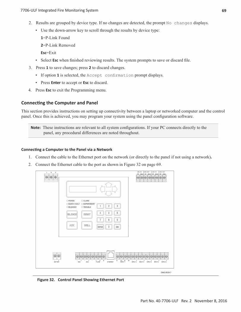
697706-ULF Integrated Fire Monitoring System
Part No. 40-7706-ULF Rev. 2 November 8, 2016
2. Results are grouped by device type. If no changes are detected, the prompt No changes displays.
• Use the down-arrow key to scroll through the results by device type:
1=P-Link Found
2=P-Link Removed
Esc=Exit
• Select Esc when finished reviewing results. The system prompts to save or discard file.
3. Press 1 to save changes; press 2 to discard changes.
• If option 1 is selected, the Accept confirmation prompt displays.
• Press Enter to accept or Esc to discard.
4. Press Esc to exit the Programming menu.
Connecting the Computer and Panel
This section provides instructions on setting up connectivity between a laptop or networked computer and the control panel. Once this is achieved, you may program your system using the panel configuration software.
Note: These instructions are relevant to all system configurations. If your PC connects directly to the panel, any procedural differences are noted throughout.
Connecting a Computer to the Panel via a Network
1. Connect the cable to the Ethernet port on the network (or directly to the panel if not using a network).
2. Connect the Ethernet cable to the port as shown in Figure 32 on page 69.L N G
BATTERY- +
NAC - +
AUX+-
P-LINK+- BA
ETHERNET INPUT 1A- A+ B- -B+ -+ -+ -+ -+ +
INPUT 2 INPUT 3 INPUT 4 INPUT 5 INPUT 6
TIP RING TIP RING TIP RING TIP RING
LINE 2 OUTLINE 2 IN LINE 1 OUTLINE 1 IN
DWG #559-7
Figure 32. Control Panel Showing Ethernet Port
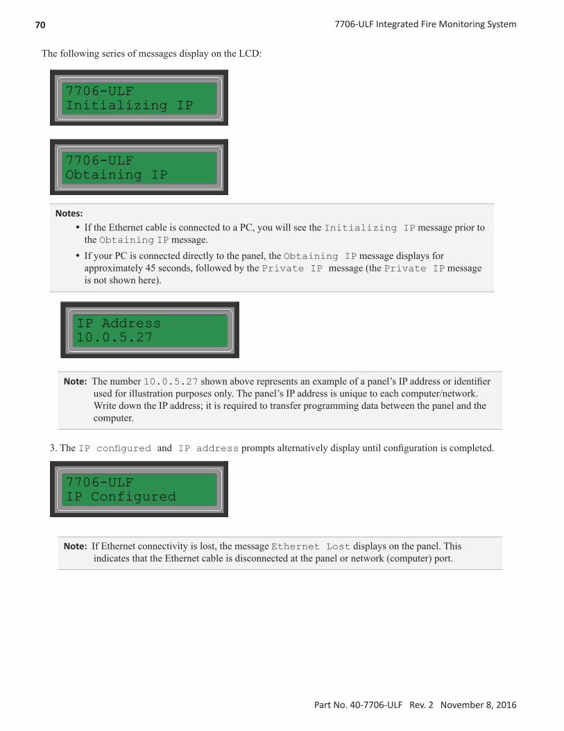
70 7706-ULF Integrated Fire Monitoring System
Part No. 40-7706-ULF Rev. 2 November 8, 2016
The following series of messages display on the LCD:
7706-ULFInitializing IP
D77065020900
7706-ULFObtaining IP
D77065021000
Notes: y If the Ethernet cable is connected to a PC, you will see the Initializing IP message prior to the Obtaining IP message.
y If your PC is connected directly to the panel, the Obtaining IP message displays for approximately 45 seconds, followed by the Private IP message (the Private IP message is not shown here).
IP Address10.0.5.27
D77065021100
Note: The number 10.0.5.27 shown above represents an example of a panel’s IP address or identifier used for illustration purposes only. The panel’s IP address is unique to each computer/network. Write down the IP address; it is required to transfer programming data between the panel and the computer.
3. The IP configured and IP address prompts alternatively display until configuration is completed.
7706-ULFIP Configured
D77065021200
Note: If Ethernet connectivity is lost, the message Ethernet Lost displays on the panel. This indicates that the Ethernet cable is disconnected at the panel or network (computer) port.

717706-ULF Integrated Fire Monitoring System
Part No. 40-7706-ULF Rev. 2 November 8, 2016
Transferring Data
This section provides step-by-step instructions for uploading and downloading data transfers. The transfer icons are located at the top of the Programmer window and are briefly described below.
Table 19: Transfer Functions
Icons Description
Downloads configuration file from the computer to the panel.
Uploads the configuration file from the panel to the computer.
Uploads the history events file from the panel to the computer.
Prints the selected file.
The Transfers region is located at the bottom of the Programmer window and lists all completed transfers. This area displays transfer details, including the date and time. You may also access the Transfer shortcut menu from this location to select any of the transfer functions.
The "Transfer" window displays allcompleted transfers.
Figure 33. Example of Programming Window Showing Transfer Icons and Transfer Section
Note: Double-click anywhere on the transfer record to view details.

72 7706-ULF Integrated Fire Monitoring System
Part No. 40-7706-ULF Rev. 2 November 8, 2016
Uploading from Panel to Computer
The Upload Configuration File to Computer transfer icon is used to upload the configuration file from the panel to the computer once the LEARN function is completed or whenever points are added to or removed from the panel.
To upload programming changes to computer:
1. Click the Upload Configuration File to Computer icon or right-click from the Transfers region as shown Figure 34:
Right click anywhere in thetransfer window to displaythe shortcut menu.
Figure 34. Example of Transfer Shortcut Menu
2. Click the Add option from the shortcut menu to choose the transfer type.
The Transfer dialog box displays.
Figure 35. Example of Transfer Upload Dialog Box
3. Verify that Upload is selected in the Transfer Type field.
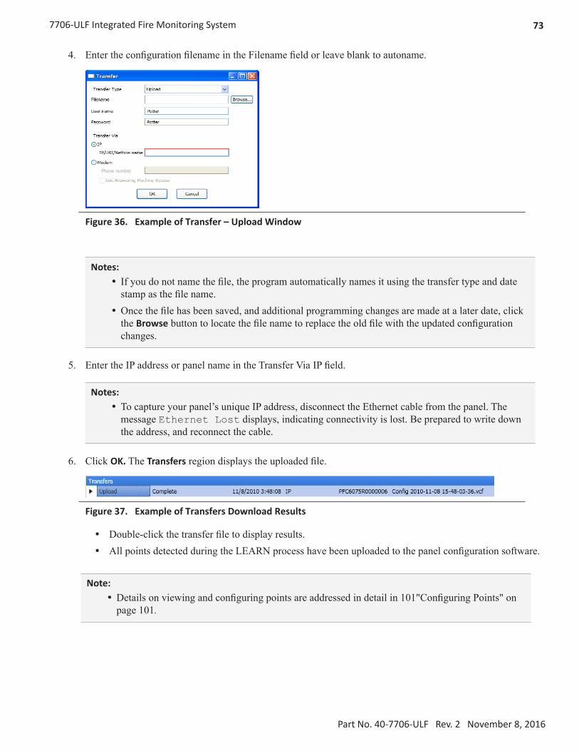
737706-ULF Integrated Fire Monitoring System
Part No. 40-7706-ULF Rev. 2 November 8, 2016
4. Enter the configuration filename in the Filename field or leave blank to autoname.
Figure 36. Example of Transfer – Upload Window
Notes: y If you do not name the file, the program automatically names it using the transfer type and date stamp as the file name.
y Once the file has been saved, and additional programming changes are made at a later date, click the Browse button to locate the file name to replace the old file with the updated configuration changes.
5. Enter the IP address or panel name in the Transfer Via IP field.
Notes: y To capture your panel’s unique IP address, disconnect the Ethernet cable from the panel. The message Ethernet Lost displays, indicating connectivity is lost. Be prepared to write down the address, and reconnect the cable.
6. Click OK. The Transfers region displays the uploaded file.
Figure 37. Example of Transfers Download Results
y Double-click the transfer file to display results. y All points detected during the LEARN process have been uploaded to the panel configuration software.
Note: y Details on viewing and configuring points are addressed in detail in 101"Configuring Points" on page 101.

74 7706-ULF Integrated Fire Monitoring System
Part No. 40-7706-ULF Rev. 2 November 8, 2016
Downloading Configuration File to Panel
The Download Configuration File to Panel icon allows you to copy all programming changes to the panel.
Notes: y Be sure to "Enable Remote Access" (as shown below) at the panel before choosing this option. If your PC is directly connected to the panel versus a network, this step is not necessary.
y Verify that the remote user name and password match the panel’s user name and password. You will receive an error message when attempting to download data to the panel if they do not match.
Enable Remote Access
To enable remote access:
1. At the control panel, press ENTER to display the Main Menu.
2. Press 7 to select Data Transfer.
3. The Enter Code prompt displays. Enter the user code to continue.
4. The Select Data option displays. Press 1 to select Remote Access.
5. Press ESC to return to the Main Menu.
Note: Once enabled, the remote access will time out after 30 minutes if contact is not established.
File New
The File New menu option is used to complete all programming from scratch on the computer. You must select the correct panel model prior to programming.
Note: It is imperative that you choose the correct panel model prior to programming or completing any data transfers; otherwise, you cannot complete a successful download to the panel. If this occurs, you will have to reprogram the entire panel.
Figure 38. Example of File New Dialog Box

757706-ULF Integrated Fire Monitoring System
Part No. 40-7706-ULF Rev. 2 November 8, 2016
File Save / Save As
Once programming has been completed, save your configuration file using either the File > Save or File > Save As function. An audit is performed that checks for rule violations; if errors are encountered, you may choose to either save with errors or cancel the save operation.
Figure 39. Example of Save Panel Dialog Box
Notes: y All site-specific configuration data is stored in the panel’s non-volatile memory. y The next time you make programming changes, you may overwrite the original configuration file with changes. If you choose to do this, you will lose the original programming report information.
y The panel configuration file has a .fpcf file extension.
Audit Errors
The Audit Error - Save anyway? dialog box displays if programming errors are encountered when saving the configuration file. You may choose to save the file with errors; however, you cannot download the data until all errors have been corrected.
Figure 40. Example of the "Save anyway?" Dialog Box

76 7706-ULF Integrated Fire Monitoring System
Part No. 40-7706-ULF Rev. 2 November 8, 2016
Downloading a Configuration File
To download the configuration file:
1. Click the Download Configuration File to Panel icon or right-click from the Transfers region, then click Add.
The Transfer dialog box displays.
Figure 41. Example of Transfer – Download Dialog Box
2. Verify that Download is selected in the Transfer Type field.
3. Enter the file name in the Filename field or click the Browse button to select the file name.
4. Enter the IP address in the IP field (under Transfer Via).
Note: To capture the panel’s unique IP address: 1. Disconnect the Ethernet cable from panel. 2. The message “Ethernet Lost" displays indicating connectivity is lost. 3. Reconnect the cable, and write down the IP address shown.
Figure 42. Transfer—Download Dialog Box

777706-ULF Integrated Fire Monitoring System
Part No. 40-7706-ULF Rev. 2 November 8, 2016
5. Click OK. The Transfers window displays the transfer progress.
Figure 43. Example of Transfers Window Showing Download Completed
Uploading History Events Status Reports
The Upload History File to Computer icon allows you to view valuable information that can be essential when analyzing system operations. You may choose to print the History reports by using the Print icon; reports can be scheduled to be automatically sent to authorized e-mail addresses. Refer to "System E-mail Functions" on page 86 for details on programming this e-mail reporting option.
History Reports
The Event History transfer option creates a report of all events held in the panel’s buffer. Up to 1,000 events are held in the buffer at one time. This information may be used to troubleshoot errors or to assess ways to improve the system configuration.
To transfer event history information:
1. Click the Upload History File to Computer icon or right-click from the Transfers area, and click Add. The Transfer dialog box displays.
2. Verify that History is selected in the Transfer Type field, and click OK to display the results.
Figure 44. Transfer Window Results

78 7706-ULF Integrated Fire Monitoring System
Part No. 40-7706-ULF Rev. 2 November 8, 2016
3. Double-click file to view results.
Figure 45. Example of Transfer Results Window
Note: Click the Print icon to print a copy of the report. Refer to "" on page 78 for more details.
4. Click the close button to close the report.
Note: Refer to "Receiving E-mail Status Reports" on page 92 for a sample of a History Events Report sent via e-mail.

797706-ULF Integrated Fire Monitoring System
Part No. 40-7706-ULF Rev. 2 November 8, 2016
Printing Reports
The Print icon allows you to print History reports. Double-click the History file listed in the Transfer window prior to clicking the Print icon. An example of the Report window, which displays a History report, is shown below:
Move the mouse across the Print icons to display their descriptions.
Figure 46. Example of the History Report (Print) Window

80 7706-ULF Integrated Fire Monitoring System
Part No. 40-7706-ULF Rev. 2 November 8, 2016
To print a History Report:
1. Double-click the History report listed in the Transfers window to display the report.
2. Adjust the width of the Event column to display the entire descriptions; otherwise, the Event information will be truncated on the printed report.
Tip: Double-click on the Event column's border to automatically expand the width to accommodate the longest description. Refer to the example below.
Double-click here to adjust the column width based on the longest event description.
Figure 47. Example of the History Report
3. Click the Print icon, then click the Report Print icon or CTRL P to open the Print dialog box.
4. Click the Print button.

817706-ULF Integrated Fire Monitoring System
Part No. 40-7706-ULF Rev. 2 November 8, 2016
Panel Software Overview
This section gives you an overview of the Panel Configuration Software. It addresses navigating through the program windows, understanding the purpose of icons and program features, and using Window’s conventional editing techniques and other program shortcuts to efficiently configure your system.
Window Regions / Areas
When you select a function from the Panel window, the related information displays on the right. Additionally, the selected function is highlighted, which helps direct your eye to the function's related screen information. For example, when Remote Access Code is selected, the remote user name and password displays. Please refer to the examples shown in Figure 48 and Figure 49.
Figure 48. Panel Menu Options
Figure 49. Example of Remote Access Code

82 7706-ULF Integrated Fire Monitoring System
Part No. 40-7706-ULF Rev. 2 November 8, 2016
Program Icons
The panel software uses several standard Windows icons, such as the close button and scroll bars. There are others that are unique to the panel software, such as auto hide and window position which are summarized in the table below:
Table 20: Panel Configuration Icons
Name Icon Description/Function
Window Position
Located in the upper right region of some windows.Click the icon to choose an option:• Floating – Window floats over other windows; right-click title bar to reselect
dockable.
• Dockable – Default window position; window is “locked” in place.
• Auto Hide – Window is hidden when cursor is moved and “tab” displays as window placeholder; point to window “tab” to redisplay (window tab is explained below).
Auto-Hide
Shortcut to hide a window.
• Click to hide window.
• Icon changes to (insert window autohide if window is hidden.
• Click to unhide and dock window.
Window “Tab”
Displays if window is hidden; available for specific windows only.
Note: “Tab” name is specific to the hidden window.• Point to “tab” to display window.• Point or click in another window to hide.
Tab

837706-ULF Integrated Fire Monitoring System
Part No. 40-7706-ULF Rev. 2 November 8, 2016
Table 20: Panel Configuration Icons
Name Icon Description/Function
Expand/Collapse
Available in Zones and Points windows only.
• Click the "plus" sign to expand.
• Click the "minus" sign to collapse.
Programming Functions Overview
The table below gives you a snapshot of the menu order along with a brief description of each. Details for these options are provided on the following pages.
Table 21: Programming Menu Overview
Menu Option DescriptionRemote Access Code Displays remote access “User Name” and “Password”.
Job Details Allows site-specific information to be entered.
General Options Allows software’s general panel settings to be customized.
Zones Define and configure zone’s characteristics and mapping points.
Points Define and view all addressable and non-addressable points.
Email Reporting Schedule e-mail reports by day and time, set up e-mail addresses, and select type of report(s) to send to each e-mail addressee.
Email Reminders Create and schedule customized daily, weekly, monthly, or yearly reminder emails.
Users Create up to ten user codes and passwords, and set access rights.
LAN Settings Configure Ethernet connectivity options.
Dialer Configure the on-board DACT reporting accounts and phone options.
Annunciators Add or remove remote annunciators.
IP Reporting Configure IP reporting options for primary and secondary accounts.

84 7706-ULF Integrated Fire Monitoring System
Part No. 40-7706-ULF Rev. 2 November 8, 2016
Remote Access Code
The Panel Configuration window displays the remote access user name and password on the right section of the screen (refer to the example shown below).
Figure 50. Example of the Panel Configuration Screen
User Name / Password
The default user name and password is Potter as shown below; they can be changed to ensure that only authorized personnel can transfer data to and from the panel.
Figure 51. Remote Access Code Screen
Notes: y The remote access user name and password may be changed to increase security on the system. y The remote user name and password must match the panel’s user name and password.

857706-ULF Integrated Fire Monitoring System
Part No. 40-7706-ULF Rev. 2 November 8, 2016
General System Functions
Job Details
Site-specific information, such as company name, address, and phone numbers, may be entered in this window. This information is stored in the panel and is used to identify the panel when using e-mail reporting options. Please refer to the figure shown below.
To enter site information:
1. Click the Job Details program option. The Job Details window displays.
Figure 52. Job Details Window
2. Click in each applicable field to enter information.
Note: You may also press the Tab key to move to the next field.

86 7706-ULF Integrated Fire Monitoring System
Part No. 40-7706-ULF Rev. 2 November 8, 2016
NOTICESystem e-mail communications and functions are intended for informational reporting purposes only. They are intended to be used as a convenience function. E-mail communications should NOT be used as a primary means of reporting emergency information.
System E-mail Functions
The PFC-6006 comes with built-in e-mail capabilities. The panel automatically sends status e-mails, including Alarms, Troubles, Supervisory, and Test events, to the e-mail addresses designated on the E-mail Reporting window as shown below.
Alarm, Trouble, Supervisory and Test Events are sent immediately as theyoccur!
If selected, Event History Reports will be sent based on the weekly schedule, timeand day of the month indicated here.
Figure 53. E-mail Reporting Window
Event History reports may be scheduled to be sent on specific days of the week, time, or day of the month. Up to 20 e-mail addresses may be programmed on this screen. After the E-mail Reporting section is completed and downloaded into the panel, the panel will start sending e-mails according to programming.
The panel is capable of sending automatic and on-demand reports because it has a designated outgoing e-mail address comprised of its model and serial numbers. On-demand reports can be requested directly from the panel's Data Transfer function or remotely from a PC, if the user has a valid e-mail address programmed on the E-mail Reporting window.
The panel address is structured as [email protected], where PFC6XXXXXXXXXXX refers to the panel serial number. The serial number is the same as the NetBIOS name, and is located on the panel as shown below.
Note: Outgoing panel e-mails are routed through a dedicated Potter server. You must make a notation of your panel's outgoing e-mail address in order to send e-mail requests remotely.

877706-ULF Integrated Fire Monitoring System
Part No. 40-7706-ULF Rev. 2 November 8, 2016
NOTICESystem e-mail communications and functions are intended for informational reporting purposes only. They are intended to be used as a convenience function. E-mail communications should NOT be used as a primary means of reporting emergency information.
BAR CODEPFC6xxxxxxxxx
Panel Serial Number
DWG #559-11
Figure 54. Panel Serial Number Location
P-Link E-mail Notification Requirements
The following table lists the necessary hardware and Internet connectivity requirements to use P-Link functions, such as e-mail notification.
Table 22: P-Link E-mail Notification RequirementsItem Requirement
Hardware 10/100 Mbps Ethernet Network
IP Address Protocol DHCP or Static IP (factory default is DHCP)
Outbound ConnectivityMust have outbound access to Internet (mail server connections only).Port 10025 for SMTPPort 110 for POP3
Inbound Connectivity None required or utilized.
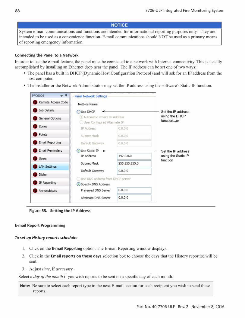
88 7706-ULF Integrated Fire Monitoring System
Part No. 40-7706-ULF Rev. 2 November 8, 2016
NOTICESystem e-mail communications and functions are intended for informational reporting purposes only. They are intended to be used as a convenience function. E-mail communications should NOT be used as a primary means of reporting emergency information.
Connecting the Panel to a NetworkIn order to use the e-mail feature, the panel must be connected to a network with Internet connectivity. This is usually accomplished by installing an Ethernet drop near the panel. The IP address can be set one of two ways:
y The panel has a built in DHCP (Dynamic Host Configuration Protocol) and will ask for an IP address from the host computer.
y The installer or the Network Administrator may set the IP address using the software's Static IP function.
Set the IP addressusing the Static IP function
Set the IP addressusing the DHCP function...or
Figure 55. Setting the IP Address
E-mail Report Programming
To set up History reports schedule:
1. Click on the E-mail Reporting option. The E-mail Reporting window displays.
2. Click in the Email reports on these days selection box to choose the days that the History report(s) will be sent.
3. Adjust time, if necessary.
Select a day of the month if you wish reports to be sent on a specific day of each month.
Note: Be sure to select each report type in the next E-mail section for each recipient you wish to send these reports.

897706-ULF Integrated Fire Monitoring System
Part No. 40-7706-ULF Rev. 2 November 8, 2016
NOTICESystem e-mail communications and functions are intended for informational reporting purposes only. They are intended to be used as a convenience function. E-mail communications should NOT be used as a primary means of reporting emergency information.
To set up addresses and select events and/or reports:
1. In the E-mail address section, as shown below, enter up to 20 e-mail addresses, if needed.
2. Select the Enable E-mail Requests option if the e-mail addressee may request reports from the panel.
Note: If Enable E-mail Requests is not selected, the panel will ignore e-mail request for an on-demand report.
3. Select each type of event(s) and/or report(s) you wish to send to the applicable e-mail address.
4. A checkmark “” displays in each selected report type.
Important Note: The "Enable E-mailRequests" option must be selected inorder for the panel to respond to ane-mail addressee requesting an ondemandreport.
Figure 56. E-mail Reporting showing Enable E-mail Request
E-mail Sent from Panel
To send a report from the panel:
1. Select Data Transfer (Menu Option 7) on the panel menu.
2. Select one of the transfer options as described below:
Table 23: Data Transfer OptionsOption Description
1=Remote Access Used to enable remote access2=E-mail History Allows user to e-mail a history file 3=E-mail Config Allows user to e-mail a panel configuration file (.fpcf)4=E-mail Test Allows user to send a test e-mail5=Server Status Allows e-mail server status to be verified

90 7706-ULF Integrated Fire Monitoring System
Part No. 40-7706-ULF Rev. 2 November 8, 2016
NOTICESystem e-mail communications and functions are intended for informational reporting purposes only. They are intended to be used as a convenience function. E-mail communications should NOT be used as a primary means of reporting emergency information.
3. Select one or more e-mail addresses using one of the following options:
y Choose Use Default to select the address entered in General Options (as shown below). y Choose Browse List to scroll through and select one or more e-mail addresses entered in E-mail
Reporting. y Choose Specify New to enter additional e-mail addresses, if needed.
Use the “Default”outgoing e-mailaddress.
Figure 57. Example of the General Options Window - Default Outgoing E-mail Address
E-mail Report Requested from PC
To request a report from a remote PC:
1. Open or create a new e-mail.
2. In the To field, enter the panel's e-mail address as shown in Figure 58. (Refer also to 87"Figure 54. Panel Serial Number Location" on page 87.)
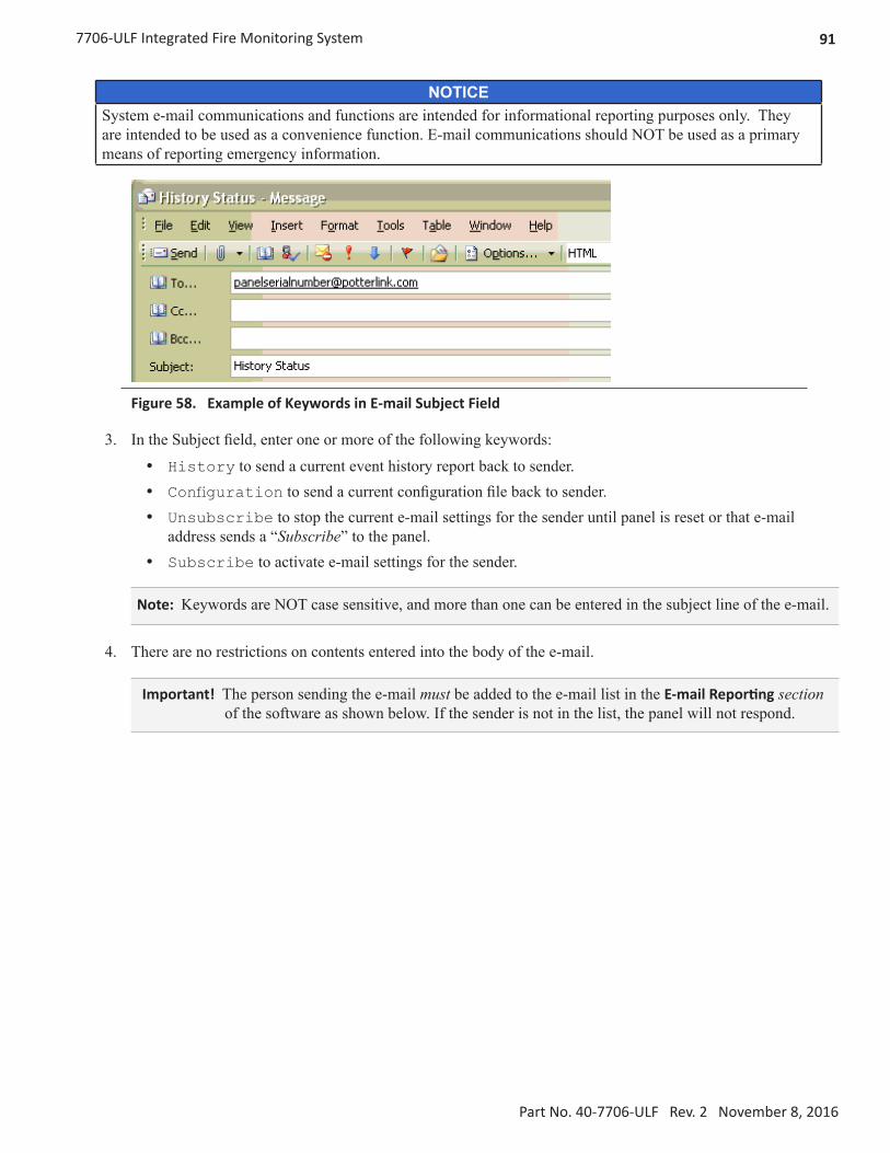
917706-ULF Integrated Fire Monitoring System
Part No. 40-7706-ULF Rev. 2 November 8, 2016
NOTICESystem e-mail communications and functions are intended for informational reporting purposes only. They are intended to be used as a convenience function. E-mail communications should NOT be used as a primary means of reporting emergency information.
Figure 58. Example of Keywords in E-mail Subject Field
3. In the Subject field, enter one or more of the following keywords:
y History to send a current event history report back to sender. y Configuration to send a current configuration file back to sender. y Unsubscribe to stop the current e-mail settings for the sender until panel is reset or that e-mail
address sends a “Subscribe” to the panel. y Subscribe to activate e-mail settings for the sender.
Note: Keywords are NOT case sensitive, and more than one can be entered in the subject line of the e-mail.
4. There are no restrictions on contents entered into the body of the e-mail.
Important! The person sending the e-mail must be added to the e-mail list in the E-mail Reporting section of the software as shown below. If the sender is not in the list, the panel will not respond.
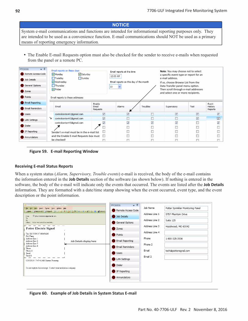
92 7706-ULF Integrated Fire Monitoring System
Part No. 40-7706-ULF Rev. 2 November 8, 2016
NOTICESystem e-mail communications and functions are intended for informational reporting purposes only. They are intended to be used as a convenience function. E-mail communications should NOT be used as a primary means of reporting emergency information.
y The Enable E-mail Requests option must also be checked for the sender to receive e-mails when requested from the panel or a remote PC.
Sender's e-mail must be in the e-mail list and the Enable E-mail Requests box must be checked!
Note: You may choose not to select a specific event type or report for an e-mail address.If so, choose Browse List from the Data Transfer panel menu option. Then scroll through e-mail addresses and select one or more recipients.
Figure 59. E-mail Reporting Window
Receiving E-mail Status Reports
When a system status (Alarm, Supervisory, Trouble events) e-mail is received, the body of the e-mail contains the information entered in the Job Details section of the software (as shown below). If nothing is entered in the software, the body of the e-mail will indicate only the events that occurred. The events are listed after the Job Details information. They are formatted with a date/time stamp showing when the event occurred, event type, and the event description or the point information.
Job Details display here
Figure 60. Example of Job Details in System Status E-mail

937706-ULF Integrated Fire Monitoring System
Part No. 40-7706-ULF Rev. 2 November 8, 2016
NOTICESystem e-mail communications and functions are intended for informational reporting purposes only. They are intended to be used as a convenience function. E-mail communications should NOT be used as a primary means of reporting emergency information.
When a history status e-mail is received it contains two attachments:
• A text file (.txt)
• A comma separated values (.csv) file
Figure 61. Examples of a History text file (.txt) & History Comma Separated Value file
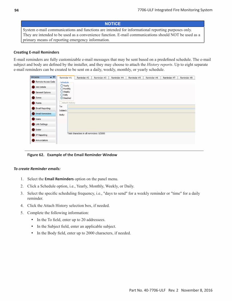
94 7706-ULF Integrated Fire Monitoring System
Part No. 40-7706-ULF Rev. 2 November 8, 2016
NOTICESystem e-mail communications and functions are intended for informational reporting purposes only. They are intended to be used as a convenience function. E-mail communications should NOT be used as a primary means of reporting emergency information.
Creating E-mail Reminders
E-mail reminders are fully customizable e-mail messages that may be sent based on a predefined schedule. The e-mail subject and body are defined by the installer, and they may choose to attach the History reports. Up to eight separate e-mail reminders can be created to be sent on a daily, weekly, monthly, or yearly schedule.
Figure 62. Example of the Email Reminder Window
To create Reminder emails:
1. Select the Email Reminders option on the panel menu.
2. Click a Schedule option, i.e., Yearly, Monthly, Weekly, or Daily.
3. Select the specific scheduling frequency, i.e., "days to send" for a weekly reminder or "time" for a daily reminder.
4. Click the Attach History selection box, if needed.
5. Complete the following information:
y In the To field, enter up to 20 addressees. y In the Subject field, enter an applicable subject. y In the Body field, enter up to 2000 characters, if needed.

957706-ULF Integrated Fire Monitoring System
Part No. 40-7706-ULF Rev. 2 November 8, 2016
NOTICESystem e-mail communications and functions are intended for informational reporting purposes only. They are intended to be used as a convenience function. E-mail communications should NOT be used as a primary means of reporting emergency information.
Figure 63. Example of Creating a Daily Reminder
6. Continue setting up additional reminders if needed.
System Programming
System programming involves defining the function of points and their relationships to each other, referred to as "mapping." You can define behavior characteristics of individual or groups of points, map points into zones, and further customize your system using the panel configuration software from a computer.
The panel configuration software features include:
y Easy-to-use Windows-based editing techniques, including drag and drop between windows. y Flexibility in configuring points into multiple zones, promoting sophisticated mapping relationships. y Simple sorting and grouping by select fields enhances viewing and analysis of data. y Options to view points by type, address, and function or description.
Mapping Zones Overview
Mapping is creating relationships between points, modules, and sensors and their behavior between each other. Whereas, the “zone” is the framework in which you group the points. These terms and other related mapping concepts are provided in this section.
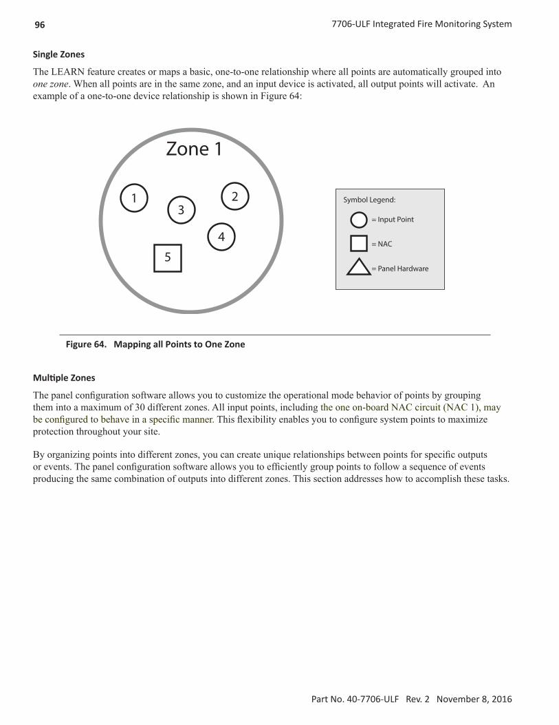
96 7706-ULF Integrated Fire Monitoring System
Part No. 40-7706-ULF Rev. 2 November 8, 2016
Single Zones
The LEARN feature creates or maps a basic, one-to-one relationship where all points are automatically grouped into one zone. When all points are in the same zone, and an input device is activated, all output points will activate. An example of a one-to-one device relationship is shown in Figure 64:
Zone 1
1 23
45
Symbol Legend:
= Input Point
= NAC
= Panel Hardware
Figure 64. Mapping all Points to One Zone
Multiple Zones
The panel configuration software allows you to customize the operational mode behavior of points by grouping them into a maximum of 30 different zones. All input points, including the one on-board NAC circuit (NAC 1), may be configured to behave in a specific manner. This flexibility enables you to configure system points to maximize protection throughout your site.
By organizing points into different zones, you can create unique relationships between points for specific outputs or events. The panel configuration software allows you to efficiently group points to follow a sequence of events producing the same combination of outputs into different zones. This section addresses how to accomplish these tasks.

977706-ULF Integrated Fire Monitoring System
Part No. 40-7706-ULF Rev. 2 November 8, 2016
Mapping Terminology
The table below provides mapping terms that may be helpful to you in understanding the mapping concept:
Table 24: Mapping Terminology
Term Definition
Mapping Creating relationships between points, modules, and sensors and defining their behavior.
Zone
A group of points.• Zones may represent a group of points located in a specific physical area at the site.
Example: Zone 1 comprised of all alarm devices for a sprinkler system [i.e., pull station #1, one water flow device, and one strobe-NAC].
• Zones may represent a set of points configured for a specific function; their location may be scattered throughout the site. This group is a logical grouping or zone.
Example: Zone 2 comprised of all points in Zone 1 as described above, plus a second pull station located at the end of a hallway and two additional smoke detectors.
Notes: y If all input/output points are grouped into one zone, when any input is activated, all outputs activate.
y A device or point may be mapped into more than one zone.
Point Any specific initiating device circuit (IDC) or appliance connected to the panel.
Latching Device will not automatically reset; device must be reset at the keypad to remove condition.
Non-Latching Device will automatically reset when trouble and supervisory condition is no longer present.
Zone Types / Styles
You may define or configure each zone to serve a specific purpose or to create specific output results. For procedures on how to select Zone styles, refer to the “Configuring Zones” section of this manual. The following zone styles are available:
Table 25: Zone Styles
Zone Description
Alarm Default zone type; sets system into an Alarm condition when any input is activated.
Supervisory Used for all Supervisory inputs.
Auxiliary Used for all “Aux” inputs.
Fire Drill Comprised of input / output points that will activate when running a Fire Drill.
System Alarm Used for outputs that will be activated upon any alarm.
System Supervisory Used for outputs that will be activated upon any supervisory.
System Trouble Used for outputs that will be activated upon any trouble.

98 7706-ULF Integrated Fire Monitoring System
Part No. 40-7706-ULF Rev. 2 November 8, 2016
Zone Attributes
Zone attributes are the settings that control the overall behavior of points within the zone. The zone may be configured as latching or non-latching, silenceable or non-silenceable, among other attributes.
Tip: Double-click in a field to modify an applicable field, i.e., zone name or alarm count. Click in fields with a selection box to select or deselect the option, i.e., silenceable or latching.
All zones default to an “Alarm” style or type when first created. The figure shown below is an example of the default attributes of an "Alarm" zone.
Figure 65. Example of Zone Attributes (Fields 1–5)
Refer to Table 26 for a brief explanation of zone attributes:
Table 26: Zone Attributes
Attribute Description
Zone NameDefault = Zone “x”(where “x” is a sequential number)
• Zone name may be up to 16 alphanumeric characters.
Latching / Non-LatchingDefault = Latching
• Available for one-count zones only.
• Latching zone requires operator to press Reset.
• Non-latching zone will automatically turn off outputs when condition clears.
Local / Non-LocalDefault = Non-Local
• Used only for the Report by Zone option.
• Allows a zone to be specified as a non-reporting zone.
Output PatternDefault = Constant
• Defines the output pattern of general-purpose NAC circuit in the zone that occurs during alarm conditions.
• Click on the drop-down arrow to display and select an option:
Constant 24 VDCANSI Temp 3 .5 sec on, .5 sec off, .5 sec on, .5 sec off, 5 sec on,
1.5 sec offMarch Code 60 signals per minuteDouble Time 120 signals per minute
Auto-Silence TimerDefault = 0 minutesRange = 0 – 360 minutes
Defines the amount of time before silenceable NAC is automatically shut down.

997706-ULF Integrated Fire Monitoring System
Part No. 40-7706-ULF Rev. 2 November 8, 2016
Table 26: Zone Attributes
Attribute Description
Auto-Unsilence TimerDefault = 0 minutesRange = 0 – 60 minutes
Defines the amount of time before any silenced NAC is reactivated; output only reactivate if panel is still in alarm.
Silence-Inhibit TimerDefault = 0 minutes Range = 0 – 60 minutes
Defines the amount of time you may not silence an output when in alarm.
Restore DelayDefault = 0 secondsRange = 0 – 300 seconds
Defines the amount of time before deactivating an output when the panel is reset.
Creating Zones
When creating zones, you may create one or more at a time. This section explains this process and includes examples for your convenience.
To create a zone:
1. In the Zones window, right-click on any zone name. The shortcut menu displays.
2. Click Add Zones. The Add Multiple Zones dialog box displays.
Figure 66. Examples of Adding Multiple Zones Dialog Box
3. In Number of Zones field, enter the number of zones to create.
Note: You may enter up to 30 zones.
4. In the Starting Zone Number field, enter the zone number to begin numbering zones, if different from default.
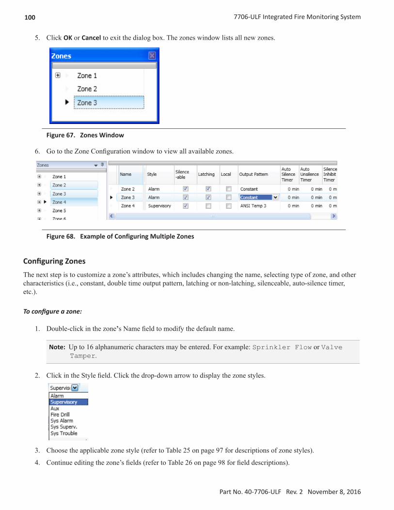
100 7706-ULF Integrated Fire Monitoring System
Part No. 40-7706-ULF Rev. 2 November 8, 2016
5. Click OK or Cancel to exit the dialog box. The zones window lists all new zones.
Figure 67. Zones Window
6. Go to the Zone Configuration window to view all available zones.
Figure 68. Example of Configuring Multiple Zones
Configuring Zones
The next step is to customize a zone’s attributes, which includes changing the name, selecting type of zone, and other characteristics (i.e., constant, double time output pattern, latching or non-latching, silenceable, auto-silence timer, etc.).
To configure a zone:
1. Double-click in the zone’s Name field to modify the default name.
Note: Up to 16 alphanumeric characters may be entered. For example: Sprinkler Flow or Valve Tamper.
2. Click in the Style field. Click the drop-down arrow to display the zone styles.
3. Choose the applicable zone style (refer to Table 25 on page 97 for descriptions of zone styles).
4. Continue editing the zone’s fields (refer to Table 26 on page 98 for field descriptions).

1017706-ULF Integrated Fire Monitoring System
Part No. 40-7706-ULF Rev. 2 November 8, 2016
Configuring Points
This section addresses how to define or configure points through the Points function. Each device may have a unique function in relation to the zone as well as the entire system. The user determines the Point's role, specific behavior characteristics, and customizes its name, if desired.
Notes: y The list of available functions is associated with the device type. y Points may be configured from either the Zones or Points functions; however, for purposes of this manual, points are configured in the Points function.
y Points can be configured individually, or by groups or ranges of points.
An example of the Points window is shown below.
Figure 69. Example of Points Window
Input Circuit Functions
The IDC's ("Conventional Inputs") default to specific functions as shown in Table 28; however, they may be reconfigured and renamed, based on the following configuration functions:
Table 27: Input Circuit FunctionsFunction Description
Contact Input Pull Station Pull station input.
Contact Input Water Flow Water flow input obeys water flow delay as defined in General Options.
Contact Input Supervisory Supervisory input.
Contact Input Tamper Tamper input reports as supervisory.
Contact Input Fire Drill Fire drill input activates a fire drill.
Contact Input Trouble Monitor Trouble input creates a trouble condition.
Contact Input Aux Aux input reports as un-typed alarm.

102 7706-ULF Integrated Fire Monitoring System
Part No. 40-7706-ULF Rev. 2 November 8, 2016
The six Input or Initiating Device Circuits (IDC) automatically default as follows:
Table 28: Input Circuit's Default ConfigurationInput Circuit Default Function
Input 1 Water Flow
Input 2 Smoke Detector
Input 3 Manual Pull
Inputs 4 and 5 Supervisory
Input 6 Valve Tamper
NAC Functions
The on-board NAC circuit (NAC 1) is automatically configured as “Conv NAC General Purpose," but may be reconfigured to other functions, as described in Table 29.
Table 29: NAC Circuit Configuration FunctionsFunction Description
General Purpose General purpose NAC; obeys zone “output pattern” programming, and is the default.
Potter Sync Drives Potter synchronized horns/strobes.
Gentex Sync Drives Gentex synchronized horns/strobes.
System Sensor Sync Drives System Sensor synchronized horns/strobes.
Wheelock Sync Drives Wheelock synchronized horns/strobes.
AUX Functions
The on-board AUX circuit in the 7706-ULF Integrated Fire Monitoring System is configured to “Conv NAC Aux Constant." and cannot be changed. The AUX power circuit is unavailable for external accessory use. Refer to System Size Specifications section.
Table 30: AUX Circuit Configuration FunctionsFunction Description
Conv NAC Aux Constant Constant DC power; this is the default configuration for the 7706-ULF Integrated Fire Monitoring System and cannot be changed.

1037706-ULF Integrated Fire Monitoring System
Part No. 40-7706-ULF Rev. 2 November 8, 2016
To configure a single point:
1. Click on the Points function to display the Points Configuration window.
Figure 70. Example of a Configuration Window Showing Conventional Input Functions
Notes: y Points are listed by device addresses automatically. You may sort points by clicking on the column or field name, i.e., Name, Function, or Supervisory.
Example: Click the Function field to sort points alphabetically by device function.
y The list of available functions varies according to type of device(s) selected. y If you click the Supervisory field selection box, this designates that the contact will be a supervisory input versus an alarm input.
2. Click anywhere on the point you wish to configure.
Tip: The selected point is highlighted in blue and is also designated with an arrow symbol at the beginning of the point's line, as shown below.
3. Double-click in the Name field to enter a descriptive name, if wanted.
y Enter up to 16 alphanumeric characters.

104 7706-ULF Integrated Fire Monitoring System
Part No. 40-7706-ULF Rev. 2 November 8, 2016
4. Click the drop-down arrow at the end of the Function field to display the list of options.
Figure 71. Example of Configuring a Single Point
5. Continue configuring other points, as needed.
To configure a range of points:
1. Click the first point to configure from the Function field.
2. Press and hold the SHIFT key, then click in the Function field of the last point.
Figure 72. Example of Configuring a “Range” of Points
3. Right-click from the Function field to display the configuration options.
Notes: y If you right-click outside of the Function field, the range is deselected, and only one point will be configured.
y You may alternatively use the CTRL key to select multiple, non-adjacent points.
4. Click on device function from the shortcut menu.
5. Continue configuring other points, as needed.

1057706-ULF Integrated Fire Monitoring System
Part No. 40-7706-ULF Rev. 2 November 8, 2016
Adding Points to Zones
This section provides procedures and examples of adding points to one or more zones. Points can be moved and deleted from zones through the Zones panel by dragging and dropping. The examples shown in Figure 73, Figure 74, and Figure 75 illustrate how to use shortcuts to expedite configuring zones and to also reinforce the interaction between the Zones and Points windows.
To move one or more points into one zone:
1. Open the Zones configuration window and adjust the Points window to display full function name(s).
Points 4, 6, and 7 areselected.
Figure 73. Example of Resizing Points Window From Zone Screen
2. Click one or more points to select; use the SHIFT or CTRL keys to select a range or group of points.
3. Drag and drop the selected points from the Points window to the Device window. The selected points display in the Device window, as shown below.
Points 4, 6, and 7are con�gured into Zones 2 and 3.
Figure 74. Example of Configuring Multiple Points into Multiple Zones

106 7706-ULF Integrated Fire Monitoring System
Part No. 40-7706-ULF Rev. 2 November 8, 2016
4. Click “+” in the Points window to display point assignment by zone(s).
Figure 75. Example of Expanding Point’s Zone Assignment(s)
Note: Click “–” to collapse point assignments.

1077706-ULF Integrated Fire Monitoring System
Part No. 40-7706-ULF Rev. 2 November 8, 2016
Group by Area
You may group information by different fields in many of the program windows. This flexibility is helpful when configuring or viewing a large amount of information, such as all points, zones, or remote annunciators. Examples are included for illustration purposes only.
To group by area (field):
1. Click on the Group bar located at the top of the window, if available.
Click here to display "Group By Area".
Figure 76. Example of Points Window
The “group by area” prompt displays, as shown in Figure 77.
Figure 77. "Group by Area" Prompt
Note: Click the “group by area" bar at any time to collapse region.

108 7706-ULF Integrated Fire Monitoring System
Part No. 40-7706-ULF Rev. 2 November 8, 2016
2. Drag and drop one field into the “group by area” region. The information is displayed according to the selected field.
Figure 78. Example of Points Grouped by Function
Note: Click “+” next to the function to view a complete list of points. Click “-” to collapse the list of points, as needed.
Figure 79. Example of Expanded List of Grouped Points
Note: Click “–” to collapse point assignments.
3. Drag the field out of the “group by area” region to redisplay items in original order.

1097706-ULF Integrated Fire Monitoring System
Part No. 40-7706-ULF Rev. 2 November 8, 2016
Programming Points and Appliances
This section addresses how to program the P-Link appliances and points, including the on-board DACT and the RA-6075 annunciator.
On-Board DACT
Each system has a built-in DACT (Digital Alarm Communicator Transmitter). The DACT provides notification to a remote monitoring company when alarms, troubles, and supervisory conditions occur.
Programming options allow you to select separate accounts for test events and alarm, trouble, and supervisory conditions. You may set up telephone parameters, such as number of rings, when and where to send reports by specifying phone numbers, and other report output options. An example of the Add – Dialer window is shown.
These fields are important! Be sure to modify # of rings and line prefix fields according to your site's telephone setup! Refer to procedures on next page.
Figure 80. Example of DACT Add-Dialer Window
Notes: y A daily test is automatically sent to a remote monitoring location; the test time may be programmed through the General Options program window – “Time to Send Autotest” field.
y Once the panel has been programmed to use a dialer, and two phone lines are used, the DACT will alternate between lines on each daily call.
y If the IP Communicator is programmed, the daily test call can be sent to both reporting accounts. (Please refer to the IP Communicator Section for more information.)

110 7706-ULF Integrated Fire Monitoring System
Part No. 40-7706-ULF Rev. 2 November 8, 2016
Reporting Accounts
The “Reporting Accounts” section is used to program DACT operations and to customize the format of the reporting accounts. You may choose different settings for Alarms, Troubles, and Supervisory conditions. Up to five (5) primary and secondary reporting accounts may be configured.
To add and configure a DACT Dialer:
1. Select Dialer from the system panel, and click the Add Dialer button.
The Dialer window displays:
2. In the Reporting Method Priority field, set the applicable priority:
y Primary – The Dialer Reporting account and the AES mesh network are both used for communication to the remote monitoring station.
y Secondary – If the AES mesh network is unavailable, the Dialer Reporting account communicates with the remote monitoring station.
y No Selection – The Dailer Reporting account feature is not used.

1117706-ULF Integrated Fire Monitoring System
Part No. 40-7706-ULF Rev. 2 November 8, 2016
Remote Annunciators
The 7706-ULF supports one RA-6075 remote annunciator.
To add and configure a remote annunciator:
1. Select Annunciators from the system panel.
2. Click the Add Device button to display the Add Device window.
Figure 81. Example of Add Device Window
3. Double-click in the Name field to customize the name.
4. Double-click in the Address field to adjust the address, if needed.
Note: Only one annunciator may be connected to the system.

112 7706-ULF Integrated Fire Monitoring System
Part No. 40-7706-ULF Rev. 2 November 8, 2016
Verify Input and Output Points
The 7706-ULF System input and output points can be verified using the keypad and LCD display after panel installation and configuration. Use the following instructions to access and view key information.
1. At the 7706 –ULF Main menu screen, press 5, then press ENTER.
7706-ULF11/10 8:33:03AM
The program access screen appears.
Enter Code
2. Press 1111 as the access code. A series of *’s display for each number pressed.
Enter Code****
3. From the Tools menu, press 1 for Point Control.
Tools Menu1=Point Control
4. From the Select Device screen, press ENTER.
Select DeviceInternal PWR
5. Press ENTER at the Ckt (Circuit) screen (circuit 1 has been identified as the default point to examine).
Enter Ckt: 1
The point detail appears for selection 1, which is shown configured for a NAC.
NAC:GEN PURPOSE001 NORMAL
6. Press ESC to return to the Enter Ckt screen, and enter the next point number to examine using the keypad. If no more points need examination, press ESC again to return to the Tools menu.

1137706-ULF Integrated Fire Monitoring System
Part No. 40-7706-ULF Rev. 2 November 8, 2016
Examine Firmware Versions
Firmware versions used in the 7706-ULF System are visible through the LCD on the keypad.
LCD Control Firmware
The LCD control firmware drives the LCD display on the keypad. To view the firmware version of the LCD control, power on the panel. The firmware version is visible on the first screen displayed after power-up self-test is complete:
5670048 VX.XX where X.XX is the firmware version
7788F Subscriber Firmware
To view the 7788F Subscriber firmware version:
1. From the Main Menu display, press 5, then press Enter to access the System Tools menu. The Enter Code prompt displays.
2. Enter the user access code (1111).
3. At the System Tools menu, press 8 to select PIC Status. You are now in the PIC Menu.
4. Press 1 to select PIC Status. The screen displays the firmware for the 7788F Subscriber:
Type: SUBXX.XXXX 7788F where XX.XXXX is the firmware version
Mainboard and 7764 PIC Firmware
To view the mainboard and 7764 PIC firmware version:
1. From the Main menu display, press 5, then press ENTER to access the System Tools menu. The Enter Code prompt displays.
2. Enter the user access code (1111).
3. At the System Tools menu, press 7.
4. The screen displays the firmware version for the mainboard:
Control5670069 VX.XX where VX.XX is the mainboard firmware version
5. Press the DOWN ARROW. The screen displays the firmware version for the AES 7764 PIC.
AES PIC5670066 VX.XX where VX.XX is the AES 7764 PIC firmware version

114 7706-ULF Integrated Fire Monitoring System
Part No. 40-7706-ULF Rev. 2 November 8, 2016
Section 9. IP Communication
The system's built-in, on-board IP Communicator provides notification to a remote monitoring company when alarms, troubles, and supervisory conditions occur. The IP Communicator is used with an IP capable Sur-Gard receiver by means of the Fibro protocol.
Programming options allow you to select accounts for test events, as well as alarm, trouble, and supervisory conditions. You may set up IP parameters, such as when and where to send reports, by specifying IP addresses and other report output options. An example of the IP Reporting window is shown below:
Figure 82. Example of the IP Reporting Window
Notes: y A daily test can automatically be sent to a remote monitoring location; the test time may be programmed through the Time to Send Autotest field, located in the General Options program window.
y Where the fire alarm transmitter is sharing on-premises communications equipment, the shared equipment shall be UL listed.
y Secondary power shall be provided for all equipment necessary for the transmission and reception of alarm, supervisory, and trouble signals at the protected premises.
y Secondary power shall be provided for all equipment necessary for the transmission and reception of alarm, supervisory, and trouble signals at the supervising station.

1157706-ULF Integrated Fire Monitoring System
Part No. 40-7706-ULF Rev. 2 November 8, 2016
IP Reporting Accounts
This section describes how to program the IP Communicator operations, as well as how to customize the format of the reporting accounts. You may choose different settings for Alarms, Troubles, and Supervisory conditions. Up to five primary or secondary accounts may be configured.
To add and configure an IP Dialer:
1. Select IP Dialer from the system panel, and click the Add IP Reporting button.
The IP Reporting window displays:
2. In the Reporting Method Priority field, set the applicable priority:
y Primary – The IP Reporting account and the AES mesh network are both used for communication to the remote monitoring station.
y Secondary – If the AES mesh network is unavailable, the IP Reporting account communicates with the remote monitoring station.
y No Selection – The IP Reporting account feature is not used.
3. In the Panel UDP Port field, click to enter an incoming and outgoing UDP port. The UDP or User Data Protocol is the pathway for which data is sent and received between the panel and the remote monitoring station.
Note: The default UDP port is 3060; however, an alternate port number may be used. Check with your network administrator to determine if an alternate port number for FACP IP Reporting should be assigned.

116 7706-ULF Integrated Fire Monitoring System
Part No. 40-7706-ULF Rev. 2 November 8, 2016
4. In the IP Reporting Accounts, make the necessary selections for the primary and secondary reporting accounts:
y Select the report type(s): Alarms, Troubles, Supervisory
y Click on the Report By drop-down arrow to choose an option: Panel, Zone or Point
y Click on the Primary/Secondary Account Settings expand ellipsis icon to display additional setup options, as shown below:
Figure 83. Example of the IP Reporting Window
Notes: y Use the scroll bar to display additional fields if not shown on right. y Click the collapse icon at any time to hide the account setting fields.
y Enter the Account ID. y Select the applicable Primary Format option: CID/SIA
y Click in the Report Test Events selection box to send test signals to this account. y Double-click in the Receiver IP field, and enter the IP address provided by the remote monitoring
station. y Click on the Protocol drop-down arrow to select Fibro.
Note: Fibro communications is used with the Sur-Gard receiver.
y Double-click in the UDP Port field to enter the Primary/Secondary port number as provided by the remote monitoring station.
Note: The UDP port number is the pathway for data that the receiver receives from the system panel and sends to the system panel.
y Double-click in the Supervision Interval field to adjust the amount of time (in seconds) that the panel's IP Communicator will send a supervision signal to the remote monitoring receiver.
– Default setting is 20 seconds.
– Contact the remote monitoring station to verify the correct setting. The receiver is programmed with a specific window of time to "see" the supervision signal. If the supervision signal is not seen within the programmed time, the receiver generates a trouble signal after six failed communication attempts.
y Double-click in the Encryption Key field to enter an applicable number as provided by the remote monitoring station.
1177706-ULF Integrated Fire Monitoring System
Part No. 40-7706-ULF Rev. 2 November 8, 2016
y Click on the Encryption Method drop-down arrow to select 128 bit, if applicable.
Note: If Encryption Method is set to None, then an encryption key is not needed.
5. Click on the collapse icon to hide the account setting field when finished.
Reminder: Click the expand ellipsis icon to review or modify the account settings at any time.
6. Repeat steps for each Primary/Secondary reporting account or to edit an account.

118 7706-ULF Integrated Fire Monitoring System
Part No. 40-7706-ULF Rev. 2 November 8, 2016
Appendix A. Basic Operating Instructions
These instructions must be framed and displayed next to the 7706-ULF panel in accordance with NFPA-72 fire code for Local Protected Fire Alarm Systems. Test the system in accordance with NFPA-72.
Table A-1: Control Panel Function Keys
Description Function Keys
ACKNOWLEDGE
ARROW KEYS
FIRE DRILL
ESC
RESET
SIGNAL SILENCE
Table A-2: Operating Instructions
Operation Task
Silence Alarms, Troubles Press the SIGNAL SILENCE key.
Acknowledge Alarms, Troubles Press the ACKNOWLEDGE key after scrolling down to new event.
Reset Alarms Press the RESET key.
View Alarms, Troubles Press the arrow key(s) to view alarms/troubles.
Conduct a Fire Drill Press the FIRE DRILL key; press the RESET key to exit Drill mode.
View Point’s Status
• Press ENTER to display the Main Menu.• Press 5 – System Tools; enter the panel’s code.• Press 1 – Point Control.• Press ENTER to select Point.• Enter Addr/Ckt No. and press ENTER.• Press Up/Down to view previous/next points.

1197706-ULF Integrated Fire Monitoring System
Part No. 40-7706-ULF Rev. 2 November 8, 2016
Table A-2: Operating Instructions
Operation Task
Set Date/Time
• Press ENTER – Main Menu.• Press 3 – Set Date/Time.• Use the keypad to enter correct date; use right-arrow key to move
through the date field and to display the time field.
• Press ENTER to save changes.
Enable/Disable Point
• Press ENTER – Main Menu.• Press 2 – Enable/Disable; enter panel’s code.• Press 1 – By Point.• Enter Addr/Ckt No. and press ENTER.• Press Up/Down to scroll.• Point’s current status displays Normal (if enabled) or Disabled.• Press ENTER to change status; press ENTER to save or ESC to exit
without saving.
View Event History
• Press ENTER – Main Menu.• Press 1 – View History.• Press left/right arrow keys to view next/previous events.• Press the up/down arrow keys for a list of events.• Press ESC to exit.
For Service Call:

120 7706-ULF Integrated Fire Monitoring System
Part No. 40-7706-ULF Rev. 2 November 8, 2016
Appendix B. System Maintenance and Testing
Acceptance Test
The control panel is required to be installed in accordance with local and state building codes and NFPA-72 (National Fire Alarm Code). At the conclusion of each original installation or modification of this system, the control panel and related system is required to be inspected and tested in accordance with NFPA-72 to verify compliance with the applicable standards.
Testing should be conducted by trained fire alarm technician(s) from Potter factory in the presence of a representative of the Authority Having Jurisdiction (AHJ) and the building owners representative. Refer to NFPA-72 (National Fire Alarm Code), Inspection Testing and Maintenance code.
Periodic Testing and Service
Periodic testing and maintenance of the control panel, all initiating points, all notification appliances, and any other associated equipment is essential for ensuring that the system will operate as designed in emergency situations. Service and test the control panel according to the schedules and procedures outlined in the following documents:
y NFPA-72, Inspection, Testing, and Maintenance. y All test and maintenance should be performed in accordance with any requirements of the local authority having jurisdiction.
y Service manuals and instructions for any and all peripheral points installed in the system. It is very important that any and all trouble conditions (or faults) be corrected immediately.
Operational Checks
During interim periods between formal testing and at regular intervals, the control system should be subjected to the following operational performance checks. The Authority Having Jurisdiction (AHJ) should be consulted for requirements on frequency of system testing.
y Check that the green AC power LED is lit. y Check that all amber LEDs are off. y Using the system menus, perform a Lamp Test function. Verify that all LEDs and LCD segments operate. y Before proceeding, (1) notify the fire department and the central alarm receiving station if transmitting alarm status conditions, (2) notify facility personnel of the test so that alarm-indicating points are disregarded during the test period, and (3) when necessary, bypass activation of alarm notification appliances and speakers (if installed) to prevent sounding of evacuation signals.
y Activate an input device (i.e., manual station, heat, or smoke detector), and check that all notification appliances function.
y Notify Fire Department, central alarm receiving station, and /or building personnel when finished with testing the system.
y The test of ground fault must be measured below a 10-kohm impedance.

1217706-ULF Integrated Fire Monitoring System
Part No. 40-7706-ULF Rev. 2 November 8, 2016
AC Fuse
The control panel has one fuse on the board for the AC power over current protection. The AC fuse is rated at 1.6A to 250 VAC time lag and screened onto the mainboard as F2.
Battery Fuse
The battery fuse is rated at 2.5A to 250 VAC time lag and screened onto the mainboard as F1.
Battery Maintenance
The system has been designed to use maintenance-free sealed lead acid batteries. These sealed lead acid batteries do not require any additional water or electrolytes. The system will keep all batteries fully charged by the system's power supply modules float charger. A typical discharged battery will recharge at 0.5A and reaches the voltage of 27.3 VDC within 48 hours. The battery is to remain in the cabinet with nothing on or around the batteries.
Replacement and Testing Recommendations
The batteries are to be replaced at least once every four years, or more frequently if specified by local AHJ and manufacturer recommendations. Batteries should be dated at the installation. Minimal replacement battery capacity displays on the control panel marking label. The batteries are required to be UL-recognized batteries with a date of manufacture permanently marked on the battery. The battery is to be tested at least annually and if the battery is showing signs of failure, it should be replaced. Immediately replace a damaged or leaking battery, and always replace batteries in pairs.
Proper Handling/First Aid Procedures
y In the event a battery leaks and contact is made with the sulfuric acid, immediately wash skin with water for at least 15 minutes. Water and household baking soda provide a good neutralizing solution for sulfuric acid.
y If sulfuric acid makes contact with eyes, flush with water for 15 minutes and seek immediate medical attention. y Ensure proper handling of the battery to prevent short circuits. y Take care to avoid accidental shorting of the leads from uninsulated work surfaces, tools, jewelry, and coins. y If a battery is shorted, the battery and any connected equipment may be damaged. Additionally, a short may injure personnel.

122 7706-ULF Integrated Fire Monitoring System
Part No. 40-7706-ULF Rev. 2 November 8, 2016
Appendix C. Device Compatibilities
This section provides a listing of all NAC appliances, two-wire smoke detectors, and remote annunciator device compatibilities.
Module/Device Compatibilities
NAC Appliances Refer to Potter document: 5403592 NAC Compatibility Document
Two-Wire Smoke Detectors Refer to "Appendix D. Compatible Smoke Detectors Table" for a complete listing of two-wire smoke detectors.
On Board DACT
DACT – The on-board DACT transmits in Ademco Contact ID and Security Industries Association’s Digital Communication Standards (SIA-DCS). Each account may be configured for Contact ID or SIA-DCS independent of the other account’s setting. Therefore, some account(s) could be Contact ID, and others could be SIA-DCS or vice versa. Similarly, accounts could be the same reporting type.
Receivers y AES Model 7705i and AES Model 7170 (AES RF Mesh Network) y Silent Knight Model 9500/9800 (Ademco MX8000) y Sur-Gard System III – SG-DRL3 (POTS Line Card)
RS-485 Points Limited to a single RA-6075 LCD remote annunciator
IP Reporting Sur-Gard System III – SG-DRL3-IPCA (Network Line Card)
Notes: 1. Where the fire alarm transmitter is sharing on-premises
communications equipment, the shared equipment shall be listed.
2. Secondary power shall be provided for all equipment necessary for the transmission and reception of alarm, supervisory, and trouble signals at the protected premises.
3. Secondary power shall be provided for all equipment necessary for the transmission and reception of alarm, supervisory, and trouble signals at the supervising stations.
4. The connection between the FACP and on-premises communications equipment shall be limited to 20 feet and enclosed in conduit or equivalently protected against mechanical injury.

1237706-ULF Integrated Fire Monitoring System
Part No. 40-7706-ULF Rev. 2 November 8, 2016
Appendix D. Compatible Smoke Detectors Table
Detector Model Identifier Base Model Identifier
System Sensor (Brk) (Max. No. of Detectors Per Zone is 20)
1400* A N/A N/A2400* A N/A N/A2400TH* A N/A N/A2W-B A N/A N/A2WT-B A N/A N/A
Detection System (Max. No. of Detectors Per Zone is 25)
DS250 A MB2W/MB2WL ADS250TH A MB2W/MB2WL A
ESL (Max. No. of Detectors Per Zone is 25)
611U S10 601U S00611UD S10 601U S00611UT S10 601U S00612U S10 601U S00612UD S10 601U S00613U5 S10 601U S00611UD S10 609U10 S00612UD S10 609U10 S00425C S10 N/A N/A425CT S10 N/A N/A
Hochiki (Max. No. of Detectors Per Zone is 25)
SLR-24* HD-3 HSC-221R HB-71HSB-221 HB-54
HSB-221N HB-54NS6-221NS4-221NS6-220 HB-3
SLR-24H* HD-3 HSC-221R HB-71HSB-221 HB-54
HSB-221N HB-54NS6-221NS4-221
SIJ-24* HD-3 HSC-221R HB-71HSB-221 HB-54
HSB-221N HB-54NS6-221NS4-221

124 7706-ULF Integrated Fire Monitoring System
Part No. 40-7706-ULF Rev. 2 November 8, 2016
Detector Model Identifier Base Model Identifier
Fenwal (Max. No. of Detectors Per Zone is 25)
CPD-7051* I51FE1 2-WIRE FE51A
PSD-7155* P55FE1 2WRLT FE52A
PSD-7156* P56FE1 2WRB FE55AAll of the above Fenwal detectors and bases can be used in any combination.
Retrofit Base Adaptor 70-501000-003, Identifier MAFE1 (for series 70-201000 Bases, Models -001, -002, -003, and -005).
Duct Housing with Detector Base DH-51, Identifier DH22FE5 (for CPD-7051 and PSD-7155 detectors only).
Potter (Max. No. of Detectors Per Zone is 25)
PS-24* HD-3 (HOCHIKI) SB-46 HB-71(HOCHIKI)
HB-54 (HOCHIKI)
SB-93 HB-3 (HOCHIKI)
PS-24H HD-3 (HOCHIKI) SB-46 HB-71 (HOCHIKI)
HB-54 (HOCHIKI)
IS-24* HD-3 (HOCHIKI) SB-46 HB-71 (HOCHIKI)
HB-54 (HOCHIKI)
*UL listed.
Note: If using a mix of System Sensor and other smoke detectors, a maximum of 20 detectors shall be permitted.

1257706-ULF Integrated Fire Monitoring System
Part No. 40-7706-ULF Rev. 2 November 8, 2016
Appendix E. Compatible Auxiliary Circuit Devices
Model Description
Flow Switches (UL listed devices by Potter Electric Signal Company, LLC)
1116102 VSR-AT 2-inch Auto Test
1116103 VSR-AT 3-inch Auto Test
1116104 VSR-AT 4-inch Auto Test
1116105 VSR-AT 5-inch Auto Test
1116106 VSR-AT 6-inch Auto Test
1116108 VSR-AT 8-inch Auto Test
1116125 VSR-AT 2 1/2 inch Auto Test
1116135 VSR-AT 3 1/2 inch Auto Test

126 7706-ULF Integrated Fire Monitoring System
Part No. 40-7706-ULF Rev. 2 November 8, 2016
Appendix F. Control Panel Menu
Main Menu
1=View History 2=Enable/Disable 3=Set Date/Time 4=Walk Test 5=System Tools 6=Programming 7=Data Transfer Esc=Exit
1=By Point 2=By Zone
Select DeviceInternal PWR
1=Point Control2=Ethernet Status3=DACT Test4=DACT Reset5=Erase History6=Lamp Test7=App Revisions8=PIC StatusEsc=Exit
Zone _ _ _ _(Enter Zone #and press Enter)
1=Disable Inputs2=Disable OptionsEsc=Exit
Select Data1=Remote Access2=Email History3=Email Config4=Email Test5=Server StatusEsc=Exit
6=Programming
1=AC PWR Delay2=DACT Setup3=Display ModeEsc=Exit
System Setup1=Line 1 Setup2=Line 2 Setup3=Acct 1 Setup4=Acct 2 Setup5=Acct 3 Setup6=Acct 4 Setup7=Acct 5 SetupEsc=Exit
DACT Setup1=Enable/Disable2=Line Monitor3=No. of Rings4=Ans. Machine5=Line Prefix6=Dial Tone Det.Esc=Exit
Line Setup
1=Report Event Type2=Pri Acct ID3=Pri Phone No.4=Pri Rpt. Test6=Sec Acct. ID7=Sec Phone No.8=Sec Rpt. Fmt.9=Sec. Rpt. TestEsc=Exit
Account Setup
1=USA2=CanadaEsc=Exit
Display Mode
1=DHCP Settings2=Default IP3=Default Gatewy4=Default Settings5=Alternate IP6=Alt. Gateway7=Alt. SubnetEsc=Exit
IP Settings
1=Username2=PasswordEsc=Exit
Def. ID/Passwd
1=System Setup2=LEARN Mode3=Panel Default4=IP Settings5=Def. ID/Passwd6=Prog ID/Passwd7=PIC Config.Esc=Exit
7=PIC Config.
1=System Setup2=LEARN Mode3=Panel Default4=IP Settings5=Def. ID/Passwd6=Prog ID/Passwd7=PIC Config.Esc=Exit
1=Setup2=Timers3=Modes4=Time to Live5=Acct Override6=User Codes7=Report Acct.8=Default PICEsc=Exit
7=PIC Config.
PIC Config.
1=PIC Status2=Route TableEsc=Exit
PIC Menu
8=PIC Status7=PIC Config.

1277706-ULF Integrated Fire Monitoring System
Part No. 40-7706-ULF Rev. 2 November 8, 2016
Appendix G. Verifying 7764 PIC Operation and Troubleshooting Steps
Verifying 7764 PIC Operation and Troubleshooting Steps
The 7764 PIC is operating normally when:
y No error message is on the LCD after the power-up self-test of the panel. y The green Status heartbeat LED is blinking on and off. There is a short flash followed by approximately 2 seconds off before repeating.
y The green 12V Out LED is on continuously.
A third diagnostic LED located on the board is for factory use only.
See figure below for LED locations.
Diagnostic LED - Factory Use OnlyStatus Heartbeat LED
12V Out LED
Troubleshooting
If the following error message appears on the two-line LCD display
Trb-AES COM [1] alternating with AES PIC 1 ,use the steps that follow to isolate the problem.
To Isolate the Problem
1. Check the wiring between mainboard AUX ( - ) and ( + ) terminals and 7764 VAUX terminals (refer to "Table 9: Interconnections" for correct AUX wiring). Verify that there is DC voltage at the 7764 VAUX terminals.
2. Verify that the 7764 12V Out LED is on. If the LED is not on and the VAUX terminals have DC voltage, then the 7764 requires service. Contact AES Technical Support for instructions.
3. Check wiring between PLINK on the 7764 and the mainboard (refer to "Table 9: Interconnections") for the correct PLINK wiring instructions). If the wiring is correct, perform a power reset by disconnecting the battery, removing and then reapplying AC power to the 7706-ULF. If the trouble error message still appears, the 7764 requires service. Contact AES Technical Support for instructions.

128 7706-ULF Integrated Fire Monitoring System
Part No. 40-7706-ULF Rev. 2 November 8, 2016
Appendix H. PFC-6006 NAC Compatibility List
Model* = Not to be used for evacuation
Type Maximum No.
AMSECO
H-1224 Horn 5
HP-25T Horn 18
SL-1224 Strobe 8
SL-1224-WP Strobe 3
CSL-1224W * Strobe 3
SL-24H Strobe 3
SL-24H-WP Strobe 3
SL24C-3075110 Strobe 4
SL24C-177 Strobe 1
CSL-24C * Strobe 3
SH-1224 Strobe/Horn 6
SH-1224-WP Strobe/Horn 3
CSH-1224-W * Strobe/Horn 3
SH-24H Strobe/Horn 2
SH-24H-WP Strobe/Horn 2
SH24C-3075110 Strobe/Horn 1
SH24C-177 Strobe/Horn 1
CM24C Chime 12
SCM24-3075110 Strobe/Chime 3
SB24-1530 Strobe 7
SB-75110 Strobe 3
SC24-30750110 Strobe 7
SLB24-75 Strobe 3
CSLB24 * Strobe 3
SHB24-75 Strobe 2
CSHB24 * Strobe 2
MBA Bell Bell 8
SMD10-3A Sync Module 1
GENTEX
GES3-24 Strobe 6
GEC3-24 Strobe/Horn 4
GCS Strobe 4

1297706-ULF Integrated Fire Monitoring System
Part No. 40-7706-ULF Rev. 2 November 8, 2016
Model* = Not to be used for evacuation
Type Maximum No.
GCC Strobe/Horn 3
GCS Colored Strobe * Strobe 4
GCC Colored Combo * Strobe/Horn 3
GEC Strobe/Horn 4
GEC Colored Lens * Strobe/Horn 4
GES Strobe 6
GES Colored Lens * Strobe 6
GEH Horn 17
GX93 Horn 27
WGES24 Strobe 2
WGEC24 Strobe/Horn 2
WGES24 Colored Lens * Strobe 2
WGEC24 Colored Lens * Strobe/Horn 2
EATON/COOPER/WHEELOCK
HN Horn 10
HNC Horn 10
HS-24 Horn 18
NH-12/24 Horn 11
AH-24 Horn 23
AH-24WP Horn 23
MIZ-24S Horn 19
AMT-12/24 Horn 12
HS Strobe/Horn 7
HSC Strobe/Horn 7
AS-24MCW Strobe/Horn 7
AS-24MCWH Strobe/Horn 1
AS-241575W Strobe/Horn 5
AS-24MCC Strobe/Horn 6
AS-24MCCH Strobe/Horn 1
ASWP-2475W Strobe/Horn 3
HS4-241575W Strobe/Horn 3
HS4-24MCW Strobe/Horn 5
HS4-24MCC Strobe/Horn 5
HS4-24MCWH Strobe/Horn 1
NS-241575W Strobe/Horn 5

130 7706-ULF Integrated Fire Monitoring System
Part No. 40-7706-ULF Rev. 2 November 8, 2016
Model* = Not to be used for evacuation
Type Maximum No.
NS-24MCW Strobe/Horn 7
NS-24MCC Strobe/Horn 7
NS-24MCCH Strobe/Horn 6
ST Strobe 8
STC Strobe 8
RSS-241575W Strobe 5
RSS-24MCW Strobe 8
RSS-24MCC Strobe 7
RSS-24MCWH Strobe 1
RSS-24MCCH Strobe 1
RSSP-241575W Strobe 5
RSSP-24MCW Strobe 8
RSSP-24MCWH Strobe 1
RSSWP-2475W Strobe 3
AMT-241575W Strobe/Horn 4
AMT-24MCW Strobe/Horn 6
AMT4-241575W-NYC Strobe/Horn 4
MT-241575W Strobe/Horn 4
MT-24MCW Strobe/Horn 5
MTWP-2475W Strobe/Horn 3
AMT-12/24-NYC Horn 12
MT-12/24 Horn 20
MT4-12/24 Horn 12
SYSTEM SENSOR
HR/HW Horn 9
HRK/HWK Horn 9
MH Horn 35
CHR/CHW Chime 14
SR/SW Strobe 7
SRH/SWH Strobe 2
SRK/SWK Strobe 7
SRH/SHW Strobe 2
SRHK/SWHK Strobe 2
SCR/SCW Strobe 7
SCRH/SCWH Strobe 2
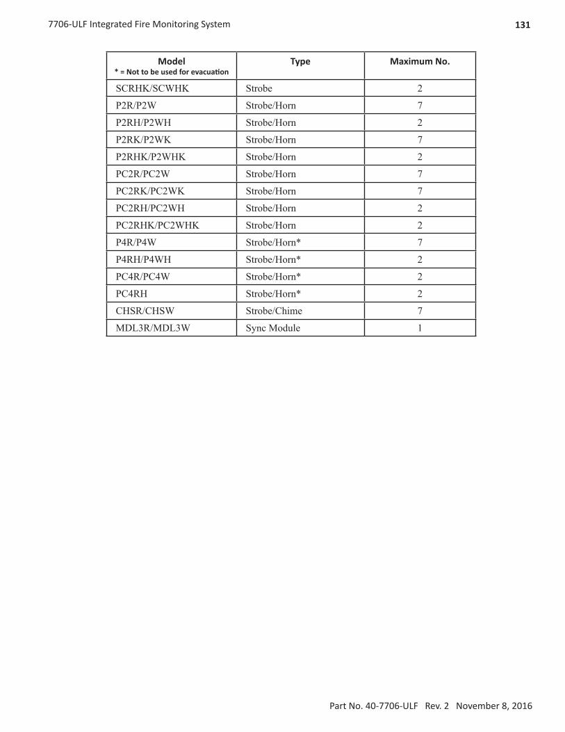
1317706-ULF Integrated Fire Monitoring System
Part No. 40-7706-ULF Rev. 2 November 8, 2016
Model* = Not to be used for evacuation
Type Maximum No.
SCRHK/SCWHK Strobe 2
P2R/P2W Strobe/Horn 7
P2RH/P2WH Strobe/Horn 2
P2RK/P2WK Strobe/Horn 7
P2RHK/P2WHK Strobe/Horn 2
PC2R/PC2W Strobe/Horn 7
PC2RK/PC2WK Strobe/Horn 7
PC2RH/PC2WH Strobe/Horn 2
PC2RHK/PC2WHK Strobe/Horn 2
P4R/P4W Strobe/Horn* 7
P4RH/P4WH Strobe/Horn* 2
PC4R/PC4W Strobe/Horn* 2
PC4RH Strobe/Horn* 2
CHSR/CHSW Strobe/Chime 7
MDL3R/MDL3W Sync Module 1

132 7706-ULF Integrated Fire Monitoring System
Part No. 40-7706-ULF Rev. 2 November 8, 2016
7706-ULF Integrated Fire Monitoring System
Operating Instructions
Normal Standby The green AC POWER LED will be illuminated, and the user-defined message on the LCD will be displayed. If the AC power is removed for more than 5 seconds, the green AC power LED will extinguish.
Acknowledging Off normal events are acknowledged by pressing the ACK key after scrolling down to new event. After all events have been acknowledged, the buzzer will deactivate and the associated LED will stop flashing and remain on continuously.
Alarm Condition The red ALARM LED will be flashing until it is acknowledged and will then display steady red anytime an alarm is occurring in the system. The LCD will display the number of inputs in alarm, and the buzzer will be activated. The buzzer will remain active until all alarms are acknowledged, or until the Silence key is pressed.
Silencing Alarm When the system is in Alarm, the notification circuits (strobes and horns) can be shut off by pushing the SILENCE key. The Silence LED will change status from flashing to steady. A programmable Automatic Silence will also shut off notification circuits. The Silence LED will remain flashing until the event is acknowledged.
Resetting Alarm After the condition that caused the alarm has been identified and corrected, the system may be reset to the Normal Standby by pressing the RESET key.
Supervisory Condition
When a supervisory condition is detected, the amber SUPERVISOR LED will illuminate and the buzzer will sound. The LCD display will indicate the number of supervisory events that are active. The local buzzer will sound until all supervisory events have been acknowledged.
Restoring Supervisory Condition
If the Supervisory condition is non-latching, once the device is restored to the normal condition, the supervisory event will clear. If the supervisory condition is latching, the device that was activated must be restored and the RESET key pressed.
Trouble Condition
When a fault condition occurs, the amber TROUBLE LED will illuminate and the local buzzer will sound until the fault is removed or the ACK key is pressed acknowledging the trouble condition. If the buzzer is acknowledged and the fault is not removed within 24 hours, the buzzer will resound.
Silencing Trouble(s)
When a trouble is occurring, the local buzzer will sound until either all troubles have been acknowledged or the SILENCE key is pressed.
Ground Fault When a conductor contacts an earth ground, the amber EARTH FAULT LED will illuminate and the LCD display will provide further information of where the fault is located.
Testing and Maintenance
Test this system monthly or more frequently as required by the AHJ. Before conducting any testing, contact the building personnel and the monitoring facility as applicable. When testing a system configured for releasing, activate the releasing disconnect switch to prevent accidental discharge of a suppression system. Test the circuits as outlined in the Installation Manual. Test in accordance with NFPA-72 and any local requirements. The batteries should be marked with the date of installation and replaced every four years or sooner if battery trouble occurs. Batteries should be checked with a tester acceptable to the AHJ such as a Stone Technologies model STC612A or equivalent. In case of a fuse replacement, refer to the Installation Manual for the proper rating. Contact the agency below for service or operational questions.
For service, contact:
Name: __________________________________________
Company: ______________________________________Address: ________________________________________
Telephone: ___________________________________
Frame and display instructions adjacent to the fire alarm panel. 40-7706-PI REV 1 7/14/2015