Embed Size (px)
Citation preview
6904 Parke East Blvd.Tampa, FL 33610-4115
MiTek USA, Inc. RE:
Design Code: FBC2017/TPI2014Wind Code: ASCE 7-10 Wind Speed: 150 mphRoof Load: 47.0 psf
Design Program: MiTek 20/20 8.4
1 of 2
This package includes 91 individual, dated Truss Design Drawings and 0 Additional Drawings.With my seal affixed to this sheet, I hereby certify that I am the Truss Design Engineer and this index sheetconforms to 61G15-31.003, section 5 of the Florida Board of Professional Engineers Rules.
General Truss Engineering Criteria & Design Loads (Individual Truss Design Drawings Show SpecialLoading Conditions):
Floor Load: 55.0 psf
September 25, 2020Velez, Joaquin
This item has been electronically signed and sealed by Velez, Joaquin using a Digital Signature.Printed copies of this document are not considered signed and sealed and the signature must be verified on any electronic copiesThe truss drawing(s) referenced above have been prepared by MiTek USA, Inc under my direct supervisionbased on the parameters provided by American Builders Supply, Inc..Truss Design Engineer's Name: Velez, JoaquinMy license renewal date for the state of Florida is February 28, 2021.
776860Tortola lot 202
IMPORTANT NOTE: The seal on these truss component designs is a certification that the engineer named is licensed in the jurisdiction(s) identified and that the designs comply with ANSI/TPI 1. These designs are based upon parameters shown (e.g., loads, supports, dimensions, shapes and design codes), which were given to MiTek. Any project specific information included is for MiTek customers file reference purpose only, and was not taken into account in the preparation of these designs. MiTek has not independently verified the applicability of the designparameters or the designs for any particular building. Before use, the building designer should verify applicability of design parameters and properly incorporate these designs into the overall building design per ANSI/TPI 1, Chapter 2.
Site Information:
Lot/Block: 202Customer: Taylor Morrison of Orlando Project Name: 776860
Subdivision: Lakeview PreserveAddress: 3367 Current AveState: FLCity: Winter Garden
Model: Tortola TR-A TRAYPKG EXP D
Florida COA: 6634
No. Seal# Truss Name Date1 T21407456 A01 9/25/20202 T21407457 A05 9/25/20203 T21407458 A06 9/25/20204 T21407459 A07 9/25/20205 T21407460 A08 9/25/20206 T21407461 A09 9/25/20207 T21407462 A09A 9/25/20208 T21407463 A10 9/25/20209 T21407464 A11 9/25/202010 T21407465 A12 9/25/202011 T21407466 A13 9/25/202012 T21407467 A14 9/25/202013 T21407468 A15 9/25/202014 T21407469 A16 9/25/202015 T21407470 A17 9/25/202016 T21407471 B01 9/25/202017 T21407472 B02 9/25/202018 T21407473 C01 9/25/202019 T21407474 CJ1 9/25/202020 T21407475 CJ1A 9/25/2020
No. Seal# Truss Name Date21 T21407476 CJ3 9/25/202022 T21407477 CJ3A 9/25/202023 T21407478 CJ3B 9/25/202024 T21407479 CJ3C 9/25/202025 T21407480 CJ3D 9/25/202026 T21407481 CJ3G 9/25/202027 T21407482 CJ5A 9/25/202028 T21407483 CJ5D 9/25/202029 T21407484 CJ5G 9/25/202030 T21407485 D01 9/25/202031 T21407486 E01 9/25/202032 T21407487 E02 9/25/202033 T21407488 E03 9/25/202034 T21407489 E04 9/25/202035 T21407490 E05 9/25/202036 T21407491 E06 9/25/202037 T21407492 E07 9/25/202038 T21407493 E08 9/25/202039 T21407494 E09 9/25/202040 T21407495 E10 9/25/2020
6904 Parke East Blvd.Tampa, FL 33610-4115
MiTek USA, Inc. RE: 776860 - Tortola lot 202
2 of 2
Site Information:
Lot/Block: 202Project Customer: Taylor Morrison of Orlando Project Name: 776860
Subdivision: Lakeview PreserveAddress: 3367 Current Ave
State: FLCity, County: Winter Garden
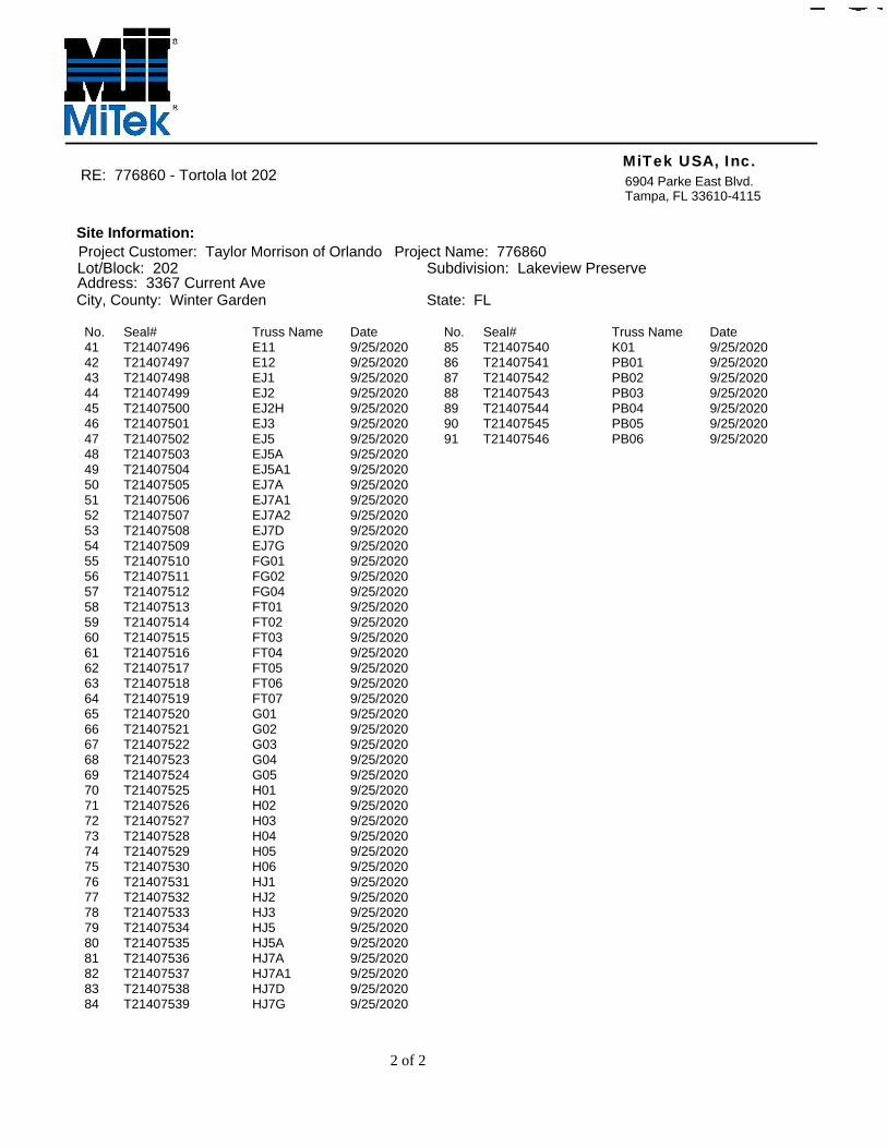
No. Seal# Truss Name Date41 T21407496 E11 9/25/202042 T21407497 E12 9/25/202043 T21407498 EJ1 9/25/202044 T21407499 EJ2 9/25/202045 T21407500 EJ2H 9/25/202046 T21407501 EJ3 9/25/202047 T21407502 EJ5 9/25/202048 T21407503 EJ5A 9/25/202049 T21407504 EJ5A1 9/25/202050 T21407505 EJ7A 9/25/202051 T21407506 EJ7A1 9/25/202052 T21407507 EJ7A2 9/25/202053 T21407508 EJ7D 9/25/202054 T21407509 EJ7G 9/25/202055 T21407510 FG01 9/25/202056 T21407511 FG02 9/25/202057 T21407512 FG04 9/25/202058 T21407513 FT01 9/25/202059 T21407514 FT02 9/25/202060 T21407515 FT03 9/25/202061 T21407516 FT04 9/25/202062 T21407517 FT05 9/25/202063 T21407518 FT06 9/25/202064 T21407519 FT07 9/25/202065 T21407520 G01 9/25/202066 T21407521 G02 9/25/202067 T21407522 G03 9/25/202068 T21407523 G04 9/25/202069 T21407524 G05 9/25/202070 T21407525 H01 9/25/202071 T21407526 H02 9/25/202072 T21407527 H03 9/25/202073 T21407528 H04 9/25/202074 T21407529 H05 9/25/202075 T21407530 H06 9/25/202076 T21407531 HJ1 9/25/202077 T21407532 HJ2 9/25/202078 T21407533 HJ3 9/25/202079 T21407534 HJ5 9/25/202080 T21407535 HJ5A 9/25/202081 T21407536 HJ7A 9/25/202082 T21407537 HJ7A1 9/25/202083 T21407538 HJ7D 9/25/202084 T21407539 HJ7G 9/25/2020
No. Seal# Truss Name Date85 T21407540 K01 9/25/202086 T21407541 PB01 9/25/202087 T21407542 PB02 9/25/202088 T21407543 PB03 9/25/202089 T21407544 PB04 9/25/202090 T21407545 PB05 9/25/202091 T21407546 PB06 9/25/2020
Design valid for use only with MiTek® connectors. This design is based only upon parameters shown, and is for an individual building component, not a truss system. Before use, the building designer must verify the applicability of design parameters and properly incorporate this design into the overall building design. Bracing indicated is to prevent buckling of individual truss web and/or chord members only. Additional temporary and permanent bracing is always required for stability and to prevent collapse with possible personal injury and property damage. For general guidance regarding the fabrication, storage, delivery, erection and bracing of trusses and truss systems, see ANSI/TPI1 Quality Criteria, DSB-89 and BCSI Building Component
available from Truss Plate Institute, 2670 Crain Highway, Suite 203 Waldorf, MD 20601Safety Information
WARNING - Verify design parameters and READ NOTES ON THIS AND INCLUDED MITEK REFERENCE PAGE MII-7473 rev. 5/19/2020 BEFORE USE.
6904 Parke East Blvd.Tampa, FL 36610
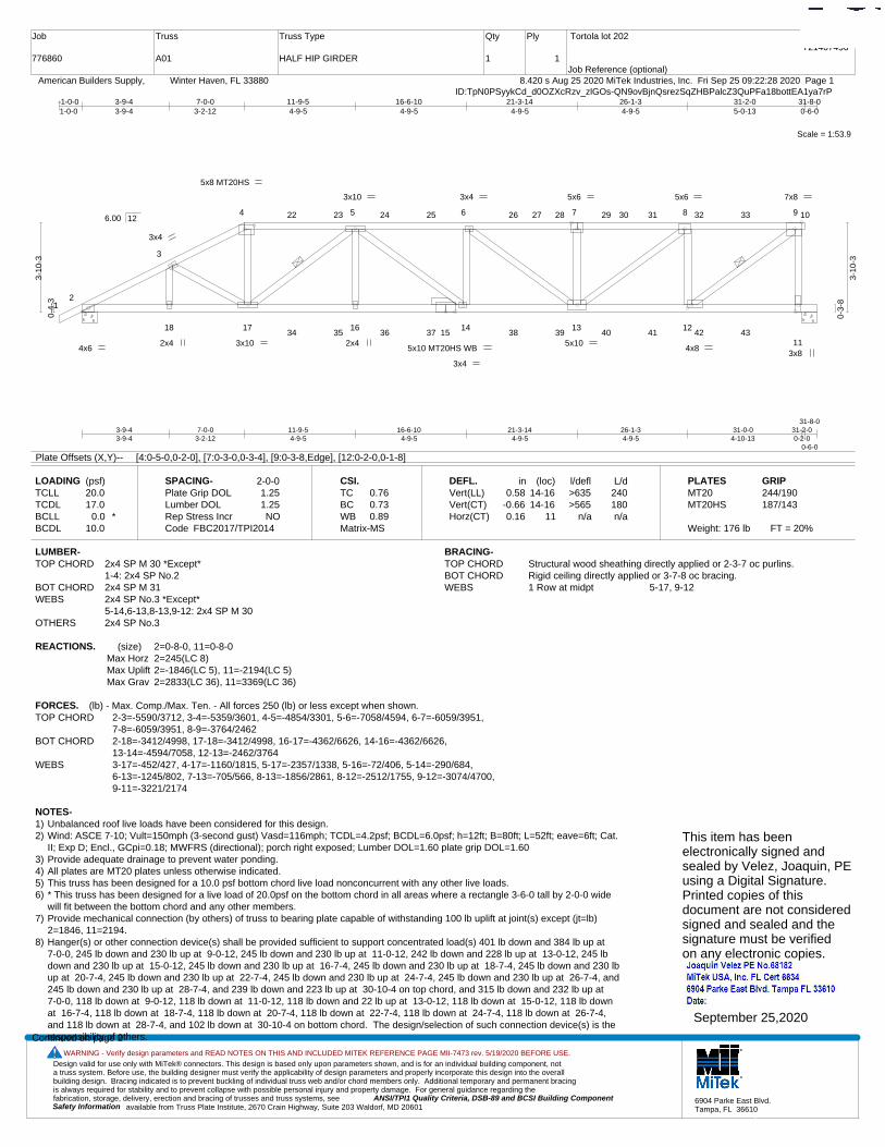
Job
776860
Truss
A01
Truss Type
HALF HIP GIRDER
Qty
1
Ply
1
Tortola lot 202
Job Reference (optional)
T21407456
8.420 s Aug 25 2020 MiTek Industries, Inc. Fri Sep 25 09:22:28 2020 Page 1 American Builders Supply, Winter Haven, FL 33880ID:TpN0PSyykCd_d0OZXcRzv_zlGOs-QN9ovBjnQsrezSqZHBPalcZ3QuPFa18bottEA1ya7rP
Scale = 1:53.9
12
3
4 5 6 7 8 9 10
18 17 1615
14 13 12
11
22 23 24 25 26 27 28 29 30 31 32 33
34 35 36 37 38 39 40 41 42 43
5x8 MT20HS
4x6 5x10 MT20HS WB
3x4
2x4 3x10
3x10
2x4
3x4
3x4 5x6
5x10
5x6
4x8
7x8
3x8
3-9-43-9-4
7-0-03-2-12
11-9-54-9-5
16-6-104-9-5
21-3-144-9-5
26-1-34-9-5
31-0-04-10-13
31-2-00-2-0
31-8-0
0-6-0
-1-0-01-0-0
3-9-43-9-4
7-0-03-2-12
11-9-54-9-5
16-6-104-9-5
21-3-144-9-5
26-1-34-9-5
31-2-05-0-13
31-8-00-6-0
0-4-
3
3-10
-3
0-3-
8
3-10
-3
6.00 12
Plate Offsets (X,Y)-- [4:0-5-0,0-2-0], [7:0-3-0,0-3-4], [9:0-3-8,Edge], [12:0-2-0,0-1-8]
LOADING (psf)TCLLTCDLBCLLBCDL
20.017.0
0.0 *10.0
SPACING-Plate Grip DOLLumber DOL Rep Stress IncrCode
2-0-01.251.25NO
FBC2017/TPI2014
CSI.TCBCWBMatrix-MS
0.760.730.89
DEFL.Vert(LL)Vert(CT)Horz(CT)
in0.58
-0.660.16
(loc)14-1614-16
11
l/defl>635>565
n/a
L/d240180n/a
PLATESMT20MT20HS
Weight: 176 lb FT = 20%
GRIP244/190187/143
LUMBER-TOP CHORD 2x4 SP M 30 *Except*
1-4: 2x4 SP No.2BOT CHORD 2x4 SP M 31WEBS 2x4 SP No.3 *Except*
5-14,6-13,8-13,9-12: 2x4 SP M 30OTHERS 2x4 SP No.3
BRACING-TOP CHORD Structural wood sheathing directly applied or 2-3-7 oc purlins.BOT CHORD Rigid ceiling directly applied or 3-7-8 oc bracing.WEBS 1 Row at midpt 5-17, 9-12
REACTIONS. (size) 2=0-8-0, 11=0-8-0Max Horz 2=245(LC 8)Max Uplift 2=-1846(LC 5), 11=-2194(LC 5)Max Grav 2=2833(LC 36), 11=3369(LC 36)
FORCES. (lb) - Max. Comp./Max. Ten. - All forces 250 (lb) or less except when shown.TOP CHORD 2-3=-5590/3712, 3-4=-5359/3601, 4-5=-4854/3301, 5-6=-7058/4594, 6-7=-6059/3951,
7-8=-6059/3951, 8-9=-3764/2462BOT CHORD 2-18=-3412/4998, 17-18=-3412/4998, 16-17=-4362/6626, 14-16=-4362/6626,
13-14=-4594/7058, 12-13=-2462/3764WEBS 3-17=-452/427, 4-17=-1160/1815, 5-17=-2357/1338, 5-16=-72/406, 5-14=-290/684,
6-13=-1245/802, 7-13=-705/566, 8-13=-1856/2861, 8-12=-2512/1755, 9-12=-3074/4700, 9-11=-3221/2174
NOTES-1) Unbalanced roof live loads have been considered for this design.2) Wind: ASCE 7-10; Vult=150mph (3-second gust) Vasd=116mph; TCDL=4.2psf; BCDL=6.0psf; h=12ft; B=80ft; L=52ft; eave=6ft; Cat.
II; Exp D; Encl., GCpi=0.18; MWFRS (directional); porch right exposed; Lumber DOL=1.60 plate grip DOL=1.603) Provide adequate drainage to prevent water ponding.4) All plates are MT20 plates unless otherwise indicated. 5) This truss has been designed for a 10.0 psf bottom chord live load nonconcurrent with any other live loads.6) * This truss has been designed for a live load of 20.0psf on the bottom chord in all areas where a rectangle 3-6-0 tall by 2-0-0 wide
will fit between the bottom chord and any other members.7) Provide mechanical connection (by others) of truss to bearing plate capable of withstanding 100 lb uplift at joint(s) except (jt=lb)
2=1846, 11=2194.8) Hanger(s) or other connection device(s) shall be provided sufficient to support concentrated load(s) 401 lb down and 384 lb up at
7-0-0, 245 lb down and 230 lb up at 9-0-12, 245 lb down and 230 lb up at 11-0-12, 242 lb down and 228 lb up at 13-0-12, 245 lbdown and 230 lb up at 15-0-12, 245 lb down and 230 lb up at 16-7-4, 245 lb down and 230 lb up at 18-7-4, 245 lb down and 230 lbup at 20-7-4, 245 lb down and 230 lb up at 22-7-4, 245 lb down and 230 lb up at 24-7-4, 245 lb down and 230 lb up at 26-7-4, and245 lb down and 230 lb up at 28-7-4, and 239 lb down and 223 lb up at 30-10-4 on top chord, and 315 lb down and 232 lb up at 7-0-0, 118 lb down at 9-0-12, 118 lb down at 11-0-12, 118 lb down and 22 lb up at 13-0-12, 118 lb down at 15-0-12, 118 lb downat 16-7-4, 118 lb down at 18-7-4, 118 lb down at 20-7-4, 118 lb down at 22-7-4, 118 lb down at 24-7-4, 118 lb down at 26-7-4,and 118 lb down at 28-7-4, and 102 lb down at 30-10-4 on bottom chord. The design/selection of such connection device(s) is theresponsibility of others.Continued on page 2
This item has beenelectronically signed andsealed by Velez, Joaquin, PEusing a Digital Signature.Printed copies of thisdocument are not consideredsigned and sealed and thesignature must be verified on any electronic copies.
September 25,2020
Design valid for use only with MiTek® connectors. This design is based only upon parameters shown, and is for an individual building component, not a truss system. Before use, the building designer must verify the applicability of design parameters and properly incorporate this design into the overall building design. Bracing indicated is to prevent buckling of individual truss web and/or chord members only. Additional temporary and permanent bracing is always required for stability and to prevent collapse with possible personal injury and property damage. For general guidance regarding the fabrication, storage, delivery, erection and bracing of trusses and truss systems, see ANSI/TPI1 Quality Criteria, DSB-89 and BCSI Building Component
available from Truss Plate Institute, 2670 Crain Highway, Suite 203 Waldorf, MD 20601Safety Information
WARNING - Verify design parameters and READ NOTES ON THIS AND INCLUDED MITEK REFERENCE PAGE MII-7473 rev. 5/19/2020 BEFORE USE.
6904 Parke East Blvd.Tampa, FL 36610
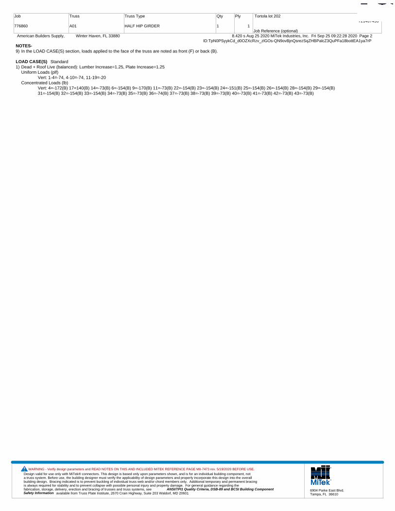
Job
776860
Truss
A01
Truss Type
HALF HIP GIRDER
Qty
1
Ply
1
Tortola lot 202
Job Reference (optional)
T21407456
8.420 s Aug 25 2020 MiTek Industries, Inc. Fri Sep 25 09:22:28 2020 Page 2 American Builders Supply, Winter Haven, FL 33880ID:TpN0PSyykCd_d0OZXcRzv_zlGOs-QN9ovBjnQsrezSqZHBPalcZ3QuPFa18bottEA1ya7rP
NOTES-9) In the LOAD CASE(S) section, loads applied to the face of the truss are noted as front (F) or back (B).
LOAD CASE(S) Standard1) Dead + Roof Live (balanced): Lumber Increase=1.25, Plate Increase=1.25
Uniform Loads (plf)Vert: 1-4=-74, 4-10=-74, 11-19=-20
Concentrated Loads (lb)Vert: 4=-172(B) 17=140(B) 14=-73(B) 6=-154(B) 9=-170(B) 11=-73(B) 22=-154(B) 23=-154(B) 24=-151(B) 25=-154(B) 26=-154(B) 28=-154(B) 29=-154(B)31=-154(B) 32=-154(B) 33=-154(B) 34=-73(B) 35=-73(B) 36=-74(B) 37=-73(B) 38=-73(B) 39=-73(B) 40=-73(B) 41=-73(B) 42=-73(B) 43=-73(B)
Design valid for use only with MiTek® connectors. This design is based only upon parameters shown, and is for an individual building component, not a truss system. Before use, the building designer must verify the applicability of design parameters and properly incorporate this design into the overall building design. Bracing indicated is to prevent buckling of individual truss web and/or chord members only. Additional temporary and permanent bracing is always required for stability and to prevent collapse with possible personal injury and property damage. For general guidance regarding the fabrication, storage, delivery, erection and bracing of trusses and truss systems, see ANSI/TPI1 Quality Criteria, DSB-89 and BCSI Building Component
available from Truss Plate Institute, 2670 Crain Highway, Suite 203 Waldorf, MD 20601Safety Information
WARNING - Verify design parameters and READ NOTES ON THIS AND INCLUDED MITEK REFERENCE PAGE MII-7473 rev. 5/19/2020 BEFORE USE.
6904 Parke East Blvd.Tampa, FL 36610
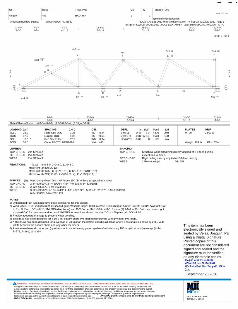
Job
776860
Truss
A05
Truss Type
HALF HIP
Qty
1
Ply
1
Tortola lot 202
Job Reference (optional)
T21407457
8.420 s Aug 25 2020 MiTek Industries, Inc. Fri Sep 25 09:22:29 2020 Page 1 American Builders Supply, Winter Haven, FL 33880ID:TpN0PSyykCd_d0OZXcRzv_zlGOs-uZjA7XkPBA_VabPlquwpIp6CzIiCJWjl0XdniTya7rO
Scale = 1:53.9
12
3
4 5 6 7
12 1110 9
8
16
17
18
4x8 5x6 3x4
6x6 4x4
4x4 3x4
2x4
6x6
4x4
3x4
9-0-09-0-0
13-0-04-0-0
21-10-48-10-4
31-0-09-1-12
31-8-00-8-0
-1-0-01-0-0
4-9-44-9-4
9-0-04-2-12
16-2-137-2-13
23-5-117-2-13
31-0-07-6-5
31-8-00-8-0
0-4-
3
4-10
-3
0-3-
8
4-10
-3
6.00 12
Plate Offsets (X,Y)-- [4:0-5-4,0-2-0], [6:0-3-0,0-3-4], [7:Edge,0-1-8]
LOADING (psf)TCLLTCDLBCLLBCDL
20.017.0
0.0 *10.0
SPACING-Plate Grip DOLLumber DOL Rep Stress IncrCode
2-0-01.251.25YES
FBC2017/TPI2014
CSI.TCBCWBMatrix-MS
0.840.940.74
DEFL.Vert(LL)Vert(CT)Horz(CT)
in0.45
-0.31-0.02
(loc)8-9
12-158
l/defl>479>503
n/a
L/d240180n/a
PLATESMT20
Weight: 163 lb FT = 20%
GRIP244/190
LUMBER-TOP CHORD 2x4 SP No.2BOT CHORD 2x4 SP No.2WEBS 2x4 SP No.3
BRACING-TOP CHORD Structural wood sheathing directly applied or 5-8-0 oc purlins,
except end verticals.BOT CHORD Rigid ceiling directly applied or 2-2-0 oc bracing.WEBS 1 Row at midpt 5-9, 6-8
REACTIONS. (size) 8=0-8-0, 2=0-8-0, 11=0-8-0Max Horz 2=330(LC 12)Max Uplift 8=-675(LC 9), 2=-161(LC 12), 11=-1364(LC 12)Max Grav 8=719(LC 22), 2=561(LC 17), 11=1790(LC 1)
FORCES. (lb) - Max. Comp./Max. Ten. - All forces 250 (lb) or less except when shown.TOP CHORD 2-3=-600/107, 3-4=-300/64, 4-5=-749/595, 5-6=-626/1025BOT CHORD 2-12=-439/577, 8-9=-1024/688WEBS 3-12=-490/673, 4-12=-144/411, 4-11=-961/901, 5-11=-1182/1575, 5-9=-1110/630,
6-9=-338/63, 6-8=-762/1124
NOTES-1) Unbalanced roof live loads have been considered for this design.2) Wind: ASCE 7-10; Vult=150mph (3-second gust) Vasd=116mph; TCDL=4.2psf; BCDL=6.0psf; h=25ft; B=78ft; L=50ft; eave=4ft; Cat.
II; Exp D; Encl., GCpi=0.18; MWFRS (directional) and C-C Corner(3) -1-0-0 to 4-0-0, Exterior(2) 4-0-0 to 30-10-4 zone; porch rightexposed;C-C for members and forces & MWFRS for reactions shown; Lumber DOL=1.60 plate grip DOL=1.60
3) Provide adequate drainage to prevent water ponding.4) This truss has been designed for a 10.0 psf bottom chord live load nonconcurrent with any other live loads.5) * This truss has been designed for a live load of 20.0psf on the bottom chord in all areas where a rectangle 3-6-0 tall by 2-0-0 wide
will fit between the bottom chord and any other members.6) Provide mechanical connection (by others) of truss to bearing plate capable of withstanding 100 lb uplift at joint(s) except (jt=lb)
8=675, 2=161, 11=1364.
This item has beenelectronically signed andsealed by Velez, Joaquin, PEusing a Digital Signature.Printed copies of thisdocument are not consideredsigned and sealed and thesignature must be verified on any electronic copies.
September 25,2020
Design valid for use only with MiTek® connectors. This design is based only upon parameters shown, and is for an individual building component, not a truss system. Before use, the building designer must verify the applicability of design parameters and properly incorporate this design into the overall building design. Bracing indicated is to prevent buckling of individual truss web and/or chord members only. Additional temporary and permanent bracing is always required for stability and to prevent collapse with possible personal injury and property damage. For general guidance regarding the fabrication, storage, delivery, erection and bracing of trusses and truss systems, see ANSI/TPI1 Quality Criteria, DSB-89 and BCSI Building Component
available from Truss Plate Institute, 2670 Crain Highway, Suite 203 Waldorf, MD 20601Safety Information
WARNING - Verify design parameters and READ NOTES ON THIS AND INCLUDED MITEK REFERENCE PAGE MII-7473 rev. 5/19/2020 BEFORE USE.
6904 Parke East Blvd.Tampa, FL 36610
Job
776860
Truss
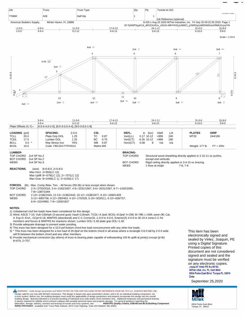
A06
Truss Type
Half Hip
Qty
1
Ply
1
Tortola lot 202
Job Reference (optional)
T21407458
8.420 s Aug 25 2020 MiTek Industries, Inc. Fri Sep 25 09:22:30 2020 Page 1 American Builders Supply, Winter Haven, FL 33880ID:TpN0PSyykCd_d0OZXcRzv_zlGOs-MlHYKtl1yU6MCl_yObR2q1eMDh692xtuFBMLEvya7rN
Scale = 1:53.9
12
3
4 5 6 7
13 1211
10 9 8
17
4x8 5x6 3x8
3x6 4x4
3x4
3x4
2x4 3x4
2x4
3x8 3x8
5-9-45-9-4
11-0-05-2-12
17-6-136-6-13
24-1-116-6-13
31-0-06-10-5
31-8-00-8-0
-1-0-01-0-0
5-9-45-9-4
11-0-05-2-12
17-6-136-6-13
24-1-116-6-13
31-0-06-10-5
31-8-00-8-0
0-4-
3
5-10
-3
0-3-
8
5-10
-3
6.00 12
Plate Offsets (X,Y)-- [4:0-5-4,0-2-0], [6:0-3-0,0-3-4], [9:0-3-8,0-1-8]
LOADING (psf)TCLLTCDLBCLLBCDL
20.017.0
0.0 *10.0
SPACING-Plate Grip DOLLumber DOL Rep Stress IncrCode
2-0-01.251.25YES
FBC2017/TPI2014
CSI.TCBCWBMatrix-MS
0.870.700.87
DEFL.Vert(LL)Vert(CT)Horz(CT)
in0.17
-0.260.08
(loc)10-1210-12
8
l/defl>999>999
n/a
L/d240180n/a
PLATESMT20
Weight: 177 lb FT = 20%
GRIP244/190
LUMBER-TOP CHORD 2x4 SP No.2BOT CHORD 2x4 SP No.2WEBS 2x4 SP No.3
BRACING-TOP CHORD Structural wood sheathing directly applied or 2-10-11 oc purlins,
except end verticals.BOT CHORD Rigid ceiling directly applied or 3-4-15 oc bracing.WEBS 1 Row at midpt 7-8, 7-9
REACTIONS. (size) 8=0-8-0, 2=0-8-0Max Horz 2=393(LC 12)Max Uplift 8=-679(LC 12), 2=-707(LC 12)Max Grav 8=1449(LC 1), 2=1526(LC 17)
FORCES. (lb) - Max. Comp./Max. Ten. - All forces 250 (lb) or less except when shown.TOP CHORD 2-3=-2753/2016, 3-4=-2182/1607, 4-5=-2031/1567, 5-6=-2031/1567, 6-7=-1432/1065,
7-8=-1387/1094BOT CHORD 2-13=-2196/2443, 12-13=-2196/2443, 10-12=-1538/1877, 9-10=-1090/1459WEBS 3-12=-690/758, 4-12=-280/463, 4-10=-170/328, 5-10=-503/511, 6-10=-630/757,
6-9=-1024/960, 7-9=-1359/1827
NOTES-1) Unbalanced roof live loads have been considered for this design.2) Wind: ASCE 7-10; Vult=150mph (3-second gust) Vasd=116mph; TCDL=4.2psf; BCDL=6.0psf; h=25ft; B=78ft; L=50ft; eave=3ft; Cat.
II; Exp D; Encl., GCpi=0.18; MWFRS (directional) and C-C Corner(3) -1-0-0 to 4-0-0, Exterior(2) 4-0-0 to 30-10-4 zone;C-C formembers and forces & MWFRS for reactions shown; Lumber DOL=1.60 plate grip DOL=1.60
3) Provide adequate drainage to prevent water ponding.4) This truss has been designed for a 10.0 psf bottom chord live load nonconcurrent with any other live loads.5) * This truss has been designed for a live load of 20.0psf on the bottom chord in all areas where a rectangle 3-6-0 tall by 2-0-0 wide
will fit between the bottom chord and any other members.6) Provide mechanical connection (by others) of truss to bearing plate capable of withstanding 100 lb uplift at joint(s) except (jt=lb)
8=679, 2=707.
This item has beenelectronically signed andsealed by Velez, Joaquin, PEusing a Digital Signature.Printed copies of thisdocument are not consideredsigned and sealed and thesignature must be verified on any electronic copies.
September 25,2020
Design valid for use only with MiTek® connectors. This design is based only upon parameters shown, and is for an individual building component, not a truss system. Before use, the building designer must verify the applicability of design parameters and properly incorporate this design into the overall building design. Bracing indicated is to prevent buckling of individual truss web and/or chord members only. Additional temporary and permanent bracing is always required for stability and to prevent collapse with possible personal injury and property damage. For general guidance regarding the fabrication, storage, delivery, erection and bracing of trusses and truss systems, see ANSI/TPI1 Quality Criteria, DSB-89 and BCSI Building Component
available from Truss Plate Institute, 2670 Crain Highway, Suite 203 Waldorf, MD 20601Safety Information
WARNING - Verify design parameters and READ NOTES ON THIS AND INCLUDED MITEK REFERENCE PAGE MII-7473 rev. 5/19/2020 BEFORE USE.
6904 Parke East Blvd.Tampa, FL 36610
Job
776860
Truss
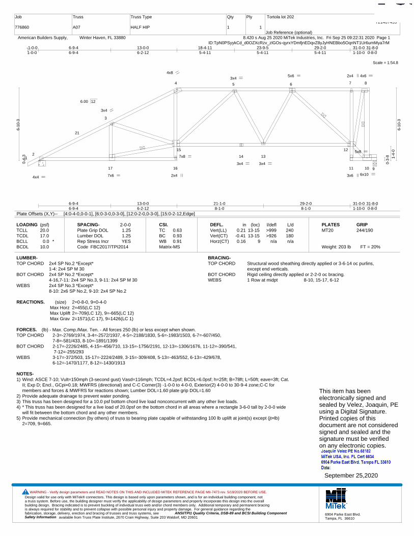
A07
Truss Type
HALF HIP
Qty
1
Ply
1
Tortola lot 202
Job Reference (optional)
T21407459
8.420 s Aug 25 2020 MiTek Industries, Inc. Fri Sep 25 09:22:31 2020 Page 1 American Builders Supply, Winter Haven, FL 33880ID:TpN0PSyykCd_d0OZXcRzv_zlGOs-qyrxYDmfjnEDqvZ8yJyHNEBbo5OqnNT1Ur6umMya7rM
Scale = 1:54.8
12
3
4 5 6 7 8
17 16
15
14 13
12
11 10 9
21
4x8 5x6 4x6
6x10 4x4 2x4
3x4
2x4
3x6
3x4
7x6
7x8
3x4
3x4
5x8
6-9-46-9-4
13-0-06-2-12
21-1-08-1-0
29-2-08-1-0
31-0-01-10-0
31-8-00-8-0
-1-0-01-0-0
6-9-46-9-4
13-0-06-2-12
18-4-115-4-11
23-9-55-4-11
29-2-05-4-11
31-0-01-10-0
31-8-00-8-0
0-4-
3
6-10
-3
0-3-
8 1-4-
0
6-10
-3
6.00 12
Plate Offsets (X,Y)-- [4:0-4-0,0-0-1], [6:0-3-0,0-3-0], [12:0-2-0,0-3-0], [15:0-2-12,Edge]
LOADING (psf)TCLLTCDLBCLLBCDL
20.017.0
0.0 *10.0
SPACING-Plate Grip DOLLumber DOL Rep Stress IncrCode
2-0-01.251.25YES
FBC2017/TPI2014
CSI.TCBCWBMatrix-MS
0.630.930.91
DEFL.Vert(LL)Vert(CT)Horz(CT)
in0.21
-0.410.16
(loc)13-1513-15
9
l/defl>999>926
n/a
L/d240180n/a
PLATESMT20
Weight: 203 lb FT = 20%
GRIP244/190
LUMBER-TOP CHORD 2x4 SP No.2 *Except*
1-4: 2x4 SP M 30BOT CHORD 2x4 SP No.2 *Except*
4-16,7-11: 2x4 SP No.3, 9-11: 2x4 SP M 30WEBS 2x4 SP No.3 *Except*
8-10: 2x6 SP No.2, 9-10: 2x4 SP No.2
BRACING-TOP CHORD Structural wood sheathing directly applied or 3-6-14 oc purlins,
except end verticals.BOT CHORD Rigid ceiling directly applied or 2-2-0 oc bracing.WEBS 1 Row at midpt 8-10, 15-17, 6-12
REACTIONS. (size) 2=0-8-0, 9=0-4-0Max Horz 2=455(LC 12)Max Uplift 2=-709(LC 12), 9=-665(LC 12)Max Grav 2=1571(LC 17), 9=1426(LC 1)
FORCES. (lb) - Max. Comp./Max. Ten. - All forces 250 (lb) or less except when shown.TOP CHORD 2-3=-2769/1974, 3-4=-2572/1937, 4-5=-2188/1830, 5-6=-1983/1503, 6-7=-607/450,
7-8=-581/433, 8-10=-1891/1399BOT CHORD 2-17=-2226/2485, 4-15=-456/710, 13-15=-1756/2191, 12-13=-1306/1676, 11-12=-390/541,
7-12=-255/293WEBS 3-17=-372/503, 15-17=-2224/2489, 3-15=-309/408, 5-13=-463/552, 6-13=-429/678,
6-12=-1470/1177, 8-12=-1430/1913
NOTES-1) Wind: ASCE 7-10; Vult=150mph (3-second gust) Vasd=116mph; TCDL=4.2psf; BCDL=6.0psf; h=25ft; B=78ft; L=50ft; eave=3ft; Cat.
II; Exp D; Encl., GCpi=0.18; MWFRS (directional) and C-C Corner(3) -1-0-0 to 4-0-0, Exterior(2) 4-0-0 to 30-9-4 zone;C-C formembers and forces & MWFRS for reactions shown; Lumber DOL=1.60 plate grip DOL=1.60
2) Provide adequate drainage to prevent water ponding.3) This truss has been designed for a 10.0 psf bottom chord live load nonconcurrent with any other live loads.4) * This truss has been designed for a live load of 20.0psf on the bottom chord in all areas where a rectangle 3-6-0 tall by 2-0-0 wide
will fit between the bottom chord and any other members.5) Provide mechanical connection (by others) of truss to bearing plate capable of withstanding 100 lb uplift at joint(s) except (jt=lb)
2=709, 9=665.
This item has beenelectronically signed andsealed by Velez, Joaquin, PEusing a Digital Signature.Printed copies of thisdocument are not consideredsigned and sealed and thesignature must be verified on any electronic copies.
September 25,2020
Design valid for use only with MiTek® connectors. This design is based only upon parameters shown, and is for an individual building component, not a truss system. Before use, the building designer must verify the applicability of design parameters and properly incorporate this design into the overall building design. Bracing indicated is to prevent buckling of individual truss web and/or chord members only. Additional temporary and permanent bracing is always required for stability and to prevent collapse with possible personal injury and property damage. For general guidance regarding the fabrication, storage, delivery, erection and bracing of trusses and truss systems, see ANSI/TPI1 Quality Criteria, DSB-89 and BCSI Building Component
available from Truss Plate Institute, 2670 Crain Highway, Suite 203 Waldorf, MD 20601Safety Information
WARNING - Verify design parameters and READ NOTES ON THIS AND INCLUDED MITEK REFERENCE PAGE MII-7473 rev. 5/19/2020 BEFORE USE.
6904 Parke East Blvd.Tampa, FL 36610
Job
776860
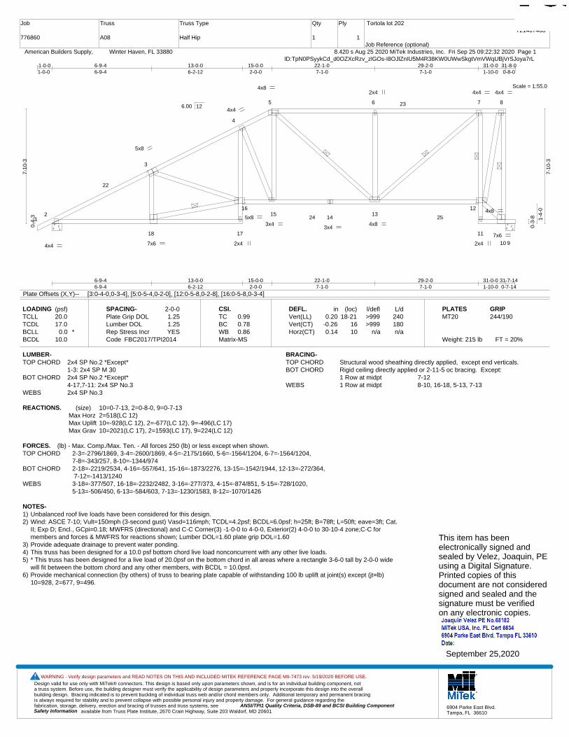
Truss
A08
Truss Type
Half Hip
Qty
1
Ply
1
Tortola lot 202
Job Reference (optional)
T21407460
8.420 s Aug 25 2020 MiTek Industries, Inc. Fri Sep 25 09:22:32 2020 Page 1 American Builders Supply, Winter Haven, FL 33880ID:TpN0PSyykCd_d0OZXcRzv_zlGOs-I8OJlZnIU5M4R38KW0UWwSkgtVmVWqUBjVrSJoya7rL
Scale = 1:55.0
12
3
4
5 6 7 8
18 17
1615
1413
12
11
10
22
23
24 25
9
5x8
4x8 4x4
7x6
4x4 2x4
4x4
3x4
4x4
2x4 7x6
5x8 3x4
2x4
4x8
4x8
6-9-46-9-4
13-0-06-2-12
15-0-02-0-0
22-1-07-1-0
29-2-07-1-0
31-0-01-10-0
31-7-140-7-14
-1-0-01-0-0
6-9-46-9-4
13-0-06-2-12
15-0-02-0-0
22-1-07-1-0
29-2-07-1-0
31-0-01-10-0
31-8-00-8-0
0-4-
3
7-10
-3
0-3-
8 1-4-
0
7-10
-3
6.00 12
Plate Offsets (X,Y)-- [3:0-4-0,0-3-4], [5:0-5-4,0-2-0], [12:0-5-8,0-2-8], [16:0-5-8,0-3-4]
LOADING (psf)TCLLTCDLBCLLBCDL
20.017.0
0.0 *10.0
SPACING-Plate Grip DOLLumber DOL Rep Stress IncrCode
2-0-01.251.25YES
FBC2017/TPI2014
CSI.TCBCWBMatrix-MS
0.990.780.86
DEFL.Vert(LL)Vert(CT)Horz(CT)
in0.20
-0.260.14
(loc)18-21
1610
l/defl>999>999
n/a
L/d240180n/a
PLATESMT20
Weight: 215 lb FT = 20%
GRIP244/190
LUMBER-TOP CHORD 2x4 SP No.2 *Except*
1-3: 2x4 SP M 30BOT CHORD 2x4 SP No.2 *Except*
4-17,7-11: 2x4 SP No.3WEBS 2x4 SP No.3
BRACING-TOP CHORD Structural wood sheathing directly applied, except end verticals.BOT CHORD Rigid ceiling directly applied or 2-11-5 oc bracing. Except:
1 Row at midpt 7-12WEBS 1 Row at midpt 8-10, 16-18, 5-13, 7-13
REACTIONS. (size) 10=0-7-13, 2=0-8-0, 9=0-7-13Max Horz 2=518(LC 12)Max Uplift 10=-928(LC 12), 2=-677(LC 12), 9=-496(LC 17)Max Grav 10=2021(LC 17), 2=1593(LC 17), 9=224(LC 12)
FORCES. (lb) - Max. Comp./Max. Ten. - All forces 250 (lb) or less except when shown.TOP CHORD 2-3=-2796/1869, 3-4=-2600/1869, 4-5=-2175/1660, 5-6=-1564/1204, 6-7=-1564/1204,
7-8=-343/257, 8-10=-1344/974BOT CHORD 2-18=-2219/2534, 4-16=-557/641, 15-16=-1873/2276, 13-15=-1542/1944, 12-13=-272/364,
7-12=-1413/1240WEBS 3-18=-377/507, 16-18=-2232/2482, 3-16=-277/373, 4-15=-874/851, 5-15=-728/1020,
5-13=-506/450, 6-13=-584/603, 7-13=-1230/1583, 8-12=-1070/1426
NOTES-1) Unbalanced roof live loads have been considered for this design.2) Wind: ASCE 7-10; Vult=150mph (3-second gust) Vasd=116mph; TCDL=4.2psf; BCDL=6.0psf; h=25ft; B=78ft; L=50ft; eave=3ft; Cat.
II; Exp D; Encl., GCpi=0.18; MWFRS (directional) and C-C Corner(3) -1-0-0 to 4-0-0, Exterior(2) 4-0-0 to 30-10-4 zone;C-C formembers and forces & MWFRS for reactions shown; Lumber DOL=1.60 plate grip DOL=1.60
3) Provide adequate drainage to prevent water ponding.4) This truss has been designed for a 10.0 psf bottom chord live load nonconcurrent with any other live loads.5) * This truss has been designed for a live load of 20.0psf on the bottom chord in all areas where a rectangle 3-6-0 tall by 2-0-0 wide
will fit between the bottom chord and any other members, with BCDL = 10.0psf.6) Provide mechanical connection (by others) of truss to bearing plate capable of withstanding 100 lb uplift at joint(s) except (jt=lb)
10=928, 2=677, 9=496.
This item has beenelectronically signed andsealed by Velez, Joaquin, PEusing a Digital Signature.Printed copies of thisdocument are not consideredsigned and sealed and thesignature must be verified on any electronic copies.
September 25,2020
Design valid for use only with MiTek® connectors. This design is based only upon parameters shown, and is for an individual building component, not a truss system. Before use, the building designer must verify the applicability of design parameters and properly incorporate this design into the overall building design. Bracing indicated is to prevent buckling of individual truss web and/or chord members only. Additional temporary and permanent bracing is always required for stability and to prevent collapse with possible personal injury and property damage. For general guidance regarding the fabrication, storage, delivery, erection and bracing of trusses and truss systems, see ANSI/TPI1 Quality Criteria, DSB-89 and BCSI Building Component
available from Truss Plate Institute, 2670 Crain Highway, Suite 203 Waldorf, MD 20601Safety Information
WARNING - Verify design parameters and READ NOTES ON THIS AND INCLUDED MITEK REFERENCE PAGE MII-7473 rev. 5/19/2020 BEFORE USE.
6904 Parke East Blvd.Tampa, FL 36610
Job
776860
Truss
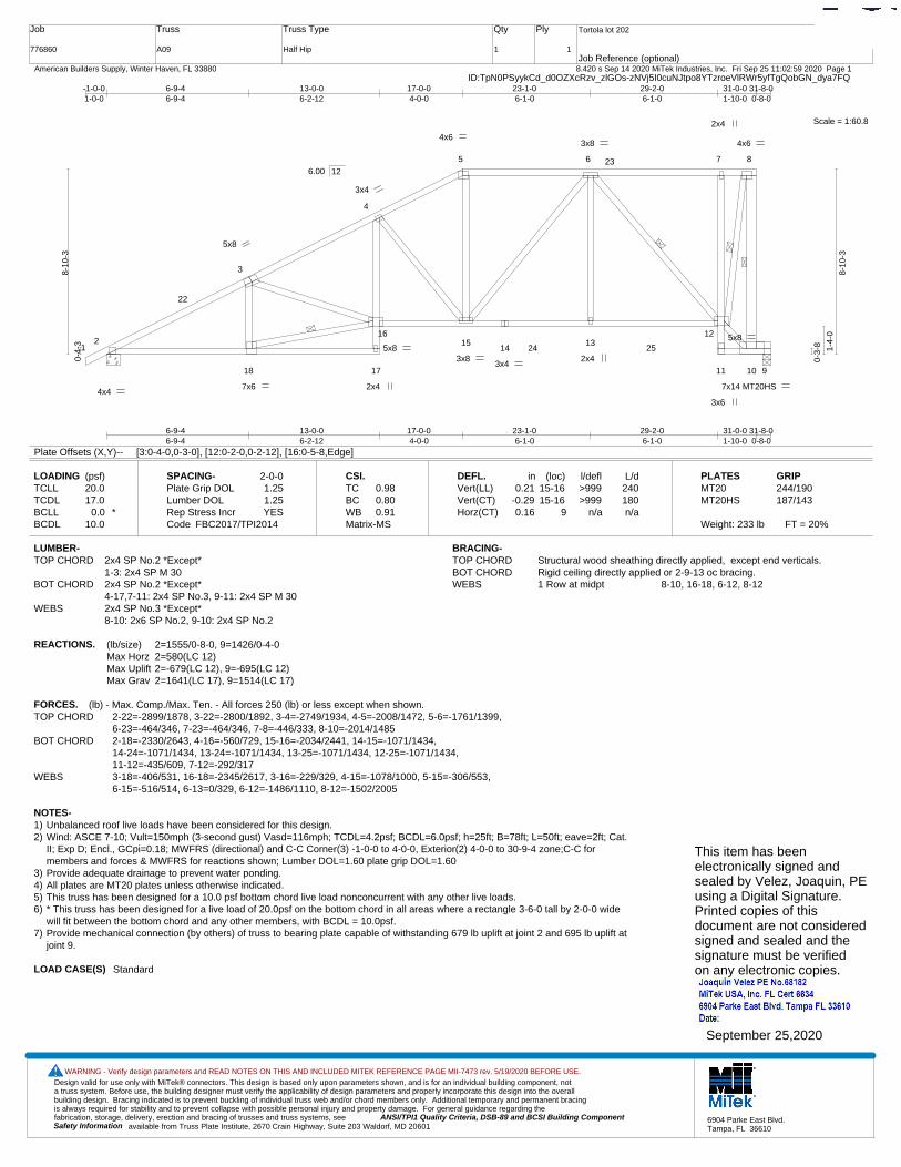
A09
Truss Type
Half Hip
Qty
1
Ply
1
Tortola lot 202
Job Reference (optional)
T21407461
8.420 s Sep 14 2020 MiTek Industries, Inc. Fri Sep 25 11:02:59 2020 Page 1 American Builders Supply, Winter Haven, FL 33880ID:TpN0PSyykCd_d0OZXcRzv_zlGOs-zNVj5I0cuNJtpo8YTzroeVlRWr5yfTgQobGN_dya7FQ
Scale = 1:60.8
12
3
4
5 6 7 8
18 17
1615
1413
12
11 10 9
22
23
24 25
5x8
4x6 4x6
7x14 MT20HS4x4
2x4
3x4
3x4
2x4
3x6
7x6
5x8 3x8 2x4
3x8
5x8
6-9-46-9-4
13-0-06-2-12
17-0-04-0-0
23-1-06-1-0
29-2-06-1-0
31-0-01-10-0
31-8-00-8-0
-1-0-01-0-0
6-9-46-9-4
13-0-06-2-12
17-0-04-0-0
23-1-06-1-0
29-2-06-1-0
31-0-01-10-0
31-8-00-8-0
0-4-
3
8-10
-3
0-3-
8 1-4-
0
8-10
-3
6.00 12
Plate Offsets (X,Y)-- [3:0-4-0,0-3-0], [12:0-2-0,0-2-12], [16:0-5-8,Edge]
LOADING (psf)TCLLTCDLBCLLBCDL
20.017.0
0.0 *10.0
SPACING-Plate Grip DOLLumber DOL Rep Stress IncrCode
2-0-01.251.25YES
FBC2017/TPI2014
CSI.TCBCWBMatrix-MS
0.980.800.91
DEFL.Vert(LL)Vert(CT)Horz(CT)
in0.21
-0.290.16
(loc)15-1615-16
9
l/defl>999>999
n/a
L/d240180n/a
PLATESMT20MT20HS
Weight: 233 lb FT = 20%
GRIP244/190187/143
LUMBER-TOP CHORD 2x4 SP No.2 *Except*
1-3: 2x4 SP M 30BOT CHORD 2x4 SP No.2 *Except*
4-17,7-11: 2x4 SP No.3, 9-11: 2x4 SP M 30WEBS 2x4 SP No.3 *Except*
8-10: 2x6 SP No.2, 9-10: 2x4 SP No.2
BRACING-TOP CHORD Structural wood sheathing directly applied, except end verticals.BOT CHORD Rigid ceiling directly applied or 2-9-13 oc bracing.WEBS 1 Row at midpt 8-10, 16-18, 6-12, 8-12
REACTIONS. (lb/size) 2=1555/0-8-0, 9=1426/0-4-0Max Horz 2=580(LC 12)Max Uplift 2=-679(LC 12), 9=-695(LC 12)Max Grav 2=1641(LC 17), 9=1514(LC 17)
FORCES. (lb) - Max. Comp./Max. Ten. - All forces 250 (lb) or less except when shown.TOP CHORD 2-22=-2899/1878, 3-22=-2800/1892, 3-4=-2749/1934, 4-5=-2008/1472, 5-6=-1761/1399,
6-23=-464/346, 7-23=-464/346, 7-8=-446/333, 8-10=-2014/1485BOT CHORD 2-18=-2330/2643, 4-16=-560/729, 15-16=-2034/2441, 14-15=-1071/1434,
14-24=-1071/1434, 13-24=-1071/1434, 13-25=-1071/1434, 12-25=-1071/1434, 11-12=-435/609, 7-12=-292/317
WEBS 3-18=-406/531, 16-18=-2345/2617, 3-16=-229/329, 4-15=-1078/1000, 5-15=-306/553, 6-15=-516/514, 6-13=0/329, 6-12=-1486/1110, 8-12=-1502/2005
NOTES-1) Unbalanced roof live loads have been considered for this design.2) Wind: ASCE 7-10; Vult=150mph (3-second gust) Vasd=116mph; TCDL=4.2psf; BCDL=6.0psf; h=25ft; B=78ft; L=50ft; eave=2ft; Cat.
II; Exp D; Encl., GCpi=0.18; MWFRS (directional) and C-C Corner(3) -1-0-0 to 4-0-0, Exterior(2) 4-0-0 to 30-9-4 zone;C-C formembers and forces & MWFRS for reactions shown; Lumber DOL=1.60 plate grip DOL=1.60
3) Provide adequate drainage to prevent water ponding.4) All plates are MT20 plates unless otherwise indicated. 5) This truss has been designed for a 10.0 psf bottom chord live load nonconcurrent with any other live loads.6) * This truss has been designed for a live load of 20.0psf on the bottom chord in all areas where a rectangle 3-6-0 tall by 2-0-0 wide
will fit between the bottom chord and any other members, with BCDL = 10.0psf.7) Provide mechanical connection (by others) of truss to bearing plate capable of withstanding 679 lb uplift at joint 2 and 695 lb uplift at
joint 9.
LOAD CASE(S) Standard
This item has beenelectronically signed andsealed by Velez, Joaquin, PEusing a Digital Signature.Printed copies of thisdocument are not consideredsigned and sealed and thesignature must be verified on any electronic copies.
September 25,2020
Design valid for use only with MiTek® connectors. This design is based only upon parameters shown, and is for an individual building component, not a truss system. Before use, the building designer must verify the applicability of design parameters and properly incorporate this design into the overall building design. Bracing indicated is to prevent buckling of individual truss web and/or chord members only. Additional temporary and permanent bracing is always required for stability and to prevent collapse with possible personal injury and property damage. For general guidance regarding the fabrication, storage, delivery, erection and bracing of trusses and truss systems, see ANSI/TPI1 Quality Criteria, DSB-89 and BCSI Building Component
available from Truss Plate Institute, 2670 Crain Highway, Suite 203 Waldorf, MD 20601Safety Information
WARNING - Verify design parameters and READ NOTES ON THIS AND INCLUDED MITEK REFERENCE PAGE MII-7473 rev. 5/19/2020 BEFORE USE.
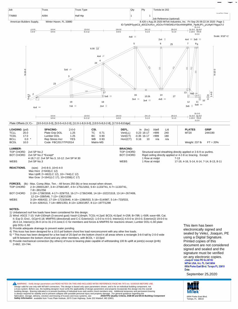
6904 Parke East Blvd.Tampa, FL 36610
Job
776860
Truss
A09A
Truss Type
Half Hip
Qty
1
Ply
1
Tortola lot 202
Job Reference (optional)
T21407462
8.420 s Aug 25 2020 MiTek Industries, Inc. Fri Sep 25 09:22:34 2020 Page 1 American Builders Supply, Winter Haven, FL 33880ID:TpN0PSyykCd_d0OZXcRzv_zlGOs-FXW3AEoY0icnhNHjdRW_?tp4kJP1_jzUApKYNgya7rJ
Scale: 3/16"=1'
12
3
4
5 6 7 8 9
19 18
1716
1514
13
12 11 10
23
24
25
26 27
5x6
4x4 2x4
4x4
3x4
4x4
3x6 7x6
5x8 3x4
4x8 2x4
4x8
5x8
4x8
3x8
6-9-46-9-4
13-0-06-2-12
19-0-06-0-0
24-1-05-1-0
29-2-05-1-0
31-0-01-10-0
31-2-0
0-2-0
31-8-00-6-0
-1-0-01-0-0
6-9-46-9-4
13-0-06-2-12
19-0-06-0-0
24-1-05-1-0
29-2-05-1-0
31-0-01-10-0
31-2-0
0-2-0
31-8-00-6-0
0-4-
3
9-10
-3
0-3-
8
1-4-
0
9-10
-3
6.00 12
Plate Offsets (X,Y)-- [3:0-3-0,0-3-0], [5:0-5-4,0-2-0], [11:0-1-8,0-3-0], [13:0-5-8,0-2-8], [17:0-5-8,Edge]
LOADING (psf)TCLLTCDLBCLLBCDL
20.017.0
0.0 *10.0
SPACING-Plate Grip DOLLumber DOL Rep Stress IncrCode
2-0-01.251.25YES
FBC2017/TPI2014
CSI.TCBCWBMatrix-MS
0.710.900.93
DEFL.Vert(LL)Vert(CT)Horz(CT)
in0.23
-0.350.16
(loc)16-1716-17
10
l/defl>999>999
n/a
L/d240180n/a
PLATESMT20
Weight: 237 lb FT = 20%
GRIP244/190
LUMBER-TOP CHORD 2x4 SP No.2BOT CHORD 2x4 SP No.2 *Except*
4-18,7-12: 2x4 SP No.3, 10-12: 2x4 SP M 30WEBS 2x4 SP No.3
BRACING-TOP CHORD Structural wood sheathing directly applied or 2-6-9 oc purlins.BOT CHORD Rigid ceiling directly applied or 4-2-8 oc bracing. Except:
1 Row at midpt 7-13WEBS 1 Row at midpt 17-19, 4-16, 5-14, 6-14, 7-14, 8-13, 8-11
REACTIONS. (size) 2=0-8-0, 10=0-4-0Max Horz 2=643(LC 12)Max Uplift 2=-662(LC 12), 10=-744(LC 12)Max Grav 2=1641(LC 17), 10=1558(LC 17)
FORCES. (lb) - Max. Comp./Max. Ten. - All forces 250 (lb) or less except when shown.TOP CHORD 2-3=-2900/1287, 3-4=-2768/1487, 4-5=-1751/1002, 5-6=-1133/741, 6-7=-1133/741,
7-8=-391/256BOT CHORD 2-19=-1738/2658, 4-17=-329/753, 16-17=-1736/2498, 14-16=-1022/1518, 13-14=-267/406,
12-13=-338/546, 7-13=-1362/1036WEBS 3-19=-406/432, 17-19=-1723/2640, 4-16=-1286/933, 5-16=-514/987, 5-14=-733/533,
6-14=-426/413, 7-14=-885/1353, 8-13=-1283/1957, 8-11=-1977/1298
NOTES-1) Unbalanced roof live loads have been considered for this design.2) Wind: ASCE 7-10; Vult=150mph (3-second gust) Vasd=116mph; TCDL=4.2psf; BCDL=6.0psf; h=25ft; B=78ft; L=50ft; eave=6ft; Cat.
II; Exp D; Encl., GCpi=0.18; MWFRS (directional) and C-C Exterior(2) -1-0-0 to 4-0-0, Interior(1) 4-0-0 to 19-0-0, Exterior(2) 19-0-0 to26-0-14, Interior(1) 26-0-14 to 31-2-0 zone;C-C for members and forces & MWFRS for reactions shown; Lumber DOL=1.60 plategrip DOL=1.60
3) Provide adequate drainage to prevent water ponding.4) This truss has been designed for a 10.0 psf bottom chord live load nonconcurrent with any other live loads.5) * This truss has been designed for a live load of 20.0psf on the bottom chord in all areas where a rectangle 3-6-0 tall by 2-0-0 wide
will fit between the bottom chord and any other members, with BCDL = 10.0psf.6) Provide mechanical connection (by others) of truss to bearing plate capable of withstanding 100 lb uplift at joint(s) except (jt=lb)
2=662, 10=744.
This item has beenelectronically signed andsealed by Velez, Joaquin, PEusing a Digital Signature.Printed copies of thisdocument are not consideredsigned and sealed and thesignature must be verified on any electronic copies.
September 25,2020
Design valid for use only with MiTek® connectors. This design is based only upon parameters shown, and is for an individual building component, not a truss system. Before use, the building designer must verify the applicability of design parameters and properly incorporate this design into the overall building design. Bracing indicated is to prevent buckling of individual truss web and/or chord members only. Additional temporary and permanent bracing is always required for stability and to prevent collapse with possible personal injury and property damage. For general guidance regarding the fabrication, storage, delivery, erection and bracing of trusses and truss systems, see ANSI/TPI1 Quality Criteria, DSB-89 and BCSI Building Component
available from Truss Plate Institute, 2670 Crain Highway, Suite 203 Waldorf, MD 20601Safety Information
WARNING - Verify design parameters and READ NOTES ON THIS AND INCLUDED MITEK REFERENCE PAGE MII-7473 rev. 5/19/2020 BEFORE USE.
6904 Parke East Blvd.Tampa, FL 36610
Job
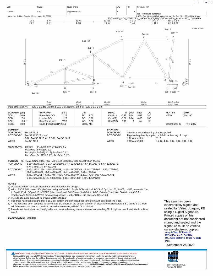
776860
Truss
A10
Truss Type
Piggyback Base
Qty
4
Ply
1
Tortola lot 202
Job Reference (optional)
T21407463
8.420 s Sep 14 2020 MiTek Industries, Inc. Fri Sep 25 11:03:53 2020 Page 1 American Builders Supply, Winter Haven, FL 33880ID:TpN0PSyykCd_d0OZXcRzv_zlGOs-Olm8QlgUAy7DI5GwdJpTqu_fgcV4JwcMD_LDtUya7Ea
Scale = 1:66.2
12
3
4
5 6 7 8
17 16
1514
13
12
11 10 9
21
22 23
6x6
4x6 3x8
4x4 2x4
4x4
3x4
2x4
3x6 5x6
4x10 3x8
3x4
4x12
6x12
6-9-46-9-4
13-0-06-2-12
19-3-116-3-11
29-2-09-10-5
31-0-01-10-0
31-8-00-8-0
-1-0-01-0-0
6-9-46-9-4
13-0-06-2-12
19-3-116-3-11
24-2-134-11-3
29-2-04-11-3
31-0-01-10-0
31-8-00-8-0
0-4-
3
10-0
-0
0-3-
8
1-4-
0
10-0
-0
6.00 12
Plate Offsets (X,Y)-- [3:0-3-0,Edge], [10:0-3-12,0-3-0], [12:0-5-4,0-2-0], [15:0-5-8,0-2-12]
LOADING (psf)TCLLTCDLBCLLBCDL
20.07.00.0 *
10.0
SPACING-Plate Grip DOLLumber DOL Rep Stress IncrCode
2-0-01.251.25YES
FBC2017/TPI2014
CSI.TCBCWBMatrix-MS
1.000.890.87
DEFL.Vert(LL)Vert(CT)Horz(CT)
in-0.35-0.620.13
(loc)12-1412-14
9
l/defl>999>605
n/a
L/d240180n/a
PLATESMT20
Weight: 226 lb FT = 20%
GRIP244/190
LUMBER-TOP CHORD 2x4 SP No.2BOT CHORD 2x4 SP M 30 *Except*
2-16: 2x4 SP No.2, 4-16,7-11: 2x4 SP No.3WEBS 2x4 SP No.3
BRACING-TOP CHORD Structural wood sheathing directly applied.BOT CHORD Rigid ceiling directly applied or 2-9-11 oc bracing. Except:
1 Row at midpt 7-12WEBS 1 Row at midpt 15-17, 4-14, 6-14, 6-12, 8-10, 8-12
REACTIONS. (lb/size) 2=1220/0-8-0, 9=1122/0-4-0Max Horz 2=609(LC 12)Max Uplift 2=-592(LC 12), 9=-644(LC 12)Max Grav 2=1327(LC 17), 9=1243(LC 17)
FORCES. (lb) - Max. Comp./Max. Ten. - All forces 250 (lb) or less except when shown.TOP CHORD 2-21=-2338/1676, 3-21=-2266/1690, 3-4=-2230/1750, 4-5=-1410/1079, 5-6=-1229/1079,
6-7=-338/271, 7-8=-322/261BOT CHORD 2-17=-2203/2194, 4-15=-505/598, 14-15=-1976/2049, 13-14=-795/867, 13-22=-795/867,
22-23=-795/867, 12-23=-795/867, 11-12=-498/596, 7-12=-182/261WEBS 3-17=-303/494, 15-17=-2201/2143, 3-15=-180/278, 4-14=-1045/1138, 5-14=-88/324,
6-14=-572/731, 6-12=-1020/1012, 8-10=-1795/1442, 8-12=-1457/1793
NOTES-1) Unbalanced roof live loads have been considered for this design.2) Wind: ASCE 7-10; Vult=150mph (3-second gust) Vasd=116mph; TCDL=4.2psf; BCDL=6.0psf; h=17ft; B=80ft; L=52ft; eave=4ft; Cat.
II; Exp D; Encl., GCpi=0.18; MWFRS (directional) and C-C Corner(3) -1-0-0 to 4-2-6, Exterior(2) 4-2-6 to 30-8-8 zone;C-C formembers and forces & MWFRS for reactions shown; Lumber DOL=1.60 plate grip DOL=1.60
3) Provide adequate drainage to prevent water ponding.4) This truss has been designed for a 10.0 psf bottom chord live load nonconcurrent with any other live loads.5) * This truss has been designed for a live load of 20.0psf on the bottom chord in all areas where a rectangle 3-6-0 tall by 2-0-0 wide
will fit between the bottom chord and any other members, with BCDL = 10.0psf.6) Provide mechanical connection (by others) of truss to bearing plate capable of withstanding 592 lb uplift at joint 2 and 644 lb uplift at
joint 9.
LOAD CASE(S) Standard
This item has beenelectronically signed andsealed by Velez, Joaquin, PEusing a Digital Signature.Printed copies of thisdocument are not consideredsigned and sealed and thesignature must be verified on any electronic copies.
September 25,2020
Design valid for use only with MiTek® connectors. This design is based only upon parameters shown, and is for an individual building component, not a truss system. Before use, the building designer must verify the applicability of design parameters and properly incorporate this design into the overall building design. Bracing indicated is to prevent buckling of individual truss web and/or chord members only. Additional temporary and permanent bracing is always required for stability and to prevent collapse with possible personal injury and property damage. For general guidance regarding the fabrication, storage, delivery, erection and bracing of trusses and truss systems, see ANSI/TPI1 Quality Criteria, DSB-89 and BCSI Building Component
available from Truss Plate Institute, 2670 Crain Highway, Suite 203 Waldorf, MD 20601Safety Information
WARNING - Verify design parameters and READ NOTES ON THIS AND INCLUDED MITEK REFERENCE PAGE MII-7473 rev. 5/19/2020 BEFORE USE.
6904 Parke East Blvd.Tampa, FL 36610
Job
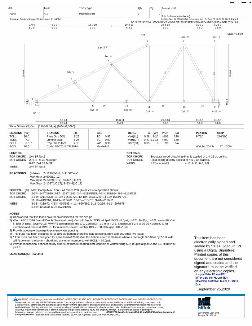
776860
Truss
A11
Truss Type
Piggyback Base
Qty
2
Ply
1
Tortola lot 202
Job Reference (optional)
T21407464
8.420 s Sep 14 2020 MiTek Industries, Inc. Fri Sep 25 11:04:26 2020 Page 1 American Builders Supply, Winter Haven, FL 33880ID:TpN0PSyykCd_d0OZXcRzv_zlGOs-w6FcM14BP5HXl9IG3kvCgrsIjvlJYpKDpdqTY4ya7E3
Scale = 1:60.9
12
3
4
5 6 7
13 1211 10 9 8
17
18 19 20
4x6 2x4
4x4 4x6 3x4
6x6
3x4
3x8 2x4 6x12
4x8
9-11-19-11-1
19-3-119-4-9
25-5-136-2-3
31-0-05-6-3
31-8-00-8-0
-1-0-01-0-0
6-9-96-9-9
13-0-106-3-1
19-3-116-3-1
25-5-136-2-3
31-0-05-6-3
31-8-00-8-0
0-4-
3
10-0
-0
0-3-
8
10-0
-0
6.00 12
Plate Offsets (X,Y)-- [3:0-3-0,Edge], [9:0-4-0,0-3-0]
LOADING (psf)TCLLTCDLBCLLBCDL
20.07.00.0 *
10.0
SPACING-Plate Grip DOLLumber DOL Rep Stress IncrCode
2-0-01.251.25YES
FBC2017/TPI2014
CSI.TCBCWBMatrix-MS
0.970.930.96
DEFL.Vert(LL)Vert(CT)Horz(CT)
in0.28
-0.470.05
(loc)9-10
11-138
l/defl>999>800
n/a
L/d240180n/a
PLATESMT20
Weight: 204 lb FT = 20%
GRIP244/190
LUMBER-TOP CHORD 2x4 SP No.2BOT CHORD 2x4 SP M 30 *Except*
8-12: 2x4 SP M 31WEBS 2x4 SP No.3
BRACING-TOP CHORD Structural wood sheathing directly applied or 1-4-12 oc purlins.BOT CHORD Rigid ceiling directly applied or 4-6-2 oc bracing.WEBS 1 Row at midpt 4-11, 6-11, 6-9, 7-9
REACTIONS. (lb/size) 2=1220/0-8-0, 8=1130/0-4-0Max Horz 2=609(LC 12)Max Uplift 2=-592(LC 12), 8=-651(LC 12)Max Grav 2=1397(LC 17), 8=1344(LC 17)
FORCES. (lb) - Max. Comp./Max. Ten. - All forces 250 (lb) or less except when shown.TOP CHORD 2-17=-2447/1680, 3-17=-2387/1693, 3-4=-2215/1525, 4-5=-1287/914, 5-6=-1119/928BOT CHORD 2-13=-2211/2308, 13-18=-1553/1720, 12-18=-1553/1720, 11-12=-1553/1720,
11-19=-613/761, 10-19=-613/761, 10-20=-613/761, 9-20=-613/761WEBS 3-13=-428/672, 4-13=-460/685, 4-11=-866/896, 5-11=0/255, 6-11=-597/678,
6-10=-129/500, 6-9=-1573/1266
NOTES-1) Unbalanced roof live loads have been considered for this design.2) Wind: ASCE 7-10; Vult=150mph (3-second gust) Vasd=116mph; TCDL=4.2psf; BCDL=6.0psf; h=17ft; B=80ft; L=52ft; eave=2ft; Cat.
II; Exp D; Encl., GCpi=0.18; MWFRS (directional) and C-C Corner(3) -1-0-0 to 4-2-6, Exterior(2) 4-2-6 to 30-10-4 zone;C-C formembers and forces & MWFRS for reactions shown; Lumber DOL=1.60 plate grip DOL=1.60
3) Provide adequate drainage to prevent water ponding.4) This truss has been designed for a 10.0 psf bottom chord live load nonconcurrent with any other live loads.5) * This truss has been designed for a live load of 20.0psf on the bottom chord in all areas where a rectangle 3-6-0 tall by 2-0-0 wide
will fit between the bottom chord and any other members, with BCDL = 10.0psf.6) Provide mechanical connection (by others) of truss to bearing plate capable of withstanding 592 lb uplift at joint 2 and 651 lb uplift at
joint 8.
LOAD CASE(S) Standard
This item has beenelectronically signed andsealed by Velez, Joaquin, PEusing a Digital Signature.Printed copies of thisdocument are not consideredsigned and sealed and thesignature must be verified on any electronic copies.
September 25,2020
Design valid for use only with MiTek® connectors. This design is based only upon parameters shown, and is for an individual building component, not a truss system. Before use, the building designer must verify the applicability of design parameters and properly incorporate this design into the overall building design. Bracing indicated is to prevent buckling of individual truss web and/or chord members only. Additional temporary and permanent bracing is always required for stability and to prevent collapse with possible personal injury and property damage. For general guidance regarding the fabrication, storage, delivery, erection and bracing of trusses and truss systems, see ANSI/TPI1 Quality Criteria, DSB-89 and BCSI Building Component
available from Truss Plate Institute, 2670 Crain Highway, Suite 203 Waldorf, MD 20601Safety Information
WARNING - Verify design parameters and READ NOTES ON THIS AND INCLUDED MITEK REFERENCE PAGE MII-7473 rev. 5/19/2020 BEFORE USE.
6904 Parke East Blvd.Tampa, FL 36610
Job
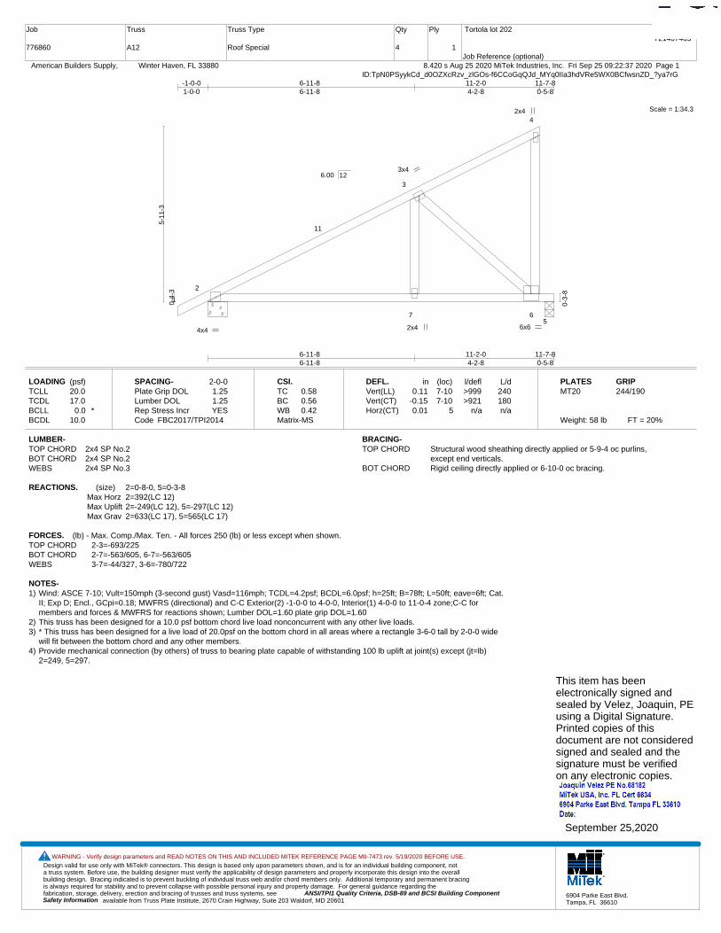
776860
Truss
A12
Truss Type
Roof Special
Qty
4
Ply
1
Tortola lot 202
Job Reference (optional)
T21407465
8.420 s Aug 25 2020 MiTek Industries, Inc. Fri Sep 25 09:22:37 2020 Page 1 American Builders Supply, Winter Haven, FL 33880ID:TpN0PSyykCd_d0OZXcRzv_zlGOs-f6CCoGqQJd_MYq0IIa3hdVRe5WX0BCfwsnZD_?ya7rG
Scale = 1:34.3
1
2
3
4
7 6
11
5
2x4
4x4
3x4
2x4 6x6
6-11-86-11-8
11-2-04-2-8
11-7-80-5-8
-1-0-01-0-0
6-11-86-11-8
11-2-04-2-8
11-7-80-5-8
0-4-
3
5-11
-3
0-3-
8
6.00 12
LOADING (psf)TCLLTCDLBCLLBCDL
20.017.0
0.0 *10.0
SPACING-Plate Grip DOLLumber DOL Rep Stress IncrCode
2-0-01.251.25YES
FBC2017/TPI2014
CSI.TCBCWBMatrix-MS
0.580.560.42
DEFL.Vert(LL)Vert(CT)Horz(CT)
in0.11
-0.150.01
(loc)7-107-10
5
l/defl>999>921
n/a
L/d240180n/a
PLATESMT20
Weight: 58 lb FT = 20%
GRIP244/190
LUMBER-TOP CHORD 2x4 SP No.2BOT CHORD 2x4 SP No.2WEBS 2x4 SP No.3
BRACING-TOP CHORD Structural wood sheathing directly applied or 5-9-4 oc purlins,
except end verticals.BOT CHORD Rigid ceiling directly applied or 6-10-0 oc bracing.
REACTIONS. (size) 2=0-8-0, 5=0-3-8Max Horz 2=392(LC 12)Max Uplift 2=-249(LC 12), 5=-297(LC 12)Max Grav 2=633(LC 17), 5=565(LC 17)
FORCES. (lb) - Max. Comp./Max. Ten. - All forces 250 (lb) or less except when shown.TOP CHORD 2-3=-693/225BOT CHORD 2-7=-563/605, 6-7=-563/605WEBS 3-7=-44/327, 3-6=-780/722
NOTES-1) Wind: ASCE 7-10; Vult=150mph (3-second gust) Vasd=116mph; TCDL=4.2psf; BCDL=6.0psf; h=25ft; B=78ft; L=50ft; eave=6ft; Cat.
II; Exp D; Encl., GCpi=0.18; MWFRS (directional) and C-C Exterior(2) -1-0-0 to 4-0-0, Interior(1) 4-0-0 to 11-0-4 zone;C-C formembers and forces & MWFRS for reactions shown; Lumber DOL=1.60 plate grip DOL=1.60
2) This truss has been designed for a 10.0 psf bottom chord live load nonconcurrent with any other live loads.3) * This truss has been designed for a live load of 20.0psf on the bottom chord in all areas where a rectangle 3-6-0 tall by 2-0-0 wide
will fit between the bottom chord and any other members.4) Provide mechanical connection (by others) of truss to bearing plate capable of withstanding 100 lb uplift at joint(s) except (jt=lb)
2=249, 5=297.
This item has beenelectronically signed andsealed by Velez, Joaquin, PEusing a Digital Signature.Printed copies of thisdocument are not consideredsigned and sealed and thesignature must be verified on any electronic copies.
September 25,2020
Design valid for use only with MiTek® connectors. This design is based only upon parameters shown, and is for an individual building component, not a truss system. Before use, the building designer must verify the applicability of design parameters and properly incorporate this design into the overall building design. Bracing indicated is to prevent buckling of individual truss web and/or chord members only. Additional temporary and permanent bracing is always required for stability and to prevent collapse with possible personal injury and property damage. For general guidance regarding the fabrication, storage, delivery, erection and bracing of trusses and truss systems, see ANSI/TPI1 Quality Criteria, DSB-89 and BCSI Building Component
available from Truss Plate Institute, 2670 Crain Highway, Suite 203 Waldorf, MD 20601Safety Information
WARNING - Verify design parameters and READ NOTES ON THIS AND INCLUDED MITEK REFERENCE PAGE MII-7473 rev. 5/19/2020 BEFORE USE.
6904 Parke East Blvd.Tampa, FL 36610
Job
776860
Truss
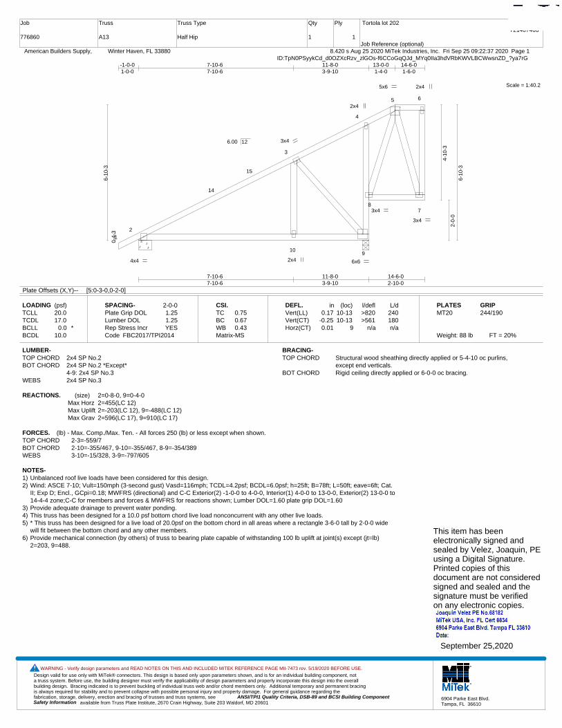
A13
Truss Type
Half Hip
Qty
1
Ply
1
Tortola lot 202
Job Reference (optional)
T21407466
8.420 s Aug 25 2020 MiTek Industries, Inc. Fri Sep 25 09:22:37 2020 Page 1 American Builders Supply, Winter Haven, FL 33880ID:TpN0PSyykCd_d0OZXcRzv_zlGOs-f6CCoGqQJd_MYq0IIa3hdVRbKWVLBCWwsnZD_?ya7rG
Scale = 1:40.2
12
3
4
5 6
109
87
14
15
2x4
3x4
4x4
2x4
3x4
3x4
2x4
5x6
6x6
7-10-67-10-6
11-8-03-9-10
14-6-02-10-0
-1-0-01-0-0
7-10-67-10-6
11-8-03-9-10
13-0-01-4-0
14-6-01-6-0
0-4-
3
6-10
-3
4-10
-3
2-0-
0
6-10
-3
6.00 12
Plate Offsets (X,Y)-- [5:0-3-0,0-2-0]
LOADING (psf)TCLLTCDLBCLLBCDL
20.017.0
0.0 *10.0
SPACING-Plate Grip DOLLumber DOL Rep Stress IncrCode
2-0-01.251.25YES
FBC2017/TPI2014
CSI.TCBCWBMatrix-MS
0.750.670.43
DEFL.Vert(LL)Vert(CT)Horz(CT)
in0.17
-0.250.01
(loc)10-1310-13
9
l/defl>820>561
n/a
L/d240180n/a
PLATESMT20
Weight: 88 lb FT = 20%
GRIP244/190
LUMBER-TOP CHORD 2x4 SP No.2BOT CHORD 2x4 SP No.2 *Except*
4-9: 2x4 SP No.3WEBS 2x4 SP No.3
BRACING-TOP CHORD Structural wood sheathing directly applied or 5-4-10 oc purlins,
except end verticals.BOT CHORD Rigid ceiling directly applied or 6-0-0 oc bracing.
REACTIONS. (size) 2=0-8-0, 9=0-4-0Max Horz 2=455(LC 12)Max Uplift 2=-203(LC 12), 9=-488(LC 12)Max Grav 2=596(LC 17), 9=910(LC 17)
FORCES. (lb) - Max. Comp./Max. Ten. - All forces 250 (lb) or less except when shown.TOP CHORD 2-3=-559/7BOT CHORD 2-10=-355/467, 9-10=-355/467, 8-9=-354/389WEBS 3-10=-15/328, 3-9=-797/605
NOTES-1) Unbalanced roof live loads have been considered for this design.2) Wind: ASCE 7-10; Vult=150mph (3-second gust) Vasd=116mph; TCDL=4.2psf; BCDL=6.0psf; h=25ft; B=78ft; L=50ft; eave=6ft; Cat.
II; Exp D; Encl., GCpi=0.18; MWFRS (directional) and C-C Exterior(2) -1-0-0 to 4-0-0, Interior(1) 4-0-0 to 13-0-0, Exterior(2) 13-0-0 to14-4-4 zone;C-C for members and forces & MWFRS for reactions shown; Lumber DOL=1.60 plate grip DOL=1.60
3) Provide adequate drainage to prevent water ponding.4) This truss has been designed for a 10.0 psf bottom chord live load nonconcurrent with any other live loads.5) * This truss has been designed for a live load of 20.0psf on the bottom chord in all areas where a rectangle 3-6-0 tall by 2-0-0 wide
will fit between the bottom chord and any other members.6) Provide mechanical connection (by others) of truss to bearing plate capable of withstanding 100 lb uplift at joint(s) except (jt=lb)
2=203, 9=488.
This item has beenelectronically signed andsealed by Velez, Joaquin, PEusing a Digital Signature.Printed copies of thisdocument are not consideredsigned and sealed and thesignature must be verified on any electronic copies.
September 25,2020
Design valid for use only with MiTek® connectors. This design is based only upon parameters shown, and is for an individual building component, not a truss system. Before use, the building designer must verify the applicability of design parameters and properly incorporate this design into the overall building design. Bracing indicated is to prevent buckling of individual truss web and/or chord members only. Additional temporary and permanent bracing is always required for stability and to prevent collapse with possible personal injury and property damage. For general guidance regarding the fabrication, storage, delivery, erection and bracing of trusses and truss systems, see ANSI/TPI1 Quality Criteria, DSB-89 and BCSI Building Component
available from Truss Plate Institute, 2670 Crain Highway, Suite 203 Waldorf, MD 20601Safety Information
WARNING - Verify design parameters and READ NOTES ON THIS AND INCLUDED MITEK REFERENCE PAGE MII-7473 rev. 5/19/2020 BEFORE USE.
6904 Parke East Blvd.Tampa, FL 36610
Job
776860
Truss
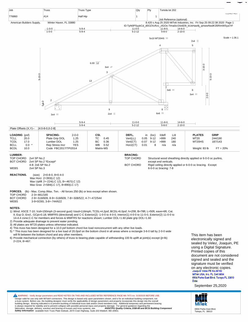
A14
Truss Type
Half Hip
Qty
1
Ply
1
Tortola lot 202
Job Reference (optional)
T21407467
8.420 s Aug 25 2020 MiTek Industries, Inc. Fri Sep 25 09:22:38 2020 Page 1 American Builders Supply, Winter Haven, FL 33880ID:TpN0PSyykCd_d0OZXcRzv_zlGOs-7Ima0cr24x6D9_bUsHaw9j_qmwwNwdK35RImWSya7rF
Scale = 1:36.1
1
2
3
4 5
9 8
76
13
2x4
3x4
3x4
3x6
3x4
2x4 6x6
5x10 MT20HS
5-9-45-9-4
11-0-05-2-12
11-8-00-8-0
14-6-02-10-0
-1-0-01-0-0
5-9-45-9-4
11-0-05-2-12
11-8-00-8-0
14-6-02-10-0
0-4-
3
5-10
-3
3-10
-3
2-0-
0
5-10
-3
6.00 12
Plate Offsets (X,Y)-- [4:0-8-0,0-2-8]
LOADING (psf)TCLLTCDLBCLLBCDL
20.017.0
0.0 *10.0
SPACING-Plate Grip DOLLumber DOL Rep Stress IncrCode
2-0-01.251.25YES
FBC2017/TPI2014
CSI.TCBCWBMatrix-MS
0.450.360.52
DEFL.Vert(LL)Vert(CT)Horz(CT)
in0.05
-0.070.01
(loc)9-129-12
8
l/defl>999>999
n/a
L/d240180n/a
PLATESMT20MT20HS
Weight: 83 lb FT = 20%
GRIP244/190187/143
LUMBER-TOP CHORD 2x4 SP No.2BOT CHORD 2x4 SP No.2 *Except*
4-8: 2x6 SP No.2WEBS 2x4 SP No.3
BRACING-TOP CHORD Structural wood sheathing directly applied or 6-0-0 oc purlins,
except end verticals.BOT CHORD Rigid ceiling directly applied or 6-0-0 oc bracing. Except:
6-0-0 oc bracing: 7-8
REACTIONS. (size) 2=0-8-0, 8=0-4-0Max Horz 2=393(LC 12)Max Uplift 2=-224(LC 12), 8=-467(LC 12)Max Grav 2=584(LC 17), 8=890(LC 17)
FORCES. (lb) - Max. Comp./Max. Ten. - All forces 250 (lb) or less except when shown.TOP CHORD 2-3=-661/165BOT CHORD 2-9=-518/609, 8-9=-518/609, 7-8=-508/522, 4-7=-472/544WEBS 3-9=0/265, 3-8=-744/622
NOTES-1) Wind: ASCE 7-10; Vult=150mph (3-second gust) Vasd=116mph; TCDL=4.2psf; BCDL=6.0psf; h=25ft; B=78ft; L=50ft; eave=6ft; Cat.
II; Exp D; Encl., GCpi=0.18; MWFRS (directional) and C-C Exterior(2) -1-0-0 to 4-0-0, Interior(1) 4-0-0 to 11-0-0, Exterior(2) 11-0-0 to14-4-4 zone;C-C for members and forces & MWFRS for reactions shown; Lumber DOL=1.60 plate grip DOL=1.60
2) Provide adequate drainage to prevent water ponding.3) All plates are MT20 plates unless otherwise indicated. 4) This truss has been designed for a 10.0 psf bottom chord live load nonconcurrent with any other live loads.5) * This truss has been designed for a live load of 20.0psf on the bottom chord in all areas where a rectangle 3-6-0 tall by 2-0-0 wide
will fit between the bottom chord and any other members.6) Provide mechanical connection (by others) of truss to bearing plate capable of withstanding 100 lb uplift at joint(s) except (jt=lb)
2=224, 8=467.
This item has beenelectronically signed andsealed by Velez, Joaquin, PEusing a Digital Signature.Printed copies of thisdocument are not consideredsigned and sealed and thesignature must be verified on any electronic copies.
September 25,2020
Design valid for use only with MiTek® connectors. This design is based only upon parameters shown, and is for an individual building component, not a truss system. Before use, the building designer must verify the applicability of design parameters and properly incorporate this design into the overall building design. Bracing indicated is to prevent buckling of individual truss web and/or chord members only. Additional temporary and permanent bracing is always required for stability and to prevent collapse with possible personal injury and property damage. For general guidance regarding the fabrication, storage, delivery, erection and bracing of trusses and truss systems, see ANSI/TPI1 Quality Criteria, DSB-89 and BCSI Building Component
available from Truss Plate Institute, 2670 Crain Highway, Suite 203 Waldorf, MD 20601Safety Information
WARNING - Verify design parameters and READ NOTES ON THIS AND INCLUDED MITEK REFERENCE PAGE MII-7473 rev. 5/19/2020 BEFORE USE.
6904 Parke East Blvd.Tampa, FL 36610
Job
776860
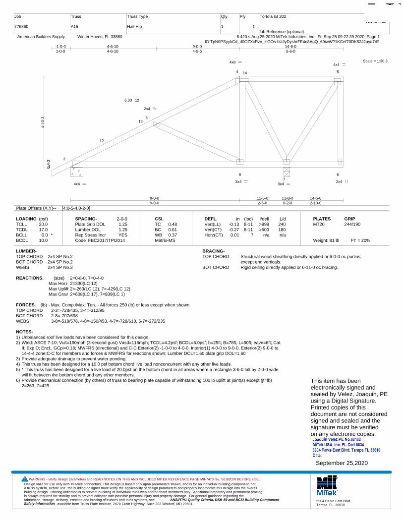
Truss
A15
Truss Type
Half Hip
Qty
1
Ply
1
Tortola lot 202
Job Reference (optional)
T21407468
8.420 s Aug 25 2020 MiTek Industries, Inc. Fri Sep 25 09:22:39 2020 Page 1 American Builders Supply, Winter Haven, FL 33880ID:TpN0PSyykCd_d0OZXcRzv_zlGOs-bUJyDyshrFE4n8AgQ_69iwW?1KCef70DK52J2uya7rE
Scale = 1:30.3
1
2
3
4 5
87
6
12
13
14
2x4 4x4
3x4
2x4
4x8
3x4
4x4
9-0-09-0-0
11-6-02-6-0
11-8-00-2-0
14-6-02-10-0
-1-0-01-0-0
4-6-104-6-10
9-0-04-5-6
14-6-05-6-0
0-4-
3
4-10
-3
6.00 12
Plate Offsets (X,Y)-- [4:0-5-4,0-2-0]
LOADING (psf)TCLLTCDLBCLLBCDL
20.017.0
0.0 *10.0
SPACING-Plate Grip DOLLumber DOL Rep Stress IncrCode
2-0-01.251.25YES
FBC2017/TPI2014
CSI.TCBCWBMatrix-MS
0.480.610.37
DEFL.Vert(LL)Vert(CT)Horz(CT)
in-0.13-0.270.01
(loc)8-118-11
7
l/defl>999>503
n/a
L/d240180n/a
PLATESMT20
Weight: 81 lb FT = 20%
GRIP244/190
LUMBER-TOP CHORD 2x4 SP No.2BOT CHORD 2x4 SP No.2WEBS 2x4 SP No.3
BRACING-TOP CHORD Structural wood sheathing directly applied or 6-0-0 oc purlins,
except end verticals.BOT CHORD Rigid ceiling directly applied or 6-11-0 oc bracing.
REACTIONS. (size) 2=0-8-0, 7=0-4-0Max Horz 2=330(LC 12)Max Uplift 2=-263(LC 12), 7=-429(LC 12)Max Grav 2=608(LC 17), 7=839(LC 1)
FORCES. (lb) - Max. Comp./Max. Ten. - All forces 250 (lb) or less except when shown.TOP CHORD 2-3=-728/435, 3-4=-312/95BOT CHORD 2-8=-707/698WEBS 3-8=-518/576, 4-8=-150/453, 4-7=-728/610, 5-7=-272/235
NOTES-1) Unbalanced roof live loads have been considered for this design.2) Wind: ASCE 7-10; Vult=150mph (3-second gust) Vasd=116mph; TCDL=4.2psf; BCDL=6.0psf; h=25ft; B=78ft; L=50ft; eave=6ft; Cat.
II; Exp D; Encl., GCpi=0.18; MWFRS (directional) and C-C Exterior(2) -1-0-0 to 4-0-0, Interior(1) 4-0-0 to 9-0-0, Exterior(2) 9-0-0 to14-4-4 zone;C-C for members and forces & MWFRS for reactions shown; Lumber DOL=1.60 plate grip DOL=1.60
3) Provide adequate drainage to prevent water ponding.4) This truss has been designed for a 10.0 psf bottom chord live load nonconcurrent with any other live loads.5) * This truss has been designed for a live load of 20.0psf on the bottom chord in all areas where a rectangle 3-6-0 tall by 2-0-0 wide
will fit between the bottom chord and any other members.6) Provide mechanical connection (by others) of truss to bearing plate capable of withstanding 100 lb uplift at joint(s) except (jt=lb)
2=263, 7=429.This item has beenelectronically signed andsealed by Velez, Joaquin, PEusing a Digital Signature.Printed copies of thisdocument are not consideredsigned and sealed and thesignature must be verified on any electronic copies.
September 25,2020
Design valid for use only with MiTek® connectors. This design is based only upon parameters shown, and is for an individual building component, not a truss system. Before use, the building designer must verify the applicability of design parameters and properly incorporate this design into the overall building design. Bracing indicated is to prevent buckling of individual truss web and/or chord members only. Additional temporary and permanent bracing is always required for stability and to prevent collapse with possible personal injury and property damage. For general guidance regarding the fabrication, storage, delivery, erection and bracing of trusses and truss systems, see ANSI/TPI1 Quality Criteria, DSB-89 and BCSI Building Component
available from Truss Plate Institute, 2670 Crain Highway, Suite 203 Waldorf, MD 20601Safety Information
WARNING - Verify design parameters and READ NOTES ON THIS AND INCLUDED MITEK REFERENCE PAGE MII-7473 rev. 5/19/2020 BEFORE USE.
6904 Parke East Blvd.Tampa, FL 36610
Job
776860
Truss
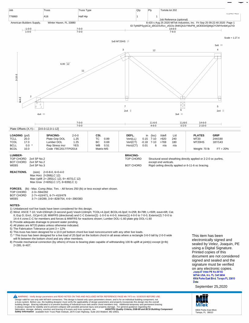
A16
Truss Type
Half Hip
Qty
1
Ply
1
Tortola lot 202
Job Reference (optional)
T21407469
8.420 s Aug 25 2020 MiTek Industries, Inc. Fri Sep 25 09:22:40 2020 Page 1 American Builders Supply, Winter Haven, FL 33880ID:TpN0PSyykCd_d0OZXcRzv_zlGOs-3htKQItJcYMxPIlt_idOE834SjWgOY2MYkntbKya7rD
Scale = 1:27.4
1
2
3 4
7
6
5
11
12
5x8 MT20HS
2x4
4x4
2x4
3x4
5x6
7-0-07-0-0
11-6-04-6-0
11-8-00-2-0
14-6-02-10-0
-1-0-01-0-0
7-0-07-0-0
14-6-07-6-0
0-4-
3
3-10
-3
6.00 12
Plate Offsets (X,Y)-- [3:0-3-12,0-1-12]
LOADING (psf)TCLLTCDLBCLLBCDL
20.017.0
0.0 *10.0
SPACING-Plate Grip DOLLumber DOL Rep Stress IncrCode
2-0-01.251.25YES
FBC2017/TPI2014
CSI.TCBCWBMatrix-MS
0.890.690.51
DEFL.Vert(LL)Vert(CT)Horz(CT)
in0.15
-0.180.01
(loc)7-107-10
6
l/defl>920>769
n/a
L/d240180n/a
PLATESMT20MT20HS
Weight: 70 lb FT = 20%
GRIP244/190187/143
LUMBER-TOP CHORD 2x4 SP No.2BOT CHORD 2x4 SP No.2WEBS 2x4 SP No.3
BRACING-TOP CHORD Structural wood sheathing directly applied or 2-2-0 oc purlins,
except end verticals.BOT CHORD Rigid ceiling directly applied or 6-11-6 oc bracing.
REACTIONS. (size) 2=0-8-0, 6=0-4-0Max Horz 2=268(LC 12)Max Uplift 2=-285(LC 12), 6=-407(LC 12)Max Grav 2=605(LC 17), 6=839(LC 1)
FORCES. (lb) - Max. Comp./Max. Ten. - All forces 250 (lb) or less except when shown.TOP CHORD 2-3=-594/292BOT CHORD 2-7=-410/471, 6-7=-410/479WEBS 3-7=-19/289, 3-6=-828/754, 4-6=-390/383
NOTES-1) Unbalanced roof live loads have been considered for this design.2) Wind: ASCE 7-10; Vult=150mph (3-second gust) Vasd=116mph; TCDL=4.2psf; BCDL=6.0psf; h=25ft; B=78ft; L=50ft; eave=6ft; Cat.
II; Exp D; Encl., GCpi=0.18; MWFRS (directional) and C-C Exterior(2) -1-0-0 to 4-0-0, Interior(1) 4-0-0 to 7-0-0, Exterior(2) 7-0-0 to14-4-4 zone;C-C for members and forces & MWFRS for reactions shown; Lumber DOL=1.60 plate grip DOL=1.60
3) Provide adequate drainage to prevent water ponding.4) All plates are MT20 plates unless otherwise indicated. 5) The Fabrication Tolerance at joint 3 = 12%6) This truss has been designed for a 10.0 psf bottom chord live load nonconcurrent with any other live loads.7) * This truss has been designed for a live load of 20.0psf on the bottom chord in all areas where a rectangle 3-6-0 tall by 2-0-0 wide
will fit between the bottom chord and any other members.8) Provide mechanical connection (by others) of truss to bearing plate capable of withstanding 100 lb uplift at joint(s) except (jt=lb)
2=285, 6=407.
This item has beenelectronically signed andsealed by Velez, Joaquin, PEusing a Digital Signature.Printed copies of thisdocument are not consideredsigned and sealed and thesignature must be verified on any electronic copies.
September 25,2020
Design valid for use only with MiTek® connectors. This design is based only upon parameters shown, and is for an individual building component, not a truss system. Before use, the building designer must verify the applicability of design parameters and properly incorporate this design into the overall building design. Bracing indicated is to prevent buckling of individual truss web and/or chord members only. Additional temporary and permanent bracing is always required for stability and to prevent collapse with possible personal injury and property damage. For general guidance regarding the fabrication, storage, delivery, erection and bracing of trusses and truss systems, see ANSI/TPI1 Quality Criteria, DSB-89 and BCSI Building Component
available from Truss Plate Institute, 2670 Crain Highway, Suite 203 Waldorf, MD 20601Safety Information
WARNING - Verify design parameters and READ NOTES ON THIS AND INCLUDED MITEK REFERENCE PAGE MII-7473 rev. 5/19/2020 BEFORE USE.
6904 Parke East Blvd.Tampa, FL 36610
Job
776860
Truss
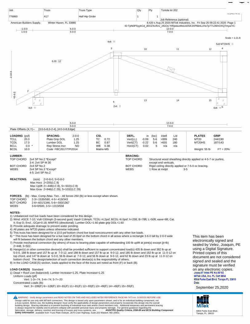
A17
Truss Type
Half Hip Girder
Qty
1
Ply
1
Tortola lot 202
Job Reference (optional)
T21407470
8.420 s Aug 25 2020 MiTek Industries, Inc. Fri Sep 25 09:22:41 2020 Page 1 American Builders Supply, Winter Haven, FL 33880ID:TpN0PSyykCd_d0OZXcRzv_zlGOs-YtRjeduxMsUo0SK3XP8dnLcHo7p771JWnOXQ7mya7rC
Scale = 1:21.8
1
2
3 4
6
5
10 11 12
13 14 15
4x8 5x8 MT20HS
4x4 2x4
6x6
5-0-05-0-0
12-0-07-0-0
-1-0-01-0-0
5-0-05-0-0
12-0-07-0-0
0-4-
3
2-10
-3
6.00 12
Plate Offsets (X,Y)-- [3:0-5-8,0-2-4], [4:0-3-8,Edge]
LOADING (psf)TCLLTCDLBCLLBCDL
20.017.0
0.0 *10.0
SPACING-Plate Grip DOLLumber DOL Rep Stress IncrCode
2-0-01.251.25NO
FBC2017/TPI2014
CSI.TCBCWBMatrix-MS
0.720.870.38
DEFL.Vert(LL)Vert(CT)Horz(CT)
in-0.09-0.220.02
(loc)5-65-6
5
l/defl>999>655
n/a
L/d240180n/a
PLATESMT20MT20HS
Weight: 55 lb FT = 20%
GRIP244/190187/143
LUMBER-TOP CHORD 2x4 SP No.2 *Except*
3-4: 2x4 SP M 30BOT CHORD 2x4 SP No.2WEBS 2x4 SP No.3 *Except*
4-5: 2x4 SP No.2
BRACING-TOP CHORD Structural wood sheathing directly applied or 4-5-7 oc purlins,
except end verticals.BOT CHORD Rigid ceiling directly applied or 7-5-0 oc bracing.WEBS 1 Row at midpt 3-5
REACTIONS. (size) 2=0-8-0, 5=0-8-0Max Horz 2=205(LC 8)Max Uplift 2=-448(LC 8), 5=-502(LC 8)Max Grav 2=946(LC 29), 5=1032(LC 29)
FORCES. (lb) - Max. Comp./Max. Ten. - All forces 250 (lb) or less except when shown.TOP CHORD 2-3=-1535/590, 4-5=-419/343BOT CHORD 2-6=-601/1346, 5-6=-593/1367WEBS 3-6=0/500, 3-5=-1313/558
NOTES-1) Unbalanced roof live loads have been considered for this design.2) Wind: ASCE 7-10; Vult=150mph (3-second gust) Vasd=116mph; TCDL=4.2psf; BCDL=6.0psf; h=25ft; B=78ft; L=50ft; eave=6ft; Cat.
II; Exp D; Encl., GCpi=0.18; MWFRS (directional); Lumber DOL=1.60 plate grip DOL=1.603) Provide adequate drainage to prevent water ponding.4) All plates are MT20 plates unless otherwise indicated. 5) This truss has been designed for a 10.0 psf bottom chord live load nonconcurrent with any other live loads.6) * This truss has been designed for a live load of 20.0psf on the bottom chord in all areas where a rectangle 3-6-0 tall by 2-0-0 wide
will fit between the bottom chord and any other members.7) Provide mechanical connection (by others) of truss to bearing plate capable of withstanding 100 lb uplift at joint(s) except (jt=lb)
2=448, 5=502.8) Hanger(s) or other connection device(s) shall be provided sufficient to support concentrated load(s) 435 lb down and 382 lb up at
5-0-0, 188 lb down and 157 lb up at 7-0-12, and 188 lb down and 157 lb up at 9-0-12, and 185 lb down and 162 lb up at 11-0-12 ontop chord, and 147 lb down at 5-0-0, 56 lb down at 7-0-12, and 56 lb down at 9-0-12, and 62 lb down and 23 lb up at 11-0-12 onbottom chord. The design/selection of such connection device(s) is the responsibility of others.
9) In the LOAD CASE(S) section, loads applied to the face of the truss are noted as front (F) or back (B).
LOAD CASE(S) Standard1) Dead + Roof Live (balanced): Lumber Increase=1.25, Plate Increase=1.25
Uniform Loads (plf)Vert: 1-3=-74, 3-4=-74, 5-7=-20
Concentrated Loads (lb)Vert: 3=-199(F) 6=-128(F) 10=-81(F) 11=-81(F) 12=-93(F) 13=-49(F) 14=-49(F) 15=-55(F)
This item has beenelectronically signed andsealed by Velez, Joaquin, PEusing a Digital Signature.Printed copies of thisdocument are not consideredsigned and sealed and thesignature must be verified on any electronic copies.
September 25,2020
Design valid for use only with MiTek® connectors. This design is based only upon parameters shown, and is for an individual building component, not a truss system. Before use, the building designer must verify the applicability of design parameters and properly incorporate this design into the overall building design. Bracing indicated is to prevent buckling of individual truss web and/or chord members only. Additional temporary and permanent bracing is always required for stability and to prevent collapse with possible personal injury and property damage. For general guidance regarding the fabrication, storage, delivery, erection and bracing of trusses and truss systems, see ANSI/TPI1 Quality Criteria, DSB-89 and BCSI Building Component
available from Truss Plate Institute, 2670 Crain Highway, Suite 203 Waldorf, MD 20601Safety Information
WARNING - Verify design parameters and READ NOTES ON THIS AND INCLUDED MITEK REFERENCE PAGE MII-7473 rev. 5/19/2020 BEFORE USE.
6904 Parke East Blvd.Tampa, FL 36610
Job
776860
Truss
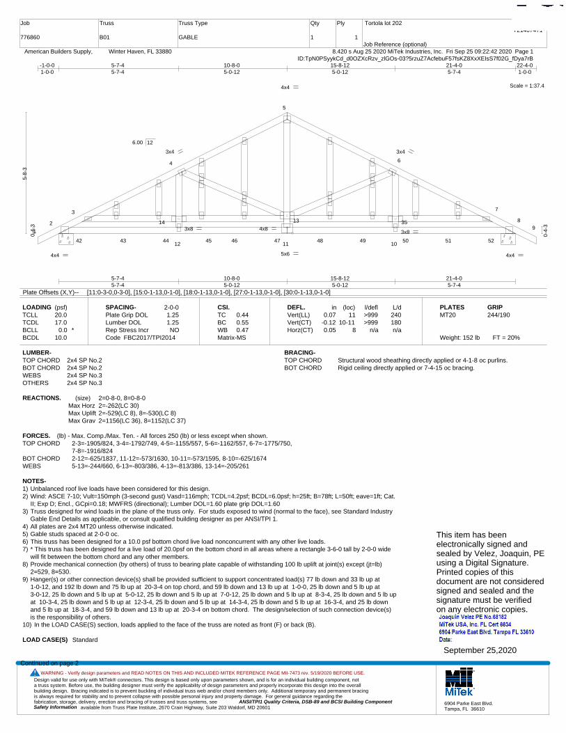
B01
Truss Type
GABLE
Qty
1
Ply
1
Tortola lot 202
Job Reference (optional)
T21407471
8.420 s Aug 25 2020 MiTek Industries, Inc. Fri Sep 25 09:22:42 2020 Page 1 American Builders Supply, Winter Haven, FL 33880ID:TpN0PSyykCd_d0OZXcRzv_zlGOs-03?5rzuZ7AcfebuF57fsKZ8XxXEIsS7f02G_fDya7rB
Scale = 1:37.4
1
2
3
4
5
6
7
89
12 11 10
13 3514
42 43 44 45 46 47 48 49 50 51 52
4x4
4x4 5x6
3x4
4x8
3x4
3x8
4x4
3x8
5-7-45-7-4
10-8-05-0-12
15-8-125-0-12
21-4-05-7-4
-1-0-01-0-0
5-7-45-7-4
10-8-05-0-12
15-8-125-0-12
21-4-05-7-4
22-4-01-0-0
0-4-
3
5-8-
3
0-4-
3
6.00 12
Plate Offsets (X,Y)-- [11:0-3-0,0-3-0], [15:0-1-13,0-1-0], [18:0-1-13,0-1-0], [27:0-1-13,0-1-0], [30:0-1-13,0-1-0]
LOADING (psf)TCLLTCDLBCLLBCDL
20.017.0
0.0 *10.0
SPACING-Plate Grip DOLLumber DOL Rep Stress IncrCode
2-0-01.251.25NO
FBC2017/TPI2014
CSI.TCBCWBMatrix-MS
0.440.550.47
DEFL.Vert(LL)Vert(CT)Horz(CT)
in0.07
-0.120.05
(loc)11
10-118
l/defl>999>999
n/a
L/d240180n/a
PLATESMT20
Weight: 152 lb FT = 20%
GRIP244/190
LUMBER-TOP CHORD 2x4 SP No.2BOT CHORD 2x4 SP No.2WEBS 2x4 SP No.3OTHERS 2x4 SP No.3
BRACING-TOP CHORD Structural wood sheathing directly applied or 4-1-8 oc purlins.BOT CHORD Rigid ceiling directly applied or 7-4-15 oc bracing.
REACTIONS. (size) 2=0-8-0, 8=0-8-0Max Horz 2=-262(LC 30)Max Uplift 2=-529(LC 8), 8=-530(LC 8)Max Grav 2=1156(LC 36), 8=1152(LC 37)
FORCES. (lb) - Max. Comp./Max. Ten. - All forces 250 (lb) or less except when shown.TOP CHORD 2-3=-1905/824, 3-4=-1792/749, 4-5=-1155/557, 5-6=-1162/557, 6-7=-1775/750,
7-8=-1916/824BOT CHORD 2-12=-625/1837, 11-12=-573/1630, 10-11=-573/1595, 8-10=-625/1674WEBS 5-13=-244/660, 6-13=-803/386, 4-13=-813/386, 13-14=-205/261
NOTES-1) Unbalanced roof live loads have been considered for this design.2) Wind: ASCE 7-10; Vult=150mph (3-second gust) Vasd=116mph; TCDL=4.2psf; BCDL=6.0psf; h=25ft; B=78ft; L=50ft; eave=1ft; Cat.
II; Exp D; Encl., GCpi=0.18; MWFRS (directional); Lumber DOL=1.60 plate grip DOL=1.603) Truss designed for wind loads in the plane of the truss only. For studs exposed to wind (normal to the face), see Standard Industry
Gable End Details as applicable, or consult qualified building designer as per ANSI/TPI 1.4) All plates are 2x4 MT20 unless otherwise indicated.5) Gable studs spaced at 2-0-0 oc.6) This truss has been designed for a 10.0 psf bottom chord live load nonconcurrent with any other live loads.7) * This truss has been designed for a live load of 20.0psf on the bottom chord in all areas where a rectangle 3-6-0 tall by 2-0-0 wide
will fit between the bottom chord and any other members.8) Provide mechanical connection (by others) of truss to bearing plate capable of withstanding 100 lb uplift at joint(s) except (jt=lb)
2=529, 8=530.9) Hanger(s) or other connection device(s) shall be provided sufficient to support concentrated load(s) 77 lb down and 33 lb up at
1-0-12, and 192 lb down and 75 lb up at 20-3-4 on top chord, and 59 lb down and 13 lb up at 1-0-0, 25 lb down and 5 lb up at 3-0-12, 25 lb down and 5 lb up at 5-0-12, 25 lb down and 5 lb up at 7-0-12, 25 lb down and 5 lb up at 8-3-4, 25 lb down and 5 lb upat 10-3-4, 25 lb down and 5 lb up at 12-3-4, 25 lb down and 5 lb up at 14-3-4, 25 lb down and 5 lb up at 16-3-4, and 25 lb downand 5 lb up at 18-3-4, and 59 lb down and 13 lb up at 20-3-4 on bottom chord. The design/selection of such connection device(s)is the responsibility of others.
10) In the LOAD CASE(S) section, loads applied to the face of the truss are noted as front (F) or back (B).
LOAD CASE(S) Standard
Continued on page 2
This item has beenelectronically signed andsealed by Velez, Joaquin, PEusing a Digital Signature.Printed copies of thisdocument are not consideredsigned and sealed and thesignature must be verified on any electronic copies.
September 25,2020
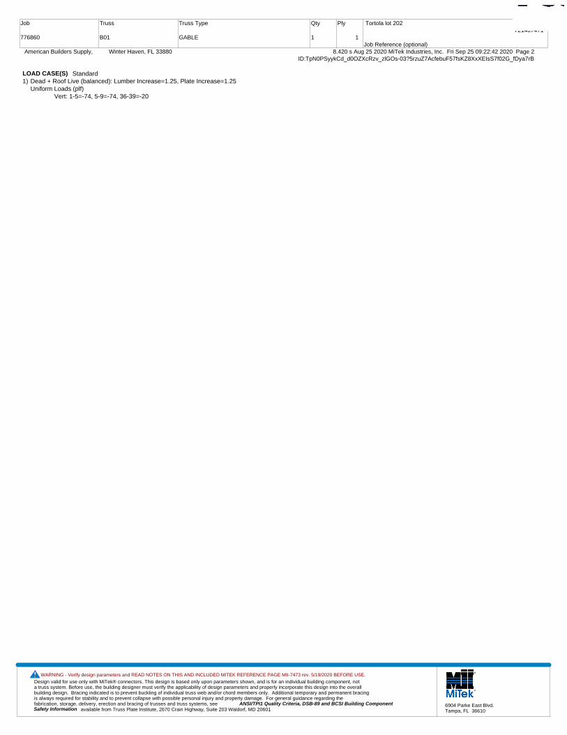
Design valid for use only with MiTek® connectors. This design is based only upon parameters shown, and is for an individual building component, not a truss system. Before use, the building designer must verify the applicability of design parameters and properly incorporate this design into the overall building design. Bracing indicated is to prevent buckling of individual truss web and/or chord members only. Additional temporary and permanent bracing is always required for stability and to prevent collapse with possible personal injury and property damage. For general guidance regarding the fabrication, storage, delivery, erection and bracing of trusses and truss systems, see ANSI/TPI1 Quality Criteria, DSB-89 and BCSI Building Component
available from Truss Plate Institute, 2670 Crain Highway, Suite 203 Waldorf, MD 20601Safety Information
WARNING - Verify design parameters and READ NOTES ON THIS AND INCLUDED MITEK REFERENCE PAGE MII-7473 rev. 5/19/2020 BEFORE USE.
6904 Parke East Blvd.Tampa, FL 36610
Job
776860
Truss
B01
Truss Type
GABLE
Qty
1
Ply
1
Tortola lot 202
Job Reference (optional)
T21407471
8.420 s Aug 25 2020 MiTek Industries, Inc. Fri Sep 25 09:22:42 2020 Page 2 American Builders Supply, Winter Haven, FL 33880ID:TpN0PSyykCd_d0OZXcRzv_zlGOs-03?5rzuZ7AcfebuF57fsKZ8XxXEIsS7f02G_fDya7rB
LOAD CASE(S) Standard1) Dead + Roof Live (balanced): Lumber Increase=1.25, Plate Increase=1.25
Uniform Loads (plf)Vert: 1-5=-74, 5-9=-74, 36-39=-20

Design valid for use only with MiTek® connectors. This design is based only upon parameters shown, and is for an individual building component, not a truss system. Before use, the building designer must verify the applicability of design parameters and properly incorporate this design into the overall building design. Bracing indicated is to prevent buckling of individual truss web and/or chord members only. Additional temporary and permanent bracing is always required for stability and to prevent collapse with possible personal injury and property damage. For general guidance regarding the fabrication, storage, delivery, erection and bracing of trusses and truss systems, see ANSI/TPI1 Quality Criteria, DSB-89 and BCSI Building Component
available from Truss Plate Institute, 2670 Crain Highway, Suite 203 Waldorf, MD 20601Safety Information
WARNING - Verify design parameters and READ NOTES ON THIS AND INCLUDED MITEK REFERENCE PAGE MII-7473 rev. 5/19/2020 BEFORE USE.
6904 Parke East Blvd.Tampa, FL 36610
Job
776860
Truss
B02
Truss Type
Common
Qty
4
Ply
1
Tortola lot 202
Job Reference (optional)
T21407472
8.420 s Aug 25 2020 MiTek Industries, Inc. Fri Sep 25 09:22:43 2020 Page 1 American Builders Supply, Winter Haven, FL 33880ID:TpN0PSyykCd_d0OZXcRzv_zlGOs-UFZT3JvBuTkWGlTSfqA5smhZVxYpbvHoFi0XBfya7rA
Scale = 1:38.6
1
2
3
4
5
67
8
15
16 17
18
4x4 5x10
4x4
2x4 2x4
4x4
10-8-010-8-0
21-4-010-8-0
-1-0-01-0-0
6-7-126-7-12
10-8-04-0-4
14-8-44-0-4
21-4-06-7-12
22-4-01-0-0
0-4-
3
5-8-
3
0-4-
3
6.00 12
Plate Offsets (X,Y)-- [8:0-5-0,0-3-0]
LOADING (psf)TCLLTCDLBCLLBCDL
20.017.0
0.0 *10.0
SPACING-Plate Grip DOLLumber DOL Rep Stress IncrCode
2-0-01.251.25YES
FBC2017/TPI2014
CSI.TCBCWBMatrix-MS
0.960.660.48
DEFL.Vert(LL)Vert(CT)Horz(CT)
in0.24
-0.440.03
(loc)8-118-14
6
l/defl>999>582
n/a
L/d240180n/a
PLATESMT20
Weight: 93 lb FT = 20%
GRIP244/190
LUMBER-TOP CHORD 2x4 SP No.2BOT CHORD 2x4 SP M 30WEBS 2x4 SP No.3
BRACING-TOP CHORD Structural wood sheathing directly applied or 2-2-0 oc purlins.BOT CHORD Rigid ceiling directly applied or 6-3-0 oc bracing.
REACTIONS. (size) 2=0-8-0, 6=0-8-0Max Horz 2=-262(LC 10)Max Uplift 2=-536(LC 12), 6=-536(LC 12)Max Grav 2=1077(LC 1), 6=1077(LC 1)
FORCES. (lb) - Max. Comp./Max. Ten. - All forces 250 (lb) or less except when shown.TOP CHORD 2-3=-1636/1656, 3-4=-1261/1381, 4-5=-1261/1381, 5-6=-1636/1656BOT CHORD 2-8=-1252/1471, 6-8=-1269/1410WEBS 4-8=-862/856, 5-8=-545/811, 3-8=-544/811
NOTES-1) Unbalanced roof live loads have been considered for this design.2) Wind: ASCE 7-10; Vult=150mph (3-second gust) Vasd=116mph; TCDL=4.2psf; BCDL=6.0psf; h=25ft; B=78ft; L=50ft; eave=1ft; Cat.
II; Exp D; Encl., GCpi=0.18; MWFRS (directional) and C-C Corner(3) -1-0-0 to 4-0-0, Exterior(2) 4-0-0 to 10-8-0, Corner(3) 10-8-0 to15-8-0, Exterior(2) 15-8-0 to 22-4-0 zone;C-C for members and forces & MWFRS for reactions shown; Lumber DOL=1.60 plate gripDOL=1.60
3) This truss has been designed for a 10.0 psf bottom chord live load nonconcurrent with any other live loads.4) * This truss has been designed for a live load of 20.0psf on the bottom chord in all areas where a rectangle 3-6-0 tall by 2-0-0 wide
will fit between the bottom chord and any other members.5) Provide mechanical connection (by others) of truss to bearing plate capable of withstanding 100 lb uplift at joint(s) except (jt=lb)
2=536, 6=536.This item has beenelectronically signed andsealed by Velez, Joaquin, PEusing a Digital Signature.Printed copies of thisdocument are not consideredsigned and sealed and thesignature must be verified on any electronic copies.
September 25,2020
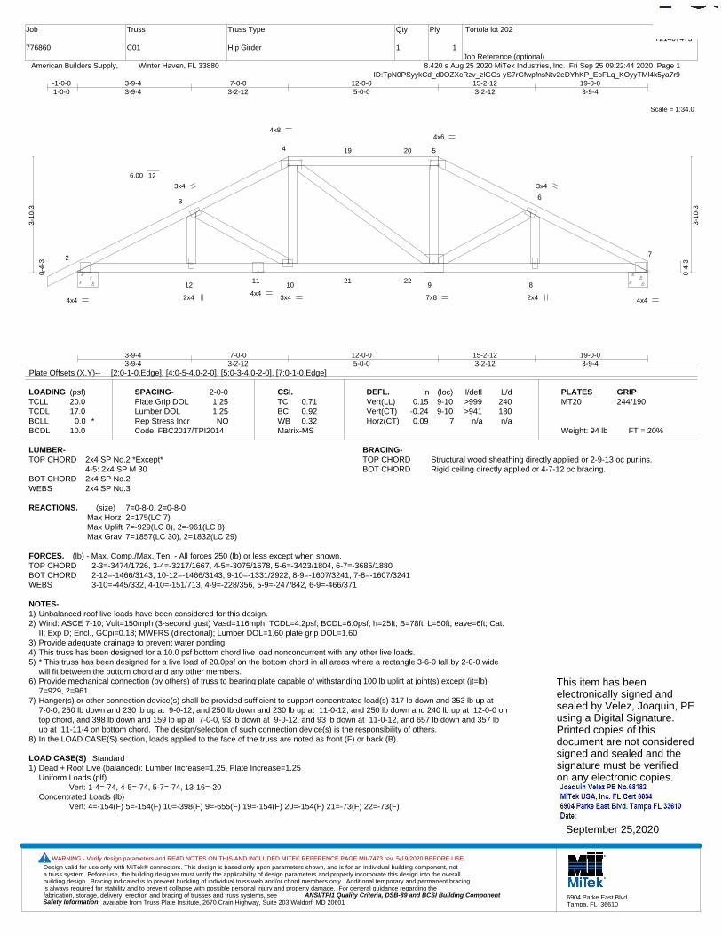
Design valid for use only with MiTek® connectors. This design is based only upon parameters shown, and is for an individual building component, not a truss system. Before use, the building designer must verify the applicability of design parameters and properly incorporate this design into the overall building design. Bracing indicated is to prevent buckling of individual truss web and/or chord members only. Additional temporary and permanent bracing is always required for stability and to prevent collapse with possible personal injury and property damage. For general guidance regarding the fabrication, storage, delivery, erection and bracing of trusses and truss systems, see ANSI/TPI1 Quality Criteria, DSB-89 and BCSI Building Component
available from Truss Plate Institute, 2670 Crain Highway, Suite 203 Waldorf, MD 20601Safety Information
WARNING - Verify design parameters and READ NOTES ON THIS AND INCLUDED MITEK REFERENCE PAGE MII-7473 rev. 5/19/2020 BEFORE USE.
6904 Parke East Blvd.Tampa, FL 36610
Job
776860
Truss
C01
Truss Type
Hip Girder
Qty
1
Ply
1
Tortola lot 202
Job Reference (optional)
T21407473
8.420 s Aug 25 2020 MiTek Industries, Inc. Fri Sep 25 09:22:44 2020 Page 1 American Builders Supply, Winter Haven, FL 33880ID:TpN0PSyykCd_d0OZXcRzv_zlGOs-yS7rGfwpfnsNtv2eDYhKP_EoFLq_KOyyTMl4k5ya7r9
Scale = 1:34.0
1
2
3
4 5
6
7
1211
10 9 8
19 20
21 22
4x8 4x6
4x4 4x4 4x4
3x4
2x4 3x4 7x8
3x4
2x4
3-9-43-9-4
7-0-03-2-12
12-0-05-0-0
15-2-123-2-12
19-0-03-9-4
-1-0-01-0-0
3-9-43-9-4
7-0-03-2-12
12-0-05-0-0
15-2-123-2-12
19-0-03-9-4
0-4-
3
3-10
-3
0-4-
3
3-10
-3
6.00 12
Plate Offsets (X,Y)-- [2:0-1-0,Edge], [4:0-5-4,0-2-0], [5:0-3-4,0-2-0], [7:0-1-0,Edge]
LOADING (psf)TCLLTCDLBCLLBCDL
20.017.0
0.0 *10.0
SPACING-Plate Grip DOLLumber DOL Rep Stress IncrCode
2-0-01.251.25NO
FBC2017/TPI2014
CSI.TCBCWBMatrix-MS
0.710.920.32
DEFL.Vert(LL)Vert(CT)Horz(CT)
in0.15
-0.240.09
(loc)9-109-10
7
l/defl>999>941
n/a
L/d240180n/a
PLATESMT20
Weight: 94 lb FT = 20%
GRIP244/190
LUMBER-TOP CHORD 2x4 SP No.2 *Except*
4-5: 2x4 SP M 30BOT CHORD 2x4 SP No.2WEBS 2x4 SP No.3
BRACING-TOP CHORD Structural wood sheathing directly applied or 2-9-13 oc purlins.BOT CHORD Rigid ceiling directly applied or 4-7-12 oc bracing.
REACTIONS. (size) 7=0-8-0, 2=0-8-0Max Horz 2=175(LC 7)Max Uplift 7=-929(LC 8), 2=-961(LC 8)Max Grav 7=1857(LC 30), 2=1832(LC 29)
FORCES. (lb) - Max. Comp./Max. Ten. - All forces 250 (lb) or less except when shown.TOP CHORD 2-3=-3474/1726, 3-4=-3217/1667, 4-5=-3075/1678, 5-6=-3423/1804, 6-7=-3685/1880BOT CHORD 2-12=-1466/3143, 10-12=-1466/3143, 9-10=-1331/2922, 8-9=-1607/3241, 7-8=-1607/3241WEBS 3-10=-445/332, 4-10=-151/713, 4-9=-228/356, 5-9=-247/842, 6-9=-466/371
NOTES-1) Unbalanced roof live loads have been considered for this design.2) Wind: ASCE 7-10; Vult=150mph (3-second gust) Vasd=116mph; TCDL=4.2psf; BCDL=6.0psf; h=25ft; B=78ft; L=50ft; eave=6ft; Cat.
II; Exp D; Encl., GCpi=0.18; MWFRS (directional); Lumber DOL=1.60 plate grip DOL=1.603) Provide adequate drainage to prevent water ponding.4) This truss has been designed for a 10.0 psf bottom chord live load nonconcurrent with any other live loads.5) * This truss has been designed for a live load of 20.0psf on the bottom chord in all areas where a rectangle 3-6-0 tall by 2-0-0 wide
will fit between the bottom chord and any other members.6) Provide mechanical connection (by others) of truss to bearing plate capable of withstanding 100 lb uplift at joint(s) except (jt=lb)
7=929, 2=961.7) Hanger(s) or other connection device(s) shall be provided sufficient to support concentrated load(s) 317 lb down and 353 lb up at
7-0-0, 250 lb down and 230 lb up at 9-0-12, and 250 lb down and 230 lb up at 11-0-12, and 250 lb down and 240 lb up at 12-0-0 ontop chord, and 398 lb down and 159 lb up at 7-0-0, 93 lb down at 9-0-12, and 93 lb down at 11-0-12, and 657 lb down and 357 lbup at 11-11-4 on bottom chord. The design/selection of such connection device(s) is the responsibility of others.
8) In the LOAD CASE(S) section, loads applied to the face of the truss are noted as front (F) or back (B).
LOAD CASE(S) Standard1) Dead + Roof Live (balanced): Lumber Increase=1.25, Plate Increase=1.25
Uniform Loads (plf)Vert: 1-4=-74, 4-5=-74, 5-7=-74, 13-16=-20
Concentrated Loads (lb)Vert: 4=-154(F) 5=-154(F) 10=-398(F) 9=-655(F) 19=-154(F) 20=-154(F) 21=-73(F) 22=-73(F)
This item has beenelectronically signed andsealed by Velez, Joaquin, PEusing a Digital Signature.Printed copies of thisdocument are not consideredsigned and sealed and thesignature must be verified on any electronic copies.
September 25,2020
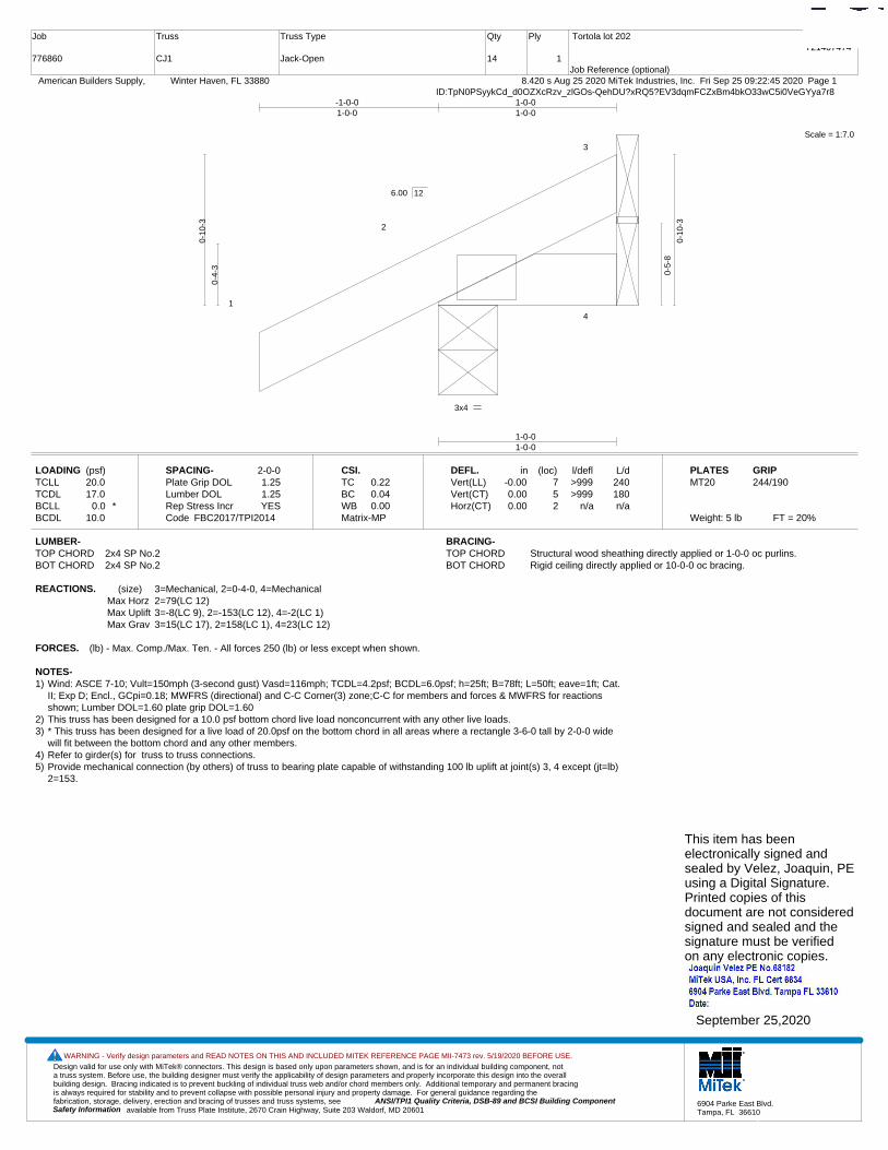
Design valid for use only with MiTek® connectors. This design is based only upon parameters shown, and is for an individual building component, not a truss system. Before use, the building designer must verify the applicability of design parameters and properly incorporate this design into the overall building design. Bracing indicated is to prevent buckling of individual truss web and/or chord members only. Additional temporary and permanent bracing is always required for stability and to prevent collapse with possible personal injury and property damage. For general guidance regarding the fabrication, storage, delivery, erection and bracing of trusses and truss systems, see ANSI/TPI1 Quality Criteria, DSB-89 and BCSI Building Component
available from Truss Plate Institute, 2670 Crain Highway, Suite 203 Waldorf, MD 20601Safety Information
WARNING - Verify design parameters and READ NOTES ON THIS AND INCLUDED MITEK REFERENCE PAGE MII-7473 rev. 5/19/2020 BEFORE USE.
6904 Parke East Blvd.Tampa, FL 36610
Job
776860
Truss
CJ1
Truss Type
Jack-Open
Qty
14
Ply
1
Tortola lot 202
Job Reference (optional)
T21407474
8.420 s Aug 25 2020 MiTek Industries, Inc. Fri Sep 25 09:22:45 2020 Page 1 American Builders Supply, Winter Haven, FL 33880ID:TpN0PSyykCd_d0OZXcRzv_zlGOs-QehDU?xRQ5?EV3dqmFCZxBm4bkO33wC5i0VeGYya7r8
Scale = 1:7.0
1
2
3
4
3x4
1-0-01-0-0
-1-0-01-0-0
1-0-01-0-0
0-4-
3
0-10
-3
0-5-
8
0-10
-3
6.00 12
LOADING (psf)TCLLTCDLBCLLBCDL
20.017.0
0.0 *10.0
SPACING-Plate Grip DOLLumber DOL Rep Stress IncrCode
2-0-01.251.25YES
FBC2017/TPI2014
CSI.TCBCWBMatrix-MP
0.220.040.00
DEFL.Vert(LL)Vert(CT)Horz(CT)
in-0.000.000.00
(loc)752
l/defl>999>999
n/a
L/d240180n/a
PLATESMT20
Weight: 5 lb FT = 20%
GRIP244/190
LUMBER-TOP CHORD 2x4 SP No.2BOT CHORD 2x4 SP No.2
BRACING-TOP CHORD Structural wood sheathing directly applied or 1-0-0 oc purlins.BOT CHORD Rigid ceiling directly applied or 10-0-0 oc bracing.
REACTIONS. (size) 3=Mechanical, 2=0-4-0, 4=MechanicalMax Horz 2=79(LC 12)Max Uplift 3=-8(LC 9), 2=-153(LC 12), 4=-2(LC 1)Max Grav 3=15(LC 17), 2=158(LC 1), 4=23(LC 12)
FORCES. (lb) - Max. Comp./Max. Ten. - All forces 250 (lb) or less except when shown.
NOTES-1) Wind: ASCE 7-10; Vult=150mph (3-second gust) Vasd=116mph; TCDL=4.2psf; BCDL=6.0psf; h=25ft; B=78ft; L=50ft; eave=1ft; Cat.
II; Exp D; Encl., GCpi=0.18; MWFRS (directional) and C-C Corner(3) zone;C-C for members and forces & MWFRS for reactionsshown; Lumber DOL=1.60 plate grip DOL=1.60
2) This truss has been designed for a 10.0 psf bottom chord live load nonconcurrent with any other live loads.3) * This truss has been designed for a live load of 20.0psf on the bottom chord in all areas where a rectangle 3-6-0 tall by 2-0-0 wide
will fit between the bottom chord and any other members.4) Refer to girder(s) for truss to truss connections.5) Provide mechanical connection (by others) of truss to bearing plate capable of withstanding 100 lb uplift at joint(s) 3, 4 except (jt=lb)
2=153.
This item has beenelectronically signed andsealed by Velez, Joaquin, PEusing a Digital Signature.Printed copies of thisdocument are not consideredsigned and sealed and thesignature must be verified on any electronic copies.
September 25,2020

Design valid for use only with MiTek® connectors. This design is based only upon parameters shown, and is for an individual building component, not a truss system. Before use, the building designer must verify the applicability of design parameters and properly incorporate this design into the overall building design. Bracing indicated is to prevent buckling of individual truss web and/or chord members only. Additional temporary and permanent bracing is always required for stability and to prevent collapse with possible personal injury and property damage. For general guidance regarding the fabrication, storage, delivery, erection and bracing of trusses and truss systems, see ANSI/TPI1 Quality Criteria, DSB-89 and BCSI Building Component
available from Truss Plate Institute, 2670 Crain Highway, Suite 203 Waldorf, MD 20601Safety Information
WARNING - Verify design parameters and READ NOTES ON THIS AND INCLUDED MITEK REFERENCE PAGE MII-7473 rev. 5/19/2020 BEFORE USE.
6904 Parke East Blvd.Tampa, FL 36610
Job
776860
Truss
CJ1A
Truss Type
Jack-Open
Qty
10
Ply
1
Tortola lot 202
Job Reference (optional)
T21407475
8.420 s Aug 25 2020 MiTek Industries, Inc. Fri Sep 25 09:22:46 2020 Page 1 American Builders Supply, Winter Haven, FL 33880ID:TpN0PSyykCd_d0OZXcRzv_zlGOs-uqFchLx4BO757DC1KzkoUPJFL8jIoNSFxgEBo_ya7r7
Scale = 1:7.0
1
2
3
4
3x4
1-0-01-0-0
-1-0-01-0-0
1-0-01-0-0
0-4-
3
0-10
-3
0-5-
8
0-10
-3
6.00 12
LOADING (psf)TCLLTCDLBCLLBCDL
20.017.0
0.0 *10.0
SPACING-Plate Grip DOLLumber DOL Rep Stress IncrCode
2-0-01.251.25YES
FBC2017/TPI2014
CSI.TCBCWBMatrix-MP
0.220.040.00
DEFL.Vert(LL)Vert(CT)Horz(CT)
in-0.000.000.00
(loc)752
l/defl>999>999
n/a
L/d240180n/a
PLATESMT20
Weight: 5 lb FT = 20%
GRIP244/190
LUMBER-TOP CHORD 2x4 SP No.2BOT CHORD 2x4 SP No.2
BRACING-TOP CHORD Structural wood sheathing directly applied or 1-0-0 oc purlins.BOT CHORD Rigid ceiling directly applied or 10-0-0 oc bracing.
REACTIONS. (size) 3=Mechanical, 2=0-8-0, 4=MechanicalMax Horz 2=79(LC 12)Max Uplift 3=-8(LC 9), 2=-153(LC 12), 4=-2(LC 1)Max Grav 3=15(LC 17), 2=158(LC 1), 4=23(LC 12)
FORCES. (lb) - Max. Comp./Max. Ten. - All forces 250 (lb) or less except when shown.
NOTES-1) Wind: ASCE 7-10; Vult=150mph (3-second gust) Vasd=116mph; TCDL=4.2psf; BCDL=6.0psf; h=25ft; B=78ft; L=50ft; eave=1ft; Cat.
II; Exp D; Encl., GCpi=0.18; MWFRS (directional) and C-C Corner(3) zone; porch right exposed;C-C for members and forces &MWFRS for reactions shown; Lumber DOL=1.60 plate grip DOL=1.60
2) This truss has been designed for a 10.0 psf bottom chord live load nonconcurrent with any other live loads.3) * This truss has been designed for a live load of 20.0psf on the bottom chord in all areas where a rectangle 3-6-0 tall by 2-0-0 wide
will fit between the bottom chord and any other members.4) Refer to girder(s) for truss to truss connections.5) Provide mechanical connection (by others) of truss to bearing plate capable of withstanding 100 lb uplift at joint(s) 3, 4 except (jt=lb)
2=153.
This item has beenelectronically signed andsealed by Velez, Joaquin, PEusing a Digital Signature.Printed copies of thisdocument are not consideredsigned and sealed and thesignature must be verified on any electronic copies.
September 25,2020
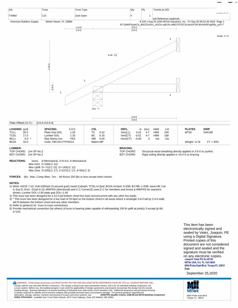
Design valid for use only with MiTek® connectors. This design is based only upon parameters shown, and is for an individual building component, not a truss system. Before use, the building designer must verify the applicability of design parameters and properly incorporate this design into the overall building design. Bracing indicated is to prevent buckling of individual truss web and/or chord members only. Additional temporary and permanent bracing is always required for stability and to prevent collapse with possible personal injury and property damage. For general guidance regarding the fabrication, storage, delivery, erection and bracing of trusses and truss systems, see ANSI/TPI1 Quality Criteria, DSB-89 and BCSI Building Component
available from Truss Plate Institute, 2670 Crain Highway, Suite 203 Waldorf, MD 20601Safety Information
WARNING - Verify design parameters and READ NOTES ON THIS AND INCLUDED MITEK REFERENCE PAGE MII-7473 rev. 5/19/2020 BEFORE USE.
6904 Parke East Blvd.Tampa, FL 36610
Job
776860
Truss
CJ3
Truss Type
Jack-Open
Qty
4
Ply
1
Tortola lot 202
Job Reference (optional)
T21407476
8.420 s Aug 25 2020 MiTek Industries, Inc. Fri Sep 25 09:22:46 2020 Page 1 American Builders Supply, Winter Haven, FL 33880ID:TpN0PSyykCd_d0OZXcRzv_zlGOs-uqFchLx4BO757DC1KzkoUPJFL8hJoNSFxgEBo_ya7r7
Scale: 1"=1'
1
2
3
4
2x4
3-0-03-0-0
-1-0-01-0-0
3-0-03-0-0
0-4-
3
1-10
-3
6.00 12
Plate Offsets (X,Y)-- [2:0-4-4,0-0-4]
LOADING (psf)TCLLTCDLBCLLBCDL
20.017.0
0.0 *10.0
SPACING-Plate Grip DOLLumber DOL Rep Stress IncrCode
2-0-01.251.25YES
FBC2017/TPI2014
CSI.TCBCWBMatrix-MP
0.220.160.00
DEFL.Vert(LL)Vert(CT)Horz(CT)
in0.01
-0.01-0.00
(loc)4-74-7
3
l/defl>999>999
n/a
L/d240180n/a
PLATESMT20
Weight: 11 lb FT = 20%
GRIP244/190
LUMBER-TOP CHORD 2x4 SP No.2BOT CHORD 2x4 SP No.2
BRACING-TOP CHORD Structural wood sheathing directly applied or 3-0-0 oc purlins.BOT CHORD Rigid ceiling directly applied or 10-0-0 oc bracing.
REACTIONS. (size) 3=Mechanical, 2=0-4-0, 4=MechanicalMax Horz 2=140(LC 12)Max Uplift 3=-71(LC 12), 2=-143(LC 12)Max Grav 3=100(LC 17), 2=227(LC 17), 4=55(LC 3)
FORCES. (lb) - Max. Comp./Max. Ten. - All forces 250 (lb) or less except when shown.
NOTES-1) Wind: ASCE 7-10; Vult=150mph (3-second gust) Vasd=116mph; TCDL=4.2psf; BCDL=6.0psf; h=25ft; B=78ft; L=50ft; eave=3ft; Cat.
II; Exp D; Encl., GCpi=0.18; MWFRS (directional) and C-C Corner(3) zone;C-C for members and forces & MWFRS for reactionsshown; Lumber DOL=1.60 plate grip DOL=1.60
2) This truss has been designed for a 10.0 psf bottom chord live load nonconcurrent with any other live loads.3) * This truss has been designed for a live load of 20.0psf on the bottom chord in all areas where a rectangle 3-6-0 tall by 2-0-0 wide
will fit between the bottom chord and any other members.4) Refer to girder(s) for truss to truss connections.5) Provide mechanical connection (by others) of truss to bearing plate capable of withstanding 100 lb uplift at joint(s) 3 except (jt=lb)
2=143.
This item has beenelectronically signed andsealed by Velez, Joaquin, PEusing a Digital Signature.Printed copies of thisdocument are not consideredsigned and sealed and thesignature must be verified on any electronic copies.
September 25,2020

Design valid for use only with MiTek® connectors. This design is based only upon parameters shown, and is for an individual building component, not a truss system. Before use, the building designer must verify the applicability of design parameters and properly incorporate this design into the overall building design. Bracing indicated is to prevent buckling of individual truss web and/or chord members only. Additional temporary and permanent bracing is always required for stability and to prevent collapse with possible personal injury and property damage. For general guidance regarding the fabrication, storage, delivery, erection and bracing of trusses and truss systems, see ANSI/TPI1 Quality Criteria, DSB-89 and BCSI Building Component
available from Truss Plate Institute, 2670 Crain Highway, Suite 203 Waldorf, MD 20601Safety Information
WARNING - Verify design parameters and READ NOTES ON THIS AND INCLUDED MITEK REFERENCE PAGE MII-7473 rev. 5/19/2020 BEFORE USE.
6904 Parke East Blvd.Tampa, FL 36610
Job
776860
Truss
CJ3A
Truss Type
Jack-Open
Qty
8
Ply
1
Tortola lot 202
Job Reference (optional)
T21407477
8.420 s Aug 25 2020 MiTek Industries, Inc. Fri Sep 25 09:22:47 2020 Page 1 American Builders Supply, Winter Haven, FL 33880ID:TpN0PSyykCd_d0OZXcRzv_zlGOs-M1o_uhyiyiFxkNnDugF11csQ5Y1YXqiO9K_kLQya7r6
Scale: 1"=1'
1
2
3
4
2x4
3-0-03-0-0
-1-0-01-0-0
3-0-03-0-0
0-4-
3
1-10
-3
6.00 12
Plate Offsets (X,Y)-- [2:0-4-4,0-0-4]
LOADING (psf)TCLLTCDLBCLLBCDL
20.017.0
0.0 *10.0
SPACING-Plate Grip DOLLumber DOL Rep Stress IncrCode
2-0-01.251.25YES
FBC2017/TPI2014
CSI.TCBCWBMatrix-MP
0.220.160.00
DEFL.Vert(LL)Vert(CT)Horz(CT)
in0.01
-0.01-0.00
(loc)4-74-7
3
l/defl>999>999
n/a
L/d240180n/a
PLATESMT20
Weight: 11 lb FT = 20%
GRIP244/190
LUMBER-TOP CHORD 2x4 SP No.2BOT CHORD 2x4 SP No.2
BRACING-TOP CHORD Structural wood sheathing directly applied or 3-0-0 oc purlins.BOT CHORD Rigid ceiling directly applied or 10-0-0 oc bracing.
REACTIONS. (size) 3=Mechanical, 2=0-8-0, 4=MechanicalMax Horz 2=140(LC 12)Max Uplift 3=-71(LC 12), 2=-143(LC 12)Max Grav 3=100(LC 17), 2=227(LC 17), 4=55(LC 3)
FORCES. (lb) - Max. Comp./Max. Ten. - All forces 250 (lb) or less except when shown.
NOTES-1) Wind: ASCE 7-10; Vult=150mph (3-second gust) Vasd=116mph; TCDL=4.2psf; BCDL=6.0psf; h=25ft; B=78ft; L=50ft; eave=3ft; Cat.
II; Exp D; Encl., GCpi=0.18; MWFRS (directional) and C-C Corner(3) zone; porch right exposed;C-C for members and forces &MWFRS for reactions shown; Lumber DOL=1.60 plate grip DOL=1.60
2) This truss has been designed for a 10.0 psf bottom chord live load nonconcurrent with any other live loads.3) * This truss has been designed for a live load of 20.0psf on the bottom chord in all areas where a rectangle 3-6-0 tall by 2-0-0 wide
will fit between the bottom chord and any other members.4) Refer to girder(s) for truss to truss connections.5) Provide mechanical connection (by others) of truss to bearing plate capable of withstanding 100 lb uplift at joint(s) 3 except (jt=lb)
2=143.
This item has beenelectronically signed andsealed by Velez, Joaquin, PEusing a Digital Signature.Printed copies of thisdocument are not consideredsigned and sealed and thesignature must be verified on any electronic copies.
September 25,2020
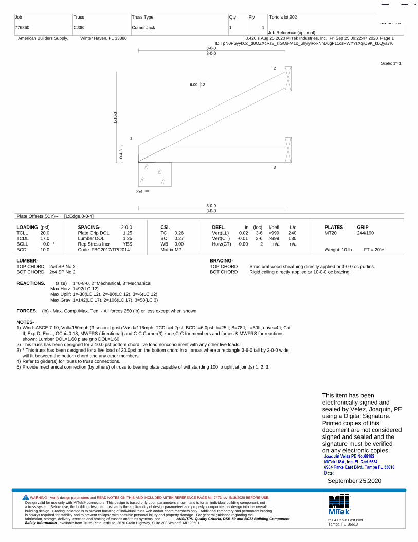
Design valid for use only with MiTek® connectors. This design is based only upon parameters shown, and is for an individual building component, not a truss system. Before use, the building designer must verify the applicability of design parameters and properly incorporate this design into the overall building design. Bracing indicated is to prevent buckling of individual truss web and/or chord members only. Additional temporary and permanent bracing is always required for stability and to prevent collapse with possible personal injury and property damage. For general guidance regarding the fabrication, storage, delivery, erection and bracing of trusses and truss systems, see ANSI/TPI1 Quality Criteria, DSB-89 and BCSI Building Component
available from Truss Plate Institute, 2670 Crain Highway, Suite 203 Waldorf, MD 20601Safety Information
WARNING - Verify design parameters and READ NOTES ON THIS AND INCLUDED MITEK REFERENCE PAGE MII-7473 rev. 5/19/2020 BEFORE USE.
6904 Parke East Blvd.Tampa, FL 36610
Job
776860
Truss
CJ3B
Truss Type
Corner Jack
Qty
1
Ply
1
Tortola lot 202
Job Reference (optional)
T21407478
8.420 s Aug 25 2020 MiTek Industries, Inc. Fri Sep 25 09:22:47 2020 Page 1 American Builders Supply, Winter Haven, FL 33880ID:TpN0PSyykCd_d0OZXcRzv_zlGOs-M1o_uhyiyiFxkNnDugF11csPWY?sXqiO9K_kLQya7r6
Scale: 1"=1'
1
2
3
2x4
3-0-03-0-0
3-0-03-0-0
0-4-
3
1-10
-3
6.00 12
Plate Offsets (X,Y)-- [1:Edge,0-0-4]
LOADING (psf)TCLLTCDLBCLLBCDL
20.017.0
0.0 *10.0
SPACING-Plate Grip DOLLumber DOL Rep Stress IncrCode
2-0-01.251.25YES
FBC2017/TPI2014
CSI.TCBCWBMatrix-MP
0.260.270.00
DEFL.Vert(LL)Vert(CT)Horz(CT)
in0.02
-0.01-0.00
(loc)3-63-6
2
l/defl>999>999
n/a
L/d240180n/a
PLATESMT20
Weight: 10 lb FT = 20%
GRIP244/190
LUMBER-TOP CHORD 2x4 SP No.2BOT CHORD 2x4 SP No.2
BRACING-TOP CHORD Structural wood sheathing directly applied or 3-0-0 oc purlins.BOT CHORD Rigid ceiling directly applied or 10-0-0 oc bracing.
REACTIONS. (size) 1=0-8-0, 2=Mechanical, 3=MechanicalMax Horz 1=92(LC 12)Max Uplift 1=-38(LC 12), 2=-80(LC 12), 3=-6(LC 12)Max Grav 1=142(LC 17), 2=106(LC 17), 3=58(LC 3)
FORCES. (lb) - Max. Comp./Max. Ten. - All forces 250 (lb) or less except when shown.
NOTES-1) Wind: ASCE 7-10; Vult=150mph (3-second gust) Vasd=116mph; TCDL=4.2psf; BCDL=6.0psf; h=25ft; B=78ft; L=50ft; eave=4ft; Cat.
II; Exp D; Encl., GCpi=0.18; MWFRS (directional) and C-C Corner(3) zone;C-C for members and forces & MWFRS for reactionsshown; Lumber DOL=1.60 plate grip DOL=1.60
2) This truss has been designed for a 10.0 psf bottom chord live load nonconcurrent with any other live loads.3) * This truss has been designed for a live load of 20.0psf on the bottom chord in all areas where a rectangle 3-6-0 tall by 2-0-0 wide
will fit between the bottom chord and any other members.4) Refer to girder(s) for truss to truss connections.5) Provide mechanical connection (by others) of truss to bearing plate capable of withstanding 100 lb uplift at joint(s) 1, 2, 3.
This item has beenelectronically signed andsealed by Velez, Joaquin, PEusing a Digital Signature.Printed copies of thisdocument are not consideredsigned and sealed and thesignature must be verified on any electronic copies.
September 25,2020
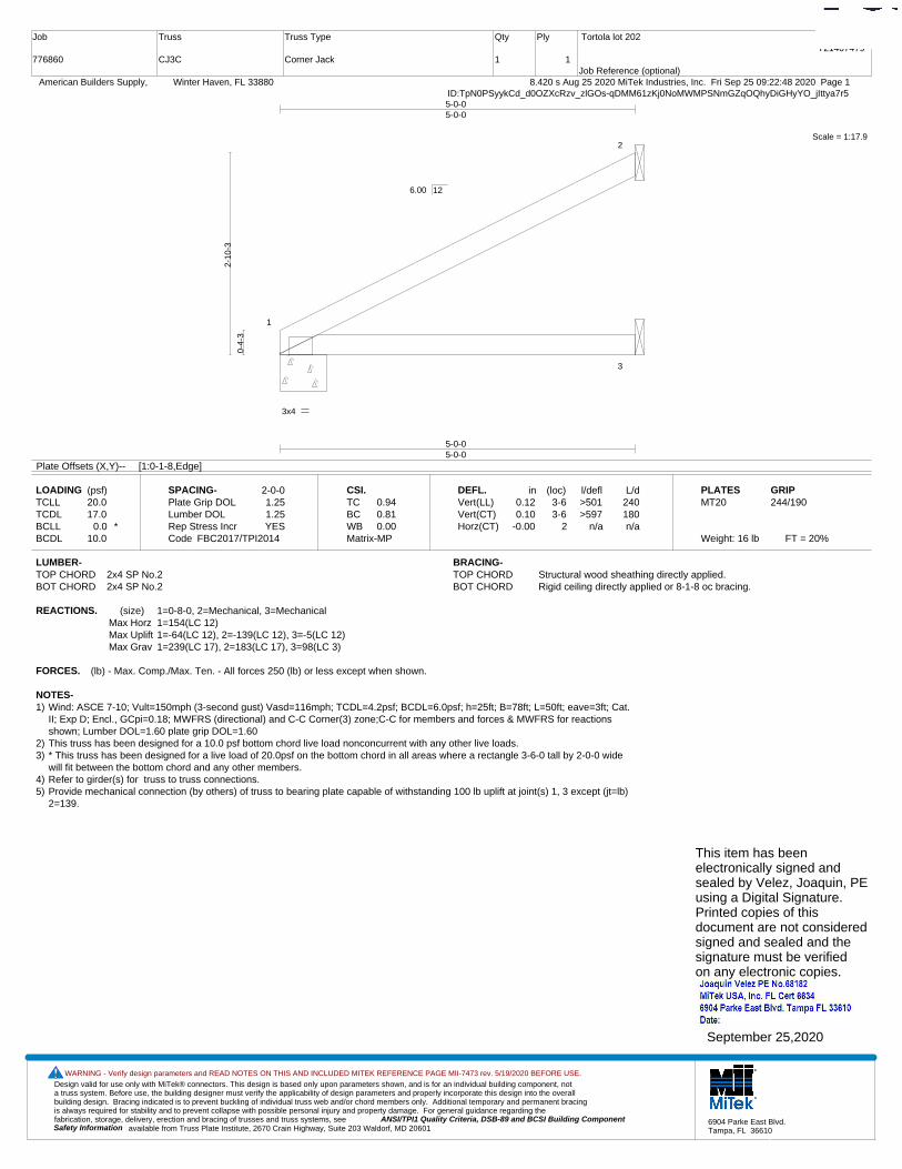
Design valid for use only with MiTek® connectors. This design is based only upon parameters shown, and is for an individual building component, not a truss system. Before use, the building designer must verify the applicability of design parameters and properly incorporate this design into the overall building design. Bracing indicated is to prevent buckling of individual truss web and/or chord members only. Additional temporary and permanent bracing is always required for stability and to prevent collapse with possible personal injury and property damage. For general guidance regarding the fabrication, storage, delivery, erection and bracing of trusses and truss systems, see ANSI/TPI1 Quality Criteria, DSB-89 and BCSI Building Component
available from Truss Plate Institute, 2670 Crain Highway, Suite 203 Waldorf, MD 20601Safety Information
WARNING - Verify design parameters and READ NOTES ON THIS AND INCLUDED MITEK REFERENCE PAGE MII-7473 rev. 5/19/2020 BEFORE USE.
6904 Parke East Blvd.Tampa, FL 36610
Job
776860
Truss
CJ3C
Truss Type
Corner Jack
Qty
1
Ply
1
Tortola lot 202
Job Reference (optional)
T21407479
8.420 s Aug 25 2020 MiTek Industries, Inc. Fri Sep 25 09:22:48 2020 Page 1 American Builders Supply, Winter Haven, FL 33880ID:TpN0PSyykCd_d0OZXcRzv_zlGOs-qDMM61zKj0NoMWMPSNmGZqOQhyDiGHyYO_jIttya7r5
Scale = 1:17.9
1
2
3
3x4
5-0-05-0-0
5-0-05-0-0
0-4-
3
2-10
-3
6.00 12
Plate Offsets (X,Y)-- [1:0-1-8,Edge]
LOADING (psf)TCLLTCDLBCLLBCDL
20.017.0
0.0 *10.0
SPACING-Plate Grip DOLLumber DOL Rep Stress IncrCode
2-0-01.251.25YES
FBC2017/TPI2014
CSI.TCBCWBMatrix-MP
0.940.810.00
DEFL.Vert(LL)Vert(CT)Horz(CT)
in0.120.10
-0.00
(loc)3-63-6
2
l/defl>501>597
n/a
L/d240180n/a
PLATESMT20
Weight: 16 lb FT = 20%
GRIP244/190
LUMBER-TOP CHORD 2x4 SP No.2BOT CHORD 2x4 SP No.2
BRACING-TOP CHORD Structural wood sheathing directly applied.BOT CHORD Rigid ceiling directly applied or 8-1-8 oc bracing.
REACTIONS. (size) 1=0-8-0, 2=Mechanical, 3=MechanicalMax Horz 1=154(LC 12)Max Uplift 1=-64(LC 12), 2=-139(LC 12), 3=-5(LC 12)Max Grav 1=239(LC 17), 2=183(LC 17), 3=98(LC 3)
FORCES. (lb) - Max. Comp./Max. Ten. - All forces 250 (lb) or less except when shown.
NOTES-1) Wind: ASCE 7-10; Vult=150mph (3-second gust) Vasd=116mph; TCDL=4.2psf; BCDL=6.0psf; h=25ft; B=78ft; L=50ft; eave=3ft; Cat.
II; Exp D; Encl., GCpi=0.18; MWFRS (directional) and C-C Corner(3) zone;C-C for members and forces & MWFRS for reactionsshown; Lumber DOL=1.60 plate grip DOL=1.60
2) This truss has been designed for a 10.0 psf bottom chord live load nonconcurrent with any other live loads.3) * This truss has been designed for a live load of 20.0psf on the bottom chord in all areas where a rectangle 3-6-0 tall by 2-0-0 wide
will fit between the bottom chord and any other members.4) Refer to girder(s) for truss to truss connections.5) Provide mechanical connection (by others) of truss to bearing plate capable of withstanding 100 lb uplift at joint(s) 1, 3 except (jt=lb)
2=139.
This item has beenelectronically signed andsealed by Velez, Joaquin, PEusing a Digital Signature.Printed copies of thisdocument are not consideredsigned and sealed and thesignature must be verified on any electronic copies.
September 25,2020
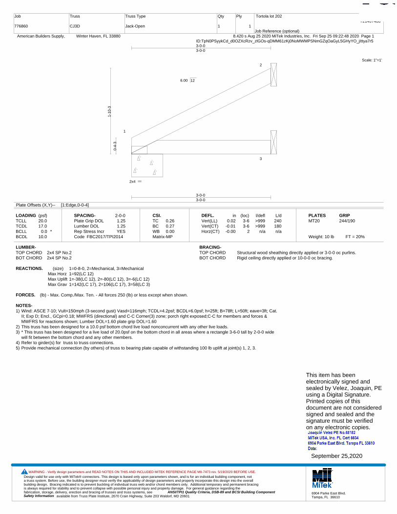
Design valid for use only with MiTek® connectors. This design is based only upon parameters shown, and is for an individual building component, not a truss system. Before use, the building designer must verify the applicability of design parameters and properly incorporate this design into the overall building design. Bracing indicated is to prevent buckling of individual truss web and/or chord members only. Additional temporary and permanent bracing is always required for stability and to prevent collapse with possible personal injury and property damage. For general guidance regarding the fabrication, storage, delivery, erection and bracing of trusses and truss systems, see ANSI/TPI1 Quality Criteria, DSB-89 and BCSI Building Component
available from Truss Plate Institute, 2670 Crain Highway, Suite 203 Waldorf, MD 20601Safety Information
WARNING - Verify design parameters and READ NOTES ON THIS AND INCLUDED MITEK REFERENCE PAGE MII-7473 rev. 5/19/2020 BEFORE USE.
6904 Parke East Blvd.Tampa, FL 36610
Job
776860
Truss
CJ3D
Truss Type
Jack-Open
Qty
1
Ply
1
Tortola lot 202
Job Reference (optional)
T21407480
8.420 s Aug 25 2020 MiTek Industries, Inc. Fri Sep 25 09:22:48 2020 Page 1 American Builders Supply, Winter Haven, FL 33880ID:TpN0PSyykCd_d0OZXcRzv_zlGOs-qDMM61zKj0NoMWMPSNmGZqOaGyL5GHyYO_jIttya7r5
Scale: 1"=1'
1
2
3
2x4
3-0-03-0-0
3-0-03-0-0
0-4-
3
1-10
-3
6.00 12
Plate Offsets (X,Y)-- [1:Edge,0-0-4]
LOADING (psf)TCLLTCDLBCLLBCDL
20.017.0
0.0 *10.0
SPACING-Plate Grip DOLLumber DOL Rep Stress IncrCode
2-0-01.251.25YES
FBC2017/TPI2014
CSI.TCBCWBMatrix-MP
0.260.270.00
DEFL.Vert(LL)Vert(CT)Horz(CT)
in0.02
-0.01-0.00
(loc)3-63-6
2
l/defl>999>999
n/a
L/d240180n/a
PLATESMT20
Weight: 10 lb FT = 20%
GRIP244/190
LUMBER-TOP CHORD 2x4 SP No.2BOT CHORD 2x4 SP No.2
BRACING-TOP CHORD Structural wood sheathing directly applied or 3-0-0 oc purlins.BOT CHORD Rigid ceiling directly applied or 10-0-0 oc bracing.
REACTIONS. (size) 1=0-8-0, 2=Mechanical, 3=MechanicalMax Horz 1=92(LC 12)Max Uplift 1=-38(LC 12), 2=-80(LC 12), 3=-6(LC 12)Max Grav 1=142(LC 17), 2=106(LC 17), 3=58(LC 3)
FORCES. (lb) - Max. Comp./Max. Ten. - All forces 250 (lb) or less except when shown.
NOTES-1) Wind: ASCE 7-10; Vult=150mph (3-second gust) Vasd=116mph; TCDL=4.2psf; BCDL=6.0psf; h=25ft; B=78ft; L=50ft; eave=3ft; Cat.
II; Exp D; Encl., GCpi=0.18; MWFRS (directional) and C-C Corner(3) zone; porch right exposed;C-C for members and forces &MWFRS for reactions shown; Lumber DOL=1.60 plate grip DOL=1.60
2) This truss has been designed for a 10.0 psf bottom chord live load nonconcurrent with any other live loads.3) * This truss has been designed for a live load of 20.0psf on the bottom chord in all areas where a rectangle 3-6-0 tall by 2-0-0 wide
will fit between the bottom chord and any other members.4) Refer to girder(s) for truss to truss connections.5) Provide mechanical connection (by others) of truss to bearing plate capable of withstanding 100 lb uplift at joint(s) 1, 2, 3.
This item has beenelectronically signed andsealed by Velez, Joaquin, PEusing a Digital Signature.Printed copies of thisdocument are not consideredsigned and sealed and thesignature must be verified on any electronic copies.
September 25,2020

Design valid for use only with MiTek® connectors. This design is based only upon parameters shown, and is for an individual building component, not a truss system. Before use, the building designer must verify the applicability of design parameters and properly incorporate this design into the overall building design. Bracing indicated is to prevent buckling of individual truss web and/or chord members only. Additional temporary and permanent bracing is always required for stability and to prevent collapse with possible personal injury and property damage. For general guidance regarding the fabrication, storage, delivery, erection and bracing of trusses and truss systems, see ANSI/TPI1 Quality Criteria, DSB-89 and BCSI Building Component
available from Truss Plate Institute, 2670 Crain Highway, Suite 203 Waldorf, MD 20601Safety Information
WARNING - Verify design parameters and READ NOTES ON THIS AND INCLUDED MITEK REFERENCE PAGE MII-7473 rev. 5/19/2020 BEFORE USE.
6904 Parke East Blvd.Tampa, FL 36610
Job
776860
Truss
CJ3G
Truss Type
Jack-Open
Qty
4
Ply
1
Tortola lot 202
Job Reference (optional)
T21407481
8.420 s Aug 25 2020 MiTek Industries, Inc. Fri Sep 25 09:22:49 2020 Page 1 American Builders Supply, Winter Haven, FL 33880ID:TpN0PSyykCd_d0OZXcRzv_zlGOs-JPwkJN_yUJVf_gxb?5HV61xmLMj9?kChdeTrPJya7r4
Scale: 1"=1'
1
2
3
76
4
5
3x4
2x4
5x6
0-2-0
2-4-02-4-0
3-0-00-8-0
-1-0-01-0-0
2-4-02-4-0
3-0-00-8-0
0-4-
3
1-10
-3
1-2-
3
1-5-
8
0-8-
0
6.00 12
Plate Offsets (X,Y)-- [3:0-2-4,0-2-5]
LOADING (psf)TCLLTCDLBCLLBCDL
20.017.0
0.0 *10.0
SPACING-Plate Grip DOLLumber DOL Rep Stress IncrCode
2-0-01.251.25YES
FBC2017/TPI2014
CSI.TCBCWBMatrix-MR
0.240.160.00
DEFL.Vert(LL)Vert(CT)Horz(CT)
in0.020.02
-0.01
(loc)665
l/defl>999>999
n/a
L/d240180n/a
PLATESMT20
Weight: 13 lb FT = 20%
GRIP244/190
LUMBER-TOP CHORD 2x4 SP No.2BOT CHORD 2x4 SP No.2 *Except*
3-7: 2x4 SP No.3
BRACING-TOP CHORD Structural wood sheathing directly applied or 3-0-0 oc purlins.BOT CHORD Rigid ceiling directly applied or 6-0-0 oc bracing.
REACTIONS. (size) 4=Mechanical, 2=0-4-0, 5=MechanicalMax Horz 2=140(LC 12)Max Uplift 4=-47(LC 12), 2=-142(LC 12), 5=-17(LC 12)Max Grav 4=86(LC 17), 2=230(LC 17), 5=64(LC 17)
FORCES. (lb) - Max. Comp./Max. Ten. - All forces 250 (lb) or less except when shown.
NOTES-1) Wind: ASCE 7-10; Vult=150mph (3-second gust) Vasd=116mph; TCDL=4.2psf; BCDL=6.0psf; h=25ft; B=78ft; L=50ft; eave=3ft; Cat.
II; Exp D; Encl., GCpi=0.18; MWFRS (directional) and C-C Corner(3) zone;C-C for members and forces & MWFRS for reactionsshown; Lumber DOL=1.60 plate grip DOL=1.60
2) This truss has been designed for a 10.0 psf bottom chord live load nonconcurrent with any other live loads.3) * This truss has been designed for a live load of 20.0psf on the bottom chord in all areas where a rectangle 3-6-0 tall by 2-0-0 wide
will fit between the bottom chord and any other members.4) Refer to girder(s) for truss to truss connections.5) Provide mechanical connection (by others) of truss to bearing plate capable of withstanding 100 lb uplift at joint(s) 4, 5 except (jt=lb)
2=142.
This item has beenelectronically signed andsealed by Velez, Joaquin, PEusing a Digital Signature.Printed copies of thisdocument are not consideredsigned and sealed and thesignature must be verified on any electronic copies.
September 25,2020

Design valid for use only with MiTek® connectors. This design is based only upon parameters shown, and is for an individual building component, not a truss system. Before use, the building designer must verify the applicability of design parameters and properly incorporate this design into the overall building design. Bracing indicated is to prevent buckling of individual truss web and/or chord members only. Additional temporary and permanent bracing is always required for stability and to prevent collapse with possible personal injury and property damage. For general guidance regarding the fabrication, storage, delivery, erection and bracing of trusses and truss systems, see ANSI/TPI1 Quality Criteria, DSB-89 and BCSI Building Component
available from Truss Plate Institute, 2670 Crain Highway, Suite 203 Waldorf, MD 20601Safety Information
WARNING - Verify design parameters and READ NOTES ON THIS AND INCLUDED MITEK REFERENCE PAGE MII-7473 rev. 5/19/2020 BEFORE USE.
6904 Parke East Blvd.Tampa, FL 36610
Job
776860
Truss
CJ5A
Truss Type
Jack-Open
Qty
6
Ply
1
Tortola lot 202
Job Reference (optional)
T21407482
8.420 s Aug 25 2020 MiTek Industries, Inc. Fri Sep 25 09:22:50 2020 Page 1 American Builders Supply, Winter Haven, FL 33880ID:TpN0PSyykCd_d0OZXcRzv_zlGOs-ncU6Xi?aFddWbqWoZookeFUn4lxBkBSqsICPxlya7r3
Scale = 1:17.9
1
2
3
4
3x4
5-0-05-0-0
-1-0-01-0-0
5-0-05-0-0
0-4-
3
2-10
-3
2-5-
8 2-10
-3
6.00 12
Plate Offsets (X,Y)-- [2:0-2-0,Edge]
LOADING (psf)TCLLTCDLBCLLBCDL
20.017.0
0.0 *10.0
SPACING-Plate Grip DOLLumber DOL Rep Stress IncrCode
2-0-01.251.25YES
FBC2017/TPI2014
CSI.TCBCWBMatrix-MP
0.880.680.00
DEFL.Vert(LL)Vert(CT)Horz(CT)
in0.100.08
-0.00
(loc)4-74-7
3
l/defl>598>733
n/a
L/d240180n/a
PLATESMT20
Weight: 18 lb FT = 20%
GRIP244/190
LUMBER-TOP CHORD 2x4 SP No.2BOT CHORD 2x4 SP No.2
BRACING-TOP CHORD Structural wood sheathing directly applied or 2-2-0 oc purlins.BOT CHORD Rigid ceiling directly applied or 10-0-0 oc bracing.
REACTIONS. (size) 3=Mechanical, 2=0-8-0, 4=MechanicalMax Horz 2=202(LC 12)Max Uplift 3=-134(LC 12), 2=-162(LC 12)Max Grav 3=180(LC 17), 2=319(LC 17), 4=96(LC 3)
FORCES. (lb) - Max. Comp./Max. Ten. - All forces 250 (lb) or less except when shown.
NOTES-1) Wind: ASCE 7-10; Vult=150mph (3-second gust) Vasd=116mph; TCDL=4.2psf; BCDL=6.0psf; h=25ft; B=78ft; L=50ft; eave=5ft; Cat.
II; Exp D; Encl., GCpi=0.18; MWFRS (directional) and C-C Corner(3) zone; porch right exposed;C-C for members and forces &MWFRS for reactions shown; Lumber DOL=1.60 plate grip DOL=1.60
2) This truss has been designed for a 10.0 psf bottom chord live load nonconcurrent with any other live loads.3) * This truss has been designed for a live load of 20.0psf on the bottom chord in all areas where a rectangle 3-6-0 tall by 2-0-0 wide
will fit between the bottom chord and any other members.4) Refer to girder(s) for truss to truss connections.5) Provide mechanical connection (by others) of truss to bearing plate capable of withstanding 100 lb uplift at joint(s) except (jt=lb)
3=134, 2=162.
This item has beenelectronically signed andsealed by Velez, Joaquin, PEusing a Digital Signature.Printed copies of thisdocument are not consideredsigned and sealed and thesignature must be verified on any electronic copies.
September 25,2020

Design valid for use only with MiTek® connectors. This design is based only upon parameters shown, and is for an individual building component, not a truss system. Before use, the building designer must verify the applicability of design parameters and properly incorporate this design into the overall building design. Bracing indicated is to prevent buckling of individual truss web and/or chord members only. Additional temporary and permanent bracing is always required for stability and to prevent collapse with possible personal injury and property damage. For general guidance regarding the fabrication, storage, delivery, erection and bracing of trusses and truss systems, see ANSI/TPI1 Quality Criteria, DSB-89 and BCSI Building Component
available from Truss Plate Institute, 2670 Crain Highway, Suite 203 Waldorf, MD 20601Safety Information
WARNING - Verify design parameters and READ NOTES ON THIS AND INCLUDED MITEK REFERENCE PAGE MII-7473 rev. 5/19/2020 BEFORE USE.
6904 Parke East Blvd.Tampa, FL 36610
Job
776860
Truss
CJ5D
Truss Type
Jack-Open
Qty
1
Ply
1
Tortola lot 202
Job Reference (optional)
T21407483
8.420 s Aug 25 2020 MiTek Industries, Inc. Fri Sep 25 09:22:50 2020 Page 1 American Builders Supply, Winter Haven, FL 33880ID:TpN0PSyykCd_d0OZXcRzv_zlGOs-ncU6Xi?aFddWbqWoZookeFUmAlvAkBSqsICPxlya7r3
Scale = 1:17.9
1
2
3
3x4
5-0-05-0-0
5-0-05-0-0
0-4-
3
2-10
-3
6.00 12
Plate Offsets (X,Y)-- [1:0-1-8,Edge]
LOADING (psf)TCLLTCDLBCLLBCDL
20.017.0
0.0 *10.0
SPACING-Plate Grip DOLLumber DOL Rep Stress IncrCode
2-0-01.251.25YES
FBC2017/TPI2014
CSI.TCBCWBMatrix-MP
0.940.810.00
DEFL.Vert(LL)Vert(CT)Horz(CT)
in0.120.10
-0.00
(loc)3-63-6
2
l/defl>501>597
n/a
L/d240180n/a
PLATESMT20
Weight: 16 lb FT = 20%
GRIP244/190
LUMBER-TOP CHORD 2x4 SP No.2BOT CHORD 2x4 SP No.2
BRACING-TOP CHORD Structural wood sheathing directly applied.BOT CHORD Rigid ceiling directly applied or 8-1-8 oc bracing.
REACTIONS. (size) 1=0-8-0, 2=Mechanical, 3=MechanicalMax Horz 1=154(LC 12)Max Uplift 1=-64(LC 12), 2=-139(LC 12), 3=-5(LC 12)Max Grav 1=239(LC 17), 2=183(LC 17), 3=98(LC 3)
FORCES. (lb) - Max. Comp./Max. Ten. - All forces 250 (lb) or less except when shown.
NOTES-1) Wind: ASCE 7-10; Vult=150mph (3-second gust) Vasd=116mph; TCDL=4.2psf; BCDL=6.0psf; h=25ft; B=78ft; L=50ft; eave=5ft; Cat.
II; Exp D; Encl., GCpi=0.18; MWFRS (directional) and C-C Corner(3) zone; porch right exposed;C-C for members and forces &MWFRS for reactions shown; Lumber DOL=1.60 plate grip DOL=1.60
2) This truss has been designed for a 10.0 psf bottom chord live load nonconcurrent with any other live loads.3) * This truss has been designed for a live load of 20.0psf on the bottom chord in all areas where a rectangle 3-6-0 tall by 2-0-0 wide
will fit between the bottom chord and any other members.4) Refer to girder(s) for truss to truss connections.5) Provide mechanical connection (by others) of truss to bearing plate capable of withstanding 100 lb uplift at joint(s) 1, 3 except (jt=lb)
2=139.
This item has beenelectronically signed andsealed by Velez, Joaquin, PEusing a Digital Signature.Printed copies of thisdocument are not consideredsigned and sealed and thesignature must be verified on any electronic copies.
September 25,2020

Design valid for use only with MiTek® connectors. This design is based only upon parameters shown, and is for an individual building component, not a truss system. Before use, the building designer must verify the applicability of design parameters and properly incorporate this design into the overall building design. Bracing indicated is to prevent buckling of individual truss web and/or chord members only. Additional temporary and permanent bracing is always required for stability and to prevent collapse with possible personal injury and property damage. For general guidance regarding the fabrication, storage, delivery, erection and bracing of trusses and truss systems, see ANSI/TPI1 Quality Criteria, DSB-89 and BCSI Building Component
available from Truss Plate Institute, 2670 Crain Highway, Suite 203 Waldorf, MD 20601Safety Information
WARNING - Verify design parameters and READ NOTES ON THIS AND INCLUDED MITEK REFERENCE PAGE MII-7473 rev. 5/19/2020 BEFORE USE.
6904 Parke East Blvd.Tampa, FL 36610
Job
776860
Truss
CJ5G
Truss Type
Jack-Open
Qty
4
Ply
1
Tortola lot 202
Job Reference (optional)
T21407484
8.420 s Aug 25 2020 MiTek Industries, Inc. Fri Sep 25 09:22:51 2020 Page 1 American Builders Supply, Winter Haven, FL 33880ID:TpN0PSyykCd_d0OZXcRzv_zlGOs-Fo2Uk2?C0xlND_5_7WJzBS0zA9GOTdh_4yyyUBya7r2
Scale = 1:17.0
1
2
3
76
4
5
3x4
3x4
7x8
0-2-0
2-4-02-4-0
5-0-02-8-0
-1-0-01-0-0
2-4-02-4-0
5-0-02-8-0
0-4-
3
2-10
-3
2-2-
3
0-8-
0
6.00 12
Plate Offsets (X,Y)-- [3:0-4-0,0-3-5]
LOADING (psf)TCLLTCDLBCLLBCDL
20.017.0
0.0 *10.0
SPACING-Plate Grip DOLLumber DOL Rep Stress IncrCode
2-0-01.251.25YES
FBC2017/TPI2014
CSI.TCBCWBMatrix-MR
0.790.750.00
DEFL.Vert(LL)Vert(CT)Horz(CT)
in0.180.15
-0.09
(loc)665
l/defl>331>389
n/a
L/d240180n/a
PLATESMT20
Weight: 19 lb FT = 20%
GRIP244/190
LUMBER-TOP CHORD 2x4 SP No.2BOT CHORD 2x4 SP No.2 *Except*
3-7: 2x4 SP No.3
BRACING-TOP CHORD Structural wood sheathing directly applied or 5-0-0 oc purlins.BOT CHORD Rigid ceiling directly applied or 6-0-0 oc bracing.
REACTIONS. (size) 4=Mechanical, 2=0-4-0, 5=MechanicalMax Horz 2=202(LC 12)Max Uplift 4=-110(LC 12), 2=-159(LC 12), 5=-20(LC 12)Max Grav 4=163(LC 17), 2=324(LC 17), 5=100(LC 3)
FORCES. (lb) - Max. Comp./Max. Ten. - All forces 250 (lb) or less except when shown.
NOTES-1) Wind: ASCE 7-10; Vult=150mph (3-second gust) Vasd=116mph; TCDL=4.2psf; BCDL=6.0psf; h=25ft; B=78ft; L=50ft; eave=5ft; Cat.
II; Exp D; Encl., GCpi=0.18; MWFRS (directional) and C-C Corner(3) zone;C-C for members and forces & MWFRS for reactionsshown; Lumber DOL=1.60 plate grip DOL=1.60
2) This truss has been designed for a 10.0 psf bottom chord live load nonconcurrent with any other live loads.3) * This truss has been designed for a live load of 20.0psf on the bottom chord in all areas where a rectangle 3-6-0 tall by 2-0-0 wide
will fit between the bottom chord and any other members.4) Refer to girder(s) for truss to truss connections.5) Provide mechanical connection (by others) of truss to bearing plate capable of withstanding 100 lb uplift at joint(s) 5 except (jt=lb)
4=110, 2=159.
This item has beenelectronically signed andsealed by Velez, Joaquin, PEusing a Digital Signature.Printed copies of thisdocument are not consideredsigned and sealed and thesignature must be verified on any electronic copies.
September 25,2020
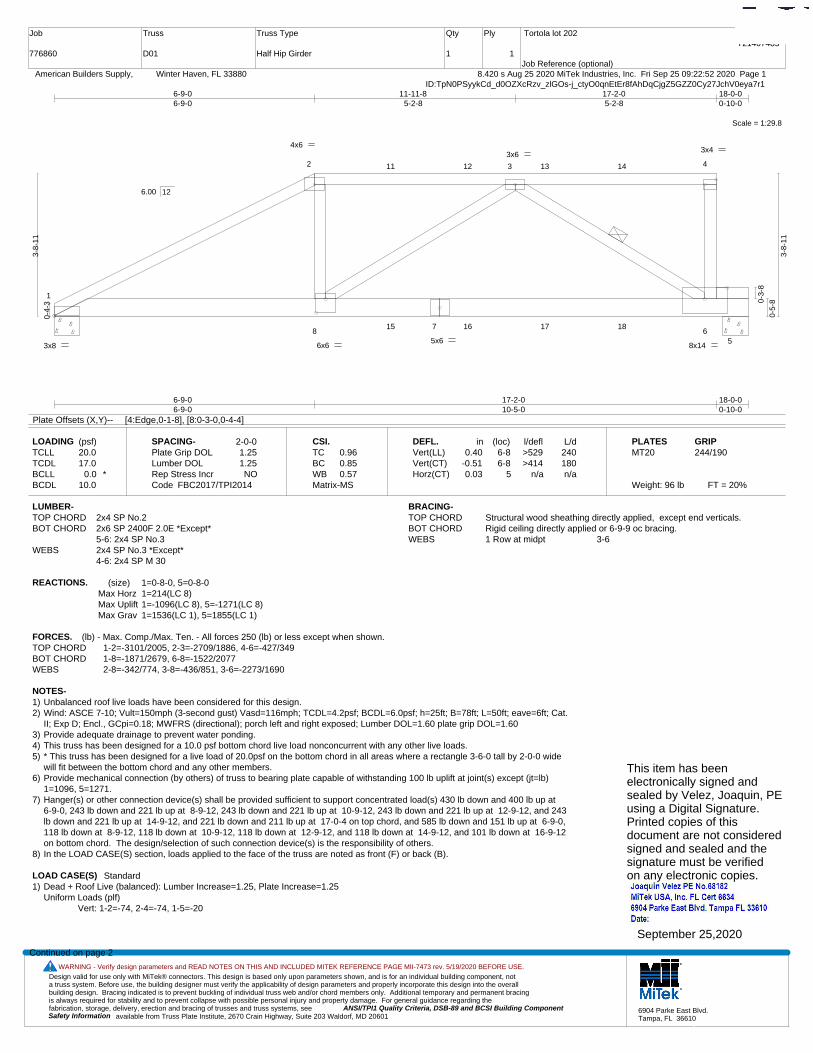
Design valid for use only with MiTek® connectors. This design is based only upon parameters shown, and is for an individual building component, not a truss system. Before use, the building designer must verify the applicability of design parameters and properly incorporate this design into the overall building design. Bracing indicated is to prevent buckling of individual truss web and/or chord members only. Additional temporary and permanent bracing is always required for stability and to prevent collapse with possible personal injury and property damage. For general guidance regarding the fabrication, storage, delivery, erection and bracing of trusses and truss systems, see ANSI/TPI1 Quality Criteria, DSB-89 and BCSI Building Component
available from Truss Plate Institute, 2670 Crain Highway, Suite 203 Waldorf, MD 20601Safety Information
WARNING - Verify design parameters and READ NOTES ON THIS AND INCLUDED MITEK REFERENCE PAGE MII-7473 rev. 5/19/2020 BEFORE USE.
6904 Parke East Blvd.Tampa, FL 36610
Job
776860
Truss
D01
Truss Type
Half Hip Girder
Qty
1
Ply
1
Tortola lot 202
Job Reference (optional)
T21407485
8.420 s Aug 25 2020 MiTek Industries, Inc. Fri Sep 25 09:22:52 2020 Page 1 American Builders Supply, Winter Haven, FL 33880ID:TpN0PSyykCd_d0OZXcRzv_zlGOs-j_ctyO0qnEtEr8fAhDqCjgZ5GZZ0Cy27JchV0eya7r1
Scale = 1:29.8
1
2 3 4
87
65
11 12 13 14
15 16 17 18
3x8
4x6 3x4
8x14 5x6
6x6
3x6
6-9-06-9-0
17-2-010-5-0
18-0-00-10-0
6-9-06-9-0
11-11-85-2-8
17-2-05-2-8
18-0-00-10-0
0-4-
3
3-8-
11
0-3-
8
0-5-
8
3-8-
11
6.00 12
Plate Offsets (X,Y)-- [4:Edge,0-1-8], [8:0-3-0,0-4-4]
LOADING (psf)TCLLTCDLBCLLBCDL
20.017.0
0.0 *10.0
SPACING-Plate Grip DOLLumber DOL Rep Stress IncrCode
2-0-01.251.25NO
FBC2017/TPI2014
CSI.TCBCWBMatrix-MS
0.960.850.57
DEFL.Vert(LL)Vert(CT)Horz(CT)
in0.40
-0.510.03
(loc)6-86-8
5
l/defl>529>414
n/a
L/d240180n/a
PLATESMT20
Weight: 96 lb FT = 20%
GRIP244/190
LUMBER-TOP CHORD 2x4 SP No.2BOT CHORD 2x6 SP 2400F 2.0E *Except*
5-6: 2x4 SP No.3WEBS 2x4 SP No.3 *Except*
4-6: 2x4 SP M 30
BRACING-TOP CHORD Structural wood sheathing directly applied, except end verticals.BOT CHORD Rigid ceiling directly applied or 6-9-9 oc bracing.WEBS 1 Row at midpt 3-6
REACTIONS. (size) 1=0-8-0, 5=0-8-0Max Horz 1=214(LC 8)Max Uplift 1=-1096(LC 8), 5=-1271(LC 8)Max Grav 1=1536(LC 1), 5=1855(LC 1)
FORCES. (lb) - Max. Comp./Max. Ten. - All forces 250 (lb) or less except when shown.TOP CHORD 1-2=-3101/2005, 2-3=-2709/1886, 4-6=-427/349BOT CHORD 1-8=-1871/2679, 6-8=-1522/2077WEBS 2-8=-342/774, 3-8=-436/851, 3-6=-2273/1690
NOTES-1) Unbalanced roof live loads have been considered for this design.2) Wind: ASCE 7-10; Vult=150mph (3-second gust) Vasd=116mph; TCDL=4.2psf; BCDL=6.0psf; h=25ft; B=78ft; L=50ft; eave=6ft; Cat.
II; Exp D; Encl., GCpi=0.18; MWFRS (directional); porch left and right exposed; Lumber DOL=1.60 plate grip DOL=1.603) Provide adequate drainage to prevent water ponding.4) This truss has been designed for a 10.0 psf bottom chord live load nonconcurrent with any other live loads.5) * This truss has been designed for a live load of 20.0psf on the bottom chord in all areas where a rectangle 3-6-0 tall by 2-0-0 wide
will fit between the bottom chord and any other members.6) Provide mechanical connection (by others) of truss to bearing plate capable of withstanding 100 lb uplift at joint(s) except (jt=lb)
1=1096, 5=1271.7) Hanger(s) or other connection device(s) shall be provided sufficient to support concentrated load(s) 430 lb down and 400 lb up at
6-9-0, 243 lb down and 221 lb up at 8-9-12, 243 lb down and 221 lb up at 10-9-12, 243 lb down and 221 lb up at 12-9-12, and 243lb down and 221 lb up at 14-9-12, and 221 lb down and 211 lb up at 17-0-4 on top chord, and 585 lb down and 151 lb up at 6-9-0,118 lb down at 8-9-12, 118 lb down at 10-9-12, 118 lb down at 12-9-12, and 118 lb down at 14-9-12, and 101 lb down at 16-9-12on bottom chord. The design/selection of such connection device(s) is the responsibility of others.
8) In the LOAD CASE(S) section, loads applied to the face of the truss are noted as front (F) or back (B).
LOAD CASE(S) Standard1) Dead + Roof Live (balanced): Lumber Increase=1.25, Plate Increase=1.25
Uniform Loads (plf)Vert: 1-2=-74, 2-4=-74, 1-5=-20
Continued on page 2
This item has beenelectronically signed andsealed by Velez, Joaquin, PEusing a Digital Signature.Printed copies of thisdocument are not consideredsigned and sealed and thesignature must be verified on any electronic copies.
September 25,2020
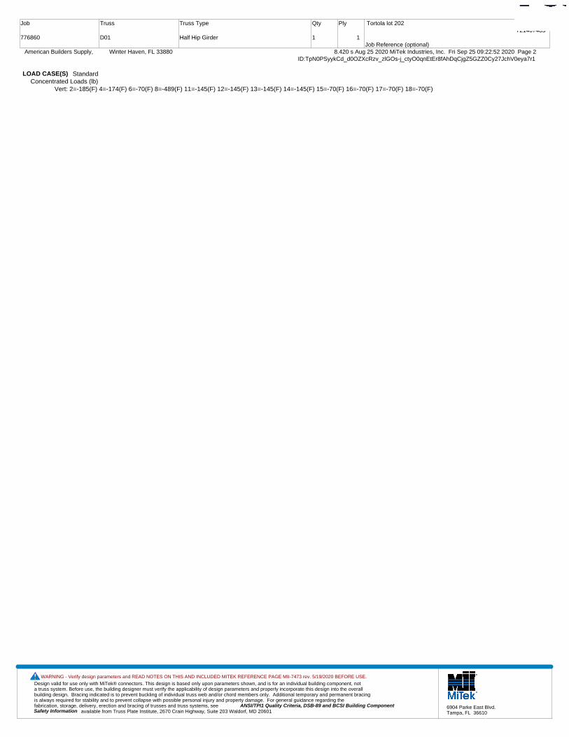
Design valid for use only with MiTek® connectors. This design is based only upon parameters shown, and is for an individual building component, not a truss system. Before use, the building designer must verify the applicability of design parameters and properly incorporate this design into the overall building design. Bracing indicated is to prevent buckling of individual truss web and/or chord members only. Additional temporary and permanent bracing is always required for stability and to prevent collapse with possible personal injury and property damage. For general guidance regarding the fabrication, storage, delivery, erection and bracing of trusses and truss systems, see ANSI/TPI1 Quality Criteria, DSB-89 and BCSI Building Component
available from Truss Plate Institute, 2670 Crain Highway, Suite 203 Waldorf, MD 20601Safety Information
WARNING - Verify design parameters and READ NOTES ON THIS AND INCLUDED MITEK REFERENCE PAGE MII-7473 rev. 5/19/2020 BEFORE USE.
6904 Parke East Blvd.Tampa, FL 36610
Job
776860
Truss
D01
Truss Type
Half Hip Girder
Qty
1
Ply
1
Tortola lot 202
Job Reference (optional)
T21407485
8.420 s Aug 25 2020 MiTek Industries, Inc. Fri Sep 25 09:22:52 2020 Page 2 American Builders Supply, Winter Haven, FL 33880ID:TpN0PSyykCd_d0OZXcRzv_zlGOs-j_ctyO0qnEtEr8fAhDqCjgZ5GZZ0Cy27JchV0eya7r1
LOAD CASE(S) StandardConcentrated Loads (lb)
Vert: 2=-185(F) 4=-174(F) 6=-70(F) 8=-489(F) 11=-145(F) 12=-145(F) 13=-145(F) 14=-145(F) 15=-70(F) 16=-70(F) 17=-70(F) 18=-70(F)
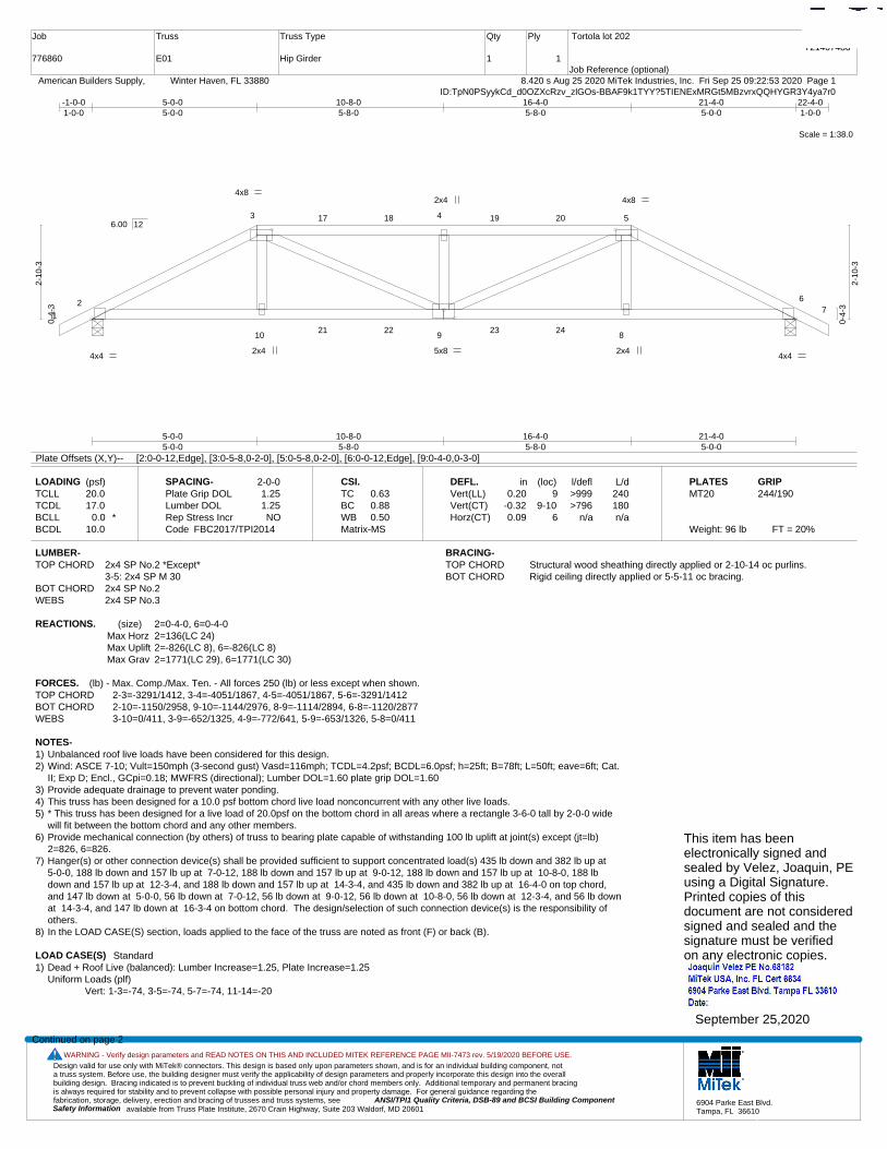
Design valid for use only with MiTek® connectors. This design is based only upon parameters shown, and is for an individual building component, not a truss system. Before use, the building designer must verify the applicability of design parameters and properly incorporate this design into the overall building design. Bracing indicated is to prevent buckling of individual truss web and/or chord members only. Additional temporary and permanent bracing is always required for stability and to prevent collapse with possible personal injury and property damage. For general guidance regarding the fabrication, storage, delivery, erection and bracing of trusses and truss systems, see ANSI/TPI1 Quality Criteria, DSB-89 and BCSI Building Component
available from Truss Plate Institute, 2670 Crain Highway, Suite 203 Waldorf, MD 20601Safety Information
WARNING - Verify design parameters and READ NOTES ON THIS AND INCLUDED MITEK REFERENCE PAGE MII-7473 rev. 5/19/2020 BEFORE USE.
6904 Parke East Blvd.Tampa, FL 36610
Job
776860
Truss
E01
Truss Type
Hip Girder
Qty
1
Ply
1
Tortola lot 202
Job Reference (optional)
T21407486
8.420 s Aug 25 2020 MiTek Industries, Inc. Fri Sep 25 09:22:53 2020 Page 1 American Builders Supply, Winter Haven, FL 33880ID:TpN0PSyykCd_d0OZXcRzv_zlGOs-BBAF9k1TYY?5TIENExMRGt5MBzvrxQQHYGR3Y4ya7r0
Scale = 1:38.0
1
2
3 4 5
67
10 9 8
17 18 19 20
21 22 23 24
4x8 4x8
4x4 2x4 5x8
2x4
2x4 4x4
5-0-05-0-0
10-8-05-8-0
16-4-05-8-0
21-4-05-0-0
-1-0-01-0-0
5-0-05-0-0
10-8-05-8-0
16-4-05-8-0
21-4-05-0-0
22-4-01-0-0
0-4-
3
2-10
-3
0-4-
3
2-10
-3
6.00 12
Plate Offsets (X,Y)-- [2:0-0-12,Edge], [3:0-5-8,0-2-0], [5:0-5-8,0-2-0], [6:0-0-12,Edge], [9:0-4-0,0-3-0]
LOADING (psf)TCLLTCDLBCLLBCDL
20.017.0
0.0 *10.0
SPACING-Plate Grip DOLLumber DOL Rep Stress IncrCode
2-0-01.251.25NO
FBC2017/TPI2014
CSI.TCBCWBMatrix-MS
0.630.880.50
DEFL.Vert(LL)Vert(CT)Horz(CT)
in0.20
-0.320.09
(loc)9
9-106
l/defl>999>796
n/a
L/d240180n/a
PLATESMT20
Weight: 96 lb FT = 20%
GRIP244/190
LUMBER-TOP CHORD 2x4 SP No.2 *Except*
3-5: 2x4 SP M 30BOT CHORD 2x4 SP No.2WEBS 2x4 SP No.3
BRACING-TOP CHORD Structural wood sheathing directly applied or 2-10-14 oc purlins.BOT CHORD Rigid ceiling directly applied or 5-5-11 oc bracing.
REACTIONS. (size) 2=0-4-0, 6=0-4-0Max Horz 2=136(LC 24)Max Uplift 2=-826(LC 8), 6=-826(LC 8)Max Grav 2=1771(LC 29), 6=1771(LC 30)
FORCES. (lb) - Max. Comp./Max. Ten. - All forces 250 (lb) or less except when shown.TOP CHORD 2-3=-3291/1412, 3-4=-4051/1867, 4-5=-4051/1867, 5-6=-3291/1412BOT CHORD 2-10=-1150/2958, 9-10=-1144/2976, 8-9=-1114/2894, 6-8=-1120/2877WEBS 3-10=0/411, 3-9=-652/1325, 4-9=-772/641, 5-9=-653/1326, 5-8=0/411
NOTES-1) Unbalanced roof live loads have been considered for this design.2) Wind: ASCE 7-10; Vult=150mph (3-second gust) Vasd=116mph; TCDL=4.2psf; BCDL=6.0psf; h=25ft; B=78ft; L=50ft; eave=6ft; Cat.
II; Exp D; Encl., GCpi=0.18; MWFRS (directional); Lumber DOL=1.60 plate grip DOL=1.603) Provide adequate drainage to prevent water ponding.4) This truss has been designed for a 10.0 psf bottom chord live load nonconcurrent with any other live loads.5) * This truss has been designed for a live load of 20.0psf on the bottom chord in all areas where a rectangle 3-6-0 tall by 2-0-0 wide
will fit between the bottom chord and any other members.6) Provide mechanical connection (by others) of truss to bearing plate capable of withstanding 100 lb uplift at joint(s) except (jt=lb)
2=826, 6=826.7) Hanger(s) or other connection device(s) shall be provided sufficient to support concentrated load(s) 435 lb down and 382 lb up at
5-0-0, 188 lb down and 157 lb up at 7-0-12, 188 lb down and 157 lb up at 9-0-12, 188 lb down and 157 lb up at 10-8-0, 188 lbdown and 157 lb up at 12-3-4, and 188 lb down and 157 lb up at 14-3-4, and 435 lb down and 382 lb up at 16-4-0 on top chord,and 147 lb down at 5-0-0, 56 lb down at 7-0-12, 56 lb down at 9-0-12, 56 lb down at 10-8-0, 56 lb down at 12-3-4, and 56 lb downat 14-3-4, and 147 lb down at 16-3-4 on bottom chord. The design/selection of such connection device(s) is the responsibility ofothers.
8) In the LOAD CASE(S) section, loads applied to the face of the truss are noted as front (F) or back (B).
LOAD CASE(S) Standard1) Dead + Roof Live (balanced): Lumber Increase=1.25, Plate Increase=1.25
Uniform Loads (plf)Vert: 1-3=-74, 3-5=-74, 5-7=-74, 11-14=-20
Continued on page 2
This item has beenelectronically signed andsealed by Velez, Joaquin, PEusing a Digital Signature.Printed copies of thisdocument are not consideredsigned and sealed and thesignature must be verified on any electronic copies.
September 25,2020
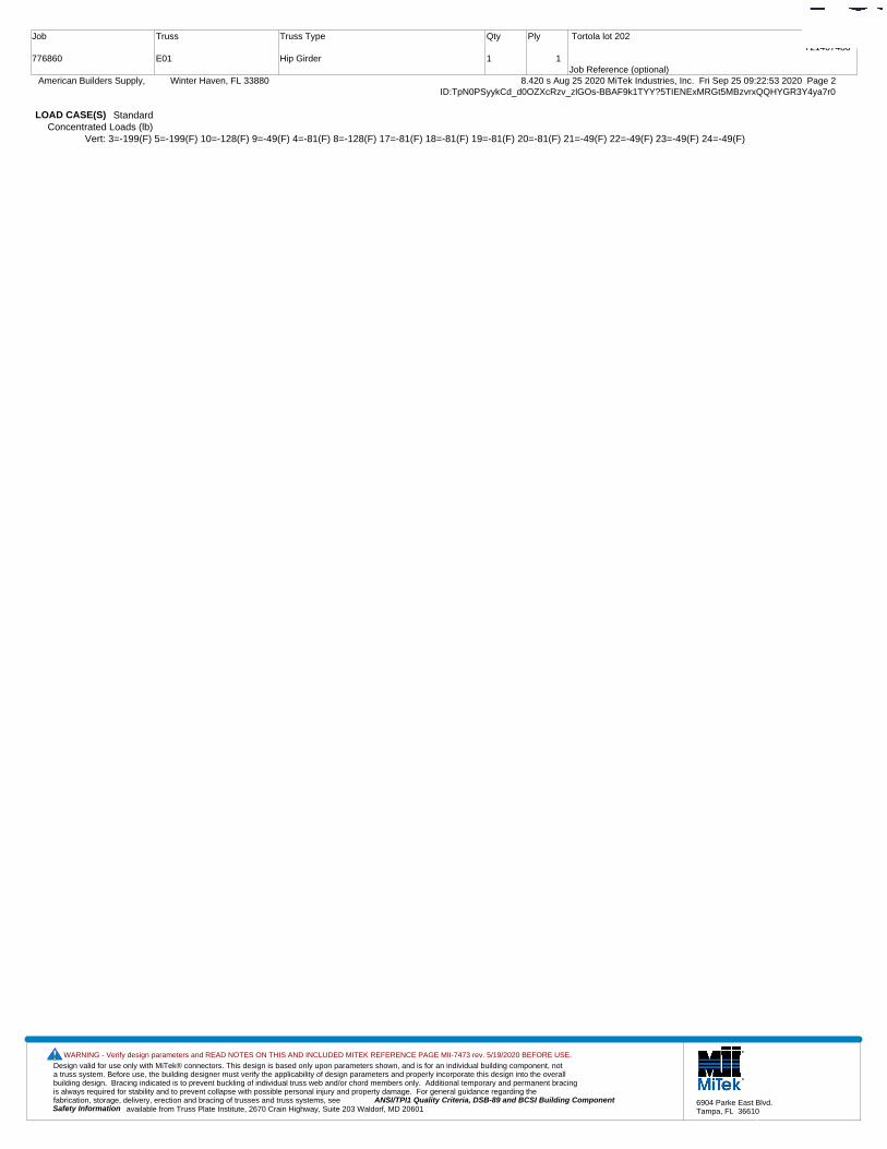
Design valid for use only with MiTek® connectors. This design is based only upon parameters shown, and is for an individual building component, not a truss system. Before use, the building designer must verify the applicability of design parameters and properly incorporate this design into the overall building design. Bracing indicated is to prevent buckling of individual truss web and/or chord members only. Additional temporary and permanent bracing is always required for stability and to prevent collapse with possible personal injury and property damage. For general guidance regarding the fabrication, storage, delivery, erection and bracing of trusses and truss systems, see ANSI/TPI1 Quality Criteria, DSB-89 and BCSI Building Component
available from Truss Plate Institute, 2670 Crain Highway, Suite 203 Waldorf, MD 20601Safety Information
WARNING - Verify design parameters and READ NOTES ON THIS AND INCLUDED MITEK REFERENCE PAGE MII-7473 rev. 5/19/2020 BEFORE USE.
6904 Parke East Blvd.Tampa, FL 36610
Job
776860
Truss
E01
Truss Type
Hip Girder
Qty
1
Ply
1
Tortola lot 202
Job Reference (optional)
T21407486
8.420 s Aug 25 2020 MiTek Industries, Inc. Fri Sep 25 09:22:53 2020 Page 2 American Builders Supply, Winter Haven, FL 33880ID:TpN0PSyykCd_d0OZXcRzv_zlGOs-BBAF9k1TYY?5TIENExMRGt5MBzvrxQQHYGR3Y4ya7r0
LOAD CASE(S) StandardConcentrated Loads (lb)
Vert: 3=-199(F) 5=-199(F) 10=-128(F) 9=-49(F) 4=-81(F) 8=-128(F) 17=-81(F) 18=-81(F) 19=-81(F) 20=-81(F) 21=-49(F) 22=-49(F) 23=-49(F) 24=-49(F)

Design valid for use only with MiTek® connectors. This design is based only upon parameters shown, and is for an individual building component, not a truss system. Before use, the building designer must verify the applicability of design parameters and properly incorporate this design into the overall building design. Bracing indicated is to prevent buckling of individual truss web and/or chord members only. Additional temporary and permanent bracing is always required for stability and to prevent collapse with possible personal injury and property damage. For general guidance regarding the fabrication, storage, delivery, erection and bracing of trusses and truss systems, see ANSI/TPI1 Quality Criteria, DSB-89 and BCSI Building Component
available from Truss Plate Institute, 2670 Crain Highway, Suite 203 Waldorf, MD 20601Safety Information
WARNING - Verify design parameters and READ NOTES ON THIS AND INCLUDED MITEK REFERENCE PAGE MII-7473 rev. 5/19/2020 BEFORE USE.
6904 Parke East Blvd.Tampa, FL 36610
Job
776860
Truss
E02
Truss Type
Hip
Qty
1
Ply
1
Tortola lot 202
Job Reference (optional)
T21407487
8.420 s Aug 25 2020 MiTek Industries, Inc. Fri Sep 25 09:22:54 2020 Page 1 American Builders Supply, Winter Haven, FL 33880ID:TpN0PSyykCd_d0OZXcRzv_zlGOs-fNjdN425Js7y4RpZoetgp4eTXNHSgx?QmwAc4Wya7r?
Scale = 1:38.0
1
2
3 4
56
98
7
16 17
5x10 MT20HS
5x6
4x4 3x4
2x4 3x4 4x4
7-0-07-0-0
14-4-07-4-0
21-4-07-0-0
-1-0-01-0-0
7-0-07-0-0
14-4-07-4-0
21-4-07-0-0
22-4-01-0-0
0-4-
3
3-10
-3
0-4-
3
3-10
-3
6.00 12
Plate Offsets (X,Y)-- [3:0-5-12,0-1-12], [4:0-3-8,0-2-4]
LOADING (psf)TCLLTCDLBCLLBCDL
20.017.0
0.0 *10.0
SPACING-Plate Grip DOLLumber DOL Rep Stress IncrCode
2-0-01.251.25YES
FBC2017/TPI2014
CSI.TCBCWBMatrix-MS
0.850.720.22
DEFL.Vert(LL)Vert(CT)Horz(CT)
in0.17
-0.220.04
(loc)7-159-12
5
l/defl>999>999
n/a
L/d240180n/a
PLATESMT20MT20HS
Weight: 91 lb FT = 20%
GRIP244/190187/143
LUMBER-TOP CHORD 2x4 SP No.2 *Except*
3-4: 2x4 SP M 30BOT CHORD 2x4 SP No.2WEBS 2x4 SP No.3
BRACING-TOP CHORD Structural wood sheathing directly applied or 2-2-0 oc purlins.BOT CHORD Rigid ceiling directly applied or 5-4-2 oc bracing.
REACTIONS. (size) 2=0-4-0, 5=0-4-0Max Horz 2=-181(LC 10)Max Uplift 2=-536(LC 12), 5=-536(LC 12)Max Grav 2=1077(LC 1), 5=1077(LC 1)
FORCES. (lb) - Max. Comp./Max. Ten. - All forces 250 (lb) or less except when shown.TOP CHORD 2-3=-1669/1099, 3-4=-1410/1119, 4-5=-1670/1099BOT CHORD 2-9=-768/1405, 7-9=-767/1413, 5-7=-774/1403WEBS 3-9=0/307, 4-7=0/307
NOTES-1) Unbalanced roof live loads have been considered for this design.2) Wind: ASCE 7-10; Vult=150mph (3-second gust) Vasd=116mph; TCDL=4.2psf; BCDL=6.0psf; h=25ft; B=78ft; L=50ft; eave=6ft; Cat.
II; Exp D; Encl., GCpi=0.18; MWFRS (directional) and C-C Exterior(2) -1-0-0 to 4-0-0, Interior(1) 4-0-0 to 7-0-0, Exterior(2) 7-0-0 to21-4-0, Interior(1) 21-4-0 to 22-4-0 zone;C-C for members and forces & MWFRS for reactions shown; Lumber DOL=1.60 plate gripDOL=1.60
3) Provide adequate drainage to prevent water ponding.4) All plates are MT20 plates unless otherwise indicated. 5) This truss has been designed for a 10.0 psf bottom chord live load nonconcurrent with any other live loads.6) * This truss has been designed for a live load of 20.0psf on the bottom chord in all areas where a rectangle 3-6-0 tall by 2-0-0 wide
will fit between the bottom chord and any other members.7) Provide mechanical connection (by others) of truss to bearing plate capable of withstanding 100 lb uplift at joint(s) except (jt=lb)
2=536, 5=536.
This item has beenelectronically signed andsealed by Velez, Joaquin, PEusing a Digital Signature.Printed copies of thisdocument are not consideredsigned and sealed and thesignature must be verified on any electronic copies.
September 25,2020

Design valid for use only with MiTek® connectors. This design is based only upon parameters shown, and is for an individual building component, not a truss system. Before use, the building designer must verify the applicability of design parameters and properly incorporate this design into the overall building design. Bracing indicated is to prevent buckling of individual truss web and/or chord members only. Additional temporary and permanent bracing is always required for stability and to prevent collapse with possible personal injury and property damage. For general guidance regarding the fabrication, storage, delivery, erection and bracing of trusses and truss systems, see ANSI/TPI1 Quality Criteria, DSB-89 and BCSI Building Component
available from Truss Plate Institute, 2670 Crain Highway, Suite 203 Waldorf, MD 20601Safety Information
WARNING - Verify design parameters and READ NOTES ON THIS AND INCLUDED MITEK REFERENCE PAGE MII-7473 rev. 5/19/2020 BEFORE USE.
6904 Parke East Blvd.Tampa, FL 36610
Job
776860
Truss
E03
Truss Type
Hip
Qty
1
Ply
1
Tortola lot 202
Job Reference (optional)
T21407488
8.420 s Aug 25 2020 MiTek Industries, Inc. Fri Sep 25 09:22:55 2020 Page 1 American Builders Supply, Winter Haven, FL 33880ID:TpN0PSyykCd_d0OZXcRzv_zlGOs-7ZH?aQ2j39FpibOlMMOvLIBk8md2PNTa?awAdzya7r_
Scale = 1:38.0
1
2
3
4 5
6
78
1110
9
18
19 20
21
4x4 4x8
4x4 4x4
3x8
2x4
3x4
2x4
4x4
9-0-09-0-0
12-4-03-4-0
21-4-09-0-0
-1-0-01-0-0
4-6-104-6-10
9-0-04-5-6
12-4-03-4-0
16-9-64-5-6
21-4-04-6-10
22-4-01-0-0
0-4-
3
4-10
-3
0-4-
3
4-10
-3
6.00 12
Plate Offsets (X,Y)-- [5:0-5-4,0-2-0]
LOADING (psf)TCLLTCDLBCLLBCDL
20.017.0
0.0 *10.0
SPACING-Plate Grip DOLLumber DOL Rep Stress IncrCode
2-0-01.251.25YES
FBC2017/TPI2014
CSI.TCBCWBMatrix-MS
0.470.760.27
DEFL.Vert(LL)Vert(CT)Horz(CT)
in-0.15-0.340.05
(loc)9-179-17
7
l/defl>999>752
n/a
L/d240180n/a
PLATESMT20
Weight: 105 lb FT = 20%
GRIP244/190
LUMBER-TOP CHORD 2x4 SP No.2BOT CHORD 2x4 SP No.2WEBS 2x4 SP No.3
BRACING-TOP CHORD Structural wood sheathing directly applied or 4-1-4 oc purlins.BOT CHORD Rigid ceiling directly applied or 5-9-8 oc bracing.
REACTIONS. (size) 2=0-4-0, 7=0-4-0Max Horz 2=226(LC 11)Max Uplift 2=-536(LC 12), 7=-536(LC 12)Max Grav 2=1077(LC 1), 7=1077(LC 1)
FORCES. (lb) - Max. Comp./Max. Ten. - All forces 250 (lb) or less except when shown.TOP CHORD 2-3=-1781/1264, 3-4=-1388/941, 4-5=-1173/934, 5-6=-1387/940, 6-7=-1781/1263BOT CHORD 2-11=-1010/1642, 9-11=-523/1172, 7-9=-1015/1571WEBS 3-11=-521/549, 4-11=-178/355, 5-9=-164/355, 6-9=-523/549
NOTES-1) Unbalanced roof live loads have been considered for this design.2) Wind: ASCE 7-10; Vult=150mph (3-second gust) Vasd=116mph; TCDL=4.2psf; BCDL=6.0psf; h=25ft; B=78ft; L=50ft; eave=6ft; Cat.
II; Exp D; Encl., GCpi=0.18; MWFRS (directional) and C-C Exterior(2) -1-0-0 to 4-0-0, Interior(1) 4-0-0 to 9-0-0, Exterior(2) 9-0-0 to19-4-14, Interior(1) 19-4-14 to 22-4-0 zone;C-C for members and forces & MWFRS for reactions shown; Lumber DOL=1.60 plategrip DOL=1.60
3) Provide adequate drainage to prevent water ponding.4) This truss has been designed for a 10.0 psf bottom chord live load nonconcurrent with any other live loads.5) * This truss has been designed for a live load of 20.0psf on the bottom chord in all areas where a rectangle 3-6-0 tall by 2-0-0 wide
will fit between the bottom chord and any other members.6) Provide mechanical connection (by others) of truss to bearing plate capable of withstanding 100 lb uplift at joint(s) except (jt=lb)
2=536, 7=536.
This item has beenelectronically signed andsealed by Velez, Joaquin, PEusing a Digital Signature.Printed copies of thisdocument are not consideredsigned and sealed and thesignature must be verified on any electronic copies.
September 25,2020

Design valid for use only with MiTek® connectors. This design is based only upon parameters shown, and is for an individual building component, not a truss system. Before use, the building designer must verify the applicability of design parameters and properly incorporate this design into the overall building design. Bracing indicated is to prevent buckling of individual truss web and/or chord members only. Additional temporary and permanent bracing is always required for stability and to prevent collapse with possible personal injury and property damage. For general guidance regarding the fabrication, storage, delivery, erection and bracing of trusses and truss systems, see ANSI/TPI1 Quality Criteria, DSB-89 and BCSI Building Component
available from Truss Plate Institute, 2670 Crain Highway, Suite 203 Waldorf, MD 20601Safety Information
WARNING - Verify design parameters and READ NOTES ON THIS AND INCLUDED MITEK REFERENCE PAGE MII-7473 rev. 5/19/2020 BEFORE USE.
6904 Parke East Blvd.Tampa, FL 36610
Job
776860
Truss
E04
Truss Type
Common
Qty
3
Ply
1
Tortola lot 202
Job Reference (optional)
T21407489
8.420 s Aug 25 2020 MiTek Industries, Inc. Fri Sep 25 09:22:55 2020 Page 1 American Builders Supply, Winter Haven, FL 33880ID:TpN0PSyykCd_d0OZXcRzv_zlGOs-7ZH?aQ2j39FpibOlMMOvLIBiHmedPMea?awAdzya7r_
Scale = 1:38.6
1
2
3
4
5
67
8
15
16 17
18
4x4 5x10
4x4
2x4 2x4
4x4
10-8-010-8-0
21-4-010-8-0
-1-0-01-0-0
6-7-126-7-12
10-8-04-0-4
14-8-44-0-4
21-4-06-7-12
22-4-01-0-0
0-4-
3
5-8-
3
0-4-
3
6.00 12
Plate Offsets (X,Y)-- [8:0-5-0,0-3-0]
LOADING (psf)TCLLTCDLBCLLBCDL
20.017.0
0.0 *10.0
SPACING-Plate Grip DOLLumber DOL Rep Stress IncrCode
2-0-01.251.25YES
FBC2017/TPI2014
CSI.TCBCWBMatrix-MS
0.590.660.32
DEFL.Vert(LL)Vert(CT)Horz(CT)
in-0.19-0.440.03
(loc)8-118-11
6
l/defl>999>582
n/a
L/d240180n/a
PLATESMT20
Weight: 93 lb FT = 20%
GRIP244/190
LUMBER-TOP CHORD 2x4 SP No.2BOT CHORD 2x4 SP M 30WEBS 2x4 SP No.3
BRACING-TOP CHORD Structural wood sheathing directly applied or 3-5-15 oc purlins.BOT CHORD Rigid ceiling directly applied or 8-3-6 oc bracing.
REACTIONS. (size) 2=0-4-0, 6=0-4-0Max Horz 2=262(LC 11)Max Uplift 2=-536(LC 12), 6=-536(LC 12)Max Grav 2=1077(LC 1), 6=1077(LC 1)
FORCES. (lb) - Max. Comp./Max. Ten. - All forces 250 (lb) or less except when shown.TOP CHORD 2-3=-1636/1000, 3-4=-1261/827, 4-5=-1261/827, 5-6=-1636/1000BOT CHORD 2-8=-712/1471, 6-8=-745/1410WEBS 4-8=-502/856, 5-8=-545/514, 3-8=-544/514
NOTES-1) Unbalanced roof live loads have been considered for this design.2) Wind: ASCE 7-10; Vult=150mph (3-second gust) Vasd=116mph; TCDL=4.2psf; BCDL=6.0psf; h=25ft; B=78ft; L=50ft; eave=6ft; Cat.
II; Exp D; Encl., GCpi=0.18; MWFRS (directional) and C-C Exterior(2) -1-0-0 to 4-0-0, Interior(1) 4-0-0 to 10-8-0, Exterior(2) 10-8-0 to15-8-0, Interior(1) 15-8-0 to 22-4-0 zone;C-C for members and forces & MWFRS for reactions shown; Lumber DOL=1.60 plate gripDOL=1.60
3) This truss has been designed for a 10.0 psf bottom chord live load nonconcurrent with any other live loads.4) * This truss has been designed for a live load of 20.0psf on the bottom chord in all areas where a rectangle 3-6-0 tall by 2-0-0 wide
will fit between the bottom chord and any other members.5) Provide mechanical connection (by others) of truss to bearing plate capable of withstanding 100 lb uplift at joint(s) except (jt=lb)
2=536, 6=536.This item has beenelectronically signed andsealed by Velez, Joaquin, PEusing a Digital Signature.Printed copies of thisdocument are not consideredsigned and sealed and thesignature must be verified on any electronic copies.
September 25,2020

Design valid for use only with MiTek® connectors. This design is based only upon parameters shown, and is for an individual building component, not a truss system. Before use, the building designer must verify the applicability of design parameters and properly incorporate this design into the overall building design. Bracing indicated is to prevent buckling of individual truss web and/or chord members only. Additional temporary and permanent bracing is always required for stability and to prevent collapse with possible personal injury and property damage. For general guidance regarding the fabrication, storage, delivery, erection and bracing of trusses and truss systems, see ANSI/TPI1 Quality Criteria, DSB-89 and BCSI Building Component
available from Truss Plate Institute, 2670 Crain Highway, Suite 203 Waldorf, MD 20601Safety Information
WARNING - Verify design parameters and READ NOTES ON THIS AND INCLUDED MITEK REFERENCE PAGE MII-7473 rev. 5/19/2020 BEFORE USE.
6904 Parke East Blvd.Tampa, FL 36610
Job
776860
Truss
E05
Truss Type
Common
Qty
4
Ply
1
Tortola lot 202
Job Reference (optional)
T21407490
8.420 s Aug 25 2020 MiTek Industries, Inc. Fri Sep 25 09:22:56 2020 Page 1 American Builders Supply, Winter Haven, FL 33880ID:TpN0PSyykCd_d0OZXcRzv_zlGOs-bmrNnm3LqTNgKlzyw3v8uVjsEA_p8psjEEfj8Pya7qz
Scale = 1:36.6
1
2
3
4
5
6
7
1415 16
17
4x4
4x4
5x10
2x4 2x4
4x4
10-8-010-8-0
21-4-010-8-0
6-7-126-7-12
10-8-04-0-4
14-8-44-0-4
21-4-06-7-12
22-4-01-0-0
0-4-
3
5-8-
3
0-4-
3
6.00 12
Plate Offsets (X,Y)-- [7:0-5-0,0-3-0]
LOADING (psf)TCLLTCDLBCLLBCDL
20.017.0
0.0 *10.0
SPACING-Plate Grip DOLLumber DOL Rep Stress IncrCode
2-0-01.251.25YES
FBC2017/TPI2014
CSI.TCBCWBMatrix-MS
0.640.670.33
DEFL.Vert(LL)Vert(CT)Horz(CT)
in-0.19-0.450.04
(loc)7-107-10
5
l/defl>999>573
n/a
L/d240180n/a
PLATESMT20
Weight: 92 lb FT = 20%
GRIP244/190
LUMBER-TOP CHORD 2x4 SP No.2BOT CHORD 2x4 SP M 30WEBS 2x4 SP No.3
BRACING-TOP CHORD Structural wood sheathing directly applied or 3-4-9 oc purlins.BOT CHORD Rigid ceiling directly applied or 8-0-6 oc bracing.
REACTIONS. (size) 1=Mechanical, 5=0-4-0Max Horz 1=-257(LC 10)Max Uplift 1=-447(LC 12), 5=-539(LC 12)Max Grav 1=1001(LC 1), 5=1078(LC 1)
FORCES. (lb) - Max. Comp./Max. Ten. - All forces 250 (lb) or less except when shown.TOP CHORD 1-2=-1644/1048, 2-3=-1266/857, 3-4=-1265/830, 4-5=-1640/1023BOT CHORD 1-7=-750/1479, 5-7=-769/1414WEBS 3-7=-536/860, 4-7=-545/514, 2-7=-550/518
NOTES-1) Unbalanced roof live loads have been considered for this design.2) Wind: ASCE 7-10; Vult=150mph (3-second gust) Vasd=116mph; TCDL=4.2psf; BCDL=6.0psf; h=25ft; B=78ft; L=50ft; eave=6ft; Cat.
II; Exp D; Encl., GCpi=0.18; MWFRS (directional) and C-C Exterior(2) 0-0-0 to 5-0-0, Interior(1) 5-0-0 to 10-8-0, Exterior(2) 10-8-0 to15-8-0, Interior(1) 15-8-0 to 22-4-0 zone;C-C for members and forces & MWFRS for reactions shown; Lumber DOL=1.60 plate gripDOL=1.60
3) This truss has been designed for a 10.0 psf bottom chord live load nonconcurrent with any other live loads.4) * This truss has been designed for a live load of 20.0psf on the bottom chord in all areas where a rectangle 3-6-0 tall by 2-0-0 wide
will fit between the bottom chord and any other members.5) Refer to girder(s) for truss to truss connections.6) Provide mechanical connection (by others) of truss to bearing plate capable of withstanding 100 lb uplift at joint(s) except (jt=lb)
1=447, 5=539.
This item has beenelectronically signed andsealed by Velez, Joaquin, PEusing a Digital Signature.Printed copies of thisdocument are not consideredsigned and sealed and thesignature must be verified on any electronic copies.
September 25,2020
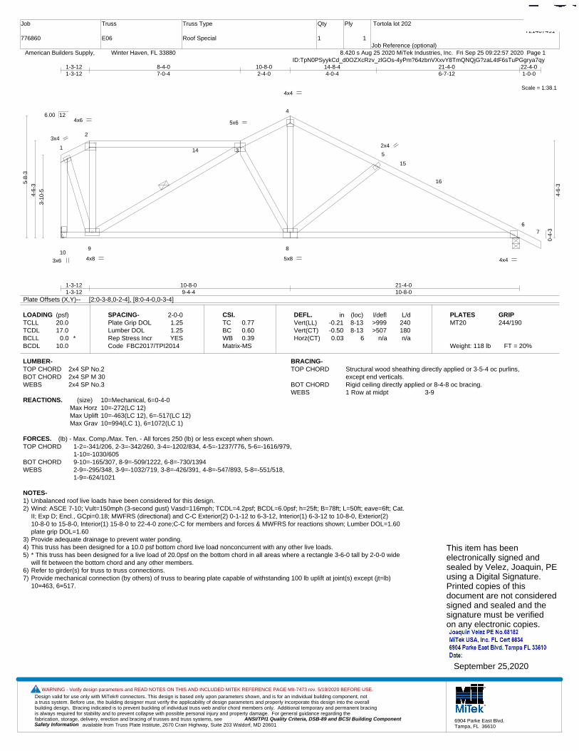
Design valid for use only with MiTek® connectors. This design is based only upon parameters shown, and is for an individual building component, not a truss system. Before use, the building designer must verify the applicability of design parameters and properly incorporate this design into the overall building design. Bracing indicated is to prevent buckling of individual truss web and/or chord members only. Additional temporary and permanent bracing is always required for stability and to prevent collapse with possible personal injury and property damage. For general guidance regarding the fabrication, storage, delivery, erection and bracing of trusses and truss systems, see ANSI/TPI1 Quality Criteria, DSB-89 and BCSI Building Component
available from Truss Plate Institute, 2670 Crain Highway, Suite 203 Waldorf, MD 20601Safety Information
WARNING - Verify design parameters and READ NOTES ON THIS AND INCLUDED MITEK REFERENCE PAGE MII-7473 rev. 5/19/2020 BEFORE USE.
6904 Parke East Blvd.Tampa, FL 36610
Job
776860
Truss
E06
Truss Type
Roof Special
Qty
1
Ply
1
Tortola lot 202
Job Reference (optional)
T21407491
8.420 s Aug 25 2020 MiTek Industries, Inc. Fri Sep 25 09:22:57 2020 Page 1 American Builders Supply, Winter Haven, FL 33880ID:TpN0PSyykCd_d0OZXcRzv_zlGOs-4yPm?64zbnVXxvY8TmQNQjG?zaL4tF6sTuPGgrya7qy
Scale = 1:38.1
1
2
3
4
5
67
109 8
14
15
16
4x6 5x6
4x4
3x6 4x8 5x8
2x4 3x4
4x4
1-3-121-3-12
10-8-09-4-4
21-4-010-8-0
1-3-121-3-12
8-4-07-0-4
10-8-02-4-0
14-8-44-0-4
21-4-06-7-12
22-4-01-0-0
3-10
-54-6-
35-8-
3
0-4-
3
4-6-
3
6.00 12
Plate Offsets (X,Y)-- [2:0-3-8,0-2-4], [8:0-4-0,0-3-4]
LOADING (psf)TCLLTCDLBCLLBCDL
20.017.0
0.0 *10.0
SPACING-Plate Grip DOLLumber DOL Rep Stress IncrCode
2-0-01.251.25YES
FBC2017/TPI2014
CSI.TCBCWBMatrix-MS
0.770.600.39
DEFL.Vert(LL)Vert(CT)Horz(CT)
in-0.21-0.500.03
(loc)8-138-13
6
l/defl>999>507
n/a
L/d240180n/a
PLATESMT20
Weight: 118 lb FT = 20%
GRIP244/190
LUMBER-TOP CHORD 2x4 SP No.2BOT CHORD 2x4 SP M 30WEBS 2x4 SP No.3
BRACING-TOP CHORD Structural wood sheathing directly applied or 3-5-4 oc purlins,
except end verticals.BOT CHORD Rigid ceiling directly applied or 8-4-8 oc bracing.WEBS 1 Row at midpt 3-9
REACTIONS. (size) 10=Mechanical, 6=0-4-0Max Horz 10=-272(LC 12)Max Uplift 10=-463(LC 12), 6=-517(LC 12)Max Grav 10=994(LC 1), 6=1072(LC 1)
FORCES. (lb) - Max. Comp./Max. Ten. - All forces 250 (lb) or less except when shown.TOP CHORD 1-2=-341/206, 2-3=-342/260, 3-4=-1202/834, 4-5=-1237/776, 5-6=-1616/979,
1-10=-1030/605BOT CHORD 9-10=-165/307, 8-9=-509/1222, 6-8=-730/1394WEBS 2-9=-295/348, 3-9=-1032/719, 3-8=-426/391, 4-8=-547/893, 5-8=-551/518,
1-9=-624/1021
NOTES-1) Unbalanced roof live loads have been considered for this design.2) Wind: ASCE 7-10; Vult=150mph (3-second gust) Vasd=116mph; TCDL=4.2psf; BCDL=6.0psf; h=25ft; B=78ft; L=50ft; eave=6ft; Cat.
II; Exp D; Encl., GCpi=0.18; MWFRS (directional) and C-C Exterior(2) 0-1-12 to 6-3-12, Interior(1) 6-3-12 to 10-8-0, Exterior(2)10-8-0 to 15-8-0, Interior(1) 15-8-0 to 22-4-0 zone;C-C for members and forces & MWFRS for reactions shown; Lumber DOL=1.60plate grip DOL=1.60
3) Provide adequate drainage to prevent water ponding.4) This truss has been designed for a 10.0 psf bottom chord live load nonconcurrent with any other live loads.5) * This truss has been designed for a live load of 20.0psf on the bottom chord in all areas where a rectangle 3-6-0 tall by 2-0-0 wide
will fit between the bottom chord and any other members.6) Refer to girder(s) for truss to truss connections.7) Provide mechanical connection (by others) of truss to bearing plate capable of withstanding 100 lb uplift at joint(s) except (jt=lb)
10=463, 6=517.
This item has beenelectronically signed andsealed by Velez, Joaquin, PEusing a Digital Signature.Printed copies of thisdocument are not consideredsigned and sealed and thesignature must be verified on any electronic copies.
September 25,2020
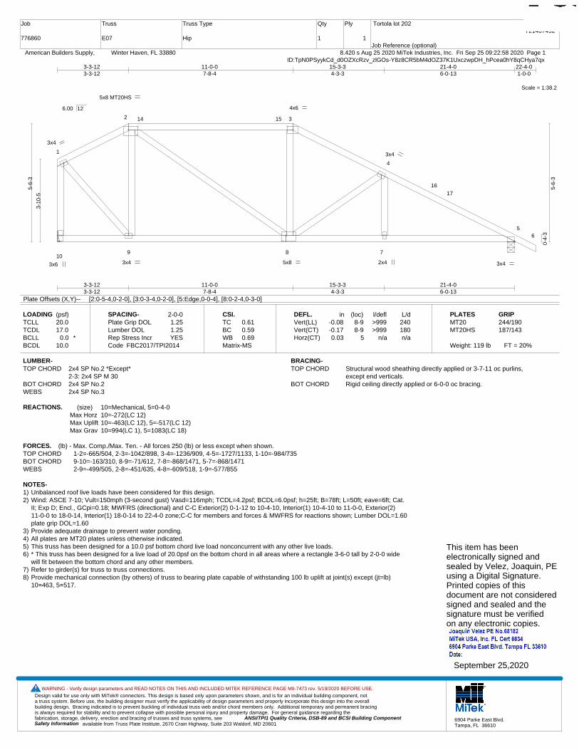
Design valid for use only with MiTek® connectors. This design is based only upon parameters shown, and is for an individual building component, not a truss system. Before use, the building designer must verify the applicability of design parameters and properly incorporate this design into the overall building design. Bracing indicated is to prevent buckling of individual truss web and/or chord members only. Additional temporary and permanent bracing is always required for stability and to prevent collapse with possible personal injury and property damage. For general guidance regarding the fabrication, storage, delivery, erection and bracing of trusses and truss systems, see ANSI/TPI1 Quality Criteria, DSB-89 and BCSI Building Component
available from Truss Plate Institute, 2670 Crain Highway, Suite 203 Waldorf, MD 20601Safety Information
WARNING - Verify design parameters and READ NOTES ON THIS AND INCLUDED MITEK REFERENCE PAGE MII-7473 rev. 5/19/2020 BEFORE USE.
6904 Parke East Blvd.Tampa, FL 36610
Job
776860
Truss
E07
Truss Type
Hip
Qty
1
Ply
1
Tortola lot 202
Job Reference (optional)
T21407492
8.420 s Aug 25 2020 MiTek Industries, Inc. Fri Sep 25 09:22:58 2020 Page 1 American Builders Supply, Winter Haven, FL 33880ID:TpN0PSyykCd_d0OZXcRzv_zlGOs-Y8z8CR5bM4dOZ37K1UxczwpDH_hPcea0hY8qCHya7qx
Scale = 1:38.2
1
2 3
4
56
109 8 7
14 15
16
17
5x8 MT20HS
4x6
3x6 3x4 5x8
3x4
2x4
3x4
3x4
3-3-123-3-12
11-0-07-8-4
15-3-34-3-3
21-4-06-0-13
3-3-123-3-12
11-0-07-8-4
15-3-34-3-3
21-4-06-0-13
22-4-01-0-0
3-10
-5
5-6-
3
0-4-
3
5-6-
3
6.00 12
Plate Offsets (X,Y)-- [2:0-5-4,0-2-0], [3:0-3-4,0-2-0], [5:Edge,0-0-4], [8:0-2-4,0-3-0]
LOADING (psf)TCLLTCDLBCLLBCDL
20.017.0
0.0 *10.0
SPACING-Plate Grip DOLLumber DOL Rep Stress IncrCode
2-0-01.251.25YES
FBC2017/TPI2014
CSI.TCBCWBMatrix-MS
0.610.590.69
DEFL.Vert(LL)Vert(CT)Horz(CT)
in-0.08-0.170.03
(loc)8-98-9
5
l/defl>999>999
n/a
L/d240180n/a
PLATESMT20MT20HS
Weight: 119 lb FT = 20%
GRIP244/190187/143
LUMBER-TOP CHORD 2x4 SP No.2 *Except*
2-3: 2x4 SP M 30BOT CHORD 2x4 SP No.2WEBS 2x4 SP No.3
BRACING-TOP CHORD Structural wood sheathing directly applied or 3-7-11 oc purlins,
except end verticals.BOT CHORD Rigid ceiling directly applied or 6-0-0 oc bracing.
REACTIONS. (size) 10=Mechanical, 5=0-4-0Max Horz 10=-272(LC 12)Max Uplift 10=-463(LC 12), 5=-517(LC 12)Max Grav 10=994(LC 1), 5=1083(LC 18)
FORCES. (lb) - Max. Comp./Max. Ten. - All forces 250 (lb) or less except when shown.TOP CHORD 1-2=-665/504, 2-3=-1042/898, 3-4=-1236/909, 4-5=-1727/1133, 1-10=-984/735BOT CHORD 9-10=-163/310, 8-9=-71/612, 7-8=-868/1471, 5-7=-868/1471WEBS 2-9=-499/505, 2-8=-451/635, 4-8=-609/518, 1-9=-577/855
NOTES-1) Unbalanced roof live loads have been considered for this design.2) Wind: ASCE 7-10; Vult=150mph (3-second gust) Vasd=116mph; TCDL=4.2psf; BCDL=6.0psf; h=25ft; B=78ft; L=50ft; eave=6ft; Cat.
II; Exp D; Encl., GCpi=0.18; MWFRS (directional) and C-C Exterior(2) 0-1-12 to 10-4-10, Interior(1) 10-4-10 to 11-0-0, Exterior(2)11-0-0 to 18-0-14, Interior(1) 18-0-14 to 22-4-0 zone;C-C for members and forces & MWFRS for reactions shown; Lumber DOL=1.60plate grip DOL=1.60
3) Provide adequate drainage to prevent water ponding.4) All plates are MT20 plates unless otherwise indicated. 5) This truss has been designed for a 10.0 psf bottom chord live load nonconcurrent with any other live loads.6) * This truss has been designed for a live load of 20.0psf on the bottom chord in all areas where a rectangle 3-6-0 tall by 2-0-0 wide
will fit between the bottom chord and any other members.7) Refer to girder(s) for truss to truss connections.8) Provide mechanical connection (by others) of truss to bearing plate capable of withstanding 100 lb uplift at joint(s) except (jt=lb)
10=463, 5=517.
This item has beenelectronically signed andsealed by Velez, Joaquin, PEusing a Digital Signature.Printed copies of thisdocument are not consideredsigned and sealed and thesignature must be verified on any electronic copies.
September 25,2020

Design valid for use only with MiTek® connectors. This design is based only upon parameters shown, and is for an individual building component, not a truss system. Before use, the building designer must verify the applicability of design parameters and properly incorporate this design into the overall building design. Bracing indicated is to prevent buckling of individual truss web and/or chord members only. Additional temporary and permanent bracing is always required for stability and to prevent collapse with possible personal injury and property damage. For general guidance regarding the fabrication, storage, delivery, erection and bracing of trusses and truss systems, see ANSI/TPI1 Quality Criteria, DSB-89 and BCSI Building Component
available from Truss Plate Institute, 2670 Crain Highway, Suite 203 Waldorf, MD 20601Safety Information
WARNING - Verify design parameters and READ NOTES ON THIS AND INCLUDED MITEK REFERENCE PAGE MII-7473 rev. 5/19/2020 BEFORE USE.
6904 Parke East Blvd.Tampa, FL 36610
Job
776860
Truss
E08
Truss Type
Hip
Qty
1
Ply
1
Tortola lot 202
Job Reference (optional)
T21407493
8.420 s Aug 25 2020 MiTek Industries, Inc. Fri Sep 25 09:22:58 2020 Page 1 American Builders Supply, Winter Haven, FL 33880ID:TpN0PSyykCd_d0OZXcRzv_zlGOs-Y8z8CR5bM4dOZ37K1UxczwpC5_f9cfQ0hY8qCHya7qx
Scale = 1:40.1
1
2 3
4
56
109
87
14
15
16 17
3x4
5x6 4x4
3x4 3x8
3x4
2x4 6x6 4x4
9-0-09-0-0
14-0-125-0-12
21-4-07-3-4
5-3-125-3-12
9-0-03-8-4
14-0-125-0-12
21-4-07-3-4
22-4-01-0-0
3-10
-5
6-6-
3
0-4-
3
6-6-
3
6.00 12
Plate Offsets (X,Y)-- [2:0-3-0,0-2-0]
LOADING (psf)TCLLTCDLBCLLBCDL
20.017.0
0.0 *10.0
SPACING-Plate Grip DOLLumber DOL Rep Stress IncrCode
2-0-01.251.25YES
FBC2017/TPI2014
CSI.TCBCWBMatrix-MS
0.680.740.58
DEFL.Vert(LL)Vert(CT)Horz(CT)
in-0.19-0.370.03
(loc)9-109-10
5
l/defl>999>691
n/a
L/d240180n/a
PLATESMT20
Weight: 118 lb FT = 20%
GRIP244/190
LUMBER-TOP CHORD 2x4 SP No.2BOT CHORD 2x4 SP No.2WEBS 2x4 SP No.3
BRACING-TOP CHORD Structural wood sheathing directly applied or 3-3-10 oc purlins,
except end verticals.BOT CHORD Rigid ceiling directly applied or 6-2-0 oc bracing.WEBS 1 Row at midpt 2-10
REACTIONS. (size) 10=Mechanical, 5=0-4-0Max Horz 10=-272(LC 12)Max Uplift 10=-463(LC 12), 5=-517(LC 12)Max Grav 10=994(LC 1), 5=1103(LC 18)
FORCES. (lb) - Max. Comp./Max. Ten. - All forces 250 (lb) or less except when shown.TOP CHORD 2-3=-881/793, 3-4=-1056/790, 4-5=-1671/1062, 1-10=-248/280BOT CHORD 9-10=-157/705, 7-9=-792/1398, 5-7=-792/1398WEBS 2-9=-231/563, 4-9=-759/639, 2-10=-942/655
NOTES-1) Unbalanced roof live loads have been considered for this design.2) Wind: ASCE 7-10; Vult=150mph (3-second gust) Vasd=116mph; TCDL=4.2psf; BCDL=6.0psf; h=25ft; B=78ft; L=50ft; eave=6ft; Cat.
II; Exp D; Encl., GCpi=0.18; MWFRS (directional) and C-C Exterior(2) 0-1-12 to 16-0-14, Interior(1) 16-0-14 to 22-4-0 zone;C-C formembers and forces & MWFRS for reactions shown; Lumber DOL=1.60 plate grip DOL=1.60
3) Provide adequate drainage to prevent water ponding.4) This truss has been designed for a 10.0 psf bottom chord live load nonconcurrent with any other live loads.5) * This truss has been designed for a live load of 20.0psf on the bottom chord in all areas where a rectangle 3-6-0 tall by 2-0-0 wide
will fit between the bottom chord and any other members, with BCDL = 10.0psf.6) Refer to girder(s) for truss to truss connections.7) Provide mechanical connection (by others) of truss to bearing plate capable of withstanding 100 lb uplift at joint(s) except (jt=lb)
10=463, 5=517.
This item has beenelectronically signed andsealed by Velez, Joaquin, PEusing a Digital Signature.Printed copies of thisdocument are not consideredsigned and sealed and thesignature must be verified on any electronic copies.
September 25,2020
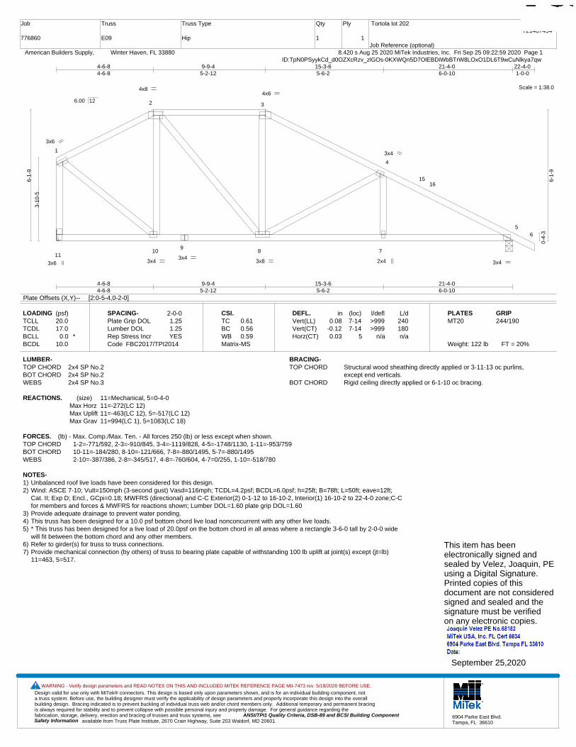
Design valid for use only with MiTek® connectors. This design is based only upon parameters shown, and is for an individual building component, not a truss system. Before use, the building designer must verify the applicability of design parameters and properly incorporate this design into the overall building design. Bracing indicated is to prevent buckling of individual truss web and/or chord members only. Additional temporary and permanent bracing is always required for stability and to prevent collapse with possible personal injury and property damage. For general guidance regarding the fabrication, storage, delivery, erection and bracing of trusses and truss systems, see ANSI/TPI1 Quality Criteria, DSB-89 and BCSI Building Component
available from Truss Plate Institute, 2670 Crain Highway, Suite 203 Waldorf, MD 20601Safety Information
WARNING - Verify design parameters and READ NOTES ON THIS AND INCLUDED MITEK REFERENCE PAGE MII-7473 rev. 5/19/2020 BEFORE USE.
6904 Parke East Blvd.Tampa, FL 36610
Job
776860
Truss
E09
Truss Type
Hip
Qty
1
Ply
1
Tortola lot 202
Job Reference (optional)
T21407494
8.420 s Aug 25 2020 MiTek Industries, Inc. Fri Sep 25 09:22:59 2020 Page 1 American Builders Supply, Winter Haven, FL 33880ID:TpN0PSyykCd_d0OZXcRzv_zlGOs-0KXWQn5D7OlEBDiWbBTrW8LOxO1DL6T9wCuNlkya7qw
Scale = 1:38.0
1
2 3
4
56
1110
98 7
1516
4x8 4x6
3x6 3x4
3x4 3x8
3x4
2x4
3x6
3x4
4-6-84-6-8
9-9-45-2-12
15-3-65-6-2
21-4-06-0-10
4-6-84-6-8
9-9-45-2-12
15-3-65-6-2
21-4-06-0-10
22-4-01-0-0
3-10
-5
6-1-
9
0-4-
3
6-1-
9
6.00 12
Plate Offsets (X,Y)-- [2:0-5-4,0-2-0]
LOADING (psf)TCLLTCDLBCLLBCDL
20.017.0
0.0 *10.0
SPACING-Plate Grip DOLLumber DOL Rep Stress IncrCode
2-0-01.251.25YES
FBC2017/TPI2014
CSI.TCBCWBMatrix-MS
0.610.560.59
DEFL.Vert(LL)Vert(CT)Horz(CT)
in0.08
-0.120.03
(loc)7-147-14
5
l/defl>999>999
n/a
L/d240180n/a
PLATESMT20
Weight: 122 lb FT = 20%
GRIP244/190
LUMBER-TOP CHORD 2x4 SP No.2BOT CHORD 2x4 SP No.2WEBS 2x4 SP No.3
BRACING-TOP CHORD Structural wood sheathing directly applied or 3-11-13 oc purlins,
except end verticals.BOT CHORD Rigid ceiling directly applied or 6-1-10 oc bracing.
REACTIONS. (size) 11=Mechanical, 5=0-4-0Max Horz 11=-272(LC 12)Max Uplift 11=-463(LC 12), 5=-517(LC 12)Max Grav 11=994(LC 1), 5=1083(LC 18)
FORCES. (lb) - Max. Comp./Max. Ten. - All forces 250 (lb) or less except when shown.TOP CHORD 1-2=-771/592, 2-3=-910/845, 3-4=-1119/828, 4-5=-1748/1130, 1-11=-953/759BOT CHORD 10-11=-184/280, 8-10=-121/666, 7-8=-880/1495, 5-7=-880/1495WEBS 2-10=-387/386, 2-8=-345/517, 4-8=-760/604, 4-7=0/255, 1-10=-518/780
NOTES-1) Unbalanced roof live loads have been considered for this design.2) Wind: ASCE 7-10; Vult=150mph (3-second gust) Vasd=116mph; TCDL=4.2psf; BCDL=6.0psf; h=25ft; B=78ft; L=50ft; eave=12ft;
Cat. II; Exp D; Encl., GCpi=0.18; MWFRS (directional) and C-C Exterior(2) 0-1-12 to 16-10-2, Interior(1) 16-10-2 to 22-4-0 zone;C-Cfor members and forces & MWFRS for reactions shown; Lumber DOL=1.60 plate grip DOL=1.60
3) Provide adequate drainage to prevent water ponding.4) This truss has been designed for a 10.0 psf bottom chord live load nonconcurrent with any other live loads.5) * This truss has been designed for a live load of 20.0psf on the bottom chord in all areas where a rectangle 3-6-0 tall by 2-0-0 wide
will fit between the bottom chord and any other members.6) Refer to girder(s) for truss to truss connections.7) Provide mechanical connection (by others) of truss to bearing plate capable of withstanding 100 lb uplift at joint(s) except (jt=lb)
11=463, 5=517.
This item has beenelectronically signed andsealed by Velez, Joaquin, PEusing a Digital Signature.Printed copies of thisdocument are not consideredsigned and sealed and thesignature must be verified on any electronic copies.
September 25,2020

Design valid for use only with MiTek® connectors. This design is based only upon parameters shown, and is for an individual building component, not a truss system. Before use, the building designer must verify the applicability of design parameters and properly incorporate this design into the overall building design. Bracing indicated is to prevent buckling of individual truss web and/or chord members only. Additional temporary and permanent bracing is always required for stability and to prevent collapse with possible personal injury and property damage. For general guidance regarding the fabrication, storage, delivery, erection and bracing of trusses and truss systems, see ANSI/TPI1 Quality Criteria, DSB-89 and BCSI Building Component
available from Truss Plate Institute, 2670 Crain Highway, Suite 203 Waldorf, MD 20601Safety Information
WARNING - Verify design parameters and READ NOTES ON THIS AND INCLUDED MITEK REFERENCE PAGE MII-7473 rev. 5/19/2020 BEFORE USE.
6904 Parke East Blvd.Tampa, FL 36610
Job
776860
Truss
E10
Truss Type
Hip
Qty
1
Ply
1
Tortola lot 202
Job Reference (optional)
T21407495
8.420 s Aug 25 2020 MiTek Industries, Inc. Fri Sep 25 09:23:00 2020 Page 1 American Builders Supply, Winter Haven, FL 33880ID:TpN0PSyykCd_d0OZXcRzv_zlGOs-UX5ud76suit5oMHj9v_42LuamnMZ4cjJ9sdwHAya7qv
Scale = 1:34.9
12 3
4
5
6
10
98 7
14 15
16
17
4x6 4x6
3x6 3x4
4x12
3x4
2x4
3x4
3x4
8-5-128-5-12
13-4-104-10-14
18-10-05-5-6
0-10-00-10-0
8-5-127-7-12
13-4-104-10-14
18-10-05-5-6
19-10-01-0-0
5-1-
5
5-6-
5
0-4-
3
5-6-
5
6.00 12
Plate Offsets (X,Y)-- [2:0-3-8,0-2-4], [3:0-3-4,0-2-0], [8:0-5-8,0-2-0]
LOADING (psf)TCLLTCDLBCLLBCDL
20.017.0
0.0 *10.0
SPACING-Plate Grip DOLLumber DOL Rep Stress IncrCode
2-0-01.251.25YES
FBC2017/TPI2014
CSI.TCBCWBMatrix-MS
0.550.610.40
DEFL.Vert(LL)Vert(CT)Horz(CT)
in-0.12-0.240.02
(loc)8-108-10
5
l/defl>999>924
n/a
L/d240180n/a
PLATESMT20
Weight: 113 lb FT = 20%
GRIP244/190
LUMBER-TOP CHORD 2x4 SP No.2 *Except*
2-3: 2x4 SP M 30BOT CHORD 2x4 SP No.2WEBS 2x4 SP No.3
BRACING-TOP CHORD Structural wood sheathing directly applied or 4-4-7 oc purlins,
except end verticals.BOT CHORD Rigid ceiling directly applied or 6-10-9 oc bracing.WEBS 1 Row at midpt 2-8, 1-8
REACTIONS. (size) 10=0-4-0, 5=0-4-0Max Horz 10=-350(LC 12)Max Uplift 10=-430(LC 12), 5=-444(LC 12)Max Grav 10=876(LC 1), 5=977(LC 18)
FORCES. (lb) - Max. Comp./Max. Ten. - All forces 250 (lb) or less except when shown.TOP CHORD 1-2=-913/818, 2-3=-809/652, 3-4=-975/633, 4-5=-1529/922, 1-10=-803/707BOT CHORD 8-10=-147/426, 7-8=-698/1290, 5-7=-698/1290WEBS 2-8=-225/304, 4-8=-641/549, 1-8=-947/1028
NOTES-1) Unbalanced roof live loads have been considered for this design.2) Wind: ASCE 7-10; Vult=150mph (3-second gust) Vasd=116mph; TCDL=4.2psf; BCDL=6.0psf; h=25ft; B=78ft; L=50ft; eave=10ft;
Cat. II; Exp D; Encl., GCpi=0.18; MWFRS (directional) and C-C Exterior(2) 0-1-12 to 7-10-14, Interior(1) 7-10-14 to 8-5-12,Exterior(2) 8-5-12 to 15-6-10, Interior(1) 15-6-10 to 19-10-0 zone;C-C for members and forces & MWFRS for reactions shown;Lumber DOL=1.60 plate grip DOL=1.60
3) Provide adequate drainage to prevent water ponding.4) This truss has been designed for a 10.0 psf bottom chord live load nonconcurrent with any other live loads.5) * This truss has been designed for a live load of 20.0psf on the bottom chord in all areas where a rectangle 3-6-0 tall by 2-0-0 wide
will fit between the bottom chord and any other members.6) Provide mechanical connection (by others) of truss to bearing plate capable of withstanding 100 lb uplift at joint(s) except (jt=lb)
10=430, 5=444.
This item has beenelectronically signed andsealed by Velez, Joaquin, PEusing a Digital Signature.Printed copies of thisdocument are not consideredsigned and sealed and thesignature must be verified on any electronic copies.
September 25,2020
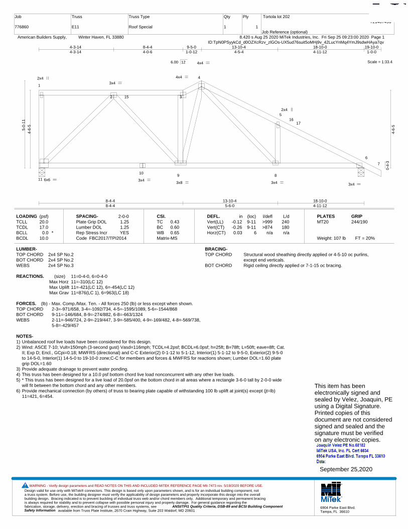
Design valid for use only with MiTek® connectors. This design is based only upon parameters shown, and is for an individual building component, not a truss system. Before use, the building designer must verify the applicability of design parameters and properly incorporate this design into the overall building design. Bracing indicated is to prevent buckling of individual truss web and/or chord members only. Additional temporary and permanent bracing is always required for stability and to prevent collapse with possible personal injury and property damage. For general guidance regarding the fabrication, storage, delivery, erection and bracing of trusses and truss systems, see ANSI/TPI1 Quality Criteria, DSB-89 and BCSI Building Component
available from Truss Plate Institute, 2670 Crain Highway, Suite 203 Waldorf, MD 20601Safety Information
WARNING - Verify design parameters and READ NOTES ON THIS AND INCLUDED MITEK REFERENCE PAGE MII-7473 rev. 5/19/2020 BEFORE USE.
6904 Parke East Blvd.Tampa, FL 36610
Job
776860
Truss
E11
Truss Type
Roof Special
Qty
1
Ply
1
Tortola lot 202
Job Reference (optional)
T21407496
8.420 s Aug 25 2020 MiTek Industries, Inc. Fri Sep 25 09:23:00 2020 Page 1 American Builders Supply, Winter Haven, FL 33880ID:TpN0PSyykCd_d0OZXcRzv_zlGOs-UX5ud76suit5oMHj9v_42LucYnMq4YmJ9sdwHAya7qv
Scale = 1:33.4
1
2 3
4
5
6
7
11
109 8
15
1617
6x6
2x4 4x4
4x4
3x4
3x4
3x8 3x4
2x4
3x4
8-4-48-4-4
13-10-45-6-0
18-10-04-11-12
4-3-144-3-14
8-4-44-0-6
9-5-01-0-12
13-10-44-5-4
18-10-04-11-12
19-10-01-0-0
4-6-
5
5-0-
11
0-4-
3
4-6-
5
6.00 12
LOADING (psf)TCLLTCDLBCLLBCDL
20.017.0
0.0 *10.0
SPACING-Plate Grip DOLLumber DOL Rep Stress IncrCode
2-0-01.251.25YES
FBC2017/TPI2014
CSI.TCBCWBMatrix-MS
0.430.600.65
DEFL.Vert(LL)Vert(CT)Horz(CT)
in-0.12-0.260.03
(loc)9-119-11
6
l/defl>999>874
n/a
L/d240180n/a
PLATESMT20
Weight: 107 lb FT = 20%
GRIP244/190
LUMBER-TOP CHORD 2x4 SP No.2BOT CHORD 2x4 SP No.2WEBS 2x4 SP No.3
BRACING-TOP CHORD Structural wood sheathing directly applied or 4-5-10 oc purlins,
except end verticals.BOT CHORD Rigid ceiling directly applied or 7-1-15 oc bracing.
REACTIONS. (size) 11=0-4-0, 6=0-4-0Max Horz 11=-310(LC 12)Max Uplift 11=-421(LC 12), 6=-454(LC 12)Max Grav 11=876(LC 1), 6=963(LC 18)
FORCES. (lb) - Max. Comp./Max. Ten. - All forces 250 (lb) or less except when shown.TOP CHORD 2-3=-971/658, 3-4=-1092/734, 4-5=-1595/1089, 5-6=-1544/868BOT CHORD 9-11=-146/684, 8-9=-274/882, 6-8=-663/1324WEBS 2-11=-946/724, 2-9=-219/447, 3-9=-585/400, 4-9=-169/482, 4-8=-569/738,
5-8=-429/457
NOTES-1) Unbalanced roof live loads have been considered for this design.2) Wind: ASCE 7-10; Vult=150mph (3-second gust) Vasd=116mph; TCDL=4.2psf; BCDL=6.0psf; h=25ft; B=78ft; L=50ft; eave=8ft; Cat.
II; Exp D; Encl., GCpi=0.18; MWFRS (directional) and C-C Exterior(2) 0-1-12 to 5-1-12, Interior(1) 5-1-12 to 9-5-0, Exterior(2) 9-5-0to 14-5-0, Interior(1) 14-5-0 to 19-10-0 zone;C-C for members and forces & MWFRS for reactions shown; Lumber DOL=1.60 plategrip DOL=1.60
3) Provide adequate drainage to prevent water ponding.4) This truss has been designed for a 10.0 psf bottom chord live load nonconcurrent with any other live loads.5) * This truss has been designed for a live load of 20.0psf on the bottom chord in all areas where a rectangle 3-6-0 tall by 2-0-0 wide
will fit between the bottom chord and any other members.6) Provide mechanical connection (by others) of truss to bearing plate capable of withstanding 100 lb uplift at joint(s) except (jt=lb)
11=421, 6=454.
This item has beenelectronically signed andsealed by Velez, Joaquin, PEusing a Digital Signature.Printed copies of thisdocument are not consideredsigned and sealed and thesignature must be verified on any electronic copies.
September 25,2020
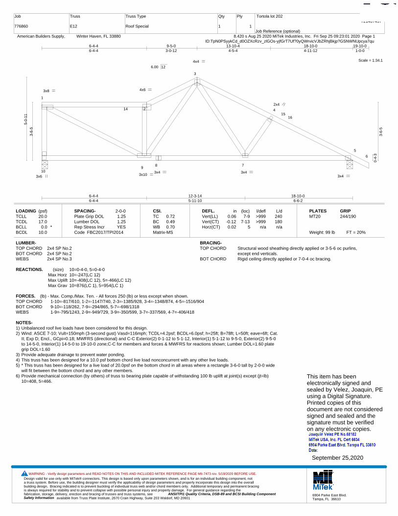
Design valid for use only with MiTek® connectors. This design is based only upon parameters shown, and is for an individual building component, not a truss system. Before use, the building designer must verify the applicability of design parameters and properly incorporate this design into the overall building design. Bracing indicated is to prevent buckling of individual truss web and/or chord members only. Additional temporary and permanent bracing is always required for stability and to prevent collapse with possible personal injury and property damage. For general guidance regarding the fabrication, storage, delivery, erection and bracing of trusses and truss systems, see ANSI/TPI1 Quality Criteria, DSB-89 and BCSI Building Component
available from Truss Plate Institute, 2670 Crain Highway, Suite 203 Waldorf, MD 20601Safety Information
WARNING - Verify design parameters and READ NOTES ON THIS AND INCLUDED MITEK REFERENCE PAGE MII-7473 rev. 5/19/2020 BEFORE USE.
6904 Parke East Blvd.Tampa, FL 36610
Job
776860
Truss
E12
Truss Type
Roof Special
Qty
1
Ply
1
Tortola lot 202
Job Reference (optional)
T21407497
8.420 s Aug 25 2020 MiTek Industries, Inc. Fri Sep 25 09:23:01 2020 Page 1 American Builders Supply, Winter Haven, FL 33880ID:TpN0PSyykCd_d0OZXcRzv_zlGOs-yjfGrT7Uf?0yQWrvicVJbZRhjBkjp?GSNWNUpcya7qu
Scale = 1:34.1
1
2
3
4
5
6
109
8 7
1415
16
3x6
3x8 4x6
4x4
3x4 3x10
3x4
2x4
3x4
6-4-46-4-4
12-3-145-11-10
18-10-06-6-2
6-4-46-4-4
9-5-03-0-12
13-10-44-5-4
18-10-04-11-12
19-10-01-0-0
3-6-
5
5-0-
11
0-4-
3
3-6-
5
6.00 12
LOADING (psf)TCLLTCDLBCLLBCDL
20.017.0
0.0 *10.0
SPACING-Plate Grip DOLLumber DOL Rep Stress IncrCode
2-0-01.251.25YES
FBC2017/TPI2014
CSI.TCBCWBMatrix-MS
0.720.490.70
DEFL.Vert(LL)Vert(CT)Horz(CT)
in0.06
-0.120.02
(loc)7-9
7-135
l/defl>999>999
n/a
L/d240180n/a
PLATESMT20
Weight: 99 lb FT = 20%
GRIP244/190
LUMBER-TOP CHORD 2x4 SP No.2BOT CHORD 2x4 SP No.2WEBS 2x4 SP No.3
BRACING-TOP CHORD Structural wood sheathing directly applied or 3-5-6 oc purlins,
except end verticals.BOT CHORD Rigid ceiling directly applied or 7-0-4 oc bracing.
REACTIONS. (size) 10=0-4-0, 5=0-4-0Max Horz 10=-247(LC 12)Max Uplift 10=-408(LC 12), 5=-466(LC 12)Max Grav 10=876(LC 1), 5=954(LC 1)
FORCES. (lb) - Max. Comp./Max. Ten. - All forces 250 (lb) or less except when shown.TOP CHORD 1-10=-817/610, 1-2=-1147/740, 2-3=-1385/928, 3-4=-1348/874, 4-5=-1516/904BOT CHORD 9-10=-118/262, 7-9=-294/865, 5-7=-698/1318WEBS 1-9=-795/1243, 2-9=-949/729, 3-9=-350/599, 3-7=-337/569, 4-7=-406/418
NOTES-1) Unbalanced roof live loads have been considered for this design.2) Wind: ASCE 7-10; Vult=150mph (3-second gust) Vasd=116mph; TCDL=4.2psf; BCDL=6.0psf; h=25ft; B=78ft; L=50ft; eave=6ft; Cat.
II; Exp D; Encl., GCpi=0.18; MWFRS (directional) and C-C Exterior(2) 0-1-12 to 5-1-12, Interior(1) 5-1-12 to 9-5-0, Exterior(2) 9-5-0to 14-5-0, Interior(1) 14-5-0 to 19-10-0 zone;C-C for members and forces & MWFRS for reactions shown; Lumber DOL=1.60 plategrip DOL=1.60
3) Provide adequate drainage to prevent water ponding.4) This truss has been designed for a 10.0 psf bottom chord live load nonconcurrent with any other live loads.5) * This truss has been designed for a live load of 20.0psf on the bottom chord in all areas where a rectangle 3-6-0 tall by 2-0-0 wide
will fit between the bottom chord and any other members.6) Provide mechanical connection (by others) of truss to bearing plate capable of withstanding 100 lb uplift at joint(s) except (jt=lb)
10=408, 5=466.This item has beenelectronically signed andsealed by Velez, Joaquin, PEusing a Digital Signature.Printed copies of thisdocument are not consideredsigned and sealed and thesignature must be verified on any electronic copies.
September 25,2020

Design valid for use only with MiTek® connectors. This design is based only upon parameters shown, and is for an individual building component, not a truss system. Before use, the building designer must verify the applicability of design parameters and properly incorporate this design into the overall building design. Bracing indicated is to prevent buckling of individual truss web and/or chord members only. Additional temporary and permanent bracing is always required for stability and to prevent collapse with possible personal injury and property damage. For general guidance regarding the fabrication, storage, delivery, erection and bracing of trusses and truss systems, see ANSI/TPI1 Quality Criteria, DSB-89 and BCSI Building Component
available from Truss Plate Institute, 2670 Crain Highway, Suite 203 Waldorf, MD 20601Safety Information
WARNING - Verify design parameters and READ NOTES ON THIS AND INCLUDED MITEK REFERENCE PAGE MII-7473 rev. 5/19/2020 BEFORE USE.
6904 Parke East Blvd.Tampa, FL 36610
Job
776860
Truss
EJ1
Truss Type
Jack-Open
Qty
11
Ply
1
Tortola lot 202
Job Reference (optional)
T21407498
8.420 s Aug 25 2020 MiTek Industries, Inc. Fri Sep 25 09:23:02 2020 Page 1 American Builders Supply, Winter Haven, FL 33880ID:TpN0PSyykCd_d0OZXcRzv_zlGOs-QvCf2p86QJ8p2gQ5GK0Y7mz_IbB2YcQbcA61L3ya7qt
Scale = 1:7.0
1
2
3
4
3x4
1-0-01-0-0
-1-0-01-0-0
1-0-01-0-0
0-4-
3
0-10
-3
0-5-
8
0-10
-3
6.00 12
LOADING (psf)TCLLTCDLBCLLBCDL
20.017.0
0.0 *10.0
SPACING-Plate Grip DOLLumber DOL Rep Stress IncrCode
2-0-01.251.25YES
FBC2017/TPI2014
CSI.TCBCWBMatrix-MP
0.220.040.00
DEFL.Vert(LL)Vert(CT)Horz(CT)
in-0.000.000.00
(loc)752
l/defl>999>999
n/a
L/d240180n/a
PLATESMT20
Weight: 5 lb FT = 20%
GRIP244/190
LUMBER-TOP CHORD 2x4 SP No.2BOT CHORD 2x4 SP No.2
BRACING-TOP CHORD Structural wood sheathing directly applied or 1-0-0 oc purlins.BOT CHORD Rigid ceiling directly applied or 10-0-0 oc bracing.
REACTIONS. (size) 3=Mechanical, 2=0-8-0, 4=MechanicalMax Horz 2=79(LC 12)Max Uplift 3=-8(LC 9), 2=-153(LC 12), 4=-2(LC 1)Max Grav 3=15(LC 17), 2=158(LC 1), 4=23(LC 12)
FORCES. (lb) - Max. Comp./Max. Ten. - All forces 250 (lb) or less except when shown.
NOTES-1) Wind: ASCE 7-10; Vult=150mph (3-second gust) Vasd=116mph; TCDL=4.2psf; BCDL=6.0psf; h=25ft; B=78ft; L=50ft; eave=1ft; Cat.
II; Exp D; Encl., GCpi=0.18; MWFRS (directional) and C-C Corner(3) zone;C-C for members and forces & MWFRS for reactionsshown; Lumber DOL=1.60 plate grip DOL=1.60
2) This truss has been designed for a 10.0 psf bottom chord live load nonconcurrent with any other live loads.3) * This truss has been designed for a live load of 20.0psf on the bottom chord in all areas where a rectangle 3-6-0 tall by 2-0-0 wide
will fit between the bottom chord and any other members.4) Refer to girder(s) for truss to truss connections.5) Provide mechanical connection (by others) of truss to bearing plate capable of withstanding 100 lb uplift at joint(s) 3, 4 except (jt=lb)
2=153.
This item has beenelectronically signed andsealed by Velez, Joaquin, PEusing a Digital Signature.Printed copies of thisdocument are not consideredsigned and sealed and thesignature must be verified on any electronic copies.
September 25,2020

Design valid for use only with MiTek® connectors. This design is based only upon parameters shown, and is for an individual building component, not a truss system. Before use, the building designer must verify the applicability of design parameters and properly incorporate this design into the overall building design. Bracing indicated is to prevent buckling of individual truss web and/or chord members only. Additional temporary and permanent bracing is always required for stability and to prevent collapse with possible personal injury and property damage. For general guidance regarding the fabrication, storage, delivery, erection and bracing of trusses and truss systems, see ANSI/TPI1 Quality Criteria, DSB-89 and BCSI Building Component
available from Truss Plate Institute, 2670 Crain Highway, Suite 203 Waldorf, MD 20601Safety Information
WARNING - Verify design parameters and READ NOTES ON THIS AND INCLUDED MITEK REFERENCE PAGE MII-7473 rev. 5/19/2020 BEFORE USE.
6904 Parke East Blvd.Tampa, FL 36610
Job
776860
Truss
EJ2
Truss Type
Jack-Open
Qty
3
Ply
1
Tortola lot 202
Job Reference (optional)
T21407499
8.420 s Aug 25 2020 MiTek Industries, Inc. Fri Sep 25 09:23:02 2020 Page 1 American Builders Supply, Winter Haven, FL 33880ID:TpN0PSyykCd_d0OZXcRzv_zlGOs-QvCf2p86QJ8p2gQ5GK0Y7mz_IbB2YcQbcA61L3ya7qt
Scale = 1:8.7
1
2
3
4
3x4
1-8-01-8-0
-1-0-01-0-0
1-8-01-8-0
0-4-
3
1-2-
3
0-9-
8
1-2-
3
6.00 12
LOADING (psf)TCLLTCDLBCLLBCDL
20.017.0
0.0 *10.0
SPACING-Plate Grip DOLLumber DOL Rep Stress IncrCode
2-0-01.251.25YES
FBC2017/TPI2014
CSI.TCBCWBMatrix-MP
0.220.040.00
DEFL.Vert(LL)Vert(CT)Horz(CT)
in-0.00-0.00-0.00
(loc)773
l/defl>999>999
n/a
L/d240180n/a
PLATESMT20
Weight: 7 lb FT = 20%
GRIP244/190
LUMBER-TOP CHORD 2x4 SP No.2BOT CHORD 2x4 SP No.2
BRACING-TOP CHORD Structural wood sheathing directly applied or 1-8-0 oc purlins.BOT CHORD Rigid ceiling directly applied or 10-0-0 oc bracing.
REACTIONS. (size) 3=Mechanical, 2=0-8-0, 4=MechanicalMax Horz 2=99(LC 12)Max Uplift 3=-27(LC 12), 2=-140(LC 12)Max Grav 3=47(LC 17), 2=175(LC 17), 4=27(LC 3)
FORCES. (lb) - Max. Comp./Max. Ten. - All forces 250 (lb) or less except when shown.
NOTES-1) Wind: ASCE 7-10; Vult=150mph (3-second gust) Vasd=116mph; TCDL=4.2psf; BCDL=6.0psf; h=25ft; B=78ft; L=50ft; eave=2ft; Cat.
II; Exp D; Encl., GCpi=0.18; MWFRS (directional) and C-C Corner(3) zone;C-C for members and forces & MWFRS for reactionsshown; Lumber DOL=1.60 plate grip DOL=1.60
2) This truss has been designed for a 10.0 psf bottom chord live load nonconcurrent with any other live loads.3) * This truss has been designed for a live load of 20.0psf on the bottom chord in all areas where a rectangle 3-6-0 tall by 2-0-0 wide
will fit between the bottom chord and any other members.4) Refer to girder(s) for truss to truss connections.5) Provide mechanical connection (by others) of truss to bearing plate capable of withstanding 100 lb uplift at joint(s) 3 except (jt=lb)
2=140.
This item has beenelectronically signed andsealed by Velez, Joaquin, PEusing a Digital Signature.Printed copies of thisdocument are not consideredsigned and sealed and thesignature must be verified on any electronic copies.
September 25,2020

Design valid for use only with MiTek® connectors. This design is based only upon parameters shown, and is for an individual building component, not a truss system. Before use, the building designer must verify the applicability of design parameters and properly incorporate this design into the overall building design. Bracing indicated is to prevent buckling of individual truss web and/or chord members only. Additional temporary and permanent bracing is always required for stability and to prevent collapse with possible personal injury and property damage. For general guidance regarding the fabrication, storage, delivery, erection and bracing of trusses and truss systems, see ANSI/TPI1 Quality Criteria, DSB-89 and BCSI Building Component
available from Truss Plate Institute, 2670 Crain Highway, Suite 203 Waldorf, MD 20601Safety Information
WARNING - Verify design parameters and READ NOTES ON THIS AND INCLUDED MITEK REFERENCE PAGE MII-7473 rev. 5/19/2020 BEFORE USE.
6904 Parke East Blvd.Tampa, FL 36610
Job
776860
Truss
EJ2H
Truss Type
Jack-Open
Qty
1
Ply
1
Tortola lot 202
Job Reference (optional)
T21407500
8.420 s Aug 25 2020 MiTek Industries, Inc. Fri Sep 25 09:23:03 2020 Page 1 American Builders Supply, Winter Haven, FL 33880ID:TpN0PSyykCd_d0OZXcRzv_zlGOs-u6m1F99kBdGgfq?Iq1Xng_WCt?X1H3flrpsbuVya7qs
Scale = 1:8.7
1
2
3
2x4
1-8-01-8-0
1-8-01-8-0
0-4-
3
1-2-
3
0-9-
8
1-2-
3
6.00 12
LOADING (psf)TCLLTCDLBCLLBCDL
20.017.0
0.0 *10.0
SPACING-Plate Grip DOLLumber DOL Rep Stress IncrCode
2-0-01.251.25YES
FBC2017/TPI2014
CSI.TCBCWBMatrix-MP
0.040.050.00
DEFL.Vert(LL)Vert(CT)Horz(CT)
in-0.00-0.00-0.00
(loc)662
l/defl>999>999
n/a
L/d240180n/a
PLATESMT20
Weight: 5 lb FT = 20%
GRIP244/190
LUMBER-TOP CHORD 2x4 SP No.2BOT CHORD 2x4 SP No.2
BRACING-TOP CHORD Structural wood sheathing directly applied or 1-8-0 oc purlins.BOT CHORD Rigid ceiling directly applied or 10-0-0 oc bracing.
REACTIONS. (size) 1=0-8-0, 2=Mechanical, 3=MechanicalMax Horz 1=52(LC 12)Max Uplift 1=-21(LC 12), 2=-42(LC 12), 3=-7(LC 12)Max Grav 1=80(LC 17), 2=57(LC 17), 3=33(LC 3)
FORCES. (lb) - Max. Comp./Max. Ten. - All forces 250 (lb) or less except when shown.
NOTES-1) Wind: ASCE 7-10; Vult=150mph (3-second gust) Vasd=116mph; TCDL=4.2psf; BCDL=6.0psf; h=25ft; B=78ft; L=50ft; eave=6ft; Cat.
II; Exp D; Encl., GCpi=0.18; MWFRS (directional) and C-C Exterior(2) zone;C-C for members and forces & MWFRS for reactionsshown; Lumber DOL=1.60 plate grip DOL=1.60
2) This truss has been designed for a 10.0 psf bottom chord live load nonconcurrent with any other live loads.3) * This truss has been designed for a live load of 20.0psf on the bottom chord in all areas where a rectangle 3-6-0 tall by 2-0-0 wide
will fit between the bottom chord and any other members.4) Refer to girder(s) for truss to truss connections.5) Provide mechanical connection (by others) of truss to bearing plate capable of withstanding 100 lb uplift at joint(s) 1, 2, 3.
This item has beenelectronically signed andsealed by Velez, Joaquin, PEusing a Digital Signature.Printed copies of thisdocument are not consideredsigned and sealed and thesignature must be verified on any electronic copies.
September 25,2020
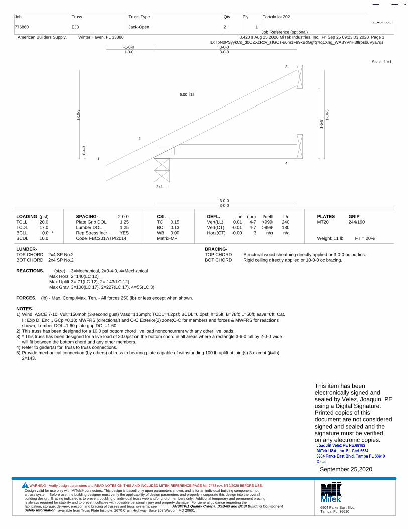
Design valid for use only with MiTek® connectors. This design is based only upon parameters shown, and is for an individual building component, not a truss system. Before use, the building designer must verify the applicability of design parameters and properly incorporate this design into the overall building design. Bracing indicated is to prevent buckling of individual truss web and/or chord members only. Additional temporary and permanent bracing is always required for stability and to prevent collapse with possible personal injury and property damage. For general guidance regarding the fabrication, storage, delivery, erection and bracing of trusses and truss systems, see ANSI/TPI1 Quality Criteria, DSB-89 and BCSI Building Component
available from Truss Plate Institute, 2670 Crain Highway, Suite 203 Waldorf, MD 20601Safety Information
WARNING - Verify design parameters and READ NOTES ON THIS AND INCLUDED MITEK REFERENCE PAGE MII-7473 rev. 5/19/2020 BEFORE USE.
6904 Parke East Blvd.Tampa, FL 36610
Job
776860
Truss
EJ3
Truss Type
Jack-Open
Qty
2
Ply
1
Tortola lot 202
Job Reference (optional)
T21407501
8.420 s Aug 25 2020 MiTek Industries, Inc. Fri Sep 25 09:23:03 2020 Page 1 American Builders Supply, Winter Haven, FL 33880ID:TpN0PSyykCd_d0OZXcRzv_zlGOs-u6m1F99kBdGgfq?Iq1Xng_WAB?VnH3flrpsbuVya7qs
Scale: 1"=1'
1
2
3
4
2x4
3-0-03-0-0
-1-0-01-0-0
3-0-03-0-0
0-4-
3
1-10
-3
1-5-
8 1-10
-3
6.00 12
LOADING (psf)TCLLTCDLBCLLBCDL
20.017.0
0.0 *10.0
SPACING-Plate Grip DOLLumber DOL Rep Stress IncrCode
2-0-01.251.25YES
FBC2017/TPI2014
CSI.TCBCWBMatrix-MP
0.150.130.00
DEFL.Vert(LL)Vert(CT)Horz(CT)
in0.01
-0.01-0.00
(loc)4-74-7
3
l/defl>999>999
n/a
L/d240180n/a
PLATESMT20
Weight: 11 lb FT = 20%
GRIP244/190
LUMBER-TOP CHORD 2x4 SP No.2BOT CHORD 2x4 SP No.2
BRACING-TOP CHORD Structural wood sheathing directly applied or 3-0-0 oc purlins.BOT CHORD Rigid ceiling directly applied or 10-0-0 oc bracing.
REACTIONS. (size) 3=Mechanical, 2=0-4-0, 4=MechanicalMax Horz 2=140(LC 12)Max Uplift 3=-71(LC 12), 2=-143(LC 12)Max Grav 3=100(LC 17), 2=227(LC 17), 4=55(LC 3)
FORCES. (lb) - Max. Comp./Max. Ten. - All forces 250 (lb) or less except when shown.
NOTES-1) Wind: ASCE 7-10; Vult=150mph (3-second gust) Vasd=116mph; TCDL=4.2psf; BCDL=6.0psf; h=25ft; B=78ft; L=50ft; eave=6ft; Cat.
II; Exp D; Encl., GCpi=0.18; MWFRS (directional) and C-C Exterior(2) zone;C-C for members and forces & MWFRS for reactionsshown; Lumber DOL=1.60 plate grip DOL=1.60
2) This truss has been designed for a 10.0 psf bottom chord live load nonconcurrent with any other live loads.3) * This truss has been designed for a live load of 20.0psf on the bottom chord in all areas where a rectangle 3-6-0 tall by 2-0-0 wide
will fit between the bottom chord and any other members.4) Refer to girder(s) for truss to truss connections.5) Provide mechanical connection (by others) of truss to bearing plate capable of withstanding 100 lb uplift at joint(s) 3 except (jt=lb)
2=143.
This item has beenelectronically signed andsealed by Velez, Joaquin, PEusing a Digital Signature.Printed copies of thisdocument are not consideredsigned and sealed and thesignature must be verified on any electronic copies.
September 25,2020

Design valid for use only with MiTek® connectors. This design is based only upon parameters shown, and is for an individual building component, not a truss system. Before use, the building designer must verify the applicability of design parameters and properly incorporate this design into the overall building design. Bracing indicated is to prevent buckling of individual truss web and/or chord members only. Additional temporary and permanent bracing is always required for stability and to prevent collapse with possible personal injury and property damage. For general guidance regarding the fabrication, storage, delivery, erection and bracing of trusses and truss systems, see ANSI/TPI1 Quality Criteria, DSB-89 and BCSI Building Component
available from Truss Plate Institute, 2670 Crain Highway, Suite 203 Waldorf, MD 20601Safety Information
WARNING - Verify design parameters and READ NOTES ON THIS AND INCLUDED MITEK REFERENCE PAGE MII-7473 rev. 5/19/2020 BEFORE USE.
6904 Parke East Blvd.Tampa, FL 36610
Job
776860
Truss
EJ5
Truss Type
Jack-Open
Qty
7
Ply
1
Tortola lot 202
Job Reference (optional)
T21407502
8.420 s Aug 25 2020 MiTek Industries, Inc. Fri Sep 25 09:23:04 2020 Page 1 American Builders Supply, Winter Haven, FL 33880ID:TpN0PSyykCd_d0OZXcRzv_zlGOs-MIKPTV9MywOXH_aUOk20DB3FLPmX0Wvu4Tb8Qxya7qr
Scale = 1:17.0
1
2
8
3
4
3x4
5-0-05-0-0
-1-0-01-0-0
5-0-05-0-0
0-4-
3
2-10
-3
2-5-
8 2-10
-3
6.00 12
LOADING (psf)TCLLTCDLBCLLBCDL
20.017.0
0.0 *10.0
SPACING-Plate Grip DOLLumber DOL Rep Stress IncrCode
2-0-01.251.25YES
FBC2017/TPI2014
CSI.TCBCWBMatrix-MP
0.570.480.00
DEFL.Vert(LL)Vert(CT)Horz(CT)
in0.07
-0.08-0.00
(loc)4-74-7
3
l/defl>833>790
n/a
L/d240180n/a
PLATESMT20
Weight: 18 lb FT = 20%
GRIP244/190
LUMBER-TOP CHORD 2x4 SP No.2BOT CHORD 2x4 SP No.2
BRACING-TOP CHORD Structural wood sheathing directly applied or 5-0-0 oc purlins.BOT CHORD Rigid ceiling directly applied or 10-0-0 oc bracing.
REACTIONS. (size) 3=Mechanical, 2=0-4-0, 4=MechanicalMax Horz 2=202(LC 12)Max Uplift 3=-134(LC 12), 2=-162(LC 12)Max Grav 3=180(LC 17), 2=319(LC 17), 4=96(LC 3)
FORCES. (lb) - Max. Comp./Max. Ten. - All forces 250 (lb) or less except when shown.
NOTES-1) Wind: ASCE 7-10; Vult=150mph (3-second gust) Vasd=116mph; TCDL=4.2psf; BCDL=6.0psf; h=25ft; B=78ft; L=50ft; eave=6ft; Cat.
II; Exp D; Encl., GCpi=0.18; MWFRS (directional) and C-C Exterior(2) -1-0-0 to 4-0-0, Interior(1) 4-0-0 to 4-11-4 zone;C-C formembers and forces & MWFRS for reactions shown; Lumber DOL=1.60 plate grip DOL=1.60
2) This truss has been designed for a 10.0 psf bottom chord live load nonconcurrent with any other live loads.3) * This truss has been designed for a live load of 20.0psf on the bottom chord in all areas where a rectangle 3-6-0 tall by 2-0-0 wide
will fit between the bottom chord and any other members.4) Refer to girder(s) for truss to truss connections.5) Provide mechanical connection (by others) of truss to bearing plate capable of withstanding 100 lb uplift at joint(s) except (jt=lb)
3=134, 2=162.
This item has beenelectronically signed andsealed by Velez, Joaquin, PEusing a Digital Signature.Printed copies of thisdocument are not consideredsigned and sealed and thesignature must be verified on any electronic copies.
September 25,2020
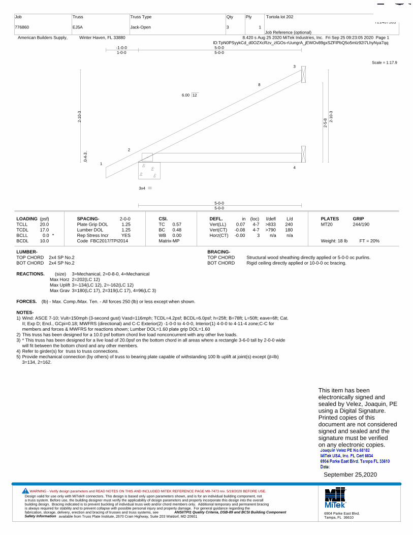
Design valid for use only with MiTek® connectors. This design is based only upon parameters shown, and is for an individual building component, not a truss system. Before use, the building designer must verify the applicability of design parameters and properly incorporate this design into the overall building design. Bracing indicated is to prevent buckling of individual truss web and/or chord members only. Additional temporary and permanent bracing is always required for stability and to prevent collapse with possible personal injury and property damage. For general guidance regarding the fabrication, storage, delivery, erection and bracing of trusses and truss systems, see ANSI/TPI1 Quality Criteria, DSB-89 and BCSI Building Component
available from Truss Plate Institute, 2670 Crain Highway, Suite 203 Waldorf, MD 20601Safety Information
WARNING - Verify design parameters and READ NOTES ON THIS AND INCLUDED MITEK REFERENCE PAGE MII-7473 rev. 5/19/2020 BEFORE USE.
6904 Parke East Blvd.Tampa, FL 36610
Job
776860
Truss
EJ5A
Truss Type
Jack-Open
Qty
3
Ply
1
Tortola lot 202
Job Reference (optional)
T21407503
8.420 s Aug 25 2020 MiTek Industries, Inc. Fri Sep 25 09:23:05 2020 Page 1 American Builders Supply, Winter Haven, FL 33880ID:TpN0PSyykCd_d0OZXcRzv_zlGOs-rUungrA_jEWOv89gxSZFlPbQ5o5mlz92I7LhyNya7qq
Scale = 1:17.9
1
2
8
3
4
3x4
5-0-05-0-0
-1-0-01-0-0
5-0-05-0-0
0-4-
3
2-10
-3
2-5-
8 2-10
-3
6.00 12
LOADING (psf)TCLLTCDLBCLLBCDL
20.017.0
0.0 *10.0
SPACING-Plate Grip DOLLumber DOL Rep Stress IncrCode
2-0-01.251.25YES
FBC2017/TPI2014
CSI.TCBCWBMatrix-MP
0.570.480.00
DEFL.Vert(LL)Vert(CT)Horz(CT)
in0.07
-0.08-0.00
(loc)4-74-7
3
l/defl>833>790
n/a
L/d240180n/a
PLATESMT20
Weight: 18 lb FT = 20%
GRIP244/190
LUMBER-TOP CHORD 2x4 SP No.2BOT CHORD 2x4 SP No.2
BRACING-TOP CHORD Structural wood sheathing directly applied or 5-0-0 oc purlins.BOT CHORD Rigid ceiling directly applied or 10-0-0 oc bracing.
REACTIONS. (size) 3=Mechanical, 2=0-8-0, 4=MechanicalMax Horz 2=202(LC 12)Max Uplift 3=-134(LC 12), 2=-162(LC 12)Max Grav 3=180(LC 17), 2=319(LC 17), 4=96(LC 3)
FORCES. (lb) - Max. Comp./Max. Ten. - All forces 250 (lb) or less except when shown.
NOTES-1) Wind: ASCE 7-10; Vult=150mph (3-second gust) Vasd=116mph; TCDL=4.2psf; BCDL=6.0psf; h=25ft; B=78ft; L=50ft; eave=6ft; Cat.
II; Exp D; Encl., GCpi=0.18; MWFRS (directional) and C-C Exterior(2) -1-0-0 to 4-0-0, Interior(1) 4-0-0 to 4-11-4 zone;C-C formembers and forces & MWFRS for reactions shown; Lumber DOL=1.60 plate grip DOL=1.60
2) This truss has been designed for a 10.0 psf bottom chord live load nonconcurrent with any other live loads.3) * This truss has been designed for a live load of 20.0psf on the bottom chord in all areas where a rectangle 3-6-0 tall by 2-0-0 wide
will fit between the bottom chord and any other members.4) Refer to girder(s) for truss to truss connections.5) Provide mechanical connection (by others) of truss to bearing plate capable of withstanding 100 lb uplift at joint(s) except (jt=lb)
3=134, 2=162.
This item has beenelectronically signed andsealed by Velez, Joaquin, PEusing a Digital Signature.Printed copies of thisdocument are not consideredsigned and sealed and thesignature must be verified on any electronic copies.
September 25,2020
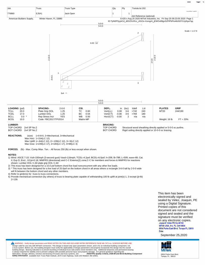
Design valid for use only with MiTek® connectors. This design is based only upon parameters shown, and is for an individual building component, not a truss system. Before use, the building designer must verify the applicability of design parameters and properly incorporate this design into the overall building design. Bracing indicated is to prevent buckling of individual truss web and/or chord members only. Additional temporary and permanent bracing is always required for stability and to prevent collapse with possible personal injury and property damage. For general guidance regarding the fabrication, storage, delivery, erection and bracing of trusses and truss systems, see ANSI/TPI1 Quality Criteria, DSB-89 and BCSI Building Component
available from Truss Plate Institute, 2670 Crain Highway, Suite 203 Waldorf, MD 20601Safety Information
WARNING - Verify design parameters and READ NOTES ON THIS AND INCLUDED MITEK REFERENCE PAGE MII-7473 rev. 5/19/2020 BEFORE USE.
6904 Parke East Blvd.Tampa, FL 36610
Job
776860
Truss
EJ5A1
Truss Type
Jack-Open
Qty
1
Ply
1
Tortola lot 202
Job Reference (optional)
T21407504
8.420 s Aug 25 2020 MiTek Industries, Inc. Fri Sep 25 09:23:05 2020 Page 1 American Builders Supply, Winter Haven, FL 33880ID:TpN0PSyykCd_d0OZXcRzv_zlGOs-rUungrA_jEWOv89gxSZFlPbPio4tlz92I7LhyNya7qq
Scale = 1:17.9
1
2
3
3x4
5-0-05-0-0
5-0-05-0-0
0-4-
3
2-10
-3
2-5-
8 2-10
-3
6.00 12
LOADING (psf)TCLLTCDLBCLLBCDL
20.017.0
0.0 *10.0
SPACING-Plate Grip DOLLumber DOL Rep Stress IncrCode
2-0-01.251.25YES
FBC2017/TPI2014
CSI.TCBCWBMatrix-MP
0.600.540.00
DEFL.Vert(LL)Vert(CT)Horz(CT)
in0.08
-0.08-0.00
(loc)3-63-6
2
l/defl>742>784
n/a
L/d240180n/a
PLATESMT20
Weight: 16 lb FT = 20%
GRIP244/190
LUMBER-TOP CHORD 2x4 SP No.2BOT CHORD 2x4 SP No.2
BRACING-TOP CHORD Structural wood sheathing directly applied or 5-0-0 oc purlins.BOT CHORD Rigid ceiling directly applied or 10-0-0 oc bracing.
REACTIONS. (size) 1=0-8-0, 2=Mechanical, 3=MechanicalMax Horz 1=154(LC 12)Max Uplift 1=-64(LC 12), 2=-139(LC 12), 3=-5(LC 12)Max Grav 1=239(LC 17), 2=183(LC 17), 3=98(LC 3)
FORCES. (lb) - Max. Comp./Max. Ten. - All forces 250 (lb) or less except when shown.
NOTES-1) Wind: ASCE 7-10; Vult=150mph (3-second gust) Vasd=116mph; TCDL=4.2psf; BCDL=6.0psf; h=25ft; B=78ft; L=50ft; eave=6ft; Cat.
II; Exp D; Encl., GCpi=0.18; MWFRS (directional) and C-C Exterior(2) zone;C-C for members and forces & MWFRS for reactionsshown; Lumber DOL=1.60 plate grip DOL=1.60
2) This truss has been designed for a 10.0 psf bottom chord live load nonconcurrent with any other live loads.3) * This truss has been designed for a live load of 20.0psf on the bottom chord in all areas where a rectangle 3-6-0 tall by 2-0-0 wide
will fit between the bottom chord and any other members.4) Refer to girder(s) for truss to truss connections.5) Provide mechanical connection (by others) of truss to bearing plate capable of withstanding 100 lb uplift at joint(s) 1, 3 except (jt=lb)
2=139.
This item has beenelectronically signed andsealed by Velez, Joaquin, PEusing a Digital Signature.Printed copies of thisdocument are not consideredsigned and sealed and thesignature must be verified on any electronic copies.
September 25,2020

Design valid for use only with MiTek® connectors. This design is based only upon parameters shown, and is for an individual building component, not a truss system. Before use, the building designer must verify the applicability of design parameters and properly incorporate this design into the overall building design. Bracing indicated is to prevent buckling of individual truss web and/or chord members only. Additional temporary and permanent bracing is always required for stability and to prevent collapse with possible personal injury and property damage. For general guidance regarding the fabrication, storage, delivery, erection and bracing of trusses and truss systems, see ANSI/TPI1 Quality Criteria, DSB-89 and BCSI Building Component
available from Truss Plate Institute, 2670 Crain Highway, Suite 203 Waldorf, MD 20601Safety Information
WARNING - Verify design parameters and READ NOTES ON THIS AND INCLUDED MITEK REFERENCE PAGE MII-7473 rev. 5/19/2020 BEFORE USE.
6904 Parke East Blvd.Tampa, FL 36610
Job
776860
Truss
EJ7A
Truss Type
Jack-Open
Qty
9
Ply
1
Tortola lot 202
Job Reference (optional)
T21407505
8.420 s Aug 25 2020 MiTek Industries, Inc. Fri Sep 25 09:23:06 2020 Page 1 American Builders Supply, Winter Haven, FL 33880ID:TpN0PSyykCd_d0OZXcRzv_zlGOs-JhS9uBBcUYeFWHktV95UIc8YcCK0UQPBXn4FVqya7qp
Scale = 1:22.9
1
2
8
3
44x4
7-0-07-0-0
-1-0-01-0-0
7-0-07-0-0
0-4-
3
3-10
-3
3-5-
8
3-10
-3
6.00 12
Plate Offsets (X,Y)-- [2:0-1-12,Edge]
LOADING (psf)TCLLTCDLBCLLBCDL
20.017.0
0.0 *10.0
SPACING-Plate Grip DOLLumber DOL Rep Stress IncrCode
2-0-01.251.25YES
FBC2017/TPI2014
CSI.TCBCWBMatrix-MP
0.710.930.00
DEFL.Vert(LL)Vert(CT)Horz(CT)
in0.24
-0.26-0.01
(loc)4-74-7
3
l/defl>340>325
n/a
L/d240180n/a
PLATESMT20
Weight: 24 lb FT = 20%
GRIP244/190
LUMBER-TOP CHORD 2x4 SP M 30BOT CHORD 2x4 SP No.2
BRACING-TOP CHORD Structural wood sheathing directly applied or 6-0-0 oc purlins.BOT CHORD Rigid ceiling directly applied.
REACTIONS. (size) 3=Mechanical, 2=0-8-0, 4=MechanicalMax Horz 2=265(LC 12)Max Uplift 3=-197(LC 12), 2=-186(LC 12)Max Grav 3=262(LC 17), 2=414(LC 17), 4=133(LC 3)
FORCES. (lb) - Max. Comp./Max. Ten. - All forces 250 (lb) or less except when shown.
NOTES-1) Wind: ASCE 7-10; Vult=150mph (3-second gust) Vasd=116mph; TCDL=4.2psf; BCDL=6.0psf; h=25ft; B=78ft; L=50ft; eave=6ft; Cat.
II; Exp D; Encl., GCpi=0.18; MWFRS (directional) and C-C Exterior(2) -1-0-0 to 4-0-0, Interior(1) 4-0-0 to 6-11-4 zone;C-C formembers and forces & MWFRS for reactions shown; Lumber DOL=1.60 plate grip DOL=1.60
2) This truss has been designed for a 10.0 psf bottom chord live load nonconcurrent with any other live loads.3) * This truss has been designed for a live load of 20.0psf on the bottom chord in all areas where a rectangle 3-6-0 tall by 2-0-0 wide
will fit between the bottom chord and any other members.4) Refer to girder(s) for truss to truss connections.5) Provide mechanical connection (by others) of truss to bearing plate capable of withstanding 100 lb uplift at joint(s) except (jt=lb)
3=197, 2=186.
This item has beenelectronically signed andsealed by Velez, Joaquin, PEusing a Digital Signature.Printed copies of thisdocument are not consideredsigned and sealed and thesignature must be verified on any electronic copies.
September 25,2020
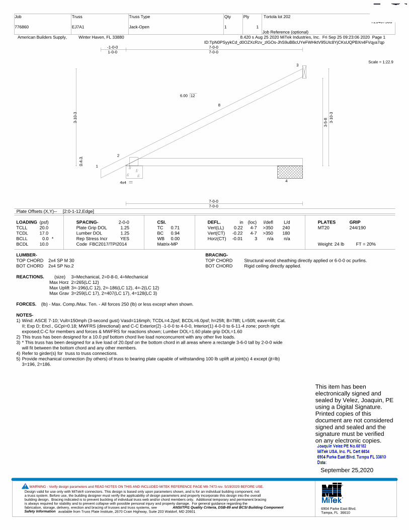
Design valid for use only with MiTek® connectors. This design is based only upon parameters shown, and is for an individual building component, not a truss system. Before use, the building designer must verify the applicability of design parameters and properly incorporate this design into the overall building design. Bracing indicated is to prevent buckling of individual truss web and/or chord members only. Additional temporary and permanent bracing is always required for stability and to prevent collapse with possible personal injury and property damage. For general guidance regarding the fabrication, storage, delivery, erection and bracing of trusses and truss systems, see ANSI/TPI1 Quality Criteria, DSB-89 and BCSI Building Component
available from Truss Plate Institute, 2670 Crain Highway, Suite 203 Waldorf, MD 20601Safety Information
WARNING - Verify design parameters and READ NOTES ON THIS AND INCLUDED MITEK REFERENCE PAGE MII-7473 rev. 5/19/2020 BEFORE USE.
6904 Parke East Blvd.Tampa, FL 36610
Job
776860
Truss
EJ7A1
Truss Type
Jack-Open
Qty
1
Ply
1
Tortola lot 202
Job Reference (optional)
T21407506
8.420 s Aug 25 2020 MiTek Industries, Inc. Fri Sep 25 09:23:06 2020 Page 1 American Builders Supply, Winter Haven, FL 33880ID:TpN0PSyykCd_d0OZXcRzv_zlGOs-JhS9uBBcUYeFWHktV95UIc8YjCKsUQPBXn4FVqya7qp
Scale = 1:22.9
1
2
8
3
44x4
7-0-07-0-0
-1-0-01-0-0
7-0-07-0-0
0-4-
3
3-10
-3
3-5-
8
3-10
-3
6.00 12
Plate Offsets (X,Y)-- [2:0-1-12,Edge]
LOADING (psf)TCLLTCDLBCLLBCDL
20.017.0
0.0 *10.0
SPACING-Plate Grip DOLLumber DOL Rep Stress IncrCode
2-0-01.251.25YES
FBC2017/TPI2014
CSI.TCBCWBMatrix-MP
0.710.940.00
DEFL.Vert(LL)Vert(CT)Horz(CT)
in0.22
-0.22-0.01
(loc)4-74-7
3
l/defl>350>350
n/a
L/d240180n/a
PLATESMT20
Weight: 24 lb FT = 20%
GRIP244/190
LUMBER-TOP CHORD 2x4 SP M 30BOT CHORD 2x4 SP No.2
BRACING-TOP CHORD Structural wood sheathing directly applied or 6-0-0 oc purlins.BOT CHORD Rigid ceiling directly applied.
REACTIONS. (size) 3=Mechanical, 2=0-8-0, 4=MechanicalMax Horz 2=265(LC 12)Max Uplift 3=-196(LC 12), 2=-186(LC 12), 4=-2(LC 12)Max Grav 3=259(LC 17), 2=407(LC 17), 4=128(LC 3)
FORCES. (lb) - Max. Comp./Max. Ten. - All forces 250 (lb) or less except when shown.
NOTES-1) Wind: ASCE 7-10; Vult=150mph (3-second gust) Vasd=116mph; TCDL=4.2psf; BCDL=6.0psf; h=25ft; B=78ft; L=50ft; eave=6ft; Cat.
II; Exp D; Encl., GCpi=0.18; MWFRS (directional) and C-C Exterior(2) -1-0-0 to 4-0-0, Interior(1) 4-0-0 to 6-11-4 zone; porch rightexposed;C-C for members and forces & MWFRS for reactions shown; Lumber DOL=1.60 plate grip DOL=1.60
2) This truss has been designed for a 10.0 psf bottom chord live load nonconcurrent with any other live loads.3) * This truss has been designed for a live load of 20.0psf on the bottom chord in all areas where a rectangle 3-6-0 tall by 2-0-0 wide
will fit between the bottom chord and any other members.4) Refer to girder(s) for truss to truss connections.5) Provide mechanical connection (by others) of truss to bearing plate capable of withstanding 100 lb uplift at joint(s) 4 except (jt=lb)
3=196, 2=186.
This item has beenelectronically signed andsealed by Velez, Joaquin, PEusing a Digital Signature.Printed copies of thisdocument are not consideredsigned and sealed and thesignature must be verified on any electronic copies.
September 25,2020
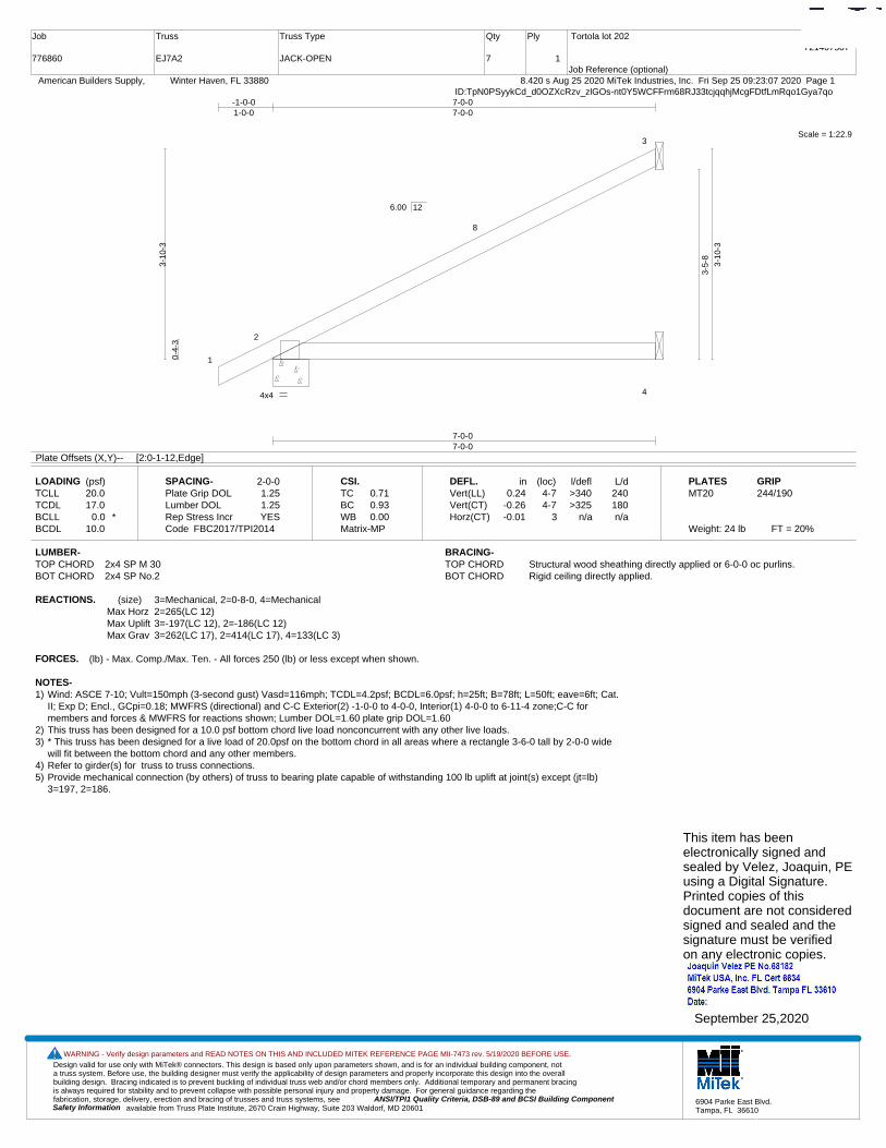
Design valid for use only with MiTek® connectors. This design is based only upon parameters shown, and is for an individual building component, not a truss system. Before use, the building designer must verify the applicability of design parameters and properly incorporate this design into the overall building design. Bracing indicated is to prevent buckling of individual truss web and/or chord members only. Additional temporary and permanent bracing is always required for stability and to prevent collapse with possible personal injury and property damage. For general guidance regarding the fabrication, storage, delivery, erection and bracing of trusses and truss systems, see ANSI/TPI1 Quality Criteria, DSB-89 and BCSI Building Component
available from Truss Plate Institute, 2670 Crain Highway, Suite 203 Waldorf, MD 20601Safety Information
WARNING - Verify design parameters and READ NOTES ON THIS AND INCLUDED MITEK REFERENCE PAGE MII-7473 rev. 5/19/2020 BEFORE USE.
6904 Parke East Blvd.Tampa, FL 36610
Job
776860
Truss
EJ7A2
Truss Type
JACK-OPEN
Qty
7
Ply
1
Tortola lot 202
Job Reference (optional)
T21407507
8.420 s Aug 25 2020 MiTek Industries, Inc. Fri Sep 25 09:23:07 2020 Page 1 American Builders Supply, Winter Haven, FL 33880ID:TpN0PSyykCd_d0OZXcRzv_zlGOs-nt0Y5WCFFrm68RJ33tcjqqhjMcgFDtfLmRqo1Gya7qo
Scale = 1:22.9
1
2
8
3
44x4
7-0-07-0-0
-1-0-01-0-0
7-0-07-0-0
0-4-
3
3-10
-3
3-5-
8
3-10
-3
6.00 12
Plate Offsets (X,Y)-- [2:0-1-12,Edge]
LOADING (psf)TCLLTCDLBCLLBCDL
20.017.0
0.0 *10.0
SPACING-Plate Grip DOLLumber DOL Rep Stress IncrCode
2-0-01.251.25YES
FBC2017/TPI2014
CSI.TCBCWBMatrix-MP
0.710.930.00
DEFL.Vert(LL)Vert(CT)Horz(CT)
in0.24
-0.26-0.01
(loc)4-74-7
3
l/defl>340>325
n/a
L/d240180n/a
PLATESMT20
Weight: 24 lb FT = 20%
GRIP244/190
LUMBER-TOP CHORD 2x4 SP M 30BOT CHORD 2x4 SP No.2
BRACING-TOP CHORD Structural wood sheathing directly applied or 6-0-0 oc purlins.BOT CHORD Rigid ceiling directly applied.
REACTIONS. (size) 3=Mechanical, 2=0-8-0, 4=MechanicalMax Horz 2=265(LC 12)Max Uplift 3=-197(LC 12), 2=-186(LC 12)Max Grav 3=262(LC 17), 2=414(LC 17), 4=133(LC 3)
FORCES. (lb) - Max. Comp./Max. Ten. - All forces 250 (lb) or less except when shown.
NOTES-1) Wind: ASCE 7-10; Vult=150mph (3-second gust) Vasd=116mph; TCDL=4.2psf; BCDL=6.0psf; h=25ft; B=78ft; L=50ft; eave=6ft; Cat.
II; Exp D; Encl., GCpi=0.18; MWFRS (directional) and C-C Exterior(2) -1-0-0 to 4-0-0, Interior(1) 4-0-0 to 6-11-4 zone;C-C formembers and forces & MWFRS for reactions shown; Lumber DOL=1.60 plate grip DOL=1.60
2) This truss has been designed for a 10.0 psf bottom chord live load nonconcurrent with any other live loads.3) * This truss has been designed for a live load of 20.0psf on the bottom chord in all areas where a rectangle 3-6-0 tall by 2-0-0 wide
will fit between the bottom chord and any other members.4) Refer to girder(s) for truss to truss connections.5) Provide mechanical connection (by others) of truss to bearing plate capable of withstanding 100 lb uplift at joint(s) except (jt=lb)
3=197, 2=186.
This item has beenelectronically signed andsealed by Velez, Joaquin, PEusing a Digital Signature.Printed copies of thisdocument are not consideredsigned and sealed and thesignature must be verified on any electronic copies.
September 25,2020

Design valid for use only with MiTek® connectors. This design is based only upon parameters shown, and is for an individual building component, not a truss system. Before use, the building designer must verify the applicability of design parameters and properly incorporate this design into the overall building design. Bracing indicated is to prevent buckling of individual truss web and/or chord members only. Additional temporary and permanent bracing is always required for stability and to prevent collapse with possible personal injury and property damage. For general guidance regarding the fabrication, storage, delivery, erection and bracing of trusses and truss systems, see ANSI/TPI1 Quality Criteria, DSB-89 and BCSI Building Component
available from Truss Plate Institute, 2670 Crain Highway, Suite 203 Waldorf, MD 20601Safety Information
WARNING - Verify design parameters and READ NOTES ON THIS AND INCLUDED MITEK REFERENCE PAGE MII-7473 rev. 5/19/2020 BEFORE USE.
6904 Parke East Blvd.Tampa, FL 36610
Job
776860
Truss
EJ7D
Truss Type
Jack-Open
Qty
6
Ply
1
Tortola lot 202
Job Reference (optional)
T21407508
8.420 s Aug 25 2020 MiTek Industries, Inc. Fri Sep 25 09:23:07 2020 Page 1 American Builders Supply, Winter Haven, FL 33880ID:TpN0PSyykCd_d0OZXcRzv_zlGOs-nt0Y5WCFFrm68RJ33tcjqqhkKchJDtfLmRqo1Gya7qo
Scale = 1:22.2
1
28
9
3
44x4
6-9-06-9-0
-1-0-01-0-0
6-9-06-9-0
0-4-
3
3-8-
11
3-4-
0
3-8-
11
6.00 12
Plate Offsets (X,Y)-- [2:0-1-8,Edge]
LOADING (psf)TCLLTCDLBCLLBCDL
20.017.0
0.0 *10.0
SPACING-Plate Grip DOLLumber DOL Rep Stress IncrCode
2-0-01.251.25YES
FBC2017/TPI2014
CSI.TCBCWBMatrix-MP
0.650.860.00
DEFL.Vert(LL)Vert(CT)Horz(CT)
in0.21
-0.22-0.01
(loc)4-74-7
3
l/defl>377>360
n/a
L/d240180n/a
PLATESMT20
Weight: 23 lb FT = 20%
GRIP244/190
LUMBER-TOP CHORD 2x4 SP M 30BOT CHORD 2x4 SP No.2
BRACING-TOP CHORD Structural wood sheathing directly applied or 6-0-0 oc purlins.BOT CHORD Rigid ceiling directly applied or 5-7-8 oc bracing.
REACTIONS. (size) 3=Mechanical, 2=0-8-0, 4=MechanicalMax Horz 2=257(LC 12)Max Uplift 3=-189(LC 12), 2=-183(LC 12)Max Grav 3=253(LC 17), 2=402(LC 17), 4=128(LC 3)
FORCES. (lb) - Max. Comp./Max. Ten. - All forces 250 (lb) or less except when shown.
NOTES-1) Wind: ASCE 7-10; Vult=150mph (3-second gust) Vasd=116mph; TCDL=4.2psf; BCDL=6.0psf; h=25ft; B=78ft; L=50ft; eave=6ft; Cat.
II; Exp D; Encl., GCpi=0.18; MWFRS (directional) and C-C Exterior(2) -1-0-0 to 4-0-0, Interior(1) 4-0-0 to 6-8-4 zone; porch rightexposed;C-C for members and forces & MWFRS for reactions shown; Lumber DOL=1.60 plate grip DOL=1.60
2) This truss has been designed for a 10.0 psf bottom chord live load nonconcurrent with any other live loads.3) * This truss has been designed for a live load of 20.0psf on the bottom chord in all areas where a rectangle 3-6-0 tall by 2-0-0 wide
will fit between the bottom chord and any other members.4) Refer to girder(s) for truss to truss connections.5) Provide mechanical connection (by others) of truss to bearing plate capable of withstanding 100 lb uplift at joint(s) except (jt=lb)
3=189, 2=183.
This item has beenelectronically signed andsealed by Velez, Joaquin, PEusing a Digital Signature.Printed copies of thisdocument are not consideredsigned and sealed and thesignature must be verified on any electronic copies.
September 25,2020
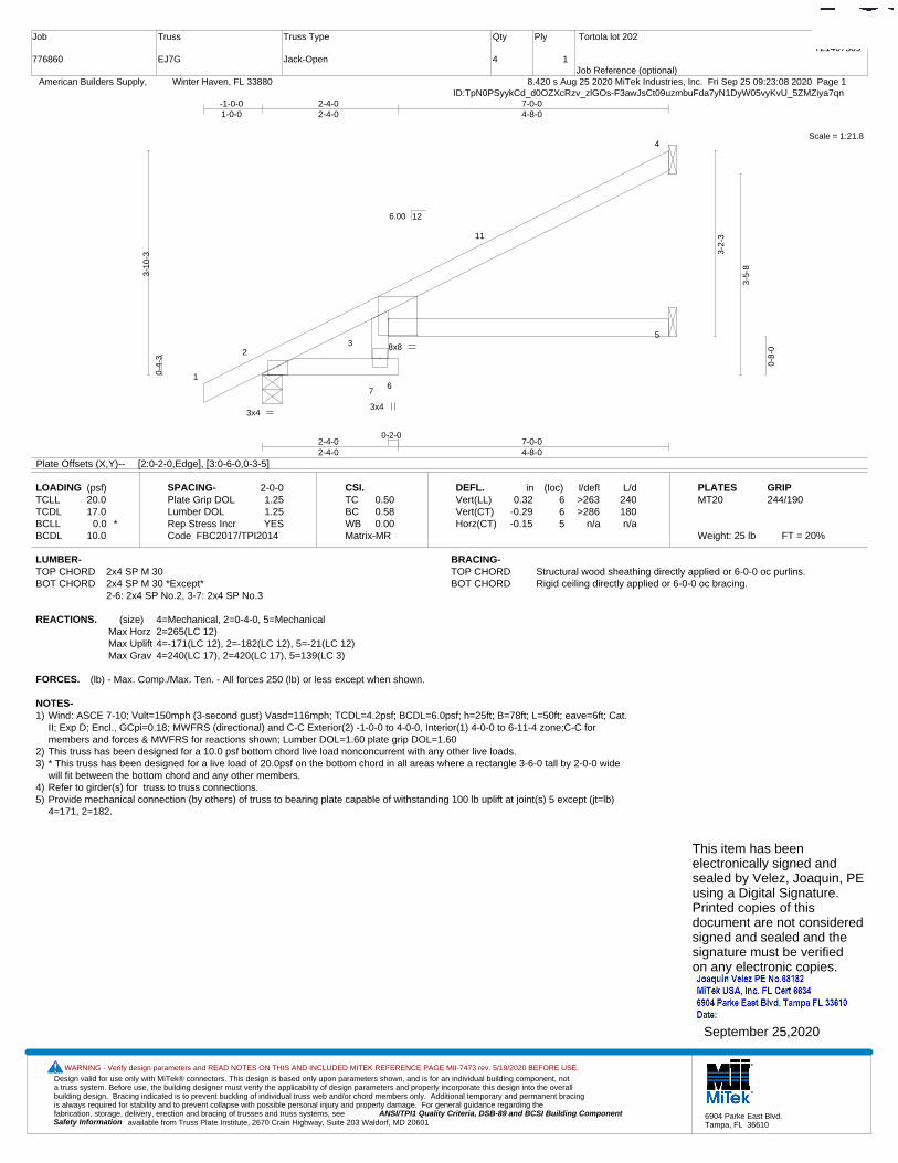
Design valid for use only with MiTek® connectors. This design is based only upon parameters shown, and is for an individual building component, not a truss system. Before use, the building designer must verify the applicability of design parameters and properly incorporate this design into the overall building design. Bracing indicated is to prevent buckling of individual truss web and/or chord members only. Additional temporary and permanent bracing is always required for stability and to prevent collapse with possible personal injury and property damage. For general guidance regarding the fabrication, storage, delivery, erection and bracing of trusses and truss systems, see ANSI/TPI1 Quality Criteria, DSB-89 and BCSI Building Component
available from Truss Plate Institute, 2670 Crain Highway, Suite 203 Waldorf, MD 20601Safety Information
WARNING - Verify design parameters and READ NOTES ON THIS AND INCLUDED MITEK REFERENCE PAGE MII-7473 rev. 5/19/2020 BEFORE USE.
6904 Parke East Blvd.Tampa, FL 36610
Job
776860
Truss
EJ7G
Truss Type
Jack-Open
Qty
4
Ply
1
Tortola lot 202
Job Reference (optional)
T21407509
8.420 s Aug 25 2020 MiTek Industries, Inc. Fri Sep 25 09:23:08 2020 Page 1 American Builders Supply, Winter Haven, FL 33880ID:TpN0PSyykCd_d0OZXcRzv_zlGOs-F3awJsCt09uzmbuFda7yN1DyW05vyKvU_5ZMZiya7qn
Scale = 1:21.8
1
23
76
11
4
5
3x4 3x4
8x8
0-2-02-4-02-4-0
7-0-04-8-0
-1-0-01-0-0
2-4-02-4-0
7-0-04-8-0
0-4-
3
3-10
-3
3-2-
3
3-5-
8
0-8-
0
6.00 12
Plate Offsets (X,Y)-- [2:0-2-0,Edge], [3:0-6-0,0-3-5]
LOADING (psf)TCLLTCDLBCLLBCDL
20.017.0
0.0 *10.0
SPACING-Plate Grip DOLLumber DOL Rep Stress IncrCode
2-0-01.251.25YES
FBC2017/TPI2014
CSI.TCBCWBMatrix-MR
0.500.580.00
DEFL.Vert(LL)Vert(CT)Horz(CT)
in0.32
-0.29-0.15
(loc)665
l/defl>263>286
n/a
L/d240180n/a
PLATESMT20
Weight: 25 lb FT = 20%
GRIP244/190
LUMBER-TOP CHORD 2x4 SP M 30BOT CHORD 2x4 SP M 30 *Except*
2-6: 2x4 SP No.2, 3-7: 2x4 SP No.3
BRACING-TOP CHORD Structural wood sheathing directly applied or 6-0-0 oc purlins.BOT CHORD Rigid ceiling directly applied or 6-0-0 oc bracing.
REACTIONS. (size) 4=Mechanical, 2=0-4-0, 5=MechanicalMax Horz 2=265(LC 12)Max Uplift 4=-171(LC 12), 2=-182(LC 12), 5=-21(LC 12)Max Grav 4=240(LC 17), 2=420(LC 17), 5=139(LC 3)
FORCES. (lb) - Max. Comp./Max. Ten. - All forces 250 (lb) or less except when shown.
NOTES-1) Wind: ASCE 7-10; Vult=150mph (3-second gust) Vasd=116mph; TCDL=4.2psf; BCDL=6.0psf; h=25ft; B=78ft; L=50ft; eave=6ft; Cat.
II; Exp D; Encl., GCpi=0.18; MWFRS (directional) and C-C Exterior(2) -1-0-0 to 4-0-0, Interior(1) 4-0-0 to 6-11-4 zone;C-C formembers and forces & MWFRS for reactions shown; Lumber DOL=1.60 plate grip DOL=1.60
2) This truss has been designed for a 10.0 psf bottom chord live load nonconcurrent with any other live loads.3) * This truss has been designed for a live load of 20.0psf on the bottom chord in all areas where a rectangle 3-6-0 tall by 2-0-0 wide
will fit between the bottom chord and any other members.4) Refer to girder(s) for truss to truss connections.5) Provide mechanical connection (by others) of truss to bearing plate capable of withstanding 100 lb uplift at joint(s) 5 except (jt=lb)
4=171, 2=182.
This item has beenelectronically signed andsealed by Velez, Joaquin, PEusing a Digital Signature.Printed copies of thisdocument are not consideredsigned and sealed and thesignature must be verified on any electronic copies.
September 25,2020
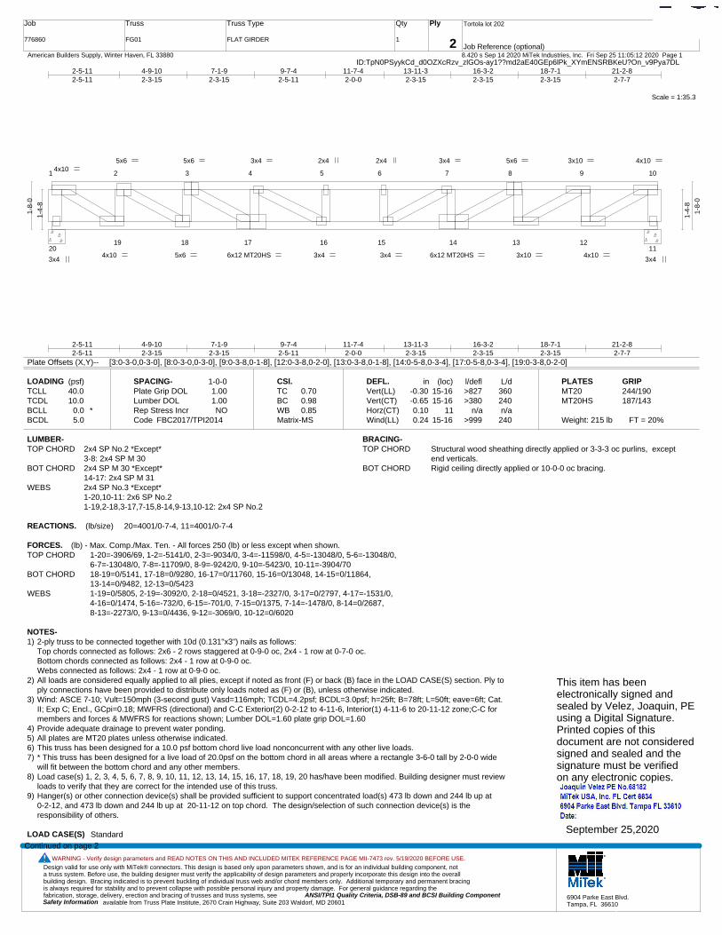
Design valid for use only with MiTek® connectors. This design is based only upon parameters shown, and is for an individual building component, not a truss system. Before use, the building designer must verify the applicability of design parameters and properly incorporate this design into the overall building design. Bracing indicated is to prevent buckling of individual truss web and/or chord members only. Additional temporary and permanent bracing is always required for stability and to prevent collapse with possible personal injury and property damage. For general guidance regarding the fabrication, storage, delivery, erection and bracing of trusses and truss systems, see ANSI/TPI1 Quality Criteria, DSB-89 and BCSI Building Component
available from Truss Plate Institute, 2670 Crain Highway, Suite 203 Waldorf, MD 20601Safety Information
WARNING - Verify design parameters and READ NOTES ON THIS AND INCLUDED MITEK REFERENCE PAGE MII-7473 rev. 5/19/2020 BEFORE USE.
6904 Parke East Blvd.Tampa, FL 36610
Job
776860
Truss
FG01
Truss Type
FLAT GIRDER
Qty
1
Ply
2
Tortola lot 202
Job Reference (optional)
T21407510
8.420 s Sep 14 2020 MiTek Industries, Inc. Fri Sep 25 11:05:12 2020 Page 1 American Builders Supply, Winter Haven, FL 33880ID:TpN0PSyykCd_d0OZXcRzv_zlGOs-ay1??md2aE40GEp6lPk_XYmENSRBKeU?On_v9Pya7DL
Scale = 1:35.3
1 2 3 4 5 6 7 8 9 10
2019 18 17 16 15 14 13 12
11
3x4
4x10 5x6 4x10
3x4 6x12 MT20HS4x10
5x6
5x6
3x4
3x4
2x4 2x4
3x4
3x4
6x12 MT20HS
5x6
3x10
3x10
4x10
2-5-112-5-11
4-9-102-3-15
7-1-92-3-15
9-7-42-5-11
11-7-42-0-0
13-11-32-3-15
16-3-22-3-15
18-7-12-3-15
21-2-82-7-7
2-5-112-5-11
4-9-102-3-15
7-1-92-3-15
9-7-42-5-11
11-7-42-0-0
13-11-32-3-15
16-3-22-3-15
18-7-12-3-15
21-2-82-7-7
1-4-
8
1-8-
0
1-4-
8
1-8-
0
Plate Offsets (X,Y)-- [3:0-3-0,0-3-0], [8:0-3-0,0-3-0], [9:0-3-8,0-1-8], [12:0-3-8,0-2-0], [13:0-3-8,0-1-8], [14:0-5-8,0-3-4], [17:0-5-8,0-3-4], [19:0-3-8,0-2-0]
LOADING (psf)TCLLTCDLBCLLBCDL
40.010.0
0.0 *5.0
SPACING-Plate Grip DOLLumber DOL Rep Stress IncrCode
1-0-01.001.00NO
FBC2017/TPI2014
CSI.TCBCWBMatrix-MS
0.700.980.85
DEFL.Vert(LL)Vert(CT)Horz(CT)Wind(LL)
in-0.30-0.650.100.24
(loc)15-1615-16
1115-16
l/defl>827>380
n/a>999
L/d360240n/a
240
PLATESMT20MT20HS
Weight: 215 lb FT = 20%
GRIP244/190187/143
LUMBER-TOP CHORD 2x4 SP No.2 *Except*
3-8: 2x4 SP M 30BOT CHORD 2x4 SP M 30 *Except*
14-17: 2x4 SP M 31WEBS 2x4 SP No.3 *Except*
1-20,10-11: 2x6 SP No.21-19,2-18,3-17,7-15,8-14,9-13,10-12: 2x4 SP No.2
BRACING-TOP CHORD Structural wood sheathing directly applied or 3-3-3 oc purlins, except
end verticals.BOT CHORD Rigid ceiling directly applied or 10-0-0 oc bracing.
REACTIONS. (lb/size) 20=4001/0-7-4, 11=4001/0-7-4
FORCES. (lb) - Max. Comp./Max. Ten. - All forces 250 (lb) or less except when shown.TOP CHORD 1-20=-3906/69, 1-2=-5141/0, 2-3=-9034/0, 3-4=-11598/0, 4-5=-13048/0, 5-6=-13048/0,
6-7=-13048/0, 7-8=-11709/0, 8-9=-9242/0, 9-10=-5423/0, 10-11=-3904/70BOT CHORD 18-19=0/5141, 17-18=0/9280, 16-17=0/11760, 15-16=0/13048, 14-15=0/11864,
13-14=0/9482, 12-13=0/5423WEBS 1-19=0/5805, 2-19=-3092/0, 2-18=0/4521, 3-18=-2327/0, 3-17=0/2797, 4-17=-1531/0,
4-16=0/1474, 5-16=-732/0, 6-15=-701/0, 7-15=0/1375, 7-14=-1478/0, 8-14=0/2687, 8-13=-2273/0, 9-13=0/4436, 9-12=-3069/0, 10-12=0/6020
NOTES-1) 2-ply truss to be connected together with 10d (0.131"x3") nails as follows:
Top chords connected as follows: 2x6 - 2 rows staggered at 0-9-0 oc, 2x4 - 1 row at 0-7-0 oc.Bottom chords connected as follows: 2x4 - 1 row at 0-9-0 oc.Webs connected as follows: 2x4 - 1 row at 0-9-0 oc.
2) All loads are considered equally applied to all plies, except if noted as front (F) or back (B) face in the LOAD CASE(S) section. Ply toply connections have been provided to distribute only loads noted as (F) or (B), unless otherwise indicated.
3) Wind: ASCE 7-10; Vult=150mph (3-second gust) Vasd=116mph; TCDL=4.2psf; BCDL=3.0psf; h=25ft; B=78ft; L=50ft; eave=6ft; Cat.II; Exp C; Encl., GCpi=0.18; MWFRS (directional) and C-C Exterior(2) 0-2-12 to 4-11-6, Interior(1) 4-11-6 to 20-11-12 zone;C-C formembers and forces & MWFRS for reactions shown; Lumber DOL=1.60 plate grip DOL=1.60
4) Provide adequate drainage to prevent water ponding.5) All plates are MT20 plates unless otherwise indicated. 6) This truss has been designed for a 10.0 psf bottom chord live load nonconcurrent with any other live loads.7) * This truss has been designed for a live load of 20.0psf on the bottom chord in all areas where a rectangle 3-6-0 tall by 2-0-0 wide
will fit between the bottom chord and any other members.8) Load case(s) 1, 2, 3, 4, 5, 6, 7, 8, 9, 10, 11, 12, 13, 14, 15, 16, 17, 18, 19, 20 has/have been modified. Building designer must review
loads to verify that they are correct for the intended use of this truss.9) Hanger(s) or other connection device(s) shall be provided sufficient to support concentrated load(s) 473 lb down and 244 lb up at
0-2-12, and 473 lb down and 244 lb up at 20-11-12 on top chord. The design/selection of such connection device(s) is theresponsibility of others.
LOAD CASE(S) Standard
Continued on page 2
This item has beenelectronically signed andsealed by Velez, Joaquin, PEusing a Digital Signature.Printed copies of thisdocument are not consideredsigned and sealed and thesignature must be verified on any electronic copies.
September 25,2020

Design valid for use only with MiTek® connectors. This design is based only upon parameters shown, and is for an individual building component, not a truss system. Before use, the building designer must verify the applicability of design parameters and properly incorporate this design into the overall building design. Bracing indicated is to prevent buckling of individual truss web and/or chord members only. Additional temporary and permanent bracing is always required for stability and to prevent collapse with possible personal injury and property damage. For general guidance regarding the fabrication, storage, delivery, erection and bracing of trusses and truss systems, see ANSI/TPI1 Quality Criteria, DSB-89 and BCSI Building Component
available from Truss Plate Institute, 2670 Crain Highway, Suite 203 Waldorf, MD 20601Safety Information
WARNING - Verify design parameters and READ NOTES ON THIS AND INCLUDED MITEK REFERENCE PAGE MII-7473 rev. 5/19/2020 BEFORE USE.
6904 Parke East Blvd.Tampa, FL 36610
Job
776860
Truss
FG01
Truss Type
FLAT GIRDER
Qty
1
Ply
2
Tortola lot 202
Job Reference (optional)
T21407510
8.420 s Sep 14 2020 MiTek Industries, Inc. Fri Sep 25 11:05:12 2020 Page 2 American Builders Supply, Winter Haven, FL 33880ID:TpN0PSyykCd_d0OZXcRzv_zlGOs-ay1??md2aE40GEp6lPk_XYmENSRBKeU?On_v9Pya7DL
LOAD CASE(S) Standard1) Dead + Roof Live (balanced): Lumber Increase=1.00, Plate Increase=1.00
Uniform Loads (plf)Vert: 1-10=-335, 11-20=-5
Concentrated Loads (lb)Vert: 1=-473 10=-473
2) Dead + 0.75 Roof Live (balanced): Lumber Increase=1.00, Plate Increase=1.00Uniform Loads (plf)
Vert: 1-10=-296, 11-20=-5Concentrated Loads (lb)
Vert: 1=-387 10=-3873) Dead + Uninhabitable Attic Without Storage: Lumber Increase=1.25, Plate Increase=1.25
Uniform Loads (plf)Vert: 1-10=-208, 11-20=-15
Concentrated Loads (lb)Vert: 1=-215 10=-215
4) Dead + 0.6 C-C Wind (Pos. Internal) Case 1: Lumber Increase=1.60, Plate Increase=1.60Uniform Loads (plf)
Vert: 1-3=-11, 3-10=-17, 11-20=-3Concentrated Loads (lb)
Vert: 1=244 10=2445) Dead + 0.6 C-C Wind (Pos. Internal) Case 2: Lumber Increase=1.60, Plate Increase=1.60
Uniform Loads (plf)Vert: 1-8=-17, 8-10=-11, 11-20=-3
Concentrated Loads (lb)Vert: 1=244 10=244
6) Dead + 0.6 C-C Wind (Neg. Internal) Case 1: Lumber Increase=1.60, Plate Increase=1.60Uniform Loads (plf)
Vert: 1-10=-220, 11-20=-5Concentrated Loads (lb)
Vert: 1=-220 10=-2207) Dead + 0.6 C-C Wind (Neg. Internal) Case 2: Lumber Increase=1.60, Plate Increase=1.60
Uniform Loads (plf)Vert: 1-10=-220, 11-20=-5
Concentrated Loads (lb)Vert: 1=-220 10=-220
8) Dead + 0.6 MWFRS Wind (Pos. Internal) Left: Lumber Increase=1.60, Plate Increase=1.60Uniform Loads (plf)
Vert: 1-10=-48, 11-20=-3Concentrated Loads (lb)
Vert: 1=164 10=1649) Dead + 0.6 MWFRS Wind (Pos. Internal) Right: Lumber Increase=1.60, Plate Increase=1.60
Uniform Loads (plf)Vert: 1-10=-48, 11-20=-3
Concentrated Loads (lb)Vert: 1=164 10=164
10) Dead + 0.6 MWFRS Wind (Neg. Internal) Left: Lumber Increase=1.60, Plate Increase=1.60Uniform Loads (plf)
Vert: 1-10=-194, 11-20=-5Concentrated Loads (lb)
Vert: 1=-172 10=-17211) Dead + 0.6 MWFRS Wind (Neg. Internal) Right: Lumber Increase=1.60, Plate Increase=1.60
Uniform Loads (plf)Vert: 1-10=-194, 11-20=-5
Concentrated Loads (lb)Vert: 1=-172 10=-172
12) Dead + 0.6 MWFRS Wind (Pos. Internal) 1st Parallel: Lumber Increase=1.60, Plate Increase=1.60Uniform Loads (plf)
Vert: 1-10=-48, 11-20=-3Concentrated Loads (lb)
Vert: 1=164 10=16413) Dead + 0.6 MWFRS Wind (Pos. Internal) 2nd Parallel: Lumber Increase=1.60, Plate Increase=1.60
Uniform Loads (plf)Vert: 1-10=-103, 11-20=-3
Concentrated Loads (lb)Vert: 1=42 10=42
14) Dead + 0.6 MWFRS Wind (Neg. Internal) 1st Parallel: Lumber Increase=1.60, Plate Increase=1.60Uniform Loads (plf)
Vert: 1-10=-194, 11-20=-5Concentrated Loads (lb)
Vert: 1=-172 10=-17215) Dead + 0.6 MWFRS Wind (Neg. Internal) 2nd Parallel: Lumber Increase=1.60, Plate Increase=1.60
Uniform Loads (plf)Vert: 1-10=-194, 11-20=-5
Concentrated Loads (lb)Vert: 1=-172 10=-172
16) Dead: Lumber Increase=0.90, Plate Increase=0.90 Plt. metal=0.90
Continued on page 3

Design valid for use only with MiTek® connectors. This design is based only upon parameters shown, and is for an individual building component, not a truss system. Before use, the building designer must verify the applicability of design parameters and properly incorporate this design into the overall building design. Bracing indicated is to prevent buckling of individual truss web and/or chord members only. Additional temporary and permanent bracing is always required for stability and to prevent collapse with possible personal injury and property damage. For general guidance regarding the fabrication, storage, delivery, erection and bracing of trusses and truss systems, see ANSI/TPI1 Quality Criteria, DSB-89 and BCSI Building Component
available from Truss Plate Institute, 2670 Crain Highway, Suite 203 Waldorf, MD 20601Safety Information
WARNING - Verify design parameters and READ NOTES ON THIS AND INCLUDED MITEK REFERENCE PAGE MII-7473 rev. 5/19/2020 BEFORE USE.
6904 Parke East Blvd.Tampa, FL 36610
Job
776860
Truss
FG01
Truss Type
FLAT GIRDER
Qty
1
Ply
2
Tortola lot 202
Job Reference (optional)
T21407510
8.420 s Sep 14 2020 MiTek Industries, Inc. Fri Sep 25 11:05:12 2020 Page 3 American Builders Supply, Winter Haven, FL 33880ID:TpN0PSyykCd_d0OZXcRzv_zlGOs-ay1??md2aE40GEp6lPk_XYmENSRBKeU?On_v9Pya7DL
LOAD CASE(S) StandardUniform Loads (plf)
Vert: 1-10=-179, 11-20=-5Concentrated Loads (lb)
Vert: 1=-129 10=-12917) Dead + 0.75 Roof Live (bal.) + 0.75(0.6 MWFRS Wind (Neg. Int) Left): Lumber Increase=1.60, Plate Increase=1.60
Uniform Loads (plf)Vert: 1-10=-307, 11-20=-5
Concentrated Loads (lb)Vert: 1=-419 10=-419
18) Dead + 0.75 Roof Live (bal.) + 0.75(0.6 MWFRS Wind (Neg. Int) Right): Lumber Increase=1.60, Plate Increase=1.60Uniform Loads (plf)
Vert: 1-10=-307, 11-20=-5Concentrated Loads (lb)
Vert: 1=-419 10=-41919) Dead + 0.75 Roof Live (bal.) + 0.75(0.6 MWFRS Wind (Neg. Int) 1st Parallel): Lumber Increase=1.60, Plate Increase=1.60
Uniform Loads (plf)Vert: 1-10=-307, 11-20=-5
Concentrated Loads (lb)Vert: 1=-419 10=-419
20) Dead + 0.75 Roof Live (bal.) + 0.75(0.6 MWFRS Wind (Neg. Int) 2nd Parallel): Lumber Increase=1.60, Plate Increase=1.60Uniform Loads (plf)
Vert: 1-10=-307, 11-20=-5Concentrated Loads (lb)
Vert: 1=-419 10=-419
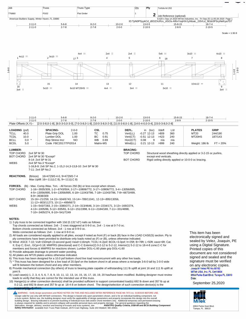
Design valid for use only with MiTek® connectors. This design is based only upon parameters shown, and is for an individual building component, not a truss system. Before use, the building designer must verify the applicability of design parameters and properly incorporate this design into the overall building design. Bracing indicated is to prevent buckling of individual truss web and/or chord members only. Additional temporary and permanent bracing is always required for stability and to prevent collapse with possible personal injury and property damage. For general guidance regarding the fabrication, storage, delivery, erection and bracing of trusses and truss systems, see ANSI/TPI1 Quality Criteria, DSB-89 and BCSI Building Component
available from Truss Plate Institute, 2670 Crain Highway, Suite 203 Waldorf, MD 20601Safety Information
WARNING - Verify design parameters and READ NOTES ON THIS AND INCLUDED MITEK REFERENCE PAGE MII-7473 rev. 5/19/2020 BEFORE USE.
6904 Parke East Blvd.Tampa, FL 36610
Job
776860
Truss
FG02
Truss Type
Flat Girder
Qty
1
Ply
2
Tortola lot 202
Job Reference (optional)
T21407511
8.420 s Sep 14 2020 MiTek Industries, Inc. Fri Sep 25 11:05:26 2020 Page 1 American Builders Supply, Winter Haven, FL 33880ID:TpN0PSyykCd_d0OZXcRzv_zlGOs-AftIxYoqHXr1yNtoaL_G5VLd_5Edc0P3cyNefcya7D7
Scale = 1:30.9
1 2 3 4 5 6 7 8
1615 14 13 12 11 10
9
17 18
3x4
4x12 5x6 4x10
3x4 6x10 MT20HS5x10
3x10 4x4
4x4
2x4 2x4
3x4 3x10
3x10
4x12
2-11-02-11-0
5-6-82-7-8
8-2-02-7-8
10-2-02-0-0
13-0-52-10-5
15-8-152-8-9
18-7-42-10-5
2-11-02-11-0
5-6-82-7-8
8-2-02-7-8
10-2-02-0-0
13-0-52-10-5
15-8-152-8-9
18-7-42-10-5
1-8-
0
1-4-
8
1-8-
0
Plate Offsets (X,Y)-- [2:0-3-8,0-1-8], [6:0-3-0,0-3-0], [7:0-3-8,0-1-8], [10:0-3-8,0-2-0], [11:0-3-8,0-1-8], [14:0-4-0,0-3-4], [15:0-3-8,0-2-8]
LOADING (psf)TCLLTCDLBCLLBCDL
40.010.0
0.0 *5.0
SPACING-Plate Grip DOLLumber DOL Rep Stress IncrCode
2-0-01.001.00NO
FBC2017/TPI2014
CSI.TCBCWBMatrix-MS
0.750.910.69
DEFL.Vert(LL)Vert(CT)Horz(CT)Wind(LL)
in-0.27-0.510.080.21
(loc)12-1312-13
912-13
l/defl>809>423
n/a>999
L/d360240n/a
240
PLATESMT20MT20HS
Weight: 186 lb FT = 20%
GRIP244/190187/143
LUMBER-TOP CHORD 2x4 SP M 30BOT CHORD 2x4 SP M 30 *Except*
9-14: 2x4 SP M 31WEBS 2x4 SP No.3 *Except*
1-16,8-9: 2x6 SP No.2, 1-15,2-14,3-13,8-10: 2x4 SP M 307-11: 2x4 SP No.2
BRACING-TOP CHORD Structural wood sheathing directly applied or 3-2-15 oc purlins,
except end verticals.BOT CHORD Rigid ceiling directly applied or 10-0-0 oc bracing.
REACTIONS. (lb/size) 16=4729/0-4-0, 9=4729/0-7-4Max Uplift 16=-111(LC 8), 9=-111(LC 8)
FORCES. (lb) - Max. Comp./Max. Ten. - All forces 250 (lb) or less except when shown.TOP CHORD 1-16=-3935/309, 1-2=-6743/504, 2-17=-10806/772, 3-17=-10806/772, 3-4=-13056/895,
4-5=-13056/895, 5-6=-13056/895, 6-18=-11043/786, 7-18=-11043/786, 7-8=-6673/499, 8-9=-3938/309
BOT CHORD 15-16=-21/259, 14-15=-504/6743, 13-14=-789/11041, 12-13=-895/13056, 11-12=-803/11273, 10-11=-499/6673
WEBS 1-15=-543/7283, 2-15=-3380/271, 2-14=-313/4646, 3-14=-2234/171, 3-13=-169/2274, 4-13=-1005/86, 5-12=-935/81, 6-12=-151/1998, 6-11=-2184/169, 7-11=-331/4898, 7-10=-3405/274, 8-10=-541/7249
NOTES-1) 2-ply truss to be connected together with 10d (0.131"x3") nails as follows:
Top chords connected as follows: 2x6 - 2 rows staggered at 0-9-0 oc, 2x4 - 1 row at 0-7-0 oc.Bottom chords connected as follows: 2x4 - 1 row at 0-9-0 oc.Webs connected as follows: 2x4 - 1 row at 0-9-0 oc.
2) All loads are considered equally applied to all plies, except if noted as front (F) or back (B) face in the LOAD CASE(S) section. Ply toply connections have been provided to distribute only loads noted as (F) or (B), unless otherwise indicated.
3) Wind: ASCE 7-10; Vult=150mph (3-second gust) Vasd=116mph; TCDL=4.2psf; BCDL=3.0psf; h=25ft; B=78ft; L=50ft; eave=6ft; Cat.II; Exp C; Encl., GCpi=0.18; MWFRS (directional) and C-C Exterior(2) 0-2-12 to 5-2-12, Interior(1) 5-2-12 to 18-4-8 zone;C-C formembers and forces & MWFRS for reactions shown; Lumber DOL=1.60 plate grip DOL=1.60
4) Provide adequate drainage to prevent water ponding.5) All plates are MT20 plates unless otherwise indicated. 6) This truss has been designed for a 10.0 psf bottom chord live load nonconcurrent with any other live loads.7) * This truss has been designed for a live load of 20.0psf on the bottom chord in all areas where a rectangle 3-6-0 tall by 2-0-0 wide
will fit between the bottom chord and any other members.8) Provide mechanical connection (by others) of truss to bearing plate capable of withstanding 111 lb uplift at joint 16 and 111 lb uplift at
joint 9.9) Load case(s) 1, 2, 3, 4, 5, 6, 7, 8, 9, 10, 11, 12, 13, 14, 15, 16, 17, 18, 19, 20 has/have been modified. Building designer must review
loads to verify that they are correct for the intended use of this truss.10) Hanger(s) or other connection device(s) shall be provided sufficient to support concentrated load(s) 692 lb down and 357 lb up at
0-2-12, and 692 lb down and 357 lb up at 18-4-8 on bottom chord. The design/selection of such connection device(s) is theresponsibility of others.Continued on page 2
This item has beenelectronically signed andsealed by Velez, Joaquin, PEusing a Digital Signature.Printed copies of thisdocument are not consideredsigned and sealed and thesignature must be verified on any electronic copies.
September 25,2020
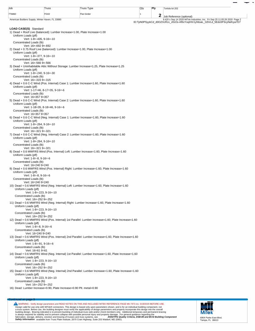
Design valid for use only with MiTek® connectors. This design is based only upon parameters shown, and is for an individual building component, not a truss system. Before use, the building designer must verify the applicability of design parameters and properly incorporate this design into the overall building design. Bracing indicated is to prevent buckling of individual truss web and/or chord members only. Additional temporary and permanent bracing is always required for stability and to prevent collapse with possible personal injury and property damage. For general guidance regarding the fabrication, storage, delivery, erection and bracing of trusses and truss systems, see ANSI/TPI1 Quality Criteria, DSB-89 and BCSI Building Component
available from Truss Plate Institute, 2670 Crain Highway, Suite 203 Waldorf, MD 20601Safety Information
WARNING - Verify design parameters and READ NOTES ON THIS AND INCLUDED MITEK REFERENCE PAGE MII-7473 rev. 5/19/2020 BEFORE USE.
6904 Parke East Blvd.Tampa, FL 36610
Job
776860
Truss
FG02
Truss Type
Flat Girder
Qty
1
Ply
2
Tortola lot 202
Job Reference (optional)
T21407511
8.420 s Sep 14 2020 MiTek Industries, Inc. Fri Sep 25 11:05:26 2020 Page 2 American Builders Supply, Winter Haven, FL 33880ID:TpN0PSyykCd_d0OZXcRzv_zlGOs-AftIxYoqHXr1yNtoaL_G5VLd_5Edc0P3cyNefcya7D7
LOAD CASE(S) Standard1) Dead + Roof Live (balanced): Lumber Increase=1.00, Plate Increase=1.00
Uniform Loads (plf)Vert: 1-8=-435, 9-16=-10
Concentrated Loads (lb)Vert: 16=-692 9=-692
2) Dead + 0.75 Roof Live (balanced): Lumber Increase=1.00, Plate Increase=1.00Uniform Loads (plf)
Vert: 1-8=-377, 9-16=-10Concentrated Loads (lb)
Vert: 16=-566 9=-5663) Dead + Uninhabitable Attic Without Storage: Lumber Increase=1.25, Plate Increase=1.25
Uniform Loads (plf)Vert: 1-8=-240, 9-16=-30
Concentrated Loads (lb)Vert: 16=-315 9=-315
4) Dead + 0.6 C-C Wind (Pos. Internal) Case 1: Lumber Increase=1.60, Plate Increase=1.60Uniform Loads (plf)
Vert: 1-17=46, 8-17=35, 9-16=-6Concentrated Loads (lb)
Vert: 16=357 9=3575) Dead + 0.6 C-C Wind (Pos. Internal) Case 2: Lumber Increase=1.60, Plate Increase=1.60
Uniform Loads (plf)Vert: 1-18=35, 8-18=46, 9-16=-6
Concentrated Loads (lb)Vert: 16=357 9=357
6) Dead + 0.6 C-C Wind (Neg. Internal) Case 1: Lumber Increase=1.60, Plate Increase=1.60Uniform Loads (plf)
Vert: 1-8=-264, 9-16=-10Concentrated Loads (lb)
Vert: 16=-321 9=-3217) Dead + 0.6 C-C Wind (Neg. Internal) Case 2: Lumber Increase=1.60, Plate Increase=1.60
Uniform Loads (plf)Vert: 1-8=-264, 9-16=-10
Concentrated Loads (lb)Vert: 16=-321 9=-321
8) Dead + 0.6 MWFRS Wind (Pos. Internal) Left: Lumber Increase=1.60, Plate Increase=1.60Uniform Loads (plf)
Vert: 1-8=-8, 9-16=-6Concentrated Loads (lb)
Vert: 16=240 9=2409) Dead + 0.6 MWFRS Wind (Pos. Internal) Right: Lumber Increase=1.60, Plate Increase=1.60
Uniform Loads (plf)Vert: 1-8=-8, 9-16=-6
Concentrated Loads (lb)Vert: 16=240 9=240
10) Dead + 0.6 MWFRS Wind (Neg. Internal) Left: Lumber Increase=1.60, Plate Increase=1.60Uniform Loads (plf)
Vert: 1-8=-223, 9-16=-10Concentrated Loads (lb)
Vert: 16=-252 9=-25211) Dead + 0.6 MWFRS Wind (Neg. Internal) Right: Lumber Increase=1.60, Plate Increase=1.60
Uniform Loads (plf)Vert: 1-8=-223, 9-16=-10
Concentrated Loads (lb)Vert: 16=-252 9=-252
12) Dead + 0.6 MWFRS Wind (Pos. Internal) 1st Parallel: Lumber Increase=1.60, Plate Increase=1.60Uniform Loads (plf)
Vert: 1-8=-8, 9-16=-6Concentrated Loads (lb)
Vert: 16=240 9=24013) Dead + 0.6 MWFRS Wind (Pos. Internal) 2nd Parallel: Lumber Increase=1.60, Plate Increase=1.60
Uniform Loads (plf)Vert: 1-8=-91, 9-16=-6
Concentrated Loads (lb)Vert: 16=61 9=61
14) Dead + 0.6 MWFRS Wind (Neg. Internal) 1st Parallel: Lumber Increase=1.60, Plate Increase=1.60Uniform Loads (plf)
Vert: 1-8=-223, 9-16=-10Concentrated Loads (lb)
Vert: 16=-252 9=-25215) Dead + 0.6 MWFRS Wind (Neg. Internal) 2nd Parallel: Lumber Increase=1.60, Plate Increase=1.60
Uniform Loads (plf)Vert: 1-8=-223, 9-16=-10
Concentrated Loads (lb)Vert: 16=-252 9=-252
16) Dead: Lumber Increase=0.90, Plate Increase=0.90 Plt. metal=0.90
Continued on page 3
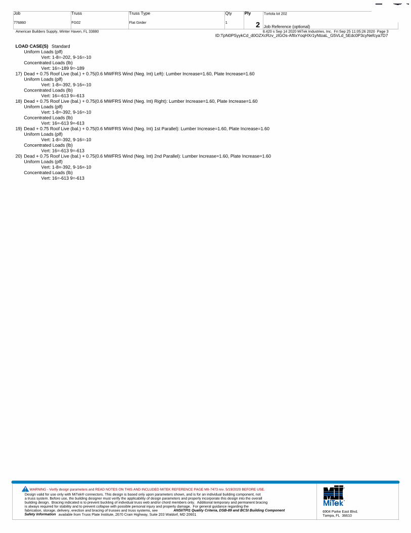
Design valid for use only with MiTek® connectors. This design is based only upon parameters shown, and is for an individual building component, not a truss system. Before use, the building designer must verify the applicability of design parameters and properly incorporate this design into the overall building design. Bracing indicated is to prevent buckling of individual truss web and/or chord members only. Additional temporary and permanent bracing is always required for stability and to prevent collapse with possible personal injury and property damage. For general guidance regarding the fabrication, storage, delivery, erection and bracing of trusses and truss systems, see ANSI/TPI1 Quality Criteria, DSB-89 and BCSI Building Component
available from Truss Plate Institute, 2670 Crain Highway, Suite 203 Waldorf, MD 20601Safety Information
WARNING - Verify design parameters and READ NOTES ON THIS AND INCLUDED MITEK REFERENCE PAGE MII-7473 rev. 5/19/2020 BEFORE USE.
6904 Parke East Blvd.Tampa, FL 36610
Job
776860
Truss
FG02
Truss Type
Flat Girder
Qty
1
Ply
2
Tortola lot 202
Job Reference (optional)
T21407511
8.420 s Sep 14 2020 MiTek Industries, Inc. Fri Sep 25 11:05:26 2020 Page 3 American Builders Supply, Winter Haven, FL 33880ID:TpN0PSyykCd_d0OZXcRzv_zlGOs-AftIxYoqHXr1yNtoaL_G5VLd_5Edc0P3cyNefcya7D7
LOAD CASE(S) StandardUniform Loads (plf)
Vert: 1-8=-202, 9-16=-10Concentrated Loads (lb)
Vert: 16=-189 9=-18917) Dead + 0.75 Roof Live (bal.) + 0.75(0.6 MWFRS Wind (Neg. Int) Left): Lumber Increase=1.60, Plate Increase=1.60
Uniform Loads (plf)Vert: 1-8=-392, 9-16=-10
Concentrated Loads (lb)Vert: 16=-613 9=-613
18) Dead + 0.75 Roof Live (bal.) + 0.75(0.6 MWFRS Wind (Neg. Int) Right): Lumber Increase=1.60, Plate Increase=1.60Uniform Loads (plf)
Vert: 1-8=-392, 9-16=-10Concentrated Loads (lb)
Vert: 16=-613 9=-61319) Dead + 0.75 Roof Live (bal.) + 0.75(0.6 MWFRS Wind (Neg. Int) 1st Parallel): Lumber Increase=1.60, Plate Increase=1.60
Uniform Loads (plf)Vert: 1-8=-392, 9-16=-10
Concentrated Loads (lb)Vert: 16=-613 9=-613
20) Dead + 0.75 Roof Live (bal.) + 0.75(0.6 MWFRS Wind (Neg. Int) 2nd Parallel): Lumber Increase=1.60, Plate Increase=1.60Uniform Loads (plf)
Vert: 1-8=-392, 9-16=-10Concentrated Loads (lb)
Vert: 16=-613 9=-613
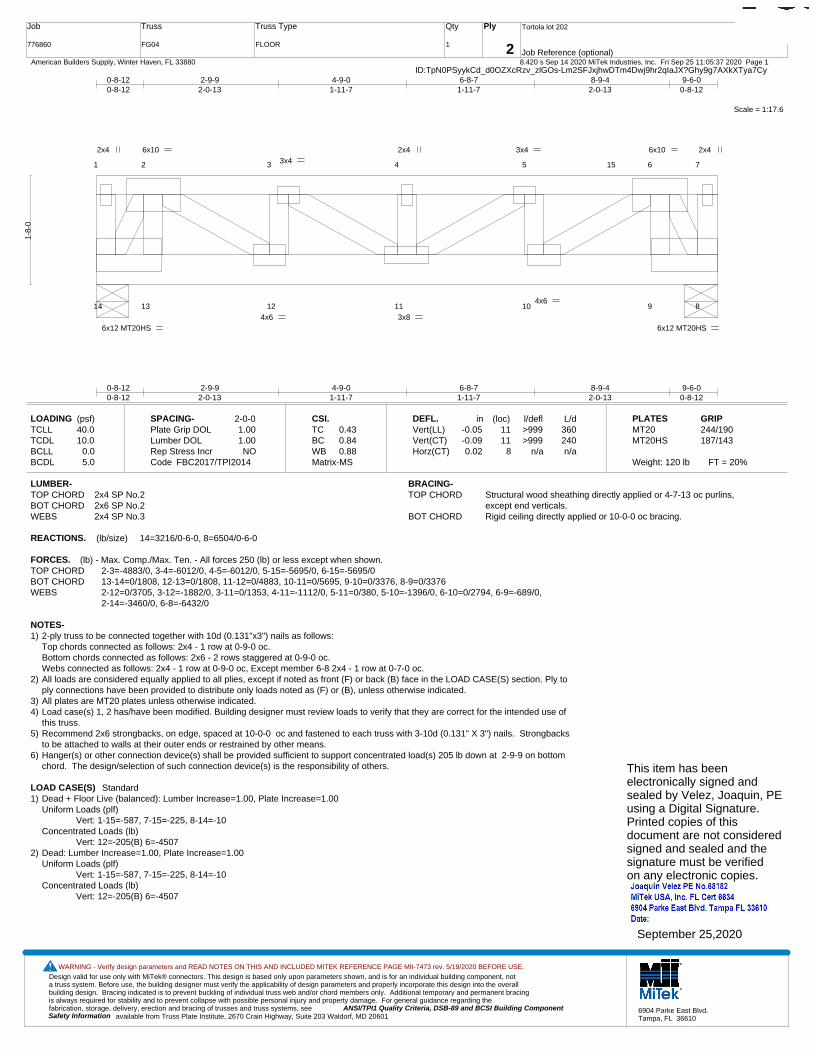
Design valid for use only with MiTek® connectors. This design is based only upon parameters shown, and is for an individual building component, not a truss system. Before use, the building designer must verify the applicability of design parameters and properly incorporate this design into the overall building design. Bracing indicated is to prevent buckling of individual truss web and/or chord members only. Additional temporary and permanent bracing is always required for stability and to prevent collapse with possible personal injury and property damage. For general guidance regarding the fabrication, storage, delivery, erection and bracing of trusses and truss systems, see ANSI/TPI1 Quality Criteria, DSB-89 and BCSI Building Component
available from Truss Plate Institute, 2670 Crain Highway, Suite 203 Waldorf, MD 20601Safety Information
WARNING - Verify design parameters and READ NOTES ON THIS AND INCLUDED MITEK REFERENCE PAGE MII-7473 rev. 5/19/2020 BEFORE USE.
6904 Parke East Blvd.Tampa, FL 36610
Job
776860
Truss
FG04
Truss Type
FLOOR
Qty
1
Ply
2
Tortola lot 202
Job Reference (optional)
T21407512
8.420 s Sep 14 2020 MiTek Industries, Inc. Fri Sep 25 11:05:37 2020 Page 1 American Builders Supply, Winter Haven, FL 33880ID:TpN0PSyykCd_d0OZXcRzv_zlGOs-Lm2SFJxjhwDTm4Dwj9hr2qIaJX?Ghy9g7AXkXTya7Cy
Scale = 1:17.6
1 2 3 4 5 6 7
14 13 12 11 10 9 8
15
6x12 MT20HS
2x4 2x4
6x12 MT20HS
6x10
4x6
3x4
3x8
2x4 3x4
4x6
6x10
0-8-120-8-12
2-9-92-0-13
4-9-01-11-7
6-8-71-11-7
8-9-42-0-13
9-6-00-8-12
0-8-120-8-12
2-9-92-0-13
4-9-01-11-7
6-8-71-11-7
8-9-42-0-13
9-6-00-8-12
1-8-
0
LOADING (psf)TCLLTCDLBCLLBCDL
40.010.0
0.05.0
SPACING-Plate Grip DOLLumber DOL Rep Stress IncrCode
2-0-01.001.00NO
FBC2017/TPI2014
CSI.TCBCWBMatrix-MS
0.430.840.88
DEFL.Vert(LL)Vert(CT)Horz(CT)
in-0.05-0.090.02
(loc)1111
8
l/defl>999>999
n/a
L/d360240n/a
PLATESMT20MT20HS
Weight: 120 lb FT = 20%
GRIP244/190187/143
LUMBER-TOP CHORD 2x4 SP No.2BOT CHORD 2x6 SP No.2WEBS 2x4 SP No.3
BRACING-TOP CHORD Structural wood sheathing directly applied or 4-7-13 oc purlins,
except end verticals.BOT CHORD Rigid ceiling directly applied or 10-0-0 oc bracing.
REACTIONS. (lb/size) 14=3216/0-6-0, 8=6504/0-6-0
FORCES. (lb) - Max. Comp./Max. Ten. - All forces 250 (lb) or less except when shown.TOP CHORD 2-3=-4883/0, 3-4=-6012/0, 4-5=-6012/0, 5-15=-5695/0, 6-15=-5695/0BOT CHORD 13-14=0/1808, 12-13=0/1808, 11-12=0/4883, 10-11=0/5695, 9-10=0/3376, 8-9=0/3376WEBS 2-12=0/3705, 3-12=-1882/0, 3-11=0/1353, 4-11=-1112/0, 5-11=0/380, 5-10=-1396/0, 6-10=0/2794, 6-9=-689/0,
2-14=-3460/0, 6-8=-6432/0
NOTES-1) 2-ply truss to be connected together with 10d (0.131"x3") nails as follows:
Top chords connected as follows: 2x4 - 1 row at 0-9-0 oc.Bottom chords connected as follows: 2x6 - 2 rows staggered at 0-9-0 oc.Webs connected as follows: 2x4 - 1 row at 0-9-0 oc, Except member 6-8 2x4 - 1 row at 0-7-0 oc.
2) All loads are considered equally applied to all plies, except if noted as front (F) or back (B) face in the LOAD CASE(S) section. Ply toply connections have been provided to distribute only loads noted as (F) or (B), unless otherwise indicated.
3) All plates are MT20 plates unless otherwise indicated. 4) Load case(s) 1, 2 has/have been modified. Building designer must review loads to verify that they are correct for the intended use of
this truss.5) Recommend 2x6 strongbacks, on edge, spaced at 10-0-0 oc and fastened to each truss with 3-10d (0.131" X 3") nails. Strongbacks
to be attached to walls at their outer ends or restrained by other means.6) Hanger(s) or other connection device(s) shall be provided sufficient to support concentrated load(s) 205 lb down at 2-9-9 on bottom
chord. The design/selection of such connection device(s) is the responsibility of others.
LOAD CASE(S) Standard1) Dead + Floor Live (balanced): Lumber Increase=1.00, Plate Increase=1.00
Uniform Loads (plf)Vert: 1-15=-587, 7-15=-225, 8-14=-10
Concentrated Loads (lb)Vert: 12=-205(B) 6=-4507
2) Dead: Lumber Increase=1.00, Plate Increase=1.00Uniform Loads (plf)
Vert: 1-15=-587, 7-15=-225, 8-14=-10Concentrated Loads (lb)
Vert: 12=-205(B) 6=-4507
This item has beenelectronically signed andsealed by Velez, Joaquin, PEusing a Digital Signature.Printed copies of thisdocument are not consideredsigned and sealed and thesignature must be verified on any electronic copies.
September 25,2020

Design valid for use only with MiTek® connectors. This design is based only upon parameters shown, and is for an individual building component, not a truss system. Before use, the building designer must verify the applicability of design parameters and properly incorporate this design into the overall building design. Bracing indicated is to prevent buckling of individual truss web and/or chord members only. Additional temporary and permanent bracing is always required for stability and to prevent collapse with possible personal injury and property damage. For general guidance regarding the fabrication, storage, delivery, erection and bracing of trusses and truss systems, see ANSI/TPI1 Quality Criteria, DSB-89 and BCSI Building Component
available from Truss Plate Institute, 2670 Crain Highway, Suite 203 Waldorf, MD 20601Safety Information
WARNING - Verify design parameters and READ NOTES ON THIS AND INCLUDED MITEK REFERENCE PAGE MII-7473 rev. 5/19/2020 BEFORE USE.
6904 Parke East Blvd.Tampa, FL 36610
Job
776860
Truss
FT01
Truss Type
Floor
Qty
8
Ply
1
Tortola lot 202
Job Reference (optional)
T21407513
8.420 s Aug 25 2020 MiTek Industries, Inc. Fri Sep 25 09:23:11 2020 Page 1 American Builders Supply, Winter Haven, FL 33880ID:TpN0PSyykCd_d0OZXcRzv_zlGOs-feF2xuFlI4GYd3cqIjgf?grSrD5u9W3wh3o0A1ya7qk
Scale = 1:34.6
1 2 3 4 5 6 7 8 9 10 11
18 17 16 15 14 13 12
19
20
21
22
3x10 MT20HS FP 3x6
3x6 FP
3x4 3x4 3x6
4x6
4x8
4x4 4x6
4x8
4x4
0-3-
8
0-3-
8
9-5-129-5-12
9-7-40-1-8
10-7-4
1-0-011-7-41-0-0
11-8-12
0-1-821-2-89-5-12
2-6-0 1-7-4 2-0-0 1-7-4
0-1-8
0-1-8
1-8-
0
1-8-
0
Plate Offsets (X,Y)-- [5:0-1-8,Edge], [6:0-1-8,0-0-0], [11:0-1-8,Edge], [14:0-1-8,Edge], [15:0-1-8,Edge], [19:0-1-8,0-1-0], [20:0-1-8,0-1-0], [21:0-1-8,0-1-0], [22:0-1-8,0-1-0]
LOADING (psf)TCLLTCDLBCLLBCDL
40.010.0
0.05.0
SPACING-Plate Grip DOLLumber DOL Rep Stress IncrCode
2-0-01.001.00YES
FBC2017/TPI2014
CSI.TCBCWBMatrix-S
0.550.690.68
DEFL.Vert(LL)Vert(CT)Horz(CT)
in-0.30-0.390.08
(loc)13-1413-14
12
l/defl>845>635
n/a
L/d360240n/a
PLATESMT20MT20HS
Weight: 110 lb FT = 20%F, 11%E
GRIP244/190187/143
LUMBER-TOP CHORD 2x4 SP M 30(flat) *Except*
8-11: 2x4 SP No.2(flat)BOT CHORD 2x4 SP M 30(flat)WEBS 2x4 SP No.3(flat)
BRACING-TOP CHORD Structural wood sheathing directly applied or 6-0-0 oc purlins,
except end verticals.BOT CHORD Rigid ceiling directly applied or 10-0-0 oc bracing.
REACTIONS. (size) 12=0-7-4, 18=0-7-4Max Grav 12=1146(LC 1), 18=1146(LC 1)
FORCES. (lb) - Max. Comp./Max. Ten. - All forces 250 (lb) or less except when shown.TOP CHORD 2-3=-2917/0, 3-4=-2917/0, 4-5=-3833/0, 5-6=-3844/0, 6-7=-3834/0, 7-9=-2916/0,
9-10=-2916/0BOT CHORD 17-18=0/1697, 15-17=0/3624, 14-15=0/3844, 13-14=0/3626, 12-13=0/1698WEBS 5-15=-343/25, 6-14=-341/27, 2-18=-1981/0, 2-17=0/1423, 3-17=-257/0, 4-17=-823/0,
4-15=-97/624, 10-12=-1981/0, 10-13=0/1422, 9-13=-255/0, 7-13=-827/0, 7-14=-99/622
NOTES-1) Unbalanced floor live loads have been considered for this design.2) All plates are MT20 plates unless otherwise indicated. 3) All plates are 2x4 MT20 unless otherwise indicated.4) Recommend 2x6 strongbacks, on edge, spaced at 10-0-0 oc and fastened to each truss with 3-10d (0.131" X 3") nails.
Strongbacks to be attached to walls at their outer ends or restrained by other means.
This item has beenelectronically signed andsealed by Velez, Joaquin, PEusing a Digital Signature.Printed copies of thisdocument are not consideredsigned and sealed and thesignature must be verified on any electronic copies.
September 25,2020
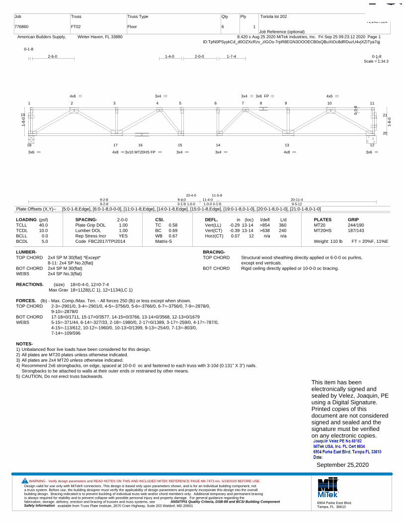
Design valid for use only with MiTek® connectors. This design is based only upon parameters shown, and is for an individual building component, not a truss system. Before use, the building designer must verify the applicability of design parameters and properly incorporate this design into the overall building design. Bracing indicated is to prevent buckling of individual truss web and/or chord members only. Additional temporary and permanent bracing is always required for stability and to prevent collapse with possible personal injury and property damage. For general guidance regarding the fabrication, storage, delivery, erection and bracing of trusses and truss systems, see ANSI/TPI1 Quality Criteria, DSB-89 and BCSI Building Component
available from Truss Plate Institute, 2670 Crain Highway, Suite 203 Waldorf, MD 20601Safety Information
WARNING - Verify design parameters and READ NOTES ON THIS AND INCLUDED MITEK REFERENCE PAGE MII-7473 rev. 5/19/2020 BEFORE USE.
6904 Parke East Blvd.Tampa, FL 36610
Job
776860
Truss
FT02
Truss Type
Floor
Qty
6
Ply
1
Tortola lot 202
Job Reference (optional)
T21407514
8.420 s Aug 25 2020 MiTek Industries, Inc. Fri Sep 25 09:23:12 2020 Page 1 American Builders Supply, Winter Haven, FL 33880ID:TpN0PSyykCd_d0OZXcRzv_zlGOs-7rpR8EGN3OOOECB0sQBuXtOc8dRDuzU4vjXZiTya7qj
Scale = 1:34.3
1 2 3 4 5 6 7 8 9 10 11
18 17 16 15 14 13 12
19
20
21
3x10 MT20HS FP3x6 3x6
3x6 FP
3x4 3x4
4x6
4x8
3x4 4x6
4x8
3x4
0-3-
8
9-2-89-2-8
9-4-00-1-8
10-4-0
1-0-011-4-01-0-0
11-5-8
0-1-820-11-49-5-12
2-6-0 1-4-0 2-0-0 1-7-4
0-1-8
0-1-8
1-8-
0
1-8-
0
Plate Offsets (X,Y)-- [5:0-1-8,Edge], [6:0-1-8,0-0-0], [11:0-1-8,Edge], [14:0-1-8,Edge], [15:0-1-8,Edge], [19:0-1-8,0-1-0], [20:0-1-8,0-1-0], [21:0-1-8,0-1-0]
LOADING (psf)TCLLTCDLBCLLBCDL
40.010.0
0.05.0
SPACING-Plate Grip DOLLumber DOL Rep Stress IncrCode
2-0-01.001.00YES
FBC2017/TPI2014
CSI.TCBCWBMatrix-S
0.580.690.67
DEFL.Vert(LL)Vert(CT)Horz(CT)
in-0.29-0.390.07
(loc)13-1413-14
12
l/defl>854>638
n/a
L/d360240n/a
PLATESMT20MT20HS
Weight: 110 lb FT = 20%F, 11%E
GRIP244/190187/143
LUMBER-TOP CHORD 2x4 SP M 30(flat) *Except*
8-11: 2x4 SP No.2(flat)BOT CHORD 2x4 SP M 30(flat)WEBS 2x4 SP No.3(flat)
BRACING-TOP CHORD Structural wood sheathing directly applied or 6-0-0 oc purlins,
except end verticals.BOT CHORD Rigid ceiling directly applied or 10-0-0 oc bracing.
REACTIONS. (size) 18=0-4-0, 12=0-7-4Max Grav 18=1128(LC 1), 12=1134(LC 1)
FORCES. (lb) - Max. Comp./Max. Ten. - All forces 250 (lb) or less except when shown.TOP CHORD 2-3=-2901/0, 3-4=-2901/0, 4-5=-3756/0, 5-6=-3766/0, 6-7=-3756/0, 7-9=-2878/0,
9-10=-2878/0BOT CHORD 17-18=0/1711, 15-17=0/3577, 14-15=0/3766, 13-14=0/3568, 12-13=0/1679WEBS 5-15=-371/44, 6-14=-327/33, 2-18=-1980/0, 2-17=0/1389, 3-17=-259/0, 4-17=-787/0,
4-15=-113/612, 10-12=-1960/0, 10-13=0/1399, 9-13=-254/0, 7-13=-803/0, 7-14=-109/596
NOTES-1) Unbalanced floor live loads have been considered for this design.2) All plates are MT20 plates unless otherwise indicated. 3) All plates are 2x4 MT20 unless otherwise indicated.4) Recommend 2x6 strongbacks, on edge, spaced at 10-0-0 oc and fastened to each truss with 3-10d (0.131" X 3") nails.
Strongbacks to be attached to walls at their outer ends or restrained by other means.5) CAUTION, Do not erect truss backwards.
This item has beenelectronically signed andsealed by Velez, Joaquin, PEusing a Digital Signature.Printed copies of thisdocument are not consideredsigned and sealed and thesignature must be verified on any electronic copies.
September 25,2020
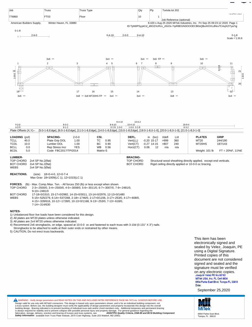
Design valid for use only with MiTek® connectors. This design is based only upon parameters shown, and is for an individual building component, not a truss system. Before use, the building designer must verify the applicability of design parameters and properly incorporate this design into the overall building design. Bracing indicated is to prevent buckling of individual truss web and/or chord members only. Additional temporary and permanent bracing is always required for stability and to prevent collapse with possible personal injury and property damage. For general guidance regarding the fabrication, storage, delivery, erection and bracing of trusses and truss systems, see ANSI/TPI1 Quality Criteria, DSB-89 and BCSI Building Component
available from Truss Plate Institute, 2670 Crain Highway, Suite 203 Waldorf, MD 20601Safety Information
WARNING - Verify design parameters and READ NOTES ON THIS AND INCLUDED MITEK REFERENCE PAGE MII-7473 rev. 5/19/2020 BEFORE USE.
6904 Parke East Blvd.Tampa, FL 36610
Job
776860
Truss
FT03
Truss Type
Floor
Qty
10
Ply
1
Tortola lot 202
Job Reference (optional)
T21407515
8.420 s Aug 25 2020 MiTek Industries, Inc. Fri Sep 25 09:23:12 2020 Page 1 American Builders Supply, Winter Haven, FL 33880ID:TpN0PSyykCd_d0OZXcRzv_zlGOs-7rpR8EGN3OOOECB0sQBuXtOXLdNru?C4vjXZiTya7qj
Scale = 1:30.8
1 2 3 4 5 6 7 8 9 10 11
18 17 16 15 14 13 12
19
20
21
3x8 MT20HS FP3x6 3x4
3x6 FP
3x4 3x4
3x6
3x8
3x4 3x6
3x8
3x4
0-3-
8
0-2-00-2-0
8-3-28-1-2
8-4-100-1-8
9-4-10
1-0-010-4-10
1-0-0
10-6-2
0-1-818-9-48-3-2
2-6-0 0-4-10 2-0-0 0-4-10
0-1-8
0-1-8
1-8-
0
1-8-
0
Plate Offsets (X,Y)-- [5:0-1-8,Edge], [6:0-1-8,Edge], [11:0-1-8,Edge], [14:0-1-8,Edge], [15:0-1-8,Edge], [19:0-1-8,0-1-0], [20:0-1-8,0-1-0], [21:0-1-8,0-1-0]
LOADING (psf)TCLLTCDLBCLLBCDL
40.010.0
0.05.0
SPACING-Plate Grip DOLLumber DOL Rep Stress IncrCode
2-0-01.001.00YES
FBC2017/TPI2014
CSI.TCBCWBMatrix-S
0.950.900.56
DEFL.Vert(LL)Vert(CT)Horz(CT)
in-0.20-0.270.06
(loc)15-1714-15
12
l/defl>999>807
n/a
L/d360240n/a
PLATESMT20MT20HS
Weight: 101 lb FT = 20%F, 11%E
GRIP244/190187/143
LUMBER-TOP CHORD 2x4 SP No.2(flat)BOT CHORD 2x4 SP No.2(flat)WEBS 2x4 SP No.3(flat)
BRACING-TOP CHORD Structural wood sheathing directly applied, except end verticals.BOT CHORD Rigid ceiling directly applied or 10-0-0 oc bracing.
REACTIONS. (size) 18=0-4-0, 12=0-7-4Max Grav 18=1009(LC 1), 12=1015(LC 1)
FORCES. (lb) - Max. Comp./Max. Ten. - All forces 250 (lb) or less except when shown.TOP CHORD 2-3=-2500/0, 3-4=-2500/0, 4-5=-3008/0, 5-6=-3011/0, 6-7=-3007/0, 7-9=-2481/0,
9-10=-2481/0BOT CHORD 17-18=0/1510, 15-17=0/2982, 14-15=0/3011, 13-14=0/2976, 12-13=0/1480WEBS 5-15=-525/279, 6-14=-537/268, 2-18=-1746/0, 2-17=0/1156, 3-17=-253/0, 4-17=-608/0,
4-15=-328/616, 10-12=-1728/0, 10-13=0/1168, 9-13=-253/0, 7-13=-618/0, 7-14=-314/630
NOTES-1) Unbalanced floor live loads have been considered for this design.2) All plates are MT20 plates unless otherwise indicated. 3) All plates are 2x4 MT20 unless otherwise indicated.4) Recommend 2x6 strongbacks, on edge, spaced at 10-0-0 oc and fastened to each truss with 3-10d (0.131" X 3") nails.
Strongbacks to be attached to walls at their outer ends or restrained by other means.5) CAUTION, Do not erect truss backwards.
This item has beenelectronically signed andsealed by Velez, Joaquin, PEusing a Digital Signature.Printed copies of thisdocument are not consideredsigned and sealed and thesignature must be verified on any electronic copies.
September 25,2020

Design valid for use only with MiTek® connectors. This design is based only upon parameters shown, and is for an individual building component, not a truss system. Before use, the building designer must verify the applicability of design parameters and properly incorporate this design into the overall building design. Bracing indicated is to prevent buckling of individual truss web and/or chord members only. Additional temporary and permanent bracing is always required for stability and to prevent collapse with possible personal injury and property damage. For general guidance regarding the fabrication, storage, delivery, erection and bracing of trusses and truss systems, see ANSI/TPI1 Quality Criteria, DSB-89 and BCSI Building Component
available from Truss Plate Institute, 2670 Crain Highway, Suite 203 Waldorf, MD 20601Safety Information
WARNING - Verify design parameters and READ NOTES ON THIS AND INCLUDED MITEK REFERENCE PAGE MII-7473 rev. 5/19/2020 BEFORE USE.
6904 Parke East Blvd.Tampa, FL 36610
Job
776860
Truss
FT04
Truss Type
Floor
Qty
3
Ply
1
Tortola lot 202
Job Reference (optional)
T21407516
8.420 s Aug 25 2020 MiTek Industries, Inc. Fri Sep 25 09:23:13 2020 Page 1 American Builders Supply, Winter Haven, FL 33880ID:TpN0PSyykCd_d0OZXcRzv_zlGOs-c1NpMaG?qhWFsMmDP7j745wl21kGdSVD8NH7Ewya7qi
Scale = 1:30.8
1 2 3 4 5 6 7 8 9 10 11
18 17 16 15 14 13 12
19
20
21
22
3x8 MT20HS FP 3x4
3x6 FP
3x4 3x4 3x4
3x6
3x8
3x4 3x6
3x8
3x4
0-3-
8
0-3-
8
8-3-28-3-2
8-4-100-1-8
9-4-10
1-0-010-4-10
1-0-0
10-6-2
0-1-818-9-48-3-2
2-6-0 0-4-10 2-0-0 0-4-10
0-1-8
0-1-8
1-8-
0
1-8-
0
Plate Offsets (X,Y)-- [5:0-1-8,Edge], [6:0-1-8,Edge], [11:0-1-8,Edge], [14:0-1-8,Edge], [15:0-1-8,Edge], [19:0-1-8,0-1-0], [20:0-1-8,0-1-0], [21:0-1-8,0-1-0], [22:0-1-8,0-1-0]
LOADING (psf)TCLLTCDLBCLLBCDL
40.010.0
0.05.0
SPACING-Plate Grip DOLLumber DOL Rep Stress IncrCode
2-0-01.001.00YES
FBC2017/TPI2014
CSI.TCBCWBMatrix-S
0.770.890.55
DEFL.Vert(LL)Vert(CT)Horz(CT)
in-0.20-0.270.06
(loc)13-1414-15
12
l/defl>999>816
n/a
L/d360240n/a
PLATESMT20MT20HS
Weight: 101 lb FT = 20%F, 11%E
GRIP244/190187/143
LUMBER-TOP CHORD 2x4 SP No.2(flat)BOT CHORD 2x4 SP No.2(flat)WEBS 2x4 SP No.3(flat)
BRACING-TOP CHORD Structural wood sheathing directly applied or 5-10-6 oc purlins,
except end verticals.BOT CHORD Rigid ceiling directly applied or 10-0-0 oc bracing.
REACTIONS. (size) 12=0-7-4, 18=0-6-0Max Grav 12=1012(LC 1), 18=1012(LC 1)
FORCES. (lb) - Max. Comp./Max. Ten. - All forces 250 (lb) or less except when shown.TOP CHORD 2-3=-2470/0, 3-4=-2470/0, 4-5=-2987/0, 5-6=-2991/0, 6-7=-2987/0, 7-9=-2470/0,
9-10=-2470/0BOT CHORD 17-18=0/1475, 15-17=0/2959, 14-15=0/2991, 13-14=0/2959, 12-13=0/1475WEBS 5-15=-529/272, 6-14=-529/272, 2-18=-1721/0, 2-17=0/1161, 3-17=-253/0, 4-17=-612/0,
4-15=-319/621, 10-12=-1721/0, 10-13=0/1161, 9-13=-253/0, 7-13=-612/0, 7-14=-319/621
NOTES-1) Unbalanced floor live loads have been considered for this design.2) All plates are MT20 plates unless otherwise indicated. 3) All plates are 2x4 MT20 unless otherwise indicated.4) Recommend 2x6 strongbacks, on edge, spaced at 10-0-0 oc and fastened to each truss with 3-10d (0.131" X 3") nails.
Strongbacks to be attached to walls at their outer ends or restrained by other means.
This item has beenelectronically signed andsealed by Velez, Joaquin, PEusing a Digital Signature.Printed copies of thisdocument are not consideredsigned and sealed and thesignature must be verified on any electronic copies.
September 25,2020
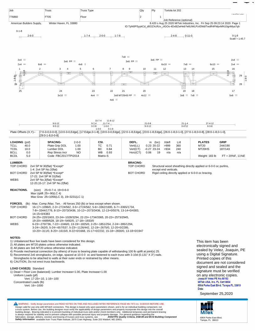
Design valid for use only with MiTek® connectors. This design is based only upon parameters shown, and is for an individual building component, not a truss system. Before use, the building designer must verify the applicability of design parameters and properly incorporate this design into the overall building design. Bracing indicated is to prevent buckling of individual truss web and/or chord members only. Additional temporary and permanent bracing is always required for stability and to prevent collapse with possible personal injury and property damage. For general guidance regarding the fabrication, storage, delivery, erection and bracing of trusses and truss systems, see ANSI/TPI1 Quality Criteria, DSB-89 and BCSI Building Component
available from Truss Plate Institute, 2670 Crain Highway, Suite 203 Waldorf, MD 20601Safety Information
WARNING - Verify design parameters and READ NOTES ON THIS AND INCLUDED MITEK REFERENCE PAGE MII-7473 rev. 5/19/2020 BEFORE USE.
6904 Parke East Blvd.Tampa, FL 36610
Job
776860
Truss
FT05
Truss Type
Floor
Qty
2
Ply
1
Tortola lot 202
Job Reference (optional)
T21407517
8.420 s Aug 25 2020 MiTek Industries, Inc. Fri Sep 25 09:23:14 2020 Page 1 American Builders Supply, Winter Haven, FL 33880ID:TpN0PSyykCd_d0OZXcRzv_zlGOs-4DxBZwHeb?e6UWLPzrEMdITwdR4FMpvMN10gnMya7qh
Scale = 1:45.7
1 2 3 4 5 6 7 8 9 10 11 12 13 14 15 16
25 24 23 22 21 20 19 18 17
26
27
28
29
3x8 MT20HS FP
2x4
2x4
2x4
2x4
5x6
3x6 FP
4x4
4x6
7x8 6x6
3x10
4x6
3x8
6x10
4x12
7x8
6x10
7x8
3x6 FP3x6 FP
0-3-
8
0-3-
8
9-5-129-5-12
9-7-40-1-8
10-7-4
1-0-0
11-7-41-0-0
11-8-12
0-1-8
21-0-89-3-12
21-1-40-0-12
27-4-126-3-8
2-6-0 1-7-4 2-0-0 1-7-8 2-4-8 0-11-0
0-1-8
0-1-8
1-8-
0
1-8-
0
Plate Offsets (X,Y)-- [7:0-3-0,0-0-0], [13:0-3-0,Edge], [17:Edge,0-1-8], [19:0-3-0,Edge], [22:0-1-8,Edge], [23:0-1-8,Edge], [26:0-1-8,0-1-0], [27:0-1-8,0-0-8], [28:0-1-8,0-1-0],[29:0-1-8,0-0-8]
LOADING (psf)TCLLTCDLBCLLBCDL
40.010.0
0.05.0
SPACING-Plate Grip DOLLumber DOL Rep Stress IncrCode
2-0-01.001.00NO
FBC2017/TPI2014
CSI.TCBCWBMatrix-S
0.710.840.93
DEFL.Vert(LL)Vert(CT)Horz(CT)
in0.23
-0.270.06
(loc)20-2223-24
19
l/defl>999>934
n/a
L/d360240n/a
PLATESMT20MT20HS
Weight: 183 lb FT = 20%F, 11%E
GRIP244/190187/143
LUMBER-TOP CHORD 2x4 SP M 30(flat) *Except*
1-4: 2x4 SP No.2(flat)BOT CHORD 2x4 SP M 30(flat) *Except*
17-21: 2x4 SP M 31(flat)WEBS 2x4 SP No.3(flat) *Except*
12-20,15-17: 2x4 SP No.2(flat)
BRACING-TOP CHORD Structural wood sheathing directly applied or 6-0-0 oc purlins,
except end verticals.BOT CHORD Rigid ceiling directly applied or 6-0-0 oc bracing.
REACTIONS. (size) 25=0-7-4, 19=0-6-0Max Uplift 25=-90(LC 4)Max Grav 25=1056(LC 3), 19=3231(LC 1)
FORCES. (lb) - Max. Comp./Max. Ten. - All forces 250 (lb) or less except when shown.TOP CHORD 16-17=-1096/0, 2-3=-2724/562, 3-5=-2724/562, 5-6=-3362/1695, 6-7=-3365/1734,
7-8=-3344/1776, 8-10=-2073/3436, 10-12=-2073/3436, 12-13=0/5576, 13-14=0/4383, 14-15=0/4383
BOT CHORD 24-25=-220/1603, 23-24=-1028/3294, 22-23=-1734/3365, 20-22=-2573/2945, 19-20=-4489/628, 18-19=-5492/0, 17-18=-1933/0
WEBS 6-23=-270/736, 7-22=-1046/0, 13-19=-1825/0, 2-25=-1851/254, 2-24=-395/1294, 3-24=-262/0, 5-24=-657/537, 5-23=-1126/442, 12-19=-2675/0, 12-20=0/2285, 10-20=-311/0, 8-20=-1615/0, 8-22=0/1668, 15-17=0/2232, 15-18=-2830/0, 13-18=0/1947
NOTES-1) Unbalanced floor live loads have been considered for this design.2) All plates are MT20 plates unless otherwise indicated. 3) All plates are 3x6 MT20 unless otherwise indicated.4) Provide mechanical connection (by others) of truss to bearing plate capable of withstanding 100 lb uplift at joint(s) 25.5) Recommend 2x6 strongbacks, on edge, spaced at 10-0-0 oc and fastened to each truss with 3-10d (0.131" X 3") nails.
Strongbacks to be attached to walls at their outer ends or restrained by other means.6) CAUTION, Do not erect truss backwards.
LOAD CASE(S) Standard1) Dead + Floor Live (balanced): Lumber Increase=1.00, Plate Increase=1.00
Uniform Loads (plf)Vert: 17-25=-10, 1-16=-100
Concentrated Loads (lb)Vert: 16=-1000
This item has beenelectronically signed andsealed by Velez, Joaquin, PEusing a Digital Signature.Printed copies of thisdocument are not consideredsigned and sealed and thesignature must be verified on any electronic copies.
September 25,2020
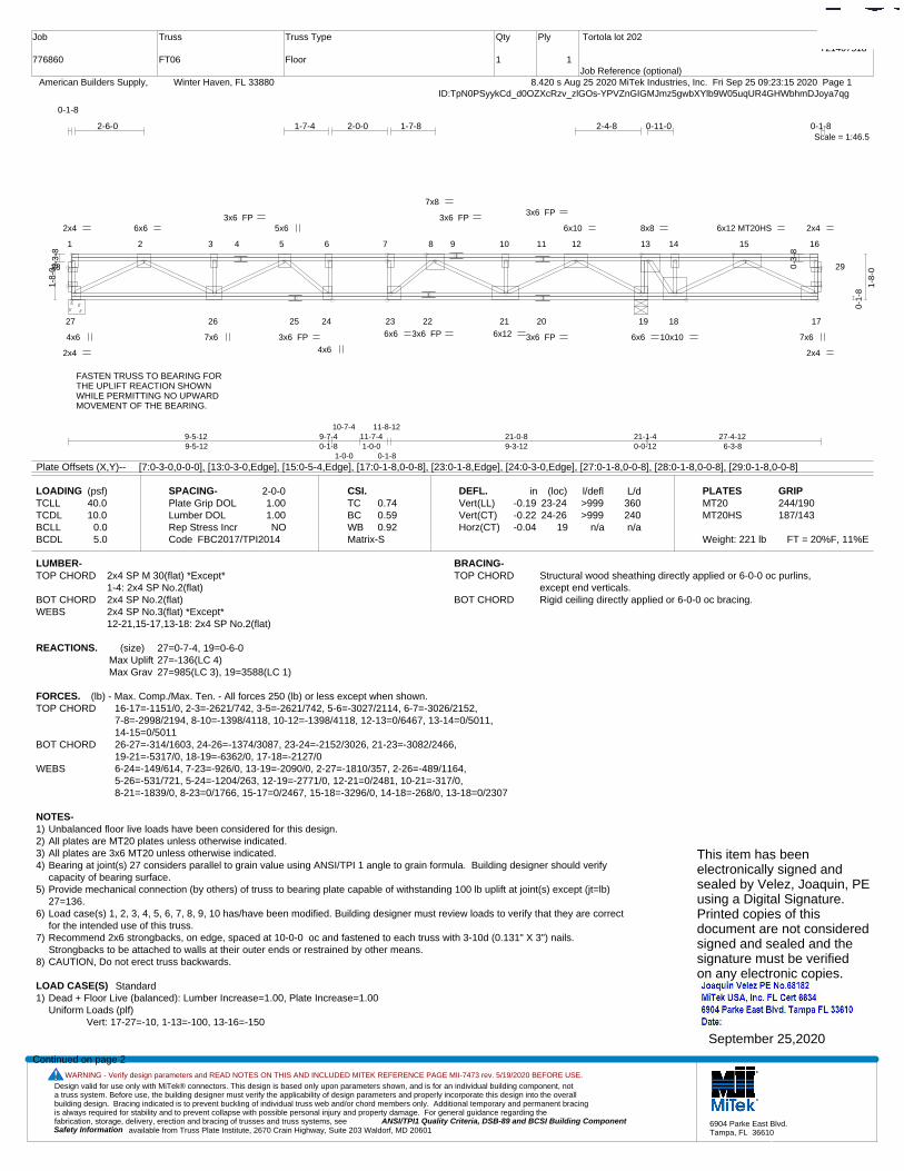
Design valid for use only with MiTek® connectors. This design is based only upon parameters shown, and is for an individual building component, not a truss system. Before use, the building designer must verify the applicability of design parameters and properly incorporate this design into the overall building design. Bracing indicated is to prevent buckling of individual truss web and/or chord members only. Additional temporary and permanent bracing is always required for stability and to prevent collapse with possible personal injury and property damage. For general guidance regarding the fabrication, storage, delivery, erection and bracing of trusses and truss systems, see ANSI/TPI1 Quality Criteria, DSB-89 and BCSI Building Component
available from Truss Plate Institute, 2670 Crain Highway, Suite 203 Waldorf, MD 20601Safety Information
WARNING - Verify design parameters and READ NOTES ON THIS AND INCLUDED MITEK REFERENCE PAGE MII-7473 rev. 5/19/2020 BEFORE USE.
6904 Parke East Blvd.Tampa, FL 36610
Job
776860
Truss
FT06
Truss Type
Floor
Qty
1
Ply
1
Tortola lot 202
Job Reference (optional)
T21407518
8.420 s Aug 25 2020 MiTek Industries, Inc. Fri Sep 25 09:23:15 2020 Page 1 American Builders Supply, Winter Haven, FL 33880ID:TpN0PSyykCd_d0OZXcRzv_zlGOs-YPVZnGIGMJmz5gwbXYlb9W05uqUR4GHWbhmDJoya7qg
Scale = 1:46.5
1 2 3 4 5 6 7 8 9 10 11 12 13 14 15 16
27 26 25 24 23 22 21 20 19 18 17
28 29
3x6 FP
2x4
4x6
2x4
2x4
7x6
2x4
3x6 FP
4x6
6x6
8x8 6x6
7x6
5x6
6x6
6x10
6x12
7x8
6x12 MT20HS
10x10
3x6 FP
3x6 FP 3x6 FP
3x6 FP
0-3-
8
0-3-
8
9-5-129-5-12
9-7-40-1-8
10-7-4
1-0-0
11-7-41-0-0
11-8-12
0-1-8
21-0-89-3-12
21-1-40-0-12
27-4-126-3-8
2-6-0 1-7-4 2-0-0 1-7-8 2-4-8 0-11-0
0-1-8
0-1-8
1-8-
0
0-1-
8
1-8-
0
Plate Offsets (X,Y)-- [7:0-3-0,0-0-0], [13:0-3-0,Edge], [15:0-5-4,Edge], [17:0-1-8,0-0-8], [23:0-1-8,Edge], [24:0-3-0,Edge], [27:0-1-8,0-0-8], [28:0-1-8,0-0-8], [29:0-1-8,0-0-8]
LOADING (psf)TCLLTCDLBCLLBCDL
40.010.0
0.05.0
SPACING-Plate Grip DOLLumber DOL Rep Stress IncrCode
2-0-01.001.00NO
FBC2017/TPI2014
CSI.TCBCWBMatrix-S
0.740.590.92
DEFL.Vert(LL)Vert(CT)Horz(CT)
in-0.19-0.22-0.04
(loc)23-2424-26
19
l/defl>999>999
n/a
L/d360240n/a
PLATESMT20MT20HS
Weight: 221 lb FT = 20%F, 11%E
GRIP244/190187/143
LUMBER-TOP CHORD 2x4 SP M 30(flat) *Except*
1-4: 2x4 SP No.2(flat)BOT CHORD 2x4 SP No.2(flat)WEBS 2x4 SP No.3(flat) *Except*
12-21,15-17,13-18: 2x4 SP No.2(flat)
BRACING-TOP CHORD Structural wood sheathing directly applied or 6-0-0 oc purlins,
except end verticals.BOT CHORD Rigid ceiling directly applied or 6-0-0 oc bracing.
REACTIONS. (size) 27=0-7-4, 19=0-6-0Max Uplift 27=-136(LC 4)Max Grav 27=985(LC 3), 19=3588(LC 1)
FORCES. (lb) - Max. Comp./Max. Ten. - All forces 250 (lb) or less except when shown.TOP CHORD 16-17=-1151/0, 2-3=-2621/742, 3-5=-2621/742, 5-6=-3027/2114, 6-7=-3026/2152,
7-8=-2998/2194, 8-10=-1398/4118, 10-12=-1398/4118, 12-13=0/6467, 13-14=0/5011, 14-15=0/5011
BOT CHORD 26-27=-314/1603, 24-26=-1374/3087, 23-24=-2152/3026, 21-23=-3082/2466, 19-21=-5317/0, 18-19=-6362/0, 17-18=-2127/0
WEBS 6-24=-149/614, 7-23=-926/0, 13-19=-2090/0, 2-27=-1810/357, 2-26=-489/1164, 5-26=-531/721, 5-24=-1204/263, 12-19=-2771/0, 12-21=0/2481, 10-21=-317/0, 8-21=-1839/0, 8-23=0/1766, 15-17=0/2467, 15-18=-3296/0, 14-18=-268/0, 13-18=0/2307
NOTES-1) Unbalanced floor live loads have been considered for this design.2) All plates are MT20 plates unless otherwise indicated. 3) All plates are 3x6 MT20 unless otherwise indicated.4) Bearing at joint(s) 27 considers parallel to grain value using ANSI/TPI 1 angle to grain formula. Building designer should verify
capacity of bearing surface.5) Provide mechanical connection (by others) of truss to bearing plate capable of withstanding 100 lb uplift at joint(s) except (jt=lb)
27=136.6) Load case(s) 1, 2, 3, 4, 5, 6, 7, 8, 9, 10 has/have been modified. Building designer must review loads to verify that they are correct
for the intended use of this truss.7) Recommend 2x6 strongbacks, on edge, spaced at 10-0-0 oc and fastened to each truss with 3-10d (0.131" X 3") nails.
Strongbacks to be attached to walls at their outer ends or restrained by other means.8) CAUTION, Do not erect truss backwards.
LOAD CASE(S) Standard1) Dead + Floor Live (balanced): Lumber Increase=1.00, Plate Increase=1.00
Uniform Loads (plf)Vert: 17-27=-10, 1-13=-100, 13-16=-150
Continued on page 2
FASTEN TRUSS TO BEARING FORTHE UPLIFT REACTION SHOWNWHILE PERMITTING NO UPWARD MOVEMENT OF THE BEARING.
This item has beenelectronically signed andsealed by Velez, Joaquin, PEusing a Digital Signature.Printed copies of thisdocument are not consideredsigned and sealed and thesignature must be verified on any electronic copies.
September 25,2020
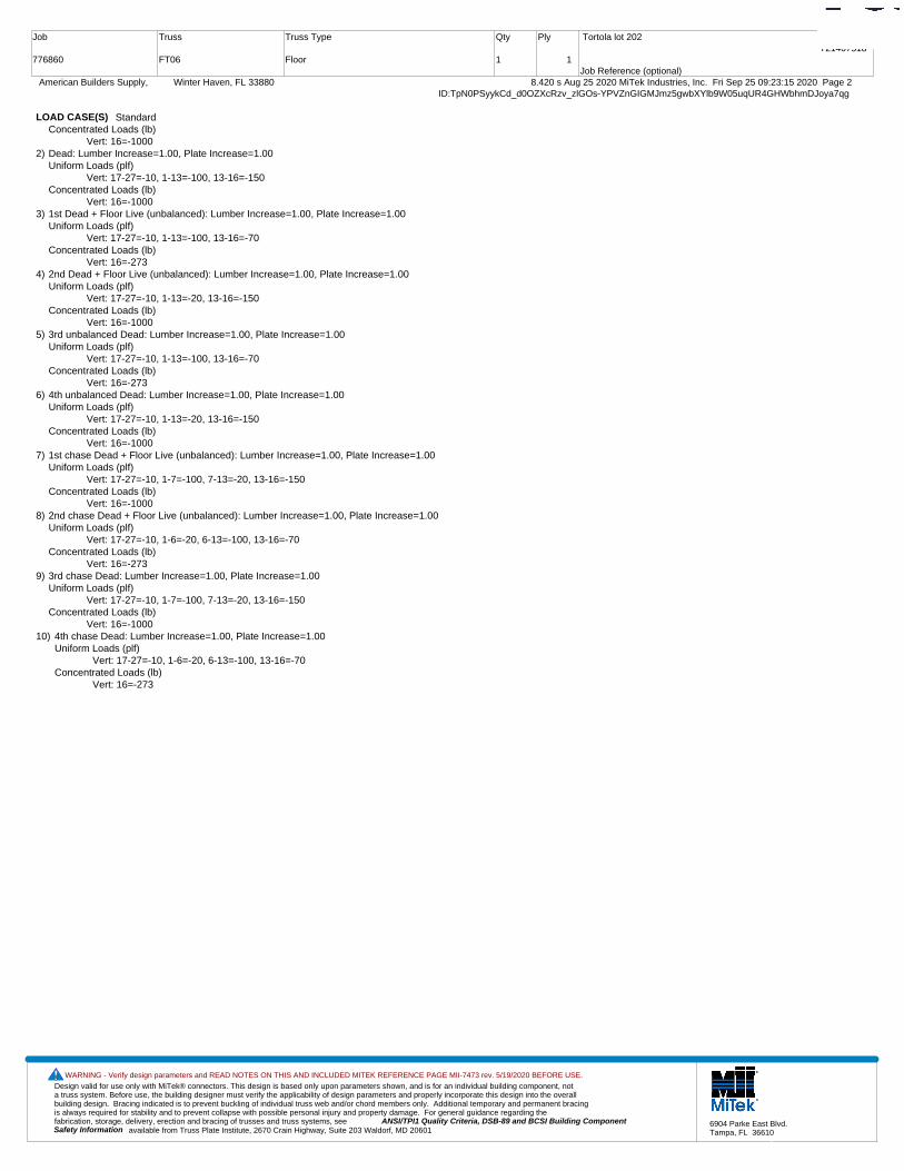
Design valid for use only with MiTek® connectors. This design is based only upon parameters shown, and is for an individual building component, not a truss system. Before use, the building designer must verify the applicability of design parameters and properly incorporate this design into the overall building design. Bracing indicated is to prevent buckling of individual truss web and/or chord members only. Additional temporary and permanent bracing is always required for stability and to prevent collapse with possible personal injury and property damage. For general guidance regarding the fabrication, storage, delivery, erection and bracing of trusses and truss systems, see ANSI/TPI1 Quality Criteria, DSB-89 and BCSI Building Component
available from Truss Plate Institute, 2670 Crain Highway, Suite 203 Waldorf, MD 20601Safety Information
WARNING - Verify design parameters and READ NOTES ON THIS AND INCLUDED MITEK REFERENCE PAGE MII-7473 rev. 5/19/2020 BEFORE USE.
6904 Parke East Blvd.Tampa, FL 36610
Job
776860
Truss
FT06
Truss Type
Floor
Qty
1
Ply
1
Tortola lot 202
Job Reference (optional)
T21407518
8.420 s Aug 25 2020 MiTek Industries, Inc. Fri Sep 25 09:23:15 2020 Page 2 American Builders Supply, Winter Haven, FL 33880ID:TpN0PSyykCd_d0OZXcRzv_zlGOs-YPVZnGIGMJmz5gwbXYlb9W05uqUR4GHWbhmDJoya7qg
LOAD CASE(S) StandardConcentrated Loads (lb)
Vert: 16=-10002) Dead: Lumber Increase=1.00, Plate Increase=1.00
Uniform Loads (plf)Vert: 17-27=-10, 1-13=-100, 13-16=-150
Concentrated Loads (lb)Vert: 16=-1000
3) 1st Dead + Floor Live (unbalanced): Lumber Increase=1.00, Plate Increase=1.00Uniform Loads (plf)
Vert: 17-27=-10, 1-13=-100, 13-16=-70Concentrated Loads (lb)
Vert: 16=-2734) 2nd Dead + Floor Live (unbalanced): Lumber Increase=1.00, Plate Increase=1.00
Uniform Loads (plf)Vert: 17-27=-10, 1-13=-20, 13-16=-150
Concentrated Loads (lb)Vert: 16=-1000
5) 3rd unbalanced Dead: Lumber Increase=1.00, Plate Increase=1.00Uniform Loads (plf)
Vert: 17-27=-10, 1-13=-100, 13-16=-70Concentrated Loads (lb)
Vert: 16=-2736) 4th unbalanced Dead: Lumber Increase=1.00, Plate Increase=1.00
Uniform Loads (plf)Vert: 17-27=-10, 1-13=-20, 13-16=-150
Concentrated Loads (lb)Vert: 16=-1000
7) 1st chase Dead + Floor Live (unbalanced): Lumber Increase=1.00, Plate Increase=1.00Uniform Loads (plf)
Vert: 17-27=-10, 1-7=-100, 7-13=-20, 13-16=-150Concentrated Loads (lb)
Vert: 16=-10008) 2nd chase Dead + Floor Live (unbalanced): Lumber Increase=1.00, Plate Increase=1.00
Uniform Loads (plf)Vert: 17-27=-10, 1-6=-20, 6-13=-100, 13-16=-70
Concentrated Loads (lb)Vert: 16=-273
9) 3rd chase Dead: Lumber Increase=1.00, Plate Increase=1.00Uniform Loads (plf)
Vert: 17-27=-10, 1-7=-100, 7-13=-20, 13-16=-150Concentrated Loads (lb)
Vert: 16=-100010) 4th chase Dead: Lumber Increase=1.00, Plate Increase=1.00
Uniform Loads (plf)Vert: 17-27=-10, 1-6=-20, 6-13=-100, 13-16=-70
Concentrated Loads (lb)Vert: 16=-273
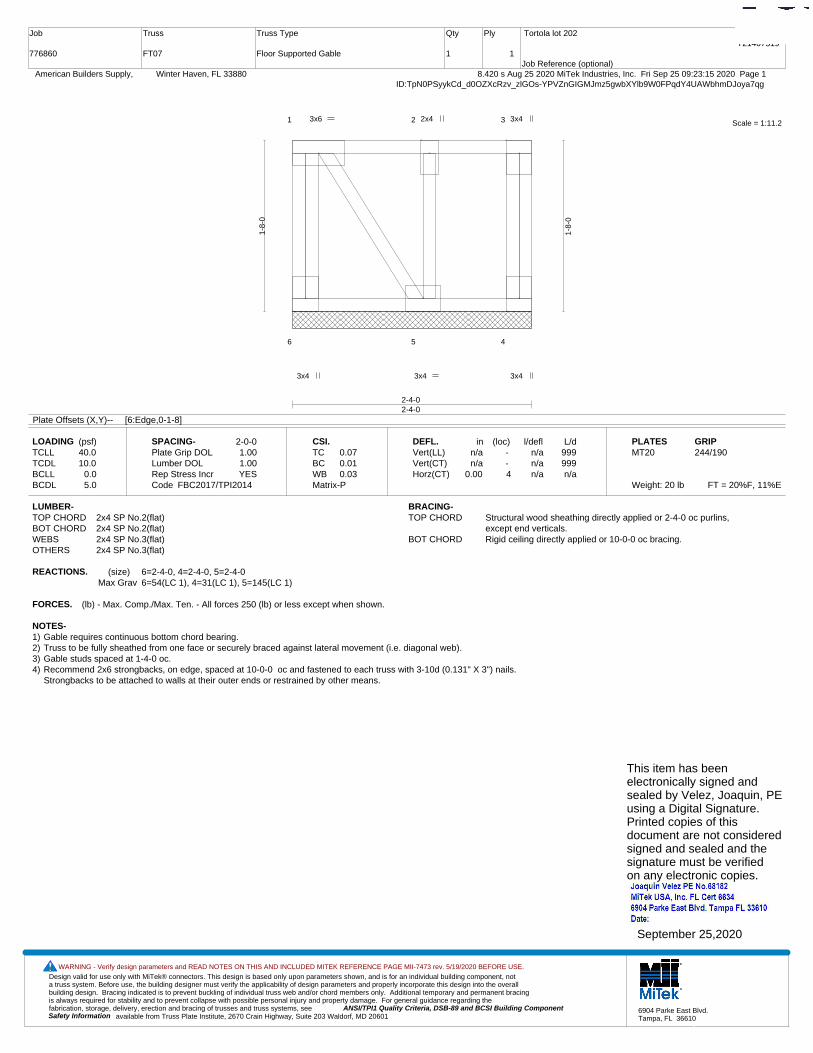
Design valid for use only with MiTek® connectors. This design is based only upon parameters shown, and is for an individual building component, not a truss system. Before use, the building designer must verify the applicability of design parameters and properly incorporate this design into the overall building design. Bracing indicated is to prevent buckling of individual truss web and/or chord members only. Additional temporary and permanent bracing is always required for stability and to prevent collapse with possible personal injury and property damage. For general guidance regarding the fabrication, storage, delivery, erection and bracing of trusses and truss systems, see ANSI/TPI1 Quality Criteria, DSB-89 and BCSI Building Component
available from Truss Plate Institute, 2670 Crain Highway, Suite 203 Waldorf, MD 20601Safety Information
WARNING - Verify design parameters and READ NOTES ON THIS AND INCLUDED MITEK REFERENCE PAGE MII-7473 rev. 5/19/2020 BEFORE USE.
6904 Parke East Blvd.Tampa, FL 36610
Job
776860
Truss
FT07
Truss Type
Floor Supported Gable
Qty
1
Ply
1
Tortola lot 202
Job Reference (optional)
T21407519
8.420 s Aug 25 2020 MiTek Industries, Inc. Fri Sep 25 09:23:15 2020 Page 1 American Builders Supply, Winter Haven, FL 33880ID:TpN0PSyykCd_d0OZXcRzv_zlGOs-YPVZnGIGMJmz5gwbXYlb9W0FPqdY4UAWbhmDJoya7qg
Scale = 1:11.21 2 3
6 5 4
3x4 3x4
3x6 3x4
3x4
2x4
2-4-02-4-0
1-8-
0
1-8-
0
Plate Offsets (X,Y)-- [6:Edge,0-1-8]
LOADING (psf)TCLLTCDLBCLLBCDL
40.010.0
0.05.0
SPACING-Plate Grip DOLLumber DOL Rep Stress IncrCode
2-0-01.001.00YES
FBC2017/TPI2014
CSI.TCBCWBMatrix-P
0.070.010.03
DEFL.Vert(LL)Vert(CT)Horz(CT)
inn/an/a
0.00
(loc) - - 4
l/defln/an/an/a
L/d999999n/a
PLATESMT20
Weight: 20 lb FT = 20%F, 11%E
GRIP244/190
LUMBER-TOP CHORD 2x4 SP No.2(flat)BOT CHORD 2x4 SP No.2(flat)WEBS 2x4 SP No.3(flat)OTHERS 2x4 SP No.3(flat)
BRACING-TOP CHORD Structural wood sheathing directly applied or 2-4-0 oc purlins,
except end verticals.BOT CHORD Rigid ceiling directly applied or 10-0-0 oc bracing.
REACTIONS. (size) 6=2-4-0, 4=2-4-0, 5=2-4-0Max Grav 6=54(LC 1), 4=31(LC 1), 5=145(LC 1)
FORCES. (lb) - Max. Comp./Max. Ten. - All forces 250 (lb) or less except when shown.
NOTES-1) Gable requires continuous bottom chord bearing. 2) Truss to be fully sheathed from one face or securely braced against lateral movement (i.e. diagonal web).3) Gable studs spaced at 1-4-0 oc.4) Recommend 2x6 strongbacks, on edge, spaced at 10-0-0 oc and fastened to each truss with 3-10d (0.131" X 3") nails.
Strongbacks to be attached to walls at their outer ends or restrained by other means.
This item has beenelectronically signed andsealed by Velez, Joaquin, PEusing a Digital Signature.Printed copies of thisdocument are not consideredsigned and sealed and thesignature must be verified on any electronic copies.
September 25,2020
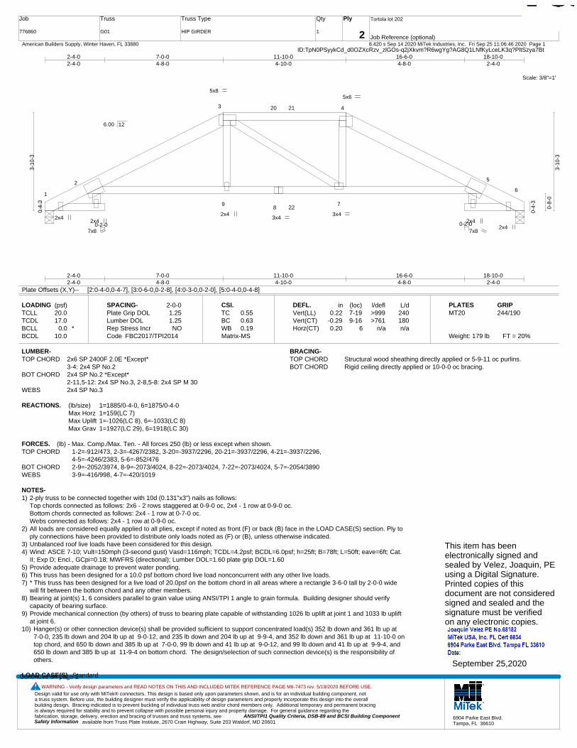
Design valid for use only with MiTek® connectors. This design is based only upon parameters shown, and is for an individual building component, not a truss system. Before use, the building designer must verify the applicability of design parameters and properly incorporate this design into the overall building design. Bracing indicated is to prevent buckling of individual truss web and/or chord members only. Additional temporary and permanent bracing is always required for stability and to prevent collapse with possible personal injury and property damage. For general guidance regarding the fabrication, storage, delivery, erection and bracing of trusses and truss systems, see ANSI/TPI1 Quality Criteria, DSB-89 and BCSI Building Component
available from Truss Plate Institute, 2670 Crain Highway, Suite 203 Waldorf, MD 20601Safety Information
WARNING - Verify design parameters and READ NOTES ON THIS AND INCLUDED MITEK REFERENCE PAGE MII-7473 rev. 5/19/2020 BEFORE USE.
6904 Parke East Blvd.Tampa, FL 36610
Job
776860
Truss
G01
Truss Type
HIP GIRDER
Qty
1
Ply
2
Tortola lot 202
Job Reference (optional)
T21407520
8.420 s Sep 14 2020 MiTek Industries, Inc. Fri Sep 25 11:06:46 2020 Page 1 American Builders Supply, Winter Haven, FL 33880ID:TpN0PSyykCd_d0OZXcRzv_zlGOs-q2jXkvm?R6wgYg?AG8Q1LNfKyLceLK3q?PltSzya7Bt
Scale: 3/8"=1'
1
2
3 4
5
6
98
7
20 21
22
2x4
5x8 5x6
2x4 2x4
7x8
3x4 2x4
2x4 3x4
7x8 0-2-00-2-0
2-4-02-4-0
7-0-04-8-0
11-10-04-10-0
16-6-04-8-0
18-10-02-4-0
2-4-02-4-0
7-0-04-8-0
11-10-04-10-0
16-6-04-8-0
18-10-02-4-0
0-4-
3
3-10
-3
0-4-
3
0-8-
0
3-10
-3
6.00 12
Plate Offsets (X,Y)-- [2:0-4-0,0-4-7], [3:0-6-0,0-2-8], [4:0-3-0,0-2-0], [5:0-4-0,0-4-8]
LOADING (psf)TCLLTCDLBCLLBCDL
20.017.0
0.0 *10.0
SPACING-Plate Grip DOLLumber DOL Rep Stress IncrCode
2-0-01.251.25NO
FBC2017/TPI2014
CSI.TCBCWBMatrix-MS
0.550.630.19
DEFL.Vert(LL)Vert(CT)Horz(CT)
in0.22
-0.290.20
(loc)7-199-16
6
l/defl>999>761
n/a
L/d240180n/a
PLATESMT20
Weight: 179 lb FT = 20%
GRIP244/190
LUMBER-TOP CHORD 2x6 SP 2400F 2.0E *Except*
3-4: 2x4 SP No.2BOT CHORD 2x4 SP No.2 *Except*
2-11,5-12: 2x4 SP No.3, 2-8,5-8: 2x4 SP M 30WEBS 2x4 SP No.3
BRACING-TOP CHORD Structural wood sheathing directly applied or 5-9-11 oc purlins.BOT CHORD Rigid ceiling directly applied or 10-0-0 oc bracing.
REACTIONS. (lb/size) 1=1885/0-4-0, 6=1875/0-4-0Max Horz 1=159(LC 7)Max Uplift 1=-1026(LC 8), 6=-1033(LC 8)Max Grav 1=1927(LC 29), 6=1918(LC 30)
FORCES. (lb) - Max. Comp./Max. Ten. - All forces 250 (lb) or less except when shown.TOP CHORD 1-2=-912/473, 2-3=-4267/2382, 3-20=-3937/2296, 20-21=-3937/2296, 4-21=-3937/2296,
4-5=-4246/2383, 5-6=-852/476BOT CHORD 2-9=-2052/3974, 8-9=-2073/4024, 8-22=-2073/4024, 7-22=-2073/4024, 5-7=-2054/3890WEBS 3-9=-416/998, 4-7=-420/1019
NOTES-1) 2-ply truss to be connected together with 10d (0.131"x3") nails as follows:
Top chords connected as follows: 2x6 - 2 rows staggered at 0-9-0 oc, 2x4 - 1 row at 0-9-0 oc.Bottom chords connected as follows: 2x4 - 1 row at 0-7-0 oc.Webs connected as follows: 2x4 - 1 row at 0-9-0 oc.
2) All loads are considered equally applied to all plies, except if noted as front (F) or back (B) face in the LOAD CASE(S) section. Ply toply connections have been provided to distribute only loads noted as (F) or (B), unless otherwise indicated.
3) Unbalanced roof live loads have been considered for this design.4) Wind: ASCE 7-10; Vult=150mph (3-second gust) Vasd=116mph; TCDL=4.2psf; BCDL=6.0psf; h=25ft; B=78ft; L=50ft; eave=6ft; Cat.
II; Exp D; Encl., GCpi=0.18; MWFRS (directional); Lumber DOL=1.60 plate grip DOL=1.605) Provide adequate drainage to prevent water ponding.6) This truss has been designed for a 10.0 psf bottom chord live load nonconcurrent with any other live loads.7) * This truss has been designed for a live load of 20.0psf on the bottom chord in all areas where a rectangle 3-6-0 tall by 2-0-0 wide
will fit between the bottom chord and any other members.8) Bearing at joint(s) 1, 6 considers parallel to grain value using ANSI/TPI 1 angle to grain formula. Building designer should verify
capacity of bearing surface.9) Provide mechanical connection (by others) of truss to bearing plate capable of withstanding 1026 lb uplift at joint 1 and 1033 lb uplift
at joint 6.10) Hanger(s) or other connection device(s) shall be provided sufficient to support concentrated load(s) 352 lb down and 361 lb up at
7-0-0, 235 lb down and 204 lb up at 9-0-12, and 235 lb down and 204 lb up at 9-9-4, and 352 lb down and 361 lb up at 11-10-0 ontop chord, and 650 lb down and 385 lb up at 7-0-0, 99 lb down and 41 lb up at 9-0-12, and 99 lb down and 41 lb up at 9-9-4, and650 lb down and 385 lb up at 11-9-4 on bottom chord. The design/selection of such connection device(s) is the responsibility ofothers.
LOAD CASE(S) StandardContinued on page 2
This item has beenelectronically signed andsealed by Velez, Joaquin, PEusing a Digital Signature.Printed copies of thisdocument are not consideredsigned and sealed and thesignature must be verified on any electronic copies.
September 25,2020
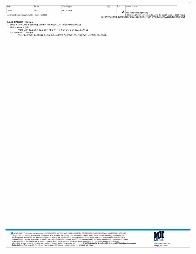
Design valid for use only with MiTek® connectors. This design is based only upon parameters shown, and is for an individual building component, not a truss system. Before use, the building designer must verify the applicability of design parameters and properly incorporate this design into the overall building design. Bracing indicated is to prevent buckling of individual truss web and/or chord members only. Additional temporary and permanent bracing is always required for stability and to prevent collapse with possible personal injury and property damage. For general guidance regarding the fabrication, storage, delivery, erection and bracing of trusses and truss systems, see ANSI/TPI1 Quality Criteria, DSB-89 and BCSI Building Component
available from Truss Plate Institute, 2670 Crain Highway, Suite 203 Waldorf, MD 20601Safety Information
WARNING - Verify design parameters and READ NOTES ON THIS AND INCLUDED MITEK REFERENCE PAGE MII-7473 rev. 5/19/2020 BEFORE USE.
6904 Parke East Blvd.Tampa, FL 36610
Job
776860
Truss
G01
Truss Type
HIP GIRDER
Qty
1
Ply
2
Tortola lot 202
Job Reference (optional)
T21407520
8.420 s Sep 14 2020 MiTek Industries, Inc. Fri Sep 25 11:06:46 2020 Page 2 American Builders Supply, Winter Haven, FL 33880ID:TpN0PSyykCd_d0OZXcRzv_zlGOs-q2jXkvm?R6wgYg?AG8Q1LNfKyLceLK3q?PltSzya7Bt
LOAD CASE(S) Standard1) Dead + Roof Live (balanced): Lumber Increase=1.25, Plate Increase=1.25
Uniform Loads (plf)Vert: 1-2=-96, 2-15=-96, 3-15=-74, 3-4=-74, 4-5=-74, 5-6=-96, 14-17=-20
Concentrated Loads (lb)Vert: 3=-135(B) 4=-135(B) 8=-95(B) 9=-636(B) 7=-636(B) 20=-135(B) 21=-135(B) 22=-95(B)
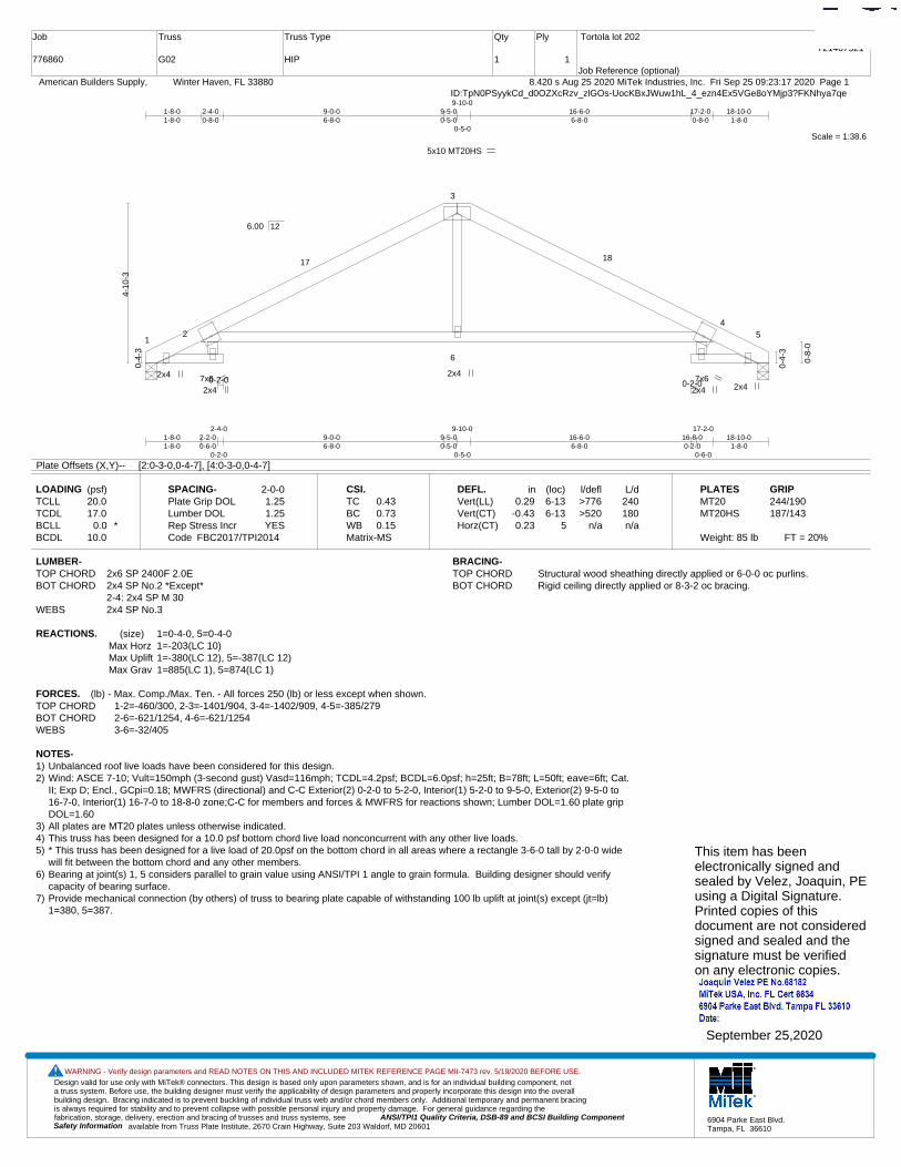
Design valid for use only with MiTek® connectors. This design is based only upon parameters shown, and is for an individual building component, not a truss system. Before use, the building designer must verify the applicability of design parameters and properly incorporate this design into the overall building design. Bracing indicated is to prevent buckling of individual truss web and/or chord members only. Additional temporary and permanent bracing is always required for stability and to prevent collapse with possible personal injury and property damage. For general guidance regarding the fabrication, storage, delivery, erection and bracing of trusses and truss systems, see ANSI/TPI1 Quality Criteria, DSB-89 and BCSI Building Component
available from Truss Plate Institute, 2670 Crain Highway, Suite 203 Waldorf, MD 20601Safety Information
WARNING - Verify design parameters and READ NOTES ON THIS AND INCLUDED MITEK REFERENCE PAGE MII-7473 rev. 5/19/2020 BEFORE USE.
6904 Parke East Blvd.Tampa, FL 36610
Job
776860
Truss
G02
Truss Type
HIP
Qty
1
Ply
1
Tortola lot 202
Job Reference (optional)
T21407521
8.420 s Aug 25 2020 MiTek Industries, Inc. Fri Sep 25 09:23:17 2020 Page 1 American Builders Supply, Winter Haven, FL 33880ID:TpN0PSyykCd_d0OZXcRzv_zlGOs-UocKBxJWuw1hL_4_ezn4Ex5VGe8oYMjp3?FKNhya7qe
Scale = 1:38.6
12
3
4
5
6
17 18
2x4
5x10 MT20HS
2x4 7x6 7x6
2x4
2x4 2x4 0-2-0 0-2-0
1-8-01-8-0
2-2-00-6-0
2-4-0
0-2-0
9-0-06-8-0
9-5-00-5-0
9-10-0
0-5-0
16-6-06-8-0
16-8-00-2-0
17-2-0
0-6-0
18-10-01-8-0
1-8-01-8-0
2-4-00-8-0
9-0-06-8-0
9-5-00-5-0
9-10-0
0-5-0
16-6-06-8-0
17-2-00-8-0
18-10-01-8-0
0-4-
3
4-10
-3
0-4-
3
0-8-
0
6.00 12
Plate Offsets (X,Y)-- [2:0-3-0,0-4-7], [4:0-3-0,0-4-7]
LOADING (psf)TCLLTCDLBCLLBCDL
20.017.0
0.0 *10.0
SPACING-Plate Grip DOLLumber DOL Rep Stress IncrCode
2-0-01.251.25YES
FBC2017/TPI2014
CSI.TCBCWBMatrix-MS
0.430.730.15
DEFL.Vert(LL)Vert(CT)Horz(CT)
in0.29
-0.430.23
(loc)6-136-13
5
l/defl>776>520
n/a
L/d240180n/a
PLATESMT20MT20HS
Weight: 85 lb FT = 20%
GRIP244/190187/143
LUMBER-TOP CHORD 2x6 SP 2400F 2.0EBOT CHORD 2x4 SP No.2 *Except*
2-4: 2x4 SP M 30WEBS 2x4 SP No.3
BRACING-TOP CHORD Structural wood sheathing directly applied or 6-0-0 oc purlins.BOT CHORD Rigid ceiling directly applied or 8-3-2 oc bracing.
REACTIONS. (size) 1=0-4-0, 5=0-4-0Max Horz 1=-203(LC 10)Max Uplift 1=-380(LC 12), 5=-387(LC 12)Max Grav 1=885(LC 1), 5=874(LC 1)
FORCES. (lb) - Max. Comp./Max. Ten. - All forces 250 (lb) or less except when shown.TOP CHORD 1-2=-460/300, 2-3=-1401/904, 3-4=-1402/909, 4-5=-385/279BOT CHORD 2-6=-621/1254, 4-6=-621/1254WEBS 3-6=-32/405
NOTES-1) Unbalanced roof live loads have been considered for this design.2) Wind: ASCE 7-10; Vult=150mph (3-second gust) Vasd=116mph; TCDL=4.2psf; BCDL=6.0psf; h=25ft; B=78ft; L=50ft; eave=6ft; Cat.
II; Exp D; Encl., GCpi=0.18; MWFRS (directional) and C-C Exterior(2) 0-2-0 to 5-2-0, Interior(1) 5-2-0 to 9-5-0, Exterior(2) 9-5-0 to16-7-0, Interior(1) 16-7-0 to 18-8-0 zone;C-C for members and forces & MWFRS for reactions shown; Lumber DOL=1.60 plate gripDOL=1.60
3) All plates are MT20 plates unless otherwise indicated. 4) This truss has been designed for a 10.0 psf bottom chord live load nonconcurrent with any other live loads.5) * This truss has been designed for a live load of 20.0psf on the bottom chord in all areas where a rectangle 3-6-0 tall by 2-0-0 wide
will fit between the bottom chord and any other members.6) Bearing at joint(s) 1, 5 considers parallel to grain value using ANSI/TPI 1 angle to grain formula. Building designer should verify
capacity of bearing surface.7) Provide mechanical connection (by others) of truss to bearing plate capable of withstanding 100 lb uplift at joint(s) except (jt=lb)
1=380, 5=387.
This item has beenelectronically signed andsealed by Velez, Joaquin, PEusing a Digital Signature.Printed copies of thisdocument are not consideredsigned and sealed and thesignature must be verified on any electronic copies.
September 25,2020
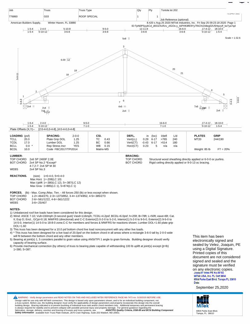
Design valid for use only with MiTek® connectors. This design is based only upon parameters shown, and is for an individual building component, not a truss system. Before use, the building designer must verify the applicability of design parameters and properly incorporate this design into the overall building design. Bracing indicated is to prevent buckling of individual truss web and/or chord members only. Additional temporary and permanent bracing is always required for stability and to prevent collapse with possible personal injury and property damage. For general guidance regarding the fabrication, storage, delivery, erection and bracing of trusses and truss systems, see ANSI/TPI1 Quality Criteria, DSB-89 and BCSI Building Component
available from Truss Plate Institute, 2670 Crain Highway, Suite 203 Waldorf, MD 20601Safety Information
WARNING - Verify design parameters and READ NOTES ON THIS AND INCLUDED MITEK REFERENCE PAGE MII-7473 rev. 5/19/2020 BEFORE USE.
6904 Parke East Blvd.Tampa, FL 36610
Job
776860
Truss
G03
Truss Type
ROOF SPECIAL
Qty
1
Ply
1
Tortola lot 202
Job Reference (optional)
T21407522
8.420 s Aug 25 2020 MiTek Industries, Inc. Fri Sep 25 09:23:18 2020 Page 1 American Builders Supply, Winter Haven, FL 33880ID:TpN0PSyykCd_d0OZXcRzv_zlGOs-y_AiPHK8fE9Yy7fAChIJn8eg02U5HpzyIf_tw7ya7qd
Scale = 1:32.6
1
2
3
4
5
76
18
1920
21
2x4
5x8
2x4 2x4
4x6 7x8 2x4
2x4 7x8 0-2-0
0-2-0
1-5-41-5-4
2-4-00-10-12
9-5-07-1-0
16-6-07-1-0
17-4-120-10-12
18-10-01-5-4
1-5-41-5-4
2-4-00-10-12
5-10-83-6-8
9-5-03-6-8
12-11-83-6-8
16-6-03-6-8
17-4-120-10-12
18-10-01-5-4
0-4-
3
5-0-
11
0-4-
3
0-8-
0
6.00 12
Plate Offsets (X,Y)-- [2:0-4-0,0-4-8], [4:0-4-0,0-4-8]
LOADING (psf)TCLLTCDLBCLLBCDL
20.017.0
0.0 *10.0
SPACING-Plate Grip DOLLumber DOL Rep Stress IncrCode
2-0-01.251.25YES
FBC2017/TPI2014
CSI.TCBCWBMatrix-MS
0.430.660.15
DEFL.Vert(LL)Vert(CT)Horz(CT)
in0.29
-0.430.23
(loc)6-176-17
5
l/defl>765>514
n/a
L/d240180n/a
PLATESMT20
Weight: 85 lb FT = 20%
GRIP244/190
LUMBER-TOP CHORD 2x6 SP 2400F 2.0EBOT CHORD 2x4 SP No.2 *Except*
4-7,2-7: 2x4 SP M 30WEBS 2x4 SP No.3
BRACING-TOP CHORD Structural wood sheathing directly applied or 6-0-0 oc purlins.BOT CHORD Rigid ceiling directly applied or 9-0-13 oc bracing.
REACTIONS. (size) 1=0-4-0, 5=0-4-0Max Horz 1=-208(LC 10)Max Uplift 1=-380(LC 12), 5=-387(LC 12)Max Grav 1=885(LC 1), 5=874(LC 1)
FORCES. (lb) - Max. Comp./Max. Ten. - All forces 250 (lb) or less except when shown.TOP CHORD 1-2=-464/270, 2-3=-1373/852, 3-4=-1374/852, 4-5=-385/273BOT CHORD 2-6=-561/1222, 4-6=-561/1222WEBS 3-6=-25/407
NOTES-1) Unbalanced roof live loads have been considered for this design.2) Wind: ASCE 7-10; Vult=150mph (3-second gust) Vasd=116mph; TCDL=4.2psf; BCDL=6.0psf; h=25ft; B=78ft; L=50ft; eave=6ft; Cat.
II; Exp D; Encl., GCpi=0.18; MWFRS (directional) and C-C Exterior(2) 0-2-0 to 5-2-0, Interior(1) 5-2-0 to 9-5-0, Exterior(2) 9-5-0 to14-5-0, Interior(1) 14-5-0 to 18-8-0 zone;C-C for members and forces & MWFRS for reactions shown; Lumber DOL=1.60 plate gripDOL=1.60
3) This truss has been designed for a 10.0 psf bottom chord live load nonconcurrent with any other live loads.4) * This truss has been designed for a live load of 20.0psf on the bottom chord in all areas where a rectangle 3-6-0 tall by 2-0-0 wide
will fit between the bottom chord and any other members.5) Bearing at joint(s) 1, 5 considers parallel to grain value using ANSI/TPI 1 angle to grain formula. Building designer should verify
capacity of bearing surface.6) Provide mechanical connection (by others) of truss to bearing plate capable of withstanding 100 lb uplift at joint(s) except (jt=lb)
1=380, 5=387.
This item has beenelectronically signed andsealed by Velez, Joaquin, PEusing a Digital Signature.Printed copies of thisdocument are not consideredsigned and sealed and thesignature must be verified on any electronic copies.
September 25,2020

Design valid for use only with MiTek® connectors. This design is based only upon parameters shown, and is for an individual building component, not a truss system. Before use, the building designer must verify the applicability of design parameters and properly incorporate this design into the overall building design. Bracing indicated is to prevent buckling of individual truss web and/or chord members only. Additional temporary and permanent bracing is always required for stability and to prevent collapse with possible personal injury and property damage. For general guidance regarding the fabrication, storage, delivery, erection and bracing of trusses and truss systems, see ANSI/TPI1 Quality Criteria, DSB-89 and BCSI Building Component
available from Truss Plate Institute, 2670 Crain Highway, Suite 203 Waldorf, MD 20601Safety Information
WARNING - Verify design parameters and READ NOTES ON THIS AND INCLUDED MITEK REFERENCE PAGE MII-7473 rev. 5/19/2020 BEFORE USE.
6904 Parke East Blvd.Tampa, FL 36610
Job
776860
Truss
G04
Truss Type
Common
Qty
4
Ply
1
Tortola lot 202
Job Reference (optional)
T21407523
8.420 s Aug 25 2020 MiTek Industries, Inc. Fri Sep 25 09:23:19 2020 Page 1 American Builders Supply, Winter Haven, FL 33880ID:TpN0PSyykCd_d0OZXcRzv_zlGOs-QBk4cdLmQXHPaHEMmOpYKMAn_Smo0D_6WJkRSaya7qc
Scale = 1:32.5
1
2
3
4
5
6
7
1415
1617
4x4
4x4
5x8
2x4 2x4
4x4
9-5-09-5-0
18-10-09-5-0
6-10-76-10-7
9-5-02-6-9
11-11-92-6-9
18-10-06-10-7
19-10-01-0-0
0-4-
3
5-0-
11
0-4-
3
6.00 12
Plate Offsets (X,Y)-- [7:0-4-0,0-3-0]
LOADING (psf)TCLLTCDLBCLLBCDL
20.017.0
0.0 *10.0
SPACING-Plate Grip DOLLumber DOL Rep Stress IncrCode
2-0-01.251.25YES
FBC2017/TPI2014
CSI.TCBCWBMatrix-MS
0.670.950.36
DEFL.Vert(LL)Vert(CT)Horz(CT)
in0.17
-0.340.03
(loc)7-107-10
5
l/defl>999>656
n/a
L/d240180n/a
PLATESMT20
Weight: 80 lb FT = 20%
GRIP244/190
LUMBER-TOP CHORD 2x4 SP No.2BOT CHORD 2x4 SP No.2WEBS 2x4 SP No.3
BRACING-TOP CHORD Structural wood sheathing directly applied or 3-7-13 oc purlins.BOT CHORD Rigid ceiling directly applied or 2-2-0 oc bracing.
REACTIONS. (size) 1=0-4-0, 5=0-4-0Max Horz 1=-229(LC 10)Max Uplift 1=-394(LC 12), 5=-487(LC 12)Max Grav 1=883(LC 1), 5=961(LC 1)
FORCES. (lb) - Max. Comp./Max. Ten. - All forces 250 (lb) or less except when shown.TOP CHORD 1-2=-1392/904, 2-3=-1121/822, 3-4=-1120/794, 4-5=-1389/882BOT CHORD 1-7=-618/1234, 5-7=-634/1185WEBS 3-7=-724/958, 4-7=-506/507, 2-7=-513/512
NOTES-1) Unbalanced roof live loads have been considered for this design.2) Wind: ASCE 7-10; Vult=150mph (3-second gust) Vasd=116mph; TCDL=4.2psf; BCDL=6.0psf; h=25ft; B=78ft; L=50ft; eave=6ft; Cat.
II; Exp D; Encl., GCpi=0.18; MWFRS (directional) and C-C Exterior(2) 0-0-0 to 5-0-0, Interior(1) 5-0-0 to 9-5-0, Exterior(2) 9-5-0 to14-5-0, Interior(1) 14-5-0 to 19-10-0 zone;C-C for members and forces & MWFRS for reactions shown; Lumber DOL=1.60 plate gripDOL=1.60
3) This truss has been designed for a 10.0 psf bottom chord live load nonconcurrent with any other live loads.4) * This truss has been designed for a live load of 20.0psf on the bottom chord in all areas where a rectangle 3-6-0 tall by 2-0-0 wide
will fit between the bottom chord and any other members.5) Provide mechanical connection (by others) of truss to bearing plate capable of withstanding 100 lb uplift at joint(s) except (jt=lb)
1=394, 5=487.This item has beenelectronically signed andsealed by Velez, Joaquin, PEusing a Digital Signature.Printed copies of thisdocument are not consideredsigned and sealed and thesignature must be verified on any electronic copies.
September 25,2020
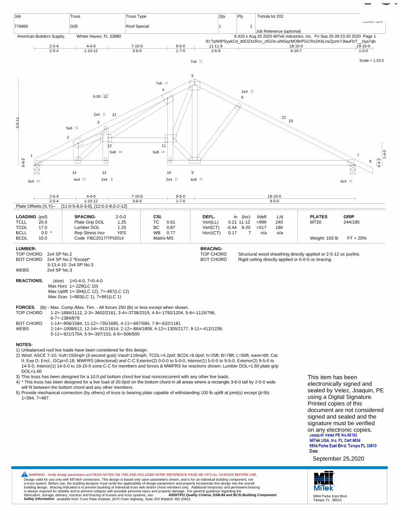
Design valid for use only with MiTek® connectors. This design is based only upon parameters shown, and is for an individual building component, not a truss system. Before use, the building designer must verify the applicability of design parameters and properly incorporate this design into the overall building design. Bracing indicated is to prevent buckling of individual truss web and/or chord members only. Additional temporary and permanent bracing is always required for stability and to prevent collapse with possible personal injury and property damage. For general guidance regarding the fabrication, storage, delivery, erection and bracing of trusses and truss systems, see ANSI/TPI1 Quality Criteria, DSB-89 and BCSI Building Component
available from Truss Plate Institute, 2670 Crain Highway, Suite 203 Waldorf, MD 20601Safety Information
WARNING - Verify design parameters and READ NOTES ON THIS AND INCLUDED MITEK REFERENCE PAGE MII-7473 rev. 5/19/2020 BEFORE USE.
6904 Parke East Blvd.Tampa, FL 36610
Job
776860
Truss
G05
Truss Type
Roof Special
Qty
1
Ply
1
Tortola lot 202
Job Reference (optional)
T21407524
8.420 s Aug 25 2020 MiTek Industries, Inc. Fri Sep 25 09:23:20 2020 Page 1 American Builders Supply, Winter Haven, FL 33880ID:TpN0PSyykCd_d0OZXcRzv_zlGOs-uNISqzMOBrPGCRoZK6LnsZjzmr7JlauFlzT__0ya7qb
Scale = 1:33.0
1
2
3
4
5
6
7
8
14 13
12 11
10 9
2122
23
3x4 2x4
2x4
7x6
2x4 4x4
5x6
4x4
5x8
4x8
5x8
7x6
2x4
2-5-42-5-4
4-4-01-10-12
7-10-03-6-0
9-5-01-7-0
18-10-09-5-0
2-5-42-5-4
4-4-01-10-12
7-10-03-6-0
9-5-01-7-0
11-11-92-6-9
18-10-06-10-7
19-10-01-0-0
0-4-
3
5-0-
11
0-4-
3 1-4-
0
6.00 12
Plate Offsets (X,Y)-- [11:0-5-8,0-3-0], [12:0-2-8,0-2-12]
LOADING (psf)TCLLTCDLBCLLBCDL
20.017.0
0.0 *10.0
SPACING-Plate Grip DOLLumber DOL Rep Stress IncrCode
2-0-01.251.25YES
FBC2017/TPI2014
CSI.TCBCWBMatrix-MS
0.610.870.77
DEFL.Vert(LL)Vert(CT)Horz(CT)
in0.21
-0.440.17
(loc)11-12
9-207
l/defl>999>517
n/a
L/d240180n/a
PLATESMT20
Weight: 103 lb FT = 20%
GRIP244/190
LUMBER-TOP CHORD 2x4 SP No.2BOT CHORD 2x4 SP No.2 *Except*
3-13,4-10: 2x4 SP No.3WEBS 2x4 SP No.3
BRACING-TOP CHORD Structural wood sheathing directly applied or 2-5-12 oc purlins.BOT CHORD Rigid ceiling directly applied or 6-0-0 oc bracing.
REACTIONS. (size) 1=0-4-0, 7=0-4-0Max Horz 1=-229(LC 10)Max Uplift 1=-394(LC 12), 7=-487(LC 12)Max Grav 1=883(LC 1), 7=961(LC 1)
FORCES. (lb) - Max. Comp./Max. Ten. - All forces 250 (lb) or less except when shown.TOP CHORD 1-2=-1684/1112, 2-3=-3602/2161, 3-4=-3738/2315, 4-5=-1792/1204, 5-6=-1115/796,
6-7=-1384/879BOT CHORD 1-14=-906/1584, 11-12=-735/1685, 4-11=-697/584, 7-9=-632/1181WEBS 2-14=-1008/612, 12-14=-912/1614, 2-12=-884/1808, 4-12=-1305/2177, 9-11=-412/1239,
5-11=-921/1704, 5-9=-397/153, 6-9=-506/500
NOTES-1) Unbalanced roof live loads have been considered for this design.2) Wind: ASCE 7-10; Vult=150mph (3-second gust) Vasd=116mph; TCDL=4.2psf; BCDL=6.0psf; h=25ft; B=78ft; L=50ft; eave=6ft; Cat.
II; Exp D; Encl., GCpi=0.18; MWFRS (directional) and C-C Exterior(2) 0-0-0 to 5-0-0, Interior(1) 5-0-0 to 9-5-0, Exterior(2) 9-5-0 to14-5-0, Interior(1) 14-5-0 to 19-10-0 zone;C-C for members and forces & MWFRS for reactions shown; Lumber DOL=1.60 plate gripDOL=1.60
3) This truss has been designed for a 10.0 psf bottom chord live load nonconcurrent with any other live loads.4) * This truss has been designed for a live load of 20.0psf on the bottom chord in all areas where a rectangle 3-6-0 tall by 2-0-0 wide
will fit between the bottom chord and any other members.5) Provide mechanical connection (by others) of truss to bearing plate capable of withstanding 100 lb uplift at joint(s) except (jt=lb)
1=394, 7=487.
This item has beenelectronically signed andsealed by Velez, Joaquin, PEusing a Digital Signature.Printed copies of thisdocument are not consideredsigned and sealed and thesignature must be verified on any electronic copies.
September 25,2020
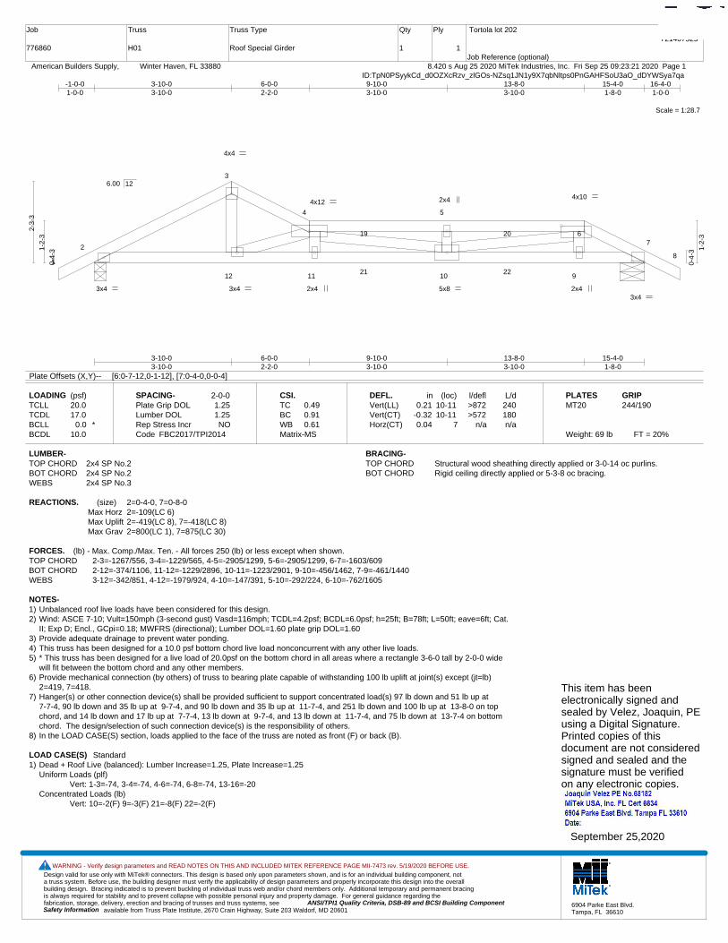
Design valid for use only with MiTek® connectors. This design is based only upon parameters shown, and is for an individual building component, not a truss system. Before use, the building designer must verify the applicability of design parameters and properly incorporate this design into the overall building design. Bracing indicated is to prevent buckling of individual truss web and/or chord members only. Additional temporary and permanent bracing is always required for stability and to prevent collapse with possible personal injury and property damage. For general guidance regarding the fabrication, storage, delivery, erection and bracing of trusses and truss systems, see ANSI/TPI1 Quality Criteria, DSB-89 and BCSI Building Component
available from Truss Plate Institute, 2670 Crain Highway, Suite 203 Waldorf, MD 20601Safety Information
WARNING - Verify design parameters and READ NOTES ON THIS AND INCLUDED MITEK REFERENCE PAGE MII-7473 rev. 5/19/2020 BEFORE USE.
6904 Parke East Blvd.Tampa, FL 36610
Job
776860
Truss
H01
Truss Type
Roof Special Girder
Qty
1
Ply
1
Tortola lot 202
Job Reference (optional)
T21407525
8.420 s Aug 25 2020 MiTek Industries, Inc. Fri Sep 25 09:23:21 2020 Page 1 American Builders Supply, Winter Haven, FL 33880ID:TpN0PSyykCd_d0OZXcRzv_zlGOs-NZsq1JN1y9X7qbNltps0PnGAHFSoU3aO_dDYWSya7qa
Scale = 1:28.7
1
2
3
4 5
67
8
12 11 10 9
19 20
21 22
4x4
4x12 4x10
3x4 3x4
3x4 2x4 5x8
2x4
2x4
3-10-03-10-0
6-0-02-2-0
9-10-03-10-0
13-8-03-10-0
15-4-01-8-0
-1-0-01-0-0
3-10-03-10-0
6-0-02-2-0
9-10-03-10-0
13-8-03-10-0
15-4-01-8-0
16-4-01-0-0
0-4-
31-2-
3
2-3-
3
0-4-
3 1-2-
3
6.00 12
Plate Offsets (X,Y)-- [6:0-7-12,0-1-12], [7:0-4-0,0-0-4]
LOADING (psf)TCLLTCDLBCLLBCDL
20.017.0
0.0 *10.0
SPACING-Plate Grip DOLLumber DOL Rep Stress IncrCode
2-0-01.251.25NO
FBC2017/TPI2014
CSI.TCBCWBMatrix-MS
0.490.910.61
DEFL.Vert(LL)Vert(CT)Horz(CT)
in0.21
-0.320.04
(loc)10-1110-11
7
l/defl>872>572
n/a
L/d240180n/a
PLATESMT20
Weight: 69 lb FT = 20%
GRIP244/190
LUMBER-TOP CHORD 2x4 SP No.2BOT CHORD 2x4 SP No.2WEBS 2x4 SP No.3
BRACING-TOP CHORD Structural wood sheathing directly applied or 3-0-14 oc purlins.BOT CHORD Rigid ceiling directly applied or 5-3-8 oc bracing.
REACTIONS. (size) 2=0-4-0, 7=0-8-0Max Horz 2=-109(LC 6)Max Uplift 2=-419(LC 8), 7=-418(LC 8)Max Grav 2=800(LC 1), 7=875(LC 30)
FORCES. (lb) - Max. Comp./Max. Ten. - All forces 250 (lb) or less except when shown.TOP CHORD 2-3=-1267/556, 3-4=-1229/565, 4-5=-2905/1299, 5-6=-2905/1299, 6-7=-1603/609BOT CHORD 2-12=-374/1106, 11-12=-1229/2896, 10-11=-1223/2901, 9-10=-456/1462, 7-9=-461/1440WEBS 3-12=-342/851, 4-12=-1979/924, 4-10=-147/391, 5-10=-292/224, 6-10=-762/1605
NOTES-1) Unbalanced roof live loads have been considered for this design.2) Wind: ASCE 7-10; Vult=150mph (3-second gust) Vasd=116mph; TCDL=4.2psf; BCDL=6.0psf; h=25ft; B=78ft; L=50ft; eave=6ft; Cat.
II; Exp D; Encl., GCpi=0.18; MWFRS (directional); Lumber DOL=1.60 plate grip DOL=1.603) Provide adequate drainage to prevent water ponding.4) This truss has been designed for a 10.0 psf bottom chord live load nonconcurrent with any other live loads.5) * This truss has been designed for a live load of 20.0psf on the bottom chord in all areas where a rectangle 3-6-0 tall by 2-0-0 wide
will fit between the bottom chord and any other members.6) Provide mechanical connection (by others) of truss to bearing plate capable of withstanding 100 lb uplift at joint(s) except (jt=lb)
2=419, 7=418.7) Hanger(s) or other connection device(s) shall be provided sufficient to support concentrated load(s) 97 lb down and 51 lb up at
7-7-4, 90 lb down and 35 lb up at 9-7-4, and 90 lb down and 35 lb up at 11-7-4, and 251 lb down and 100 lb up at 13-8-0 on topchord, and 14 lb down and 17 lb up at 7-7-4, 13 lb down at 9-7-4, and 13 lb down at 11-7-4, and 75 lb down at 13-7-4 on bottomchord. The design/selection of such connection device(s) is the responsibility of others.
8) In the LOAD CASE(S) section, loads applied to the face of the truss are noted as front (F) or back (B).
LOAD CASE(S) Standard1) Dead + Roof Live (balanced): Lumber Increase=1.25, Plate Increase=1.25
Uniform Loads (plf)Vert: 1-3=-74, 3-4=-74, 4-6=-74, 6-8=-74, 13-16=-20
Concentrated Loads (lb)Vert: 10=-2(F) 9=-3(F) 21=-8(F) 22=-2(F)
This item has beenelectronically signed andsealed by Velez, Joaquin, PEusing a Digital Signature.Printed copies of thisdocument are not consideredsigned and sealed and thesignature must be verified on any electronic copies.
September 25,2020

Design valid for use only with MiTek® connectors. This design is based only upon parameters shown, and is for an individual building component, not a truss system. Before use, the building designer must verify the applicability of design parameters and properly incorporate this design into the overall building design. Bracing indicated is to prevent buckling of individual truss web and/or chord members only. Additional temporary and permanent bracing is always required for stability and to prevent collapse with possible personal injury and property damage. For general guidance regarding the fabrication, storage, delivery, erection and bracing of trusses and truss systems, see ANSI/TPI1 Quality Criteria, DSB-89 and BCSI Building Component
available from Truss Plate Institute, 2670 Crain Highway, Suite 203 Waldorf, MD 20601Safety Information
WARNING - Verify design parameters and READ NOTES ON THIS AND INCLUDED MITEK REFERENCE PAGE MII-7473 rev. 5/19/2020 BEFORE USE.
6904 Parke East Blvd.Tampa, FL 36610
Job
776860
Truss
H02
Truss Type
Hip
Qty
1
Ply
1
Tortola lot 202
Job Reference (optional)
T21407526
8.420 s Aug 25 2020 MiTek Industries, Inc. Fri Sep 25 09:23:22 2020 Page 1 American Builders Supply, Winter Haven, FL 33880ID:TpN0PSyykCd_d0OZXcRzv_zlGOs-rmQDFfNfiSf_RlyxRWNFx_oJffscDYYYCHy53uya7qZ
Scale = 1:28.7
1
2
3 4 5
6
7
8
9
17 1615
1413
12
1110
24 25
4x8 4x6
3x4 2x4
4x6
3x4
4x4 3x4
4x4
4x8 7x8
3x10 MT20HS
3x8
0-2-0 0-2-0
3-8-03-8-0
6-0-02-4-0
11-8-05-8-0
12-8-01-0-0
15-4-02-8-0
-1-0-01-0-0
3-8-03-8-0
6-0-02-4-0
11-8-05-8-0
12-8-01-0-0
15-4-02-8-0
16-4-01-0-0
0-4-
3
2-2-
3
0-4-
3
0-8-
0
2-2-
3
6.00 12
Plate Offsets (X,Y)-- [3:0-5-4,0-2-0], [14:0-6-4,0-2-4]
LOADING (psf)TCLLTCDLBCLLBCDL
20.017.0
0.0 *10.0
SPACING-Plate Grip DOLLumber DOL Rep Stress IncrCode
2-0-01.251.25YES
FBC2017/TPI2014
CSI.TCBCWBMatrix-MS
0.580.680.50
DEFL.Vert(LL)Vert(CT)Horz(CT)
in0.12
-0.220.09
(loc)15
13-148
l/defl>999>854
n/a
L/d240180n/a
PLATESMT20MT20HS
Weight: 77 lb FT = 20%
GRIP244/190187/143
LUMBER-TOP CHORD 2x4 SP No.2BOT CHORD 2x4 SP No.2 *Except*
4-16: 2x4 SP No.3WEBS 2x4 SP No.3
BRACING-TOP CHORD Structural wood sheathing directly applied or 3-5-6 oc purlins.BOT CHORD Rigid ceiling directly applied or 4-10-7 oc bracing. Except:
10-0-0 oc bracing: 14-16, 10-12
REACTIONS. (size) 2=0-4-0, 8=0-8-0Max Horz 2=106(LC 11)Max Uplift 2=-407(LC 12), 8=-405(LC 12)Max Grav 2=800(LC 1), 8=802(LC 1)
FORCES. (lb) - Max. Comp./Max. Ten. - All forces 250 (lb) or less except when shown.TOP CHORD 2-3=-1256/886, 3-4=-2084/1512, 4-5=-1755/1224, 5-6=-1981/1303, 6-7=-2099/1434,
7-8=-1313/945BOT CHORD 2-17=-638/1074, 16-17=-215/250, 4-14=-242/279, 13-14=-1478/2311, 12-13=-1346/2152,
10-12=-265/440, 6-12=-236/291, 8-10=-717/1108WEBS 14-17=-437/868, 3-14=-778/1194, 4-13=-644/480, 5-13=-214/549, 6-13=-396/347,
7-12=-820/1315, 7-10=-684/467
NOTES-1) Unbalanced roof live loads have been considered for this design.2) Wind: ASCE 7-10; Vult=150mph (3-second gust) Vasd=116mph; TCDL=4.2psf; BCDL=6.0psf; h=25ft; B=78ft; L=50ft; eave=6ft; Cat.
II; Exp D; Encl., GCpi=0.18; MWFRS (directional) and C-C Exterior(2) -1-0-0 to 10-8-14, Interior(1) 10-8-14 to 11-8-0, Exterior(2)11-8-0 to 16-4-0 zone;C-C for members and forces & MWFRS for reactions shown; Lumber DOL=1.60 plate grip DOL=1.60
3) Provide adequate drainage to prevent water ponding.4) All plates are MT20 plates unless otherwise indicated. 5) This truss has been designed for a 10.0 psf bottom chord live load nonconcurrent with any other live loads.6) * This truss has been designed for a live load of 20.0psf on the bottom chord in all areas where a rectangle 3-6-0 tall by 2-0-0 wide
will fit between the bottom chord and any other members.7) Provide mechanical connection (by others) of truss to bearing plate capable of withstanding 100 lb uplift at joint(s) except (jt=lb)
2=407, 8=405.
This item has beenelectronically signed andsealed by Velez, Joaquin, PEusing a Digital Signature.Printed copies of thisdocument are not consideredsigned and sealed and thesignature must be verified on any electronic copies.
September 25,2020
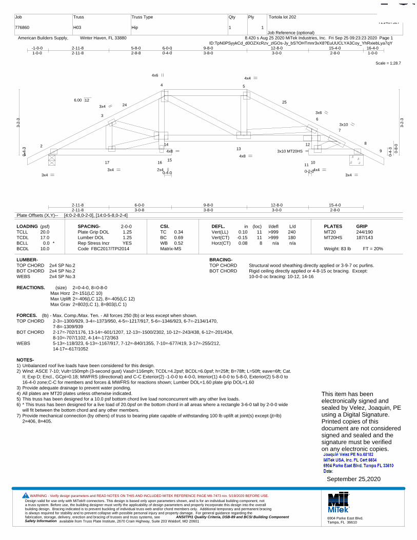
Design valid for use only with MiTek® connectors. This design is based only upon parameters shown, and is for an individual building component, not a truss system. Before use, the building designer must verify the applicability of design parameters and properly incorporate this design into the overall building design. Bracing indicated is to prevent buckling of individual truss web and/or chord members only. Additional temporary and permanent bracing is always required for stability and to prevent collapse with possible personal injury and property damage. For general guidance regarding the fabrication, storage, delivery, erection and bracing of trusses and truss systems, see ANSI/TPI1 Quality Criteria, DSB-89 and BCSI Building Component
available from Truss Plate Institute, 2670 Crain Highway, Suite 203 Waldorf, MD 20601Safety Information
WARNING - Verify design parameters and READ NOTES ON THIS AND INCLUDED MITEK REFERENCE PAGE MII-7473 rev. 5/19/2020 BEFORE USE.
6904 Parke East Blvd.Tampa, FL 36610
Job
776860
Truss
H03
Truss Type
Hip
Qty
1
Ply
1
Tortola lot 202
Job Reference (optional)
T21407527
8.420 s Aug 25 2020 MiTek Industries, Inc. Fri Sep 25 09:23:23 2020 Page 1 American Builders Supply, Winter Haven, FL 33880ID:TpN0PSyykCd_d0OZXcRzv_zlGOs-Jy_bS?OHTmnr3vX8?EuUUCLYA3Coy_YhRxiebLya7qY
Scale = 1:28.7
1
2
3
4 5
6
7
8
9
17 1615
1413
12
1110
2425
4x4
3x4
3x6
4x4 3x4
4x8
4x6
2x4
3x10 MT20HS
3x10
3x4
3x4
4x8
0-2-00-4-0
2-11-82-11-8
6-0-03-0-8
9-8-03-8-0
12-8-03-0-0
15-4-02-8-0
-1-0-01-0-0
2-11-82-11-8
5-8-02-8-8
6-0-00-4-0
9-8-03-8-0
12-8-03-0-0
15-4-02-8-0
16-4-01-0-0
0-4-
3
3-2-
3
0-4-
3
0-8-
0
3-2-
3
6.00 12
Plate Offsets (X,Y)-- [4:0-2-8,0-2-0], [14:0-5-8,0-2-4]
LOADING (psf)TCLLTCDLBCLLBCDL
20.017.0
0.0 *10.0
SPACING-Plate Grip DOLLumber DOL Rep Stress IncrCode
2-0-01.251.25YES
FBC2017/TPI2014
CSI.TCBCWBMatrix-MS
0.340.690.52
DEFL.Vert(LL)Vert(CT)Horz(CT)
in0.10
-0.150.08
(loc)1111
8
l/defl>999>999
n/a
L/d240180n/a
PLATESMT20MT20HS
Weight: 83 lb FT = 20%
GRIP244/190187/143
LUMBER-TOP CHORD 2x4 SP No.2BOT CHORD 2x4 SP No.2WEBS 2x4 SP No.3
BRACING-TOP CHORD Structural wood sheathing directly applied or 3-9-7 oc purlins.BOT CHORD Rigid ceiling directly applied or 4-8-15 oc bracing. Except:
10-0-0 oc bracing: 10-12, 14-16
REACTIONS. (size) 2=0-4-0, 8=0-8-0Max Horz 2=-151(LC 10)Max Uplift 2=-406(LC 12), 8=-405(LC 12)Max Grav 2=802(LC 1), 8=803(LC 1)
FORCES. (lb) - Max. Comp./Max. Ten. - All forces 250 (lb) or less except when shown.TOP CHORD 2-3=-1300/929, 3-4=-1373/950, 4-5=-1217/917, 5-6=-1346/923, 6-7=-2134/1470,
7-8=-1309/939BOT CHORD 2-17=-702/1176, 13-14=-601/1207, 12-13=-1500/2302, 10-12=-243/438, 6-12=-201/434,
8-10=-707/1102, 4-14=-172/363WEBS 5-13=-118/323, 6-13=-1167/917, 7-12=-840/1355, 7-10=-677/419, 3-17=-255/212,
14-17=-617/1052
NOTES-1) Unbalanced roof live loads have been considered for this design.2) Wind: ASCE 7-10; Vult=150mph (3-second gust) Vasd=116mph; TCDL=4.2psf; BCDL=6.0psf; h=25ft; B=78ft; L=50ft; eave=6ft; Cat.
II; Exp D; Encl., GCpi=0.18; MWFRS (directional) and C-C Exterior(2) -1-0-0 to 4-0-0, Interior(1) 4-0-0 to 5-8-0, Exterior(2) 5-8-0 to16-4-0 zone;C-C for members and forces & MWFRS for reactions shown; Lumber DOL=1.60 plate grip DOL=1.60
3) Provide adequate drainage to prevent water ponding.4) All plates are MT20 plates unless otherwise indicated. 5) This truss has been designed for a 10.0 psf bottom chord live load nonconcurrent with any other live loads.6) * This truss has been designed for a live load of 20.0psf on the bottom chord in all areas where a rectangle 3-6-0 tall by 2-0-0 wide
will fit between the bottom chord and any other members.7) Provide mechanical connection (by others) of truss to bearing plate capable of withstanding 100 lb uplift at joint(s) except (jt=lb)
2=406, 8=405.
This item has beenelectronically signed andsealed by Velez, Joaquin, PEusing a Digital Signature.Printed copies of thisdocument are not consideredsigned and sealed and thesignature must be verified on any electronic copies.
September 25,2020
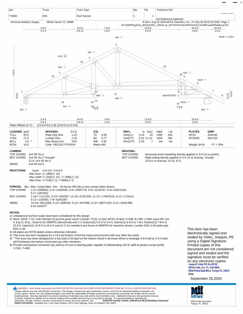
Design valid for use only with MiTek® connectors. This design is based only upon parameters shown, and is for an individual building component, not a truss system. Before use, the building designer must verify the applicability of design parameters and properly incorporate this design into the overall building design. Bracing indicated is to prevent buckling of individual truss web and/or chord members only. Additional temporary and permanent bracing is always required for stability and to prevent collapse with possible personal injury and property damage. For general guidance regarding the fabrication, storage, delivery, erection and bracing of trusses and truss systems, see ANSI/TPI1 Quality Criteria, DSB-89 and BCSI Building Component
available from Truss Plate Institute, 2670 Crain Highway, Suite 203 Waldorf, MD 20601Safety Information
WARNING - Verify design parameters and READ NOTES ON THIS AND INCLUDED MITEK REFERENCE PAGE MII-7473 rev. 5/19/2020 BEFORE USE.
6904 Parke East Blvd.Tampa, FL 36610
Job
776860
Truss
H04
Truss Type
Roof Special
Qty
3
Ply
1
Tortola lot 202
Job Reference (optional)
T21407528
8.420 s Aug 25 2020 MiTek Industries, Inc. Fri Sep 25 09:23:23 2020 Page 1 American Builders Supply, Winter Haven, FL 33880ID:TpN0PSyykCd_d0OZXcRzv_zlGOs-Jy_bS?OHTmnr3vX8?EuUUCLVw3BYyuQhRxiebLya7qY
Scale = 1:28.0
1
2
3
4
5
6
7
8
16 1514
1312
11
109
23
24
25
26
3x4
4x6
2x4
3x4
5x6
3x6
3x4
3x4
3x4
4x8 4x8
3x8 MT20HS
3x10
0-2-00-2-0
3-3-43-3-4
6-0-02-8-12
7-8-01-8-0
12-8-05-0-0
15-4-02-8-0
3-3-43-3-4
6-0-02-8-12
7-8-01-8-0
12-8-05-0-0
15-4-02-8-0
16-4-01-0-0
0-4-
3
4-2-
3
0-4-
3
0-8-
0
6.00 12
Plate Offsets (X,Y)-- [11:0-3-0,0-1-8], [13:0-5-12,0-2-0]
LOADING (psf)TCLLTCDLBCLLBCDL
20.017.0
0.0 *10.0
SPACING-Plate Grip DOLLumber DOL Rep Stress IncrCode
2-0-01.251.25YES
FBC2017/TPI2014
CSI.TCBCWBMatrix-MS
0.550.770.91
DEFL.Vert(LL)Vert(CT)Horz(CT)
in0.14
-0.220.10
(loc)10
11-127
l/defl>999>834
n/a
L/d240180n/a
PLATESMT20MT20HS
Weight: 84 lb FT = 20%
GRIP244/190187/143
LUMBER-TOP CHORD 2x4 SP No.2BOT CHORD 2x4 SP No.2 *Except*
3-15: 2x4 SP No.3WEBS 2x4 SP No.3
BRACING-TOP CHORD Structural wood sheathing directly applied or 3-9-14 oc purlins.BOT CHORD Rigid ceiling directly applied or 4-4-12 oc bracing. Except:
10-0-0 oc bracing: 13-15, 9-11
REACTIONS. (size) 1=0-4-0, 7=0-8-0Max Horz 1=-189(LC 10)Max Uplift 1=-316(LC 12), 7=-409(LC 12)Max Grav 1=723(LC 1), 7=805(LC 1)
FORCES. (lb) - Max. Comp./Max. Ten. - All forces 250 (lb) or less except when shown.TOP CHORD 1-2=-1299/922, 2-3=-1332/926, 3-4=-1050/778, 4-5=-1113/707, 5-6=-2181/1420,
6-7=-1297/822BOT CHORD 1-16=-711/1201, 3-13=-205/307, 12-13=-575/1200, 11-12=-1706/2516, 9-11=-173/414,
5-11=-120/463, 7-9=-628/1087WEBS 13-16=-651/1065, 3-12=-408/329, 4-12=-347/596, 5-12=-1667/1320, 6-11=-829/1389,
6-9=-624/277
NOTES-1) Unbalanced roof live loads have been considered for this design.2) Wind: ASCE 7-10; Vult=150mph (3-second gust) Vasd=116mph; TCDL=4.2psf; BCDL=6.0psf; h=25ft; B=78ft; L=50ft; eave=6ft; Cat.
II; Exp D; Encl., GCpi=0.18; MWFRS (directional) and C-C Exterior(2) 0-0-0 to 5-0-0, Interior(1) 5-0-0 to 7-8-0, Exterior(2) 7-8-0 to12-8-0, Interior(1) 12-8-0 to 16-4-0 zone;C-C for members and forces & MWFRS for reactions shown; Lumber DOL=1.60 plate gripDOL=1.60
3) All plates are MT20 plates unless otherwise indicated. 4) This truss has been designed for a 10.0 psf bottom chord live load nonconcurrent with any other live loads.5) * This truss has been designed for a live load of 20.0psf on the bottom chord in all areas where a rectangle 3-6-0 tall by 2-0-0 wide
will fit between the bottom chord and any other members.6) Provide mechanical connection (by others) of truss to bearing plate capable of withstanding 100 lb uplift at joint(s) except (jt=lb)
1=316, 7=409.
This item has beenelectronically signed andsealed by Velez, Joaquin, PEusing a Digital Signature.Printed copies of thisdocument are not consideredsigned and sealed and thesignature must be verified on any electronic copies.
September 25,2020
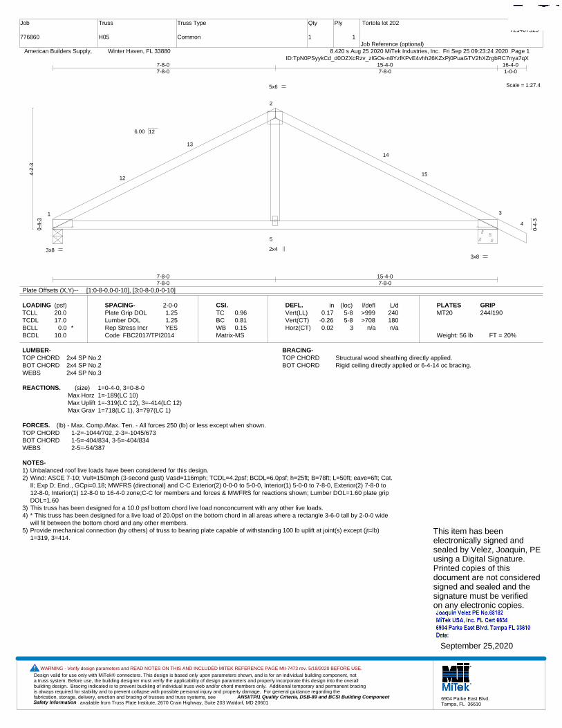
Design valid for use only with MiTek® connectors. This design is based only upon parameters shown, and is for an individual building component, not a truss system. Before use, the building designer must verify the applicability of design parameters and properly incorporate this design into the overall building design. Bracing indicated is to prevent buckling of individual truss web and/or chord members only. Additional temporary and permanent bracing is always required for stability and to prevent collapse with possible personal injury and property damage. For general guidance regarding the fabrication, storage, delivery, erection and bracing of trusses and truss systems, see ANSI/TPI1 Quality Criteria, DSB-89 and BCSI Building Component
available from Truss Plate Institute, 2670 Crain Highway, Suite 203 Waldorf, MD 20601Safety Information
WARNING - Verify design parameters and READ NOTES ON THIS AND INCLUDED MITEK REFERENCE PAGE MII-7473 rev. 5/19/2020 BEFORE USE.
6904 Parke East Blvd.Tampa, FL 36610
Job
776860
Truss
H05
Truss Type
Common
Qty
1
Ply
1
Tortola lot 202
Job Reference (optional)
T21407529
8.420 s Aug 25 2020 MiTek Industries, Inc. Fri Sep 25 09:23:24 2020 Page 1 American Builders Supply, Winter Haven, FL 33880ID:TpN0PSyykCd_d0OZXcRzv_zlGOs-n8YzfKPvE4vhh26KZxPj0PuaGTV2hXZrgbRC7nya7qX
Scale = 1:27.4
1
2
3
4
5
12
13
14
15
3x8 3x8
2x4
5x6
7-8-07-8-0
15-4-07-8-0
7-8-07-8-0
15-4-07-8-0
16-4-01-0-0
0-4-
3
4-2-
3
0-4-
3
6.00 12
Plate Offsets (X,Y)-- [1:0-8-0,0-0-10], [3:0-8-0,0-0-10]
LOADING (psf)TCLLTCDLBCLLBCDL
20.017.0
0.0 *10.0
SPACING-Plate Grip DOLLumber DOL Rep Stress IncrCode
2-0-01.251.25YES
FBC2017/TPI2014
CSI.TCBCWBMatrix-MS
0.960.810.15
DEFL.Vert(LL)Vert(CT)Horz(CT)
in0.17
-0.260.02
(loc)5-85-8
3
l/defl>999>708
n/a
L/d240180n/a
PLATESMT20
Weight: 56 lb FT = 20%
GRIP244/190
LUMBER-TOP CHORD 2x4 SP No.2BOT CHORD 2x4 SP No.2WEBS 2x4 SP No.3
BRACING-TOP CHORD Structural wood sheathing directly applied.BOT CHORD Rigid ceiling directly applied or 6-4-14 oc bracing.
REACTIONS. (size) 1=0-4-0, 3=0-8-0Max Horz 1=-189(LC 10)Max Uplift 1=-319(LC 12), 3=-414(LC 12)Max Grav 1=718(LC 1), 3=797(LC 1)
FORCES. (lb) - Max. Comp./Max. Ten. - All forces 250 (lb) or less except when shown.TOP CHORD 1-2=-1044/702, 2-3=-1045/673BOT CHORD 1-5=-404/834, 3-5=-404/834WEBS 2-5=-54/387
NOTES-1) Unbalanced roof live loads have been considered for this design.2) Wind: ASCE 7-10; Vult=150mph (3-second gust) Vasd=116mph; TCDL=4.2psf; BCDL=6.0psf; h=25ft; B=78ft; L=50ft; eave=6ft; Cat.
II; Exp D; Encl., GCpi=0.18; MWFRS (directional) and C-C Exterior(2) 0-0-0 to 5-0-0, Interior(1) 5-0-0 to 7-8-0, Exterior(2) 7-8-0 to12-8-0, Interior(1) 12-8-0 to 16-4-0 zone;C-C for members and forces & MWFRS for reactions shown; Lumber DOL=1.60 plate gripDOL=1.60
3) This truss has been designed for a 10.0 psf bottom chord live load nonconcurrent with any other live loads.4) * This truss has been designed for a live load of 20.0psf on the bottom chord in all areas where a rectangle 3-6-0 tall by 2-0-0 wide
will fit between the bottom chord and any other members.5) Provide mechanical connection (by others) of truss to bearing plate capable of withstanding 100 lb uplift at joint(s) except (jt=lb)
1=319, 3=414.This item has beenelectronically signed andsealed by Velez, Joaquin, PEusing a Digital Signature.Printed copies of thisdocument are not consideredsigned and sealed and thesignature must be verified on any electronic copies.
September 25,2020
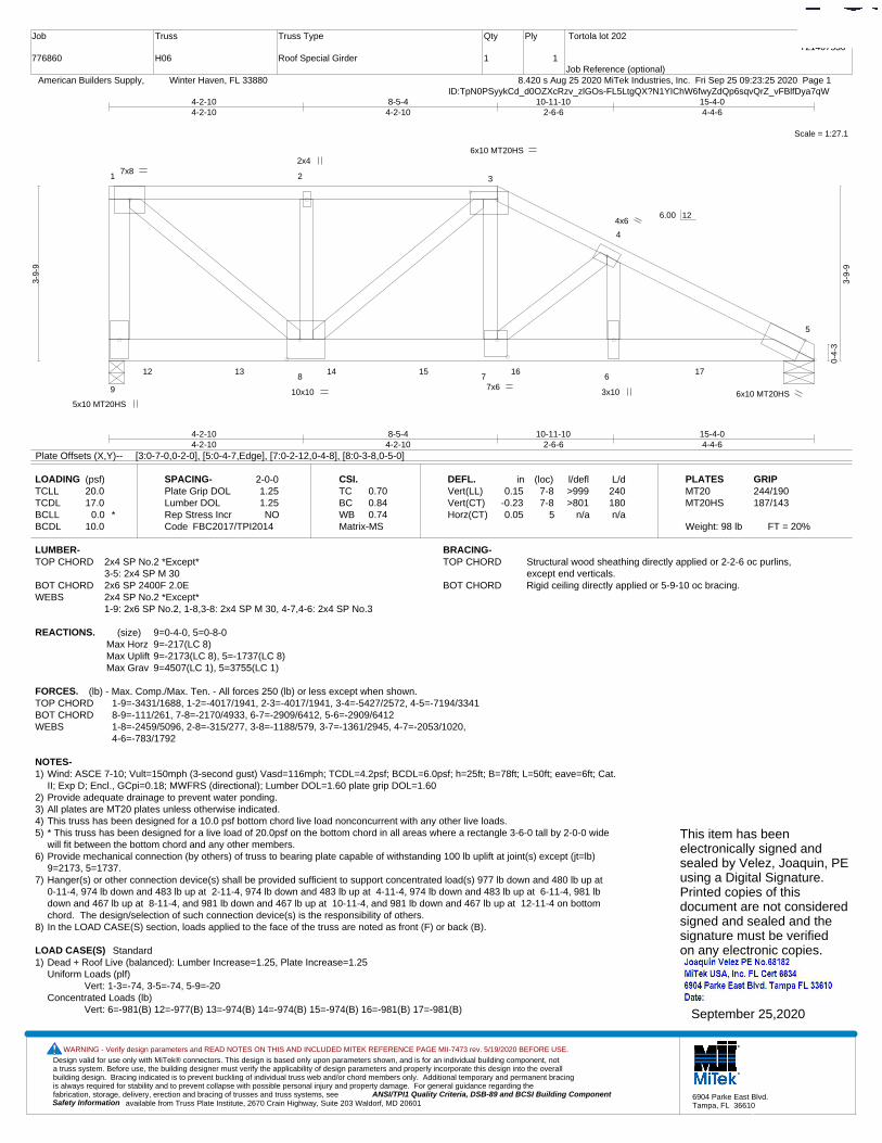
Design valid for use only with MiTek® connectors. This design is based only upon parameters shown, and is for an individual building component, not a truss system. Before use, the building designer must verify the applicability of design parameters and properly incorporate this design into the overall building design. Bracing indicated is to prevent buckling of individual truss web and/or chord members only. Additional temporary and permanent bracing is always required for stability and to prevent collapse with possible personal injury and property damage. For general guidance regarding the fabrication, storage, delivery, erection and bracing of trusses and truss systems, see ANSI/TPI1 Quality Criteria, DSB-89 and BCSI Building Component
available from Truss Plate Institute, 2670 Crain Highway, Suite 203 Waldorf, MD 20601Safety Information
WARNING - Verify design parameters and READ NOTES ON THIS AND INCLUDED MITEK REFERENCE PAGE MII-7473 rev. 5/19/2020 BEFORE USE.
6904 Parke East Blvd.Tampa, FL 36610
Job
776860
Truss
H06
Truss Type
Roof Special Girder
Qty
1
Ply
1
Tortola lot 202
Job Reference (optional)
T21407530
8.420 s Aug 25 2020 MiTek Industries, Inc. Fri Sep 25 09:23:25 2020 Page 1 American Builders Supply, Winter Haven, FL 33880ID:TpN0PSyykCd_d0OZXcRzv_zlGOs-FL5LtgQX?N1YIChW6fwyZdQp6sqvQrZ_vFBlfDya7qW
Scale = 1:27.1
1 2 3
4
5
9
8 7 612 13 14 15 16 17
5x10 MT20HS
7x8
6x10 MT20HS
6x10 MT20HS10x10
2x4
7x6
4x6
3x10
4-2-104-2-10
8-5-44-2-10
10-11-102-6-6
15-4-04-4-6
4-2-104-2-10
8-5-44-2-10
10-11-102-6-6
15-4-04-4-6
3-9-
9
0-4-
3
3-9-
9
6.00 12
Plate Offsets (X,Y)-- [3:0-7-0,0-2-0], [5:0-4-7,Edge], [7:0-2-12,0-4-8], [8:0-3-8,0-5-0]
LOADING (psf)TCLLTCDLBCLLBCDL
20.017.0
0.0 *10.0
SPACING-Plate Grip DOLLumber DOL Rep Stress IncrCode
2-0-01.251.25NO
FBC2017/TPI2014
CSI.TCBCWBMatrix-MS
0.700.840.74
DEFL.Vert(LL)Vert(CT)Horz(CT)
in0.15
-0.230.05
(loc)7-87-8
5
l/defl>999>801
n/a
L/d240180n/a
PLATESMT20MT20HS
Weight: 98 lb FT = 20%
GRIP244/190187/143
LUMBER-TOP CHORD 2x4 SP No.2 *Except*
3-5: 2x4 SP M 30BOT CHORD 2x6 SP 2400F 2.0EWEBS 2x4 SP No.2 *Except*
1-9: 2x6 SP No.2, 1-8,3-8: 2x4 SP M 30, 4-7,4-6: 2x4 SP No.3
BRACING-TOP CHORD Structural wood sheathing directly applied or 2-2-6 oc purlins,
except end verticals.BOT CHORD Rigid ceiling directly applied or 5-9-10 oc bracing.
REACTIONS. (size) 9=0-4-0, 5=0-8-0Max Horz 9=-217(LC 8)Max Uplift 9=-2173(LC 8), 5=-1737(LC 8)Max Grav 9=4507(LC 1), 5=3755(LC 1)
FORCES. (lb) - Max. Comp./Max. Ten. - All forces 250 (lb) or less except when shown.TOP CHORD 1-9=-3431/1688, 1-2=-4017/1941, 2-3=-4017/1941, 3-4=-5427/2572, 4-5=-7194/3341BOT CHORD 8-9=-111/261, 7-8=-2170/4933, 6-7=-2909/6412, 5-6=-2909/6412WEBS 1-8=-2459/5096, 2-8=-315/277, 3-8=-1188/579, 3-7=-1361/2945, 4-7=-2053/1020,
4-6=-783/1792
NOTES-1) Wind: ASCE 7-10; Vult=150mph (3-second gust) Vasd=116mph; TCDL=4.2psf; BCDL=6.0psf; h=25ft; B=78ft; L=50ft; eave=6ft; Cat.
II; Exp D; Encl., GCpi=0.18; MWFRS (directional); Lumber DOL=1.60 plate grip DOL=1.602) Provide adequate drainage to prevent water ponding.3) All plates are MT20 plates unless otherwise indicated. 4) This truss has been designed for a 10.0 psf bottom chord live load nonconcurrent with any other live loads.5) * This truss has been designed for a live load of 20.0psf on the bottom chord in all areas where a rectangle 3-6-0 tall by 2-0-0 wide
will fit between the bottom chord and any other members.6) Provide mechanical connection (by others) of truss to bearing plate capable of withstanding 100 lb uplift at joint(s) except (jt=lb)
9=2173, 5=1737.7) Hanger(s) or other connection device(s) shall be provided sufficient to support concentrated load(s) 977 lb down and 480 lb up at
0-11-4, 974 lb down and 483 lb up at 2-11-4, 974 lb down and 483 lb up at 4-11-4, 974 lb down and 483 lb up at 6-11-4, 981 lbdown and 467 lb up at 8-11-4, and 981 lb down and 467 lb up at 10-11-4, and 981 lb down and 467 lb up at 12-11-4 on bottomchord. The design/selection of such connection device(s) is the responsibility of others.
8) In the LOAD CASE(S) section, loads applied to the face of the truss are noted as front (F) or back (B).
LOAD CASE(S) Standard1) Dead + Roof Live (balanced): Lumber Increase=1.25, Plate Increase=1.25
Uniform Loads (plf)Vert: 1-3=-74, 3-5=-74, 5-9=-20
Concentrated Loads (lb)Vert: 6=-981(B) 12=-977(B) 13=-974(B) 14=-974(B) 15=-974(B) 16=-981(B) 17=-981(B)
This item has beenelectronically signed andsealed by Velez, Joaquin, PEusing a Digital Signature.Printed copies of thisdocument are not consideredsigned and sealed and thesignature must be verified on any electronic copies.
September 25,2020
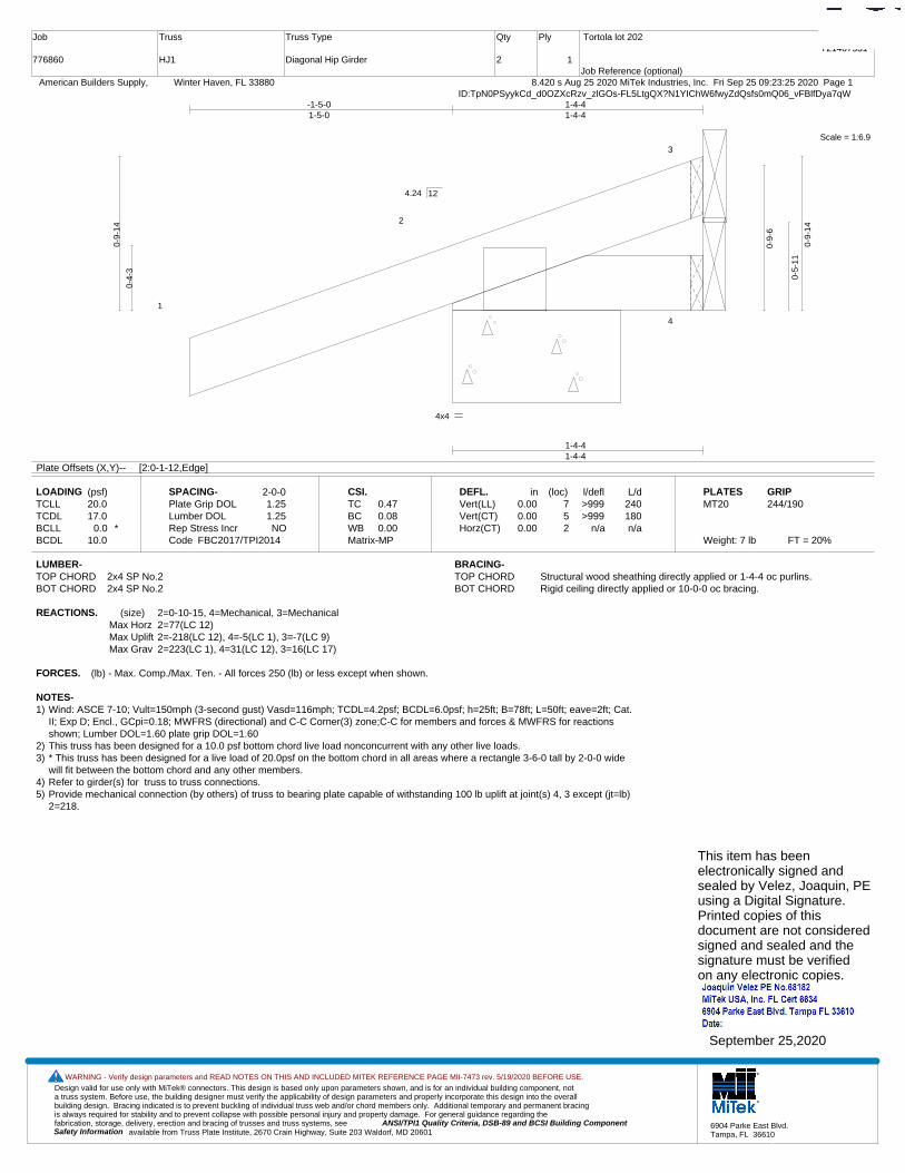
Design valid for use only with MiTek® connectors. This design is based only upon parameters shown, and is for an individual building component, not a truss system. Before use, the building designer must verify the applicability of design parameters and properly incorporate this design into the overall building design. Bracing indicated is to prevent buckling of individual truss web and/or chord members only. Additional temporary and permanent bracing is always required for stability and to prevent collapse with possible personal injury and property damage. For general guidance regarding the fabrication, storage, delivery, erection and bracing of trusses and truss systems, see ANSI/TPI1 Quality Criteria, DSB-89 and BCSI Building Component
available from Truss Plate Institute, 2670 Crain Highway, Suite 203 Waldorf, MD 20601Safety Information
WARNING - Verify design parameters and READ NOTES ON THIS AND INCLUDED MITEK REFERENCE PAGE MII-7473 rev. 5/19/2020 BEFORE USE.
6904 Parke East Blvd.Tampa, FL 36610
Job
776860
Truss
HJ1
Truss Type
Diagonal Hip Girder
Qty
2
Ply
1
Tortola lot 202
Job Reference (optional)
T21407531
8.420 s Aug 25 2020 MiTek Industries, Inc. Fri Sep 25 09:23:25 2020 Page 1 American Builders Supply, Winter Haven, FL 33880ID:TpN0PSyykCd_d0OZXcRzv_zlGOs-FL5LtgQX?N1YIChW6fwyZdQsfs0mQ06_vFBlfDya7qW
Scale = 1:6.9
1
2
3
4
4x4
1-4-41-4-4
-1-5-01-5-0
1-4-41-4-4
0-4-
3
0-9-
14
0-9-
6
0-5-
11
0-9-
14
4.24 12
Plate Offsets (X,Y)-- [2:0-1-12,Edge]
LOADING (psf)TCLLTCDLBCLLBCDL
20.017.0
0.0 *10.0
SPACING-Plate Grip DOLLumber DOL Rep Stress IncrCode
2-0-01.251.25NO
FBC2017/TPI2014
CSI.TCBCWBMatrix-MP
0.470.080.00
DEFL.Vert(LL)Vert(CT)Horz(CT)
in0.000.000.00
(loc)752
l/defl>999>999
n/a
L/d240180n/a
PLATESMT20
Weight: 7 lb FT = 20%
GRIP244/190
LUMBER-TOP CHORD 2x4 SP No.2BOT CHORD 2x4 SP No.2
BRACING-TOP CHORD Structural wood sheathing directly applied or 1-4-4 oc purlins.BOT CHORD Rigid ceiling directly applied or 10-0-0 oc bracing.
REACTIONS. (size) 2=0-10-15, 4=Mechanical, 3=MechanicalMax Horz 2=77(LC 12)Max Uplift 2=-218(LC 12), 4=-5(LC 1), 3=-7(LC 9)Max Grav 2=223(LC 1), 4=31(LC 12), 3=16(LC 17)
FORCES. (lb) - Max. Comp./Max. Ten. - All forces 250 (lb) or less except when shown.
NOTES-1) Wind: ASCE 7-10; Vult=150mph (3-second gust) Vasd=116mph; TCDL=4.2psf; BCDL=6.0psf; h=25ft; B=78ft; L=50ft; eave=2ft; Cat.
II; Exp D; Encl., GCpi=0.18; MWFRS (directional) and C-C Corner(3) zone;C-C for members and forces & MWFRS for reactionsshown; Lumber DOL=1.60 plate grip DOL=1.60
2) This truss has been designed for a 10.0 psf bottom chord live load nonconcurrent with any other live loads.3) * This truss has been designed for a live load of 20.0psf on the bottom chord in all areas where a rectangle 3-6-0 tall by 2-0-0 wide
will fit between the bottom chord and any other members.4) Refer to girder(s) for truss to truss connections.5) Provide mechanical connection (by others) of truss to bearing plate capable of withstanding 100 lb uplift at joint(s) 4, 3 except (jt=lb)
2=218.
This item has beenelectronically signed andsealed by Velez, Joaquin, PEusing a Digital Signature.Printed copies of thisdocument are not consideredsigned and sealed and thesignature must be verified on any electronic copies.
September 25,2020
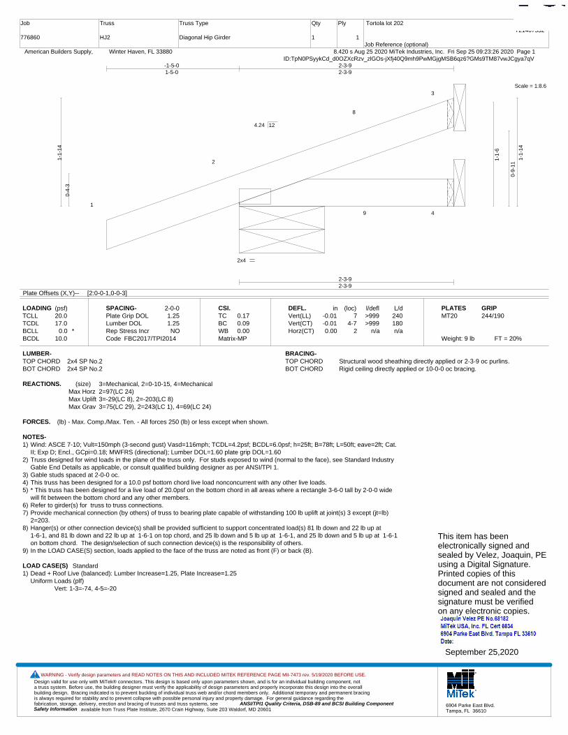
Design valid for use only with MiTek® connectors. This design is based only upon parameters shown, and is for an individual building component, not a truss system. Before use, the building designer must verify the applicability of design parameters and properly incorporate this design into the overall building design. Bracing indicated is to prevent buckling of individual truss web and/or chord members only. Additional temporary and permanent bracing is always required for stability and to prevent collapse with possible personal injury and property damage. For general guidance regarding the fabrication, storage, delivery, erection and bracing of trusses and truss systems, see ANSI/TPI1 Quality Criteria, DSB-89 and BCSI Building Component
available from Truss Plate Institute, 2670 Crain Highway, Suite 203 Waldorf, MD 20601Safety Information
WARNING - Verify design parameters and READ NOTES ON THIS AND INCLUDED MITEK REFERENCE PAGE MII-7473 rev. 5/19/2020 BEFORE USE.
6904 Parke East Blvd.Tampa, FL 36610
Job
776860
Truss
HJ2
Truss Type
Diagonal Hip Girder
Qty
1
Ply
1
Tortola lot 202
Job Reference (optional)
T21407532
8.420 s Aug 25 2020 MiTek Industries, Inc. Fri Sep 25 09:23:26 2020 Page 1 American Builders Supply, Winter Haven, FL 33880ID:TpN0PSyykCd_d0OZXcRzv_zlGOs-jXfj40Q9mh9PwMGjgMSB6qz6?GMs9TM87vwJCgya7qV
Scale = 1:8.6
1
2
8
3
9 4
2x4
2-3-92-3-9
-1-5-01-5-0
2-3-92-3-9
0-4-
3
1-1-
14
1-1-
6
0-9-
11
1-1-
14
4.24 12
Plate Offsets (X,Y)-- [2:0-0-1,0-0-3]
LOADING (psf)TCLLTCDLBCLLBCDL
20.017.0
0.0 *10.0
SPACING-Plate Grip DOLLumber DOL Rep Stress IncrCode
2-0-01.251.25NO
FBC2017/TPI2014
CSI.TCBCWBMatrix-MP
0.170.090.00
DEFL.Vert(LL)Vert(CT)Horz(CT)
in-0.01-0.010.00
(loc)7
4-72
l/defl>999>999
n/a
L/d240180n/a
PLATESMT20
Weight: 9 lb FT = 20%
GRIP244/190
LUMBER-TOP CHORD 2x4 SP No.2BOT CHORD 2x4 SP No.2
BRACING-TOP CHORD Structural wood sheathing directly applied or 2-3-9 oc purlins.BOT CHORD Rigid ceiling directly applied or 10-0-0 oc bracing.
REACTIONS. (size) 3=Mechanical, 2=0-10-15, 4=MechanicalMax Horz 2=97(LC 24)Max Uplift 3=-29(LC 8), 2=-203(LC 8)Max Grav 3=75(LC 29), 2=243(LC 1), 4=69(LC 24)
FORCES. (lb) - Max. Comp./Max. Ten. - All forces 250 (lb) or less except when shown.
NOTES-1) Wind: ASCE 7-10; Vult=150mph (3-second gust) Vasd=116mph; TCDL=4.2psf; BCDL=6.0psf; h=25ft; B=78ft; L=50ft; eave=2ft; Cat.
II; Exp D; Encl., GCpi=0.18; MWFRS (directional); Lumber DOL=1.60 plate grip DOL=1.602) Truss designed for wind loads in the plane of the truss only. For studs exposed to wind (normal to the face), see Standard Industry
Gable End Details as applicable, or consult qualified building designer as per ANSI/TPI 1.3) Gable studs spaced at 2-0-0 oc.4) This truss has been designed for a 10.0 psf bottom chord live load nonconcurrent with any other live loads.5) * This truss has been designed for a live load of 20.0psf on the bottom chord in all areas where a rectangle 3-6-0 tall by 2-0-0 wide
will fit between the bottom chord and any other members.6) Refer to girder(s) for truss to truss connections.7) Provide mechanical connection (by others) of truss to bearing plate capable of withstanding 100 lb uplift at joint(s) 3 except (jt=lb)
2=203.8) Hanger(s) or other connection device(s) shall be provided sufficient to support concentrated load(s) 81 lb down and 22 lb up at
1-6-1, and 81 lb down and 22 lb up at 1-6-1 on top chord, and 25 lb down and 5 lb up at 1-6-1, and 25 lb down and 5 lb up at 1-6-1on bottom chord. The design/selection of such connection device(s) is the responsibility of others.
9) In the LOAD CASE(S) section, loads applied to the face of the truss are noted as front (F) or back (B).
LOAD CASE(S) Standard1) Dead + Roof Live (balanced): Lumber Increase=1.25, Plate Increase=1.25
Uniform Loads (plf)Vert: 1-3=-74, 4-5=-20
This item has beenelectronically signed andsealed by Velez, Joaquin, PEusing a Digital Signature.Printed copies of thisdocument are not consideredsigned and sealed and thesignature must be verified on any electronic copies.
September 25,2020

Design valid for use only with MiTek® connectors. This design is based only upon parameters shown, and is for an individual building component, not a truss system. Before use, the building designer must verify the applicability of design parameters and properly incorporate this design into the overall building design. Bracing indicated is to prevent buckling of individual truss web and/or chord members only. Additional temporary and permanent bracing is always required for stability and to prevent collapse with possible personal injury and property damage. For general guidance regarding the fabrication, storage, delivery, erection and bracing of trusses and truss systems, see ANSI/TPI1 Quality Criteria, DSB-89 and BCSI Building Component
available from Truss Plate Institute, 2670 Crain Highway, Suite 203 Waldorf, MD 20601Safety Information
WARNING - Verify design parameters and READ NOTES ON THIS AND INCLUDED MITEK REFERENCE PAGE MII-7473 rev. 5/19/2020 BEFORE USE.
6904 Parke East Blvd.Tampa, FL 36610
Job
776860
Truss
HJ3
Truss Type
Diagonal Hip Girder
Qty
2
Ply
1
Tortola lot 202
Job Reference (optional)
T21407533
8.420 s Aug 25 2020 MiTek Industries, Inc. Fri Sep 25 09:23:27 2020 Page 1 American Builders Supply, Winter Haven, FL 33880ID:TpN0PSyykCd_d0OZXcRzv_zlGOs-BjD5IMRnX?HGYWrvE4zQe2WFOgg8uvcHMYgsk6ya7qU
Scale: 1"=1'
1
2
8
3
9 4
2x4
4-2-34-2-3
-1-5-01-5-0
2-3-102-3-10
4-2-31-10-8
0-4-
3
1-9-
14
0-4-
4
1-5-
10 1-9-
14
4.24 12
LOADING (psf)TCLLTCDLBCLLBCDL
20.017.0
0.0 *10.0
SPACING-Plate Grip DOLLumber DOL Rep Stress IncrCode
2-0-01.251.25NO
FBC2017/TPI2014
CSI.TCBCWBMatrix-MP
0.260.210.00
DEFL.Vert(LL)Vert(CT)Horz(CT)
in-0.02-0.040.00
(loc)4-74-7
2
l/defl>999>999
n/a
L/d240180n/a
PLATESMT20
Weight: 15 lb FT = 20%
GRIP244/190
LUMBER-TOP CHORD 2x4 SP No.2BOT CHORD 2x4 SP No.2
BRACING-TOP CHORD Structural wood sheathing directly applied or 4-2-3 oc purlins.BOT CHORD Rigid ceiling directly applied or 10-0-0 oc bracing.
REACTIONS. (size) 3=Mechanical, 2=0-5-5, 4=MechanicalMax Horz 2=139(LC 24)Max Uplift 3=-88(LC 8), 2=-215(LC 8)Max Grav 3=130(LC 28), 2=323(LC 28), 4=77(LC 3)
FORCES. (lb) - Max. Comp./Max. Ten. - All forces 250 (lb) or less except when shown.
NOTES-1) Wind: ASCE 7-10; Vult=150mph (3-second gust) Vasd=116mph; TCDL=4.2psf; BCDL=6.0psf; h=25ft; B=78ft; L=50ft; eave=2ft; Cat.
II; Exp D; Encl., GCpi=0.18; MWFRS (directional); Lumber DOL=1.60 plate grip DOL=1.602) This truss has been designed for a 10.0 psf bottom chord live load nonconcurrent with any other live loads.3) * This truss has been designed for a live load of 20.0psf on the bottom chord in all areas where a rectangle 3-6-0 tall by 2-0-0 wide
will fit between the bottom chord and any other members.4) Refer to girder(s) for truss to truss connections.5) Provide mechanical connection (by others) of truss to bearing plate capable of withstanding 100 lb uplift at joint(s) 3 except (jt=lb)
2=215.6) Hanger(s) or other connection device(s) shall be provided sufficient to support concentrated load(s) 103 lb down and 26 lb up at
1-6-1, and 103 lb down and 26 lb up at 1-6-1 on top chord, and 25 lb down and 5 lb up at 1-6-1, and 25 lb down and 5 lb up at 1-6-1 on bottom chord. The design/selection of such connection device(s) is the responsibility of others.
7) In the LOAD CASE(S) section, loads applied to the face of the truss are noted as front (F) or back (B).
LOAD CASE(S) Standard1) Dead + Roof Live (balanced): Lumber Increase=1.25, Plate Increase=1.25
Uniform Loads (plf)Vert: 1-3=-74, 4-5=-20
This item has beenelectronically signed andsealed by Velez, Joaquin, PEusing a Digital Signature.Printed copies of thisdocument are not consideredsigned and sealed and thesignature must be verified on any electronic copies.
September 25,2020

Design valid for use only with MiTek® connectors. This design is based only upon parameters shown, and is for an individual building component, not a truss system. Before use, the building designer must verify the applicability of design parameters and properly incorporate this design into the overall building design. Bracing indicated is to prevent buckling of individual truss web and/or chord members only. Additional temporary and permanent bracing is always required for stability and to prevent collapse with possible personal injury and property damage. For general guidance regarding the fabrication, storage, delivery, erection and bracing of trusses and truss systems, see ANSI/TPI1 Quality Criteria, DSB-89 and BCSI Building Component
available from Truss Plate Institute, 2670 Crain Highway, Suite 203 Waldorf, MD 20601Safety Information
WARNING - Verify design parameters and READ NOTES ON THIS AND INCLUDED MITEK REFERENCE PAGE MII-7473 rev. 5/19/2020 BEFORE USE.
6904 Parke East Blvd.Tampa, FL 36610
Job
776860
Truss
HJ5
Truss Type
Diagonal Hip Girder
Qty
2
Ply
1
Tortola lot 202
Job Reference (optional)
T21407534
8.420 s Aug 25 2020 MiTek Industries, Inc. Fri Sep 25 09:23:28 2020 Page 1 American Builders Supply, Winter Haven, FL 33880ID:TpN0PSyykCd_d0OZXcRzv_zlGOs-fwnUViSQIIP79gQ5onUfBF2GE4v8dMsQbCPPGYya7qT
Scale = 1:16.7
1
2
8
9
3
10 11 4
3x4
7-0-27-0-2
-1-5-01-5-0
3-8-103-8-10
7-0-23-3-8
0-4-
3
2-9-
14
0-4-
4
2-5-
11 2-9-
14
4.24 12
LOADING (psf)TCLLTCDLBCLLBCDL
20.017.0
0.0 *10.0
SPACING-Plate Grip DOLLumber DOL Rep Stress IncrCode
2-0-01.251.25NO
FBC2017/TPI2014
CSI.TCBCWBMatrix-MP
0.960.680.00
DEFL.Vert(LL)Vert(CT)Horz(CT)
in0.16
-0.280.01
(loc)4-74-7
2
l/defl>530>295
n/a
L/d240180n/a
PLATESMT20
Weight: 24 lb FT = 20%
GRIP244/190
LUMBER-TOP CHORD 2x4 SP No.2BOT CHORD 2x4 SP No.2
BRACING-TOP CHORD Structural wood sheathing directly applied or 6-0-0 oc purlins.BOT CHORD Rigid ceiling directly applied or 10-0-0 oc bracing.
REACTIONS. (size) 3=Mechanical, 2=0-5-5, 4=MechanicalMax Horz 2=201(LC 8)Max Uplift 3=-167(LC 8), 2=-254(LC 8)Max Grav 3=240(LC 28), 2=473(LC 28), 4=139(LC 3)
FORCES. (lb) - Max. Comp./Max. Ten. - All forces 250 (lb) or less except when shown.
NOTES-1) Wind: ASCE 7-10; Vult=150mph (3-second gust) Vasd=116mph; TCDL=4.2psf; BCDL=6.0psf; h=25ft; B=78ft; L=50ft; eave=2ft; Cat.
II; Exp D; Encl., GCpi=0.18; MWFRS (directional); Lumber DOL=1.60 plate grip DOL=1.602) This truss has been designed for a 10.0 psf bottom chord live load nonconcurrent with any other live loads.3) * This truss has been designed for a live load of 20.0psf on the bottom chord in all areas where a rectangle 3-6-0 tall by 2-0-0 wide
will fit between the bottom chord and any other members.4) Refer to girder(s) for truss to truss connections.5) Provide mechanical connection (by others) of truss to bearing plate capable of withstanding 100 lb uplift at joint(s) except (jt=lb)
3=167, 2=254.6) Hanger(s) or other connection device(s) shall be provided sufficient to support concentrated load(s) 103 lb down and 26 lb up at
1-6-1, 103 lb down and 26 lb up at 1-6-1, and 152 lb down and 99 lb up at 4-4-0, and 152 lb down and 99 lb up at 4-4-0 on topchord, and 25 lb down and 5 lb up at 1-6-1, 25 lb down and 5 lb up at 1-6-1, and 21 lb down at 4-4-0, and 21 lb down at 4-4-0 onbottom chord. The design/selection of such connection device(s) is the responsibility of others.
7) In the LOAD CASE(S) section, loads applied to the face of the truss are noted as front (F) or back (B).
LOAD CASE(S) Standard1) Dead + Roof Live (balanced): Lumber Increase=1.25, Plate Increase=1.25
Uniform Loads (plf)Vert: 1-3=-74, 4-5=-20
Concentrated Loads (lb)Vert: 11=-21(F=-11, B=-11)
This item has beenelectronically signed andsealed by Velez, Joaquin, PEusing a Digital Signature.Printed copies of thisdocument are not consideredsigned and sealed and thesignature must be verified on any electronic copies.
September 25,2020
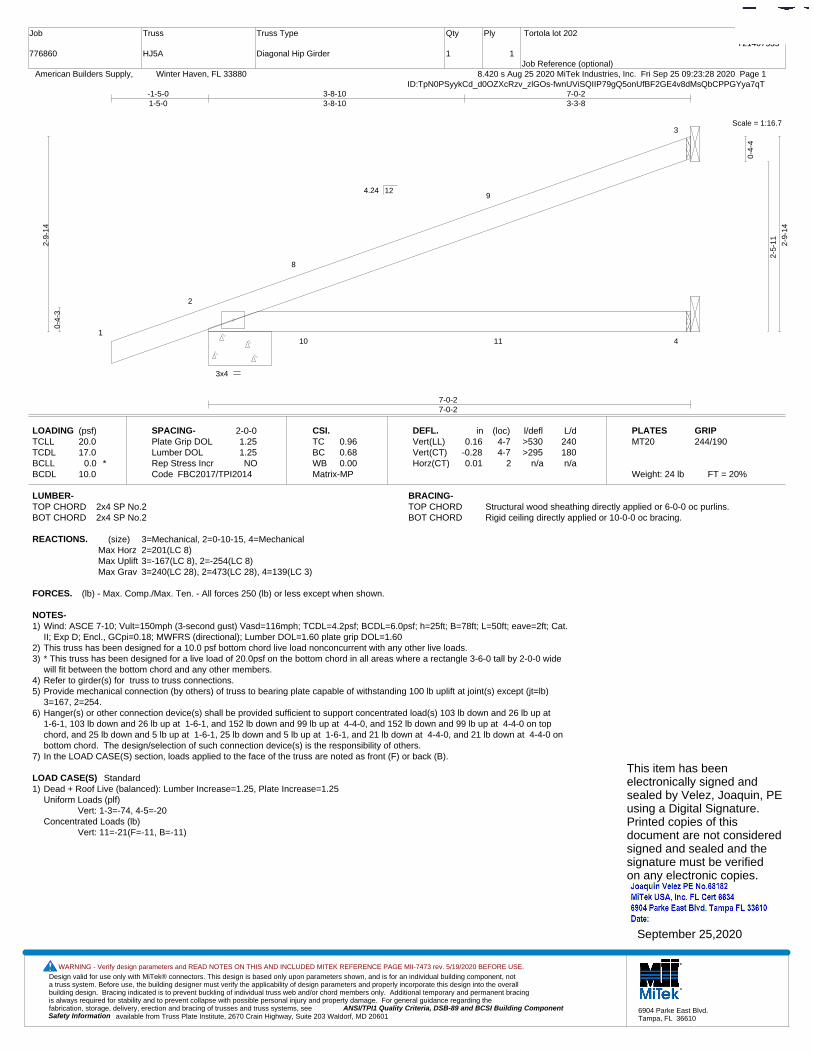
Design valid for use only with MiTek® connectors. This design is based only upon parameters shown, and is for an individual building component, not a truss system. Before use, the building designer must verify the applicability of design parameters and properly incorporate this design into the overall building design. Bracing indicated is to prevent buckling of individual truss web and/or chord members only. Additional temporary and permanent bracing is always required for stability and to prevent collapse with possible personal injury and property damage. For general guidance regarding the fabrication, storage, delivery, erection and bracing of trusses and truss systems, see ANSI/TPI1 Quality Criteria, DSB-89 and BCSI Building Component
available from Truss Plate Institute, 2670 Crain Highway, Suite 203 Waldorf, MD 20601Safety Information
WARNING - Verify design parameters and READ NOTES ON THIS AND INCLUDED MITEK REFERENCE PAGE MII-7473 rev. 5/19/2020 BEFORE USE.
6904 Parke East Blvd.Tampa, FL 36610
Job
776860
Truss
HJ5A
Truss Type
Diagonal Hip Girder
Qty
1
Ply
1
Tortola lot 202
Job Reference (optional)
T21407535
8.420 s Aug 25 2020 MiTek Industries, Inc. Fri Sep 25 09:23:28 2020 Page 1 American Builders Supply, Winter Haven, FL 33880ID:TpN0PSyykCd_d0OZXcRzv_zlGOs-fwnUViSQIIP79gQ5onUfBF2GE4v8dMsQbCPPGYya7qT
Scale = 1:16.7
1
2
8
9
3
10 11 4
3x4
7-0-27-0-2
-1-5-01-5-0
3-8-103-8-10
7-0-23-3-8
0-4-
3
2-9-
14
0-4-
4
2-5-
11 2-9-
14
4.24 12
LOADING (psf)TCLLTCDLBCLLBCDL
20.017.0
0.0 *10.0
SPACING-Plate Grip DOLLumber DOL Rep Stress IncrCode
2-0-01.251.25NO
FBC2017/TPI2014
CSI.TCBCWBMatrix-MP
0.960.680.00
DEFL.Vert(LL)Vert(CT)Horz(CT)
in0.16
-0.280.01
(loc)4-74-7
2
l/defl>530>295
n/a
L/d240180n/a
PLATESMT20
Weight: 24 lb FT = 20%
GRIP244/190
LUMBER-TOP CHORD 2x4 SP No.2BOT CHORD 2x4 SP No.2
BRACING-TOP CHORD Structural wood sheathing directly applied or 6-0-0 oc purlins.BOT CHORD Rigid ceiling directly applied or 10-0-0 oc bracing.
REACTIONS. (size) 3=Mechanical, 2=0-10-15, 4=MechanicalMax Horz 2=201(LC 8)Max Uplift 3=-167(LC 8), 2=-254(LC 8)Max Grav 3=240(LC 28), 2=473(LC 28), 4=139(LC 3)
FORCES. (lb) - Max. Comp./Max. Ten. - All forces 250 (lb) or less except when shown.
NOTES-1) Wind: ASCE 7-10; Vult=150mph (3-second gust) Vasd=116mph; TCDL=4.2psf; BCDL=6.0psf; h=25ft; B=78ft; L=50ft; eave=2ft; Cat.
II; Exp D; Encl., GCpi=0.18; MWFRS (directional); Lumber DOL=1.60 plate grip DOL=1.602) This truss has been designed for a 10.0 psf bottom chord live load nonconcurrent with any other live loads.3) * This truss has been designed for a live load of 20.0psf on the bottom chord in all areas where a rectangle 3-6-0 tall by 2-0-0 wide
will fit between the bottom chord and any other members.4) Refer to girder(s) for truss to truss connections.5) Provide mechanical connection (by others) of truss to bearing plate capable of withstanding 100 lb uplift at joint(s) except (jt=lb)
3=167, 2=254.6) Hanger(s) or other connection device(s) shall be provided sufficient to support concentrated load(s) 103 lb down and 26 lb up at
1-6-1, 103 lb down and 26 lb up at 1-6-1, and 152 lb down and 99 lb up at 4-4-0, and 152 lb down and 99 lb up at 4-4-0 on topchord, and 25 lb down and 5 lb up at 1-6-1, 25 lb down and 5 lb up at 1-6-1, and 21 lb down at 4-4-0, and 21 lb down at 4-4-0 onbottom chord. The design/selection of such connection device(s) is the responsibility of others.
7) In the LOAD CASE(S) section, loads applied to the face of the truss are noted as front (F) or back (B).
LOAD CASE(S) Standard1) Dead + Roof Live (balanced): Lumber Increase=1.25, Plate Increase=1.25
Uniform Loads (plf)Vert: 1-3=-74, 4-5=-20
Concentrated Loads (lb)Vert: 11=-21(F=-11, B=-11)
This item has beenelectronically signed andsealed by Velez, Joaquin, PEusing a Digital Signature.Printed copies of thisdocument are not consideredsigned and sealed and thesignature must be verified on any electronic copies.
September 25,2020

Design valid for use only with MiTek® connectors. This design is based only upon parameters shown, and is for an individual building component, not a truss system. Before use, the building designer must verify the applicability of design parameters and properly incorporate this design into the overall building design. Bracing indicated is to prevent buckling of individual truss web and/or chord members only. Additional temporary and permanent bracing is always required for stability and to prevent collapse with possible personal injury and property damage. For general guidance regarding the fabrication, storage, delivery, erection and bracing of trusses and truss systems, see ANSI/TPI1 Quality Criteria, DSB-89 and BCSI Building Component
available from Truss Plate Institute, 2670 Crain Highway, Suite 203 Waldorf, MD 20601Safety Information
WARNING - Verify design parameters and READ NOTES ON THIS AND INCLUDED MITEK REFERENCE PAGE MII-7473 rev. 5/19/2020 BEFORE USE.
6904 Parke East Blvd.Tampa, FL 36610
Job
776860
Truss
HJ7A
Truss Type
Diagonal Hip Girder
Qty
2
Ply
1
Tortola lot 202
Job Reference (optional)
T21407536
8.420 s Aug 25 2020 MiTek Industries, Inc. Fri Sep 25 09:23:29 2020 Page 1 American Builders Supply, Winter Haven, FL 33880ID:TpN0PSyykCd_d0OZXcRzv_zlGOs-86Lsj2T23cX_nq_HLV?ujTbXZUGwMiBaps9zp_ya7qS
Scale = 1:21.5
1
2
3
76
11
12
13
4
14 15 16 5
2x4
3x4
2x4 3x4
5-1-155-1-15
9-10-54-8-5
9-10-130-0-8
-1-5-01-5-0
5-1-155-1-15
9-10-134-8-13
0-4-
3
3-10
-3
3-5-
15 3-10
-3
4.24 12
LOADING (psf)TCLLTCDLBCLLBCDL
20.017.0
0.0 *10.0
SPACING-Plate Grip DOLLumber DOL Rep Stress IncrCode
2-0-01.251.25NO
FBC2017/TPI2014
CSI.TCBCWBMatrix-MS
0.540.580.51
DEFL.Vert(LL)Vert(CT)Horz(CT)
in-0.03-0.090.01
(loc)6-76-7
5
l/defl>999>999
n/a
L/d240180n/a
PLATESMT20
Weight: 42 lb FT = 20%
GRIP244/190
LUMBER-TOP CHORD 2x4 SP No.2BOT CHORD 2x4 SP No.2WEBS 2x4 SP No.3
BRACING-TOP CHORD Structural wood sheathing directly applied or 5-4-4 oc purlins.BOT CHORD Rigid ceiling directly applied or 8-9-2 oc bracing.
REACTIONS. (size) 4=Mechanical, 2=0-8-0, 5=MechanicalMax Horz 2=265(LC 8)Max Uplift 4=-152(LC 8), 2=-325(LC 8), 5=-151(LC 8)Max Grav 4=174(LC 28), 2=672(LC 28), 5=462(LC 28)
FORCES. (lb) - Max. Comp./Max. Ten. - All forces 250 (lb) or less except when shown.TOP CHORD 2-3=-1142/319BOT CHORD 2-7=-452/1008, 6-7=-452/1008WEBS 3-7=0/315, 3-6=-1093/490
NOTES-1) Wind: ASCE 7-10; Vult=150mph (3-second gust) Vasd=116mph; TCDL=4.2psf; BCDL=6.0psf; h=25ft; B=78ft; L=50ft; eave=6ft; Cat.
II; Exp D; Encl., GCpi=0.18; MWFRS (directional); Lumber DOL=1.60 plate grip DOL=1.602) This truss has been designed for a 10.0 psf bottom chord live load nonconcurrent with any other live loads.3) * This truss has been designed for a live load of 20.0psf on the bottom chord in all areas where a rectangle 3-6-0 tall by 2-0-0 wide
will fit between the bottom chord and any other members.4) Refer to girder(s) for truss to truss connections.5) Provide mechanical connection (by others) of truss to bearing plate capable of withstanding 100 lb uplift at joint(s) except (jt=lb)
4=152, 2=325, 5=151.6) Hanger(s) or other connection device(s) shall be provided sufficient to support concentrated load(s) 103 lb down and 26 lb up at
1-6-1, 103 lb down and 26 lb up at 1-6-1, 152 lb down and 99 lb up at 4-4-0, 152 lb down and 99 lb up at 4-4-0, and 211 lb downand 170 lb up at 7-1-15, and 211 lb down and 170 lb up at 7-1-15 on top chord, and 25 lb down and 5 lb up at 1-6-1, 25 lb downand 5 lb up at 1-6-1, 21 lb down at 4-4-0, 21 lb down at 4-4-0, and 49 lb down at 7-1-15, and 49 lb down at 7-1-15 on bottomchord. The design/selection of such connection device(s) is the responsibility of others.
7) In the LOAD CASE(S) section, loads applied to the face of the truss are noted as front (F) or back (B).
LOAD CASE(S) Standard1) Dead + Roof Live (balanced): Lumber Increase=1.25, Plate Increase=1.25
Uniform Loads (plf)Vert: 1-4=-74, 5-8=-20
Concentrated Loads (lb)Vert: 13=-102(F=-51, B=-51) 15=-21(F=-11, B=-11) 16=-82(F=-41, B=-41)
This item has beenelectronically signed andsealed by Velez, Joaquin, PEusing a Digital Signature.Printed copies of thisdocument are not consideredsigned and sealed and thesignature must be verified on any electronic copies.
September 25,2020

Design valid for use only with MiTek® connectors. This design is based only upon parameters shown, and is for an individual building component, not a truss system. Before use, the building designer must verify the applicability of design parameters and properly incorporate this design into the overall building design. Bracing indicated is to prevent buckling of individual truss web and/or chord members only. Additional temporary and permanent bracing is always required for stability and to prevent collapse with possible personal injury and property damage. For general guidance regarding the fabrication, storage, delivery, erection and bracing of trusses and truss systems, see ANSI/TPI1 Quality Criteria, DSB-89 and BCSI Building Component
available from Truss Plate Institute, 2670 Crain Highway, Suite 203 Waldorf, MD 20601Safety Information
WARNING - Verify design parameters and READ NOTES ON THIS AND INCLUDED MITEK REFERENCE PAGE MII-7473 rev. 5/19/2020 BEFORE USE.
6904 Parke East Blvd.Tampa, FL 36610
Job
776860
Truss
HJ7A1
Truss Type
Diagonal Hip Girder
Qty
1
Ply
1
Tortola lot 202
Job Reference (optional)
T21407537
8.420 s Aug 25 2020 MiTek Industries, Inc. Fri Sep 25 09:23:30 2020 Page 1 American Builders Supply, Winter Haven, FL 33880ID:TpN0PSyykCd_d0OZXcRzv_zlGOs-cIvEwOTgqwfrPzZUvCW7Gg8jAten5Bxj2WuWLRya7qR
Scale = 1:22.6
1
2
3
7
6
11
12
13
4
14 15 16
53x4
3x4
2x4
3x4
0-3-8
5-10-55-10-5
9-4-73-6-1
9-10-10-5-10
-1-5-01-5-0
5-10-55-10-5
9-10-13-11-11
0-4-
3
3-9-
14
0-4-
4
3-5-
11
3-9-
14
4.24 12
LOADING (psf)TCLLTCDLBCLLBCDL
20.017.0
0.0 *10.0
SPACING-Plate Grip DOLLumber DOL Rep Stress IncrCode
2-0-01.251.25NO
FBC2017/TPI2014
CSI.TCBCWBMatrix-MS
0.480.470.35
DEFL.Vert(LL)Vert(CT)Horz(CT)
in0.10
-0.09-0.01
(loc)7-107-10
5
l/defl>999>999
n/a
L/d240180n/a
PLATESMT20
Weight: 41 lb FT = 20%
GRIP244/190
LUMBER-TOP CHORD 2x4 SP No.2BOT CHORD 2x4 SP No.2WEBS 2x4 SP No.3
BRACING-TOP CHORD Structural wood sheathing directly applied or 5-8-8 oc purlins.BOT CHORD Rigid ceiling directly applied or 6-10-9 oc bracing.
REACTIONS. All bearings Mechanical except (jt=length) 2=0-10-15, 6=0-11-5.(lb) - Max Horz 2=264(LC 8)
Max Uplift All uplift 100 lb or less at joint(s) except 4=-108(LC 8), 2=-529(LC 8), 5=-303(LC 3), 6=-516(LC 8)Max Grav All reactions 250 lb or less at joint(s) 4, 5 except 2=646(LC 28), 6=743(LC 1)
FORCES. (lb) - Max. Comp./Max. Ten. - All forces 250 (lb) or less except when shown.TOP CHORD 2-3=-961/549BOT CHORD 2-7=-662/826, 6-7=-662/826WEBS 3-7=-169/271, 3-6=-952/764
NOTES-1) Wind: ASCE 7-10; Vult=150mph (3-second gust) Vasd=116mph; TCDL=4.2psf; BCDL=6.0psf; h=25ft; B=78ft; L=50ft; eave=2ft; Cat.
II; Exp D; Encl., GCpi=0.18; MWFRS (directional); porch left exposed; Lumber DOL=1.60 plate grip DOL=1.602) This truss has been designed for a 10.0 psf bottom chord live load nonconcurrent with any other live loads.3) * This truss has been designed for a live load of 20.0psf on the bottom chord in all areas where a rectangle 3-6-0 tall by 2-0-0 wide
will fit between the bottom chord and any other members.4) Refer to girder(s) for truss to truss connections.5) Provide mechanical connection (by others) of truss to bearing plate capable of withstanding 108 lb uplift at joint 4, 529 lb uplift at
joint 2, 303 lb uplift at joint 5 and 516 lb uplift at joint 6.6) Hanger(s) or other connection device(s) shall be provided sufficient to support concentrated load(s) 103 lb down and 26 lb up at
1-6-1, 103 lb down and 26 lb up at 1-6-1, 152 lb down and 99 lb up at 4-4-0, 152 lb down and 99 lb up at 4-4-0, and 211 lb downand 170 lb up at 7-1-15, and 211 lb down and 170 lb up at 7-1-15 on top chord, and 89 lb down and 5 lb up at 1-6-1, 89 lb downand 5 lb up at 1-6-1, 85 lb down at 4-4-0, 85 lb down at 4-4-0, and 113 lb down at 7-1-15, and 113 lb down at 7-1-15 on bottomchord. The design/selection of such connection device(s) is the responsibility of others.
7) In the LOAD CASE(S) section, loads applied to the face of the truss are noted as front (F) or back (B).
LOAD CASE(S) Standard1) Dead + Roof Live (balanced): Lumber Increase=1.25, Plate Increase=1.25
Uniform Loads (plf)Vert: 1-4=-74, 5-8=-20
Concentrated Loads (lb)Vert: 13=-102(F=-51, B=-51) 15=-21(F=-11, B=-11) 16=-82(F=-41, B=-41)
This item has beenelectronically signed andsealed by Velez, Joaquin, PEusing a Digital Signature.Printed copies of thisdocument are not consideredsigned and sealed and thesignature must be verified on any electronic copies.
September 25,2020

Design valid for use only with MiTek® connectors. This design is based only upon parameters shown, and is for an individual building component, not a truss system. Before use, the building designer must verify the applicability of design parameters and properly incorporate this design into the overall building design. Bracing indicated is to prevent buckling of individual truss web and/or chord members only. Additional temporary and permanent bracing is always required for stability and to prevent collapse with possible personal injury and property damage. For general guidance regarding the fabrication, storage, delivery, erection and bracing of trusses and truss systems, see ANSI/TPI1 Quality Criteria, DSB-89 and BCSI Building Component
available from Truss Plate Institute, 2670 Crain Highway, Suite 203 Waldorf, MD 20601Safety Information
WARNING - Verify design parameters and READ NOTES ON THIS AND INCLUDED MITEK REFERENCE PAGE MII-7473 rev. 5/19/2020 BEFORE USE.
6904 Parke East Blvd.Tampa, FL 36610
Job
776860
Truss
HJ7D
Truss Type
Diagonal Hip Girder
Qty
1
Ply
1
Tortola lot 202
Job Reference (optional)
T21407538
8.420 s Aug 25 2020 MiTek Industries, Inc. Fri Sep 25 09:23:31 2020 Page 1 American Builders Supply, Winter Haven, FL 33880ID:TpN0PSyykCd_d0OZXcRzv_zlGOs-4UTc8kUIbDni078gTv1MpugvhHz_qevtHAe3ttya7qQ
Scale = 1:20.8
1
2
3
76
11
12
13
4
14 15 16
52x4
3x4
2x4
3x4
0-3-8
5-5-45-5-4
9-5-134-0-9
-1-5-01-5-0
5-5-45-5-4
9-5-134-0-9
0-4-
3
3-8-
6
0-4-
4
3-4-
3 3-8-
6
4.24 12
LOADING (psf)TCLLTCDLBCLLBCDL
20.017.0
0.0 *10.0
SPACING-Plate Grip DOLLumber DOL Rep Stress IncrCode
2-0-01.251.25NO
FBC2017/TPI2014
CSI.TCBCWBMatrix-MS
0.430.480.36
DEFL.Vert(LL)Vert(CT)Horz(CT)
in-0.04-0.060.01
(loc)7-107-10
5
l/defl>999>999
n/a
L/d240180n/a
PLATESMT20
Weight: 40 lb FT = 20%
GRIP244/190
LUMBER-TOP CHORD 2x4 SP No.2BOT CHORD 2x4 SP No.2WEBS 2x4 SP No.3
BRACING-TOP CHORD Structural wood sheathing directly applied or 5-7-4 oc purlins.BOT CHORD Rigid ceiling directly applied or 8-8-11 oc bracing.
REACTIONS. (size) 4=Mechanical, 2=0-10-15, 5=MechanicalMax Horz 2=256(LC 8)Max Uplift 4=-133(LC 8), 2=-338(LC 8), 5=-204(LC 8)Max Grav 4=147(LC 28), 2=650(LC 28), 5=486(LC 28)
FORCES. (lb) - Max. Comp./Max. Ten. - All forces 250 (lb) or less except when shown.TOP CHORD 2-3=-1026/340BOT CHORD 2-7=-450/889, 6-7=-450/889WEBS 3-7=0/315, 3-6=-1003/508
NOTES-1) Wind: ASCE 7-10; Vult=150mph (3-second gust) Vasd=116mph; TCDL=4.2psf; BCDL=6.0psf; h=25ft; B=78ft; L=50ft; eave=2ft; Cat.
II; Exp D; Encl., GCpi=0.18; MWFRS (directional); porch right exposed; Lumber DOL=1.60 plate grip DOL=1.602) This truss has been designed for a 10.0 psf bottom chord live load nonconcurrent with any other live loads.3) * This truss has been designed for a live load of 20.0psf on the bottom chord in all areas where a rectangle 3-6-0 tall by 2-0-0 wide
will fit between the bottom chord and any other members.4) Refer to girder(s) for truss to truss connections.5) Provide mechanical connection (by others) of truss to bearing plate capable of withstanding 133 lb uplift at joint 4, 338 lb uplift at
joint 2 and 204 lb uplift at joint 5.6) Hanger(s) or other connection device(s) shall be provided sufficient to support concentrated load(s) 103 lb down and 26 lb up at
1-6-1, 103 lb down and 26 lb up at 1-6-1, 156 lb down and 108 lb up at 4-4-0, 152 lb down and 99 lb up at 4-4-0, and 213 lb downand 176 lb up at 7-1-15, and 211 lb down and 170 lb up at 7-1-15 on top chord, and 25 lb down and 5 lb up at 1-6-1, 25 lb downand 5 lb up at 1-6-1, 26 lb down and 23 lb up at 4-4-0, 21 lb down at 4-4-0, and 52 lb down and 33 lb up at 7-1-15, and 49 lb downat 7-1-15 on bottom chord. The design/selection of such connection device(s) is the responsibility of others.
7) In the LOAD CASE(S) section, loads applied to the face of the truss are noted as front (F) or back (B).
LOAD CASE(S) Standard1) Dead + Roof Live (balanced): Lumber Increase=1.25, Plate Increase=1.25
Uniform Loads (plf)Vert: 1-4=-74, 5-8=-20
Concentrated Loads (lb)Vert: 13=-105(F=-51, B=-54) 15=-28(F=-11, B=-17) 16=-86(F=-41, B=-45)
This item has beenelectronically signed andsealed by Velez, Joaquin, PEusing a Digital Signature.Printed copies of thisdocument are not consideredsigned and sealed and thesignature must be verified on any electronic copies.
September 25,2020

Design valid for use only with MiTek® connectors. This design is based only upon parameters shown, and is for an individual building component, not a truss system. Before use, the building designer must verify the applicability of design parameters and properly incorporate this design into the overall building design. Bracing indicated is to prevent buckling of individual truss web and/or chord members only. Additional temporary and permanent bracing is always required for stability and to prevent collapse with possible personal injury and property damage. For general guidance regarding the fabrication, storage, delivery, erection and bracing of trusses and truss systems, see ANSI/TPI1 Quality Criteria, DSB-89 and BCSI Building Component
available from Truss Plate Institute, 2670 Crain Highway, Suite 203 Waldorf, MD 20601Safety Information
WARNING - Verify design parameters and READ NOTES ON THIS AND INCLUDED MITEK REFERENCE PAGE MII-7473 rev. 5/19/2020 BEFORE USE.
6904 Parke East Blvd.Tampa, FL 36610
Job
776860
Truss
HJ7G
Truss Type
Diagonal Hip Girder
Qty
2
Ply
1
Tortola lot 202
Job Reference (optional)
T21407539
8.420 s Aug 25 2020 MiTek Industries, Inc. Fri Sep 25 09:23:32 2020 Page 1 American Builders Supply, Winter Haven, FL 33880ID:TpN0PSyykCd_d0OZXcRzv_zlGOs-Yh0_L4VwMXvZeHjs0dYbL5D0mhD6Z6t0WqNdPJya7qP
Scale = 1:22.7
1
2
3
4
1110
98
7
15
16
5
17
18 19
6
2x4
10x10 3x8
3x4
2x4 3x4
0-3-8
0-2-0
1-11-121-11-12
3-2-141-3-2
6-9-153-7-1
9-10-13-0-2
-1-5-01-5-0
1-11-121-11-12
3-2-141-3-2
6-9-153-7-1
9-10-13-0-2
0-4-
3
3-9-
14
0-4-
4
3-5-
11
3-1-
14
0-8-
0
4.24 12
Plate Offsets (X,Y)-- [3:0-6-0,0-1-8], [9:0-5-0,0-2-12]
LOADING (psf)TCLLTCDLBCLLBCDL
20.017.0
0.0 *10.0
SPACING-Plate Grip DOLLumber DOL Rep Stress IncrCode
2-0-01.251.25NO
FBC2017/TPI2014
CSI.TCBCWBMatrix-MS
0.670.870.32
DEFL.Vert(LL)Vert(CT)Horz(CT)
in0.22
-0.300.07
(loc)1010
6
l/defl>523>393
n/a
L/d240180n/a
PLATESMT20
Weight: 44 lb FT = 20%
GRIP244/190
LUMBER-TOP CHORD 2x4 SP No.2BOT CHORD 2x4 SP No.2 *Except*
3-6: 2x4 SP M 30WEBS 2x4 SP No.3
BRACING-TOP CHORD Structural wood sheathing directly applied or 4-3-8 oc purlins.BOT CHORD Rigid ceiling directly applied or 7-11-11 oc bracing.
REACTIONS. (size) 5=Mechanical, 2=0-5-5, 6=MechanicalMax Horz 2=264(LC 8)Max Uplift 5=-80(LC 24), 2=-368(LC 8), 6=-316(LC 8)Max Grav 5=54(LC 13), 2=692(LC 28), 6=618(LC 28)
FORCES. (lb) - Max. Comp./Max. Ten. - All forces 250 (lb) or less except when shown.TOP CHORD 3-13=-1333/417, 3-4=-1230/509BOT CHORD 2-11=-555/1163, 9-11=-179/462, 3-9=-375/609, 8-9=-604/1112, 7-8=-604/1112WEBS 4-8=-224/588, 4-7=-1333/724, 3-11=-756/375
NOTES-1) Wind: ASCE 7-10; Vult=150mph (3-second gust) Vasd=116mph; TCDL=4.2psf; BCDL=6.0psf; h=25ft; B=78ft; L=50ft; eave=2ft; Cat.
II; Exp D; Encl., GCpi=0.18; MWFRS (directional); Lumber DOL=1.60 plate grip DOL=1.602) This truss has been designed for a 10.0 psf bottom chord live load nonconcurrent with any other live loads.3) * This truss has been designed for a live load of 20.0psf on the bottom chord in all areas where a rectangle 3-6-0 tall by 2-0-0 wide
will fit between the bottom chord and any other members.4) Refer to girder(s) for truss to truss connections.5) Provide mechanical connection (by others) of truss to bearing plate capable of withstanding 80 lb uplift at joint 5, 368 lb uplift at joint
2 and 316 lb uplift at joint 6.6) Hanger(s) or other connection device(s) shall be provided sufficient to support concentrated load(s) 103 lb down and 26 lb up at
1-6-1, 103 lb down and 26 lb up at 1-6-1, 144 lb down and 77 lb up at 4-4-0, 144 lb down and 77 lb up at 4-4-0, and 200 lb downand 149 lb up at 7-1-15, and 200 lb down and 149 lb up at 7-1-15 on top chord, and 25 lb down and 5 lb up at 1-9-1, 25 lb downand 5 lb up at 1-9-1, 36 lb down and 34 lb up at 4-4-0, 36 lb down and 34 lb up at 4-4-0, and 64 lb down and 49 lb up at 7-1-15,and 64 lb down and 49 lb up at 7-1-15 on bottom chord. The design/selection of such connection device(s) is the responsibility ofothers.
7) In the LOAD CASE(S) section, loads applied to the face of the truss are noted as front (F) or back (B).
LOAD CASE(S) Standard1) Dead + Roof Live (balanced): Lumber Increase=1.25, Plate Increase=1.25
Uniform Loads (plf)Vert: 1-5=-74, 11-12=-20, 10-11=-20, 6-9=-20
Concentrated Loads (lb)Vert: 16=-74(F=-37, B=-37) 18=-57(F=-29, B=-29) 19=-117(F=-58, B=-58)
This item has beenelectronically signed andsealed by Velez, Joaquin, PEusing a Digital Signature.Printed copies of thisdocument are not consideredsigned and sealed and thesignature must be verified on any electronic copies.
September 25,2020
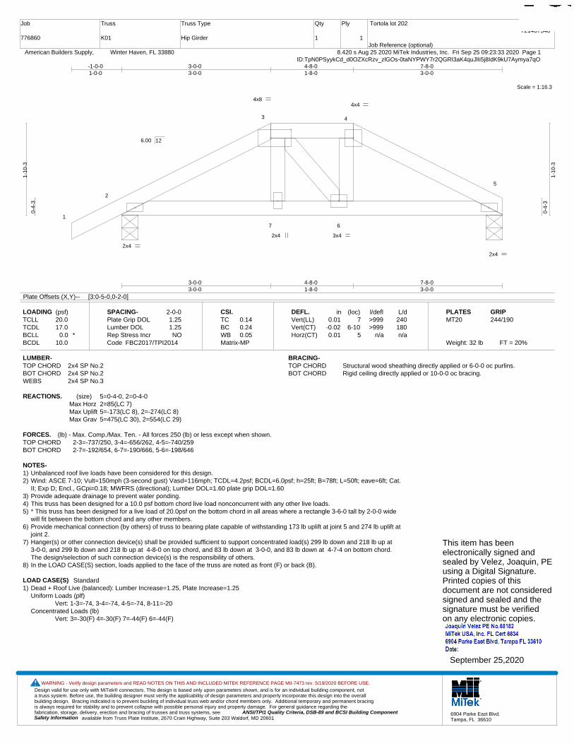
Design valid for use only with MiTek® connectors. This design is based only upon parameters shown, and is for an individual building component, not a truss system. Before use, the building designer must verify the applicability of design parameters and properly incorporate this design into the overall building design. Bracing indicated is to prevent buckling of individual truss web and/or chord members only. Additional temporary and permanent bracing is always required for stability and to prevent collapse with possible personal injury and property damage. For general guidance regarding the fabrication, storage, delivery, erection and bracing of trusses and truss systems, see ANSI/TPI1 Quality Criteria, DSB-89 and BCSI Building Component
available from Truss Plate Institute, 2670 Crain Highway, Suite 203 Waldorf, MD 20601Safety Information
WARNING - Verify design parameters and READ NOTES ON THIS AND INCLUDED MITEK REFERENCE PAGE MII-7473 rev. 5/19/2020 BEFORE USE.
6904 Parke East Blvd.Tampa, FL 36610
Job
776860
Truss
K01
Truss Type
Hip Girder
Qty
1
Ply
1
Tortola lot 202
Job Reference (optional)
T21407540
8.420 s Aug 25 2020 MiTek Industries, Inc. Fri Sep 25 09:23:33 2020 Page 1 American Builders Supply, Winter Haven, FL 33880ID:TpN0PSyykCd_d0OZXcRzv_zlGOs-0taNYPWY7r2QGRI3aK4quJlIi5j8IdK9kU7Aymya7qO
Scale = 1:16.3
1
2
3 4
5
7 6
4x8 4x4
2x4
2x4
2x4 3x4
3-0-03-0-0
4-8-01-8-0
7-8-03-0-0
-1-0-01-0-0
3-0-03-0-0
4-8-01-8-0
7-8-03-0-0
0-4-
3
1-10
-3
0-4-
3
1-10
-3
6.00 12
Plate Offsets (X,Y)-- [3:0-5-0,0-2-0]
LOADING (psf)TCLLTCDLBCLLBCDL
20.017.0
0.0 *10.0
SPACING-Plate Grip DOLLumber DOL Rep Stress IncrCode
2-0-01.251.25NO
FBC2017/TPI2014
CSI.TCBCWBMatrix-MP
0.140.240.05
DEFL.Vert(LL)Vert(CT)Horz(CT)
in0.01
-0.020.01
(loc)7
6-105
l/defl>999>999
n/a
L/d240180n/a
PLATESMT20
Weight: 32 lb FT = 20%
GRIP244/190
LUMBER-TOP CHORD 2x4 SP No.2BOT CHORD 2x4 SP No.2WEBS 2x4 SP No.3
BRACING-TOP CHORD Structural wood sheathing directly applied or 6-0-0 oc purlins.BOT CHORD Rigid ceiling directly applied or 10-0-0 oc bracing.
REACTIONS. (size) 5=0-4-0, 2=0-4-0Max Horz 2=85(LC 7)Max Uplift 5=-173(LC 8), 2=-274(LC 8)Max Grav 5=475(LC 30), 2=554(LC 29)
FORCES. (lb) - Max. Comp./Max. Ten. - All forces 250 (lb) or less except when shown.TOP CHORD 2-3=-737/250, 3-4=-656/262, 4-5=-740/259BOT CHORD 2-7=-192/654, 6-7=-190/666, 5-6=-198/646
NOTES-1) Unbalanced roof live loads have been considered for this design.2) Wind: ASCE 7-10; Vult=150mph (3-second gust) Vasd=116mph; TCDL=4.2psf; BCDL=6.0psf; h=25ft; B=78ft; L=50ft; eave=6ft; Cat.
II; Exp D; Encl., GCpi=0.18; MWFRS (directional); Lumber DOL=1.60 plate grip DOL=1.603) Provide adequate drainage to prevent water ponding.4) This truss has been designed for a 10.0 psf bottom chord live load nonconcurrent with any other live loads.5) * This truss has been designed for a live load of 20.0psf on the bottom chord in all areas where a rectangle 3-6-0 tall by 2-0-0 wide
will fit between the bottom chord and any other members.6) Provide mechanical connection (by others) of truss to bearing plate capable of withstanding 173 lb uplift at joint 5 and 274 lb uplift at
joint 2.7) Hanger(s) or other connection device(s) shall be provided sufficient to support concentrated load(s) 299 lb down and 218 lb up at
3-0-0, and 299 lb down and 218 lb up at 4-8-0 on top chord, and 83 lb down at 3-0-0, and 83 lb down at 4-7-4 on bottom chord. The design/selection of such connection device(s) is the responsibility of others.
8) In the LOAD CASE(S) section, loads applied to the face of the truss are noted as front (F) or back (B).
LOAD CASE(S) Standard1) Dead + Roof Live (balanced): Lumber Increase=1.25, Plate Increase=1.25
Uniform Loads (plf)Vert: 1-3=-74, 3-4=-74, 4-5=-74, 8-11=-20
Concentrated Loads (lb)Vert: 3=-30(F) 4=-30(F) 7=-44(F) 6=-44(F)
This item has beenelectronically signed andsealed by Velez, Joaquin, PEusing a Digital Signature.Printed copies of thisdocument are not consideredsigned and sealed and thesignature must be verified on any electronic copies.
September 25,2020
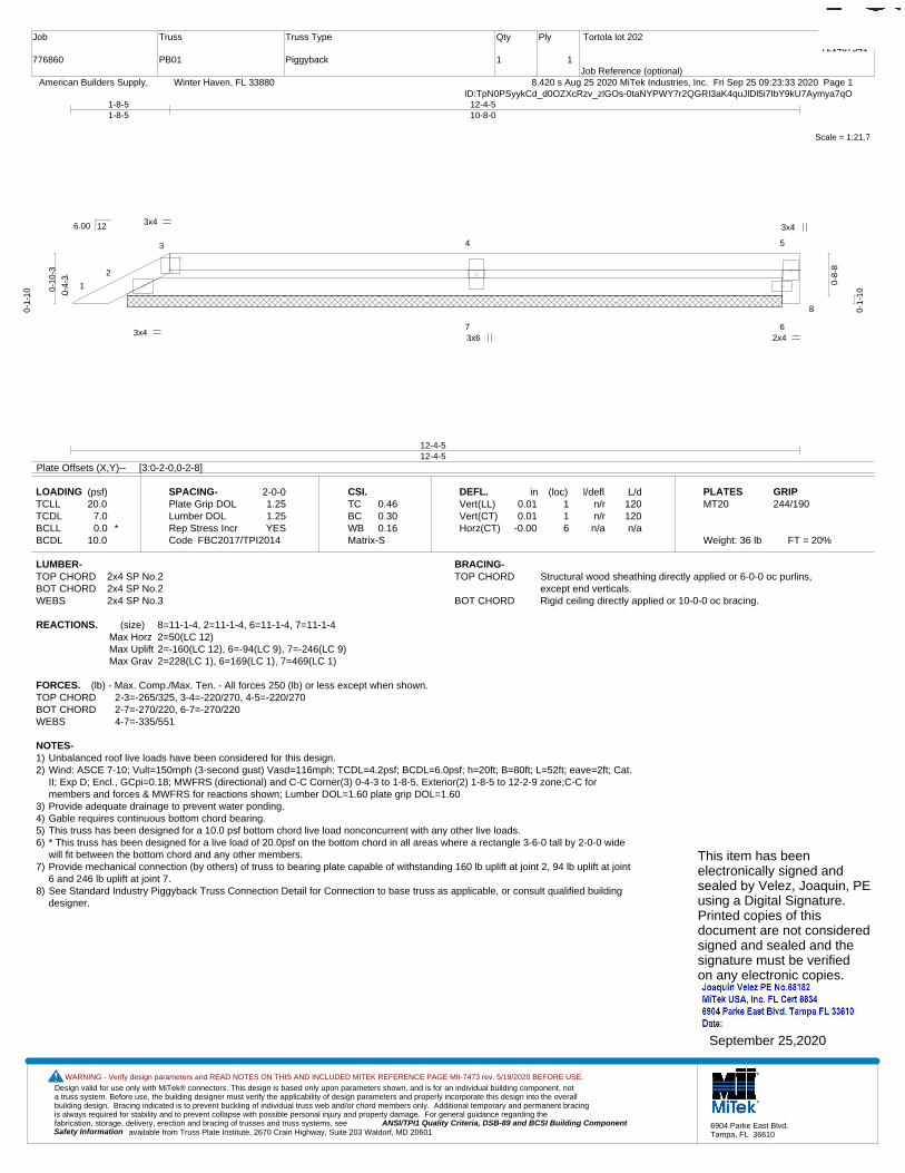
Design valid for use only with MiTek® connectors. This design is based only upon parameters shown, and is for an individual building component, not a truss system. Before use, the building designer must verify the applicability of design parameters and properly incorporate this design into the overall building design. Bracing indicated is to prevent buckling of individual truss web and/or chord members only. Additional temporary and permanent bracing is always required for stability and to prevent collapse with possible personal injury and property damage. For general guidance regarding the fabrication, storage, delivery, erection and bracing of trusses and truss systems, see ANSI/TPI1 Quality Criteria, DSB-89 and BCSI Building Component
available from Truss Plate Institute, 2670 Crain Highway, Suite 203 Waldorf, MD 20601Safety Information
WARNING - Verify design parameters and READ NOTES ON THIS AND INCLUDED MITEK REFERENCE PAGE MII-7473 rev. 5/19/2020 BEFORE USE.
6904 Parke East Blvd.Tampa, FL 36610
Job
776860
Truss
PB01
Truss Type
Piggyback
Qty
1
Ply
1
Tortola lot 202
Job Reference (optional)
T21407541
8.420 s Aug 25 2020 MiTek Industries, Inc. Fri Sep 25 09:23:33 2020 Page 1 American Builders Supply, Winter Haven, FL 33880ID:TpN0PSyykCd_d0OZXcRzv_zlGOs-0taNYPWY7r2QGRI3aK4quJlDl5i7IbY9kU7Aymya7qO
Scale = 1:21.7
1
2
3 4 5
7 6
8
3x4 3x4
3x4 2x4 3x6
12-4-512-4-5
1-8-51-8-5
12-4-510-8-0
0-4-
3
0-10
-3
0-1-
10
0-8-
8
0-1-
10
6.00 12
Plate Offsets (X,Y)-- [3:0-2-0,0-2-8]
LOADING (psf)TCLLTCDLBCLLBCDL
20.07.00.0 *
10.0
SPACING-Plate Grip DOLLumber DOL Rep Stress IncrCode
2-0-01.251.25YES
FBC2017/TPI2014
CSI.TCBCWBMatrix-S
0.460.300.16
DEFL.Vert(LL)Vert(CT)Horz(CT)
in0.010.01
-0.00
(loc)116
l/defln/rn/rn/a
L/d120120n/a
PLATESMT20
Weight: 36 lb FT = 20%
GRIP244/190
LUMBER-TOP CHORD 2x4 SP No.2BOT CHORD 2x4 SP No.2WEBS 2x4 SP No.3
BRACING-TOP CHORD Structural wood sheathing directly applied or 6-0-0 oc purlins,
except end verticals.BOT CHORD Rigid ceiling directly applied or 10-0-0 oc bracing.
REACTIONS. (size) 8=11-1-4, 2=11-1-4, 6=11-1-4, 7=11-1-4Max Horz 2=50(LC 12)Max Uplift 2=-160(LC 12), 6=-94(LC 9), 7=-246(LC 9)Max Grav 2=228(LC 1), 6=169(LC 1), 7=469(LC 1)
FORCES. (lb) - Max. Comp./Max. Ten. - All forces 250 (lb) or less except when shown.TOP CHORD 2-3=-265/325, 3-4=-220/270, 4-5=-220/270BOT CHORD 2-7=-270/220, 6-7=-270/220WEBS 4-7=-335/551
NOTES-1) Unbalanced roof live loads have been considered for this design.2) Wind: ASCE 7-10; Vult=150mph (3-second gust) Vasd=116mph; TCDL=4.2psf; BCDL=6.0psf; h=20ft; B=80ft; L=52ft; eave=2ft; Cat.
II; Exp D; Encl., GCpi=0.18; MWFRS (directional) and C-C Corner(3) 0-4-3 to 1-8-5, Exterior(2) 1-8-5 to 12-2-9 zone;C-C formembers and forces & MWFRS for reactions shown; Lumber DOL=1.60 plate grip DOL=1.60
3) Provide adequate drainage to prevent water ponding.4) Gable requires continuous bottom chord bearing. 5) This truss has been designed for a 10.0 psf bottom chord live load nonconcurrent with any other live loads.6) * This truss has been designed for a live load of 20.0psf on the bottom chord in all areas where a rectangle 3-6-0 tall by 2-0-0 wide
will fit between the bottom chord and any other members.7) Provide mechanical connection (by others) of truss to bearing plate capable of withstanding 160 lb uplift at joint 2, 94 lb uplift at joint
6 and 246 lb uplift at joint 7.8) See Standard Industry Piggyback Truss Connection Detail for Connection to base truss as applicable, or consult qualified building
designer.
This item has beenelectronically signed andsealed by Velez, Joaquin, PEusing a Digital Signature.Printed copies of thisdocument are not consideredsigned and sealed and thesignature must be verified on any electronic copies.
September 25,2020
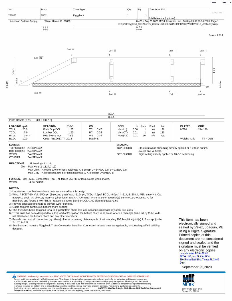
Design valid for use only with MiTek® connectors. This design is based only upon parameters shown, and is for an individual building component, not a truss system. Before use, the building designer must verify the applicability of design parameters and properly incorporate this design into the overall building design. Bracing indicated is to prevent buckling of individual truss web and/or chord members only. Additional temporary and permanent bracing is always required for stability and to prevent collapse with possible personal injury and property damage. For general guidance regarding the fabrication, storage, delivery, erection and bracing of trusses and truss systems, see ANSI/TPI1 Quality Criteria, DSB-89 and BCSI Building Component
available from Truss Plate Institute, 2670 Crain Highway, Suite 203 Waldorf, MD 20601Safety Information
WARNING - Verify design parameters and READ NOTES ON THIS AND INCLUDED MITEK REFERENCE PAGE MII-7473 rev. 5/19/2020 BEFORE USE.
6904 Parke East Blvd.Tampa, FL 36610
Job
776860
Truss
PB02
Truss Type
Piggyback
Qty
1
Ply
1
Tortola lot 202
Job Reference (optional)
T21407542
8.420 s Aug 25 2020 MiTek Industries, Inc. Fri Sep 25 09:23:34 2020 Page 1 American Builders Supply, Winter Haven, FL 33880ID:TpN0PSyykCd_d0OZXcRzv_zlGOs-U38lmlXBu8AHtbtF82b3QWIOMV3L12_Jz8tkUCya7qN
Scale = 1:21.7
1
2
3 4 5 6
9 8 7
10
3x4 3x4
4x4 4x4 2x4
2x4
2x4
2x4
12-4-512-4-5
3-8-53-8-5
12-4-58-8-0
0-4-
3
1-10
-3
0-1-
10
1-8-
8
0-1-
10
6.00 12
Plate Offsets (X,Y)-- [3:0-2-0,0-2-8]
LOADING (psf)TCLLTCDLBCLLBCDL
20.07.00.0 *
10.0
SPACING-Plate Grip DOLLumber DOL Rep Stress IncrCode
2-0-01.251.25YES
FBC2017/TPI2014
CSI.TCBCWBMatrix-S
0.470.240.15
DEFL.Vert(LL)Vert(CT)Horz(CT)
in0.000.010.01
(loc)11
10
l/defln/rn/rn/a
L/d120120n/a
PLATESMT20
Weight: 41 lb FT = 20%
GRIP244/190
LUMBER-TOP CHORD 2x4 SP No.2BOT CHORD 2x4 SP No.2WEBS 2x4 SP No.3OTHERS 2x4 SP No.3
BRACING-TOP CHORD Structural wood sheathing directly applied or 6-0-0 oc purlins,
except end verticals.BOT CHORD Rigid ceiling directly applied or 10-0-0 oc bracing.
REACTIONS. All bearings 11-1-4.(lb) - Max Horz 2=111(LC 12)
Max Uplift All uplift 100 lb or less at joint(s) 7, 8 except 2=-147(LC 12), 9=-221(LC 12)Max Grav All reactions 250 lb or less at joint(s) 2, 7, 8 except 9=394(LC 1)
FORCES. (lb) - Max. Comp./Max. Ten. - All forces 250 (lb) or less except when shown.WEBS 4-9=-270/511
NOTES-1) Unbalanced roof live loads have been considered for this design.2) Wind: ASCE 7-10; Vult=150mph (3-second gust) Vasd=116mph; TCDL=4.2psf; BCDL=6.0psf; h=21ft; B=80ft; L=52ft; eave=4ft; Cat.
II; Exp D; Encl., GCpi=0.18; MWFRS (directional) and C-C Corner(3) 0-4-3 to 3-8-5, Exterior(2) 3-8-5 to 12-2-9 zone;C-C formembers and forces & MWFRS for reactions shown; Lumber DOL=1.60 plate grip DOL=1.60
3) Provide adequate drainage to prevent water ponding.4) Gable requires continuous bottom chord bearing. 5) This truss has been designed for a 10.0 psf bottom chord live load nonconcurrent with any other live loads.6) * This truss has been designed for a live load of 20.0psf on the bottom chord in all areas where a rectangle 3-6-0 tall by 2-0-0 wide
will fit between the bottom chord and any other members.7) Provide mechanical connection (by others) of truss to bearing plate capable of withstanding 100 lb uplift at joint(s) 7, 8 except (jt=lb)
2=147, 9=221.8) See Standard Industry Piggyback Truss Connection Detail for Connection to base truss as applicable, or consult qualified building
designer.
This item has beenelectronically signed andsealed by Velez, Joaquin, PEusing a Digital Signature.Printed copies of thisdocument are not consideredsigned and sealed and thesignature must be verified on any electronic copies.
September 25,2020

Design valid for use only with MiTek® connectors. This design is based only upon parameters shown, and is for an individual building component, not a truss system. Before use, the building designer must verify the applicability of design parameters and properly incorporate this design into the overall building design. Bracing indicated is to prevent buckling of individual truss web and/or chord members only. Additional temporary and permanent bracing is always required for stability and to prevent collapse with possible personal injury and property damage. For general guidance regarding the fabrication, storage, delivery, erection and bracing of trusses and truss systems, see ANSI/TPI1 Quality Criteria, DSB-89 and BCSI Building Component
available from Truss Plate Institute, 2670 Crain Highway, Suite 203 Waldorf, MD 20601Safety Information
WARNING - Verify design parameters and READ NOTES ON THIS AND INCLUDED MITEK REFERENCE PAGE MII-7473 rev. 5/19/2020 BEFORE USE.
6904 Parke East Blvd.Tampa, FL 36610
Job
776860
Truss
PB03
Truss Type
Piggyback
Qty
1
Ply
1
Tortola lot 202
Job Reference (optional)
T21407543
8.420 s Aug 25 2020 MiTek Industries, Inc. Fri Sep 25 09:23:35 2020 Page 1 American Builders Supply, Winter Haven, FL 33880ID:TpN0PSyykCd_d0OZXcRzv_zlGOs-yGi7z5XpfSI8VlSRil6IzkrW0uNpmUISCocH0eya7qM
Scale = 1:21.5
1
2
3 4 5 6
9 8 7
10
3x4 2x4
4x4 2x4 2x4
3x6
2x4
2x4
12-4-512-4-5
5-8-55-8-5
12-4-56-8-0
0-4-
3
2-10
-3
0-1-
10
2-8-
8
0-1-
10
6.00 12
Plate Offsets (X,Y)-- [3:0-2-0,0-2-8]
LOADING (psf)TCLLTCDLBCLLBCDL
20.07.00.0 *
10.0
SPACING-Plate Grip DOLLumber DOL Rep Stress IncrCode
2-0-01.251.25YES
FBC2017/TPI2014
CSI.TCBCWBMatrix-S
0.670.350.21
DEFL.Vert(LL)Vert(CT)Horz(CT)
in-0.000.010.00
(loc)11
10
l/defln/rn/rn/a
L/d120120n/a
PLATESMT20
Weight: 46 lb FT = 20%
GRIP244/190
LUMBER-TOP CHORD 2x4 SP No.2BOT CHORD 2x4 SP No.2WEBS 2x4 SP No.3OTHERS 2x4 SP No.3
BRACING-TOP CHORD Structural wood sheathing directly applied or 6-0-0 oc purlins,
except end verticals.BOT CHORD Rigid ceiling directly applied or 6-0-0 oc bracing.
REACTIONS. All bearings 11-1-4.(lb) - Max Horz 2=173(LC 12)
Max Uplift All uplift 100 lb or less at joint(s) 7 except 2=-108(LC 12), 9=-261(LC 12), 8=-150(LC 8)Max Grav All reactions 250 lb or less at joint(s) 2, 7 except 9=422(LC 17), 8=254(LC 22)
FORCES. (lb) - Max. Comp./Max. Ten. - All forces 250 (lb) or less except when shown.WEBS 4-9=-293/709, 5-8=-197/254
NOTES-1) Unbalanced roof live loads have been considered for this design.2) Wind: ASCE 7-10; Vult=150mph (3-second gust) Vasd=116mph; TCDL=4.2psf; BCDL=6.0psf; h=21ft; B=80ft; L=52ft; eave=4ft; Cat.
II; Exp D; Encl., GCpi=0.18; MWFRS (directional) and C-C Corner(3) 0-4-3 to 5-8-5, Exterior(2) 5-8-5 to 12-2-9 zone;C-C formembers and forces & MWFRS for reactions shown; Lumber DOL=1.60 plate grip DOL=1.60
3) Provide adequate drainage to prevent water ponding.4) Gable requires continuous bottom chord bearing. 5) This truss has been designed for a 10.0 psf bottom chord live load nonconcurrent with any other live loads.6) * This truss has been designed for a live load of 20.0psf on the bottom chord in all areas where a rectangle 3-6-0 tall by 2-0-0 wide
will fit between the bottom chord and any other members.7) Provide mechanical connection (by others) of truss to bearing plate capable of withstanding 100 lb uplift at joint(s) 7 except (jt=lb)
2=108, 9=261, 8=150.8) See Standard Industry Piggyback Truss Connection Detail for Connection to base truss as applicable, or consult qualified building
designer.
This item has beenelectronically signed andsealed by Velez, Joaquin, PEusing a Digital Signature.Printed copies of thisdocument are not consideredsigned and sealed and thesignature must be verified on any electronic copies.
September 25,2020
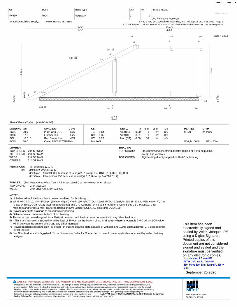
Design valid for use only with MiTek® connectors. This design is based only upon parameters shown, and is for an individual building component, not a truss system. Before use, the building designer must verify the applicability of design parameters and properly incorporate this design into the overall building design. Bracing indicated is to prevent buckling of individual truss web and/or chord members only. Additional temporary and permanent bracing is always required for stability and to prevent collapse with possible personal injury and property damage. For general guidance regarding the fabrication, storage, delivery, erection and bracing of trusses and truss systems, see ANSI/TPI1 Quality Criteria, DSB-89 and BCSI Building Component
available from Truss Plate Institute, 2670 Crain Highway, Suite 203 Waldorf, MD 20601Safety Information
WARNING - Verify design parameters and READ NOTES ON THIS AND INCLUDED MITEK REFERENCE PAGE MII-7473 rev. 5/19/2020 BEFORE USE.
6904 Parke East Blvd.Tampa, FL 36610
Job
776860
Truss
PB04
Truss Type
Piggyback
Qty
1
Ply
1
Tortola lot 202
Job Reference (optional)
T21407544
8.420 s Aug 25 2020 MiTek Industries, Inc. Fri Sep 25 09:23:35 2020 Page 1 American Builders Supply, Winter Haven, FL 33880ID:TpN0PSyykCd_d0OZXcRzv_zlGOs-yGi7z5XpfSI8VlSRil6IzkrWNuNxmUzSCocH0eya7qM
Scale = 1:23.3
1
2
3
4 5 6
9 8 7
11
10
3x4 2x4
4x4 2x4 2x4
2x4
2x4
2x4
12-4-512-4-5
7-8-57-8-5
12-4-54-8-0
0-4-
3
3-10
-3
0-1-
10
3-8-
8
0-1-
10
6.00 12
Plate Offsets (X,Y)-- [4:0-2-0,0-2-8]
LOADING (psf)TCLLTCDLBCLLBCDL
20.07.00.0 *
10.0
SPACING-Plate Grip DOLLumber DOL Rep Stress IncrCode
2-0-01.251.25YES
FBC2017/TPI2014
CSI.TCBCWBMatrix-S
0.640.350.23
DEFL.Vert(LL)Vert(CT)Horz(CT)
in-0.000.01
-0.00
(loc)11
10
l/defln/rn/rn/a
L/d120120n/a
PLATESMT20
Weight: 50 lb FT = 20%
GRIP244/190
LUMBER-TOP CHORD 2x4 SP No.2BOT CHORD 2x4 SP No.2WEBS 2x4 SP No.3OTHERS 2x4 SP No.3
BRACING-TOP CHORD Structural wood sheathing directly applied or 6-0-0 oc purlins,
except end verticals.BOT CHORD Rigid ceiling directly applied or 10-0-0 oc bracing.
REACTIONS. All bearings 11-1-4.(lb) - Max Horz 2=235(LC 12)
Max Uplift All uplift 100 lb or less at joint(s) 2, 7 except 9=-301(LC 12), 8=-130(LC 8)Max Grav All reactions 250 lb or less at joint(s) 2, 7, 8 except 9=471(LC 17)
FORCES. (lb) - Max. Comp./Max. Ten. - All forces 250 (lb) or less except when shown.TOP CHORD 2-3=-322/108WEBS 3-9=-343/780, 5-8=-173/255
NOTES-1) Unbalanced roof live loads have been considered for this design.2) Wind: ASCE 7-10; Vult=150mph (3-second gust) Vasd=116mph; TCDL=4.2psf; BCDL=6.0psf; h=22ft; B=80ft; L=52ft; eave=3ft; Cat.
II; Exp D; Encl., GCpi=0.18; MWFRS (directional) and C-C Corner(3) 0-4-3 to 5-6-9, Exterior(2) 5-6-9 to 12-2-9 zone;C-C formembers and forces & MWFRS for reactions shown; Lumber DOL=1.60 plate grip DOL=1.60
3) Provide adequate drainage to prevent water ponding.4) Gable requires continuous bottom chord bearing. 5) This truss has been designed for a 10.0 psf bottom chord live load nonconcurrent with any other live loads.6) * This truss has been designed for a live load of 20.0psf on the bottom chord in all areas where a rectangle 3-6-0 tall by 2-0-0 wide
will fit between the bottom chord and any other members.7) Provide mechanical connection (by others) of truss to bearing plate capable of withstanding 100 lb uplift at joint(s) 2, 7 except (jt=lb)
9=301, 8=130.8) See Standard Industry Piggyback Truss Connection Detail for Connection to base truss as applicable, or consult qualified building
designer.
This item has beenelectronically signed andsealed by Velez, Joaquin, PEusing a Digital Signature.Printed copies of thisdocument are not consideredsigned and sealed and thesignature must be verified on any electronic copies.
September 25,2020
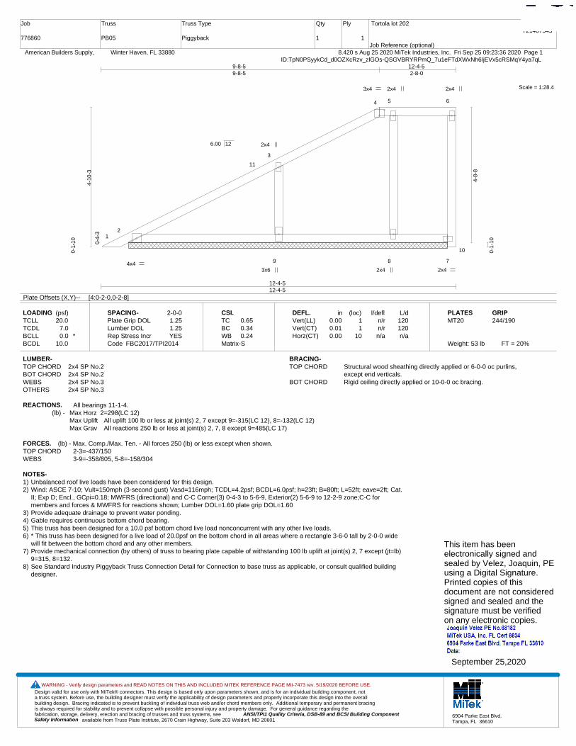
Design valid for use only with MiTek® connectors. This design is based only upon parameters shown, and is for an individual building component, not a truss system. Before use, the building designer must verify the applicability of design parameters and properly incorporate this design into the overall building design. Bracing indicated is to prevent buckling of individual truss web and/or chord members only. Additional temporary and permanent bracing is always required for stability and to prevent collapse with possible personal injury and property damage. For general guidance regarding the fabrication, storage, delivery, erection and bracing of trusses and truss systems, see ANSI/TPI1 Quality Criteria, DSB-89 and BCSI Building Component
available from Truss Plate Institute, 2670 Crain Highway, Suite 203 Waldorf, MD 20601Safety Information
WARNING - Verify design parameters and READ NOTES ON THIS AND INCLUDED MITEK REFERENCE PAGE MII-7473 rev. 5/19/2020 BEFORE USE.
6904 Parke East Blvd.Tampa, FL 36610
Job
776860
Truss
PB05
Truss Type
Piggyback
Qty
1
Ply
1
Tortola lot 202
Job Reference (optional)
T21407545
8.420 s Aug 25 2020 MiTek Industries, Inc. Fri Sep 25 09:23:36 2020 Page 1 American Builders Supply, Winter Haven, FL 33880ID:TpN0PSyykCd_d0OZXcRzv_zlGOs-QSGVBRYRPmQ_7u1eFTdXWxNh6IjEVx5cRSMqY4ya7qL
Scale = 1:28.4
12
3
4 5 6
9 8 7
11
10
3x4 2x4
4x4 2x4 3x6
2x4
2x4
2x4
12-4-512-4-5
9-8-59-8-5
12-4-52-8-0
0-4-
3
4-10
-3
0-1-
10
4-8-
8
0-1-
10
6.00 12
Plate Offsets (X,Y)-- [4:0-2-0,0-2-8]
LOADING (psf)TCLLTCDLBCLLBCDL
20.07.00.0 *
10.0
SPACING-Plate Grip DOLLumber DOL Rep Stress IncrCode
2-0-01.251.25YES
FBC2017/TPI2014
CSI.TCBCWBMatrix-S
0.650.340.24
DEFL.Vert(LL)Vert(CT)Horz(CT)
in0.000.010.00
(loc)11
10
l/defln/rn/rn/a
L/d120120n/a
PLATESMT20
Weight: 53 lb FT = 20%
GRIP244/190
LUMBER-TOP CHORD 2x4 SP No.2BOT CHORD 2x4 SP No.2WEBS 2x4 SP No.3OTHERS 2x4 SP No.3
BRACING-TOP CHORD Structural wood sheathing directly applied or 6-0-0 oc purlins,
except end verticals.BOT CHORD Rigid ceiling directly applied or 10-0-0 oc bracing.
REACTIONS. All bearings 11-1-4.(lb) - Max Horz 2=298(LC 12)
Max Uplift All uplift 100 lb or less at joint(s) 2, 7 except 9=-315(LC 12), 8=-132(LC 12)Max Grav All reactions 250 lb or less at joint(s) 2, 7, 8 except 9=485(LC 17)
FORCES. (lb) - Max. Comp./Max. Ten. - All forces 250 (lb) or less except when shown.TOP CHORD 2-3=-437/150WEBS 3-9=-358/805, 5-8=-158/304
NOTES-1) Unbalanced roof live loads have been considered for this design.2) Wind: ASCE 7-10; Vult=150mph (3-second gust) Vasd=116mph; TCDL=4.2psf; BCDL=6.0psf; h=23ft; B=80ft; L=52ft; eave=2ft; Cat.
II; Exp D; Encl., GCpi=0.18; MWFRS (directional) and C-C Corner(3) 0-4-3 to 5-6-9, Exterior(2) 5-6-9 to 12-2-9 zone;C-C formembers and forces & MWFRS for reactions shown; Lumber DOL=1.60 plate grip DOL=1.60
3) Provide adequate drainage to prevent water ponding.4) Gable requires continuous bottom chord bearing. 5) This truss has been designed for a 10.0 psf bottom chord live load nonconcurrent with any other live loads.6) * This truss has been designed for a live load of 20.0psf on the bottom chord in all areas where a rectangle 3-6-0 tall by 2-0-0 wide
will fit between the bottom chord and any other members.7) Provide mechanical connection (by others) of truss to bearing plate capable of withstanding 100 lb uplift at joint(s) 2, 7 except (jt=lb)
9=315, 8=132.8) See Standard Industry Piggyback Truss Connection Detail for Connection to base truss as applicable, or consult qualified building
designer.
This item has beenelectronically signed andsealed by Velez, Joaquin, PEusing a Digital Signature.Printed copies of thisdocument are not consideredsigned and sealed and thesignature must be verified on any electronic copies.
September 25,2020
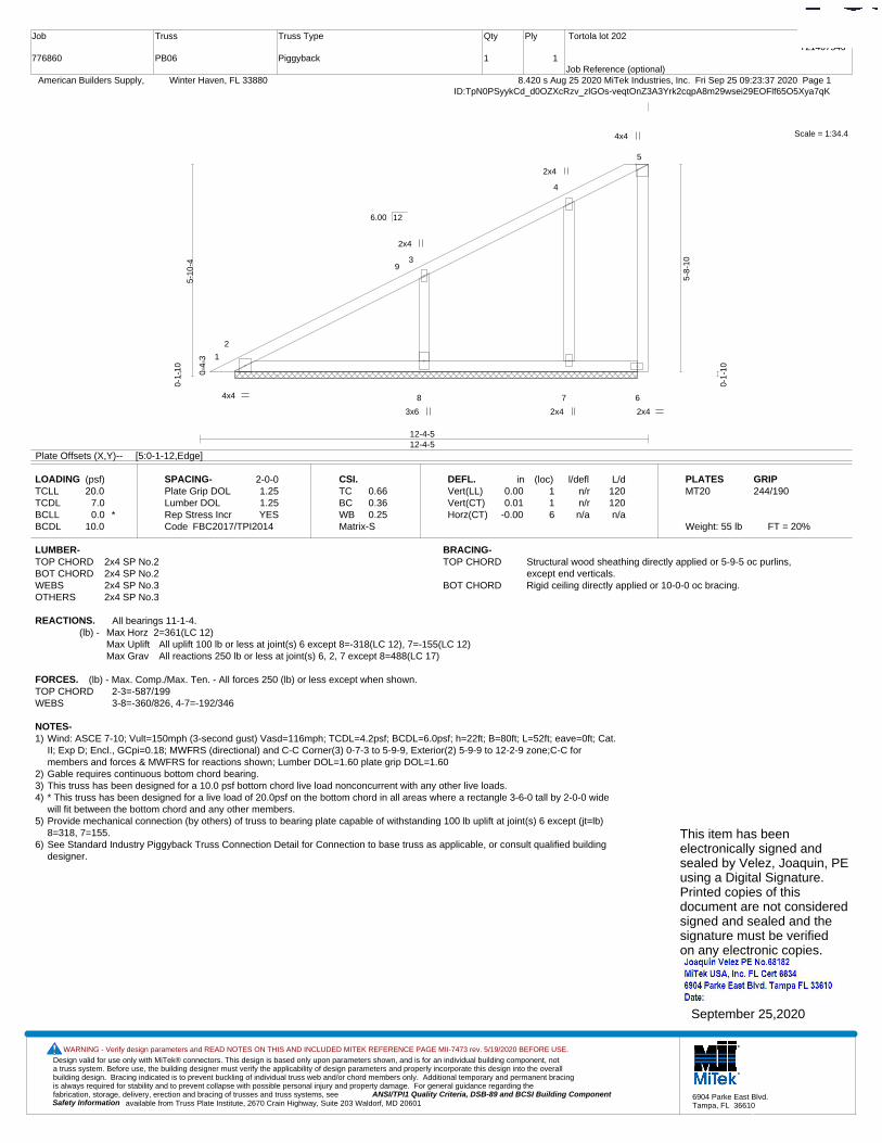
Design valid for use only with MiTek® connectors. This design is based only upon parameters shown, and is for an individual building component, not a truss system. Before use, the building designer must verify the applicability of design parameters and properly incorporate this design into the overall building design. Bracing indicated is to prevent buckling of individual truss web and/or chord members only. Additional temporary and permanent bracing is always required for stability and to prevent collapse with possible personal injury and property damage. For general guidance regarding the fabrication, storage, delivery, erection and bracing of trusses and truss systems, see ANSI/TPI1 Quality Criteria, DSB-89 and BCSI Building Component
available from Truss Plate Institute, 2670 Crain Highway, Suite 203 Waldorf, MD 20601Safety Information
WARNING - Verify design parameters and READ NOTES ON THIS AND INCLUDED MITEK REFERENCE PAGE MII-7473 rev. 5/19/2020 BEFORE USE.
6904 Parke East Blvd.Tampa, FL 36610
Job
776860
Truss
PB06
Truss Type
Piggyback
Qty
1
Ply
1
Tortola lot 202
Job Reference (optional)
T21407546
8.420 s Aug 25 2020 MiTek Industries, Inc. Fri Sep 25 09:23:37 2020 Page 1 American Builders Supply, Winter Haven, FL 33880ID:TpN0PSyykCd_d0OZXcRzv_zlGOs-veqtOnZ3A3Yrk2cqpA8m29wsei29EOFlf65O5Xya7qK
Scale = 1:34.4
1
2
3
4
5
8 7 6
9
4x4
2x4
4x4
3x6
2x4
2x4
2x4
12-4-512-4-5
0-4-
3
5-10
-4
0-1-
10
5-8-
10
0-1-
10
6.00 12
Plate Offsets (X,Y)-- [5:0-1-12,Edge]
LOADING (psf)TCLLTCDLBCLLBCDL
20.07.00.0 *
10.0
SPACING-Plate Grip DOLLumber DOL Rep Stress IncrCode
2-0-01.251.25YES
FBC2017/TPI2014
CSI.TCBCWBMatrix-S
0.660.360.25
DEFL.Vert(LL)Vert(CT)Horz(CT)
in0.000.01
-0.00
(loc)116
l/defln/rn/rn/a
L/d120120n/a
PLATESMT20
Weight: 55 lb FT = 20%
GRIP244/190
LUMBER-TOP CHORD 2x4 SP No.2BOT CHORD 2x4 SP No.2WEBS 2x4 SP No.3OTHERS 2x4 SP No.3
BRACING-TOP CHORD Structural wood sheathing directly applied or 5-9-5 oc purlins,
except end verticals.BOT CHORD Rigid ceiling directly applied or 10-0-0 oc bracing.
REACTIONS. All bearings 11-1-4.(lb) - Max Horz 2=361(LC 12)
Max Uplift All uplift 100 lb or less at joint(s) 6 except 8=-318(LC 12), 7=-155(LC 12)Max Grav All reactions 250 lb or less at joint(s) 6, 2, 7 except 8=488(LC 17)
FORCES. (lb) - Max. Comp./Max. Ten. - All forces 250 (lb) or less except when shown.TOP CHORD 2-3=-587/199WEBS 3-8=-360/826, 4-7=-192/346
NOTES-1) Wind: ASCE 7-10; Vult=150mph (3-second gust) Vasd=116mph; TCDL=4.2psf; BCDL=6.0psf; h=22ft; B=80ft; L=52ft; eave=0ft; Cat.
II; Exp D; Encl., GCpi=0.18; MWFRS (directional) and C-C Corner(3) 0-7-3 to 5-9-9, Exterior(2) 5-9-9 to 12-2-9 zone;C-C formembers and forces & MWFRS for reactions shown; Lumber DOL=1.60 plate grip DOL=1.60
2) Gable requires continuous bottom chord bearing. 3) This truss has been designed for a 10.0 psf bottom chord live load nonconcurrent with any other live loads.4) * This truss has been designed for a live load of 20.0psf on the bottom chord in all areas where a rectangle 3-6-0 tall by 2-0-0 wide
will fit between the bottom chord and any other members.5) Provide mechanical connection (by others) of truss to bearing plate capable of withstanding 100 lb uplift at joint(s) 6 except (jt=lb)
8=318, 7=155.6) See Standard Industry Piggyback Truss Connection Detail for Connection to base truss as applicable, or consult qualified building
designer.
This item has beenelectronically signed andsealed by Velez, Joaquin, PEusing a Digital Signature.Printed copies of thisdocument are not consideredsigned and sealed and thesignature must be verified on any electronic copies.
September 25,2020
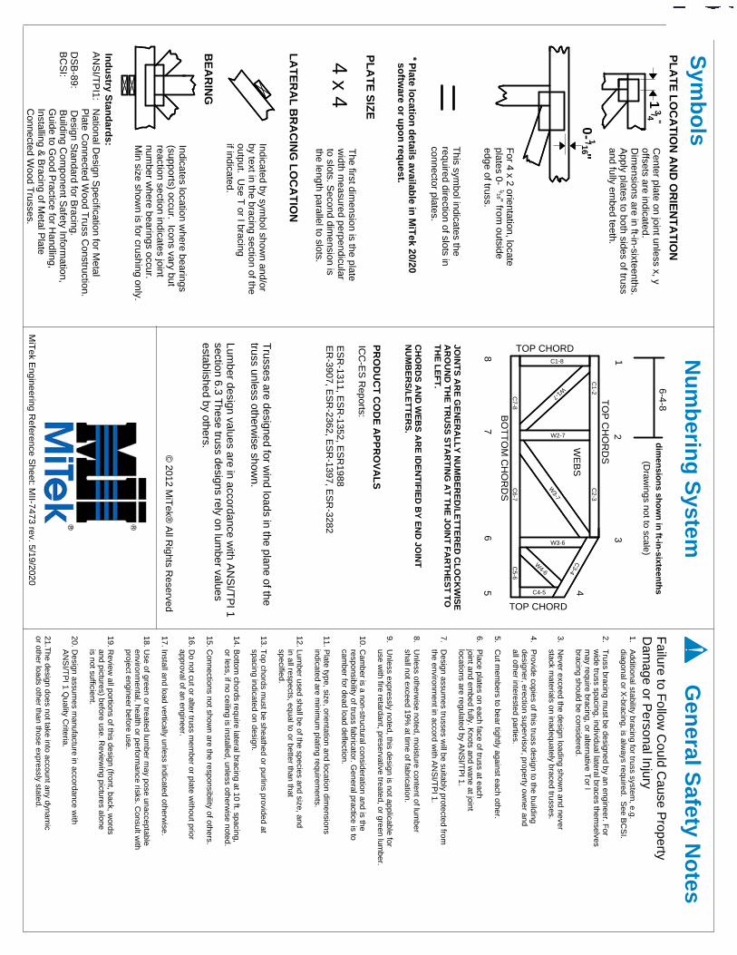
PR
OD
UC
T C
OD
E A
PP
RO
VA
LS
LA
TE
RA
L B
RA
CIN
G L
OC
AT
ION
Indicates location where bearings
(supports) occur. Icons vary butreaction section indicates jointnum
ber where bearings occur.
Min size show
n is for crushing only.
Indicated by symbol show
n and/orby text in the bracing section of theoutput. U
se T or I bracing
if indicated.
The first dim
ension is the plate w
idth measured perpendicular
to slots. Second dim
ension isthe length parallel to slots.
Center plate on joint unless x, y
offsets are indicated.D
imensions are in ft-in-sixteenths.
Apply plates to both sides of truss
and fully embed teeth.
1. Additional stability bracing for truss system
, e.g. diagonal or X
-bracing, is always required. S
ee BC
SI.
2. Truss bracing m
ust be designed by an engineer. For
wide truss spacing, individual lateral braces them
selves m
ay require bracing, or alternative Tor I
bracing should be considered.
3. Never exceed the design loading show
n and never stack m
aterials on inadequately braced trusses.
4. Provide copies of this truss design to the building
designer, erection supervisor, property owner and
all other interested parties.
5. Cut m
embers to bear tightly against each other.
6. Place plates on each face of truss at each
joint and embed fully. K
nots and wane at joint
locations are regulated by AN
SI/T
PI 1.
7. Design assum
es trusses will be suitably protected from
the environment in accord w
ith AN
SI/T
PI 1.
8. Unless otherw
ise noted, moisture content of lum
ber shall not exceed 19%
at time of fabrication.
9. Unless expressly noted, this design is not applicable for
use with fire retardant, preservative treated, or green lum
ber.
10. Cam
ber is a non-structural consideration and is the responsibility of truss fabricator. G
eneral practice is to cam
ber for dead load deflection.
11. Plate type, size, orientation and location dim
ensions indicated are m
inimum
plating requirements.
12. Lumber used shall be of the species and size, and
in all respects, equal to or better than that specified.
13. Top chords m
ust be sheathed or purlins provided at spacing indicated on design.
14. Bottom
chords require lateral bracing at 10 ft. spacing, or less, if no ceiling is installed, unless otherw
ise noted.
15. Connections not show
n are the responsibility of others.
16. Do not cut or alter truss m
ember or plate w
ithout prior approval of an engineer.
17. Install and load vertically unless indicated otherwise.
18. Use of green or treated lum
ber may pose unacceptable
environmental, health or perform
ance risks. Consult w
ith project engineer before use.
19. Review
all portions of this design (front, back, words
and pictures) before use. Review
ing pictures alone is not sufficient.
20. Design assum
es manufacture in accordance w
ith A
NS
I/TP
I 1 Quality C
riteria.
21.The design does not take into account any dynam
ic or other loads other than those expressly stated.
Failure to F
ollow C
ould Cause P
ropertyD
amage or P
ersonal Injury
(Draw
ings not to scale)
© 2012 M
iTek®
All R
ights Reserved
MiT
ek Engineering R
eference Sheet: M
II-7473 rev. 5/19/2020
edge of truss. from outside
" 16/ 1
-0
ICC
-ES
Reports:
ES
R-1311, E
SR
-1352, ES
R1988
ER
-3907, ES
R-2362, E
SR
-1397, ES
R-3282
JOIN
TS
AR
E G
EN
ER
AL
LY
NU
MB
ER
ED
/LE
TT
ER
ED
CL
OC
KW
ISE
AR
OU
ND
TH
E T
RU
SS
ST
AR
TIN
G A
T T
HE
JOIN
T F
AR
TH
ES
T T
OT
HE
LE
FT
.
CH
OR
DS
AN
D W
EB
S A
RE
IDE
NT
IFIE
D B
Y E
ND
JOIN
TN
UM
BE
RS
/LE
TT
ER
S.
W4-6
W3-6
W3-7
W2-7
W1-7
C1-8
C5-6
C6-7
C7-8
C4-5
C3-4
C2-3
C1-2
TOP CHORD
TOP CHORD87
65 4
32
1
BO
TT
OM
CH
OR
DS
TO
P C
HO
RD
S
BE
AR
ING
4 x 4
PL
AT
E S
IZE
This sym
bol indicates the required direction of slots inconnector plates.
"16
/ 1
For 4 x 2 orientation, locate
plates 0-
1"4 / 3
PL
AT
E L
OC
AT
ION
AN
D O
RIE
NT
AT
ION
Sym
bo
lsN
um
berin
g S
ystemG
eneral S
afety No
tes
*P
late locatio
n d
etails available in
MiT
ek 20/20so
ftware o
r up
on
requ
est.
Ind
ustry S
tand
ards:
AN
SI/T
PI1: N
ational Design S
pecification for Metal
Plate C
onnected Wood T
russ Construction.
DS
B-89: D
esign Standard for B
racing.B
CS
I: Building C
omponent S
afety Information,
Guide to G
ood Practice for H
andling, Installing &
Bracing of M
etal Plate
Connected W
ood Trusses.
6-4-8
WE
BS
Trusses are designed for w
ind loads in the plane of the truss unless otherw
ise shown.
Lumber design values are in accordance w
ith AN
SI/T
PI 1
section 6.3 These truss designs rely on lum
ber values established by others. d
imen
sion
s sho
wn
in ft-in
-sixteenth
s