Embed Size (px)
Citation preview
8/22/08 (Effective 9/1/08) 780 CMR - Seventh Edition 379
780 CMR 16.00STRUCTURAL DESIGN
780 CMR 16.00 is unique to Massachusetts
780 CMR 1601.0 GENERAL
1601.1 Scope. Provisions of 780 CMR 16.00 shallgovern the structural design of buildings, structuresand portions thereof regulated by 780 CMR.
1601.2 Massachusetts Building Code for One-and Two Family Dwellings. Where structuraldesign for buildings covered by the MassachusettsBuilding Code for One- and Two Family Dwellingsis performed by a registered design professional(RDP), said RDP may follow the structural designprovisions of the Massachusetts Basic Building Codein lieu of those in the Building Code for One- andTwo Family Dwellings, and shall follow the BasicBuilding Code for the structural design ofcomponents and systems not addressed in theBuilding Code for One- and Two Family Dwellings.
780 CMR 1602.0 DEFINITIONS
AND NOTATIONS
1602.1 Definitions. The following words and termsshall, for the purposes of 780 CMR 16.00, have themeanings shown in 780 CMR 1602.0. Fordefinitions not contained in 780 CMR 1602.0, seeappropriate sections of ASCE 7.
ALLOWABLE STRESS DESIGN. A method ofproportioning structural members, such thatelastically computed stresses produced in themembers by nominal loads do not exceed specifiedallowable stresses (also called working stressdesign).
BALCONY. A floor projecting from and supportedby a structure without additional independentsupports.
DEAD LOADS. The weight of materials ofconstruction incorporated into the building,including but not limited to walls, floors, roofs,ceilings, stairways, built-in partitions, finishes, clad-ding, and other similarly incorporated architecturaland structural items, and fixed service equipment,including the weight of cranes. All dead loads areconsidered permanent loads.
DECK. An exterior floor supported on at least twoopposing sides by an adjacent structure, and/or posts,piers or other independent supports.
DESIGN STRENGTH. The product of thenominal strength and a resistance factor (or strengthreduction factor).
DURATION OF LOAD. The period of continuousapplication of a given load, or the aggregate ofperiods of intermittent applications of the same load.
EQUIPMENT SUPPORT. Those structuralmembers or assemblies of members or manufacturedelements, including braces, frames, lugs, snuggers,hangers or saddles, that transmit gravity load andoperating load between the equipment and thestructure.
ESSENTIAL FACILITIES. Buildings and otherstructures that are intended to remain operational inthe event of extreme environmental loading fromflood, wind, snow or earthquakes.
FACTORED LOAD. The product of a nominalload and a load factor.
FLEXIBLE EQUIPMENT CONNECTIONS.Those connections between equipment componentsthat permit rotational and/or translational movementwithout degradation of performance.
GUARD. See 780 CMR 1002.1.
IMPACT LOAD. The load resulting from movingmachinery, elevators, craneways, vehicles, and othersimilar forces and kinetic loads, pressure andpossible surcharge from fixed or moving loads.
JOINT. A portion of a column bounded by thehighest and lowest surfaces of the other membersframing into it.
LATERAL FORCE-RESISTING SYSTEM. That part of the structural system that is consideredin the design to provide resistance to the wind andseismic forces prescribed in 780 CMR.
LIMIT STATE. A condition beyond which astructure or member becomes unfit for service and isjudged to be no longer useful for its intendedfunction (serviceability limit state) or to be unsafe(strength limit state).
LIVE LOADS. Those loads produced by the useand occupancy of the building or other structure anddo not include construction or environmental loadssuch as wind load, snow load, rain load, earthquakeload, flood load or dead load.
LIVE LOADS (ROOF). Those loads produced (1)during maintenance by workers, equipment andmaterials; and (2) during the life of the structure bymovable objects such as planters and by people.
LOAD AND RESISTANCE FACTOR DESIGN(LRFD). A method of proportioning structuralmembers and their connections using load andresistance factors such that no applicable limit stateis reached when the structure is subjected toappropriate load combinations. (Also called“strength design”).
780 CMR: STATE BOARD OF BUILDING REGULATIONS AND STANDARDS
THE MASSACHUSETTS STATE BUILDING CODE
380 780 CMR - Seventh Edition 8/22/08 (Effective 9/1/08)
LOAD FACTOR. A factor that accounts fordeviations of the actual load from the nominal load,for uncertainties in the analysis that transforms theload into a load effect, and for the probability thatmore than one extreme load will occursimultaneously.
LOADS. Forces or other actions that result from theweight of building materials, occupants and theirpossessions, environmental effects, differentialmovement, and restrained dimensional changes.Permanent loads are those loads in which variationsover time are rare or of small magnitude, such asdead loads. All other loads are variable loads (seealso “Nominal loads”).
LOADS EFFECTS. Forces and deformationsproduced in structural members by the applied loads.
NOMINAL LOADS. The magnitudes of the loadsspecified in 780 CMR 16.00 (dead, live, soil, wind,snow, rain, flood and earthquake).
NOTATIONS:D = Dead load.E = Combined effect of horizontal and verticalearthquake- induced forces.F = Load due to fluids.
aF = Flood load.H = Load due to lateral pressure of soil and waterin soil.L = Live load, except roof live load, includingany permitted live load reduction.
rL = Roof live load including any permitted liveload reduction.R = Rain load.S = Snow load.
T = Self-straining force arising from contractionor expansion resulting from temperature change,shrinkage, moisture change, creep in componentmaterials, movement due to differentialsettlement, or combinations thereof.W = Load due to wind pressure.
P-DELTA EFFECT. The second order effect onshears, axial forces and moments of frame membersinduced by gravity loads on a laterally displacedbuilding frame.
PANEL (PART OF A STRUCTURE). Thesection of a floor, wall or roof comprised betweenthe supporting frame of two adjacent rows ofcolumns and girders or column bands of floor or roofconstruction.
RESISTANCE FACTOR. A factor that accountsfor deviations of the actual strength from thenominal strength and the manner and consequencesof failure (also called strength reduction factor).
SHALLOW ANCHORS. Shallow anchors arethose with embedment length-to-diameter ratios ofless than 8.
SHEAR PANEL. A floor, roof or wall componentsheathed to act as a shear wall or diaphragm.
SHEAR WALL. A wall designed to resist lateralforces parallel to the plane of the wall.
STRENGTH, NOMINAL. The capacity of astructure or member to resist the effects of loads, asdetermined by computations using specified materialstrengths and dimensions and formulas derived fromaccepted principles of structural mechanics or byfield tests or laboratory tests of scaled models,allowing for modeling effects and differencesbetween laboratory and field conditions.
STRENGTH, REQUIRED. Strength of a member,cross section or connection required to resistfactored loads or related internal moments and forcesin such combinations as stipulated by theseprovisions.
STRENGTH DESIGN. A method of proportioningstructural members such that the computed forcesproduced in the members by factored loads do notexceed the member design strength (also called loadand resistance factor design).
WALL, LOAD BEARING. Any wall meetingeither of the following classifications:
1. Any metal or wood stud wall that supportsmore than 100 pounds per linear foot (1459 N/m)of vertical load in addition to its own weight.2. Any masonry or concrete wall that supportsmore than 200 pounds per linear foot (2919 N/m)of vertical load in addition to its own weight.
WALL, NONLOAD BEARING. Any wall that isnot a load-bearing wall.
780 CMR 1603.0 CONSTRUCTION
DOCUMENTS
1603.1 General. Construction documents shallshow the size, section and relative locations ofstructural members with floor levels, column centersand offsets fully dimensioned. The design loads andother information pertinent to the structural designrequired by 780 CMR 1603.1.1 through 1603.1.8shall be clearly indicated on the constructiondocuments for parts of the building or structure.
1603.1.1 Floor Live Load. The uniformlydistributed, concentrated, and impact floor liveloads used in the design and where they areapplied shall be indicated. Also, whether live loadreduction has been applied. shall be indicated.
1603.1.2 Roof Live Load. The roof live loadused in the design shall be indicated (780 CMR1607.11).
1603.1.3 Roof Snow Load. The ground snow
g fload, p , and the flat-roof snow load, p , and, if
sapplicable, the sloped roof snow load, p , shall beindicated.
780 CMR: STATE BOARD OF BUILDING REGULATIONS AND STANDARDS
STRUCTURAL DESIGN
8/22/08 (Effective 9/1/08) 780 CMR - Seventh Edition 381
1603.1.4 Wind Load. The following informationrelated to wind loads shall be shown, regardless ofwhether wind loads govern the design of thelateral-force resisting system of the building:
1. Basic wind speed (three-second gust), milesper hour (km/hr).
W2. Wind importance factor, I , and buildingcategory.3. Wind exposure. If more than one windexposure is utilized, the wind exposures andapplicable wind directions shall be indicated.
1603.1.5 Earthquake Design Data. Thefollowing information related to seismic loadsshall be shown, regardless of whether seismicloads govern the lateral design of the building:
E1. Seismic importance factor, I , and seismicuse group.
S2. Mapped spectral response accelerations S
1and S .3. Site class.
DS D14. Spectral response coefficients S and S .5. Seismic design category.6. Basic seismic-force-resisting system(s).7. Design base shear.
S8. Seismic response coefficient(s), C .9. Response modification factor(s), R.10. Analysis procedure used.
Where the information along different horizontalaxes of the building is different, the informationfor both orthogonal axes shall be show.
1603.1.6 Flood Load. For buildings located inflood-hazard areas, the design flood elevation andwhether or not the construction is subject to high-velocity wave action shall be indicated. Thefollowing information, referenced to the datum onthe community’s flood insurance rate map(FIRM), shall be shown, regardless of whetherflood loads govern the design of the building:
1. In flood-hazard areas not subject to high-velocity wave action, the elevation of proposedlowest floor, including basement.2. In flood-hazard areas not subject to high-velocity wave action, the elevation to whichany nonresidential building will be dryfloodproofed.3. In flood-hazard areas subject to high-velocity wave action, the proposed elevation ofthe bottom of the lowest horizontal structuralmember of the lowest floor, includingbasement.
1603.1.7 Special Loads. Special loads that areapplicable to the design of the building, structureor portions thereof shall be indicated.
1603.2 Structural Designs under the Control ofthe Construction Contractor. When structuralcomponents, assemblies, or systems are designed bydesign professionals under the control of thecontractor, and said designs are not included with theapplication for permit, said designs shall be
submitted to the building official with an applicationfor amendment of the permit.
780 CMR 1604.0 GENERAL DESIGN
REQUIREMENTS
1604.1 General. Building, structures, and partsthereof shall be designed and constructed inaccordance with strength design (also known as loadand resistance factor design), allowable stressdesign, or empirical design, as permitted by theapplicable material chapters.
1604.2 Strength. Buildings and other structures,and parts thereof, shall be designed and constructedto support safely the factored loads in loadcombinations defined in 780 CMR withoutexceeding the appropriate strength limit states for thematerials of construction. Alternatively, buildingsand other structures, and parts thereof, shall bedesigned and constructed to support safely thenominal loads in load combinations defined in780 CMR without exceeding the appropriatespecified allowable stresses for the materials ofconstruction.
Loads and forces for occupancies or uses notcovered in 780 CMR 16.00 shall be subject to theapproval of the building official.
1604.3 Serviceability. Structural systems andmembers thereof shall be designed to have adequatestiffness to limit deflections and lateral drift.
1604.3.1 Deflections. The deflections ofstructural members shall not exceed thelimitations of 780 CMR 1604.3.2 through1604.3.5, as applicable; however, under nocircumstance shall the deflections from gravityloads on floors or roofs exceed 1/240 of the span,th
nor shall the deflections of walls due to lateralloads exceed 1/180 of the span. th
1604.3.2 Reinforced Concrete. The deflection ofreinforced concrete structural members shall notexceed that permitted by ACI 318.
1604.3.3 Steel. The deflection of steel structuralmembers shall not exceed that permitted by AISCLRFD, AISC HSS, AISC 335, AISI -NASPEC,AISI-General, AISI-Truss, ASCE 3, ASCE 8-SSD-LRFD/ASD, and the standard specificationsof SJI Standard Specifications, Load Tables andWeight Tables for Steel Joists and Joist Girders asapplicable.
1604.3.4 Masonry. The deflection of masonrystructural members shall not exceed that permittedby ACI 530/ASCE 5/TMS 402.
1604.3.5 Aluminum. The deflection ofaluminum structural members shall not exceedthat permitted by AA-94.
1604.4 Analysis. Load effects on structural mem-bers and their connections shall be determined bymethods of structural analysis that take into account
780 CMR: STATE BOARD OF BUILDING REGULATIONS AND STANDARDS
THE MASSACHUSETTS STATE BUILDING CODE
382 780 CMR - Seventh Edition 8/22/08 (Effective 9/1/08)
equilibrium, general stability, geometriccompatibility, and both short- and long-term materialproperties.
Members that tend to accumulate residualdeformations under repeated service loads shall haveincluded in their analysis the added eccentricitiesexpected to occur during their service life.
Any system or method of construction to be usedshall be based on a rational analysis in accordancewith well-established principles of mechanics. Suchanalysis shall result in a system that provides a com-plete load path capable of transferring loads fromtheir point of origin to the load-resisting elements.
The total lateral force shall be distributed to thevarious vertical elements of the lateral-force-resisting system in proportion to their rigiditiesconsidering the rigidity of the horizontal bracingsystem or diaphragm. Rigid elements that areassumed not to be a part of the lateral-force-resistingsystem shall be permitted to be incorporated intobuildings provided that their effect on the action ofthe system is considered and provided for in design.Provisions shall be made for the increased forcesinduced on resisting elements of the structuralsystem resulting from torsion due to eccentricitybetween the center of application of the lateral forcesand the center of rigidity of the lateral-force-resisting system.
Every structure shall be designed to resist theoverturning effects caused by the lateral forcesspecified in 780 CMR 16.00. See 780 CMR 1613for earthquake, 780 CMR 1609.0 for wind, and780 CMR 1610.0 for lateral soil loads.
1604.5 Importance Factors. Importance factorsshall be in accordance with ASCE 7.
1604.6 In-situ Load Tests. The building official isauthorized to require an engineering analysis or aload test, or both, of any construction whenever thereis reason to question the safety of the constructionfor the intended occupancy. Engineering analysisand load tests shall be conducted in accordance with780 CMR 1624.0.
1604.7 Preconstruction Load Tests. Materials andmethods of construction that are not capable of beingdesigned by approved engineering analysis or that donot comply with the applicable material designstandards listed in 780 CMR 35.00, or alternativetest procedures in accordance with 780 CMR 1625.0,shall be load tested in accordance with 780 CMR1626.0.
1604.8 Overturning, Sliding, and Anchorage.
1604.8.1 General. Anchorage of the roof to wallsand columns, and of walls and columns tofoundations, shall be provided to resist the upliftand sliding forces that result from the applicationof the prescribed loads. Foundations shall becapable of resisting applied uplift and slidingforces.1604.8.2 Concrete and Masonry Walls.Concrete and masonry walls shall be connected tofloors, roofs and other structural elements thatprovide lateral support for the wall. Suchanchorage shall provide a positive directconnection capable of resisting the horizontalforces specified in 780 CMR 16.00 but not lessthan a minimum horizontal force of 190 poundsper linear foot (2.77 kN/m) of wall for allowablestress design, and 280 pounds per lineal foot (4.09kN/m) of wall for strength design. Walls shall bedesigned to resist bending between anchors wherethe anchor spacing exceeds four feet (1219 mm).Required anchors in masonry walls of hollowunits or cavity walls shall be embedded in areinforced grouted structural element of the wall.
1604.9 Application and Posting of Live Loads.
1604.9.1 Restrictions on Loading. It shall beunlawful to place, or cause or permit to be placed,on any floor or roof of a building, structure, orportion thereof, a load greater than the capacity ofthe floor or roof determined in accordance withthe requirements of 780 CMR.
1604.9.2 Live Loads Posted: All buildings inUse Groups F and S shall be conspicuously postedfor live loads by the owner, using durable signs.It shall be unlawful to remove or deface suchnotices.
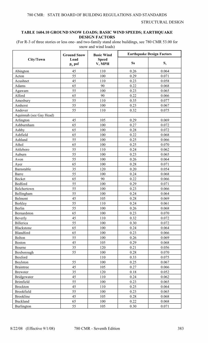
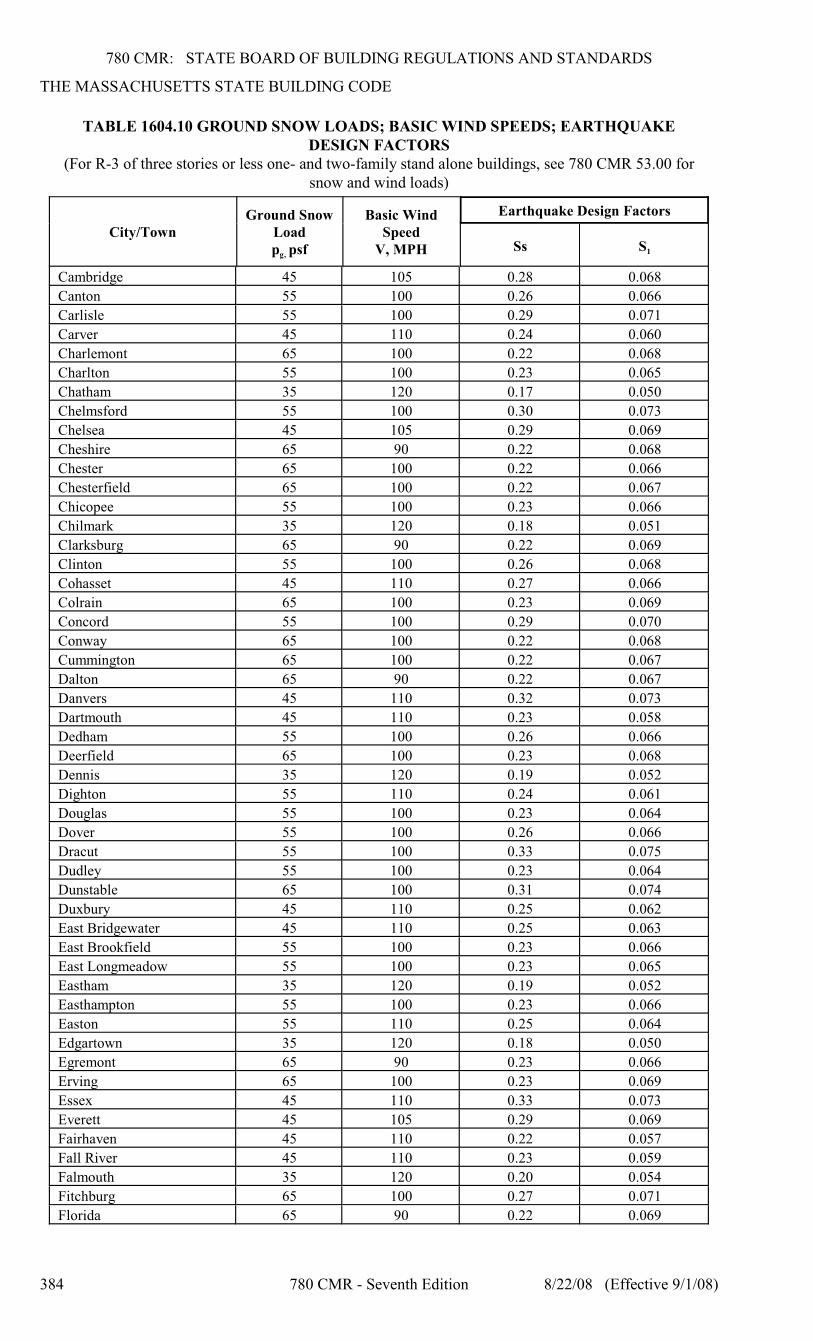
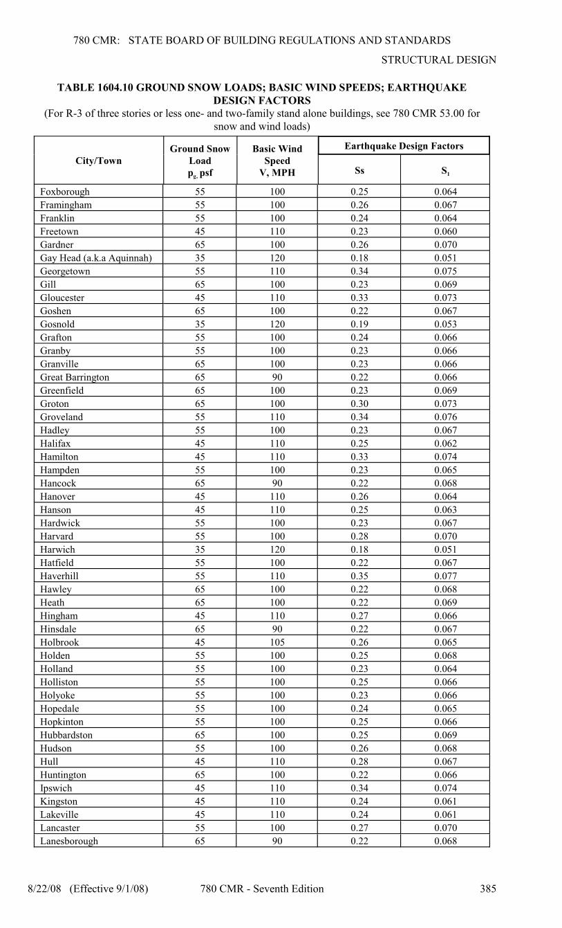
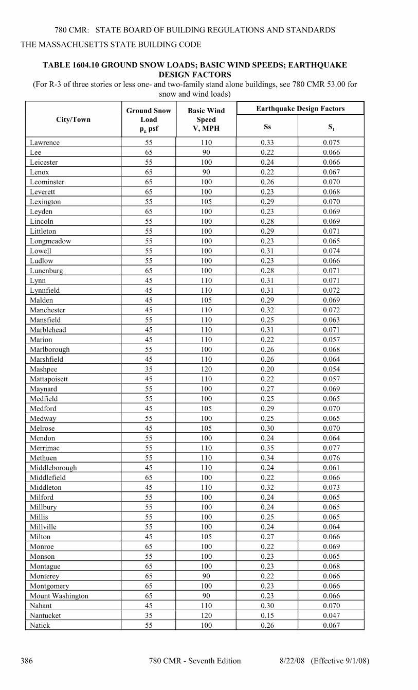
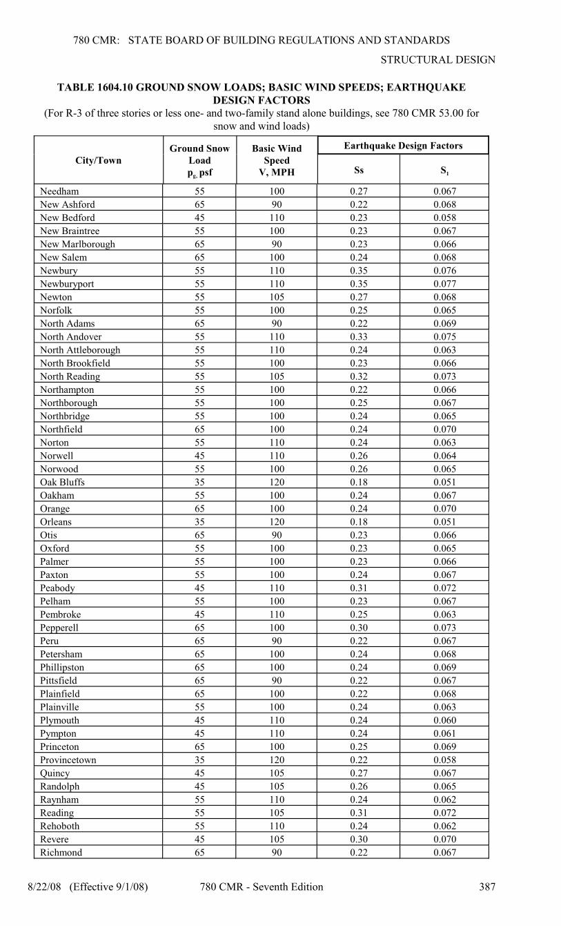
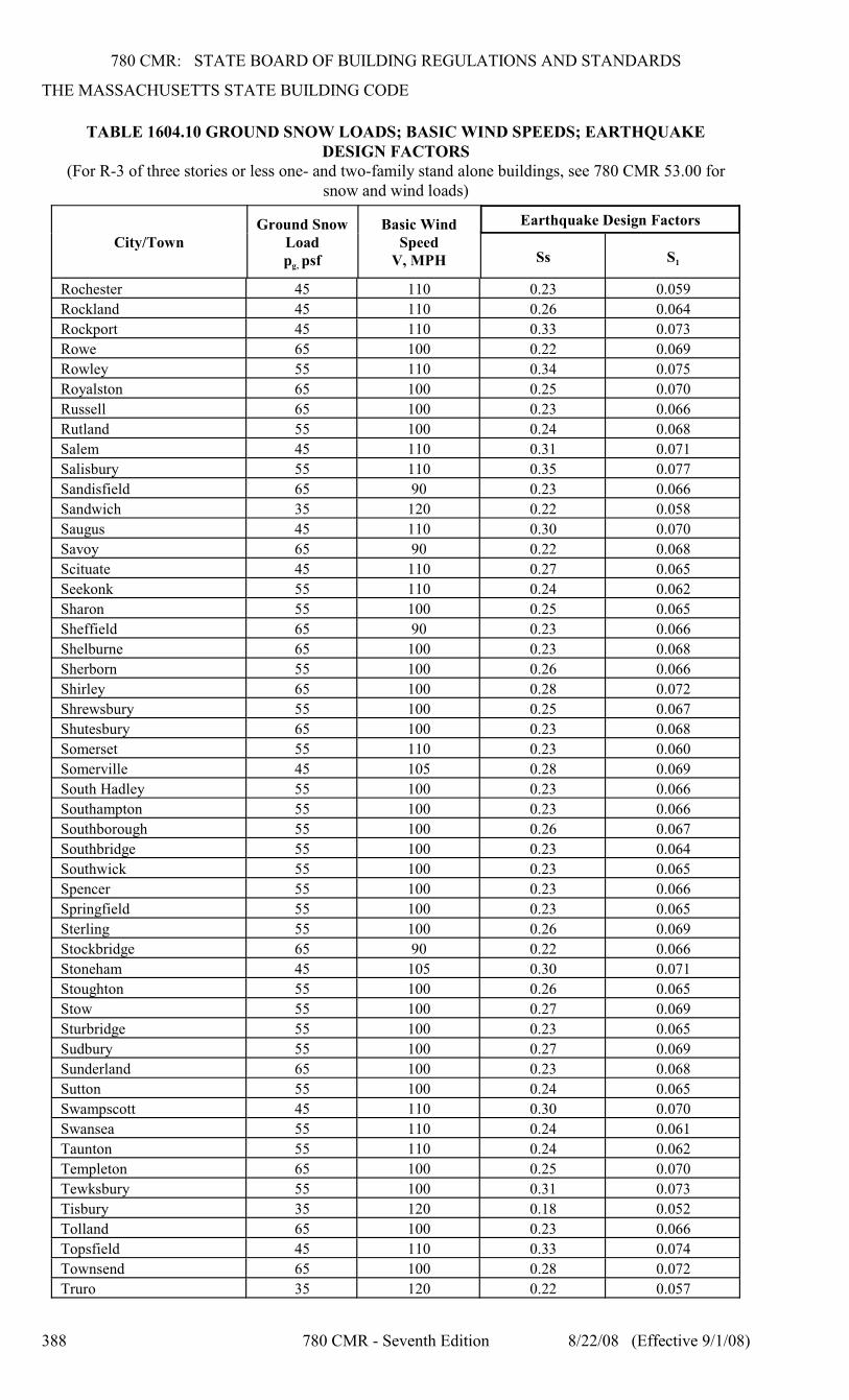
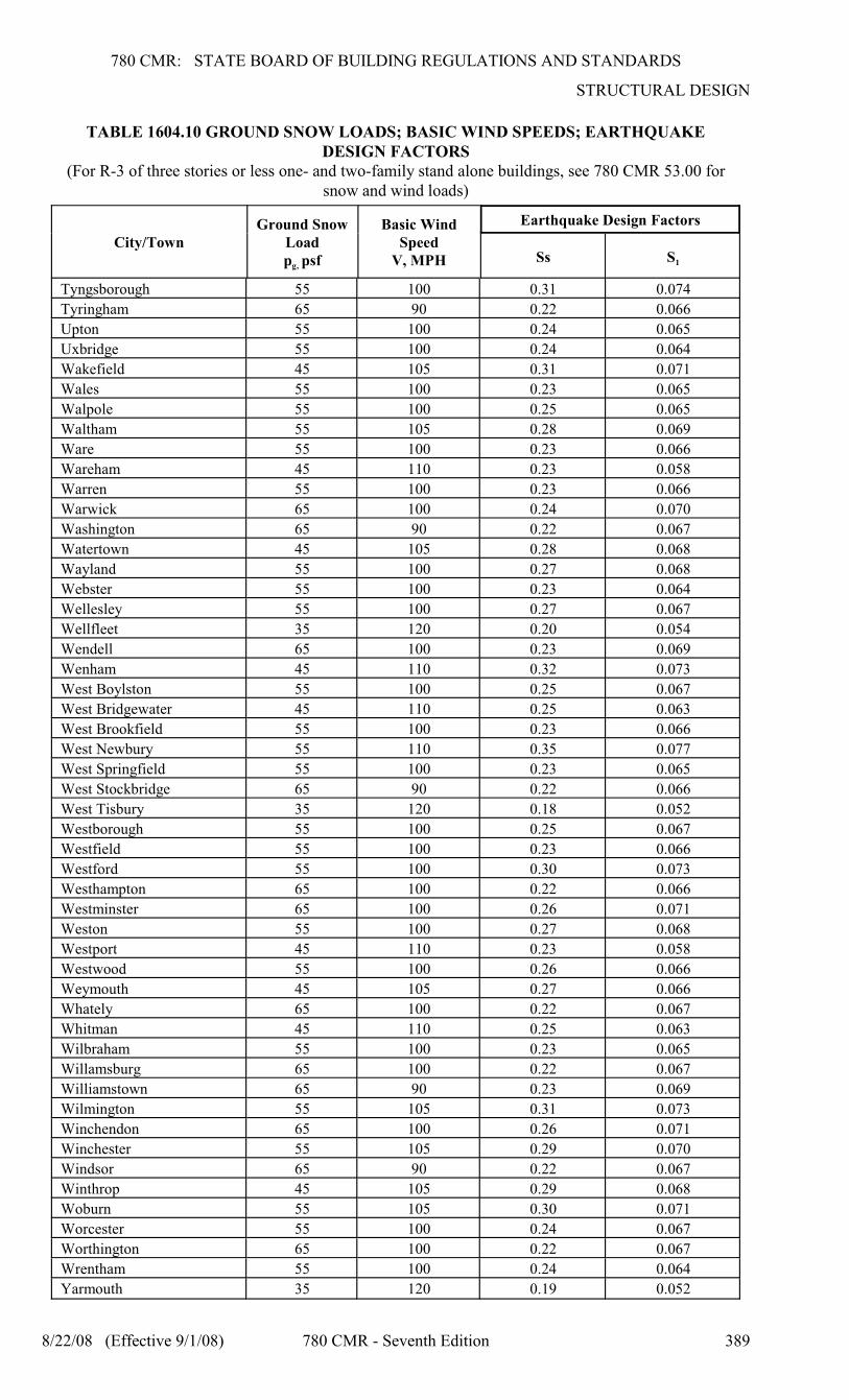
1604.10 Snow, Wind, and Earthquake Design
gFactors: Ground snow load, p , basic wind speed(three second gust speed), V, and earthquakeresponse accelerations for the maximum considered
S 1earthquake, S and S , for each city and town inMassachusetts shall be as given in Table 1604.10.
NOTE: Table 1604.10 Ground Sow Loads; BasicWind Speeds; Earthquake Design Factors applies,as applicable, to all use groups except for R-3One- and Two-family dwellings.
For ground snow loads and basic wind speedsfor R-3 of three stories or less one- and two-family stand alone dwellings, see 780 CMR53.00.
780 CMR: STATE BOARD OF BUILDING REGULATIONS AND STANDARDS
STRUCTURAL DESIGN
8/22/08 (Effective 9/1/08) 780 CMR - Seventh Edition 383
TABLE 1604.10 GROUND SNOW LOADS; BASIC WIND SPEEDS; EARTHQUAKEDESIGN FACTORS
(For R-3 of three stories or less one- and two-family stand alone buildings, see 780 CMR 53.00 forsnow and wind loads)
City/TownGround Snow
Load
g, p psf
Basic WindSpeed
V, MPH
Earthquake Design Factors
1Ss S
Abington 45 110 0.26 0.064
Acton 55 100 0.29 0.071
Acushnet 45 110 0.23 0.058
Adams 65 90 0.22 0.068
Agawam 55 100 0.23 0.065
Alford 65 90 0.22 0.066
Amesbury 55 110 0.35 0.077
Amherst 55 100 0.23 0.067
Andover 55 110 0.32 0.075
Aquinnah (see Gay Head)
Arlington 45 105 0.29 0.069
Ashburnham 65 100 0.27 0.072
Ashby 65 100 0.28 0.072
Ashfield 65 100 0.22 0.068
Ashland 55 100 0.25 0.066
Athol 65 100 0.25 0.070
Attleboro 55 110 0.24 0.062
Auburn 55 100 0.23 0.065
Avon 55 100 0.26 0.064
Ayer 65 100 0.28 0.071
Barnstable 35 120 0.20 0.054
Barre 55 100 0.24 0.068
Becket 65 90 0.22 0.066
Bedford 55 100 0.29 0.071
Belchertown 55 100 0.23 0.066
Bellingham 55 100 0.24 0.064
Belmont 45 105 0.28 0.069
Berkley 55 110 0.24 0.061
Berlin 55 100 0.26 0.068
Bernardston 65 100 0.23 0.070
Beverly 45 110 0.32 0.072
Billerica 55 100 0.30 0.072
Blackstone 65 100 0.24 0.064
Blandford 65 100 0.23 0.066
Bolton 55 100 0.26 0.069
Boston 45 105 0.29 0.068
Bourne 35 120 0.21 0.056
Boxborough 55 100 0.28 0.070
Boxford 110 0.33 0.075
Boylston 55 100 0.25 0.067
Braintree 45 105 0.27 0.066
Brewster 35 120 0.18 0.052
Bridgewater 45 110 0.24 0.062
Brimfield 55 100 0.23 0.065
Brockton 45 110 0.25 0.064
Brookfield 55 100 0.23 0.065
Brookline 45 105 0.28 0.068
Buckland 65 100 0.22 0.068
Burlington 55 105 0.30 0.071
780 CMR: STATE BOARD OF BUILDING REGULATIONS AND STANDARDS
THE MASSACHUSETTS STATE BUILDING CODE
TABLE 1604.10 GROUND SNOW LOADS; BASIC WIND SPEEDS; EARTHQUAKEDESIGN FACTORS
(For R-3 of three stories or less one- and two-family stand alone buildings, see 780 CMR 53.00 forsnow and wind loads)
City/TownGround Snow
Load
g, p psf
Basic WindSpeed
V, MPH
Earthquake Design Factors
1Ss S
384 780 CMR - Seventh Edition 8/22/08 (Effective 9/1/08)
Cambridge 45 105 0.28 0.068
Canton 55 100 0.26 0.066
Carlisle 55 100 0.29 0.071
Carver 45 110 0.24 0.060
Charlemont 65 100 0.22 0.068
Charlton 55 100 0.23 0.065
Chatham 35 120 0.17 0.050
Chelmsford 55 100 0.30 0.073
Chelsea 45 105 0.29 0.069
Cheshire 65 90 0.22 0.068
Chester 65 100 0.22 0.066
Chesterfield 65 100 0.22 0.067
Chicopee 55 100 0.23 0.066
Chilmark 35 120 0.18 0.051
Clarksburg 65 90 0.22 0.069
Clinton 55 100 0.26 0.068
Cohasset 45 110 0.27 0.066
Colrain 65 100 0.23 0.069
Concord 55 100 0.29 0.070
Conway 65 100 0.22 0.068
Cummington 65 100 0.22 0.067
Dalton 65 90 0.22 0.067
Danvers 45 110 0.32 0.073
Dartmouth 45 110 0.23 0.058
Dedham 55 100 0.26 0.066
Deerfield 65 100 0.23 0.068
Dennis 35 120 0.19 0.052
Dighton 55 110 0.24 0.061
Douglas 55 100 0.23 0.064
Dover 55 100 0.26 0.066
Dracut 55 100 0.33 0.075
Dudley 55 100 0.23 0.064
Dunstable 65 100 0.31 0.074
Duxbury 45 110 0.25 0.062
East Bridgewater 45 110 0.25 0.063
East Brookfield 55 100 0.23 0.066
East Longmeadow 55 100 0.23 0.065
Eastham 35 120 0.19 0.052
Easthampton 55 100 0.23 0.066
Easton 55 110 0.25 0.064
Edgartown 35 120 0.18 0.050
Egremont 65 90 0.23 0.066
Erving 65 100 0.23 0.069
Essex 45 110 0.33 0.073
Everett 45 105 0.29 0.069
Fairhaven 45 110 0.22 0.057
Fall River 45 110 0.23 0.059
Falmouth 35 120 0.20 0.054
Fitchburg 65 100 0.27 0.071
Florida 65 90 0.22 0.069
780 CMR: STATE BOARD OF BUILDING REGULATIONS AND STANDARDS
STRUCTURAL DESIGN
TABLE 1604.10 GROUND SNOW LOADS; BASIC WIND SPEEDS; EARTHQUAKEDESIGN FACTORS
(For R-3 of three stories or less one- and two-family stand alone buildings, see 780 CMR 53.00 forsnow and wind loads)
City/TownGround Snow
Load
g, p psf
Basic WindSpeed
V, MPH
Earthquake Design Factors
1Ss S
8/22/08 (Effective 9/1/08) 780 CMR - Seventh Edition 385
Foxborough 55 100 0.25 0.064
Framingham 55 100 0.26 0.067
Franklin 55 100 0.24 0.064
Freetown 45 110 0.23 0.060
Gardner 65 100 0.26 0.070
Gay Head (a.k.a Aquinnah) 35 120 0.18 0.051
Georgetown 55 110 0.34 0.075
Gill 65 100 0.23 0.069
Gloucester 45 110 0.33 0.073
Goshen 65 100 0.22 0.067
Gosnold 35 120 0.19 0.053
Grafton 55 100 0.24 0.066
Granby 55 100 0.23 0.066
Granville 65 100 0.23 0.066
Great Barrington 65 90 0.22 0.066
Greenfield 65 100 0.23 0.069
Groton 65 100 0.30 0.073
Groveland 55 110 0.34 0.076
Hadley 55 100 0.23 0.067
Halifax 45 110 0.25 0.062
Hamilton 45 110 0.33 0.074
Hampden 55 100 0.23 0.065
Hancock 65 90 0.22 0.068
Hanover 45 110 0.26 0.064
Hanson 45 110 0.25 0.063
Hardwick 55 100 0.23 0.067
Harvard 55 100 0.28 0.070
Harwich 35 120 0.18 0.051
Hatfield 55 100 0.22 0.067
Haverhill 55 110 0.35 0.077
Hawley 65 100 0.22 0.068
Heath 65 100 0.22 0.069
Hingham 45 110 0.27 0.066
Hinsdale 65 90 0.22 0.067
Holbrook 45 105 0.26 0.065
Holden 55 100 0.25 0.068
Holland 55 100 0.23 0.064
Holliston 55 100 0.25 0.066
Holyoke 55 100 0.23 0.066
Hopedale 55 100 0.24 0.065
Hopkinton 55 100 0.25 0.066
Hubbardston 65 100 0.25 0.069
Hudson 55 100 0.26 0.068
Hull 45 110 0.28 0.067
Huntington 65 100 0.22 0.066
Ipswich 45 110 0.34 0.074
Kingston 45 110 0.24 0.061
Lakeville 45 110 0.24 0.061
Lancaster 55 100 0.27 0.070
Lanesborough 65 90 0.22 0.068
780 CMR: STATE BOARD OF BUILDING REGULATIONS AND STANDARDS
THE MASSACHUSETTS STATE BUILDING CODE
TABLE 1604.10 GROUND SNOW LOADS; BASIC WIND SPEEDS; EARTHQUAKEDESIGN FACTORS
(For R-3 of three stories or less one- and two-family stand alone buildings, see 780 CMR 53.00 forsnow and wind loads)
City/TownGround Snow
Load
g, p psf
Basic WindSpeed
V, MPH
Earthquake Design Factors
1Ss S
386 780 CMR - Seventh Edition 8/22/08 (Effective 9/1/08)
Lawrence 55 110 0.33 0.075
Lee 65 90 0.22 0.066
Leicester 55 100 0.24 0.066
Lenox 65 90 0.22 0.067
Leominster 65 100 0.26 0.070
Leverett 65 100 0.23 0.068
Lexington 55 105 0.29 0.070
Leyden 65 100 0.23 0.069
Lincoln 55 100 0.28 0.069
Littleton 55 100 0.29 0.071
Longmeadow 55 100 0.23 0.065
Lowell 55 100 0.31 0.074
Ludlow 55 100 0.23 0.066
Lunenburg 65 100 0.28 0.071
Lynn 45 110 0.31 0.071
Lynnfield 45 110 0.31 0.072
Malden 45 105 0.29 0.069
Manchester 45 110 0.32 0.072
Mansfield 55 110 0.25 0.063
Marblehead 45 110 0.31 0.071
Marion 45 110 0.22 0.057
Marlborough 55 100 0.26 0.068
Marshfield 45 110 0.26 0.064
Mashpee 35 120 0.20 0.054
Mattapoisett 45 110 0.22 0.057
Maynard 55 100 0.27 0.069
Medfield 55 100 0.25 0.065
Medford 45 105 0.29 0.070
Medway 55 100 0.25 0.065
Melrose 45 105 0.30 0.070
Mendon 55 100 0.24 0.064
Merrimac 55 110 0.35 0.077
Methuen 55 110 0.34 0.076
Middleborough 45 110 0.24 0.061
Middlefield 65 100 0.22 0.066
Middleton 45 110 0.32 0.073
Milford 55 100 0.24 0.065
Millbury 55 100 0.24 0.065
Millis 55 100 0.25 0.065
Millville 55 100 0.24 0.064
Milton 45 105 0.27 0.066
Monroe 65 100 0.22 0.069
Monson 55 100 0.23 0.065
Montague 65 100 0.23 0.068
Monterey 65 90 0.22 0.066
Montgomery 65 100 0.23 0.066
Mount Washington 65 90 0.23 0.066
Nahant 45 110 0.30 0.070
Nantucket 35 120 0.15 0.047
Natick 55 100 0.26 0.067
780 CMR: STATE BOARD OF BUILDING REGULATIONS AND STANDARDS
STRUCTURAL DESIGN
TABLE 1604.10 GROUND SNOW LOADS; BASIC WIND SPEEDS; EARTHQUAKEDESIGN FACTORS
(For R-3 of three stories or less one- and two-family stand alone buildings, see 780 CMR 53.00 forsnow and wind loads)
City/TownGround Snow
Load
g, p psf
Basic WindSpeed
V, MPH
Earthquake Design Factors
1Ss S
8/22/08 (Effective 9/1/08) 780 CMR - Seventh Edition 387
Needham 55 100 0.27 0.067
New Ashford 65 90 0.22 0.068
New Bedford 45 110 0.23 0.058
New Braintree 55 100 0.23 0.067
New Marlborough 65 90 0.23 0.066
New Salem 65 100 0.24 0.068
Newbury 55 110 0.35 0.076
Newburyport 55 110 0.35 0.077
Newton 55 105 0.27 0.068
Norfolk 55 100 0.25 0.065
North Adams 65 90 0.22 0.069
North Andover 55 110 0.33 0.075
North Attleborough 55 110 0.24 0.063
North Brookfield 55 100 0.23 0.066
North Reading 55 105 0.32 0.073
Northampton 55 100 0.22 0.066
Northborough 55 100 0.25 0.067
Northbridge 55 100 0.24 0.065
Northfield 65 100 0.24 0.070
Norton 55 110 0.24 0.063
Norwell 45 110 0.26 0.064
Norwood 55 100 0.26 0.065
Oak Bluffs 35 120 0.18 0.051
Oakham 55 100 0.24 0.067
Orange 65 100 0.24 0.070
Orleans 35 120 0.18 0.051
Otis 65 90 0.23 0.066
Oxford 55 100 0.23 0.065
Palmer 55 100 0.23 0.066
Paxton 55 100 0.24 0.067
Peabody 45 110 0.31 0.072
Pelham 55 100 0.23 0.067
Pembroke 45 110 0.25 0.063
Pepperell 65 100 0.30 0.073
Peru 65 90 0.22 0.067
Petersham 65 100 0.24 0.068
Phillipston 65 100 0.24 0.069
Pittsfield 65 90 0.22 0.067
Plainfield 65 100 0.22 0.068
Plainville 55 100 0.24 0.063
Plymouth 45 110 0.24 0.060
Pympton 45 110 0.24 0.061
Princeton 65 100 0.25 0.069
Provincetown 35 120 0.22 0.058
Quincy 45 105 0.27 0.067
Randolph 45 105 0.26 0.065
Raynham 55 110 0.24 0.062
Reading 55 105 0.31 0.072
Rehoboth 55 110 0.24 0.062
Revere 45 105 0.30 0.070
Richmond 65 90 0.22 0.067
780 CMR: STATE BOARD OF BUILDING REGULATIONS AND STANDARDS
THE MASSACHUSETTS STATE BUILDING CODE
TABLE 1604.10 GROUND SNOW LOADS; BASIC WIND SPEEDS; EARTHQUAKEDESIGN FACTORS
(For R-3 of three stories or less one- and two-family stand alone buildings, see 780 CMR 53.00 forsnow and wind loads)
City/TownGround Snow
Load
g, p psf
Basic WindSpeed
V, MPH
Earthquake Design Factors
1Ss S
388 780 CMR - Seventh Edition 8/22/08 (Effective 9/1/08)
Rochester 45 110 0.23 0.059
Rockland 45 110 0.26 0.064
Rockport 45 110 0.33 0.073
Rowe 65 100 0.22 0.069
Rowley 55 110 0.34 0.075
Royalston 65 100 0.25 0.070
Russell 65 100 0.23 0.066
Rutland 55 100 0.24 0.068
Salem 45 110 0.31 0.071
Salisbury 55 110 0.35 0.077
Sandisfield 65 90 0.23 0.066
Sandwich 35 120 0.22 0.058
Saugus 45 110 0.30 0.070
Savoy 65 90 0.22 0.068
Scituate 45 110 0.27 0.065
Seekonk 55 110 0.24 0.062
Sharon 55 100 0.25 0.065
Sheffield 65 90 0.23 0.066
Shelburne 65 100 0.23 0.068
Sherborn 55 100 0.26 0.066
Shirley 65 100 0.28 0.072
Shrewsbury 55 100 0.25 0.067
Shutesbury 65 100 0.23 0.068
Somerset 55 110 0.23 0.060
Somerville 45 105 0.28 0.069
South Hadley 55 100 0.23 0.066
Southampton 55 100 0.23 0.066
Southborough 55 100 0.26 0.067
Southbridge 55 100 0.23 0.064
Southwick 55 100 0.23 0.065
Spencer 55 100 0.23 0.066
Springfield 55 100 0.23 0.065
Sterling 55 100 0.26 0.069
Stockbridge 65 90 0.22 0.066
Stoneham 45 105 0.30 0.071
Stoughton 55 100 0.26 0.065
Stow 55 100 0.27 0.069
Sturbridge 55 100 0.23 0.065
Sudbury 55 100 0.27 0.069
Sunderland 65 100 0.23 0.068
Sutton 55 100 0.24 0.065
Swampscott 45 110 0.30 0.070
Swansea 55 110 0.24 0.061
Taunton 55 110 0.24 0.062
Templeton 65 100 0.25 0.070
Tewksbury 55 100 0.31 0.073
Tisbury 35 120 0.18 0.052
Tolland 65 100 0.23 0.066
Topsfield 45 110 0.33 0.074
Townsend 65 100 0.28 0.072
Truro 35 120 0.22 0.057
780 CMR: STATE BOARD OF BUILDING REGULATIONS AND STANDARDS
STRUCTURAL DESIGN
TABLE 1604.10 GROUND SNOW LOADS; BASIC WIND SPEEDS; EARTHQUAKEDESIGN FACTORS
(For R-3 of three stories or less one- and two-family stand alone buildings, see 780 CMR 53.00 forsnow and wind loads)
City/TownGround Snow
Load
g, p psf
Basic WindSpeed
V, MPH
Earthquake Design Factors
1Ss S
8/22/08 (Effective 9/1/08) 780 CMR - Seventh Edition 389
Tyngsborough 55 100 0.31 0.074
Tyringham 65 90 0.22 0.066
Upton 55 100 0.24 0.065
Uxbridge 55 100 0.24 0.064
Wakefield 45 105 0.31 0.071
Wales 55 100 0.23 0.065
Walpole 55 100 0.25 0.065
Waltham 55 105 0.28 0.069
Ware 55 100 0.23 0.066
Wareham 45 110 0.23 0.058
Warren 55 100 0.23 0.066
Warwick 65 100 0.24 0.070
Washington 65 90 0.22 0.067
Watertown 45 105 0.28 0.068
Wayland 55 100 0.27 0.068
Webster 55 100 0.23 0.064
Wellesley 55 100 0.27 0.067
Wellfleet 35 120 0.20 0.054
Wendell 65 100 0.23 0.069
Wenham 45 110 0.32 0.073
West Boylston 55 100 0.25 0.067
West Bridgewater 45 110 0.25 0.063
West Brookfield 55 100 0.23 0.066
West Newbury 55 110 0.35 0.077
West Springfield 55 100 0.23 0.065
West Stockbridge 65 90 0.22 0.066
West Tisbury 35 120 0.18 0.052
Westborough 55 100 0.25 0.067
Westfield 55 100 0.23 0.066
Westford 55 100 0.30 0.073
Westhampton 65 100 0.22 0.066
Westminster 65 100 0.26 0.071
Weston 55 100 0.27 0.068
Westport 45 110 0.23 0.058
Westwood 55 100 0.26 0.066
Weymouth 45 105 0.27 0.066
Whately 65 100 0.22 0.067
Whitman 45 110 0.25 0.063
Wilbraham 55 100 0.23 0.065
Willamsburg 65 100 0.22 0.067
Williamstown 65 90 0.23 0.069
Wilmington 55 105 0.31 0.073
Winchendon 65 100 0.26 0.071
Winchester 55 105 0.29 0.070
Windsor 65 90 0.22 0.067
Winthrop 45 105 0.29 0.068
Woburn 55 105 0.30 0.071
Worcester 55 100 0.24 0.067
Worthington 65 100 0.22 0.067
Wrentham 55 100 0.24 0.064
Yarmouth 35 120 0.19 0.052
780 CMR: STATE BOARD OF BUILDING REGULATIONS AND STANDARDS
THE MASSACHUSETTS STATE BUILDING CODE
390 780 CMR - Seventh Edition 8/22/08 (Effective 9/1/08)
780 CMR 1605.0 LOAD COMBINATIONS
1605.1 General. Buildings and other structures andportions thereof shall be designed to resist the loadcombinations specified in 780 CMR 1605.2 or1605.3 and 780 CMR 18.00 through 23.00, and loadcombinations which include the special seismic loadof ASCE 7, Section 9.5.2.7.1, where required byASCE 7, Section 9.5.2.6.2.11 or 9.5.2.6.3.1.Applicable loads shall be considered, including bothearthquake and wind, in accordance with thespecified load combinations. Each load combinationshall also be investigated with one or more of thevariable loads set to zero.
1605.2 Load Combinations Using Strength Designor Load and Resistance Factor Design.
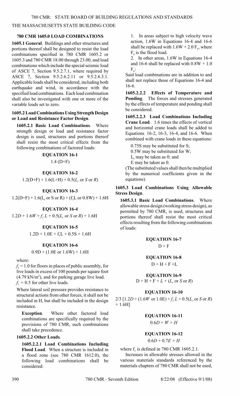
1605.2.1 Basic Load Combinations. Wherestrength design or load and resistance factordesign is used, structures and portions thereofshall resist the most critical effects from thefollowing combinations of factored loads:
EQUATION 16-1
1.4 (D+F)
EQUATION 16-2
r1.2(D+F) + 1.6(L+H) + 0.5(L or S or R)
EQUATION 16-3
r 11.2(D+F) + 1.6(L or S or R) + (f L or 0.8W) + 1.6H
EQUATION 16-4
1 r1.2D + 1.6W + f L + 0.5(L or S or R) + 1.6H
EQUATION 16-5
11.2D + 1.0E + f L + 0.5S + 1.6H
EQUATION 16-6
0.9D + (1.0E or 1.6W) + 1.6H
where:
1f = 1.0 for floors in places of public assembly, forlive loads in excess of 100 pounds per square foot(4.79 kN/m ), and for parking garage live load.2
1f = 0.5 for other live loads.
Where lateral soil pressure provides resistance tostructural actions from other forces, it shall not beincluded in H, but shall be included in the designresistance.
Exception. Where other factored loadcombinations are specifically required by theprovisions of 780 CMR, such combinationsshall take precedence.
1605.2.2 Other Loads.
1605.2.2.1 Load Combinations IncludingFlood Load. When a structure is included ina flood zone (see 780 CMR 1612.0), thefollowing load combinations shall beconsidered:
1. In areas subject to high velocity waveaction, 1.6W in Equations 16-4 and 16-6
ashall be replaced with 1.6W + 2.0 F , where
aF is the flood load.2. In other areas, 1.6W in Equations 16-4and 16-6 shall be replaced with 0.8W + 1.0
aF :Said load combinations are in addition to andshall not replace those of Equations 16-4 and16-6.
1605.2.2.2 Effects of Temperature andPonding. The forces and stresses generatedby the effects of temperature and ponding shallbe considered.
1605.2.2.3 Load Combinations IncludingCrane Load. 1.6 times the effects of verticaland horizontal crane loads shall be added toEquations 16-2, 16-3, 16-4, and 16-6. Whencombined with crane loads in these equations:
0.75S may be substituted for S;0.5W may be substituted for W;
rL may be taken as 0; andE may be taken as 0.
(The substituted values shall then be multipliedby the numerical coefficients given in theequations).
1605.3 Load Combinations Using AllowableStress Design.
1605.3.1 Basic Load Combinations. Whereallowable stress design (working stress design), aspermitted by 780 CMR, is used, structures andportions thereof shall resist the most criticaleffects resulting from the following combinationsof loads:
EQUATION 16-7
D + F
EQUATION 16-8
D + H + F +L
EQUATION 16-9
r D + H + F + L + (L or S or R)
EQUATION 16-10
1 r2/3 [1.2D + (1.6W or 1.0E) + f L + 0.5(L or S or R)+ 1.6H]
EQUATION 16-11
0.6D + W + H
EQUATION 16-12
0.6D + 0.7E + H
1where f is defined in 780 CMR 1605.2.1.Increases in allowable stresses allowed in the
various materials standards referenced by thematerials chapters of 780 CMR shall not be used,
780 CMR: STATE BOARD OF BUILDING REGULATIONS AND STANDARDS
STRUCTURAL DESIGN
8/22/08 (Effective 9/1/08) 780 CMR - Seventh Edition 391
except that a duration of load increase shall bepermitted in accordance with 780 CMR 23.00.
Where lateral soil pressure provides resistanceto structural actions from other forces, it shall notbe included in H, but shall be included in thedesign resistance.
1605.3.2 Other Loads.
1605.3.2.1 Load Combinations IncludingFlood Load. When a structure is included ina flood zone (see 780 CMR 1612), thefollowing load combinations shall beconsidered:
1. In areas subject to high velocity wave
aaction, 1.5 F shall be added to other loads
ain Equations 16-10 and 16-11, where F isthe flood load, and E shall be set to zero inEquation 16-10.
a2. In other areas, 0.75 F shall be added toother loads in Equations 16-10 and 16-11,and E shall be set to zero in Equation 16-10.
Said load combinations are in addition to andshall not replace those of Equations 16-10 and16-11.
1605.3.2.2 Effects of Temperature andPonding. The forces and stresses generated bythe effects of temperature and ponding shall beconsidered.1605.3.2.3 Load Combinations IncludingCrane Load. 1.0 times the effects of verticaland horizontal crane loads shall be added toEquations 16-8, 16-9, 16-10, and 16-12. Whencombined with crane loads in these equations:
0.75S may be substituted for S;0.5W may be substituted for W;
rL may be taken as 0; andE may be taken as 0.
(The substituted values shall then be multipliedby the numerical coefficients, if any, given inthe equations).
1605.4 Heliports and Helistops. Heliport andhelistop landing or touchdown areas shall bedesigned for the following loads, combined inaccordance with 780 CMR 1605.0:
1. Dead load, D, plus the gross weight of the
hhelicopter, D , plus snow load, S.2. Dead load, D, plus two single concentratedimpact loads, L, approximately 8 feet (2438 mm)apart applied anywhere on the touchdown pad(representing each of the helicopter’s two mainlanding gear, whether skid type or wheeled type),having a magnitude of 0.75 times the gross weightof the helicopter. Both loads acting together total1.5 times the gross weight of the helicopter.3. Dead load, D, plus a uniform live load, L, of100 pounds per square foot (4.79 kN/m ).2
780 CMR 1606.0 DEAD LOADS
1606.1 Weights of Materials and Construction. In
determining dead loads for purposes of design, theactual weights of materials and construction shall beused but not less than the applicable minimumdesign dead loads given in Table C3-1 of ASCE 7.In the absence of definite information, values usedshall be subject to the approval of the buildingofficial.
1606.2 Weights of Fixed Service Equipment. Indetermining dead loads for purposes of design, theweight of fixed service equipment, such as plumbingstacks and risers, electrical feeders, heating,ventilating and air conditioning systems and firesprinkler systems, shall be included.
1606.3 Weight of Concrete Due to Deflection.Account shall be taken of the additional weight ofconcrete resulting from the deflection of thesupporting deck and framing when placing concrete.
1606.4 Weight of Ceilings: Provision shall memade for the weight of ceilings, lights, ducts, andpipes which can be supported within or under theframing of floors or roofs, whether they are presentlyinstalled or whether they can be subsequentlyinstalled.
780 CMR 1607.0 LIVE LOADS
1607.1 General. Live loads are those loads definedin 780 CMR 1602.1.
1607.2 Loads Not Specified. For occupancies oruses not designated in Table 1607.1, the live loadshall be determined in accordance with a methodapproved by the building official.
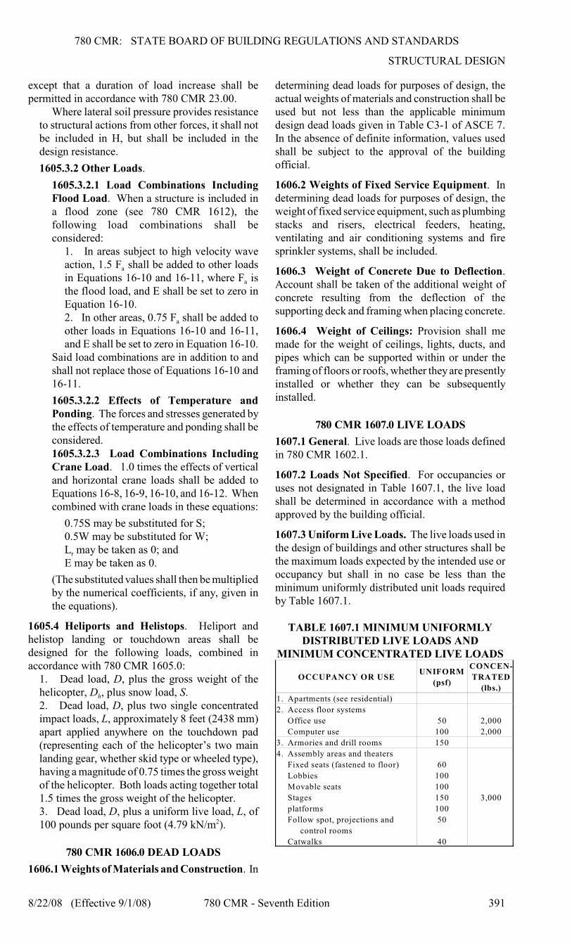
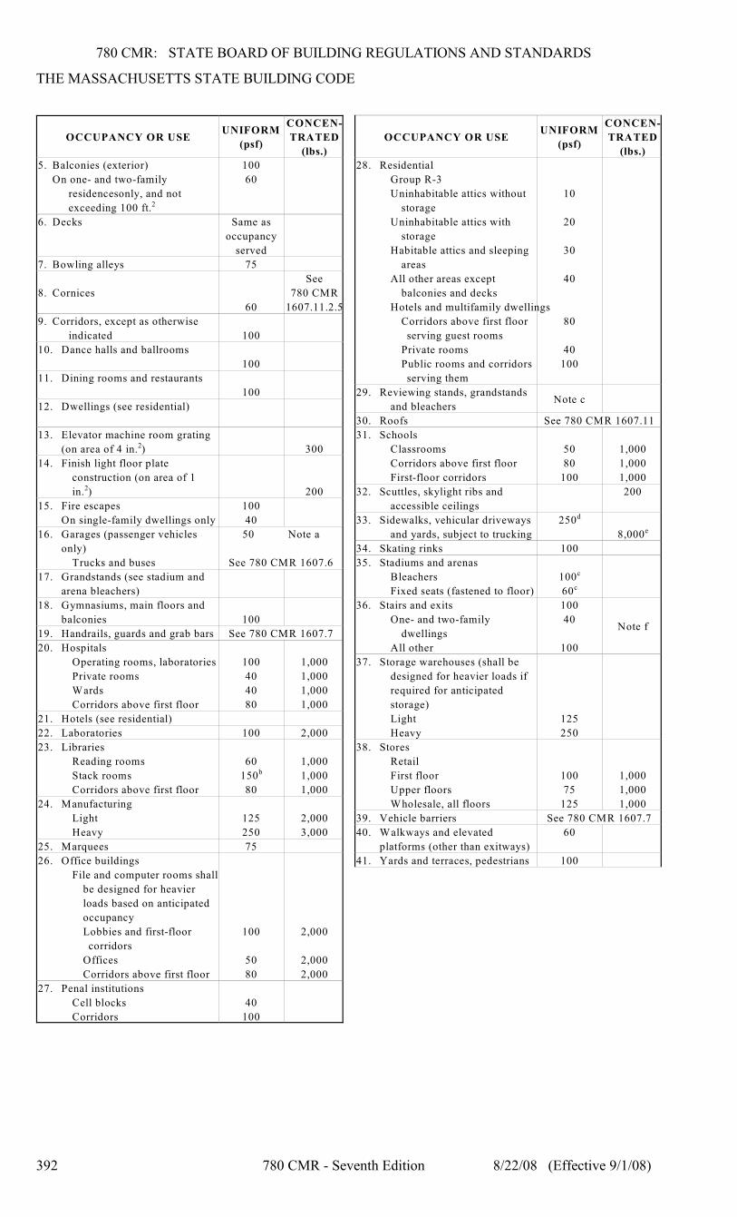
1607.3 Uniform Live Loads. The live loads used inthe design of buildings and other structures shall bethe maximum loads expected by the intended use oroccupancy but shall in no case be less than theminimum uniformly distributed unit loads requiredby Table 1607.1.
TABLE 1607.1 MINIMUM UNIFORMLYDISTRIBUTED LIVE LOADS AND
MINIMUM CONCENTRATED LIVE LOADS
OCCUPANCY OR USEUNIFORM
(psf)
CONCEN-
TRATED
(lbs.)
1. Apartments (see residential)
2. Access floor systems
Office use
Computer use
50
100
2,000
2,000
3. Armories and drill rooms 150
4. Assembly areas and theaters
Fixed seats (fastened to floor)
Lobbies
Movable seats
Stages
platforms
Follow spot, projections and
control rooms
Catwalks
60
100
100
150
100
50
40
3,000
780 CMR: STATE BOARD OF BUILDING REGULATIONS AND STANDARDS
THE MASSACHUSETTS STATE BUILDING CODE
392 780 CMR - Seventh Edition 8/22/08 (Effective 9/1/08)
OCCUPANCY OR USEUNIFORM
(psf)
CONCEN-
TRATED
(lbs.)
5. Balconies (exterior)
On one- and two-family
residencesonly, and not
exceeding 100 ft.2
100
60
6. Decks Same as
occupancy
served
7. Bowling alleys 75
8. Cornices
60
See
780 CMR
1607.11.2.5
9. Corridors, except as otherwise
indicated 100
10. Dance halls and ballrooms
100
11. Dining rooms and restaurants
100
12. Dwellings (see residential)
13. Elevator machine room grating
(on area of 4 in. ) 3002
14. Finish light floor plate
construction (on area of 1
in. ) 2002
15. Fire escapes
On single-family dwellings only
100
40
16. Garages (passenger vehicles
only)
Trucks and buses
50 Note a
See 780 CMR 1607.6
17. Grandstands (see stadium and
arena bleachers)
18. Gymnasiums, main floors and
balconies 100
19. Handrails, guards and grab bars See 780 CMR 1607.7
20. Hospitals
Operating rooms, laboratories
Private rooms
Wards
Corridors above first floor
100
40
40
80
1,000
1,000
1,000
1,000
21. Hotels (see residential)
22. Laboratories 100 2,000
23. Libraries
Reading rooms
Stack rooms
Corridors above first floor
60
150b
80
1,000
1,000
1,000
24. Manufacturing
Light
Heavy
125
250
2,000
3,000
25. Marquees 75
26. Office buildings
File and computer rooms shall
be designed for heavier
loads based on anticipated
occupancy
Lobbies and first-floor
corridors
Offices
Corridors above first floor
100
50
80
2,000
2,000
2,000
27. Penal institutions
Cell blocks
Corridors
40
100
OCCUPANCY OR USEUNIFORM
(psf)
CONCEN-
TRATED
(lbs.)
28. Residential
Group R-3
Uninhabitable attics without
storage
Uninhabitable attics with
storage
Habitable attics and sleeping
areas
All other areas except
balconies and decks
Hotels and multifamily dwellings
Corridors above first floor
serving guest rooms
Private rooms
Public rooms and corridors
serving them
10
20
30
40
80
40
100
29. Reviewing stands, grandstands
and bleachersNote c
30. Roofs See 780 CMR 1607.11
31. Schools
Classrooms
Corridors above first floor
First-floor corridors
50
80
100
1,000
1,000
1,000
32. Scuttles, skylight ribs and
accessible ceilings
200
33. Sidewalks, vehicular driveways
and yards, subject to trucking
250d
8,000e
34. Skating rinks 100
35. Stadiums and arenas
Bleachers
Fixed seats (fastened to floor)
100c
60c
36. Stairs and exits
One- and two-family
dwellings
All other
100
40
100
Note f
37. Storage warehouses (shall be
designed for heavier loads if
required for anticipated
storage)
Light
Heavy
125
250
38. Stores
Retail
First floor
Upper floors
Wholesale, all floors
100
75
125
1,000
1,000
1,000
39. Vehicle barriers See 780 CMR 1607.7
40. Walkways and elevated
platforms (other than exitways)
60
41. Yards and terraces, pedestrians 100
780 CMR: STATE BOARD OF BUILDING REGULATIONS AND STANDARDS
STRUCTURAL DESIGN
8/22/08 (Effective 9/1/08) 780 CMR - Seventh Edition 393
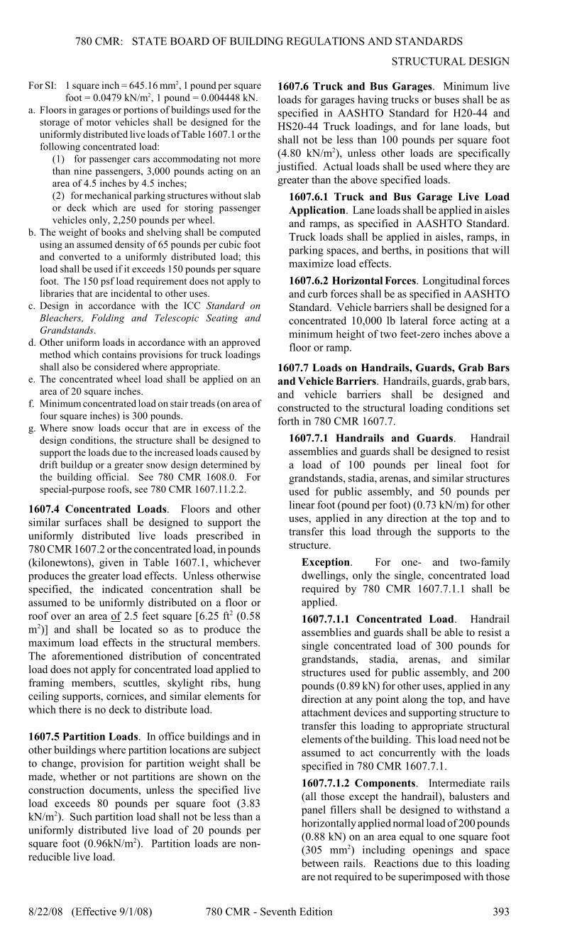
For SI: 1 square inch = 645.16 mm , 1 pound per square2
foot = 0.0479 kN/m , 1 pound = 0.004448 kN.2
a. Floors in garages or portions of buildings used for thestorage of motor vehicles shall be designed for theuniformly distributed live loads of Table 1607.1 or thefollowing concentrated load:
(1) for passenger cars accommodating not morethan nine passengers, 3,000 pounds acting on anarea of 4.5 inches by 4.5 inches;(2) for mechanical parking structures without slabor deck which are used for storing passengervehicles only, 2,250 pounds per wheel.
b. The weight of books and shelving shall be computedusing an assumed density of 65 pounds per cubic footand converted to a uniformly distributed load; thisload shall be used if it exceeds 150 pounds per squarefoot. The 150 psf load requirement does not apply tolibraries that are incidental to other uses.
c. Design in accordance with the ICC Standard onBleachers, Folding and Telescopic Seating andGrandstands.
d. Other uniform loads in accordance with an approvedmethod which contains provisions for truck loadingsshall also be considered where appropriate.
e. The concentrated wheel load shall be applied on anarea of 20 square inches.
f. Minimum concentrated load on stair treads (on area offour square inches) is 300 pounds.
g. Where snow loads occur that are in excess of thedesign conditions, the structure shall be designed tosupport the loads due to the increased loads caused bydrift buildup or a greater snow design determined bythe building official. See 780 CMR 1608.0. Forspecial-purpose roofs, see 780 CMR 1607.11.2.2.
1607.4 Concentrated Loads. Floors and othersimilar surfaces shall be designed to support theuniformly distributed live loads prescribed in780 CMR 1607.2 or the concentrated load, in pounds(kilonewtons), given in Table 1607.1, whicheverproduces the greater load effects. Unless otherwisespecified, the indicated concentration shall beassumed to be uniformly distributed on a floor orroof over an area of 2.5 feet square [6.25 ft (0.582
m )] and shall be located so as to produce the2
maximum load effects in the structural members.The aforementioned distribution of concentratedload does not apply for concentrated load applied toframing members, scuttles, skylight ribs, hungceiling supports, cornices, and similar elements forwhich there is no deck to distribute load.
1607.5 Partition Loads. In office buildings and inother buildings where partition locations are subjectto change, provision for partition weight shall bemade, whether or not partitions are shown on theconstruction documents, unless the specified liveload exceeds 80 pounds per square foot (3.83kN/m ). Such partition load shall not be less than a2
uniformly distributed live load of 20 pounds persquare foot (0.96kN/m ). Partition loads are non-2
reducible live load.
1607.6 Truck and Bus Garages. Minimum liveloads for garages having trucks or buses shall be asspecified in AASHTO Standard for H20-44 andHS20-44 Truck loadings, and for lane loads, butshall not be less than 100 pounds per square foot(4.80 kN/m ), unless other loads are specifically2
justified. Actual loads shall be used where they aregreater than the above specified loads.
1607.6.1 Truck and Bus Garage Live LoadApplication. Lane loads shall be applied in aislesand ramps, as specified in AASHTO Standard.Truck loads shall be applied in aisles, ramps, inparking spaces, and berths, in positions that willmaximize load effects.
1607.6.2 Horizontal Forces. Longitudinal forcesand curb forces shall be as specified in AASHTOStandard. Vehicle barriers shall be designed for aconcentrated 10,000 lb lateral force acting at aminimum height of two feet-zero inches above afloor or ramp.
1607.7 Loads on Handrails, Guards, Grab Barsand Vehicle Barriers. Handrails, guards, grab bars,and vehicle barriers shall be designed andconstructed to the structural loading conditions setforth in 780 CMR 1607.7.
1607.7.1 Handrails and Guards. Handrailassemblies and guards shall be designed to resista load of 100 pounds per lineal foot forgrandstands, stadia, arenas, and similar structuresused for public assembly, and 50 pounds perlinear foot (pound per foot) (0.73 kN/m) for otheruses, applied in any direction at the top and totransfer this load through the supports to thestructure.
Exception. For one- and two-familydwellings, only the single, concentrated loadrequired by 780 CMR 1607.7.1.1 shall beapplied.
1607.7.1.1 Concentrated Load. Handrailassemblies and guards shall be able to resist asingle concentrated load of 300 pounds forgrandstands, stadia, arenas, and similarstructures used for public assembly, and 200pounds (0.89 kN) for other uses, applied in anydirection at any point along the top, and haveattachment devices and supporting structure totransfer this loading to appropriate structuralelements of the building. This load need not beassumed to act concurrently with the loadsspecified in 780 CMR 1607.7.1.
1607.7.1.2 Components. Intermediate rails(all those except the handrail), balusters andpanel fillers shall be designed to withstand ahorizontally applied normal load of 200 pounds(0.88 kN) on an area equal to one square foot(305 mm ) including openings and space2
between rails. Reactions due to this loadingare not required to be superimposed with those
780 CMR: STATE BOARD OF BUILDING REGULATIONS AND STANDARDS
THE MASSACHUSETTS STATE BUILDING CODE
394 780 CMR - Seventh Edition 8/22/08 (Effective 9/1/08)
of 780 CMR 1607.7.1 or 1607.7.1.1.
1607.7.2 Grab Bars, Shower Seats andDressing Room Bench Seats. Grab bars, showerseats and dressing room bench seat systems shallbe designed to resist a single concentrated load of250 pounds (1.11 kN) applied in any direction atany point.
1607.7.3 Vehicle Barriers. Vehicle barriersystems for passenger cars shall be designed toresist a single load of 7,000 pounds (31.2 kN)applied horizontally in any direction to the barriersystem and shall have anchorage or attachmentcapable of transmitting this load to the structure.For design of the system, the load shall beassumed to act at a minimum height of one foot,six inches (457 mm) above the floor or rampsurface on an area not to exceed one square foot(305 mm ), and is not required to be assumed to2
act concurrently with any handrail or guardloadings specified in the preceding paragraphs of780 CMR 1607.7.1. Garages accommodatingtrucks and buses shall be designed in accordancewith an approved method that contains provisionfor traffic railings.
1607.8 Impact Loads. The live loads specified in780 CMR 1607.2 include allowance for impactconditions. Provision shall be made in the structuraldesign for uses and loads that involve unusualvibration and impact forces.
1607.8.1 Elevators. Structural supports forelevators, dumbwaiters, escalators and movingwalks shall be designed for the loads and withinthe limits of the deflection specified in the BoardElevator Regulations (524 CMR 1.0 through34.0), listed in 780 CMR 35.00. (In accordancewith 524 CMR, all suspended elevator loads shallbe increased 100% for impact).
1607.8.2 Machinery. For the purpose of design,the weight of machinery and moving loads shallbe increased as follows to allow for impact:
1. elevator machinery, 100%;2. light machinery, shaft- or motor-driven,20%;3. reciprocating machinery or power-drivenunits, 50%.
Percentages shall be increased where specified bythe manufacturer.
1607.8.3 Hangers. Live loads on hangerssupporting floors, balconies, stairs, walkways, orplatforms shall be multiplied by an impact factorof 1.33.
1607.9 Reduction in Live Loads. The minimum
ouniformly distributed live loads, L , in Table 1607.1are permitted to be reduced according to the780 CMR 1607.9.1.1 through 1607.9.1.7.
1607.9.1 General. Subject to the limitations of780 CMR 1607.9.1.1 through 1607.9.1.7,
LLATmembers for which a value of K is 400 square
feet (37.16 m ) or more are permitted to be2
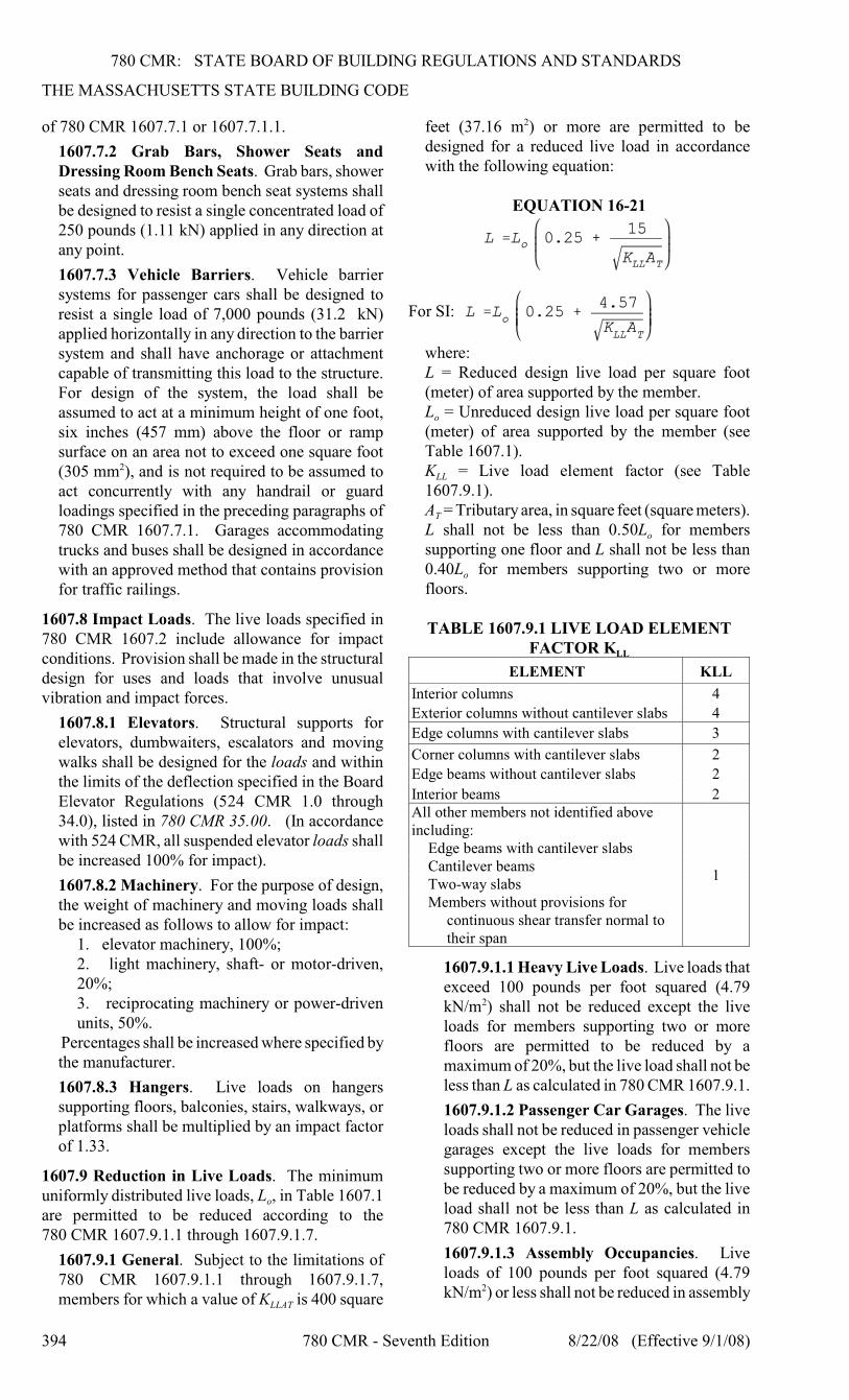
designed for a reduced live load in accordancewith the following equation:
EQUATION 16-21
For SI:
where:L = Reduced design live load per square foot(meter) of area supported by the member.
oL = Unreduced design live load per square foot(meter) of area supported by the member (seeTable 1607.1).
LLK = Live load element factor (see Table1607.9.1).
TA = Tributary area, in square feet (square meters).
oL shall not be less than 0.50L for memberssupporting one floor and L shall not be less than
o0.40L for members supporting two or morefloors.
TABLE 1607.9.1 LIVE LOAD ELEMENT
LLFACTOR K
ELEMENT KLL
Interior columns 4
Exterior columns without cantilever slabs 4
Edge columns with cantilever slabs 3
Corner columns with cantilever slabs 2
Edge beams without cantilever slabs 2
Interior beams 2All other members not identified aboveincluding:
1
Edge beams with cantilever slabsCantilever beamsTwo-way slabsMembers without provisions for
continuous shear transfer normal totheir span
1607.9.1.1 Heavy Live Loads. Live loads thatexceed 100 pounds per foot squared (4.79kN/m ) shall not be reduced except the live2
loads for members supporting two or morefloors are permitted to be reduced by amaximum of 20%, but the live load shall not beless than L as calculated in 780 CMR 1607.9.1.
1607.9.1.2 Passenger Car Garages. The liveloads shall not be reduced in passenger vehiclegarages except the live loads for memberssupporting two or more floors are permitted tobe reduced by a maximum of 20%, but the liveload shall not be less than L as calculated in780 CMR 1607.9.1.
1607.9.1.3 Assembly Occupancies. Liveloads of 100 pounds per foot squared (4.79kN/m ) or less shall not be reduced in assembly2
780 CMR: STATE BOARD OF BUILDING REGULATIONS AND STANDARDS
STRUCTURAL DESIGN
8/22/08 (Effective 9/1/08) 780 CMR - Seventh Edition 395
occupancies, except that the live loads formembers supporting two or more floors arepermitted to be reduced by a maximum of 20%,but the live load shall not be less than L ascalculated in 780 CMR 1607.9.1.
1607.9.1.4 Special Structural Elements. Liveloads shall not be reduced for one-way slabsexcept as permitted in 780 CMR 1607.9.1.1.Live loads of 100 pound per foot squared (4.79kN/m ) or less shall not be reduced for roof2
members except as specified in 780 CMR1607.11.2.
1607.9.1.5 Hangers. Live load shall not bereduced for hangers.
1607.9.1.6 Open Web Steel Joists. Live loadshall not be reduced for open web steel barjoists.
1607.9.1.7 Concrete Flat Slabs and Plates.Live load shall not be reduced for peripheral(two-way action) shear around columns,capitals, and drop panels of concrete flat slabs,flat plates, and grid slabs.
1607.10 Distribution of Floor Loads. Whereuniform floor live loads are involved in the design ofstructural members arranged so as to createcontinuity, the minimum applied loads shall be thefull dead loads on all spans in combination with thefloor live loads on spans selected to produce thegreatest effect at each location under consideration.It shall be permitted to reduce floor live loads inaccordance with 780 CMR 1607.9.
1607.11 Roof Loads. The structural supports ofroofs and marquees shall be designed to resist windand, where applicable, snow and earthquake loads, inaddition to the dead load of construction and theappropriate live loads as prescribed in this780 CMR, or as set forth in Table 1607.1. The liveloads acting on a sloping surface shall be assumed toact vertically on the horizontal projection of thatsurface.
1607.11.1 Distribution of Roof Loads. Whereuniform roof live loads are involved in the designof structural members arranged so as to createcontinuity, the minimum applied loads shall be thefull dead loads on all spans in combination withthe roof live loads on adjacent spans or onalternate spans, whichever produces the greatesteffect. See 780 CMR 1607.11.2 for minimumroof live loads and ASCE 7, Section 7.5 for partialsnow loading.
1607.11.2 Minimum Roof Live Loads.Minimum roof loads shall be determined for thespecific conditions in accordance with 780 CMR1607.11.2.1 through 1607.11.2.5.
1607.11.2.1 Flat, Pitched and Curved Roofs.Ordinary flat, pitched and curved roofs shall bedesigned for the live loads specified in the
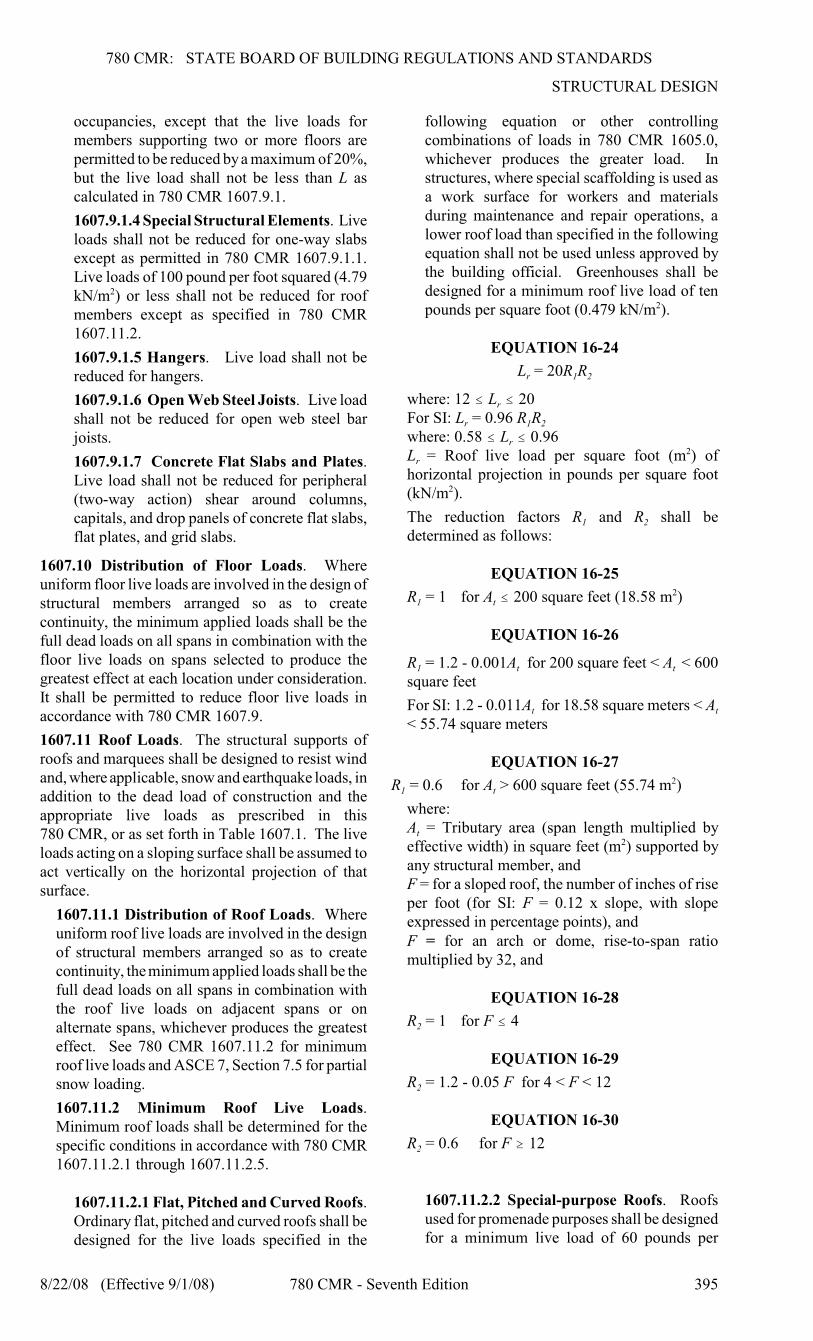
following equation or other controllingcombinations of loads in 780 CMR 1605.0,whichever produces the greater load. Instructures, where special scaffolding is used asa work surface for workers and materialsduring maintenance and repair operations, alower roof load than specified in the followingequation shall not be used unless approved bythe building official. Greenhouses shall bedesigned for a minimum roof live load of tenpounds per square foot (0.479 kN/m ).2
EQUATION 16-24
r 1 2L = 20R R
rwhere: 12 # L # 20
r 1 2For SI: L = 0.96 R R
rwhere: 0.58 # L # 0.96
r L = Roof live load per square foot (m ) of2
horizontal projection in pounds per square foot(kN/m ).2
1 2The reduction factors R and R shall bedetermined as follows:
EQUATION 16-25
1 tR = 1 for A # 200 square feet (18.58 m )2
EQUATION 16-26
1 t t R = 1.2 - 0.001A for 200 square feet < A < 600square feet
t tFor SI: 1.2 - 0.011A for 18.58 square meters < A< 55.74 square meters
EQUATION 16-27
1 tR = 0.6 for A > 600 square feet (55.74 m )2
where:
tA = Tributary area (span length multiplied byeffective width) in square feet (m ) supported by2
any structural member, andF = for a sloped roof, the number of inches of riseper foot (for SI: F = 0.12 x slope, with slopeexpressed in percentage points), andF = for an arch or dome, rise-to-span ratiomultiplied by 32, and
EQUATION 16-28
2R = 1 for F # 4
EQUATION 16-29
2R = 1.2 - 0.05 F for 4 < F < 12
EQUATION 16-30
2R = 0.6 for F $ 12
1607.11.2.2 Special-purpose Roofs. Roofsused for promenade purposes shall be designedfor a minimum live load of 60 pounds per
780 CMR: STATE BOARD OF BUILDING REGULATIONS AND STANDARDS
THE MASSACHUSETTS STATE BUILDING CODE
396 780 CMR - Seventh Edition 8/22/08 (Effective 9/1/08)
square foot (2.87 kN/m ). Roofs used for roof2
gardens or assembly purposes shall be designedfor a minimum live load of 100 pounds persquare foot (4.79 kN/m ). Roofs used for other2
special purposes shall be designed forappropriate loads, as directed or approved bythe building official.
1607.11.2.3 Landscaped Roofs. Where roofsare to be landscaped, the uniform design liveload in the landscaped area shall be 20 poundsper square foot (0.958 kN/m ). The weight of2
the landscaping materials shall be consideredas dead load and shall be computed on thebasis of saturation of the soil.
1607.11.2.4 Awnings and Canopies.Awnings and canopies shall be designed for auniform live load of five pounds per squarefoot (0.240 kN/m ) as well as for snow loads2
and wind loads as specified in 780 CMR1608.0 and 1609.0.
1607.11.2.5 Cornices and OverhangingEaves. Cornices, overhanging eaves and othersimilar projections shall be designed for aminimum uniform load of 60 pounds persquare foot or a load of 100 pounds per linealfoot of projection, whichever gives the mostsevere structural effect. The linear load shallbe positioned to maximize the variousstructural effects.
1607.12 Crane Loads. The crane live load shall bethe rated capacity of the crane. Design loads for therunway beams, including connections and supportbrackets, of moving bridge cranes and monorailcranes shall include the maximum wheel loads of thecrane and the vertical impact, lateral, andlongitudinal forces induced by the moving crane.
1607.12.1 Maximum Wheel Load. Themaximum wheel loads shall be the wheel loadsproduced by the weight of the bridge, asapplicable, plus the sum of the rated capacity andthe weight of the trolley with the trolleypositioned on its runway at the location where theresulting load effect is maximum.
1607.12.2 Vertical Impact Force. The maximumwheel loads of the crane shall be increased by thepercentages shown below to determine theinduced vertical impact or vibration force:
Monorail cranes (powered) 25%Cab-operated or remotely operated
bridge cranes (powered) 25%Pendant-operated bridge cranes
(powered) 10%Bridge cranes or monorail cranes
with hand-geared bridge, trolley and hoist 0%
1607.12.3 Lateral Force. The lateral force on
crane runway beams with electrically poweredtrolleys shall be calculated as 20% of the sum ofthe rated capacity of the crane and the weight ofthe hoist and trolley. The lateral force shall beassumed to act horizontally at the traction surfaceof a runway beam, in either direction perpendicu-lar to the beam, and shall be distributed accordingto the lateral stiffness of the runway beam andsupporting structure.
1607.12.4 Longitudinal Force. The longitudinalforce on crane runway beams, except for bridgecranes with hand-geared bridges, shall be calcu-lated as 10% of the maximum wheel loads of thecrane. The longitudinal force shall be assumed toact horizontally at the traction surface of a runwaybeam, in either direction parallel to the beam.
1607.13 Interior Walls and Partitions. Interiorwalls and partitions, including their finish materials,shall have adequate strength to resist the loads towhich they are subjected but not less than ahorizontal load of five pounds per square foot (0.240kN/m ). Self-supporting portable partitions used in2
office furnishings are exempt from this requirement.
780 CMR 1608.0 SNOW LOADS780 CMR 1608.0 is unique to Massachusetts
1608.1 General. Design snow loads shall bedetermined in accordance with ASCE 7, Section 7,except as provided otherwise in 780CMR 1608.0.The design roof load shall not be less than thatdetermined by 780 CMR 1607.0.
1608.2 Ground Snow Loads. Disregard ASCE 7,Section 7.2, Figure 7.1, and Table 7-1. Ground snow
gloads, p , to be used in the determination of designsnow loads for roofs and other surfaces exposed tosnow shall be as set forth in 780 CMR 1604.10.1608.3 Convex Curved Roofs. ASCE 7, Section7.4.3 applies to convex curved roofs only. See780 CMR 1608.4 for concave curved roofs.
1608.4 Concave Curved Roofs. The effectiveloaded area of a concave curved roof shall be thatarea of the surface of the roof where the tangents tothe surface have a slope of 50 degrees or less. Thetotal uniform snow load for concave curved roofs
ƒshall be the basic snow load, P , multiplied by thetotal horizontal projected area of the roof. This totalload shall be applied uniformly over the effectiveloaded area of the roof.
1608.5 Drifts on Lower Roofs.
1608.5.1 Width of Windward drifts. The widthof drift, w, in Figure 7-8 of ASCE 7, shall be eight
d ctimes the height of the drift (8 times h or h asapplicable) for all windward drifts.
780 CMR: STATE BOARD OF BUILDING REGULATIONS AND STANDARDS
STRUCTURAL DESIGN
8/22/08 (Effective 9/1/08) 780 CMR - Seventh Edition 397
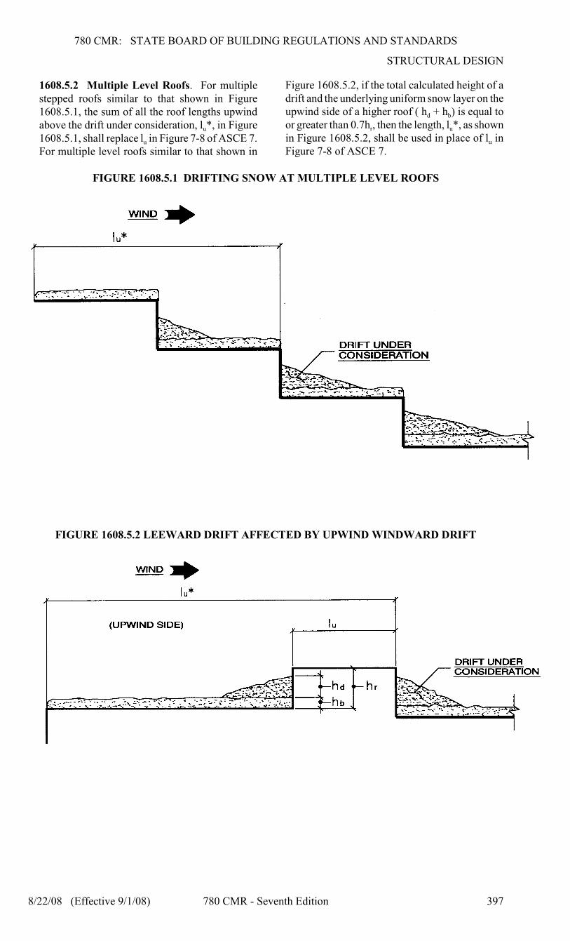
1608.5.2 Multiple Level Roofs. For multiplestepped roofs similar to that shown in Figure1608.5.1, the sum of all the roof lengths upwind
uabove the drift under consideration, l *, in Figure
u1608.5.1, shall replace l in Figure 7-8 of ASCE 7.For multiple level roofs similar to that shown in
Figure 1608.5.2, if the total calculated height of adrift and the underlying uniform snow layer on the
d bupwind side of a higher roof ( h + h ) is equal to
r uor greater than 0.7h , then the length, l *, as shown
uin Figure 1608.5.2, shall be used in place of l inFigure 7-8 of ASCE 7.
FIGURE 1608.5.1 DRIFTING SNOW AT MULTIPLE LEVEL ROOFS
FIGURE 1608.5.2 LEEWARD DRIFT AFFECTED BY UPWIND WINDWARD DRIFT
780 CMR: STATE BOARD OF BUILDING REGULATIONS AND STANDARDS
THE MASSACHUSETTS STATE BUILDING CODE
398 780 CMR - Seventh Edition 8/22/08 (Effective 9/1/08)
1608.5.3 Very High Roof Separations. When
r T Tthe ratio h /L is greater than 1.0, where L is thedimension in feet of the upper roof perpendicular
uto the wind flow (perpendicular to l in Figure 7-8of ASCE 7), the drift surcharge load on the lowerroof due to drifting of snow from the upper roofmay be reduced. The reduced height of the drift
drsurcharge, h , shall be not less than:
dr r r Th = h (2 - h /L )
r T drexcept that when h /L is greater than 2.0, h shallbe equal to zero.
1608.5.4 Intersecting Drifts. Where there aredrifts at walls intersecting at an angle, the unitsnow load at any point on the lower roof shall benot less than the greater of the unit loads from thetwo individual drift surcharges, plus the unit loadof the balanced snow load.
1608.5.5 Snow Pockets or Wells. Account shallbe taken of the load effects of potentiallyexcessive snow accumulation in pockets or wellsof roofs or decks.
1608.6 Roof Projections. The term roof projectionsused in 780 CMR and In ASCE 7, Section 7.8 shallbe interpreted to include screen walls, parapets, firewall projections, and mechanical equipment. Driftloads at roof projections shall be in accordance withASCE 7, Section 7.8, except that the width of drift
dshall be 8 times the height of the drift (eight times h
cor h in Figure 7-8, as applicable).
1608.7 Sliding Snow. In addition to the slidingsnow load on a lower roof as required in ASCE 7,Section 7.9, the lower roof shall be designed for awindward drift surcharge at the wall separating theupper and lower roofs in accordance with 780 CMR1608.5.1 and ASCE 7, Section 7.8. The slidingsnow load and the windward drift surcharge need notbe considered to act concurrently.
1608.7.1 Snow Guards. Sliding snow from anadjacent sloping high roof need not be consideredon the low roof if snow guards, as specified in780 CMR 1608.7.1, are provided on the high roof.In this case, the sloping roof with snow guardsshall be designed for the unit snow loads requiredfor a flat roof. Snow guards shall be designed bya registered design professional (RDP) qualifiedin the structural design of buildings. The designof the snow guards shall be shown on theconstruction documents. The RDP shall insurethat there are adequate load paths from the snowguards into the supporting members and from thesupporting members into the structure. Thestructural design of snow guards shall account forthe impact of the sliding snow. The effectivenessin preventing the sliding of snow of proprietarysnow guard systems shall be demonstrated bytests.
1608.8 Snow Storage and Collection Areas.Consideration of potentially excessive snow
accumulation shall be given to portions of structuresdesignated or used as snow collection or storageareas during and after snow removal operations (e.g.temporary snow collection areas when mechanicallyremoving snow from a roof; snow storage areas forparking structures).
780 CMR 1609 WIND LOADS780 CMR 1609.0 is unique to Massachusetts
1609.1 General. Design wind loads shall bedetermined from ASCE 7, Section 6 except asprovided otherwise in 780 CMR 1609.0.
1609.1.1 Limit to Wind Tunnel Procedure.Wind loads determined in accordance withASCE 7, section 6.6 (Method 3) shall have alower bound of b of the wind loads determinedfor Exposure B in accordance with ASCE 7,Section 6.5 (Method 2).
1609.2 Basic Wind Speed and WindDirectionality Factor.
1609.2.1 Basic Wind Speed. In ASCE 7,disregard the body of the text after the sectionnumber and title of Section 6.5.4, disregardSubsection 6.5.4.1, and disregard Figure 6-1. Thebasic wind speed, V, used in the determination ofdesign wind loads on buildings and otherstructures shall be as given in 780 CMR 1604.10,except as provide in 780 CMR 1609.2.2. V is thenominal three-second gust wind speed in milesper hour at 33 feet (10 m) above ground forExposure C category. The wind shall be assumedto come from any horizontal direction.
1609.2.2 Estimation of Basic Wind Speedsfrom Regional Climatic Data. In ASCE 7,Subsection 6.5.4.2, replace “Fig. 6-1” wherever itoccurs with “780 CMR 1604.10”.
1609.3 Anchorage Against Overturning, Upliftand Sliding. Structural members and systems, andcomponents and cladding in a building or structureshall be anchored to resist wind-induced overturning,uplift and sliding and to provide continuous loadpaths for these forces to the foundation. Where aportion of the resistance to these forces is providedby dead load, the dead load, including the weight ofsoils and foundations, shall be taken as the minimumdead load likely to be in place during a design windevent.
1609.4 Wind and Seismic Detailing. Lateral-force-resisting systems shall meet seismic detailingrequirements and limitations prescribed in780 CMR, even when wind code prescribed loadeffects are greater than seismic load effects.
1609.5 Enclosure Classifications. Replace ASCE7, Section 6.5.9.3 with 780 CMR 1609.5.1.
1609.5.1 Protection of Openings. In wind-bornedebris regions, glazing in the lower 60 feet (18288 mm) in buildings shall be assumed to be
780 CMR: STATE BOARD OF BUILDING REGULATIONS AND STANDARDS
STRUCTURAL DESIGN
8/22/08 (Effective 9/1/08) 780 CMR - Seventh Edition 399
openings unless such glazing is impact resistant orprotected with an impact-resistant coveringmeeting the requirements of an approved impact-resisting standard or ASTM E 1996 and of ASTME 1886 referenced 780 CMR as follows:
1. Glazed openings located within 30 feet(9144 mm) of grade shall meet therequirements of the Large Missile Test ofASTM E 1996.2. Glazed openings located more than 30 feet(9144 mm) above grade shall meet theprovisions of the Small Missile Test of ASTME 1996.
Exception. Wood structural panels with a
16minimum thickness of / inch (11.1 mm)7
and maximum panel span of eight feet (2438mm) shall be permitted for openingprotection in one- and two-story buildings.Panels shall be precut to cover the glazedopenings with attachment hardwareprovided. Attachments shall be designed toresist the components and cladding loadsdetermined in accordance with theprovisions of 780 CMR 1609.6.5.Attachment in accordance with Table1609.5.1 is permitted for buildings with amean roof height of 33 feet (10 058 mm) orless where wind speeds (three-second gust)do not exceed 130 miles per hour.
TABLE 1609.5.1 WINDBORN DEBRISPROTECTION FASTENING SCHEDULEFOR WOOD STRUCTURAL PANELSa, b, c
FASTENER
TYPE
FASTENER SPACING (inches)
Panel
span # 2
feet
2 feet #Panel span
# 4 feet
4 feet <
Panel span
# 6 feet
6 feet <
Panel span
# 8 feet
2½ # 6 Wood
Screws16 16 12 9
2½ # 6 Wood
Screws16 16 16 12
For SI: 1 inch = 25.4 mm, 1 foot = 304.8 mm, 1 pound =0.454 kg, 1 mile per hour = 0.44 m/s.a. Table 1609.5.1 is based on a maximum wind speed
(three-second gust) of 130 mph and mean roof heightof 33 feet or less.
b. Fasteners shall be installed at opposing ends of thewood structural panel.
c. Where screws are attached to masonry ormasonry/stucco, they shall be attached utilizingvibration-resistant anchors having a minimum
withdrawal capacity of 490 pounds.
1609.6 Rigid Tile Roof Coverings. Rigid tile roofcoverings that are air-permeable are permitted to bedesigned in accordance with 780 CMR 1609.6.1
1609.6.1 Wind loads on air permeable rigid tile roofcoverings may be determined in accordance with thefollowing equation:
EQUATION 16-36
a h L a pM = q C bLL [1.0 - Gc ]
where: b = Exposed width feet (m) of the roof tile.
LC = Lift coefficient. The lift coefficient forconcrete and clay tile shall be 0.2 or shall bedetermined by test in accordance with 780 CMR1715.2.
cpG = Roof pressure coefficient for each applicableroof zone determined from ASCE 7, Section 6.Roof coefficients shall not be adjusted for internalpressure.L = Length feet (m) of the roof tile.
aL = Moment arm feet (m) from the axis ofrotation to the point of uplift on the roof tile. Thepoint of uplift shall be taken at 0.76L from thehead of the tile and the middle of the exposedwidth. For roof tiles with nails or screws (with orwithout a tail clip), the axis of rotation shall betaken as the head of the tile for direct deckapplication or as the top edge of the batten forbattened applications. For roof tiles fastened onlyby a nail or screw along the side of the tile, theaxis of rotation shall be determined by testing.For roof tiles installed with battens and fastenedonly by a clip near the tail of the tile, the momentarm shall be determined about the top edge of thebatten with consideration given for the point ofrotation of the tiles based on straight bond orbroken bond and the tile profile.
aM = Aerodynamic uplift moment feet-pounds(kN-m) acting to raise the tail of the tile.
hq = Wind velocity pressure psf (kN/m )2
determined from ASCE 7, Section.
Concrete and clay roof tiles complying with thefollowing limitations shall be designed towithstand the aerodynamic uplift moment asdetermined by 780 CMR 1609.6.
1. The roof tiles shall be either loose laid onbattens, mechanically fastened, mortar set oradhesive set.2. The roof tiles shall be installed on solidsheathing which has been designed ascomponents and cladding.3. An underlayment shall be installed inaccordance with 780 CMR 15.00.4. The tile shall be single lapped interlockingwith a minimum head lap of not less than twoinches (51 mm).5. The length of the tile shall be between 1.0and 1.75 feet (305 mm and 533 mm).6. The exposed width of the tile shall bebetween 0.67 and 1.25 feet (204 mm and 381mm).7. The maximum thickness of the tail of thetile shall not exceed 1.3 inches (33 mm).8. Roof tiles using mortar set or adhesive setsystems shall have at least b of the tile’s areafree of mortar or adhesive contact.
780 CMR: STATE BOARD OF BUILDING REGULATIONS AND STANDARDS
THE MASSACHUSETTS STATE BUILDING CODE
400 780 CMR - Seventh Edition 8/22/08 (Effective 9/1/08)
780 CMR 1610.0 LATERAL SOIL AND
HYDROSTATIC LOADS780 CMR 1610.0 is unique to Massachusetts
1610.1 General. Basement, foundation, andretaining walls shall be designed to resist lateralloads due to soil and water pressure. Lateral soilpressure on said walls shall be determined inaccordance with the principles of soil mechanics andas provided in 780 CMR 18.00. Floors or similarelements below the water table shall be designed toresist the upward pressure of the water.
Exception. Uninhabitable spaces with concretefloors on the ground with an under-slab drainagesystem, including sump pits and sump pumps,designed to keep the water level a minimum ofone foot below the bottom of the floor slab neednot be designed to resist water pressure.
780 CMR 1611.0 RAIN LOADS
1611.1 Design Rain Loads. Each portion of a roofshall be designed to sustain the load of rainwater thatwill accumulate on it if the primary drainage systemfor that portion is blocked plus the uniform loadcaused by water that rises above the inlet of thesecondary drainage system at its design flow.
EQUATION 16-37
s hR = 5.2 (d + d )
s hFor SI: R = 0.0098 (d + d ) where:
hd = Additional depth of water on the undeflectedroof above the inlet of secondary drainage systemat its design flow (i.e., the hydraulic head), ininches (mm).
sd = Depth of water on the undeflected roof up tothe inlet of secondary drainage system when theprimary drainage system is blocked (i.e., the statichead), in inches (mm).R = Rain load on the undeflected roof, in poundsper square foot (kN/m ). When the phrase2
“undeflected roof” is used, deflections from loads(including dead loads) shall not be consideredwhen determining the amount of rain on the roof.
1611.2 Ponding Instability. Ponding refers to theretention of water due solely to the deflection ofrelatively flat roofs. Roofs with a slope less thanone-fourth unit vertical in 12 units horizontal (2%slope) shall be investigated by structural analysis toensure that they possess adequate stiffness topreclude progressive deflection (i.e., instability) asrain falls on them or meltwater is created from snowon them. The larger of snow load or rain load shallbe used in this analysis. The primary drainagesystem within an area subjected to ponding shall beconsidered to be blocked in this analysis.
1611.3 Controlled Drainage. Roofs equipped withhardware to control the rate of drainage shall beequipped with a secondary drainage system at a
higher elevation that limits accumulation of water onthe roof above that elevation. Such roofs shall bedesigned to sustain the load of rainwater that willaccumulate on them to the elevation of the secondarydrainage system plus the uniform load caused bywater that rises above the inlet of the secondarydrainage system at its design flow determined from780 CMR 1611.1. Such roofs shall also be checkedfor ponding instability in accordance with 780 CMR1611.2.
780 CMR 1612.0 FLOOD LOADS780 CMR 1612.0 is unique to Massachusetts
1612.1 General. Flood loads shall be determined inaccordance with ASCE 7, Section 5.3. Design andconstruction in flood zones shall be in accordancewith ASCE 24 and 780 CMR 120.G and the morestringent design and construction requirements ofASCE 24 or 780 CMR 120.G , as applicable (“rightto construct and structure allowed/required eleva-tions shall be governed by the last sentence of780 CMR 1612.1), shall be expressly identified atthe building permit application stage and the morestringent requirements of either reference shallgovern, except that flood loads shall be inaccordance with the issue of ASCE 7 cited in780 CMR 35.00 and “right-to construct” and struc-ture-allowed elevations shall be governed by 780CMR 120.G, M.G.L. c. 131, § 40 and any bylaws orordinances that have legal standing in a community.
780 CMR 1613.0 EARTHQUAKE LOADS
– PURPOSE
780 CMR 1613.0 through 1615.0 present criteriafor the design and construction of buildings andnonbuilding structures subject to earthquake groundmotion. The specified earthquake loads rely on post-elastic energy dissipation in the structure, andbecause of this fact, the provisions for design,detailing and construction shall be satisfied even forstructures and members for which load combinationscontaining earthquake load produce lesser effectsthan other load combinations.
The purposes of 780 CMR 1613.0 through 1615.0are to minimize the hazard to life of occupants of allbuildings and nonbuilding structures, to increase theexpected performance of high occupancy assemblyand education buildings as compared to ordinarybuildings, and to improve the capability of essentialfacilities to function during and after an earthquake.Because of the complexity of and the great numberof variables involved in seismic design (e.g.variability in ground motion, soil types, dynamiccharacteristics of the structure, material strengthproperties and construction practices), 780 CMR1613.0 through 1615.0 present only minimumcriteria in general terms. These minimum criteria areconsidered to be prudent and economically justifiedfor the protection of life safety in buildings subjectto earthquakes and for improved capability of
780 CMR: STATE BOARD OF BUILDING REGULATIONS AND STANDARDS
STRUCTURAL DESIGN
8/22/08 (Effective 9/1/08) 780 CMR - Seventh Edition 401
essential facilities to function immediately followingan earthquake.
Absolute safety and prevention of damage, even inan earthquake event with a reasonable probability ofoccurrence, cannot be achieved economically formost buildings. The “design earthquake” groundmotion levels specified in 780 CMR may result inboth structural and non-structural damage. For mostbuildings designed and constructed according to780 CMR 1613.0 through 1615.0, it is expected thatstructural damage from a major earthquake may berepairable but the repair may not be economicallyfeasible. For ground motions larger than the designlevels, the intent of 780 CMR 1613.0 through 1615.0is that there will be a low likelihood of buildingcollapse.
780 CMR 1614.0 EARTHQUAKE LOADS
– GENERAL
1614.1 Scope. Every building and portion thereof,and certain nonbuilding structures as provided780 CMR 1614.0 shall as a minimum be designedand constructed to resist the effects of earthquakemotions and assigned a seismic design category asset forth in 780 CMR 1614.0
Exceptions:1. Detached one- and two-family dwellings areexempt from the requirements of these provisions.2. Agricultural storage buildings that areintended only for incidental human occupancy areexempt from the requirements of these provisions.3. Additions to existing buildings. An additionthat is attached to an existing building shall bedesigned and constructed in accordance with therequirements of 780 CMR 34.00. Structurallyseparate additions shall be designed andconstructed in accordance with 780 CMR 16.00.4. Change of occupancy: Where a change ofoccupancy occurs in an existing building, thebuilding shall conform to the provisions of780 CMR 34.00.5. Alterations. Where alterations are made to anexisting building, the building shall conform tothe provisions of 780 CMR 34.00.6. Special structures including, but not limitedto, vehicular bridges, transmission towers,hydraulic structures, and nuclear power generatingfacilities shall be designed to resist earthquakeloads, but require special consideration of theirresponse characteristics and environment that isbeyond the scope of 780 CMR 1614.0.Structures shall be designed in accordance with
ASCE 7. Only the following sections, as modifiedin 780 CMR 1614.0, shall apply: 9.1.2.4, 9.1.2.5,9.1.3, 9.1.4, 9.2 through 9.6, 9.13, and 9.14. Withinthe above-noted sections, all references to Sections9.7 through 9.12 shall be revised as follows:
ASCE 7MASS STATE BUILDING
CODE
9.7 Foundation Design
Requirements
780 CMR 18.00 Soils and
Foundations
9.8 Steel 780 CMR 22.00 Steel
9.9 Structural Concrete 780 CMR 19.00 Concrete
9.10 Composite Structure (Not Applicable)
9.11 Masonry 780 CMR 21.00 Masonry
9.12 Wood 780 CMR 23.00 Wood
Appendices A.9 and B.0 of ASCE 7 are notapplicable.
1614.2 Additions to Existing Buildings. Seeprovisions of 780 CMR 34.00, except that 780 CMR16.00 applies to structurally separate additions.
1614.3 Quality Assurance. A Quality AssurancePlan shall be provided where required by 780 CMR17.00.
780 CMR 1615.0 EARTHQUAKE LOADS
– MODIFICATIONS TO APPLICABLE
PROVISIONS OF ASCE 7(Note that the following subsections, commencingwith the prefix number “9” are referring toapplicable sections of ASCE 7).
1615.1 Changes to Applicable ASCE 7 Sections.The provisions of ASCE 7, Sections 9.1.2.4, 9.1.2.5,9.1.3, 9.1.4, 9.2 through 9.6, 9.13 and 9.14 and allassociated sub-sections shall apply except for certainparagraphs of those sections and sub-sections whichhave been modified or added as provided below:
9.1.2.4.1 New Buildings. New buildings andstructures shall be designed and constructed inaccordance with the quality assurancerequirements of 780 CMR 17.00. The analysisand design of structural systems and components,including foundations, frames, walls, floors androofs shall be in accordance with the applicablerequirements of Section 9.5. The additionalfoundation requirements of 780 CMR 18.00 shallbe followed. Materials used in construction andcomponents made of these materials shall bedesigned and constructed to meet the requirementsof 780 CMR 19.00 through 23.00. Architectural,electrical and mechanical systems andcomponents, including tenant improvements, shallbe designed in accordance with Section 9.6.
9.2.1 Definitions. The definitions presented in thisSection provide the meaning of the terms used inthese provisions. Definitions of terms that have aspecific meaning relative to the use of concrete,masonry, steel or wood are presented in the Chapterdevoted to the material (780 CMR 19.00, 21.00,22.00 and 23.00). Disregard ASCE 7 references tonon-applicable Sections and Appendix A9. (Note:See ASCE 7, Section 9.2.1 for definitions.)
780 CMR: STATE BOARD OF BUILDING REGULATIONS AND STANDARDS
THE MASSACHUSETTS STATE BUILDING CODE
402 780 CMR - Seventh Edition 8/22/08 (Effective 9/1/08)
9.2.2 Symbols. The unit dimensions used with theitems covered by the symbols shall be consistentthroughout except where specifically noted. Thesymbols and definitions presented in this Sectionapply to these provisions as indicated, except thatreferences to A9.8 apply to 780 CMR 22.00 andreferences to A9.9 apply to 780 CMR 19.00. (Note:See ASCE 7, Section 9.2.2 for symbols.)
SECTION 9.4 – Site Ground Motion
9.4.1 Procedures for Determining MaximumConsidered Earthquake and Design EarthquakeGround Motion Accelerations and ResponseSpectra. Ground motion accelerations, representedby response spectra and coefficients derived fromthese spectra, shall be determined in accordance withthe general procedure of Section 9.4.1.2 or the site-specific procedure of Section 9.4.1.3. The generalprocedure in which spectral response accelerationparameters for the maximum considered earthquakeground motions are derived using Table 1604.10 ofthe Massachusetts State Building Code, modified bysite coefficients to include local site effects andscaled to design values, are permitted to be used forany structure except as specifically indicated in theseprovisions. The site-specific procedure also ispermitted to be used for any structure and shall beused where specifically required by these provisions.
9.4.1.1 Maximum Considered EarthquakeGround Motions. The maximum consideredearthquake ground motions shall be as representedby the spectral response acceleration at short
s 1periods (S ) and at 1-sec (S ) obtained from Table1604.10 of the Massachusetts State Building Codeand adjusted for Site Class effects using the sitecoefficients of Section 9.4.1.2.4. When a site-specific procedure is used, maximum consideredearthquake ground motion shall be determined inaccordance with Section 9.4.1.3.
9.4.1.2 General Procedure for DeterminingMaximum Considered Earthquake and DesignSpectral Response Accelerations. The maximumconsidered earthquake spectral response acceleration
s 1at short periods (S ) and at 1-sec (S ) shall bedetermined from Table 1604.10 of the MassachusettsState Building Code based on the municipality inwhich the site is located. Where a site is located inmore than one municipality, the higher spectralresponse acceleration values shall be used.
For buildings and structures included in the scopeof this Standard as specified in Section 9.1.2.1, theSite Class shall be determined in accordance withSection 9.4.1.2.1. The maximum consideredearthquake spectral response accelerations adjusted
MS M1for Site Class effects, S andS , shall bedetermined in accordance with Section 9.4.1.2.4 and
DSthe design spectral response accelerations, S
D1andS , shall be determined in accordance withSection 9.4.1.2.5. The general response spectrum,when required by these provisions, shall be
determined in accordance with Section 9.4.1.2.6.
9.4.1.2.1 Site Class Definitions. The site shallbe classified as one of the following classes:
A = Hard rock with measured shear wavevelocity, > 5000ft/s (1500 m/s)
B = Rock with 2500 ft/s < #5000 ft/s (760
m/s < # 1500 m/s)
C = Very dense soil and soft rock with 1200ft/s # # 2500 ft/s (370 m/s # # 760
m/s) or or > 50 or $ 2000 psf (100
kPa)
D = Stiff soil with 600 ft/s # # 1200 ft/s
(180 m/s # # 370 m/s) or with 15 # or
# 50 or 1000 psf # # 2000 psf (50 kPa
# # 100 kPa)
E = A soil profile with < 600 ft/s (180
m/s) or any profile with more than 10 ft (3 m)of soft clay. Soft clay is defined as soil with Pl
u> 20, w $ 40%, and s < 500 psf (25 kPa)
F = Soils requiring site-specific evaluations:
1. Soils vulnerable to potential failure or collapseunder seismic loading such as liquefiable soils,quick and highly sensitive clays, collapsibleweakly cemented soils. Potential for liquefactionshall be evaluated in accordance with 780 CMR1804.6: Liquefaction.
Exception. None.
2. Peats and/or highly organic clays (H > 10 ft [3m] of peat and/or highly organic clay where H =thickness of soil).3. Very high plasticity clays (H > 25 ft [7.6 m]with PI > 75).4. Very thick soft/medium stiff clays (H>120 ft[37 m].
Exception. None.
The following standards are referenced fordetermining the seismic coefficients:
(a) ASTM. "Test Method for Penetration Testand Split-Barrel Sampling of Soils." ASTMD1586-84, 1984.(b) ASTM. "Test Method for Liquid Limit,Plastic Limit, and Plasticity Index of Soils."ASTM D4318-93, 1993.(c) ASTM. "Test Method for LaboratoryDetermination of Water (Moisture) Content ofSoil and Rock." ASTM D2216-92, 1992.(d) ASTM. "Test Method for UnconfinedCompressive Strength of Cohesive Soil."ASTM D2166-1991, 1991.(e) ASTM. "Test Method for Unconsolidated,Undrained Compressive Strength of CohesiveSoils in Triaxial Compression." ASTM D2850-87, 1987.
780 CMR: STATE BOARD OF BUILDING REGULATIONS AND STANDARDS
STRUCTURAL DESIGN
8/22/08 (Effective 9/1/08) 780 CMR - Seventh Edition 403
9.4.1.2.2 Steps for Classifying a Site. TheSite Class of a site shall be determined usingthe following steps:
Step 1: Check for the four categories ofSite Class F requiring site-specificevaluation. If the site corresponds to any ofthese categories, classify the site as SiteClass F and conduct a site-specificevaluation.
Exception. Refer to exception in Note ain Table 9.4.1.2.4a and in Table9.4.1.2.4b.
Step 2: Check for the existence of a totalthickness of soft clay > 10 ft (3 m) where a
usoft clay layer is defined by s < 500 psf (25kPa), w > 40%, and Pl > 20. If this criterionis satisfied, classify the site as Site Class E.
Step 3: Categorize the site using one of thefollowing three methods with , , and
computed in all cases as specified by the
definitions in Section 9.4.1.2.3.
a. The Method: Determine for
the top 100 ft (30m) of soil. Compare thevalue of with those given in Section
9.4.1.2 and Table 9.4.1.2 and assign thecorresponding Site Class.
for rock, Site Class B, shall be
measured on-site or estimated by ageotechnical engineer or engineeringgeologist/seismologist for competentrock with moderate fracturing andweathering. for softer and more
highly fractured and weathered rock shallbe measured on-site or shall be classifiedas Site Class C. The Classification ofhard rock, Site Class A, shall besupported by on-site measurements of
or on profiles of the same rock type in thesame formation with an equal or greaterdegree of weathering and fracturing.Where hard rock conditions are known tobe continuous to a depth of at least 100 ft
s(30 m), surficial measurements of v arenot prohibited from being extrapolated toassess .
b. The Method: Determine for the
top 100 ft (30 m) of soil. Compare the valueof with those given in Section 9.4.1.2 and
Table 9.4.1.2 and assign the correspondingSite Class.c. The Method: For cohesive soil
layers, determine for the top 100 ft (30
m) of soil. For cohesionless soil layers,determine for the top 100 ft (30 m) of
soil. Cohesionless soil is defined by a Pl <
20 where cohesive soil is defined by a Pl >20. Compare the values of and
with those given in Section 9.4.1.2 andTable 9.4.1.2 and assign the correspondingSite Class. When the and criteria
differ, assign the category with the softersoil (Site Class E soil is softer than D).d. When soil properties are not known insufficient detail to determine the site class,Site Class D shall be used unless thebuilding official determines that soils of SiteClass E or Site Class F are likely to bepresent at the site.e. The rock categories, Site Classes A andB, shall not be assigned to a site if there ismore than ten feet (3 m) of soil between therock surface and the bottom of the spreadfooting or mat foundation.
9.4.1.2.3 Definitions of Site ClassParameters. The definitions presented belowapply to the upper 100 ft (30 m) of the siteprofile. Profiles containing distinctly differentsoil and/or rock layers shall be subdivided intothose layers designated by a number that rangesfrom 1 to n at the bottom where there are atotal of n distinct layers in the upper 100 ft (30m). Where some of the n layers are cohesiveand others are not, k is the number of cohesivelayers and m is the number of cohesionlesslayers. The symbol i refers to any one of thelayers between 1 and n.
siv is the shear wave velocity in ft/s (m/s).
id is the thickness of any layer between 0and 100 ft (30 m).
is EQUATION 9.4.1.2-1
whereby is equal to 100 ft (30 m)
1N is the standard penetration resistance,ASTM D156-84 not to exceed 100 blows/ftas directly measured on the field withoutcorrections. When refusal is met for a rocklayer, shall be taken as 100 blows/foot.
is EQUATION 9.4.1.2-2
i iwhere N and d in Equation 9.4.1.2-2 are forcohesionless soil, cohesive soil, and rocklayers.
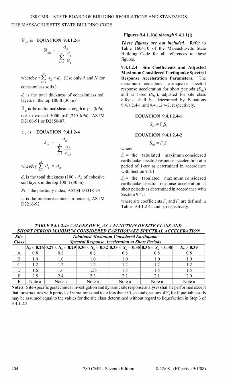
780 CMR: STATE BOARD OF BUILDING REGULATIONS AND STANDARDS
THE MASSACHUSETTS STATE BUILDING CODE
404 780 CMR - Seventh Edition 8/22/08 (Effective 9/1/08)
is EQUATION 9.4.1.2-3
s i iwhereby = = d . (Use only d and N for
cohesionless soils.)
sd is the total thickness of cohesionless soillayers in the top 100 ft (30 m)
is the undrained shear strength in psf (kPa),
not to exceed 5000 psf (240 kPa), ASTMD2166-91 or D2850-87.
is EQUATION 9.4.1.2-4
whereby .
c sd is the total thickness (100 - d ) of cohesivesoil layers in the top 100 ft (30 m)
Pl is the plasticity index, ASTM D4318-93
w is the moisture content in percent, ASTMD2216-92
Figures 9.4.1.1(a) through 9.4.1.1(j)
These figures are not included. Refer toTable 1604.10 of the Massachusetts StateBuilding Code for all references to thesefigures.
9.4.1.2.4 Site Coefficients and AdjustedMaximum Considered Earthquake SpectralResponse Acceleration Parameters. Themaximum considered earthquake spectral
MSresponse acceleration for short periods (S )
M1and at 1-sec (S ), adjusted for site classeffects, shall be determined by Equations9.4.1.2.4-1 and 9.4.1.2.4-2, respectively.
EQUATION 9.4.1.2.4-1
M1 a sS = F S
EQUATION 9.4.1.2.4-2
m1 v 1S = F Swhere
1S = the tabulated maximum consideredearthquake spectral response acceleration at aperiod of 1-sec as determined in accordancewith Section 9.4.1
sS = the tabulated maximum consideredearthquake spectral response acceleration atshort periods as determined in accordance withSection 9.4.1
a vwhere site coefficients F and F are defined inTables 9.4.1.2.4a and b, respectively.
aTABLE 9.4.1.2.4a VALUES OF F AS A FUNCTION OF SITE CLASS AND SHORT PERIOD MAXIMUM CONSIDERED EARTHQUAKE SPECTRAL ACCELERATION
SiteClass
Tabulated Maximum Considered EarthquakeSpectral Response Acceleration at Short Periods
S S S S S SS # 0.26 0.27 # S # 0.29 0.30 # S # 0.32 0.33 # S # 0.35 0.36 # S # 0.38 S $ 0.39A 0.8 0.8 0.8 0.8 0.8 0.8
B 1.0 1.0 1.0 1.0 1.0 1.0C 1.2 1.2 1.2 1.2 1.2 1.2D 1.6 1.6 1.55 1.5 1.5 1.5E 2.5 2.4 2.3 2.2 2.1 2.0F Note a Note a Note a Note a Note a Note a
Note a: Site-specific geotechnical investigation and dynamic site response analyses shall be performed except
athat for structures with periods of vibration equal to or less than 0.5-seconds, values of F for liquefiable soilsmay be assumed equal to the values for the site class determined without regard to liquefaction in Step 3 of9.4.1.2.2.
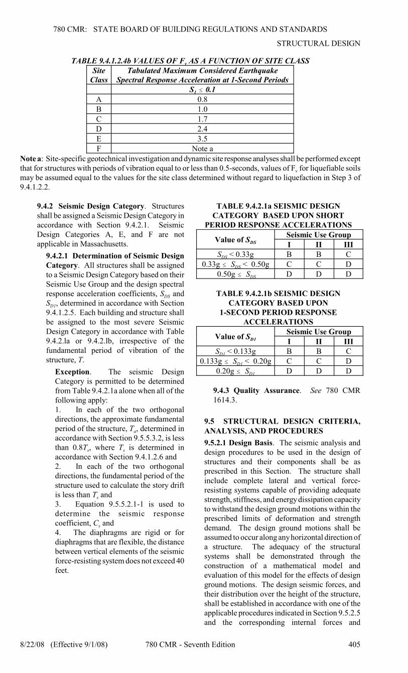
780 CMR: STATE BOARD OF BUILDING REGULATIONS AND STANDARDS
STRUCTURAL DESIGN
8/22/08 (Effective 9/1/08) 780 CMR - Seventh Edition 405
vTABLE 9.4.1.2.4b VALUES OF F AS A FUNCTION OF SITE CLASSSite
ClassTabulated Maximum Considered Earthquake
Spectral Response Acceleration at 1-Second Periods
1S # 0.1A 0.8B 1.0C 1.7D 2.4E 3.5F Note a
Note a: Site-specific geotechnical investigation and dynamic site response analyses shall be performed except
vthat for structures with periods of vibration equal to or less than 0.5-seconds, values of F for liquefiable soilsmay be assumed equal to the values for the site class determined without regard to liquefaction in Step 3 of9.4.1.2.2.
9.4.2 Seismic Design Category. Structuresshall be assigned a Seismic Design Category inaccordance with Section 9.4.2.1. SeismicDesign Categories A, E, and F are notapplicable in Massachusetts.
9.4.2.1 Determination of Seismic DesignCategory. All structures shall be assignedto a Seismic Design Category based on theirSeismic Use Group and the design spectral
DSresponse acceleration coefficients, S and
D1S , determined in accordance with Section9.4.1.2.5. Each building and structure shallbe assigned to the most severe SeismicDesign Category in accordance with Table9.4.2.la or 9.4.2.lb, irrespective of thefundamental period of vibration of thestructure, T.
Exception. The seismic DesignCategory is permitted to be determinedfrom Table 9.4.2.1a alone when all of thefollowing apply:1. In each of the two orthogonaldirections, the approximate fundamental
aperiod of the structure, T , determined inaccordance with Section 9.5.5.3.2, is less
s sthan 0.8T , where T is determined inaccordance with Section 9.4.1.2.6 and2. In each of the two orthogonaldirections, the fundamental period of thestructure used to calculate the story drift
sis less than T and3. Equation 9.5.5.2.1-1 is used todetermine the seismic response
scoefficient, C and4. The diaphragms are rigid or fordiaphragms that are flexible, the distancebetween vertical elements of the seismicforce-resisting system does not exceed 40feet.
TABLE 9.4.2.1a SEISMIC DESIGNCATEGORY BASED UPON SHORT
PERIOD RESPONSE ACCELERATIONS
DSValue of SSeismic Use GroupI II III
DSS < 0.33g B B C
DS0.33g # S < 0.50g C C D
DS 0.50g # S D D D
TABLE 9.4.2.1b SEISMIC DESIGNCATEGORY BASED UPON
1-SECOND PERIOD RESPONSEACCELERATIONS
D1Value of SSeismic Use GroupI II III
D1S < 0.133g B B C
D10.133g # S < 0.20g C C D
D10.20g # S D D D
9.4.3 Quality Assurance. See 780 CMR1614.3.
9.5 STRUCTURAL DESIGN CRITERIA,ANALYSIS, AND PROCEDURES
9.5.2.1 Design Basis. The seismic analysis anddesign procedures to be used in the design ofstructures and their components shall be asprescribed in this Section. The structure shallinclude complete lateral and vertical force-resisting systems capable of providing adequatestrength, stiffness, and energy dissipation capacityto withstand the design ground motions within theprescribed limits of deformation and strengthdemand. The design ground motions shall beassumed to occur along any horizontal direction ofa structure. The adequacy of the structuralsystems shall be demonstrated through theconstruction of a mathematical model andevaluation of this model for the effects of designground motions. The design seismic forces, andtheir distribution over the height of the structure,shall be established in accordance with one of theapplicable procedures indicated in Section 9.5.2.5and the corresponding internal forces and
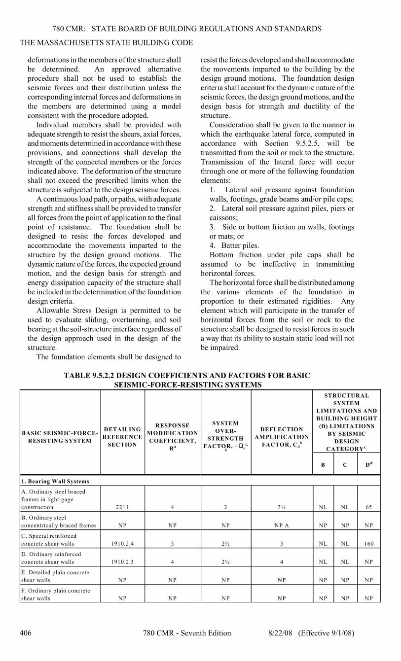
780 CMR: STATE BOARD OF BUILDING REGULATIONS AND STANDARDS
THE MASSACHUSETTS STATE BUILDING CODE
406 780 CMR - Seventh Edition 8/22/08 (Effective 9/1/08)
deformations in the members of the structure shallbe determined. An approved alternativeprocedure shall not be used to establish theseismic forces and their distribution unless thecorresponding internal forces and deformations inthe members are determined using a modelconsistent with the procedure adopted.
Individual members shall be provided withadequate strength to resist the shears, axial forces,and moments determined in accordance with theseprovisions, and connections shall develop thestrength of the connected members or the forcesindicated above. The deformation of the structureshall not exceed the prescribed limits when thestructure is subjected to the design seismic forces.
A continuous load path, or paths, with adequatestrength and stiffness shall be provided to transferall forces from the point of application to the finalpoint of resistance. The foundation shall bedesigned to resist the forces developed andaccommodate the movements imparted to thestructure by the design ground motions. Thedynamic nature of the forces, the expected groundmotion, and the design basis for strength andenergy dissipation capacity of the structure shallbe included in the determination of the foundationdesign criteria.
Allowable Stress Design is permitted to beused to evaluate sliding, overturning, and soilbearing at the soil-structure interface regardless ofthe design approach used in the design of thestructure.
The foundation elements shall be designed to
resist the forces developed and shall accommodatethe movements imparted to the building by thedesign ground motions. The foundation designcriteria shall account for the dynamic nature of theseismic forces, the design ground motions, and thedesign basis for strength and ductility of thestructure.
Consideration shall be given to the manner inwhich the earthquake lateral force, computed inaccordance with Section 9.5.2.5, will betransmitted from the soil or rock to the structure.Transmission of the lateral force will occurthrough one or more of the following foundationelements:
1. Lateral soil pressure against foundationwalls, footings, grade beams and/or pile caps;2. Lateral soil pressure against piles, piers orcaissons;3. Side or bottom friction on walls, footingsor mats; or 4. Batter piles.Bottom friction under pile caps shall be
assumed to be ineffective in transmittinghorizontal forces.
The horizontal force shall be distributed amongthe various elements of the foundation inproportion to their estimated rigidities. Anyelement which will participate in the transfer ofhorizontal forces from the soil or rock to thestructure shall be designed to resist forces in sucha way that its ability to sustain static load will notbe impaired.
TABLE 9.5.2.2 DESIGN COEFFICIENTS AND FACTORS FOR BASIC SEISMIC-FORCE-RESISTING SYSTEMS
BASIC SEISMIC-FORCE-
RESISTING SYSTEM
DETAILING
REFERENCE
SECTION
RESPONSE
MODIFICATION
COEFFICIENT,
Ra
SYSTEM
OVER-
STRENGTH
oFACTOR, !S c,
g
DEFLECTION
AMPLIFICATION
dFACTOR, C b
STRUCTURAL
SYSTEM
LIMITATIONS AND
BUILDING HEIGHT
(ft) LIMITATIONS
BY SEISMIC
DESIGN
CATEGORY c
B C Dd
1. Bearing Wall Systems
A. Ordinary steel braced
frames in light-gage
construction 2211 4 2 3½ NL NL 65
B. Ordinary steel
concentrically braced frames NP NP NP NP A NP NP NP
C. Special reinforced
concrete shear walls 1910.2.4 5 2½ 5 NL NL 160
D. Ordinary reinforced
concrete shear walls 1910.2.3 4 2½ 4 NL NL NP
E. Detailed plain concrete
shear walls NP NP NP NP NP NP NP
F. Ordinary plain concrete
shear walls NP NP NP NP NP NP NP
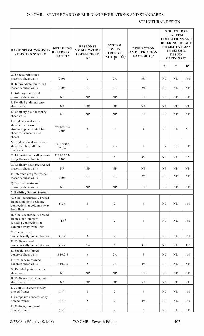
780 CMR: STATE BOARD OF BUILDING REGULATIONS AND STANDARDS
STRUCTURAL DESIGN
BASIC SEISMIC-FORCE-
RESISTING SYSTEM
DETAILING
REFERENCE
SECTION
RESPONSE
MODIFICATION
COEFFICIENT,
Ra
SYSTEM
OVER-
STRENGTH
oFACTOR, !S c,
g
DEFLECTION
AMPLIFICATION
dFACTOR, C b
STRUCTURAL
SYSTEM
LIMITATIONS AND
BUILDING HEIGHT
(ft) LIMITATIONS
BY SEISMIC
DESIGN
CATEGORY c
B C Dd
8/22/08 (Effective 9/1/08) 780 CMR - Seventh Edition 407
G. Special reinforced
masonry shear walls 2106 5 2½ 3½ NL NL 160
H. Intermediate reinforced
masonry shear walls 2106 3½ 2½ 2¼ NL NL NP
I. Ordinary reinforced
masonry shear walls NP NP NP NP NP NP NP
J. Detailed plain masonry
shear walls NP NP NP NP NP NP NP
K. Ordinary plain masonry
shear wallsNP NP NP NP NP NP NP
L. Light-framed walls
sheathed with wood
structural panels rated for
shear resistance or steel
sheets
2211/2305/
23066 3 4 NL NL 65
M. Light-framed walls with
shear panels of all other
materials
2211/2305
/23062 2½ 2 35 35 NP
N. Light-framed wall systems
using flat strap bracing
2211/2305/
23064 2 3½ NL NL 65
O. Ordinary plain prestressed
masonry shear walls NP NP NP NP NP NP NP
P. Intermediate prestressed
masonry shear walls 21062½ 2½ 2½ NL NP NP
Q. Special prestressed
masonry shear walls NP NP NP NP NP NP NP
2. Building Frame Systems
A. Steel eccentrically braced
frames, moment-resisting
connections at columns away
from links
(15) 8 2 4 NL NL 160j
B. Steel eccentrically braced
frames, non-moment-
resisting connections at
columns away from links
(15) 7 2 4 NL NL 160j
C. Special steel
concentrically braced frames (13) 6 2 5 NL NL 160j
D. Ordinary steel
concentrically braced frames (14) 3¼ 2 3¼ NL NL 35j n
E. Special reinforced
concrete shear walls 1910.2.4 6 2½ 5 NL NL 160
F. Ordinary reinforced
concrete shear walls 1910.2.3 5 2½ 4½ NL NL NP
G. Detailed plain concrete
shear walls NP NP NP NP NP NP NP
H. Ordinary plain concrete
shear walls NP NP NP NP NP NP NP
I. Composite eccentrically
braced frames (14) 8 2 4 NL NL 160k
J. Composite concentrically
braced frames (13) 5 2 4½ NL NL 160k
K. Ordinary composite
braced frames (12) 3 2 3 NL NL NPk
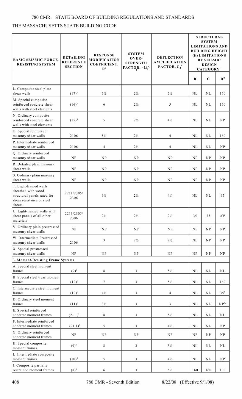
780 CMR: STATE BOARD OF BUILDING REGULATIONS AND STANDARDS
THE MASSACHUSETTS STATE BUILDING CODE
BASIC SEISMIC-FORCE-
RESISTING SYSTEM
DETAILING
REFERENCE
SECTION
RESPONSE
MODIFICATION
COEFFICIENT,
Ra
SYSTEM
OVER-
STRENGTH
oFACTOR, !S c,
g
DEFLECTION
AMPLIFICATION
dFACTOR, C b
STRUCTURAL
SYSTEM
LIMITATIONS AND
BUILDING HEIGHT
(ft) LIMITATIONS
BY SEISMIC
DESIGN
CATEGORY c
B C Dd
408 780 CMR - Seventh Edition 8/22/08 (Effective 9/1/08)
L. Composite steel plate
shear walls (17) 6½ 2½ 5½ NL NL 160k
M. Special composite
reinforced concrete shear
walls with steel elements
(16) 6 2½ 5 NL NL 160k
N. Ordinary composite
reinforced concrete shear
walls with steel elements
(15) 5 2½ 4½ NL NL NPk
O. Special reinforced
masonry shear walls 2106 5½ 2½ 4 NL NL 160
P. Intermediate reinforced
masonry shear walls 2106 4 2½ 4 NL NL NP
Q. Ordinary reinforced
masonry shear walls NP NP NP NP NP NP NP
R. Detailed plain masonry
shear walls NP NP NP NP NP NP NP
S. Ordinary plain masonry
shear walls NP NP NP NP NP NP NP
T. Light-framed walls
sheathed with wood
structural panels rated for
shear resistance or steel
sheets
2211/2305/
23066½ 2½ 4¼ NL NL 65
U. Light-framed walls with
shear panels of all other
materials
2211/2305/
23062½ 2½ 2½ 35 35 NP
V. Ordinary plain prestressed
masonry shear wallsNP NP NP NP NP NP NP
W. Intermediate Prestressed
masonry shear walls 21063 2½ 2½ NL NP NP
X. Special prestressed
masonry shear walls NP NP NP NP NP NP NP
3. Moment-Resisting Frame Systems
A. Special steel moment
frames (9) 8 3 5½ NL NL NLj
B. Special steel truss moment
frames (12) 7 3 5½ NL NL 160j
C. Intermediate steel moment
frames (10) 4½ 3 4 NL NL 35j h
D. Ordinary steel moment
frames (11) 3½ 3 3 NL NL NPj h,i
E. Special reinforced
concrete moment frames (21.1) 8 3 5½ NL NL NLl
F. Intermediate reinforced
concrete moment frames (21.1) 5 3 4½ NL NL NPl
G. Ordinary reinforced
concrete moment framesNP NP NP NP NP NP NP
H. Special composite
moment frames(9) 8 3 5½ NL NL NLk
I. Intermediate composite
moment frames (10) 5 3 4½ NL NL NPk
J. Composite partially
restrained moment frames (8) 6 3 5½ 160 160 100k
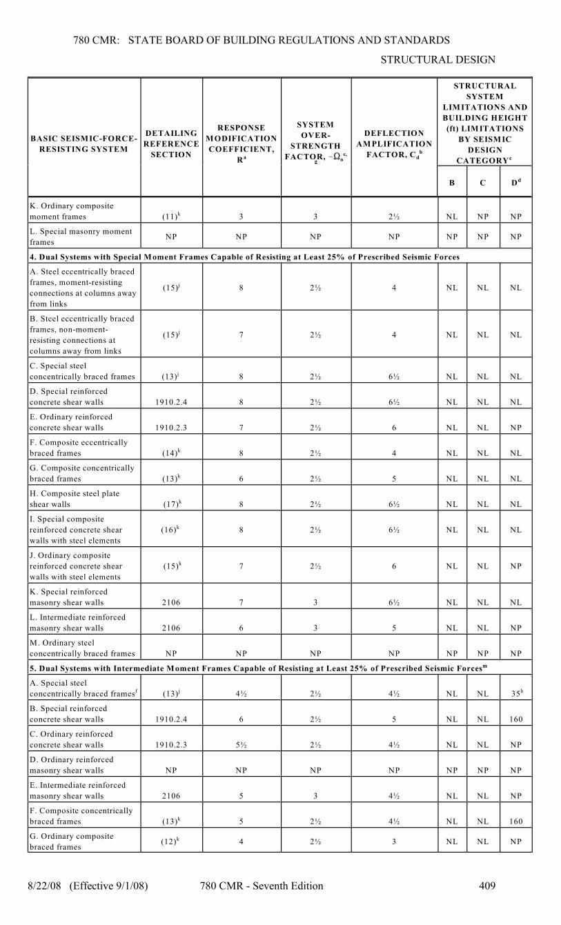
780 CMR: STATE BOARD OF BUILDING REGULATIONS AND STANDARDS
STRUCTURAL DESIGN
BASIC SEISMIC-FORCE-
RESISTING SYSTEM
DETAILING
REFERENCE
SECTION
RESPONSE
MODIFICATION
COEFFICIENT,
Ra
SYSTEM
OVER-
STRENGTH
oFACTOR, !S c,
g
DEFLECTION
AMPLIFICATION
dFACTOR, C b
STRUCTURAL
SYSTEM
LIMITATIONS AND
BUILDING HEIGHT
(ft) LIMITATIONS
BY SEISMIC
DESIGN
CATEGORY c
B C Dd
8/22/08 (Effective 9/1/08) 780 CMR - Seventh Edition 409
K. Ordinary composite
moment frames (11) 3 3 2½ NL NP NPk
L. Special masonry moment
framesNP NP NP NP NP NP NP
4. Dual Systems with Special Moment Frames Capable of Resisting at Least 25% of Prescribed Seismic Forces
A. Steel eccentrically braced
frames, moment-resisting
connections at columns away
from links
(15) 8 2½ 4 NL NL NLj
B. Steel eccentrically braced
frames, non-moment-
resisting connections at
columns away from links
(15) 7 2½ 4 NL NL NLj
C. Special steel
concentrically braced frames (13) 8 2½ 6½ NL NL NLj
D. Special reinforced
concrete shear walls 1910.2.4 8 2½ 6½ NL NL NL
E. Ordinary reinforced
concrete shear walls 1910.2.3 7 2½ 6 NL NL NP
F. Composite eccentrically
braced frames (14) 8 2½ 4 NL NL NLk
G. Composite concentrically
braced frames (13) 6 2½ 5 NL NL NLk
H. Composite steel plate
shear walls (17) 8 2½ 6½ NL NL NLk
I. Special composite
reinforced concrete shear
walls with steel elements
(16) 8 2½ 6½ NL NL NLk
J. Ordinary composite
reinforced concrete shear
walls with steel elements
(15) 7 2½ 6 NL NL NPk
K. Special reinforced
masonry shear walls 2106 7 3 6½ NL NL NL
L. Intermediate reinforced
masonry shear walls 2106 6 3 5 NL NL NP
M. Ordinary steel
concentrically braced frames NP NP NP NP NP NP NP
5. Dual Systems with Intermediate Moment Frames Capable of Resisting at Least 25% of Prescribed Seismic Forcesm
A. Special steel
concentrically braced frames (13) 4½ 2½ 4½ NL NL 35f j h
B. Special reinforced
concrete shear walls 1910.2.4 6 2½ 5 NL NL 160
C. Ordinary reinforced
concrete shear walls 1910.2.3 5½ 2½ 4½ NL NL NP
D. Ordinary reinforced
masonry shear walls NP NP NP NP NP NP NP
E. Intermediate reinforced
masonry shear walls 2106 5 3 4½ NL NL NP
F. Composite concentrically
braced frames (13) 5 2½ 4½ NL NL 160k
G. Ordinary composite
braced frames(12) 4 2½ 3 NL NL NPk
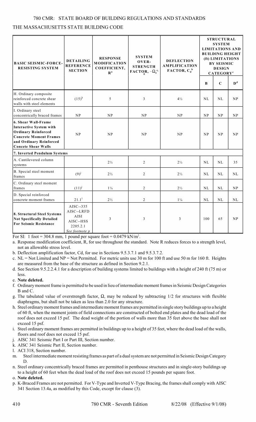
780 CMR: STATE BOARD OF BUILDING REGULATIONS AND STANDARDS
THE MASSACHUSETTS STATE BUILDING CODE
BASIC SEISMIC-FORCE-
RESISTING SYSTEM
DETAILING
REFERENCE
SECTION
RESPONSE
MODIFICATION
COEFFICIENT,
Ra
SYSTEM
OVER-
STRENGTH
oFACTOR, !S c,
g
DEFLECTION
AMPLIFICATION
dFACTOR, C b
STRUCTURAL
SYSTEM
LIMITATIONS AND
BUILDING HEIGHT
(ft) LIMITATIONS
BY SEISMIC
DESIGN
CATEGORY c
B C Dd
410 780 CMR - Seventh Edition 8/22/08 (Effective 9/1/08)
H. Ordinary composite
reinforced concrete shear
walls with steel elements
(15) 5 3 4½ NL NL NPk
I. Ordinary steel
concentrically braced frames NP NP NP NP NP NP NP
6. Shear Wall-Frame
Interactive System with
Ordinary Reinforced
Concrete Moment Frames
and Ordinary Reinforced
Concete Shear Walls
NP NP NP NP NP NP NP
7. Inverted Pendulum Systems
A. Cantilevered column
systems2½ 2 2½ NL NL 35
B. Special steel moment
frames(9) 2½ 2 2½ NL NL NLj
C. Ordinary steel moment
frames (11) 1¼ 2 2½ NL NL NPj
D. Special reinforced
concrete moment frames 21.1 2½ 2 1¼ NL NL NLl
8. Structural Steel Systems
Not Specifically Detailed
For Seismic Resistance
AISC--335
AISC--LRFD
AISI
AISC--HSS
2205.2.1
See footnote p
3 3 3 100 65 NP
For SI: 1 foot = 304.8 mm, 1 pound per square foot = 0.0479 kN/m .2
a. Response modification coefficient, R, for use throughout the standard. Note R reduces forces to a strength level,not an allowable stress level.
b. Deflection amplification factor, Cd, for use in Sections 9.5.3.7.1 and 9.5.3.7.2.c. NL = Not Limited and NP = Not Permitted. For metric units use 30 m for 100 ft and use 50 m for 160 ft. Heights
are measured from the base of the structure as defined in Section 9.2.1.d. See Section 9.5.2.2.4.1 for a description of building systems limited to buildings with a height of 240 ft (75 m) or
less.e. Note deleted.f. Ordinary moment frame is permitted to be used in lieu of intermediate moment frames in Seismic Design Categories
B and C.g. The tabulated value of overstrength factor, S, may be reduced by subtracting 1/2 for structures with flexible
diaphragms, but shall not be taken as less than 2.0 for any structure.h. Steel ordinary moment frames and intermediate moment frames are permitted in single story buildings up to a height
of 60 ft, when the moment joints of field connections are constructed of bolted end plates and the dead load of theroof does not exceed 15 psf. The dead weight of the portion of walls more than 35 feet above the base shall notexceed 15 psf.
i. Steel ordinary moment frames are permitted in buildings up to a height of 35 feet, where the dead load of the walls,floors and roof does not exceed 15 psf.
j. AISC 341 Seismic Part I or Part III, Section number.k. AISC 341 Seismic Part II, Section number.l. ACI 318, Section number.m. Steel intermediate moment resisting frames as part of a dual system are not permitted in Seismic Design Category
D.n. Steel ordinary concentrically braced frames are permitted in penthouse structures and in single-story buildings up
to a height of 60 feet when the dead load of the roof does not exceed 15 pounds per square foot.o. Note deleted.p. K-Braced Frames are not permitted. For V-Type and Inverted V-Type Bracing, the frames shall comply with AISC
341 Section 13.4a, as modified by this Code, except for clause (3).
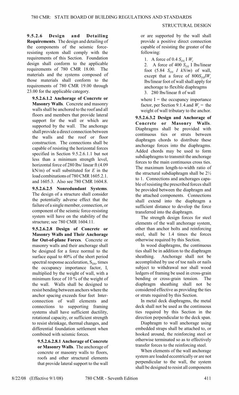
780 CMR: STATE BOARD OF BUILDING REGULATIONS AND STANDARDS
STRUCTURAL DESIGN
8/22/08 (Effective 9/1/08) 780 CMR - Seventh Edition 411
9.5.2.6 Design and DetailingRequirements. The design and detailing ofthe components of the seismic force-resisting system shall comply with therequirements of this Section. Foundationdesign shall conform to the applicablerequirements of 780 CMR 18.00. Thematerials and the systems composed ofthose materials shall conform to therequirements of 780 CMR 19.00 through23.00 for the applicable category.
9.5.2.6.1.2 Anchorage of Concrete orMasonry Walls. Concrete and masonrywalls shall be anchored to the roof and allfloors and members that provide lateralsupport for the wall or which aresupported by the wall. The anchorageshall provide a direct connection betweenthe walls and the roof or floorconstruction. The connections shall becapable of resisting the horizontal forcesspecified in Section 9.5.2.6.1.1 but notless than a minimum strength level,horizontal force of 280 lbs/ linear ft (4.09kN/m) of wall substituted for E in theload combinations of 780 CMR 1605.2.1.and 1605.3. Also see 780 CMR 1604.8.
9.5.2.6.2.5 Nonredundant Systems.The design of a structure shall considerthe potentially adverse effect that thefailure of a single member, connection, orcomponent of the seismic force-resistingsystem will have on the stability of thestructure; see 780 CMR 1604.11.
9.5.2.6.2.8 Design of Concrete orMasonry Walls and Their Anchoragefor Out-of-plane Forces. Concrete ormasonry walls and their anchorage shallbe designed for a force normal to thesurface equal to 40% of the short period
DSspectral response acceleration, S , timesthe occupancy importance factor, I,multiplied by the weight of wall, with aminimum force of 10 % of the weight ofthe wall. Walls shall be designed toresist bending between anchors where theanchor spacing exceeds four feet Inter-connection of wall elements andconnections to supporting framingsystems shall have sufficient ductility,rotational capacity, or sufficient strengthto resist shrinkage, thermal changes, anddifferential foundation settlement whencombined with seismic forces.
9.5.2.6.2.8.1 Anchorage of Concreteor Masonry Walls. The anchorage ofconcrete or masonry walls to floors,roofs and other structural elementsthat provide lateral support to the wall
or are supported by the wall shallprovide a positive direct connectioncapable of resisting the greater of thefollowing:
DS c1. A force of 0.4 S I W
DS2. A force of 400 S I lbs/linear
DSfoot (5.84 S I kN/m) of wall,
DS cexcept that a force of 800S IWlbs/linear foot of wall shall apply foranchorage to flexible diaphragms3. 280 lbs/linear ft of wall
where I = the occupancy importance
cfactor, per Section 9.1.4.and W = theweight of wall tributary to the anchor.
9.5.2.6.3.2 Design and Anchorage ofConcrete or Masonry Walls.Diaphragms shall be provided withcontinuous ties or struts betweendiaphragm chords to distribute theseanchorage forces into the diaphragms.Added chords may be used to formsubdiaphragms to transmit the anchorageforces to the main continuous cross ties.The maximum length-to-width ratio ofthe structural subdiaphragm shall be 2½to 1. Connections and anchorages capa-ble of resisting the prescribed forces shallbe provided between the diaphragm andthe attached components. Connectionsshall extend into the diaphragm asufficient distance to develop the forcetransferred into the diaphragm.
The strength design forces for steelelements of the wall anchorage system,other than anchor bolts and reinforcingsteel, shall be 1.4 times the forcesotherwise required by this Section.
In wood diaphragms, the continuousties shall be in addition to the diaphragmsheathing. Anchorage shall not beaccomplished by use of toe nails or nailssubject to withdrawal nor shall woodledgers of framing be used in cross-grainbending or cross-grain tension. Thediaphragm sheathing shall not beconsidered effective as providing the tiesor struts required by this Section.
In metal deck diaphragms, the metaldeck shall not be used as the continuousties required by this Section in thedirection perpendicular to the deck span.
Diaphragm to wall anchorage usingembedded straps shall be attached to, orhooked around, the reinforcing steel orotherwise terminated so as to effectivelytransfer forces to the reinforcing steel.
When elements of the wall anchoragesystem are loaded eccentrically or are notperpendicular to the wall, the systemshall be designed to resist all components
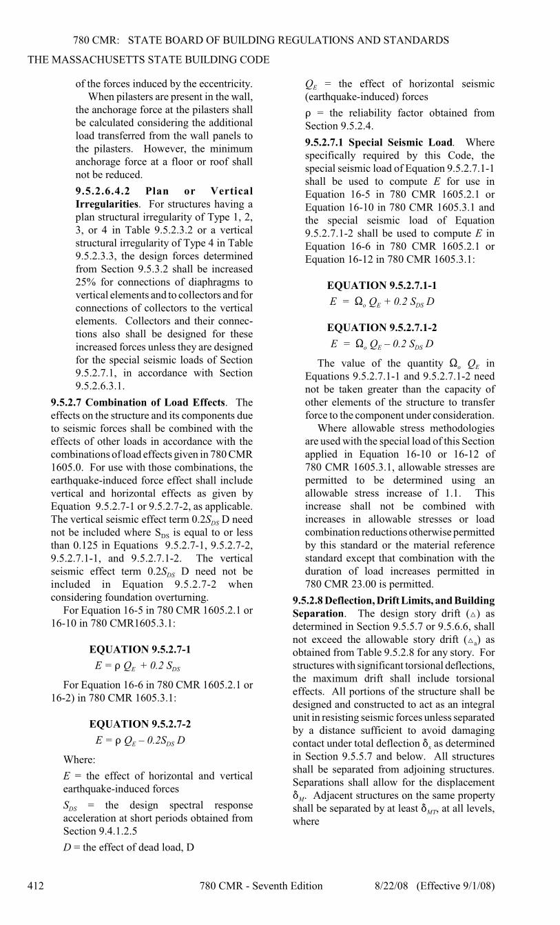
780 CMR: STATE BOARD OF BUILDING REGULATIONS AND STANDARDS
THE MASSACHUSETTS STATE BUILDING CODE
412 780 CMR - Seventh Edition 8/22/08 (Effective 9/1/08)
of the forces induced by the eccentricity.When pilasters are present in the wall,
the anchorage force at the pilasters shallbe calculated considering the additionalload transferred from the wall panels tothe pilasters. However, the minimumanchorage force at a floor or roof shallnot be reduced.
9.5.2.6.4.2 Plan or VerticalIrregularities. For structures having aplan structural irregularity of Type 1, 2,3, or 4 in Table 9.5.2.3.2 or a verticalstructural irregularity of Type 4 in Table9.5.2.3.3, the design forces determinedfrom Section 9.5.3.2 shall be increased25% for connections of diaphragms tovertical elements and to collectors and forconnections of collectors to the verticalelements. Collectors and their connec-tions also shall be designed for theseincreased forces unless they are designedfor the special seismic loads of Section9.5.2.7.1, in accordance with Section9.5.2.6.3.1.
9.5.2.7 Combination of Load Effects. Theeffects on the structure and its components dueto seismic forces shall be combined with theeffects of other loads in accordance with thecombinations of load effects given in 780 CMR1605.0. For use with those combinations, theearthquake-induced force effect shall includevertical and horizontal effects as given byEquation 9.5.2.7-1 or 9.5.2.7-2, as applicable.
DSThe vertical seismic effect term 0.2S D need
DSnot be included where S is equal to or lessthan 0.125 in Equations 9.5.2.7-1, 9.5.2.7-2,9.5.2.7.1-1, and 9.5.2.7.1-2. The vertical
DSseismic effect term 0.2S D need not beincluded in Equation 9.5.2.7-2 whenconsidering foundation overturning.
For Equation 16-5 in 780 CMR 1605.2.1 or16-10 in 780 CMR1605.3.1:
EQUATION 9.5.2.7-1
E DSE = D Q + 0.2 S
For Equation 16-6 in 780 CMR 1605.2.1 or16-2) in 780 CMR 1605.3.1:
EQUATION 9.5.2.7-2
E DSE = D Q – 0.2S D
Where:
E = the effect of horizontal and verticalearthquake-induced forces
DSS = the design spectral responseacceleration at short periods obtained fromSection 9.4.1.2.5
D = the effect of dead load, D
EQ = the effect of horizontal seismic(earthquake-induced) forces
D = the reliability factor obtained fromSection 9.5.2.4.
9.5.2.7.1 Special Seismic Load. Wherespecifically required by this Code, thespecial seismic load of Equation 9.5.2.7.1-1shall be used to compute E for use inEquation 16-5 in 780 CMR 1605.2.1 orEquation 16-10 in 780 CMR 1605.3.1 andthe special seismic load of Equation9.5.2.7.1-2 shall be used to compute E inEquation 16-6 in 780 CMR 1605.2.1 orEquation 16-12 in 780 CMR 1605.3.1:
EQUATION 9.5.2.7.1-1
o E DSE = S Q + 0.2 S D
EQUATION 9.5.2.7.1-2
o E DSE = S Q – 0.2 S D
o EThe value of the quantity S Q inEquations 9.5.2.7.1-1 and 9.5.2.7.1-2 neednot be taken greater than the capacity ofother elements of the structure to transferforce to the component under consideration.
Where allowable stress methodologiesare used with the special load of this Sectionapplied in Equation 16-10 or 16-12 of780 CMR 1605.3.1, allowable stresses arepermitted to be determined using anallowable stress increase of 1.1. Thisincrease shall not be combined withincreases in allowable stresses or loadcombination reductions otherwise permittedby this standard or the material referencestandard except that combination with theduration of load increases permitted in780 CMR 23.00 is permitted.
9.5.2.8 Deflection, Drift Limits, and BuildingSeparation. The design story drift (Î) asdetermined in Section 9.5.5.7 or 9.5.6.6, shall
anot exceed the allowable story drift (Î ) asobtained from Table 9.5.2.8 for any story. Forstructures with significant torsional deflections,the maximum drift shall include torsionaleffects. All portions of the structure shall bedesigned and constructed to act as an integralunit in resisting seismic forces unless separatedby a distance sufficient to avoid damaging
xcontact under total deflection * as determinedin Section 9.5.5.7 and below. All structuresshall be separated from adjoining structures.Separations shall allow for the displacement
M* . Adjacent structures on the same property
MTshall be separated by at least * , at all levels,where
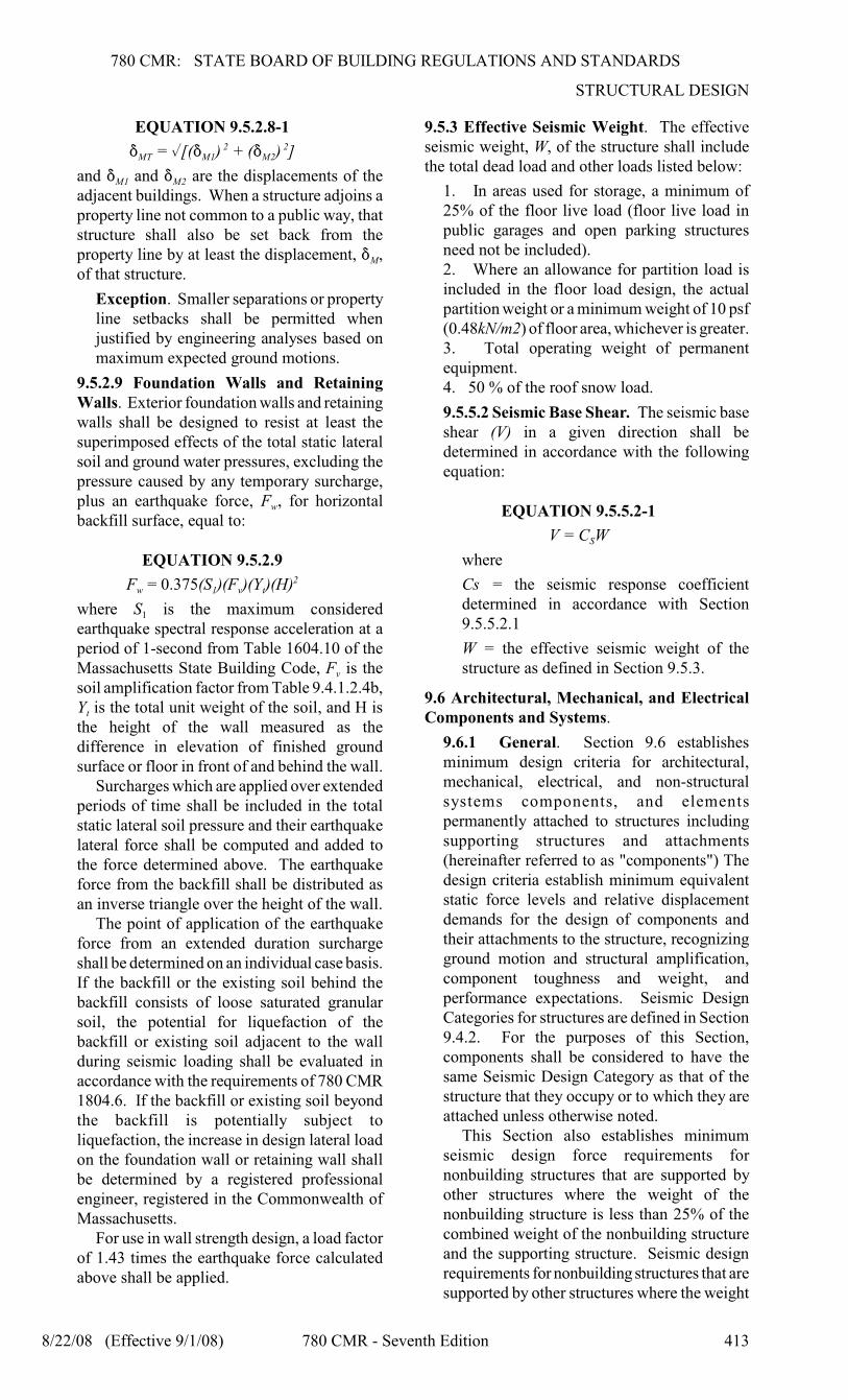
780 CMR: STATE BOARD OF BUILDING REGULATIONS AND STANDARDS
STRUCTURAL DESIGN
8/22/08 (Effective 9/1/08) 780 CMR - Seventh Edition 413
EQUATION 9.5.2.8-1
MT M1 M2* = %[(* ) + (* ) ] 2 2
M1 M2and * and * are the displacements of theadjacent buildings. When a structure adjoins aproperty line not common to a public way, thatstructure shall also be set back from the
Mproperty line by at least the displacement, * ,of that structure.
Exception. Smaller separations or propertyline setbacks shall be permitted whenjustified by engineering analyses based onmaximum expected ground motions.
9.5.2.9 Foundation Walls and RetainingWalls. Exterior foundation walls and retainingwalls shall be designed to resist at least thesuperimposed effects of the total static lateralsoil and ground water pressures, excluding thepressure caused by any temporary surcharge,
wplus an earthquake force, F , for horizontalbackfill surface, equal to:
EQUATION 9.5.2.9
w 1 v tF = 0.375(S )(F )(Y )(H)2
1where S is the maximum consideredearthquake spectral response acceleration at aperiod of 1-second from Table 1604.10 of the
vMassachusetts State Building Code, F is thesoil amplification factor from Table 9.4.1.2.4b,
tY is the total unit weight of the soil, and H isthe height of the wall measured as thedifference in elevation of finished groundsurface or floor in front of and behind the wall.
Surcharges which are applied over extendedperiods of time shall be included in the totalstatic lateral soil pressure and their earthquakelateral force shall be computed and added tothe force determined above. The earthquakeforce from the backfill shall be distributed asan inverse triangle over the height of the wall.
The point of application of the earthquakeforce from an extended duration surchargeshall be determined on an individual case basis.If the backfill or the existing soil behind thebackfill consists of loose saturated granularsoil, the potential for liquefaction of thebackfill or existing soil adjacent to the wallduring seismic loading shall be evaluated inaccordance with the requirements of 780 CMR1804.6. If the backfill or existing soil beyondthe backfill is potentially subject toliquefaction, the increase in design lateral loadon the foundation wall or retaining wall shallbe determined by a registered professionalengineer, registered in the Commonwealth ofMassachusetts.
For use in wall strength design, a load factorof 1.43 times the earthquake force calculatedabove shall be applied.
9.5.3 Effective Seismic Weight. The effectiveseismic weight, W, of the structure shall includethe total dead load and other loads listed below:
1. In areas used for storage, a minimum of25% of the floor live load (floor live load inpublic garages and open parking structuresneed not be included).2. Where an allowance for partition load isincluded in the floor load design, the actualpartition weight or a minimum weight of 10 psf(0.48kN/m2) of floor area, whichever is greater.3. Total operating weight of permanentequipment.4. 50 % of the roof snow load.
9.5.5.2 Seismic Base Shear. The seismic baseshear (V) in a given direction shall bedetermined in accordance with the followingequation:
EQUATION 9.5.5.2-1
SV = C W
where
Cs = the seismic response coefficientdetermined in accordance with Section9.5.5.2.1
W = the effective seismic weight of thestructure as defined in Section 9.5.3.
9.6 Architectural, Mechanical, and ElectricalComponents and Systems.
9.6.1 General. Section 9.6 establishesminimum design criteria for architectural,mechanical, electrical, and non-structuralsystems components, and elementspermanently attached to structures includingsupporting structures and attachments(hereinafter referred to as "components") Thedesign criteria establish minimum equivalentstatic force levels and relative displacementdemands for the design of components andtheir attachments to the structure, recognizingground motion and structural amplification,component toughness and weight, andperformance expectations. Seismic DesignCategories for structures are defined in Section9.4.2. For the purposes of this Section,components shall be considered to have thesame Seismic Design Category as that of thestructure that they occupy or to which they areattached unless otherwise noted.
This Section also establishes minimumseismic design force requirements fornonbuilding structures that are supported byother structures where the weight of thenonbuilding structure is less than 25% of thecombined weight of the nonbuilding structureand the supporting structure. Seismic designrequirements for nonbuilding structures that aresupported by other structures where the weight
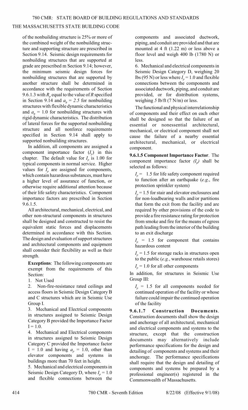
780 CMR: STATE BOARD OF BUILDING REGULATIONS AND STANDARDS
THE MASSACHUSETTS STATE BUILDING CODE
414 780 CMR - Seventh Edition 8/22/08 (Effective 9/1/08)
of the nonbuilding structure is 25% or more ofthe combined weight of the nonbuilding struc-ture and supporting structure are prescribed inSection 9.14. Seismic design requirements fornonbuilding structures that are supported atgrade are prescribed m Section 9.14; however,the minimum seismic design forces fornonbuilding structures that are supported byanother structure shall be determined inaccordance with the requirements of Section
p9.6.1.3 with R equal to the value of R specified
pin Section 9.14 and a = 2.5 for nonbuildingstructures with flexible dynamic characteristics
pand a = 1.0 for nonbuilding structures withrigid dynamic characteristics. The distributionof lateral forces for the supported nonbuildingstructure and all nonforce requirementsspecified in Section 9.14 shall apply tosupported nonbuilding structures.
In addition, all components are assigned a
pcomponent importance factor (I ) in this
pchapter. The default value for I is 1.00 fortypical components in normal service. Higher
pvalues for I are assigned for components,which contain hazardous substances, must havea higher level of assurance of function, orotherwise require additional attention becauseof their life safety characteristics. Componentimportance factors are prescribed in Section9.6.1.5.
All architectural, mechanical, electrical, andother non-structural components in structuresshall be designed and constructed to resist theequivalent static forces and displacementsdetermined in accordance with this Section.The design and evaluation of support structuresand architectural components and equipmentshall consider their flexibility as well as theirstrength.
Exceptions: The following components areexempt from the requirements of thisSection:1. Not Used2. Non-fire-resistance rated ceilings andaccess floors in Seismic Design Category Band C structures which are in Seismic UseGroup I.3. Mechanical and Electrical componentsin structures assigned to Seismic DesignCategory B provided the Importance FactorI = 1.0.4. Mechanical and Electrical componentsin structures assigned to Seismic DesignCategory C provided the Importance factor
pI = 1.0 and having a = 1.0, other thanelevator components and systems inbuildings more than 70 feet in height.5. Mechanical and electrical components in
pSeismic Design Category D, where I = 1.0and flexible connections between the
components and associated ductwork,piping, and conduit are provided and that aremounted at 4 ft (1.22 m) or less above afloor level and weigh 400 lb (1780 N) orless.6. Mechanical and electrical components inSeismic Design Category D, weighing 20
plbs (95 N) or less where I = 1.0 and flexibleconnections between the components andassociated ductwork, piping, and conduit areprovided, or for distribution systems,weighing 5 lb/ft (7 N/m) or less.
The functional and physical interrelationshipof components and their effect on each othershall be designed so that the failure of anessential or nonessential architectural,mechanical, or electrical component shall notcause the failure of a nearby essentialarchitectural, mechanical, or electricalcomponent.
9.6.1.5 Component Importance Factor. The
pcomponent importance factor (I ) shall beselected as follows:
pI = 1.5 for life safety component requiredto function after an earthquake (e.g., fireprotection sprinkler system)
pI = 1.5 for stair and elevator enclosures andfor non-loadbearing walls and/or partitionsthat form the exit from the facility and arerequired by other provisions of the code toprovide a fire resistance rating for protectionfrom smoke and fire for the means of egresspath leading from the interior of the buildingto an exit discharge
pI = 1.5 for component that containshazardous content
pI = 1.5 for storage racks in structures opento the public (e.g., warehouse retails stores)
pI = 1.0 for all other components
In addition, for structures in Seismic UseGroup III:
pI = 1.5 for all components needed forcontinued operation of the facility or whosefailure could impair the continued operationof the facility
9.6.1.7 Construction Documents.Construction documents shall show the designand anchorage of all architectural, mechanicaland electrical components and systems to thestructure, except that the constructiondocuments may alternatively includeperformance specifications for the design anddetailing of components and systems and theiranchorage. The performance specificationsshall require that the design and detailing ofcomponents and systems be prepared by aprofessional engineer(s) registered in theCommonwealth of Massachusetts.
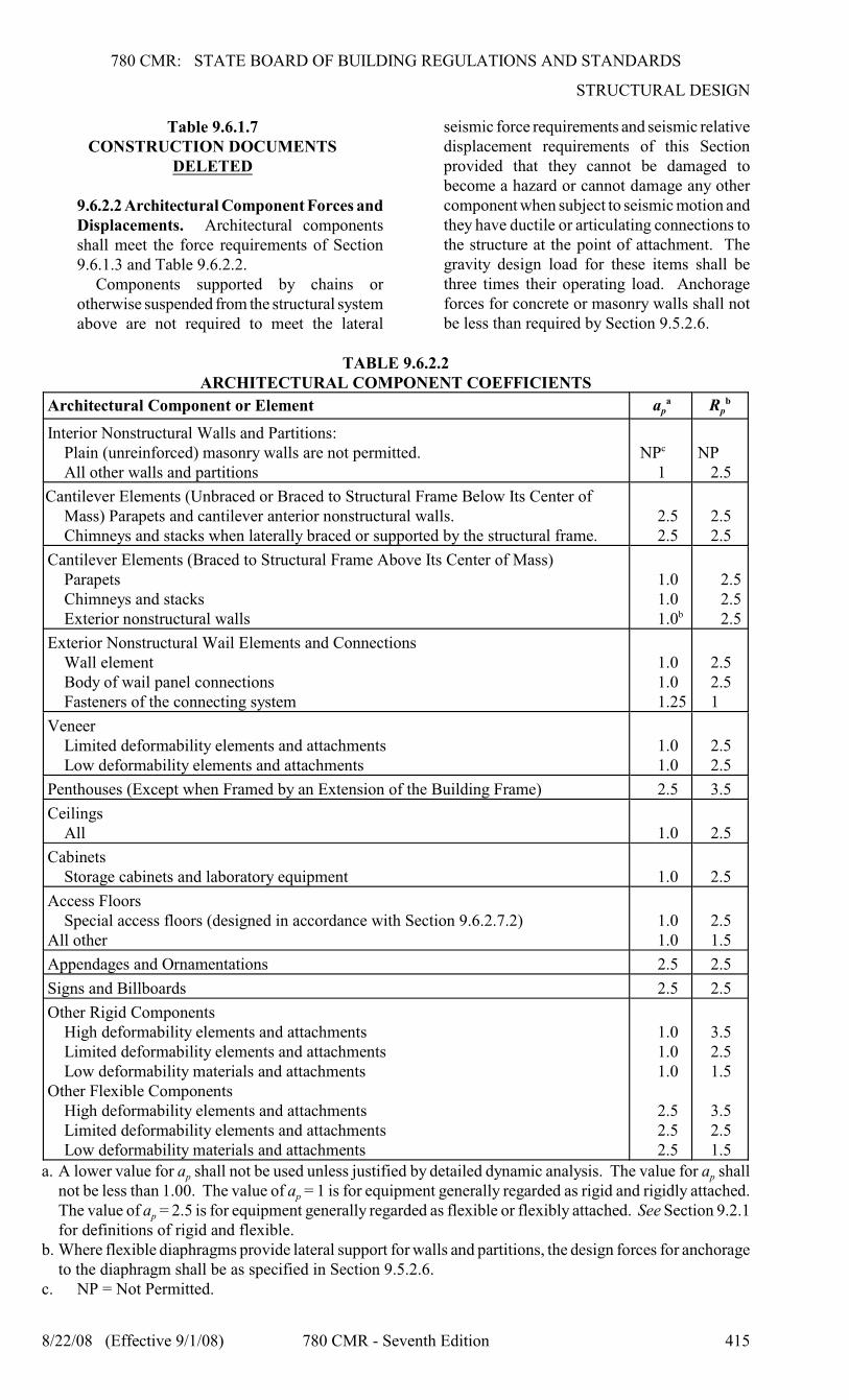
780 CMR: STATE BOARD OF BUILDING REGULATIONS AND STANDARDS
STRUCTURAL DESIGN
8/22/08 (Effective 9/1/08) 780 CMR - Seventh Edition 415
Table 9.6.1.7CONSTRUCTION DOCUMENTS
DELETED
9.6.2.2 Architectural Component Forces andDisplacements. Architectural componentsshall meet the force requirements of Section9.6.1.3 and Table 9.6.2.2.
Components supported by chains orotherwise suspended from the structural systemabove are not required to meet the lateral
seismic force requirements and seismic relativedisplacement requirements of this Sectionprovided that they cannot be damaged tobecome a hazard or cannot damage any othercomponent when subject to seismic motion andthey have ductile or articulating connections tothe structure at the point of attachment. Thegravity design load for these items shall bethree times their operating load. Anchorageforces for concrete or masonry walls shall notbe less than required by Section 9.5.2.6.
TABLE 9.6.2.2ARCHITECTURAL COMPONENT COEFFICIENTS
Architectural Component or Element p pa Ra b
Interior Nonstructural Walls and Partitions:Plain (unreinforced) masonry walls are not permitted.All other walls and partitions
NPc
1NP
2.5
Cantilever Elements (Unbraced or Braced to Structural Frame Below Its Center ofMass) Parapets and cantilever anterior nonstructural walls.Chimneys and stacks when laterally braced or supported by the structural frame.
2.52.5
2.52.5
Cantilever Elements (Braced to Structural Frame Above Its Center of Mass)ParapetsChimneys and stacksExterior nonstructural walls
1.01.01.0b
2.52.52.5
Exterior Nonstructural Wail Elements and ConnectionsWall elementBody of wail panel connectionsFasteners of the connecting system
1.01.01.25
2.52.51
VeneerLimited deformability elements and attachmentsLow deformability elements and attachments
1.01.0
2.52.5
Penthouses (Except when Framed by an Extension of the Building Frame) 2.5 3.5
CeilingsAll 1.0 2.5
CabinetsStorage cabinets and laboratory equipment 1.0 2.5
Access FloorsSpecial access floors (designed in accordance with Section 9.6.2.7.2)
All other1.01.0
2.51.5
Appendages and Ornamentations 2.5 2.5
Signs and Billboards 2.5 2.5
Other Rigid ComponentsHigh deformability elements and attachmentsLimited deformability elements and attachmentsLow deformability materials and attachments
Other Flexible ComponentsHigh deformability elements and attachmentsLimited deformability elements and attachmentsLow deformability materials and attachments
1.01.01.0
2.52.52.5
3.52.51.5
3.52.51.5
p pa. A lower value for a shall not be used unless justified by detailed dynamic analysis. The value for a shall
pnot be less than 1.00. The value of a = 1 is for equipment generally regarded as rigid and rigidly attached.
pThe value of a = 2.5 is for equipment generally regarded as flexible or flexibly attached. See Section 9.2.1for definitions of rigid and flexible.
b. Where flexible diaphragms provide lateral support for walls and partitions, the design forces for anchorageto the diaphragm shall be as specified in Section 9.5.2.6.
c. NP = Not Permitted.
780 CMR: STATE BOARD OF BUILDING REGULATIONS AND STANDARDS
THE MASSACHUSETTS STATE BUILDING CODE
416 780 CMR - Seventh Edition 8/22/08 (Effective 9/1/08)
9.6.2.6.2.1 Seismic Design Categories Band C. Suspended ceilings in SeismicDesign Categories B and C shall bedesigned and installed in accordance withthe CISCA recommendations for seismicZones 0-2, (Ref. 9.6-16), except thatseismic forces shall be determined inaccordance with Sections 9.6.1.3 and9.6.2.6.1. Note that design of non-fire-resistance rated ceilings in SeismicDesign Categories B and C which are inSeismic Use Group I need not meet theserequirements.
Sprinkler heads and other penetrationsin Seismic Design Category C shall havea minimum of 1/4 in. (6 mm) clearanceon all sides.
9.13.6.2.3 Fire Resistance. Fire resistanceratings of the isolation system shall complywith 780 CMR 714.7.
9.14.6.6.1 General. Piers and wharves arestructures located in waterfront areas thatproject into a body of water or parallel theshoreline. A pier or wharf supporting abuilding or buildings shall be designedconsidering soil-structure interaction and thedynamic properties of the combinedbuilding/pier or building/wharf structure forearthquake loads specified in this Code.
780 CMR 1616.0 THROUGH 1623.0
RESERVED
780 CMR 1624.0 IN-SITU LOAD TESTS
1624.1 General. Whenever there is a reasonabledoubt as to the stability or load-bearing capacity ofa completed building, structure or portion thereof forthe expected loads, an engineering assessment shallbe required. The engineering assessment shallinvolve either a structural analysis or an in-situ loadtest, or both. The structural analysis shall be basedon actual material properties and other as-builtconditions that affect stability or load-bearingcapacity, and shall be conducted in accordance withthe applicable design standard. If the structuralassessment determines that the load-bearing capacityis less than that required by the code, load tests shallbe conducted in accordance with 780 CMR 1624.2.If the building, structure or portion thereof is foundto have inadequate stability or load-bearing capacityfor the expected loads, modifications to ensurestructural adequacy or the removal of the inadequateconstruction shall be required.
1624.2 Test Standards. Structural components andassemblies shall be tested in accordance with theappropriate material standards listed in 780 CMR35.00. In the absence of a standard that contains anapplicable load test procedure, the test procedureshall be developed by a registered design
professional and approved. The test procedure shallsimulate loads and conditions of application that thecompleted structure or portion thereof will besubjected to in normal use.
1624.3 In-situ Load Tests. In-situ load tests shallbe conducted in accordance with 780 CMR 1624.3.1or 1624.3.2 and shall be supervised by a registereddesign professional. The test shall simulate theapplicable loading conditions specified in 780 CMR16.00 as necessary to address the concerns regardingstructural stability of the building, structure orportion thereof.
1624.3.1 Load Test Procedure Specified.Where a standard listed in 780 CMR 35.00contains an applicable load test procedure andacceptance criteria, the test procedure andacceptance criteria in the standard shall apply. Inthe absence of specific load factors or acceptancecriteria, the load factors and acceptance criteria in780 CMR 1624.3.2 shall apply.
1624.3.2 Load Test Procedure Not Specified. Inthe absence of applicable load test procedurescontained within a standard referenced by780 CMR or acceptance criteria for a specificmaterial or method of construction, such existingstructure shall be subjected to a test proceduredeveloped by a registered design professional thatsimulates applicable loading and deformation con-ditions. For components that are not a part of theseismic load-resisting system, the test load shallbe equal to two times the unfactored design loads.The test load shall be left in place for a period of24 hours. The structure shall be considered tohave successfully met the test requirements wherethe following criteria are satisfied:
1. Under the design load, the deflection shallnot exceed the limitations specified in780 CMR 1604.3.2. Within 24 hours after removal of the testload, the structure shall have recovered not lessthan 75% of the maximum deflection.3. During and immediately after the test, thestructure shall not show evidence of failure.
780 CMR 1625.0 ALTERNATIVE TEST
PROCEDURE
1625.1 General. For materials and assemblies thatare not specifically provided for in 780 CMR, thedesign strengths and permissible stresses shall beestablished by tests or a combination of tests andstructural analysis.
1625.2 Tests by Approved Agencies. The buildingofficial shall accept duly authenticated reports fromapproved agencies in respect to the quality andmanner of use of new materials or assemblies asprovided for in 780 CMR 109.4.
1625.3 Cost of Tests. The cost of all tests and otherinvestigations required under the provisions of
780 CMR: STATE BOARD OF BUILDING REGULATIONS AND STANDARDS
STRUCTURAL DESIGN
8/22/08 (Effective 9/1/08) 780 CMR - Seventh Edition 417
780 CMR shall be borne by the permit applicant.
780 CMR 1626.0 TEST SAFE LOAD
1626.1 Where Required. Where proposedconstruction is not capable of being designed byapproved engineering analysis, or where proposedconstruction design method does not comply withthe applicable material design standard, the systemof construction or the structural unit and theconnections shall be subjected to the tests prescribedin 780 CMR 1627.0. The building official shallaccept certified reports of such tests conducted by anapproved testing agency, provided that such testsmeet the requirements of 780 CMR and approvedprocedures.
780 CMR 1627.0 PRECONSTRUCTION
LOAD TESTS
1627.1 General. In evaluating the physicalproperties of materials and methods of constructionthat are not capable of being designed by approvedengineering analysis or that do not comply withapplicable material design standards listed in780 CMR 35.00, the structural adequacy shall bepredetermined based on the load test criteriaestablished in 780 CMR 1627.0.
1627.2 Load Test Procedures Specified. Wherespecific load test procedures, load factors andacceptance criteria are included in the applicabledesign standards listed in 780 CMR 35.00, such testprocedures, load factors and acceptance criteria shallapply. In the absence of specific test procedures,load factors or acceptance criteria, the correspondingprovisions in 780 CMR 1627.3 shall apply.
1627.3 Load Test Procedures Not Specified.Where load test procedures are not specified in theapplicable design standards listed in 780 CMR35.00, the load-bearing and deformation capacity ofstructural components and assemblies shall bedetermined on the basis of a test proceduredeveloped by a registered design professional thatsimulates applicable loading and deformationconditions. For components and assemblies that arenot a part of the seismic load-resisting system, thetest shall be as specified in 780 CMR 1627.3.1.Load tests shall simulate the applicable loadingconditions specified in 780 CMR 16.00.
1627.3.1 Test Procedure. The test assemblyshall be subjected to an increasing superimposedload equal to not less than two times thesuperimposed design load. The test load shall beleft in place for a period of 24 hours. The testedassembly shall be considered to have successfullymet the test requirements if the assembly recoversnot less than 75% of the maximum deflectionwithin 24 hours after the removal of the test load.The test assembly shall then be reloaded andsubjected to an increasing superimposed load until
either structural failure occurs or thesuperimposed load is equal to two and one-halftimes the load at which the deflection limitationsspecified in 780 CMR 1627.3.2 were reached, orthe load is equal to two and one-half times thesuperimposed design load. In the case ofstructural components and assemblies for whichdeflection limitations are not specified in780 CMR 1627.3.2, the test specimen shall besubjected to an increasing superimposed load untilstructural failure occurs or the load is equal to twoand one-half times the desired superimposeddesign load. The allowable superimposed designload shall be taken as the lesser of:
1. The load at the deflection limitation givenin 780 CMR 1627.3.2.2. The failure load divided by 2.5.3. The maximum load applied divided by 2.5.
1627.3.2 Deflection. The deflection of structuralmembers under the design load shall not exceedthe limitations in 780 CMR 1604.3.
1627.4 Wall and Partition Assemblies. Load-bearing wall and partition assemblies shall sustainthe test load both with and without window framing.The test load shall include all design loadcomponents. Wall and partition assemblies shall betested both with and without door and windowframing.
1627.5 Exterior Window and Door Assemblies.The design pressure rating of exterior windows anddoors in buildings shall be determined in accordancewith 780 CMR 1627.5.1 or 1627.5.2.
Exception. Structural wind load design pressuresfor window units smaller than the size tested inaccordance with 780 CMR 1627.5.1 or 1627.5.2shall be permitted to be higher than the designvalue of the tested unit provided such higherpressures are determined by accepted engineeringanalysis. All components of the small unit shallbe the same as the tested unit. Where suchcalculated design pressures are used, they shall bevalidated by an additional test of the window unithaving the highest allowable design pressure.
1627.5.1 Aluminum, Vinyl and Wood ExteriorWindows and Glass Doors. Aluminum, vinyl andwood exterior windows and glass doors shall belabeled as conforming to AAMA/NWWDA101/I.S.2 or 101/I.S.2/NAFS. The label shall statethe name of the manufacturer, the approved labelingagency and the product designation as specified inAAMA/NWWDA 101/I.S.2 or 101/I.S.2/NAFS.Products tested and labeled as conforming toAAMA/NWWDA 101/I.S.2 or 101/I.S.2/NAFS shallnot be subject to the requirements of 780 CMR2403.2 and 2403.3.
1627.5.2 Exterior Windows and DoorAssemblies Not Provided for in 780 CMR1627.5.1. Exterior window and door assembliesshall be tested in accordance with ASTM E 330.
780 CMR: STATE BOARD OF BUILDING REGULATIONS AND STANDARDS
THE MASSACHUSETTS STATE BUILDING CODE
418 780 CMR - Seventh Edition 8/22/08 (Effective 9/1/08)
Exterior window and door assemblies containingglass shall comply with 780 CMR 2403. The designpressure for testing shall be calculated in accordancewith 780 CMR 16.00. Each assembly shall be testedfor ten seconds at a load equal to 1.5 times thedesign pressure.
1627.6 Test Specimens. Test specimens andconstruction shall be representative of the materials,
workmanship and details normally used in practice.The properties of the materials used to construct thetest assembly shall be determined on the basis oftests on samples taken from the load assembly or onrepresentative samples of the materials used toconstruct the load test assembly. Required tests shallbe conducted or witnessed by an approved agency.