Embed Size (px)
Citation preview
785 HIM
Softener, Iron & Manganese
Reduction System
Ow
ners
Man
ual
REVISION # 0 REVISION DATE May 4,2015 54613
1. Read all instructions carefully before operation. 2. Avoid pinched o-rings during installation by applying (provided with install kit) NSF
certified lubricant to all seals. 3. This system is not intended for treating water that is microbiologically unsafe or of
unknown quality without adequate disinfection before or after the system.
Canadian Head Office
655 Park St. Regina, SK S4N 5N1
U.S. Head Office 8437 10th Avenue North Golden Valley, MN 55427
Safety Guide
Check and comply with your provincial / state and local codes. You must follow these guidelines.
Use care when handling the water soften-ing system. Do not turn upside down, drop, drag or set on sharp protrusions.
The water softening system works on 12 volt-60 Hz electrical power only. Be sure to use only the included transformer.
Transformer must be plugged into an in-door 120 volt, grounded outlet only.
Use clean water softening salts only, at least 99.5% pure. NUGGET, PELLET or
coarse SOLAR salts are recommended. Do not use rock, block, granulated or ice cream making salts. They contain dirt and sediments, or mush and cake, and will cre-ate maintenance problems.
Keep the salt lid in place on the softener unless servicing the unit or refilling with salt.
WARNING: This system is not in-tended for treating water that is microbio-logically unsafe or of unknown quality without adequate disinfection before or after the system.
For your safety, the information in this manual must be followed to minimize the risk of electric shock, property damage or personal injury.
Be sure to check the entire softener for any shipping damage or parts loss. Also note dam-age to the shipping cartons. Contact the transportation company for all damage and loss claims. The manufacturer is not responsible for damages in transit. Small parts, needed to install the softener, are in a parts bag. To avoid loss of the small parts, keep them in the parts bag until you are ready to use them.
Unpacking / Inspection
PAGE Unpacking / Inspection 2 Safety Guide 2 Proper Installation 3 Specification 4 Before Starting Installation 4 Installation Instructions 6 System Start Up 8 Programming Instructions 9 About The System 10 Maintenance 12 Sanitizing Procedure 15 Main Repair Parts 17 Trouble Shooting 23 Warranty 24
Table of Contents 2
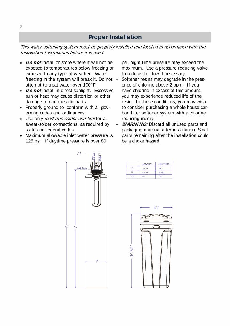
Proper Installation This water softening system must be properly installed and located in accordance with the Installation Instructions before it is used.
Do not install or store where it will not be exposed to temperatures below freezing or exposed to any type of weather. Water freezing in the system will break it. Do not attempt to treat water over 100°F.
Do not install in direct sunlight. Excessive sun or heat may cause distortion or other damage to non-metallic parts.
Properly ground to conform with all gov-erning codes and ordinances.
Use only lead-free solder and flux for all sweat-solder connections, as required by state and federal codes.
Maximum allowable inlet water pressure is 125 psi. If daytime pressure is over 80
psi, night time pressure may exceed the maximum. Use a pressure reducing valve to reduce the flow if necessary.
Softener resins may degrade in the pres-ence of chlorine above 2 ppm. If you have chlorine in excess of this amount, you may experience reduced life of the resin. In these conditions, you may wish to consider purchasing a whole house car-bon filter softener system with a chlorine reducing media.
WARNING: Discard all unused parts and packaging material after installation. Small parts remaining after the installation could be a choke hazard.
3
Specifications
Before Starting Installation Tools, Pipe, and Fittings, Other Materials Pliers Screwdriver Teflon tape Razor knife Two adjustable wrenches Additional tools may be required if modifi-
cation to home plumbing is required. Plastic inlet and outlet fittings are included
with the softener. To maintain full valve flow, 3/4” or 1” pipes to and from the sof-tener fittings are recommended. You should maintain the same, or larger, pipe size as the water supply pipe, up to the softener inlet and outlet.
Use copper, brass, or PEX pipe and fittings.
Some codes may also allow PVC plastic pipe.
ALWAYS install the included bypass valve, or 3 shut-off valves. Bypass valves let you turn off water to the softener for repairs if needed, but still have water in the house pipes.
5/8” OD drain line is needed for the valve drain. A 10’ length of hose is included. with some models.
A length of 5/8” OD drain line tubing is needed for the brine tank over flow fitting (optional).
Nugget or pellet water softener salt is needed to fill the cabinet or brine tank.
Continuous operation at flow rates greater than the service flow rate may affect capacity and efficiency performance. The manufacturer reserves the right to make product improvements which may deviate from the specifications and
descriptions stated herein, without obligation to change previously manufactured products or to note the change.
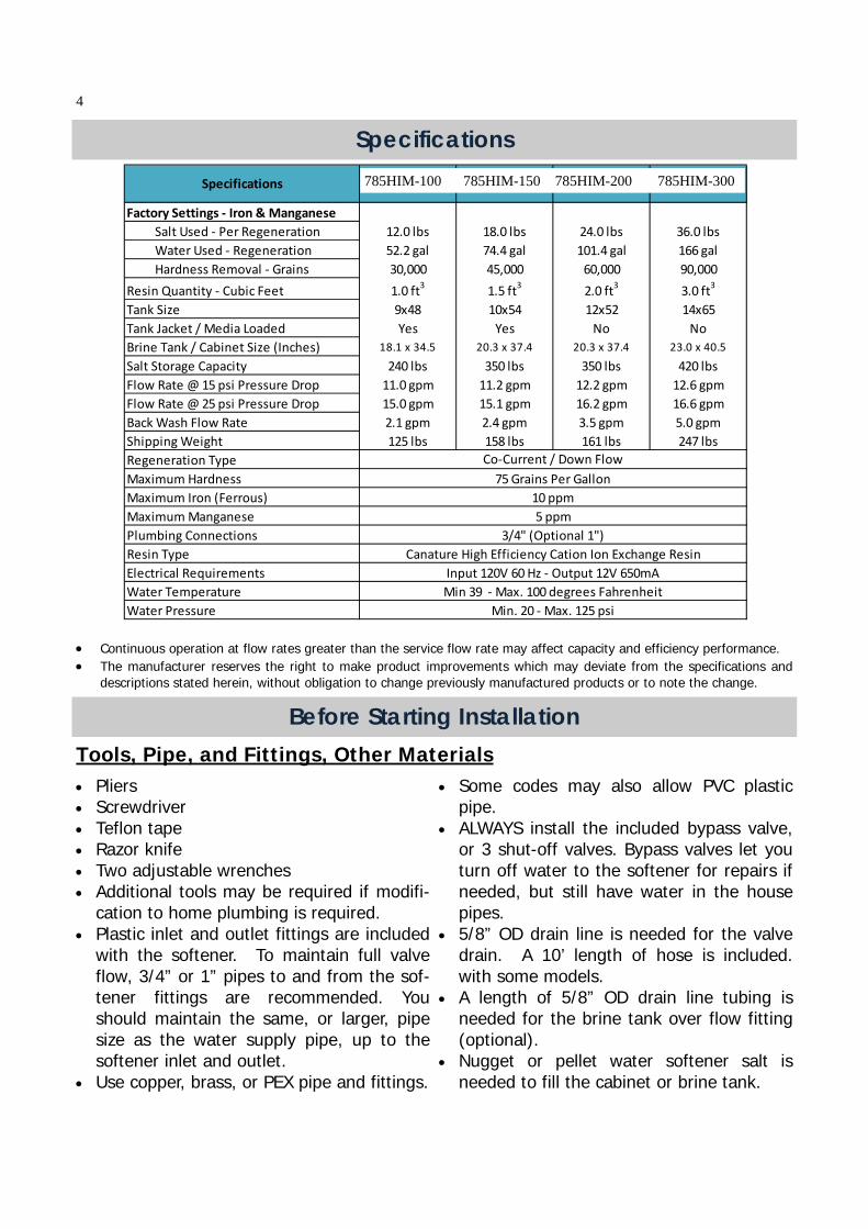
Factory Settings ‐ Iron & Manganese
Salt Used ‐ Per Regeneration 12.0 lbs 18.0 lbs 24.0 lbs 36.0 lbs
Water Used ‐ Regeneration 52.2 gal 74.4 gal 101.4 gal 166 gal
Hardness Removal ‐ Grains 30,000 45,000 60,000 90,000
Resin Quantity ‐ Cubic Feet 1.0 ft3
1.5 ft3
2.0 ft3
3.0 ft3
Tank Size 9x48 10x54 12x52 14x65
Tank Jacket / Media Loaded Yes Yes No No
Brine Tank / Cabinet Size (Inches) 18.1 x 34.5 20.3 x 37.4 20.3 x 37.4 23.0 x 40.5
Salt Storage Capacity 240 lbs 350 lbs 350 lbs 420 lbs
Flow Rate @ 15 psi Pressure Drop 11.0 gpm 11.2 gpm 12.2 gpm 12.6 gpm
Flow Rate @ 25 psi Pressure Drop 15.0 gpm 15.1 gpm 16.2 gpm 16.6 gpm
Back Wash Flow Rate 2.1 gpm 2.4 gpm 3.5 gpm 5.0 gpm
Shipping Weight 125 lbs 158 lbs 161 lbs 247 lbs
Regeneration Type
Maximum Hardness
Maximum Iron (Ferrous)
Maximum Manganese
Plumbing Connections
Resin Type
Electrical Requirements
Water Temperature
Water Pressure Min. 20 ‐ Max. 125 psi
Specifications
75 Grains Per Gallon
3/4" (Optional 1")
Canature High Efficiency Cation Ion Exchange Resin
Input 120V 60 Hz ‐ Output 12V 650mA
Min 39 ‐ Max. 100 degrees Fahrenheit
10 ppm
5 ppm
Co‐Current / Down Flow
585HIM‐100 585HIM‐150 585HIM‐200 585HIM‐300785HIM-100 785HIM-150 785HIM-200 785HIM-300
4
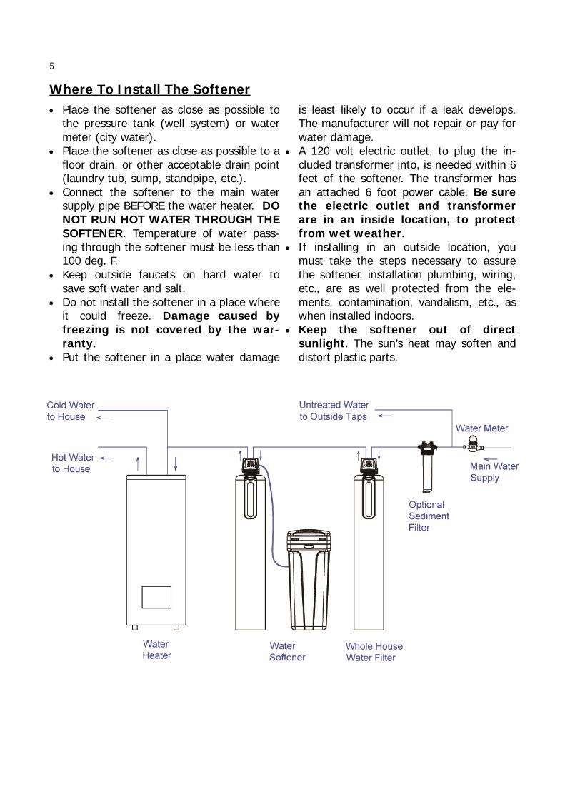
Place the softener as close as possible to the pressure tank (well system) or water meter (city water).
Place the softener as close as possible to a floor drain, or other acceptable drain point (laundry tub, sump, standpipe, etc.).
Connect the softener to the main water supply pipe BEFORE the water heater. DO NOT RUN HOT WATER THROUGH THE SOFTENER. Temperature of water pass-ing through the softener must be less than 100 deg. F.
Keep outside faucets on hard water to save soft water and salt.
Do not install the softener in a place where it could freeze. Damage caused by freezing is not covered by the war-ranty.
Put the softener in a place water damage
is least likely to occur if a leak develops. The manufacturer will not repair or pay for water damage.
A 120 volt electric outlet, to plug the in-cluded transformer into, is needed within 6 feet of the softener. The transformer has an attached 6 foot power cable. Be sure the electric outlet and transformer are in an inside location, to protect from wet weather.
If installing in an outside location, you must take the steps necessary to assure the softener, installation plumbing, wiring, etc., are as well protected from the ele-ments, contamination, vandalism, etc., as when installed indoors.
Keep the softener out of direct sunlight. The sun’s heat may soften and distort plastic parts.
Where To Install The Softener
5
1. If your hot water tank is electric, turn off the power to it to avoid damage to the element in the tank.
2. If you have a private well, turn the power off to the pump and then shut off the main wa-ter shut off valve. If you have municipal water, simply shut off the main valve. Go to the faucet, (preferably on the lowest floor of the house) turn on the cold water until all pres-sure is relieved and the flow of water stops.
3. Locate the softener tank and brine tank close to a drain where the system will be in-stalled. The surface should be clean and level.
4. Connect the inlet and outlet of the softener using appropriate fittings. Perform all plumb-ing according to local plumbing codes.
Use a ½” minimum pipe or tubing size for the drain line ON COPPER PLUMBING SYSTEMS BE SURE TO INSTALL A GROUNDING
WIRE BETWEEN THE INLET AND OUTLET PIPING TO MAINTAIN GROUND-ING.
Any solder joints near the valve must be done before connecting any piping to the valve. Always leave at least 6" (152 mm) between the valve and joints when soldering pipes that are connected to the valve. Failure to do this could cause damage to the valve. 5. Connect the drain hose (10 ft included) to the valve and secure it with a hose clamp (also
included). Run the drain hose to the nearest laundry tub or drain pipe. This can be ran up overhead or down along the floor. If running the drain line more than 20 ft overhead, it is recommended to increase the hose size to 3/4”. NEVER MAKE A DIRECT CONNEC-TION INTO A WASTE DRAIN. A PHYSICAL AIR GAP OF AT LEAST 1.5” SHOULD BE USED TO AVOID BACTERIA AND WASTEWATER TRAVELLING BACK THROUGH THE DRAIN LINE INTO THE SOFTENER.
6. Using the Allen Key (included), place the unit in the bypass position. Slowly turn on the main water supply. At the nearest cold treated water tap nearby remove the faucet screen, open the faucet and let water run a few minutes or until the system is free of any air or foreign material resulting from the plumbing work.
7. Make sure there are no leaks in the plumbing system before proceeding. Close the water tap when water runs clean.
8. Open the brine tank / cabinet salt lid and add water until there is approximately 3" (75 mm) of water in the tank. Do not add salt to the brine tank at this time.
9. Proceed to start up instructions. Note: The unit is not ready for service until you complete the start-up instruc-tions.
Installation Instructions 6
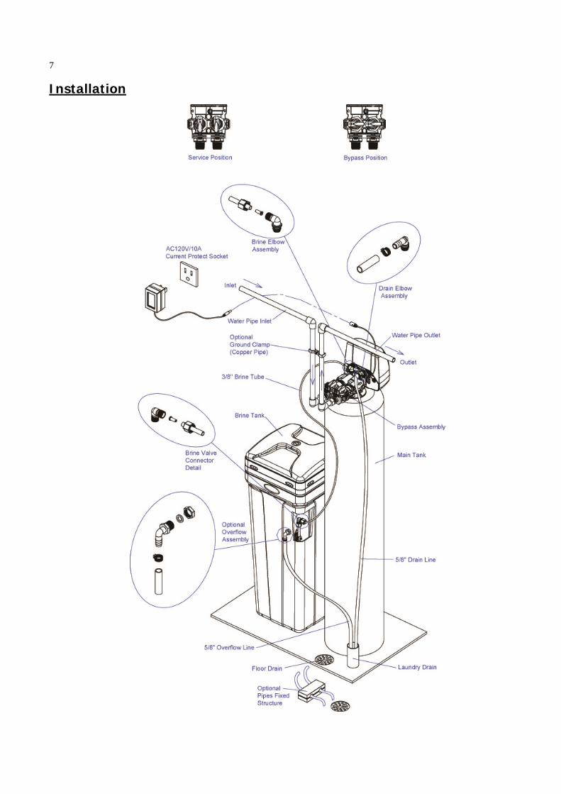
Installation
7
System Start-Up
1. Plug the power transformer into an ap-proved power source. Connect the power cord to the valve.
2. When power is supplied to the control, the screen will display “INITIALIZING WAIT PLEASE” while it finds the service position.
3. Manually step the valve past the BRINE position to the BACKWASH position. If screen is locked, press SETTINGS for 3 seconds to unlock. Press and hold the MANUL REGEN. Key for 3 seconds. Press any key to skip the BRINE cycle.
4. Once in the BACKWASH cycle, open the inlet on the bypass valve slowly and allow water to enter the unit. Allow all air to es-cape from the unit before turning the wa-ter on fully then allow water to run to drain for 3-4 minutes or until all media fines are washed out of the softener indi-
cated by clear water in the drain hose. 5. Press any button to advance to the RINSE
position. Check the drain line flow. Allow the water to run for 3-4 minutes or until the water is clear.
6. Press any button to advance to the REFILL position. Check that the valve is filling wa-ter into the brine tank. Allow the valve to refill for the full amount of time as dis-played on the screen to insure a proper brine solution for the next regeneration.
7. The valve will automatically advance to the SERVICE position. Open the outlet valve on the bypass, then open the nearest treated water faucet and allow the water to run until clear, close the tap and replace the faucet screen.
8. Add salt into the cabinet / brine tank. 9. Program unit.
Key Pad Configuration
Start-up Instructions
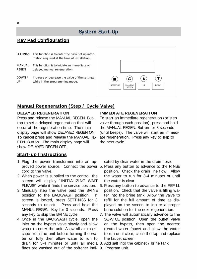
SETTINGS This function is to enter the basic set up infor‐mation required at the time of installation.
MANUAL REGEN
This function is to initiate an immediate or delayed manual regeneration.
DOWN / UP
Increase or decrease the value of the settings while in the programming mode.
DELAYED REGENERATION Press and release the MANUAL REGEN. But-ton to set a delayed regeneration that will occur at the regeneration time. The main display page will show DELAYED REGEN ON. To cancel press and release the MANUAL RE-GEN. Button. The main display page will show DELAYED REGEN OFF.
IMMEDIATE REGENERATION To start an immediate regeneration (or step valve through each position), press and hold the MANUAL REGEN. Button for 3 seconds (until beeps). The valve will start an immedi-ate regeneration. Press any key to skip to the next cycle.
Manual Regeneration (Step / Cycle Valve)
SETTINGS MANUAL REGEN
UP
DOWN
8
Programming Instructions
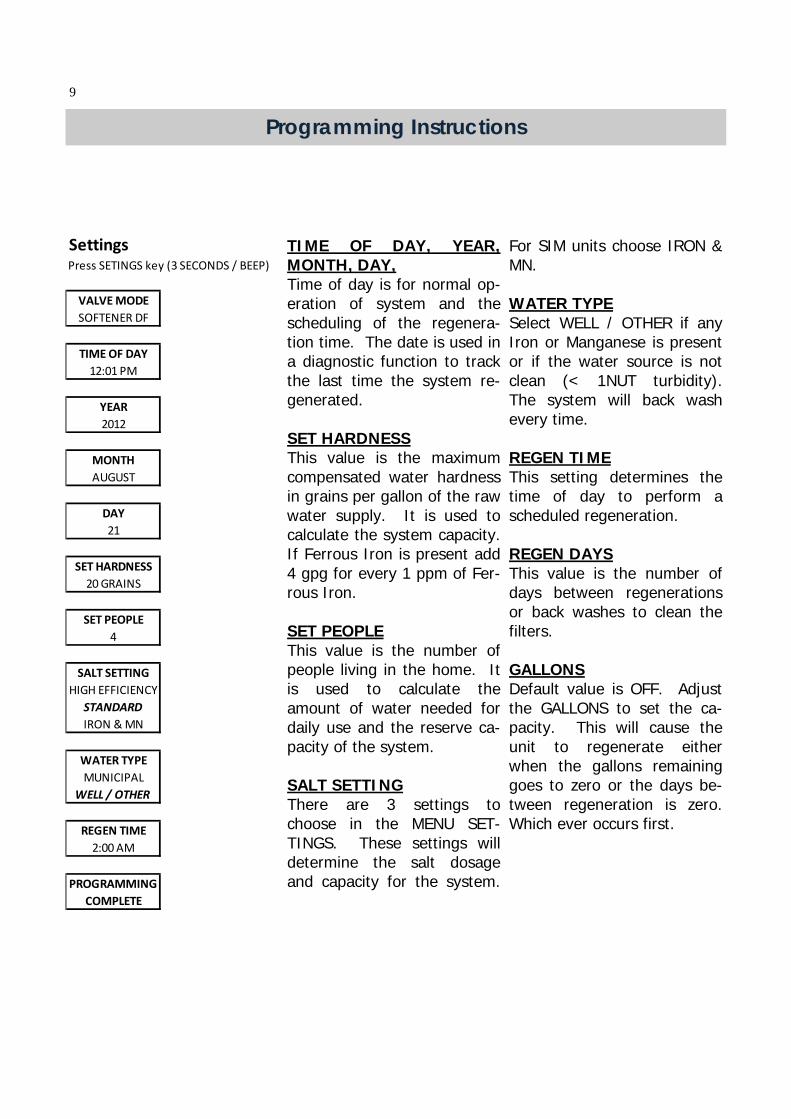
TIME OF DAY, YEAR, MONTH, DAY, Time of day is for normal op-eration of system and the scheduling of the regenera-tion time. The date is used in a diagnostic function to track the last time the system re-generated. SET HARDNESS This value is the maximum compensated water hardness in grains per gallon of the raw water supply. It is used to calculate the system capacity. If Ferrous Iron is present add 4 gpg for every 1 ppm of Fer-rous Iron. SET PEOPLE This value is the number of people living in the home. It is used to calculate the amount of water needed for daily use and the reserve ca-pacity of the system. SALT SETTING There are 3 settings to choose in the MENU SET-TINGS. These settings will determine the salt dosage and capacity for the system.
For SIM units choose IRON & MN. WATER TYPE Select WELL / OTHER if any Iron or Manganese is present or if the water source is not clean (< 1NUT turbidity). The system will back wash every time. REGEN TIME This setting determines the time of day to perform a scheduled regeneration. REGEN DAYS This value is the number of days between regenerations or back washes to clean the filters. GALLONS Default value is OFF. Adjust the GALLONS to set the ca-pacity. This will cause the unit to regenerate either when the gallons remaining goes to zero or the days be-tween regeneration is zero. Which ever occurs first.
SettingsPress SETINGS key (3 SECONDS / BEEP)
VALVE MODE
SOFTENER DF
TIME OF DAY
12:01 PM
YEAR
2012
MONTH
AUGUST
DAY
21
SET HARDNESS
20 GRAINS
SET PEOPLE
4
SALT SETTING
HIGH EFFICIENCY
STANDARD
IRON & MN
WATER TYPE
MUNICIPAL
WELL / OTHER
REGEN TIME
2:00 AM
PROGRAMMING
COMPLETE
9
Control Operation During A Power Failure In the event of a power failure, the valve will keep track of the time and day for 48 hours. The programmed settings are stored in a non-volatile memory and will not be lost during a power failure. If power fails while the unit is in regeneration, the valve will finish regenera-tion from the point it is at once power is restored. If the valve misses a scheduled regen-eration due to a power failure, it will queue a regeneration at the next regeneration time once power is restored.
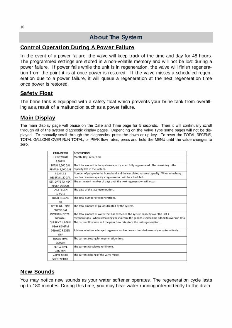
Main Display The main display page will pause on the Date and Time page for 5 seconds. Then it will continually scroll through all of the system diagnostic display pages. Depending on the Valve Type some pages will not be dis-played. To manually scroll through the diagnostics, press the down or up key. To reset the TOTAL REGENS, TOTAL GALLONS OVER RUN TOTAL, or PEAK flow rates, press and hold the MENU until the value changes to zero.
The brine tank is equipped with a safety float which prevents your brine tank from overfill-ing as a result of a malfunction such as a power failure.
Safety Float
New Sounds You may notice new sounds as your water softener operates. The regeneration cycle lasts up to 180 minutes. During this time, you may hear water running intermittently to the drain.
About The System
PARAMETER DESCRIPTION
JULY/17/2012
8:30 PM
TOTAL 1,500 GAL
REMAIN 1,200 GAL
PEOPLE 2
RESERVE 150 GAL
EST. DAYS TO NEXT
REGEN 06 DAYS
LAST REGEN
9/24/12
TOTAL REGENS
10
TOTAL GALLONS
001590 GAL
OVER RUN TOTAL
0500 GAL
CURRENT 1.5 GPM
PEAK 6.5 GPM
DELAYED REGEN
OFF
REGEN TIME
2:00 AM
REFILL TIME
3:00 MIN
VALVE MODE
SOFTENER UF
The total amount of water that has exceeded the system capacity over the last 4
regenerations. When remaining goes to zero, the gallons used will be added to over run total.
The current flow rate and the peak flow rate since the last regeneration.
Advises whether a delayed regeneration has been scheduled manually or automatically.
The current setting of the valve mode.
Month, Day, Year, Time
The current calculated refill time.
The current setting for regeneration time.
Number of people in the household and the calculated reserve capacity. When remaining
reaches reserve capacity a regeneration will be scheduled.
The total amount is the system capacity when fully regenerated. The remaining is the
capacity left in the system.
The estimated number of days until the next regeneration will occur.
The date of the last regeneration.
The total number of regenerations.
The total amount of gallons treated by the system.
10
Automatic Hard Water Bypass During Regeneration The regeneration cycle can last 30 to 180 minutes, after which soft water service will be re-stored. During regeneration, hard water is automatically bypassed for use in the household. Hot water should be used as little as possible during this time to prevent hard water from filling the water heater. This is why automatic regeneration is set for sometime during the night and manual regenerations should be performed when little or no water will be used in the household. Normal regeneration time is 2:00 AM.
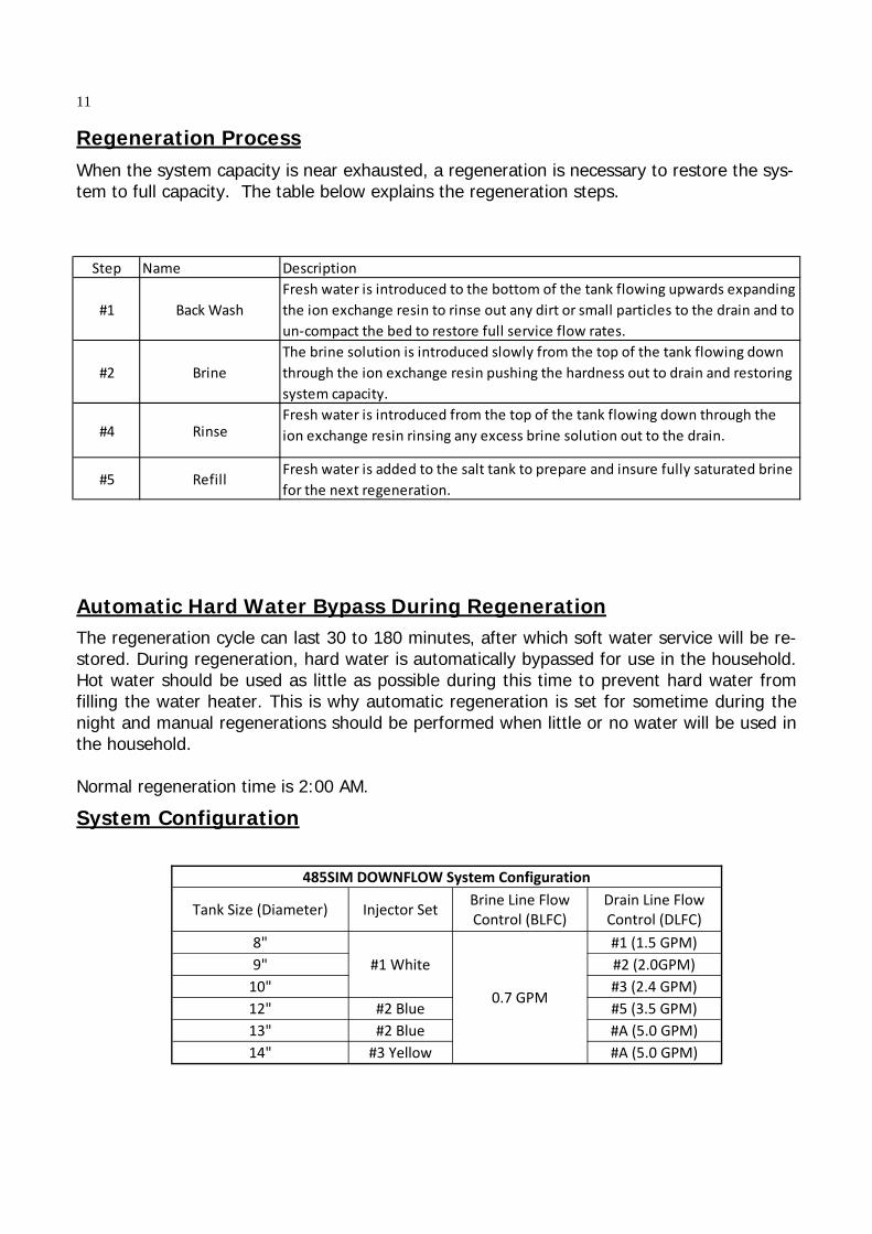
When the system capacity is near exhausted, a regeneration is necessary to restore the sys-tem to full capacity. The table below explains the regeneration steps.
Regeneration Process
System Configuration
Step Name Description
#1 Back Wash
Fresh water is introduced to the bottom of the tank flowing upwards expanding
the ion exchange resin to rinse out any dirt or small particles to the drain and to
un‐compact the bed to restore full service flow rates.
#2 Brine
The brine solution is introduced slowly from the top of the tank flowing down
through the ion exchange resin pushing the hardness out to drain and restoring
system capacity.
#4 RinseFresh water is introduced from the top of the tank flowing down through the
ion exchange resin rinsing any excess brine solution out to the drain.
#5 RefillFresh water is added to the salt tank to prepare and insure fully saturated brine
for the next regeneration.
485SIM DOWNFLOW System Configuration
Tank Size (Diameter) Injector Set Brine Line Flow Control (BLFC)
Drain Line Flow Control (DLFC)
8"
#1 White
0.7 GPM
#1 (1.5 GPM)
9" #2 (2.0GPM)
10" #3 (2.4 GPM)
12" #2 Blue #5 (3.5 GPM)
13" #2 Blue #A (5.0 GPM)
14" #3 Yellow #A (5.0 GPM)
11
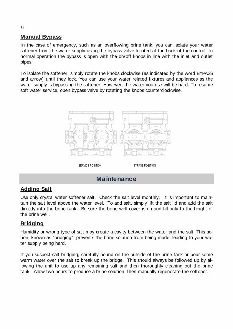
Manual Bypass
In the case of emergency, such as an overflowing brine tank, you can isolate your water softener from the water supply using the bypass valve located at the back of the control. In normal operation the bypass is open with the on/off knobs in line with the inlet and outlet pipes. To isolate the softener, simply rotate the knobs clockwise (as indicated by the word BYPASS and arrow) until they lock. You can use your water related fixtures and appliances as the water supply is bypassing the softener. However, the water you use will be hard. To resume soft water service, open bypass valve by rotating the knobs counterclockwise.
Maintenance Adding Salt Use only crystal water softener salt. Check the salt level monthly. It is important to main-tain the salt level above the water level. To add salt, simply lift the salt lid and add the salt directly into the brine tank. Be sure the brine well cover is on and fill only to the height of the brine well.
Bridging Humidity or wrong type of salt may create a cavity between the water and the salt. This ac-tion, known as “bridging”, prevents the brine solution from being made, leading to your wa-ter supply being hard. If you suspect salt bridging, carefully pound on the outside of the brine tank or pour some warm water over the salt to break up the bridge. This should always be followed up by al-lowing the unit to use up any remaining salt and then thoroughly cleaning out the brine tank. Allow two hours to produce a brine solution, then manually regenerate the softener.
12
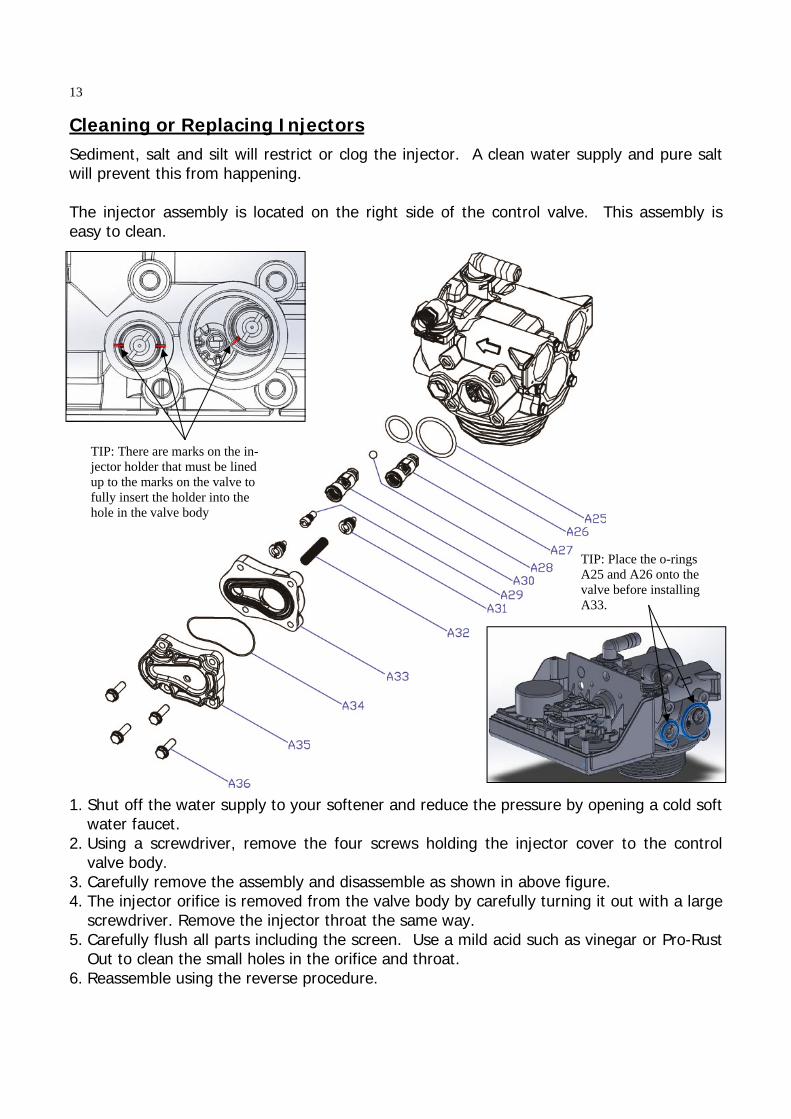
Cleaning or Replacing Injectors Sediment, salt and silt will restrict or clog the injector. A clean water supply and pure salt will prevent this from happening. The injector assembly is located on the right side of the control valve. This assembly is easy to clean.
1. Shut off the water supply to your softener and reduce the pressure by opening a cold soft water faucet.
2. Using a screwdriver, remove the four screws holding the injector cover to the control valve body.
3. Carefully remove the assembly and disassemble as shown in above figure. 4. The injector orifice is removed from the valve body by carefully turning it out with a large
screwdriver. Remove the injector throat the same way. 5. Carefully flush all parts including the screen. Use a mild acid such as vinegar or Pro-Rust
Out to clean the small holes in the orifice and throat. 6. Reassemble using the reverse procedure.
TIP: There are marks on the in-jector holder that must be lined up to the marks on the valve to fully insert the holder into the hole in the valve body
TIP: Place the o-rings A25 and A26 onto the valve before installing A33.
13
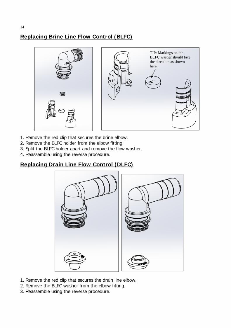
Replacing Brine Line Flow Control (BLFC)
1. Remove the red clip that secures the brine elbow. 2. Remove the BLFC holder from the elbow fitting. 3. Split the BLFC holder apart and remove the flow washer. 4. Reassemble using the reverse procedure.
TIP: Markings on the BLFC washer should face the direction as shown here.
Replacing Drain Line Flow Control (DLFC)
1. Remove the red clip that secures the drain line elbow. 2. Remove the BLFC washer from the elbow fitting. 3. Reassemble using the reverse procedure.
14
Care of Your System To retain the attractive appearance of your new water softener, clean occasionally with mild soap solution. Do not use abrasive cleaners, ammonia or solvents. Never subject your sof-tener to freezing or to temperatures above 100°F.
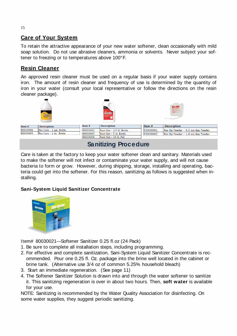
Resin Cleaner An approved resin cleaner must be used on a regular basis if your water supply contains iron. The amount of resin cleaner and frequency of use is determined by the quantity of iron in your water (consult your local representative or follow the directions on the resin cleaner package).
Sanitizing Procedure Care is taken at the factory to keep your water softener clean and sanitary. Materials used to make the softener will not infect or contaminate your water supply, and will not cause bacteria to form or grow. However, during shipping, storage, installing and operating, bac-teria could get into the softener. For this reason, sanitizing as follows is suggested when in-stalling. Sani-System Liquid Sanitizer Concentrate Item# 80030021—Softener Sanitizer 0.25 fl.oz (24 Pack) 1. Be sure to complete all installation steps, including programming. 2. For effective and complete sanitization, Sani-System Liquid Sanitizer Concentrate is rec-
ommended. Pour one 0.25 fl. Oz. package into the brine well located in the cabinet or brine tank. (Alternative use 3/4 oz of common 5.25% household bleach)
3. Start an immediate regeneration. (See page 11) 4. The Softener Sanitizer Solution is drawn into and through the water softener to sanitize
it. This sanitizing regeneration is over in about two hours. Then, soft water is available for your use.
NOTE: Sanitizing is recommended by the Water Quality Association for disinfecting. On some water supplies, they suggest periodic sanitizing.
15
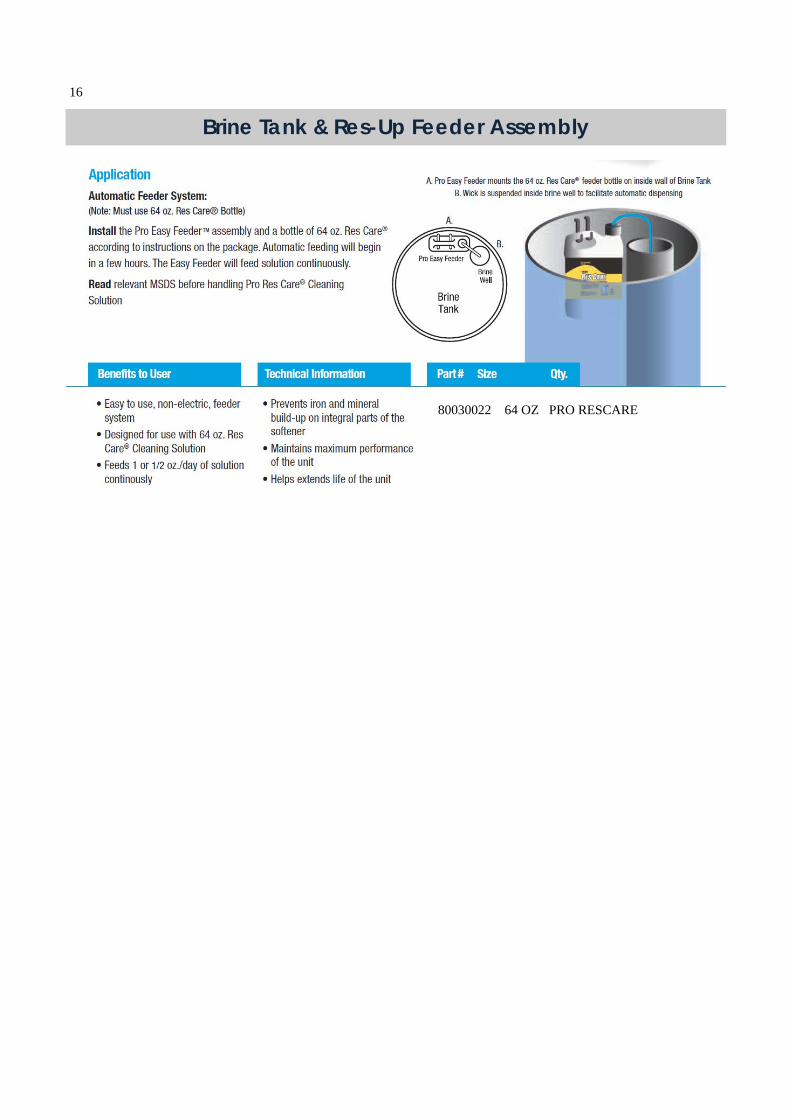
Brine Tank & Res-Up Feeder Assembly
80030022 64 OZ PRO RESCARE
16
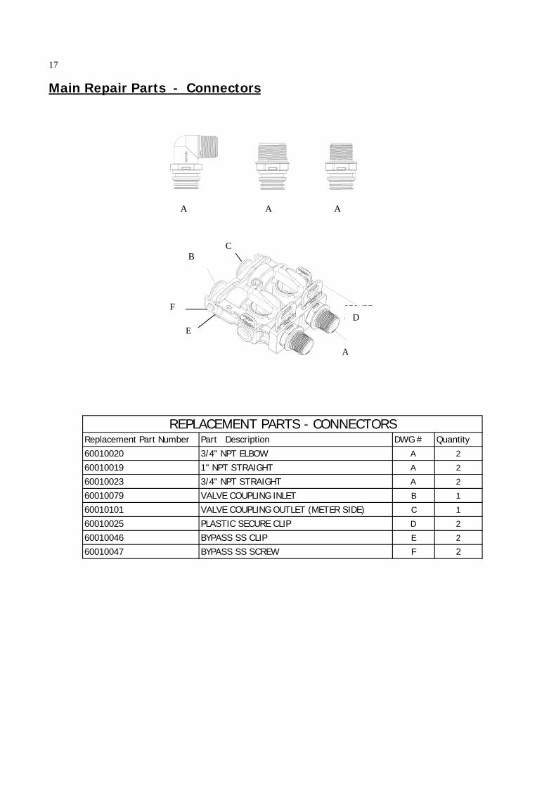
Main Repair Parts - Connectors
A A A
B
D F
E
A
C
Replacement Part Number Part Description DWG # Quantity60010020 3/4" NPT ELBOW A 2
60010019 1" NPT STRAIGHT A 2
60010023 3/4" NPT STRAIGHT A 2
60010079 VALVE COUPLING INLET B 1
60010101 VALVE COUPLING OUTLET (METER SIDE) C 1
60010025 PLASTIC SECURE CLIP D 2
60010046 BYPASS SS CLIP E 2
60010047 BYPASS SS SCREW F 2
REPLACEMENT PARTS - CONNECTORS
17
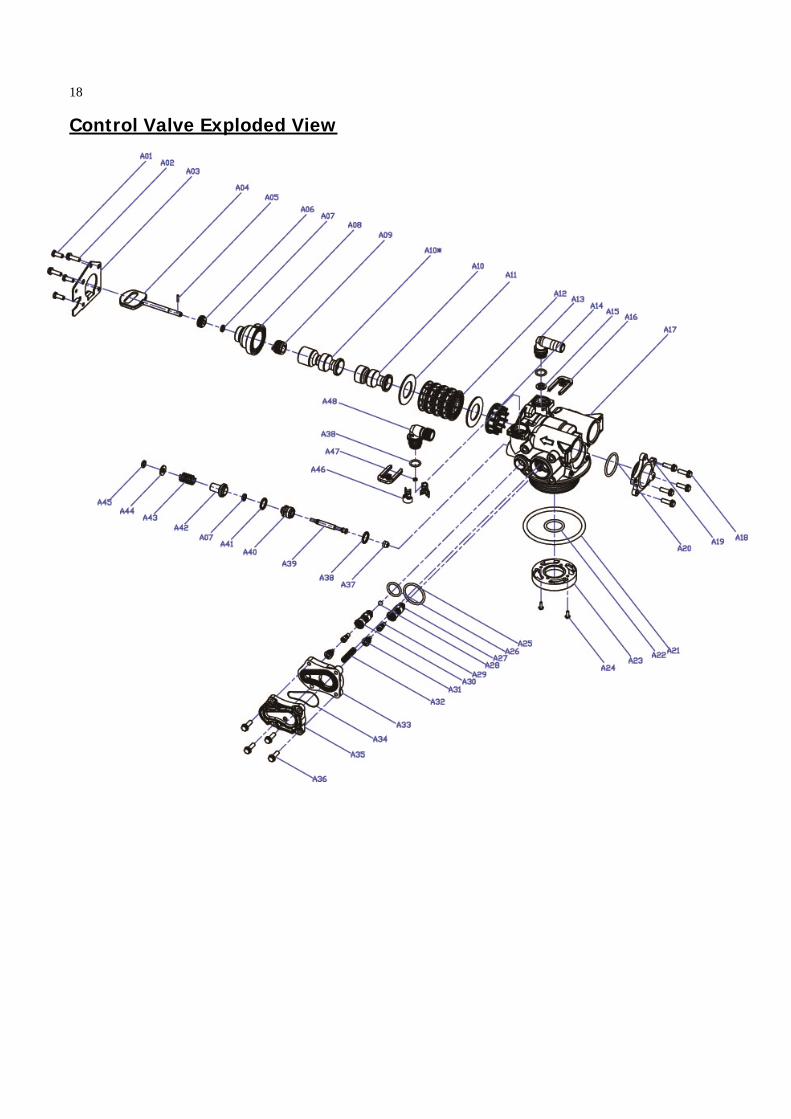
Control Valve Exploded View
18
Control Valve Parts List
Replacement Part Number
MFG Part Number Part Description DWG # Quantity
5056087 Screw-M5x12(Hexagon) A01 3
5056088 Screw-M5x16(Hexagon With Washer) A02 25056047 End Plug Retainer A03 1
5031016 BNT85HE Piston Rod A04 15056097 Piston Pin A05 1
5031015 BNT85HE Quad Ring Plug Cover A06 15056070 Quad Ring A07 25031011 BNT85HE End Plug A08 15031014 BNT85HE Piston Retainer A09 1
5057001 BNT85HE Piston(Electrical Downflow) A10 1
5056073 Seal A11 5
5056021 Spacer A12 4
5010082 Drain Fitting-B A13 1
5031005 BNT85HE Spacer A14 1
5056186 DLFC-2# A15 1
5056172 Secure Clip-s A16 2
5031002 BNT85HE Valve Body A17 1
5056508 Screw-M5x12(Hexagon With Washer) A18 5
5030004 BNT85 End Cover A19 1
5030013 O-Ring-¢30×2.65 A20 1
5056063 O-Ring-¢78.74×5.33 A21 1
26010103 O-Ring-¢25×3.55 A22 1
7060007 Valve Bottom Connector A23 1
13000426 Screw-ST2.9X13(Large Washer) A24 2
5031022 O-Ring-¢32×3 A25 1
5031021 O-Ring-¢18×3 A26 1
5031013 Injector Plug Body A27 1
30110007 Plastic Ball ¢6 A28 1
30040089 Injector Throat A29 2
5031012 BNT85HE Injector Fixed Sleeve A30 1
30040090 Injector Nozzle A31 2
5056103 Injector Screen A32 1
5031003 BNT85HE Injector Cover Body A33 1
5031018 O-Ring-¢40×2.65 A34 1
5031004 BNT85HE Injector Cover Cap A35 1
5031027 Screw-M5x25(Hexagon With Washer) A36 4
5056075 Seal Mat A37 1
5056134 O-Ring-¢12×2 A38 3
5056054 Injector Stem A39 1
5056031 Injector Spacer A40 1
5056081 O-Ring-¢12.5×1.8 A41 1
5056030 Injector Cap A42 1
5056093 Injector Screen A43 1
5010049 Special Washer A44 1
5056105 Retaining Ring A45 1
5031010 BNT85HE BLFC Fixed Sleeve A46 2
5056076 BLFC-2# A47 1
5005629 Injector Fitting(3/8".Elbow) A48 1
785 CONTROL VALVE (DOWNFLOW)
19
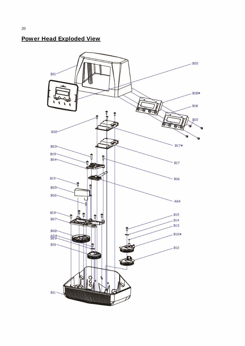
Power Head Exploded View
20
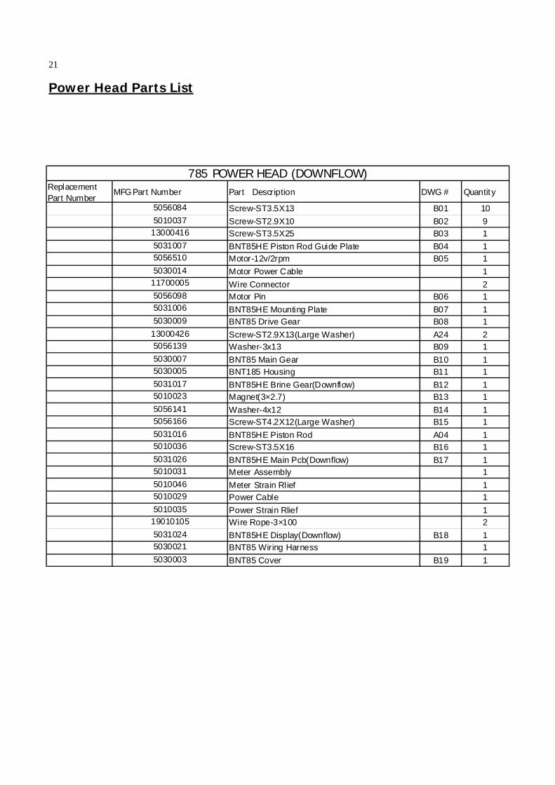
Power Head Parts List
Replacement Part Number
MFG Part Number Part Description DWG # Quantity
5056084 Screw-ST3.5X13 B01 10
5010037 Screw-ST2.9X10 B02 913000416 Screw-ST3.5X25 B03 1
5031007 BNT85HE Piston Rod Guide Plate B04 15056510 Motor-12v/2rpm B05 1
5030014 Motor Power Cable 111700005 Wire Connector 25056098 Motor Pin B06 15031006 BNT85HE Mounting Plate B07 15030009 BNT85 Drive Gear B08 1
13000426 Screw-ST2.9X13(Large Washer) A24 25056139 Washer-3x13 B09 1
5030007 BNT85 Main Gear B10 15030005 BNT185 Housing B11 1
5031017 BNT85HE Brine Gear(Downflow) B12 15010023 Magnet(3×2.7) B13 1
5056141 Washer-4x12 B14 15056166 Screw-ST4.2X12(Large Washer) B15 1
5031016 BNT85HE Piston Rod A04 15010036 Screw-ST3.5X16 B16 1
5031026 BNT85HE Main Pcb(Downflow) B17 15010031 Meter Assembly 1
5010046 Meter Strain Rlief 15010029 Power Cable 1
5010035 Power Strain Rlief 119010105 Wire Rope-3×100 2
5031024 BNT85HE Display(Downflow) B18 15030021 BNT85 Wiring Harness 1
5030003 BNT85 Cover B19 1
785 POWER HEAD (DOWNFLOW)
21
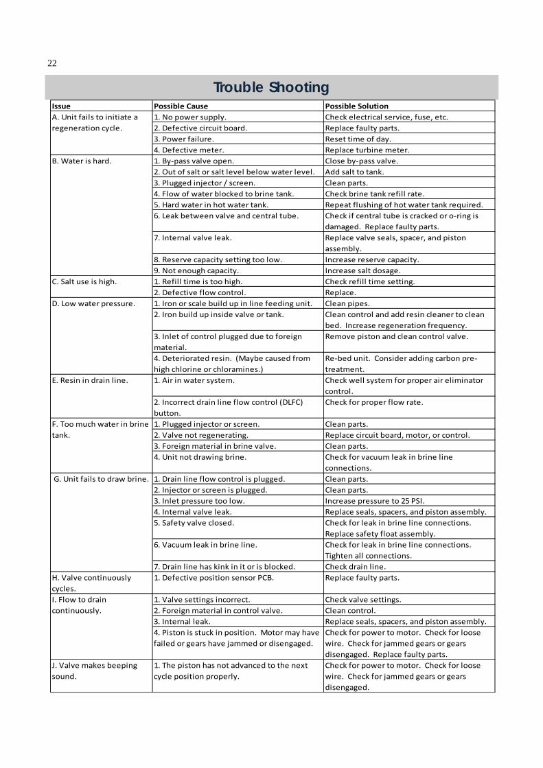
Trouble Shooting Issue Possible Cause Possible Solution
1. No power supply. Check electrical service, fuse, etc.
2. Defective circuit board. Replace faulty parts.
3. Power failure. Reset time of day.
4. Defective meter. Replace turbine meter.
1. By‐pass valve open. Close by‐pass valve.
2. Out of salt or salt level below water level. Add salt to tank.
3. Plugged injector / screen. Clean parts.
4. Flow of water blocked to brine tank. Check brine tank refill rate.
5. Hard water in hot water tank. Repeat flushing of hot water tank required.
6. Leak between valve and central tube. Check if central tube is cracked or o‐ring is
damaged. Replace faulty parts.
7. Internal valve leak. Replace valve seals, spacer, and piston
assembly.
8. Reserve capacity setting too low. Increase reserve capacity.
9. Not enough capacity. Increase salt dosage.
1. Refill time is too high. Check refill time setting.
2. Defective flow control. Replace.
1. Iron or scale build up in line feeding unit. Clean pipes.
2. Iron build up inside valve or tank. Clean control and add resin cleaner to clean
bed. Increase regeneration frequency.
3. Inlet of control plugged due to foreign
material.
Remove piston and clean control valve.
4. Deteriorated resin. (Maybe caused from
high chlorine or chloramines.)
Re‐bed unit. Consider adding carbon pre‐
treatment.
1. Air in water system. Check well system for proper air eliminator
control.
2. Incorrect drain line flow control (DLFC)
button.
Check for proper flow rate.
1. Plugged injector or screen. Clean parts.
2. Valve not regenerating. Replace circuit board, motor, or control.
3. Foreign material in brine valve. Clean parts.
4. Unit not drawing brine. Check for vacuum leak in brine line
connections.
1. Drain line flow control is plugged. Clean parts.
2. Injector or screen is plugged. Clean parts.
3. Inlet pressure too low. Increase pressure to 25 PSI.
4. Internal valve leak. Replace seals, spacers, and piston assembly.
5. Safety valve closed. Check for leak in brine line connections.
Replace safety float assembly.
6. Vacuum leak in brine line. Check for leak in brine line connections.
Tighten all connections.
7. Drain line has kink in it or is blocked. Check drain line.
H. Valve continuously
cycles.
1. Defective position sensor PCB. Replace faulty parts.
1. Valve settings incorrect. Check valve settings.
2. Foreign material in control valve. Clean control.
3. Internal leak. Replace seals, spacers, and piston assembly.
4. Piston is stuck in position. Motor may have
failed or gears have jammed or disengaged.
Check for power to motor. Check for loose
wire. Check for jammed gears or gears
disengaged. Replace faulty parts.
J. Valve makes beeping
sound.
1. The piston has not advanced to the next
cycle position properly.
Check for power to motor. Check for loose
wire. Check for jammed gears or gears
disengaged.
I. Flow to drain
continuously.
G. Unit fails to draw brine.
A. Unit fails to initiate a
regeneration cycle.
B. Water is hard.
E. Resin in drain line.
C. Salt use is high.
D. Low water pressure.
F. Too much water in brine
tank.
22
Warranty Canature WaterGroup warrants that your new water conditioner is built of quality mate-rial and workmanship. When properly installed and maintained, it will give years of trouble free service.
Seven Year Complete Parts Guarantee Canature WaterGroup will replace any part which fails within 84 months from date of manufacture, as indicated by the serial number, provided the failure is due to a defect in material or workmanship. The only exception shall be when proof of purchase or installa-tion is provided and then the warranty period shall be from the date thereof.
Life Time Warranty on Mineral Tanks and Brine Tanks Canature WaterGroup will provide a replacement mineral tank or brine tank to any original equipment purchaser in possession of a tank that fails provided that the water conditioner is at all times operated in accordance with specifications and not subject to freezing.
General Conditions Damage to any part of this water conditioner or filter as a result of misuse, misapplication, neglect, alteration, accident, installation or operation contrary to our printed instructions, damage to ion exchange resin and seals caused by chlorine / chloramines in the water sup-ply, or damage caused by any force of nature is not covered in this warranty. We will repair or replace defective parts if our warranty department determines it to be defective under the terms of this warranty. Canature WaterGroup assumes no responsibility for consequen-tial damage, la-bour or expense incurred as a result of a defect or failure.
23