Embed Size (px)
Citation preview
792 IEEE TRANSACTIONS ON COMPONENTS, PACKAGING AND MANUFACTURING TECHNOLOGY, VOL. 7, NO. 5, MAY 2017
Liquid Crystal Leaky-Wave Antennas WithDispersion Sensitivity Enhancement
Shuang Ma, Guo-Hui Yang, Member, IEEE, Daniel Erni, Member, IEEE, Fan-Yi Meng, Senior Member, IEEE,Lei Zhu, Qun Wu, Senior Member, IEEE, and Jia-Hui Fu, Senior Member, IEEE
Abstract— A novel design, fabrication, and packaging tech-nology is proposed for liquid crystal (LC)-based beam-scanningleaky-wave antennas (LWAs). Different from conventional ones,extra dispersion sensitivity enhancement (DSE) components areintroduced to increase the slope of effective phase constant versusfrequency of LWAs and, hence, the beam scanning range. CSTMW Studio software package is used to validate the designmethod. It is shown that, by adding the DSE components, theelectrical beam scanning range is extended by more than 56%in the Ku satellite communication band, where good impedancematching and balanced condition are kept for both extremetuning states of LCs. Prototypes of the designed LC-compositeright/left-handed LWAs with and without the DSE componentsare fabricated and measured. The fabrication methodology incor-porating printed circuit board and precision metal processingtechnology ensures the mechanical stability, flexible design,perfect packaging, and low cost. Finally, the feature-selectivevalidation technique validates that the measured and simulatedresults are in good agreement.
Index Terms— Beam scanning, composite right/left-handed (CRLH), dispersion sensitivity enhancement (DSE),fabrication methodology, leaky-wave antenna (LWA), liquidcrystal (LC).
I. INTRODUCTION
LEAKY-WAVE antennas (LWAs) have been widely inves-tigated in the past decades due to their unique charac-
teristics, such as narrow and directive beams, comparativelylow profile, as well as an inherently simple feeding network[1]–[3]. Particularly, LWAs with beam steering capabilityemployed in the Ku satellite communication band are ableto increase the channel capacity significantly and improve
Manuscript received December 5, 2016; revised January 20, 2017; acceptedFebruary 28, 2017. Date of publication April 4, 2017; date of current versionMay 15, 2017. This work was supported in part by the National NaturalScience Fund of China under Grant 61671180 and Grant 61501275, in partby the Science Foundation Project of Heilongjiang Province of China, underGrant QC2015073, and in part by the Deutsche Forschungsgemeinschaft inthe framework of DFG CRC/TRR 196 MARIE. Recommended for publicationby Associate Editor A. Orlandi upon evaluation of reviewers’ comments.(Corresponding author: Fan-Yi Meng.)
S. Ma, G.-H. Yang, F.-Y. Meng, Q. Wu, and J.-H. Fu are with theDepartment of Microwave Engineering, Harbin Institute of Technology,Harbin 150001, China (e-mail: [email protected]; [email protected];[email protected]; [email protected]; [email protected]).
D. Erni is with the Laboratory for General and Theoretical ElectricalEngineering (ATE), Center for Nanointegration Duisburg–Essen (CENIDE),Faculty of Engineering, University of Duisburg–Essen, 47048 Duisburg,Germany (e-mail: [email protected]).
L. Zhu is with the Institute of Communication and Electronics Engi-neering, Qiqihar University, Qiqihar 161006, China (e-mail: [email protected])
Color versions of one or more of the figures in this paper are availableonline at http://ieeexplore.ieee.org.
Digital Object Identifier 10.1109/TCPMT.2017.2683529
communication quality. While compared to the phased-arrayantennas, LWAs provide a simple solution with compact size,low cost, and ease of integration. However, traditional LWAsare not able to steer beams for a fixed frequency; thus,they need a wide frequency band and waste the increasinglylimited spectrum resources [4]–[6]. To solve this issue, fixed-frequency LWAs with tunable beams are investigated adoptingferrite, varactor, and liquid crystal (LC). The ferrite is widelyapplied in tunable microwave devices with high tuning speedand wide tuning performance, but its loss is very high [7], [8].On the other hand, varactors are taken as substitution in somecases for their relatively low loss and flexible mechanism [9],[10], but their operating frequency is usually limited below 10GHz due to the large parasitics of packaging.
LCs are a potential candidate for tunable LWAs at highfrequency due to their controllable dielectric parameters andlow loss property. The relative permittivity of LCs can bedescribed in terms of the order tensor, normally a uniaxialtensor with nonzero principal components !r! and !r// corre-sponding to the relative permittivity in the normal and paralleldirections of the director with respect to the applied biasfield, respectively [11]. The continuously variable permittivityexhibited by LCs leads to the development of reconfigurableantennas and microwave devices [12]–[14]. In the case of LCs-based LWAs, as the permittivity of LCs is tuned by a biaselectric field (or voltage), the phase constant and radiationdirection of LWAs can be steered [15]–[18].
However, the tunable LC-LWAs suffer from a narrow beamscanning range due to the restricted tunability of the LCpermittivity. This phenomenon seriously affects the qualityof satellite communication, which leads to the LC-LWAsbeing difficult to be widely applied in practice. For instance,the beam-scanning angle range of LC-composite right/left-handed (CRLH) LWAs only achieves 14° and 15° at 26.7 GHzin [15] and [17], respectively. Although the scanning range wasfurther extended to 40° by optimizing the feeding structurein [16], there is still lack of a general method to enlarge thebeam scanning range of LC-LWAs. Therefore, how to improvethe scanning range of the Ku-band LC-LWAs has become akey problem to be urgently solved.
Moreover, the LCs are liquid materials, which leads tocomplicated design and difficult packaging for microwavecomponents. Most of the existing LC microwave devices areprocessed by microelectronic technology [15]–[18], whichmakes the project of the microwave devices limited andincreases the process cost [19].
From this point, in this paper, we propose a novel dis-persion sensitivity enhancement (DSE) method to enlarge
2156-3950 © 2017 IEEE. Personal use is permitted, but republication/redistribution requires IEEE permission.See http://www.ieee.org/publications_standards/publications/rights/index.html for more information.
MA et al.: LIQUID CRYSTAL LEAKY-WAVE ANTENNAS WITH DISPERSION SENSITIVITY ENHANCEMENT 793
the beam scanning range of CRLH-LWAs. The LCs areintroduced and packaged through printed circuit board (PCB)and precision metal processing technology. This new typeof fabrication methodology ensures the LC components’ lowcost and the mechanical stability. Moreover, the electricalbeam scanning range is enhanced by the DSE method.Theoretical predictions, numerical simulation results, andexperimental results are in good agreement. The approachpresented in this paper offers a new way for the designfabrication and packaging of wide-angle beam-scanningLC-CRLH-LWAs.
II. THEORETICAL DESCRIPTION FOR DSE METHOD
For CRLH-LWAs, the main beam direction " is deter-mined by the phase constant # of the guided wave structure.Let us assume that the maximum and minimum tunableeffective permittivities of the LCs correspond to the phaseconstants #1 and #2, and the main beam direction "1 and "2of the LC-CRLH-LWA, respectively. Thus, the electrical beamscanning range of the LC-CRLH-LWA can be calculated by
$" = "1 " "2 = arcsin#1
k0" arcsin
#2
k0(1)
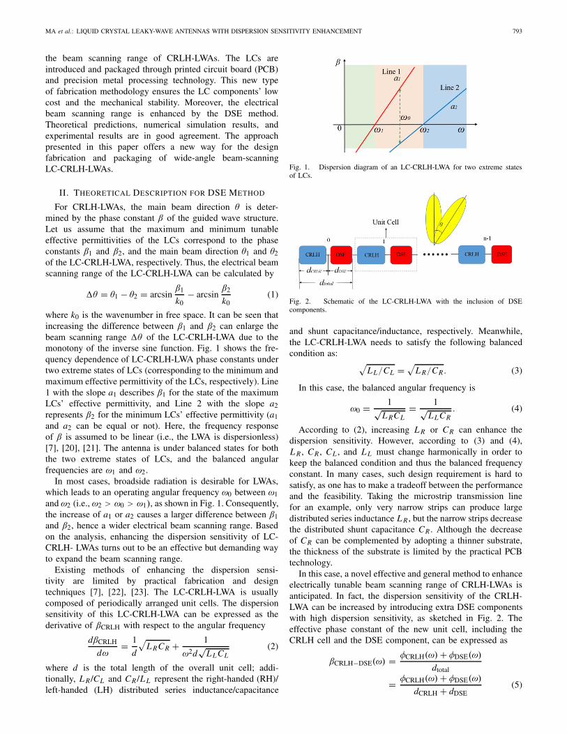
where k0 is the wavenumber in free space. It can be seen thatincreasing the difference between #1 and #2 can enlarge thebeam scanning range $" of the LC-CRLH-LWA due to themonotony of the inverse sine function. Fig. 1 shows the fre-quency dependence of LC-CRLH-LWA phase constants undertwo extreme states of LCs (corresponding to the minimum andmaximum effective permittivity of the LCs, respectively). Line1 with the slope a1 describes #1 for the state of the maximumLCs’ effective permittivity, and Line 2 with the slope a2represents #2 for the minimum LCs’ effective permittivity (a1and a2 can be equal or not). Here, the frequency responseof # is assumed to be linear (i.e., the LWA is dispersionless)[7], [20], [21]. The antenna is under balanced states for boththe two extreme states of LCs, and the balanced angularfrequencies are %1 and %2.
In most cases, broadside radiation is desirable for LWAs,which leads to an operating angular frequency %0 between %1and %2 (i.e., %2 > %0 > %1), as shown in Fig. 1. Consequently,the increase of a1 or a2 causes a larger difference between #1and #2, hence a wider electrical beam scanning range. Basedon the analysis, enhancing the dispersion sensitivity of LC-CRLH- LWAs turns out to be an effective but demanding wayto expand the beam scanning range.
Existing methods of enhancing the dispersion sensi-tivity are limited by practical fabrication and designtechniques [7], [22], [23]. The LC-CRLH-LWA is usuallycomposed of periodically arranged unit cells. The dispersionsensitivity of this LC-CRLH-LWA can be expressed as thederivative of #CRLH with respect to the angular frequency
d#CRLH
d%= 1
d
!L RCR + 1
%2d#
L LCL(2)
where d is the total length of the overall unit cell; addi-tionally, L R /CL and CR /L L represent the right-handed (RH)/left-handed (LH) distributed series inductance/capacitance
Fig. 1. Dispersion diagram of an LC-CRLH-LWA for two extreme statesof LCs.
Fig. 2. Schematic of the LC-CRLH-LWA with the inclusion of DSEcomponents.
and shunt capacitance/inductance, respectively. Meanwhile,the LC-CRLH-LWA needs to satisfy the following balancedcondition as:
!L L/CL =
!L R/CR . (3)
In this case, the balanced angular frequency is
%0 = 1#L RCL
= 1#L LCR
. (4)
According to (2), increasing L R or CR can enhance thedispersion sensitivity. However, according to (3) and (4),L R , CR , CL , and L L must change harmonically in order tokeep the balanced condition and thus the balanced frequencyconstant. In many cases, such design requirement is hard tosatisfy, as one has to make a tradeoff between the performanceand the feasibility. Taking the microstrip transmission linefor an example, only very narrow strips can produce largedistributed series inductance L R , but the narrow strips decreasethe distributed shunt capacitance CR . Although the decreaseof CR can be complemented by adopting a thinner substrate,the thickness of the substrate is limited by the practical PCBtechnology.
In this case, a novel effective and general method to enhanceelectrically tunable beam scanning range of CRLH-LWAs isanticipated. In fact, the dispersion sensitivity of the CRLH-LWA can be increased by introducing extra DSE componentswith high dispersion sensitivity, as sketched in Fig. 2. Theeffective phase constant of the new unit cell, including theCRLH cell and the DSE component, can be expressed as
#CRLH"DSE(%) = &CRLH(%) + &DSE(%)
dtotal
= &CRLH(%) + &DSE(%)
dCRLH + dDSE(5)
794 IEEE TRANSACTIONS ON COMPONENTS, PACKAGING AND MANUFACTURING TECHNOLOGY, VOL. 7, NO. 5, MAY 2017
where &CRLH(%) and &DSE(%) are the insertion phase shifts ofthe original CRLH cell and the DSE component, respectively.dCRLH and dDSE are the lengths of the CRLH cell and theDSE component, respectively, and dtotal is the total length ofone CRLH cell and one DSE component.
Furthermore, the dispersion sensitivity of the CRLH-LWAwith the DSE component can be derived as
# $CRLH"DSE(%) = &$
CRLH(%) + &$DSE(%)
dCRLH + dDSE. (6)
Consequently
# $CRLH"DSE(%)
# $CRLH(%)
= 1 + &$DSE(%)/&$
CRLH(%)
1 + dDSE/dCRLH. (7)
By (7), if the DSE component has both a sufficiently largephase change rate and a short length simultaneously, theCRLH-LWA with DSE components will have larger dispersionsensitivity than the original one, leading to a wider beamscanning range. In addition, considering practical requirementsfor the performance of wireless systems, the DSE componentalso needs to fulfill the following requirements.
1) The DSE component should satisfy the impedancematching condition in an as-wide-as-possible frequencyband.
2) The phase change rate &$DSE(%) of the DSE component
has to be a positive constant a to guarantee the linearityof the DSE component, which is expressed by
&$DSE(%) = a. (8)
3) The insertion phase shift &DSE(%) of the DSE com-ponent must be 2k' (k is a positive integer) to retainthe balanced frequency of the original LC-CRLH-LWA;thus, there is
&DSE(%0) = 2k'. (9)
Solving (8) and (9) and assuming &DSE(0) = &0 leads to
&DSE(%) = a(% " %0) + 2k' (10)
a = &DSE(%0) " &0
%0. (11)
It is worth noting that although the above-mentionedrequirements seem harsh, it can be easily achieved by a mean-der transmission line structure. According to [24] and [25],the meander line can be used as a kind of miniaturized phaseshifter with excellent performances, such as broad bandwidth,short length, and large phase shift, which exactly fits therequirements of the DSE component.
III. DESIGN OF LC-CRLH-LWA WITH THE DSECOMPONENT
A. LC-CRLH-LWA Without the DSE Component
In order to demonstrate the efficiency of the proposed DSEmethod, an LC-CRLH-LWA without the DSE component isdesigned at first. It is constituted by concatenating eight unitcells, as illustrated in Fig. 3(a) and (b).
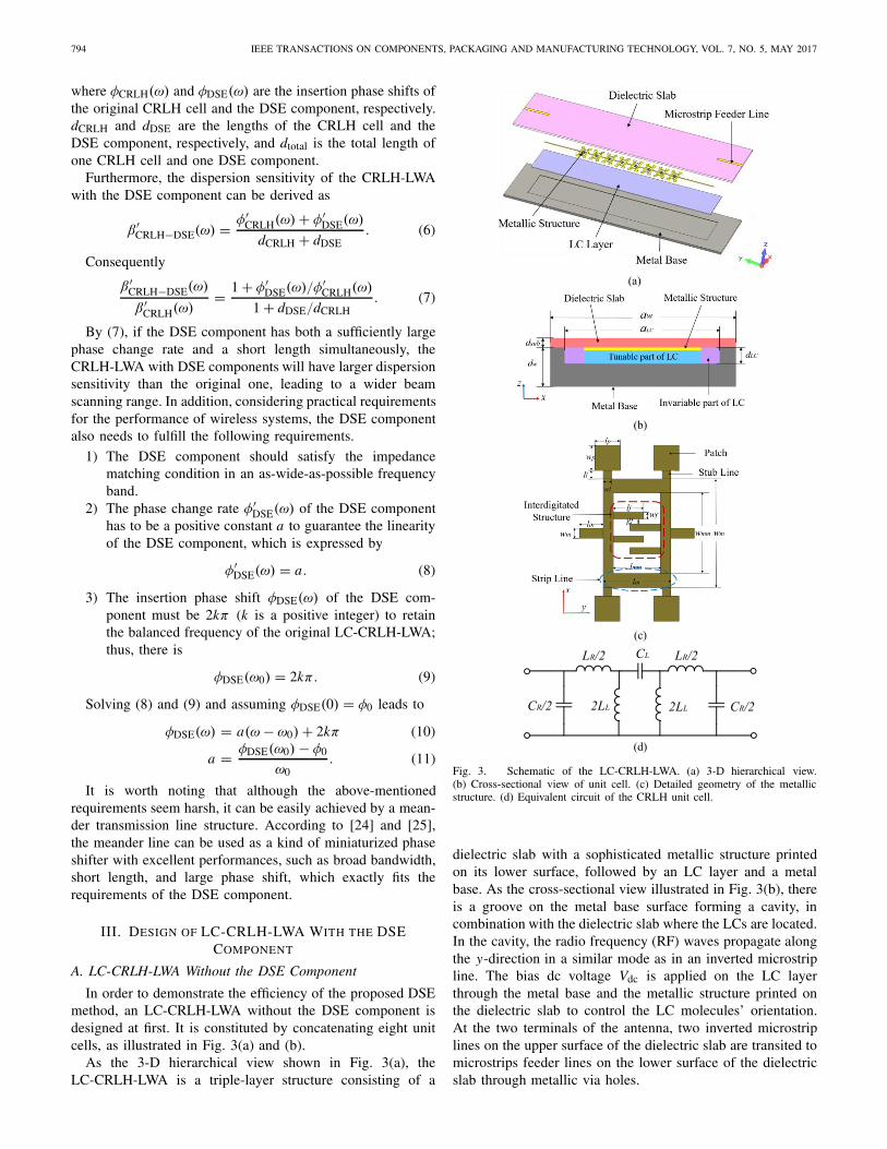
As the 3-D hierarchical view shown in Fig. 3(a), theLC-CRLH-LWA is a triple-layer structure consisting of a
Fig. 3. Schematic of the LC-CRLH-LWA. (a) 3-D hierarchical view.(b) Cross-sectional view of unit cell. (c) Detailed geometry of the metallicstructure. (d) Equivalent circuit of the CRLH unit cell.
dielectric slab with a sophisticated metallic structure printedon its lower surface, followed by an LC layer and a metalbase. As the cross-sectional view illustrated in Fig. 3(b), thereis a groove on the metal base surface forming a cavity, incombination with the dielectric slab where the LCs are located.In the cavity, the radio frequency (RF) waves propagate alongthe y-direction in a similar mode as in an inverted microstripline. The bias dc voltage Vdc is applied on the LC layerthrough the metal base and the metallic structure printed onthe dielectric slab to control the LC molecules’ orientation.At the two terminals of the antenna, two inverted microstriplines on the upper surface of the dielectric slab are transited tomicrostrips feeder lines on the lower surface of the dielectricslab through metallic via holes.
MA et al.: LIQUID CRYSTAL LEAKY-WAVE ANTENNAS WITH DISPERSION SENSITIVITY ENHANCEMENT 795
TABLE I
SIMULATION PARAMETERS OF THE LC-CRLH-LWA
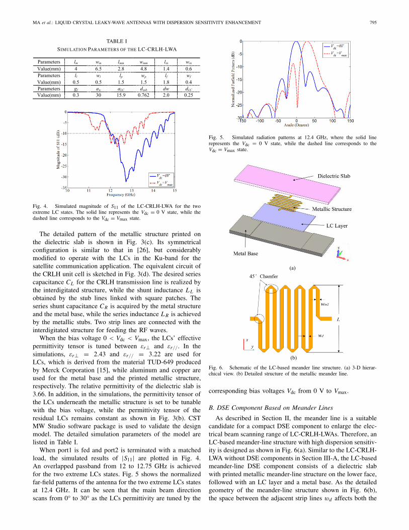
Fig. 4. Simulated magnitude of S11 of the LC-CRLH-LWA for the twoextreme LC states. The solid line represents the Vdc = 0 V state, while thedashed line corresponds to the Vdc = Vmax state.
The detailed pattern of the metallic structure printed onthe dielectric slab is shown in Fig. 3(c). Its symmetricalconfiguration is similar to that in [26], but considerablymodified to operate with the LCs in the Ku-band for thesatellite communication application. The equivalent circuit ofthe CRLH unit cell is sketched in Fig. 3(d). The desired seriescapacitance CL for the CRLH transmission line is realized bythe interdigitated structure, while the shunt inductance L L isobtained by the stub lines linked with square patches. Theseries shunt capacitance CR is acquired by the metal structureand the metal base, while the series inductance L R is achievedby the metallic stubs. Two strip lines are connected with theinterdigitated structure for feeding the RF waves.
When the bias voltage 0 < Vdc < Vmax, the LCs’ effectivepermittivity tensor is tuned between !r! and !r//. In thesimulations, !r! = 2.43 and !r// = 3.22 are used forLCs, which is derived from the material TUD-649 producedby Merck Corporation [15], while aluminum and copper areused for the metal base and the printed metallic structure,respectively. The relative permittivity of the dielectric slab is3.66. In addition, in the simulations, the permittivity tensor ofthe LCs underneath the metallic structure is set to be tunablewith the bias voltage, while the permittivity tensor of theresidual LCs remains constant as shown in Fig. 3(b). CSTMW Studio software package is used to validate the designmodel. The detailed simulation parameters of the model arelisted in Table I.
When port1 is fed and port2 is terminated with a matchedload, the simulated results of |S11| are plotted in Fig. 4.An overlapped passband from 12 to 12.75 GHz is achievedfor the two extreme LCs states. Fig. 5 shows the normalizedfar-field patterns of the antenna for the two extreme LCs statesat 12.4 GHz. It can be seen that the main beam directionscans from 0° to 30° as the LCs permittivity are tuned by the
Fig. 5. Simulated radiation patterns at 12.4 GHz, where the solid linerepresents the Vdc = 0 V state, while the dashed line corresponds to theVdc = Vmax state.
Fig. 6. Schematic of the LC-based meander line structure. (a) 3-D hierar-chical view. (b) Detailed structure of the metallic meander line.
corresponding bias voltages Vdc from 0 V to Vmax.
B. DSE Component Based on Meander Lines
As described in Section II, the meander line is a suitablecandidate for a compact DSE component to enlarge the elec-trical beam scanning range of LC-CRLH-LWAs. Therefore, anLC-based meander-line structure with high dispersion sensitiv-ity is designed as shown in Fig. 6(a). Similar to the LC-CRLH-LWA without DSE components in Section III-A, the LC-basedmeander-line DSE component consists of a dielectric slabwith printed metallic meander-line structure on the lower face,followed with an LC layer and a metal base. As the detailedgeometry of the meander-line structure shown in Fig. 6(b),the space between the adjacent strip lines wd affects both the
796 IEEE TRANSACTIONS ON COMPONENTS, PACKAGING AND MANUFACTURING TECHNOLOGY, VOL. 7, NO. 5, MAY 2017
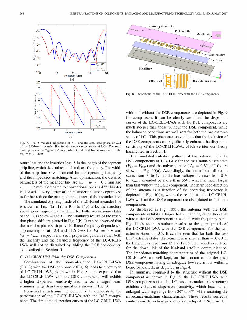
Fig. 7. (a) Simulated magnitude of S11 and (b) simulated phase of S21of the LC-based meander line for the two extreme states of LCs. The solidline represents the Vdc = 0 V state, while the dashed line corresponds to theVdc = Vmax state.
return loss and the insertion loss. L is the length of the segmentstrip line, which determines the bandpass frequency. The widthof the strip line win2 is crucial for the operating frequencyand the impedance matching. After optimization, the detailedparameters of the meander line are wd = win2 = 0.6 mm andL = 11.2 mm. Compared to conventional ones, a 45° chamferis devised at every corner of the meander line and is optimizedto further reduce the occupied circuit area of the meander line.
The simulated S11 magnitude of the LC-based meander lineis shown in Fig. 7(a). From 10.6 to 14.8 GHz, the structureshows good impedance matching for both two extreme statesof the LCs (below –20 dB). The simulated results of the inser-tion phase shift are plotted in Fig. 7(b). It can be observed thatthe insertion phase shift provides linear frequency dependence,approaching 0° at 12.4 and 11.6 GHz for Vdc = 0 V andVdc = Vmax, respectively. Such properties guarantee that boththe linearity and the balanced frequency of the LC-CRLH-LWA will not be disturbed by adding the DSE components,as described in Section II.
C. LC-CRLH-LWA With the DSE ComponentsCombination of the above-designed LC-CRLH-LWA
(Fig. 3) with the DSE component (Fig. 6) leads to a new typeof LC-CRLH-LWA, as shown in Fig. 8. It is expected thatthe LC-CRLH-LWA with the DSE components will exhibita higher dispersion sensitivity and, hence, a larger beamscanning range than the original one shown in Fig. 3.
Numerical simulations are conducted to demonstrate theperformance of the LC-CRLH-LWA with the DSE compo-nents. The simulated dispersion curves of the LC-CRLH-LWA
Fig. 8. Schematic of the LC-CRLH-LWA with the DSE components.
with and without the DSE components are depicted in Fig. 9for comparison. It can be clearly seen that the dispersioncurves of the LC-CRLH-LWA with the DSE components aremuch steeper than those without the DSE component, whilethe balanced conditions are well kept for both the two extremestates of LCs. This phenomenon validates that the inclusion ofthe DSE components can significantly enhance the dispersionsensitivity of the LC-CRLH-LWA, which verifies our theoryhighlighted in Section II.
The simulated radiation patterns of the antenna with theDSE components at 12.4 GHz for the maximum-biased state(Vdc = Vmax) and the unbiased state (Vdc = 0 V) of LCs areshown in Fig. 10(a). Accordingly, the main beam directionscans from 0° to 47° as the bias voltage increases from 0 Vto Vmax, extended by more than 56%, which is much largerthan that without the DSE component. The main lobe directionof the antenna as a function of the operating frequency isdepicted in Fig. 10(b), where the results for the LC-CRLH-LWA without the DSE component are also plotted to facilitatecomparison.
As displayed in Fig. 10(b), the antenna with the DSEcomponents exhibits a larger beam scanning range than thatwithout the DSE component in a quite wide frequency band.Fig. 11 shows the simulated results for the 11 magnitude ofthe LC-CRLH-LWA with the DSE components for the twoextreme states of LCs. It can be seen that for both the twoLCs’ extreme states, the return loss is smaller than "10 dB inthe frequency range from 12.1 to 12.75 GHz, which is suitablefor the down link of the Ku-band satellite communication.The impedance-matching characteristics of the original LC-CRLH-LWA are well kept, on the account of the designedDSE component having an adequate low return loss within aboard bandwidth, as depicted in Fig. 4.
In summary, compared to the structure without the DSEcomponent as shown in Fig. 6, the LC-CRLH-LWA withDSE components (i.e., the LC-based meander-line structure)exhibits enhanced dispersion sensitivity, which leads to anenlarged scanning range from 30° to 47° while retaining theimpedance-matching characteristics. These results perfectlyconfirm our theoretical predictions developed in Section II.

MA et al.: LIQUID CRYSTAL LEAKY-WAVE ANTENNAS WITH DISPERSION SENSITIVITY ENHANCEMENT 797
Fig. 9. Simulated dispersion curves of the LC-CRLH-LWA with and withoutthe DSE components for the two extreme states of LCs. The blue and red linesrepresent the Vdc = 0 V state, while the green and light blue lines correspondto the Vdc = Vmax state.
Fig. 10. (a) Simulated normalized far-field patterns. The solid line representsthe Vdc = 0 V state, while the dashed line corresponds to the Vdc = Vmaxstate LCs implying a beam scanning range of 47°. (b) Main lobe direction ofthe LC-CRLH-LWA with and without the DSE components as a function ofoperating frequency for the two extreme states of LCs. The blue and red linesrepresent the Vdc = 0 V state, while the green and light blue lines correspondto the Vdc = Vmax state.
IV. FABRICATION AND EXPERIMENTAL VERIFICATION
In order to demonstrate our proposed theoretical and numer-ical results, two prototype samples for the LC-CRLH- LWAswith and without the DSE components are fabricated andtested experimentally. The photographs of the samples areshown in Fig. 12(a) and (b).
A Rogers 4350B-type substrate and 0603-type aluminumalloy are used for the dielectric slab and the metal base,respectively. A groove is milled into the metal base surfaceforming a cavity together with the Rogers substrate. Computer
Fig. 11. Simulated magnitude of S11 of the LC-CRLH-LWA with the DSEcomponents for the two extreme states of LCs. The solid line represents theVdc = 0 V state, while the dashed line corresponds to the Vdc = Vmax state.
Fig. 12. Photographs of the fabricated LC-CRLH-LWA. (a) Inner structures.(b) Packaged sample.
Fig. 13. Schematic of measurement system for the LC-CRLH-LWA.
numerical control milling machine is used to obtain the groovewith 0.25 mm depth. A coating of polyvinyl alcohol is puton the surface of the groove and rubbed to realize the LCs’director alignment along the y-direction. Aligned screw holesare embedded around the substrate and the metal base forfixation with screws to package the LCs and ensure themechanical stability over time. Another two small holes inthe diagonal of the substrate are constituted to inject the LCsinto the cavity. Extra glue embraces the substrate and the metalbase for the final packaging.
Compared to the existing LC microwave devices, compo-nents realized by the fabrication methodology in this paperfeature low cost; compactness; ease of fabrication, design,and packaging; greater mechanical stability; and capability ofhandling high power.
798 IEEE TRANSACTIONS ON COMPONENTS, PACKAGING AND MANUFACTURING TECHNOLOGY, VOL. 7, NO. 5, MAY 2017
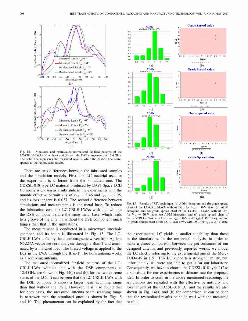
Fig. 14. Measured and resimulated normalized far-field patterns of theLC-CRLH-LWAs (a) without and (b) with the DSE components at 12.4 GHz.The solid line represents the measured results, while the dashed line corre-sponds to the resimulated results.
There are two differences between the fabricated samplesand the simulation models. First, the LC material used inthe experiment is different from the simulated one. TheCDZSL-018-type LC material produced by BAYI Space LCDCompany is chosen as a substitute in the experiments with thetunable effective permittivity of !r! = 2.46 and !r// = 2.95,and its loss tangent is 0.037. The second difference betweensimulations and measurements is the metal base. To reducethe fabrication cost, the LC-CRLH-LWAs with and withoutthe DSE component share the same metal base, which leadsto a groove of the antenna without the DSE component muchlonger than that in the simulations.
The measurement is conducted in a microwave anechoicchamber, and its setup is illustrated in Fig. 13. The LC-CRLH-LWA is fed by the electromagnetic waves from AgilentN5227A vector network analyzer through a Bias-T and termi-nated by a matched load. The biased voltage is applied to theLCs in the LWA through the Bias-T. The horn antenna worksas a receiving antenna.
The measured normalized far-field patterns of the LC-CRLH-LWA without and with the DSE components at12.4 GHz are shown in Fig. 14(a) and (b), for the two extremestates of the LCs. It can be seen that the LC-CRLH-LWA withthe DSE components shows a larger beam scanning rangethan that without the DSE. However, it is also found thatfor both cases, the measured antenna beam scanning rangeis narrower than the simulated ones as shown in Figs. 5and 10. This phenomenon can be explained by the fact that
Fig. 15. Results of FSV technique. (a) ADM histogram and (b) grade spreadchart of the LC-CRLH-LWA without DSE for Vdc = 0-V state. (c) ADMhistogram and (d) grade spread chart of the LC-CRLH-LWA without DSEfor Vdc = 20-V state. (e) ADM histogram and (f) grade spread chart ofthe LC-CRLH-LWA with DSE for Vdc = 0-V state. (g) ADM histogram and(h) grade spread chart of the LC-CRLH-LWA with DSE for Vdc = 20-V state.
the experimental LC yields a smaller tunability than thosein the simulations. In the numerical analysis, in order tomake a direct comparison between the performances of ourdesigned antenna and previously reported works, we modelthe LC strictly referring to the experimental one of the MerckTUD-649 in [15]. This LC supports a strong tunability, but,unfortunately, we were not able to get it for our laboratory.Consequently, we have to choose the CDZSL-018-type LC asa substitute for our experiments to demonstrate the proposedidea. In order to confirm the above-mentioned reasoning, thesimulations are repeated with the effective permittivity andloss tangent of the CDZSL-018 LC, and the results are alsoshown in Fig. 14(a) and (b) for comparison. It can be seenthat the resimulated results coincide well with the measuredresults.
MA et al.: LIQUID CRYSTAL LEAKY-WAVE ANTENNAS WITH DISPERSION SENSITIVITY ENHANCEMENT 799
Furthermore, the feature selective validation (FSV)technique [27]–[29] is applied to provide a quantifiedand comprehensible evaluation on the measured andsimulated results. In the case of LC-CRLH-LWAs, theamplitude difference measure value is expected to assessthe similarity of the measured and simulated far-fieldpatterns. The statistical amplitude difference measure(ADM) histograms by the FSV approach are obtained inFig. 15(a), (c), (e), and (g) corresponding to the antennaswithout or with the DSE components for Vdc = 0 V orVdc = Vmax state. In all the cases, a strong similarity isrevealed in the ADM histograms between simulations andmeasurements (Excellent + Very Good + Good + Fair >80%). Moreover, the corresponding grade spread values aredisplayed in Fig. 15(b), (d), (f), and (h) for comprehensivequantification and visual indication [30], [31]. In all thecases, the grade and spread values of the ADM, the featuredifference measure (FDM), and the global difference measureare between 4–5 and 3–4, respectively, thus indicating a poorto good agreement of the measured (GDM) and simulatedfar-field patterns. This result may well be accepted as goodagreement between two plots, despite having some differenceswith respect to machining errors, instrumental errors, andnoise.
V. CONCLUSION
A general design, fabrication, and packaging method ofelectrically tunable LC-CRLH-LWAs with enlarged beamscanning range is put forward. The LCs are packaged byPCB processing technology combined with the metal precisionmachining process, which makes the design of LC microwavecomponents no longer limited by the microelectronics process-ing technology. Theoretical analyses demonstrate that theslope of dispersion curves of LC-CRLH-LWA is a criticalfactor to the beam scanning range. Afterward, a specificDSE component with high dispersion sensitivity and goodimpedance matching property is designed and added to an LC-CRLH-LWA to expand the electronic beam scanning range.Simulated results exhibit that the DSE method improves thebeam scanning range from 30° to 47° for operating fre-quencies within the spectral band from 12.1 to 12.75 GHz,which is suitable for the down link of the Ku-band satellitecommunication. Measurements are conducted to confirm thetheoretical and numerical results, and the FSV technique isutilized to assess the similarity between the experimentaland simulated results. Furthermore, this fabrication technologymakes LC components with low cost, mechanical stability,ease of manufacture, and flexible design. In conclusion, ournovel beam scanning method and fabrication methodology ofLC components are fully functional and highly effective.
ACKNOWLEDGMENT
The authors would like to thank the reviewers and editorsfor their constructive comments and suggestions, which havebeen valuable to improve this paper.
REFERENCES
[1] J. L. Gomez-Tornero, F. D. Quesada-Pereira, and A. Alvarez-Melcon,“Analysis and design of periodic leaky-wave antennas for the millimeterwaveband in hybrid waveguide-planar technology,” IEEE Trans. Anten-nas Propag., vol. 53, no. 9, pp. 2834–2842, Sep. 2005.
[2] J. Liu, D. R. Jackson, Y. Li, C. Zhang, and Y. Long, “Investigationsof SIW leaky-wave antenna for endfire-radiation with narrow beam andsidelobe suppression,” IEEE Trans. Antennas Propag., vol. 62, no. 9,pp. 4489–4497, Sep. 2014.
[3] A. J. Martinez-Ros, J. L. Gomez-Tornero, and G. Goussetis, “Planarleaky-wave antenna with flexible control of the complex propagationconstant,” IEEE Trans. Antennas Propag., vol. 60, no. 3, pp. 1625–1630,Mar. 2012.
[4] A. Mehdipour and G. V. Eleftheriades, “Leaky-wave antennas usingnegative-refractive-index transmission-line metamaterial supercells,”IEEE Trans. Antennas Propag., vol. 62, no. 8, pp. 3929–3942,Aug. 2014.
[5] W. Cao, Z. N. Chen, W. Hong, B. Zhang, and A. Liu, “A beamscanning leaky-wave slot antenna with enhanced scanning angle rangeand flat gain characteristic using composite phase-shifting transmissionline,” IEEE Trans. Antennas Propag., vol. 62, no. 11, pp. 5871–5875,Nov. 2014.
[6] L. Cui, W. Wu, and D.-F. Fang, “Printed frequency beam-scanningantenna with flat gain and low sidelobe levels,” IEEE Antennas WirelessPropag. Lett., vol. 12, pp. 292–295, 2013.
[7] N. Apaydin, K. Sertel, and J. L. Volakis, “Nonreciprocal and magnet-ically scanned leaky-wave antenna using coupled CRLH lines,” IEEETrans. Antennas Propag., vol. 62, no. 6, pp. 2954–2961, Jun. 2014.
[8] T. Kodera, D. L. Sounas, and C. Caloz, “Nonreciprocal magnetlessCRLH leaky-wave antenna based on a ring metamaterial structure,”IEEE Antennas Wireless Propag. Lett., vol. 10, pp. 1551–1554, 2011.
[9] H. Paaso, A. Mammela, D. Patron, and K. R. Dandekar, “DoA esti-mation through modified unitary MUSIC algorithm for CRLH leaky-wave antennas,” in Proc. Int. Symp. IEEE Pers. Indoor Mobile RadioCommun. (PIMRC), London, U.K., Sep. 2013, pp. 311–315.
[10] H. V. Nguyen, S. Abielmona, and C. Caloz, “End-switched CRLHleaky-wave antenna with enhanced electronic full-space beam steeringperformance,” in Proc. 5th Eur. Conf. Antennas Propag., Rome, Italy,2011, pp. 3501–3503.
[11] S. Bulja, D. Mirshekar-Syahkal, R. James, S. E. Day, andF. A. Fernandez, “Measurement of dielectric properties of nematic liquidcrystals at millimeter wavelength,” IEEE Trans. Microw. Theory Techn.,vol. 58, no. 12, pp. 3493–3501, Dec. 2010.
[12] I. C. Khoo, D. H. Werner, X. Liang, A. Diaz, and B. Weiner,“Nanosphere dispersed liquid crystals for tunable negative–zero–positiveindex of refraction in the optical and terahertz regimes,” Opt. Lett.,vol. 31, no. 17, pp. 2592–2594, 2006.
[13] D. H. Werner, D.-H. Kwon, I.-C. Khoo, A. V. Kildishev, andV. M. Shalaev, “Liquid crystal clad near-infrared metamaterials withtunable negative-zero-positive refractive indices,” Opt. Express, vol. 15,no. 6, pp. 3342–3347, 2007.
[14] F. Zhang, L. Kang, Q. Zhao, J. Zhou, X. Zhao, and D. Lippens, “Mag-netically tunable left handed metamaterials by liquid crystal orientation,”Opt. Express, vol. 17, no. 6, pp. 4360–4366, 2009.
[15] M. Roig, M. Maasch, C. Damm, and R. Jakoby, “Dynamic beamsteering properties of an electrically tuned liquid crystal based CRLHleaky wave antenna,” in Proc. Int. Conf. Adv. Electromagn. Mater.Microw. Opt. (METAMATERIALS), Kongens Lyngby, Denmark, 2014,pp. 253–255.
[16] M. Roig, M. Maasch, C. Damm, and R. Jakoby, “Liquid crystal-basedtunable CRLH-transmission line for leaky wave antenna applications atKa-Band,” Int. J. Microw. Wireless Tech., vol. 6, pp. 325–330, Mar. 2014.
[17] M. Roig, M. Maasch, C. Damm, and R. Jakoby, “Electrically tunableliquid crystal based composite right/left-handed leaky-wave antenna at26.7 GHz,” in Proc. 44th Eur. Microw. Conf. (EuMC), Rome, Italy, 2014,pp. 331–334.
[18] C. Damm, M. Maasch, R. Gonzalo, and R. Jakoby, “Tunable com-posite right/left-handed leaky wave antenna based on a rectangularwaveguide using liquid crystals,” in IEEE MTT-S Int. Microw. Symp.Dig., May 2010, pp. 13–16.
[19] H. Lee, J. H. Choi, C. T. M. Wu, and T. Itoh, “A compact singleradiator CRLH-inspired circularly polarized leaky-wave antenna basedon substrate-integrated waveguide,” IEEE Trans. Antennas Propag.,vol. 63, no. 10, pp. 4566–4572, Oct. 2015.
800 IEEE TRANSACTIONS ON COMPONENTS, PACKAGING AND MANUFACTURING TECHNOLOGY, VOL. 7, NO. 5, MAY 2017
[20] F. Bigelli et al., “Design and fabrication of a dielectricless substrate-integrated waveguide,” IEEE Trans. Compon., Packag., Manuf. Technol.,vol. 6, no. 2, pp. 256–261, Feb. 2016.
[21] Q. Yang, X. Zhao, and Y. Zhang, “Composite right/left-handed ridgesubstrate integrated waveguide slot array antennas,” IEEE Trans. Anten-nas Propag., vol. 62, no. 4, pp. 2311–2316, Apr. 2014.
[22] C. Jin and A. Alphones, “Leaky-wave radiation behavior from a doubleperiodic composite right/left-handed substrate integrated waveguide,”IEEE Trans. Antennas Propag., vol. 60, no. 4, pp. 1727–1735, Apr. 2012.
[23] Q. Yang, Y. Zhang, and X. Zhang, “X-band composite right/left-handedleaky wave antenna with large beam scanning-range/bandwidth ratio,”Electron. Lett., vol. 48, no. 13, pp. 746–747, Jun. 2012.
[24] S. Bulja and D. Mirshekar-Syahkal, “Meander line millimetre-waveliquid crystal based phase shifter,” Electron. Lett., vol. 46, no. 11,pp. 769–771, May 2010.
[25] J. Wu et al., “Compact, low-loss, wideband, and high-power han-dling phase shifters with piezoelectric transducer-controlled metallicperturber,” IEEE Trans. Microw. Theory Techn., vol. 60, no. 6,pp. 1587–1594, Jun. 2012.
[26] C.-Y. Liu, Q.-X. Chu, and J.-Q. Huang, “A planar D-CRLH transmissionline structure and its application to leaky-wave antenna,” in Proc. Int.Symp. Antennas Propag. EM Theory (ISAPE), Guangzhou, China, 2010,pp. 345–348.
[27] Standard for Validation of Computational Electromagnetics ComputerModeling and Simulation—Part 1, 2, IEEE Standard P1597, 2008.
[28] A. P. Duffy, A. J. M. Martin, A. Orlandi, G. Antonini, T. M. Benson,and M. S. Woolfson, “Feature selective validation (FSV) for validationof computational electromagnetics (CEM). Part I—The FSV method,”IEEE Trans. Electromagn. Compat., vol. 48, no. 3, pp. 449–459,Aug. 2006.
[29] A. Orlandi, A. P. Duffy, B. Archambeault, G. Antonini, D. E. Coleby,and S. Connor, “Feature selective validation (FSV) for validation ofcomputational electromagnetics (CEM). Part II—Assessment of FSVperformance,” IEEE Trans. Electromagn. Compat., vol. 48, no. 3,pp. 460–467, Aug. 2006.
[30] A. Orlandi, G. Antonini, C. Ritota, and A. P. Duffy, “Enhancing featureselective validation (FSV) interpretation of EMC/SI results with grade-spread,” in Proc. IEEE Int. Symp. (EMC), Aug. 2006, pp. 362–367.
[31] B. Archambeault, A. P. Duffy, and A. Orlandi, “Using the featureselective validation technique to compare data sets,” in Proc. IEEE Int.Symp. (EMC), Aug. 2009, pp. 248–253.
Shuang Ma received the bachelor’s and master’sdegrees in microwave engineering from the HarbinInstitute of Technology, Harbin, China, in 2012 and2014, respectively, where she is currently pursuingthe Ph.D. degree with the Department of MicrowaveEngineering.
Her current research interests include beam-steering antenna, active frequency selective surface,and tunable microwave device and antenna.
Ms. Ma was an award recipient from the IEEE 5thGlobal Symposium on Millimeter Waves, Harbin,
China, in 2012, the International Journal of Security and its Applicationsin 2013, and the 17th Biennial Conference on Electromagnetic Field Compu-tation, Miami, FL, USA, in 2016.
Guo-Hui Yang (S’07–M’09) received the B.S.degree in telecommunication, the M.S. degree ininstrument science and technology, and the Ph.D.degree in electromagnetics from the Harbin Instituteof Technology, Harbin, China, in 2003, 2006, and2009, respectively.
Since 2009, he has been with the Department ofMicrowave Engineering, Harbin Institute of Technol-ogy, where he is currently an Associate Professor.His current research interests include RF micro-electromechanical systems device, tunable antenna,
frequency selective surface, electromagnetic compatibility, and finite-difference time domain.
Daniel Erni (S’88–M’93) received the Diplomadegree in electrical engineering from the Universityof Applied Sciences Rapperswil, Rapperswil-Jona,Switzerland, in 1986, and the Diploma degree inelectrical engineering and the Ph.D. degree fromETH Zürich, Zürich, Switzerland, in 1990 and 1996,respectively.
Since 1990, he has been with the Laboratory ofElectromagnetic Fields and Microwave Electronics,ETH Zürich, where he was the Founder from 1995 to2006 and the Head of the Communication Photonics
Group. Since 2006, he has been a Full Professor of general and theoreticalelectrical engineering with the University of Duisburg–Essen, Duisburg,Germany. On the system level, he has pioneered the introduction of numericalstructural optimization into dense integrated optics device design. His currentresearch interests include advanced data transmission schemes (i.e., O-MIMO)in board-level optical interconnects, optical on-chip interconnects, ultradenseintegrated optics, nanophotonics, plasmonics, quantum optics, and optical andelectromagnetic metamaterials, with special focus on biomedical engineering,namely, for advanced RF excitation schemes in magnetic resonance imaging.
Dr. Erni is a Fellow of the Electromagnetics Academy. He is a member ofthe Center for Nanointegration Duisburg–Essen, the Applied ComputationalElectromagnetics Society, the Swiss Physical Society, the German PhysicalSociety, and the Optical Society of America. He is an Associated Member ofthe Swiss Electromagnetics Research Center. He is a member of the EditorialBoard of the Journal of Computational and Theoretical Nanoscience.
Fan-Yi Meng (S’07–M’09–SM’15) received theB.S., M.S., and Ph.D. degrees in electromagneticsfrom the Harbin Institute of Technology (HIT),Harbin, China, in 2002, 2004, and 2007, respec-tively.
Since 2007, he has been with the Departmentof Microwave Engineering, HIT, where he is cur-rently a Professor. He has coauthored four books,40 international refereed journal papers, over 20regional refereed journal papers, and 20 internationalconference papers. His current research interests
include antennas, electromagnetic and optical metamaterials, plasmonics, andelectromagnetic compatibility.
Dr. Meng was a recipient of several awards, including the 2013 Top YoungInnovative Talents of Harbin Institute of Technology, the 2013 CST UniversityPublication Award, the 2010 Award of Science and Technology from theHeilongjiang Province Government of China, the 2010 Microsoft Cup IEEEChina Student Paper Contest Award, two Best Paper Awards from the NationalConference on Microwave and Millimeter Wave, China, in 2009 and 2007,the 2008 University Excellent Teacher Award of the National University ofSingapore, the 2007 Excellent Graduate Award of Heilongjiang Province ofChina, and the Outstanding Doctor Degree Dissertation Award of the HarbinInstitute of Technology.
Lei Zhu received the Ph.D. degree in electromagnet-ics from the Harbin Institute of Technology, Harbin,China, in 2014.
Since 2004, she has been with the Communica-tion and Electronics Engineering Institute, QiqiharUniversity, Qiqihar, China, where she is currentlyan Associate Professor. She has coauthored twobooks and has authored or coauthored over 30 inter-national and regional refereed journal papers. Hercurrent research interests include electromagneticand optical metamaterials, graphene, all-dielectric
metamaterial, antenna design, and microwave devices.
MA et al.: LIQUID CRYSTAL LEAKY-WAVE ANTENNAS WITH DISPERSION SENSITIVITY ENHANCEMENT 801
Qun Wu (M’93–SM’05) received the B.Sc. degreein radio engineering, the M.Eng. degree in elec-tromagnetic fields and microwaves, and the Ph.D.degree in communication and information sys-tems from the Harbin Institute of Technology(HIT), Harbin, China, in 1977, 1988, and 1999,respectively.
He was a Visiting Professor with Seoul NationalUniversity, Seoul, South Korea, from 1998 to1999, the Pohang University of Science andTechnology, Pohang, South Korea, from 1999 to
2000, and the National University of Singapore, Singapore, from 2003to 2010. Since 1990, he has been with the School of Electronicsand Information Engineering, HIT, where he is currently a Professorand the Head of the Department of Microwave Engineering. He isalso a Director of the Center for Microwaves and Electro Magnetic Compati-bility. He has authored or coauthored several books and over 100 internationaland regional refereed journal papers. His current research interests includeelectromagnetic compatibility, metamaterials, and antennas.
Dr. Wu received the Science and Technology Award from the HeilongjiangProvincial Government in 2010. He is a member of the Microwave Society ofthe Chinese Institute of Electronics. He is a Technical Reviewer for severalinternational journals. He is also a Vice-Chair of the IEEE Harbin Section,and a Chair of the IEEE Harbin EMC/AP/MTT Joint Society Chapter. Hewas a Chair or a Member with the TPC of international conferences manytimes. He was also invited to give a keynote report or invited papers in someinternational conferences many times.
Jia-Hui Fu (M’07–SM’16) received the B.S. degreein electronics and communication engineering, theM.S. degree in electromagnetic fields and microwavetechnology, and the Ph.D. degree in communi-cation and information systems engineering fromthe Harbin Institute of Technology (HIT), Harbin,China, in 1998, 2000, and 2005, respectively.
Since 2007, he has been with the Department ofMicrowave Engineering, HIT, where he is currentlya Professor. His current research interests includemicrowave and millimeter-wave circuits, left-handed
medium, microelectromechanical systems, and electromagnetic compatibility.