Embed Size (px)
Citation preview

1

2
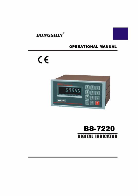
Thank you very much for your purchasing BONGSHIN Digital Weighing
Indicator of BS-7220.
This Instruction Manual will lead you to use BS-7220 with top reliability,
High speed, high accuracy.
BS-7220 is Digital Weighing Indicator amplifying the analog output from a
load Cell, converting the analog signal to digital data and then displaying
this data
As a weight reading and is designed for flawless performance in your
demanding
Application of input-weighing, output-weighing, accumulating-weighing,
2step control.
Also, an additional option will make Modern Industry demand equipment
that both versatile
And availed to easily connect to other devices
REMARK
- Specification subject to change for improvement without prior notice.
- If changing, the Version No can be increased, but keeps a former
version
As far as possible

3
Please keep the following using conditions certainly
EARTH
To avoid an electric error such as a noises in your production line
It should be earthed before installation certainly.
Specially it will be safety to divide the power of Indicator into a load cell.
SAFTY CONDITIONS
Don’t use it closed to a explosive gas and an inflammable dust
environments
POWER
Use the power under 110/220V 50/60HZ ±10% and divide it into the
power line
TEMPERTURE CONDITIONS
Operating Temperature : -10o C ∼ +40o C ( +14o to 104o F )
Custody Temperature : -40o C ∼ +80o C ( -40o to 176o F )
INSTALLATION LOAD CELL
- Available to use the same load cell of 8pcs ( 350Ω standard )
- A ground should be installed horizontal
- Installing over 2pcs of load cell, please connect each line in parallel
and Insert a variable resistor under 50Ω in EX + line and minimize a
output
Accuracy of load cell.
It may occur a weight error by each accuracy of load cell.
- It may occur a weight error in case of a temperature variation of
load cell
- Please weld(elect spark) at the place installed with load cell and
equipments,
Divide the power into a connector of load cell in inevitable case
- Please connect the below construction of load cell with the above ones using
The earth to the weighing part weighing a material occurring a electro
sparks.
4
- 24bit sigma-delta A/D converter for high accuracy Easy
- Full digital calibration
- Simulative(mV/V memory) or live load calibration
- Peak hold and remote auto zero, tare
- High brightness VFD display
- A compact Appearance by DIN regulations ( DIN 193 x 96 Panel system )
- Easy to preset, change, confirm the weight value by the numeral key.
- Weight Memory function even in electro spark case.
- Watch-Dog timer guards for self-diagnostics.
- Set up to 1/10,000 display resolution
- Various specification of weight conversion speed.
(Digital Filter Function)
- Various option and addition for customer’s satisfaction such as serial
communication, RS-422, Analog output, Current LOOP, Printer, BCD
parallel output and so on.

5
DC 10V ±5%, 300
up to 8 x 350ohm load cells
0.3 μV/D
Within 0.01% F.S.
-1 ~ +34
Max. 34 Min. 5
Zero drift : ±0.2 μV/ RTI max.
Span drift : 20ppm/ max.
±0.3 μV p.p or less
10 (Min.)
Sigma-Delta system
Approximately 200,000 counts
1/20,000 (Max.)
50 times/sec
1/20,000
7 Segment VFD,
6-Digits, 13mm(Height)
“-”minus signal
Stable, Zero, Relay Point(L1~L2),
TARE
x1, x2, x5, x10, x20, x50, x100, x200
0, 0.0, 0.00, 0.000, 0.0000

6
AC 110/220V ±10%, 50/60Hz
20 VA
10 year
-10~+40 (+14 ~ +104 )
85% Rh Max.
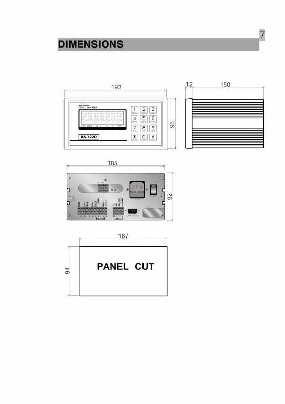
193(W) x 162(D) x 96(H)
2.5 kg
Serial Interface : RS-232C
– Serial Interface : RS-422
– Serial Interface : Current Loop
– Analog Output : 0~10V
– Analog Output : 4~20mA
– Parallel Interface : BCD OUTPUT
7

8
: ON when the weight is stable.
: ON when the current weight is 0 kg.
: : It will lamp when 1step(90%) control works
: : It will lamp when 2step(100%) control works
: Not Used (BS-7300 application)
: ON when the tare weight is stored.
This Lamp will be switched to Net mode
9
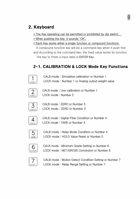
* The Key operating can be permitted or prohibited by dip switch.
* When pushing the key, it sounds "OK".
* Each Key works either a single function or compound functions.
A compound function key will be a command key when it push first
and According to the command key, the fixed value works its function,
The key to finish a input data is ENTER Key.
CALB mode : Simulative calibration or Number 1
LOCK mode : Number 1 or Analog output weight value
CALB mode : Live calibration or Number 1
LOCK mode : Number 2
CALB mode : ZERO or Number 3
LOCK mode : ZERO or Number 3
CALB mode : Digital Filter Condition or Number 4
LOCK mode : TARE or Number 4
CALB mode : Relay Mode Condition or Number 5
LOCK mode : HOLD Value Reset or Number 5
CALB mode : Minimum Grade Setting or Number 6
LOCK mode : NET/GROSS Conversion or Number 6
CALB mode : Motion Detect Condition Setting or Number 7
LOCK mode : Relay Range Setting or Number 7
10
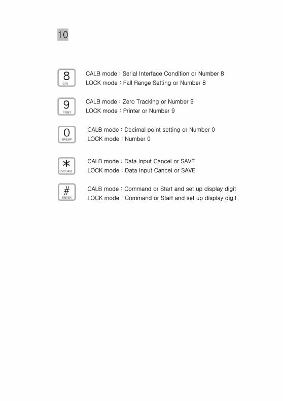
CALB mode : Serial Interface Condition or Number 8
LOCK mode : Fall Range Setting or Number 8
CALB mode : Zero Tracking or Number 9
LOCK mode : Printer or Number 9
CALB mode : Decimal point setting or Number 0
LOCK mode : Number 0
CALB mode : Data Input Cancel or SAVE
LOCK mode : Data Input Cancel or SAVE
CALB mode : Command or Start and set up display digit
LOCK mode : Command or Start and set up display digit
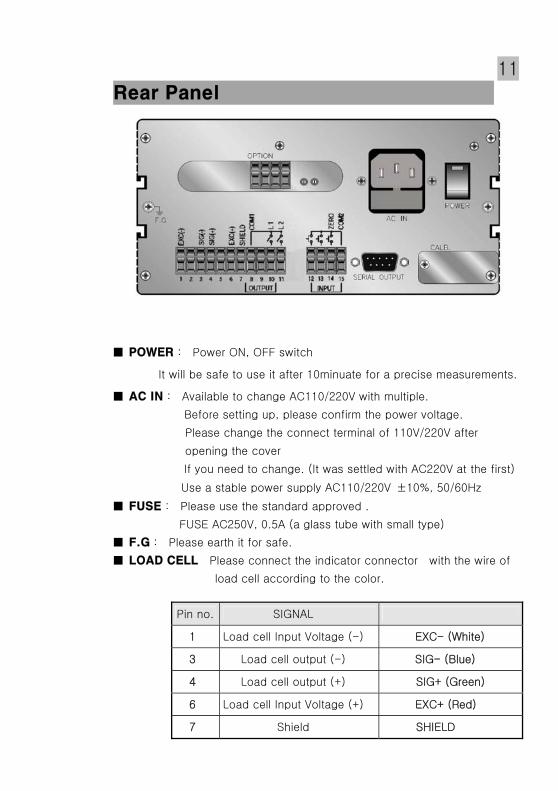
11
: Power ON, OFF switch
It will be safe to use it after 10minuate for a precise measurements.
: Available to change AC110/220V with multiple.
Before setting up, please confirm the power voltage.
Please change the connect terminal of 110V/220V after
opening the cover
If you need to change. (It was settled with AC220V at the first)
Use a stable power supply AC110/220V ±10%, 50/60Hz
: Please use the standard approved .
FUSE AC250V, 0.5A (a glass tube with small type)
: Please earth it for safe.
Please connect the indicator connector with the wire of
load cell according to the color.
Pin no. SIGNAL
1 Load cell Input Voltage (-) EXC- (White)
3 Load cell output (-) SIG- (Blue)
4 Load cell output (+) SIG+ (Green)
6 Load cell Input Voltage (+) EXC+ (Red)
7 Shield SHIELD
12
The wire color of load cell according to a manufactures.
1
EXC-
3
SIG-
4
SIG+
6
EXC+
7
SHIELD
CAS, TMI, AND WHITE BLUE GREEN RED SHIELD
BLH BLACK RED WHITE GREEN YELLOW
INTERFACE BLACK WHITE GREEN RED SHIELD
KYOWA BLACK WHITE GREEN RED SHIELD
P.T. BLACK WHITE GREEN RED SHIELD
SHOWA BLUE BLACK WHITE RED SHIELD
SHINKOH BLACK WHITE GREEN RED SHIELD
TML BLACK GREEN WHITE RED SHIELD
TFAC BLUE BLACK WHITE RED YELLOW
HUNTLEIGH BLACK WHITE RED GREEN SHIELD
※ Because wire color may be different according to a manufacture and
load cell models. Please refer for the data sheet of load cell.
SIG- (Blue)
SHIELD
SIG+ (Green)
EXC+
EXC-
SIG+ SIG-
1
2
4
3
5
EXC+ (Red)
EXC- (White)
6
7

13
: COM1, L 1, L 2,
Connect between COM terminal and OUTPUT terminal
With the earth of no electric power.
Please use the output data For a signal only, don’t use it for working.
Max earth capacity : AC250V / 0.5A
: COM2, I-HOLD, P-HOLD, ZERO
This key is to control a equipment from the outside .
Please connect between COM terminal and each input terminal .
Because the power of input terminal was connected with 12V voltage
From the inside.
* An electric current is about 10mA.
* Please make the minimum time to input a data with over 50mSEC.

14
: CALIBRATION & LOCK mode
SW 1 ON (Down) : Shift to lock mode. (weighing mode)
SW 1 OFF (Up) : Shift to calibration mode.
: Not used
Serial Interface : RS-232C
– Serial Interface : RS-422
– Serial Interface : Current Loop
– Analog Output : 0~10V
– Analog Output : 4~20mA
– Parallel Interface : BCD OUTPUT

15
GENEANL RULES
- Avoid sudden Collision, vibration, temperature, water, wind
- Use a stable power supply 110V/220V ± 10% 50/60Hz
Set up voltage 220V
(Adjust the power voltage because the choice terminal of power is inside.)
- Connect and power off the switch when connecting the external
equipments.
- Ensure to earth Indicator to equipments
- Ensure to calibrate and set up it for operating.
* PARTS
- POWER CODE : 1EA
- FUSE : 1EA (PIPE TYPE 250V 0.5A SMALL TYPE)
- OPERATING MANUAL : 1EA
- A Stable Connector for Option installation.
INLET
FUSE : AC250V, 500mA
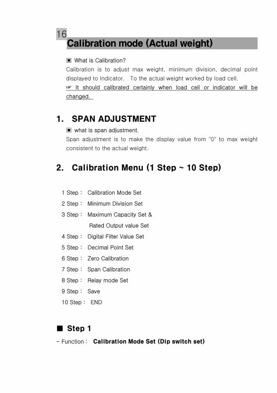
16
What is Calibration?
Calibration is to adjust max weight, minimum division, decimal point
displayed to Indicator. To the actual weight worked by load cell.
It should calibrated certainly when load cell or indicator will be
changed.
what is span adjustment.
Span adjustment is to make the display value from "0" to max weight
consistent to the actual weight.
1 Step : Calibration Mode Set
2 Step : Minimum Division Set
3 Step : Maximum Capacity Set &
Rated Output value Set
4 Step : Digital Filter Value Set
5 Step : Decimal Point Set
6 Step : Zero Calibration
7 Step : Span Calibration
8 Step : Relay mode Set
9 Step : Save
10 Step : END
- Function :
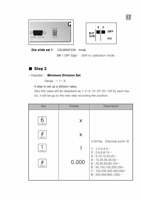
17
: CALIBRATION mode
SW 1 OFF (Up) : Shift to calibration mode.
- Function :
Range → 1~ 8
A step to set up a division value.
Also this value will be displayed as 1-2-5-10-20-50-100 by each key.
So, it will be go to the next step recording the position.
Key Display Description
x
x
1
0.000
0.001Kg (Decimal point: 3)
1 : 1,2,3,4,5…
2 : 2,4,6,8,10…
3 : 5,10,15,20,25…
4 : 10,20,30,40,50…
5 : 20,40,60,80,100…
6 : 50,100,150,200,250…
7 : 100,200,300,400,500…
8 : 200,400,800,1000…

18
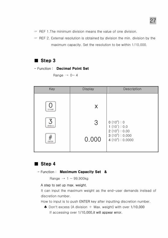
REF 1.The minimum division means the value of one division.
REF 2. External resolution is obtained by division the min. division by the
maximum capacity. Set the resolution to be within 1/10,000.
- Function :
Range → 1 ~ 99,900kg
A step to set up max. weight.
It can input the maximum weight as the end-user demands instead of
discretion number.
How to input is to push ENTER key after inputting discretion number.
♣ Don’t excess (A division ÷ Max. weight) with over 1/10,000
If accessing over 1/10,000,it will appear error.
- Function :
Range → 1.0000 mV/V ~ 3.0000 mV/V
The display discretion number "r2.0000" (rated output 5figure)
Please input the value of standard weight for span adjustment by
numeric key.
How to input is to push ENTER key after inputting discretion number.

19 Key Display Description
Full Capacity Value Input
(xxxxx)
Load Cell Rated Output
Value Input (xxxxx)
xx.xxx
xx.xxx
xx.xxx
x.xxxx
x.xxxx
0.000
mV/V
REF 1. The maximum capacity means the maximum weight that scale
can measure.
REF 2. A data sheet is attached to a strain-gage sensor at the time of
purchase.
The data sheet provides data including:
capacity load(in kg, t, etc.)
rated output. Voltage(in mV/V)
non-linearity, Hysteresis, input resistance, output resistance and
zero balance.
Enter the capacity and the rated output value required for
equivalent input calibration into the BS-7220.
- Function :
Range → 1~ 9
Adjust the set value according to the condition how many times
converted digital value read and display.
How to input is to push ENTER key after inputting discretion

20
Key Display Description
x
x
3
0.000
1 : Less vibration
~
9 : Much vibration
- Function :
Range → 0~ 4
Key Display Description
x
3
0.000
0 (100) : 0
1 (101) : 0.0
2 (102) : 0.00
3 (103) : 0.000
4 (104) : 0.0000

21
- Function :
A step to check the zero conditions of Indicator.
After appearing "ZEro", please push ENTER key.
Please do it as the zero adjustment instruction.
Key Display Description
0
ZEro
0.000
Unload the tray and press
“ENTER” key Under zero
calibration
Zero calibration is
completed.
REF 1. If the “ZERO” key is pressed, only zero calibration is completed
and program moves SAVE & EXIT mode.
please push ESC key.
- Function :
Range → 1~ 99,900kg
The display discretion number "10.000" (span 5figure)
Please input the value of standard weight for span adjustment by
numeric key.
How to input is to push ENTER key after inputting discretion number.
Please put the span standard weight on the platform.(the weight
is 10000kg at here)
Press ENTER key after stable of platform.
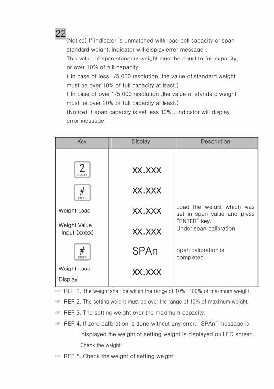
22 (Notice) If indicator is unmatched with load cell capacity or span
standard weight, indicator will display error message .
This value of span standard weight must be equal to full capacity,
or over 10% of full capacity.
( In case of less 1/5,000 resolution ,the value of standard weight
must be over 10% of full capacity at least.)
( In case of over 1/5,000 resolution ,the value of standard weight
must be over 20% of full capacity at least.)
(Notice) If span capacity is set less 10% , indicator will display
error message.
Key Display Description
Weight Load
Weight Value
Input (xxxxx)
Weight Load
Display
xx.xxx
xx.xxx
xx.xxx
xx.xxx
SPAn
xx.xxx
Load the weight which was
set in span value and press
“ENTER” key.
Under span calibration
Span calibration is
completed.
REF 1. The weight shall be within the range of 10%~100% of maximum weight.
REF 2. The setting weight must be over the range of 10% of maximum weight.
REF 3. The setting weight over the maximum capacity.
REF 4. If zero calibration is done without any error, “SPAn” message is
displayed the weight of setting weight is displayed on LED screen.
Check the weight.
REF 5. Check the weight of setting weight.

23
Relay OFF
Relay ON
ON
ON
Relay Out
L1
100 Weight
Display
OFF
OFF
200
ON
OFF
---설 정----
L1 ------ 100
L2 ------ 200
L2
- Function :
Range → 0 or 1
Two kinds of way of input set point are available.
This key is used for sum of unit weight and relay mode or numeric key "5" .
Press the "5" key, appear the "x" on the unit display part.
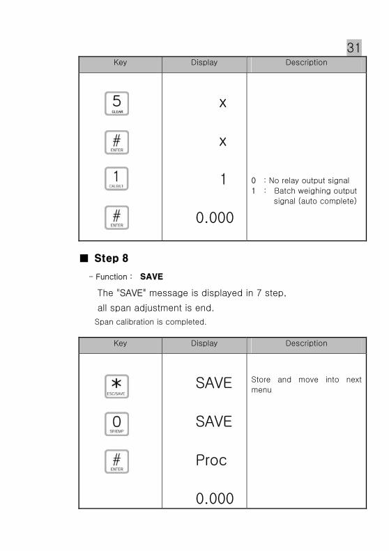
Key Display Description
x
x
1
0.000
0 : No relay output signal
1 : Batch weighing output
signal (auto complete)

24
- Function :
The "SAVE" message is displayed in 7 step,
all span adjustment is end.
Span calibration is completed.
Key Display Description
SAVE
SAVE
Proc
0.000
Store and move into next
menu
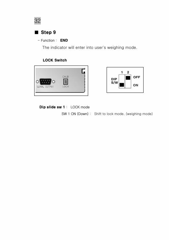
- Function :
The indicator will enter into user's weighing mode.
: LOCK mode
SW 1 ON (Down) : Shift to lock mode. (weighing mode)

25
What is Simulation Calibration?
Calibration is performed for matching the BS-7220 to a strain-gage
sensor. The following two type of calibration are available for the BS-
7220.
Equivalent input Calibration.
Calibration is performed without an actual load by entering the rated
output value (mV/V) and the capacity (to be indicated) of the strain-
gage sensor by the keys. Calibration is easily performed when no actual
load is available.
For example, the gain is automatically determined by entering.
2.0000mV/V (rated output)-100.0kg (capacity)
as indicated for a load.
1 Step : Calibration Mode Set
2 Step : Minimum Division Set
3 Step : Decimal Point Set
4 Step : Maximum Capacity Set &
Rated Output value Set
5 Step : Zero Calibration
6 Step : Digital Filter Value Set
7 Step : Relay mode Set
8 Step : Save
9 Step : END
- Function :

26
: CALIBRATION mode
SW 1 OFF (Up) : Shift to calibration mode.
- Function :
Range → 1~ 8
A step to set up a division value.
Also this value will be displayed as 1-2-5-10-20-50-100 by each key.
So, it will be go to the next step recording the position.
Key Display Description
x
x
1
0.000
0.001Kg (Decimal point: 3)
1 : 1,2,3,4,5…
2 : 2,4,6,8,10…
3 : 5,10,15,20,25…
4 : 10,20,30,40,50…
5 : 20,40,60,80,100…
6 : 50,100,150,200,250…
7 : 100,200,300,400,500…
8 : 200,400,800,1000…
27
REF 1.The minimum division means the value of one division.
REF 2. External resolution is obtained by division the min. division by the
maximum capacity. Set the resolution to be within 1/10,000.
- Function :
Range → 0~ 4
Key Display Description
x
3
0.000
0 (100) : 0
1 (101) : 0.0
2 (102) : 0.00
3 (103) : 0.000
4 (104) : 0.0000
- Function :
Range → 1 ~ 99,900kg
A step to set up max. weight.
It can input the maximum weight as the end-user demands instead of
discretion number.
How to input is to push ENTER key after inputting discretion number.
♣ Don’t excess (A division ÷ Max. weight) with over 1/10,000
If accessing over 1/10,000,it will appear error.

28 - Function :
Range → 1.0000 mV/V ~ 3.0000 mV/V
The display discretion number "r2.0000" (rated output 5figure)
Please input the value of standard weight for span adjustment by
numeric key.
How to input is to push ENTER key after inputting discretion number.
Key Display Description
Full Capacity Value Input
(xxxxx)
Load Cell Rated Output
Value Input (xxxxx)
xx.xxx
xx.xxx
xx.xxx
x.xxxx
x.xxxx
0.000
mV/V
REF 1. The maximum capacity means the maximum weight that scale
can measure.
REF 2. A data sheet is attached to a strain-gage sensor at the time of
purchase.
The data sheet provides data including:
capacity load(in kg, t, etc.)
rated output. Voltage(in mV/V)
non-linearity, Hysteresis, input resistance, output resistance and
zero balance.
Enter the capacity and the rated output value required for
equivalent input calibration into the BS-7220.

29
- Function :
A step to check the zero conditions of Indicator.
After appearing "ZEro", please push ENTER key.
Please do it as the zero adjustment instruction.
Key Display Description
0
ZEro
0.000
Unload the tray and press
“ENTER” key Under zero
calibration
Zero calibration is
completed.
REF 1. If the “ZERO” key is pressed, only zero calibration is completed
and program moves SAVE & EXIT mode.
please push ESC key.
- Function :
Range → 1~ 9
Adjust the set value according to the condition how many times
converted digital value read and display.
How to input is to push ENTER key after inputting discretion

30
Relay OFF
Relay ON
ON
ON
Relay Out
L1
100 Weight
Display
OFF
OFF
200
ON
OFF
---설 정----
L1 ------ 100
L2 ------ 200
L2
Key Display Description
x
x
3
0.000
1 : Less vibration
~
9 : Much vibration
- Function :
Range → 0 or 1
Two kinds of way of input set point are available.
This key is used for sum of unit weight and relay mode or numeric key "5" .
Press the "5" key, appear the "x" on the unit display part.
31 Key Display Description
x
x
1
0.000
0 : No relay output signal
1 : Batch weighing output
signal (auto complete)
- Function :
The "SAVE" message is displayed in 7 step,
all span adjustment is end.
Span calibration is completed.
Key Display Description
SAVE
SAVE
Proc
0.000
Store and move into next
menu
32
- Function :
The indicator will enter into user's weighing mode.
: LOCK mode
SW 1 ON (Down) : Shift to lock mode. (weighing mode)

33
00 No motion Detection Condition
01
~
19
1 : Less vibration
~
19 : Much vibration
If weight change within
given time is not bigger
than the SET range, stable
condition is displayed..
0 No Hold
1 Peak Hold : Compute the maximum weight of
oscillating weights.
2 Average Hold : Compute the average weight of
oscillating weights.
Average Hold time : 00~29 sec
1
~
9
0
1 : Less vibration
~
9 : Much vibration
0 : Fast display
Adjust the set value
according to the condition
how many times converted
digital value read and
display.
34
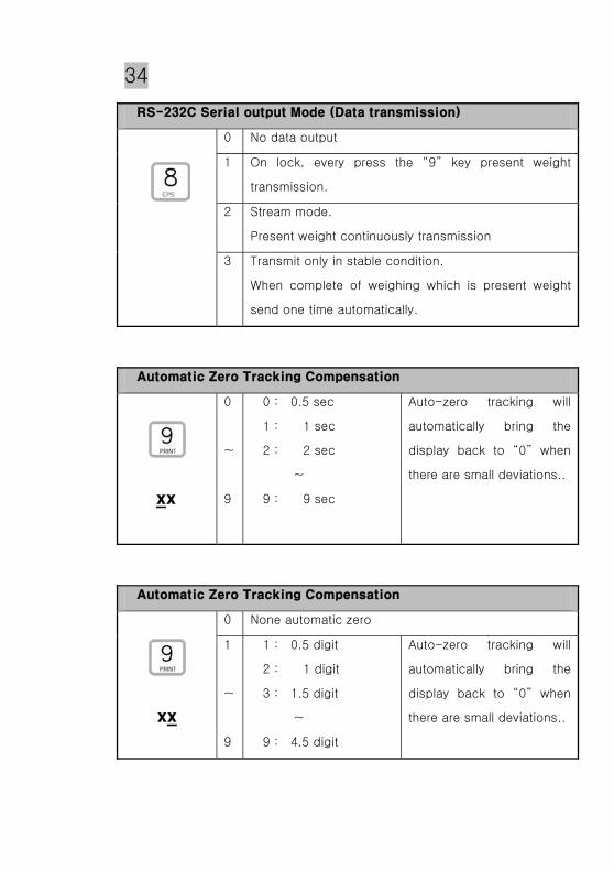
0 No data output
1 On lock, every press the “9” key present weight
transmission.
2 Stream mode.
Present weight continuously transmission
3 Transmit only in stable condition.
When complete of weighing which is present weight
send one time automatically.
0
~
9
0 : 0.5 sec
1 : 1 sec
2 : 2 sec
~
9 : 9 sec
Auto-zero tracking will
automatically bring the
display back to “0” when
there are small deviations..
0 None automatic zero
1
~
9
1 : 0.5 digit
2 : 1 digit
3 : 1.5 digit
~
9 : 4.5 digit
Auto-zero tracking will
automatically bring the
display back to “0” when
there are small deviations..
35
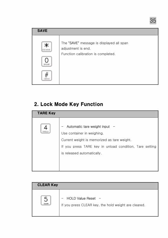
The "SAVE" message is displayed all span
adjustment is end.
Function calibration is completed.
- Automatic tare weight input -
Use container in weighing.
Current weight is memorized as tare weight.
If you press TARE key in unload condition, Tare setting
is released automatically.
- HOLD Value Reset -
If you press CLEAR key, the hold weight are cleared.
36
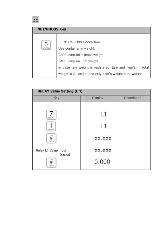
- NET/GROSS Conversion -
Use container in weight.
TARE lamp off – gross weight
TARE lamp on –net weight
In case tare weight is registered, tare and item’s total
weight is G. weight and only item’s weight is N. weight.
Key Display Description
Relay L1 Value Input
(xxxxx)
L1
L1
xx.xxx
xx.xxx
0.000
37
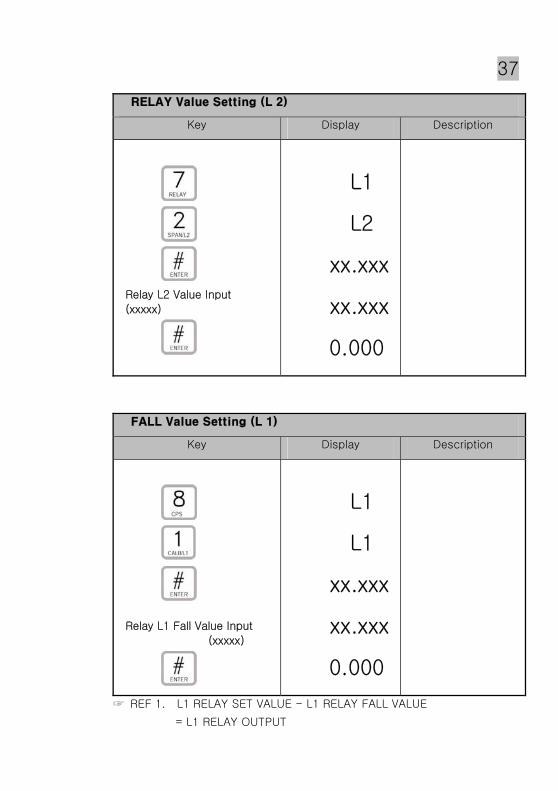
Key Display Description
Relay L2 Value Input
(xxxxx)
L1
L2
xx.xxx
xx.xxx
0.000
Key Display Description
Relay L1 Fall Value Input
(xxxxx)
L1
L1
xx.xxx
xx.xxx
0.000
REF 1. L1 RELAY SET VALUE - L1 RELAY FALL VALUE
= L1 RELAY OUTPUT

38
Key Display Description
Relay L2 Fall Value Input
(xxxxx)
L1
L2
xx.xxx
xx.xxx
0.000
REF 1. L2 RELAY SET VALUE – L2 RELAY FALL VALUE
= L2 RELAY OUTPUT
- PRINT -
By pressing “PRINT” key, ”Print” message is displayed.
Set in un-lock mode RS-232C interface “ 9 ” key : 1.
The "SAVE" message is displayed all span
adjustment is end.
Function calibration is completed.

39
0 No data output
1 Press the “9” key present weight transmission.
2 Stream mode.
3 Transmit only in stable condition.
Type : EIA-RS-232C
Method : Full-Duplex , Asynchronous, Bi-direction
Baud rate : 9600bps ( Baud-Rate )
Format : ① Data Bit : 8 (NO Parity)
② Start/Stop : 1 bit
③ Parity Bit : None
④ Code : ASCII
OUTPUT 1 2 3 4 5 6 7 8 9 10 11 12 13 14
Character CR LF ST SI DATA (8byte) CR LF
HEX Code 0D 0A +/- 0x30 -0x39 (7Byte) + .0x2E(1byte) 0D 0A
CR : 0x0D (Carriage Return, EOL)
LF : 0x0A (Line Feed, NL)
ST : 0x53 (Stable), 0X55 (Unstable), 0x50 (Peak)
SI : Sign 0x2B(+), 0x2D(-)
DATA : ASCII 8byte
Example) : 40.500kg Present weight
OUTPUT 1 2 3 4 5 6 7 8 9 10 11 12 13 14
Character CR LF U (+) 0 0 4 0 . 5 0 0 CR LF
HEX
Code 0D 0A 55 2B 30 30 34 30 2E 35 30 30 0D 0A

40
25 pin port(Female)
serial port of
computer
3 Transmit Data
2 Receive Data
5 Chassis Ground
1 Carrier Detect
4 Data Terminal Ready
6 Data Set Ready
7 Request to Send
8 Clear to Send
RXD 2
TXD 3
GND 1
2 Transmit Data
3 Receive Data
7 Signal Ground
4 Request to Send
5 Clear to Send
6 Data Set Ready
8 Carrier Detect
20 Data Terminal Ready
RXD 2
TXD 3
GND 1
9 pin port(Male)
RS-232C port of
BS-7220
9 pin port(Male)
RS-232C port of
BS-7220
9 pin port(Female)
serial port of
computer
41
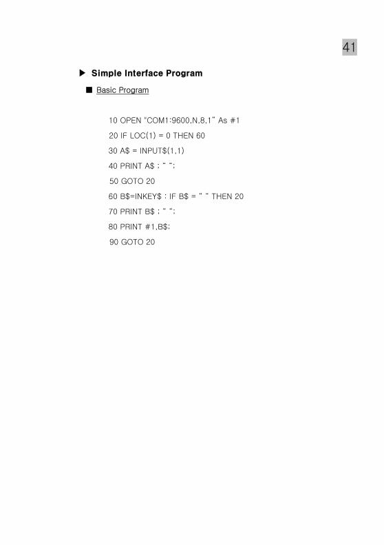
Basic Program
10 OPEN "COM1:9600,N,8,1” As #1
20 IF LOC(1) = 0 THEN 60
30 A$ = INPUT$(1,1)
40 PRINT A$ ; “ “;
50 GOTO 20
60 B$=INKEY$ : IF B$ = “ “ THEN 20
70 PRINT B$ ; “ “;
80 PRINT #1,B$;
90 GOTO 20
42
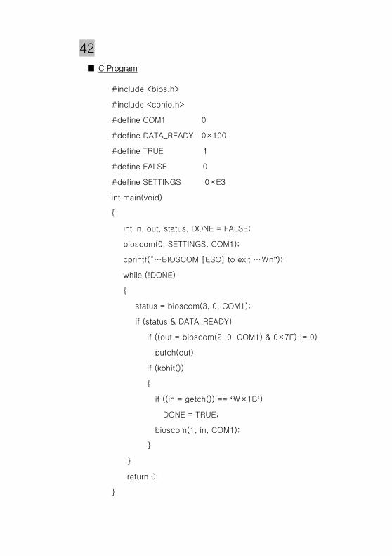
C Program
#include <bios.h>
#include <conio.h>
#define COM1 0
#define DATA_READY 0×100
#define TRUE 1
#define FALSE 0
#define SETTINGS 0×E3
int main(void)
int in, out, status, DONE = FALSE;
bioscom(0, SETTINGS, COM1);
cprintf(“…BIOSCOM [ESC] to exit …₩n”);
while (!DONE)
status = bioscom(3, 0, COM1);
if (status & DATA_READY)
if ((out = bioscom(2, 0, COM1) & 0×7F) != 0)
putch(out);
if (kbhit())
if ((in = getch()) == ‘₩×1B’)
DONE = TRUE;
bioscom(1, in, COM1);
return 0;

43
- RS-422 is to transmit the signal by the power difference.
Also, it is more safety rather other interface system for a electric noise.
- Specially please use the cable with shield coax cable surely.
- Recommended distance is under 1.2 km.
- Both end side of a wire must be connected by the termination of
300Ω.
: Same as RS-232C
: Same as RS-232C
9핀 포트 (암컷)
컴퓨터 직렬 포트
422(+) 2
422(-) 6
GND 7
2 Transmit Data (+)
15 Receive Data (-)
14 Transmit Data (-)
3 Receive Data (+)
1 Ground
7 Ground
4,5 Wire Connect
16,17 Wire Connect 9 pin port(Male)
RS-422 port of
BS-7220
25 pin serial port of computer

44
Type : EIA-RS-232C
Method : Full-Duplex , Asynchronous, Bi-direction
Baud rate : 2400bps ( Baud-Rate )
Format : ① Data Bit : 8 (NO Parity)
② Start/Stop : 1 bit
③ Parity Bit : None
④ Code : ASCII
Data Format
S T , G S , + 0 0 0 0 0 . 0 k g CR LF
Header 1 Header 2 DATA (8byte) Unit End
① Header 1
- US : WEIGHT UNSTABLE
- ST : WEIGHT STABLE
- OL : OVER LOAD
② Header 2
- GS : GROSS WEIGHT MODE
- NT : NET WEIGHT MODE
④ WEIGHT (8 byte)
- SIGNAL ( + or - )
- WEIGHT ( Included Decimal point )
- 100.0 kg : ‘0’ , ‘0’ , ‘0’ , ‘1’ , ‘0’ , ‘0’ , ‘.’ , ‘0’, - 150.5 kg : ‘0’ , ‘0’ , ‘0’ , ‘1’ , ‘5’ , ‘0’ , ‘.’ , ‘5’, - 165.3 kg : ‘-’ , ‘0’ , ‘0’ , ‘1’ , ‘6’ , ‘5’ , ‘.’ , ‘3’,
Each ASCII code of weight transmitted by 8 byte.( ‘0’ : 0 x 20)
20 mA
0 mA
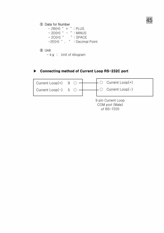
45 ⑤ Data for Number
- 2B(H) “ + ” : PLUS
- 2D(H) “ - ” : MINUS
- 2O(H) “ ” : SPACE
-2E(H) “ . ” : Decimal Point
⑥ Unit
- kg : Unit of kilogram
Current Loop(+) 9
Current Loop(-) 5
Current Loop(+)
Current Loop(-)
9 pin Current Loop
COM port (Male)
of BS-7220

46
* The voltage output occurs proportionally the voltage
according to the size of a weight
In 0V ~10V.
SPECIFICATION
Analog Out Standard Weight Selecting.
Analog max out value when weight setup.
The indicator will enter into user's weighing mode.
: LOCK mode
SW 1 ON (Down) : Shift to lock mode. (weighing mode)
output Voltage 0 ~ 10V DC out
Precision Max 1/1000
Min Impedance Over 1 kΩ

47 Key Display Description
Analog max out value input
(xxxxx)
xx.xxx
xx.xxx
xx.xxx
0.000
Adjustment
Key Display Description
ZERO VR adjustment
GAIN VR adjustment
0
ZEro
0.000
0.000
xx.xxx
xx.xxx
xx.xxx
0.000

48
The "SAVE" message is displayed all span
adjustment is end.
Function calibration is completed.
* The voltage out is to 0V when the weight is displayed 0 kg in
indicator.
* The voltage out is to 10V when the weight is displayed max.
capacity in indicator.
* If analog output is not correct,
You can make a fine adjustment with “ZERO” VR(Zero
adjustment) and “GAIN” VR(Span adjustment)
on analog pc board by multi meter.
( Recommended accuracy : 1/1,000 )

49
* The voltage output occurs proportionally the voltage
according to the size of a weight
In 4mA ~20mA.
SPECIFICATION
output Voltage 4 ~ 20 mA DC Current out
Precision Max 1/1000
Min Impedance Under 500 Ω
Analog Out Standard Weight Selecting.
Analog max out value when weight setup.
The indicator will enter into user's weighing mode.
: LOCK mode
SW 1 ON (Down) : Shift to lock mode. (weighing mode)

50 Key Display Description
Analog max out value input
(xxxxx)
xx.xxx
xx.xxx
xx.xxx
0.000
Adjustment
Key Display Description
ZERO VR adjustment
GAIN VR adjustment
0
ZEro
0.000
0.000
xx.xxx
xx.xxx
xx.xxx
0.000

51
The "SAVE" message is displayed all span
adjustment is end.
Function calibration is completed.
* How to calibrate for output rate bewteen 4mA and 20mA.
The current out is to 4 mA when the weight is displayed 0 kg
in indicator.
The current out is to 20 mA when the weight is displayed
max. capacity in indicator.
If analog output is not correct,
You can make a fine adjustment with “ZERO” VR(Zero
adjustment) and “GAIN” VR(Span adjustment)
On analog pc board by multi meter.
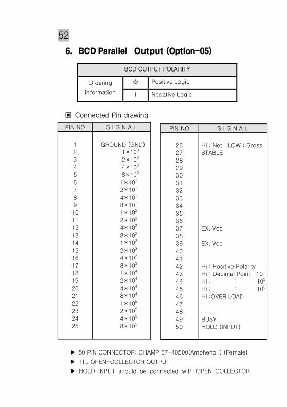
52
Connected Pin drawing
50 PIN CONNECTOR: CHAMP 57-40500(Ampheno1) (Female)
TTL OPEN-COLLECTOR OUTPUT
HOLD INPUT should be connected with OPEN COLLECTOR
BCD OUTPUT POLARITY
Positive Logic Ordering
information 1 Negative Logic
PIN NO S I G N A L
1
2
3
4
5
6
7
8
9
10
11
12
13
14
15
16
17
18
19
20
21
22
23
24
25
GROUND (GND)
1×100
2×100
4×100
8×100
1×101
2×101
4×101
8×101
1×10²
2×10²
4×10²
8×10²
1×10³
2×10³
4×10³
8×10³
1×10⁴
2×10⁴
4×10⁴
8×10⁴
1×10⁵
2×10⁵
4×10⁵
8×10⁵
PIN NO S I G N A L
26
27
28
29
30
31
32
33
34
35
36
37
38
39
40
41
42
43
44
45
46
47
48
49
50
Hi : Net LOW : Gross
STABLE
EX. Vcc
EX. Vcc
Hi : Positive Polarity
Hi : Decimal Point 101
Hi : " 102
Hi : " 103
Hi :OVER LOAD
BUSY
HOLD (INPUT)

53 TYPE or Switch Earth.
And OUTPUT DATA will hold while HOLD INPUT
Standard Accessory : Mating connector 57-30500(Ampheno1)
Male 1 EA
Weight Data
Signal Logic Weight BCD DATA OUTPUT → Positive)/Negative .
POLARITY OUTPUT → “ ― ” = L OVER → “ OVER ” = L BUSY → “ BUSY ” = L BCD HOLD → “ HOLD ” = L (INPUT)
BCD OUTPUT CIRCUIT
Voltage 30V max.
Current 30mA max.
BUSY
FULLUP RESISTANCE OUTPUT
INPUT
Weight DATA
54
OUTPUT CIRCUIT IS OPEN COLLECTOR TYPE If output demand TTL LEVEL ,insert full up - resistance to a board of
BCD OPTION When inserting a full up resistance ,please change 5v ∼ 30V in 37,39 NO Resistance and Voltage .
5V = 1 kΩ , 10V = 2 kΩ , 15V = 2.7kΩ , 24V = 5 kΩ

55
ERROR CAUSE A/S Reference.
Waving a weight
Value.
Load cell damage
Insulation
resistance
badness of load cell.
Weighing part error
Checking for Input,
Output of load cell.
Resistance Value.
Checking Insulation
Resistance value of
Load cell.
Input resistance
: about 420Ω
Output resistance
: about 350Ω
Insulation
Resistance
: over100MΩ
Load cell damage.
Checking Insulation
Resistance value of
Load cell.
(Normal Max 100MΩ or
-OL-appear)
A. Changing a
Weight value,
B. Not return to
ZERO
Appear "Ovr -2
(OVER LOAD) Disconnected to
Load Cell.
Confirm a connect of
Load cell
Checking a single wire
Of load cell cable
Weight (-) changed Load cell output
(SIG+,SIG-)changed. Load cell connector
Load cell damage
Connection Error
Load cell damage
Load cell connector
Appear "Ovr -1"
(OVER LOAD)
Excess Max weight Remove excess weight


![[XLS] · Web viewTNT ODA LIST 7220-540 7220-561 7220-582 7220-999 7230-001 7230-053 7230-999 7240-011 7240-020 7240-100 7240-103 7240-201 7240-204 7240-220 7240-272 7240-999 7250-051](https://img.pdfslide.net/doc/110x75/5ae3d8767f8b9a5d648e7b9c/xls-viewtnt-oda-list-7220-540-7220-561-7220-582-7220-999-7230-001-7230-053-7230-999.jpg)