Embed Size (px)
Citation preview
Detection of Radio Transients: ���Digital Requirements from Cosmic Ray Experiments
John Kelley
Radboud University Nijmegen, Netherlands
Lunar Radio Explorer Workshop, ESTEC 28 April 2010
Auger Engineering Radio ArrayAERA
Jörg R. Hörandel, Radboud University Nijmegen for
Auger Engineering Radio ArrayReview, Malargüe, April 2009
1.Introduction
2.Physics case
3.Site layout
4.Antennas
5.Electronics
6.Communications
7.Power harvesting and EMC
8.DAQ
9.Risk analysis
10.Management

Introduction
• Goal: impulsive radio transients on the moon – cosmic ray emission in regolith (Askaryan effect) – other sources? (talk by O. Scholten)
• Radio cosmic ray detection on Earth – emission mechanism different, but pulses similar
– experience with triggering, background rejection – modest power budget
04.28.2010 J. Kelley, LRX Workshop ESTEC 2
Radio Emission from ���Cosmic Ray Air Showers
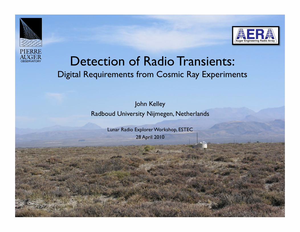
• Primary cosmic ray interacts and causes cascade of particles in atmosphere (or in the moon)
• Broadband radio pulse – width ~50 ns – due to interaction with Earth’s
magnetic field
• Emission is coherent up to 100 MHz – RF power scales as (energy)2
• Trigger on bandwidth-limited pulse
04.28.2010 J. Kelley, LRX Workshop ESTEC 3
s]µtime [2.4 2.5 2.6 2.7 2.8 2.9 3 3.1 3.2
vo
lta
ge
[m
V]
-80
-60
-40
-20
0
20
40
60
80EW
NS
pole 1
Radio Detection Station
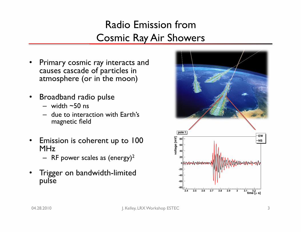
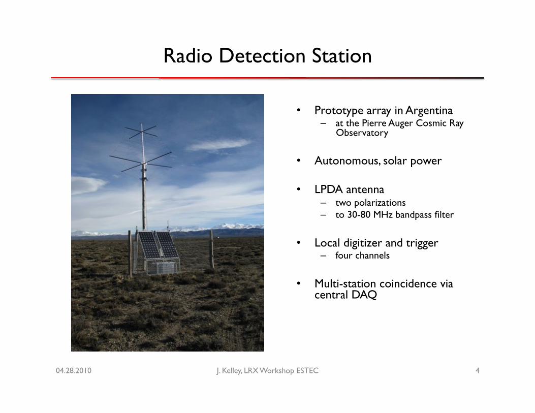
• Prototype array in Argentina – at the Pierre Auger Cosmic Ray
Observatory
• Autonomous, solar power
• LPDA antenna – two polarizations – to 30-80 MHz bandpass filter
• Local digitizer and trigger – four channels
• Multi-station coincidence via central DAQ
04.28.2010 J. Kelley, LRX Workshop ESTEC 4

Auger Engineering Radio Array
• AERA: Auger Engineering Radio Array
• 20 km2 extension to southern Auger site
• Phase I: 20 stations, June 2010 (total: 150)
04.28.2010 J. Kelley, LRX Workshop ESTEC 5
found to be within a factor of two or better. Presently, the predictions for the radio-detectorarray are at this level of precision. Further cross checks on the predicted results have beenmade by other means of parameterizations using, e.g., world data on radio measurements.
While we are using RDAS for answering the design questions of the proposed radio detectorarray, a task force is integrating the radio software into the Auger Offline framework (see section7). With this effort it will be possible to simulate and reconstruct all three detector systems,surface detector, fluorescence detector, and radio detector, within one framework, allowing forcross checks and combination of complementary shower information.
5 Site layout
It is proposed to set up the radio antenna array at the site of the AMIGA array. The situationis outlined in Fig. 11. For reference, tank names of the surface array are indicated. The largehexagon indicates the position of the AMIGA infill array (water-Cherenkov detectors) and thesmaller hexagon represents a possible infill to the infill array. These arrays are located in thefield of view of the HEAT fluorescence telescopes (the latter are just outside the left border ofFig. 11). In the map the position of the CRS, an abandoned train station, a high voltage powerline, and a fence are indicated.
fence
power line
fence
popo
trainstation
CRSHEAT
Figure 11: Layout of the proposed antenna field.
Baseline parameters for the antenna array are about 150 antennas distributed over an areaof approximately 20 km2. It is assumed that the construction will be divided into three stages,starting with about 22 antennas in a prototype cluster, followed by further 52 antennas, andfinally 85 antennas. In the map, the locations of the antennas are marked as red boxes. Boxeswithout border correspond to stage 1, black borders to stage 2, and white borders to stage 3.To record large event numbers over the whole energy domain (E > 1017.2 eV), the configurationincludes several antenna spacings. Regions with high antenna density should be to the left-handside of the area, close to the HEAT fluorescence telescopes.
Different layout scenarios have been investigated and detailed in Ref. [32]. The proposed
27
The Site
• ~20 km2
• ~150 antennas
• operation together with infill/HEAT/AMIGA
• three antenna spacings to cover efficiently 17.2 < lg E < 19.0
• three deployment stages (22 + 52 + 85 antennas)
• CRS: central container for DAQ & workshop; solar power2
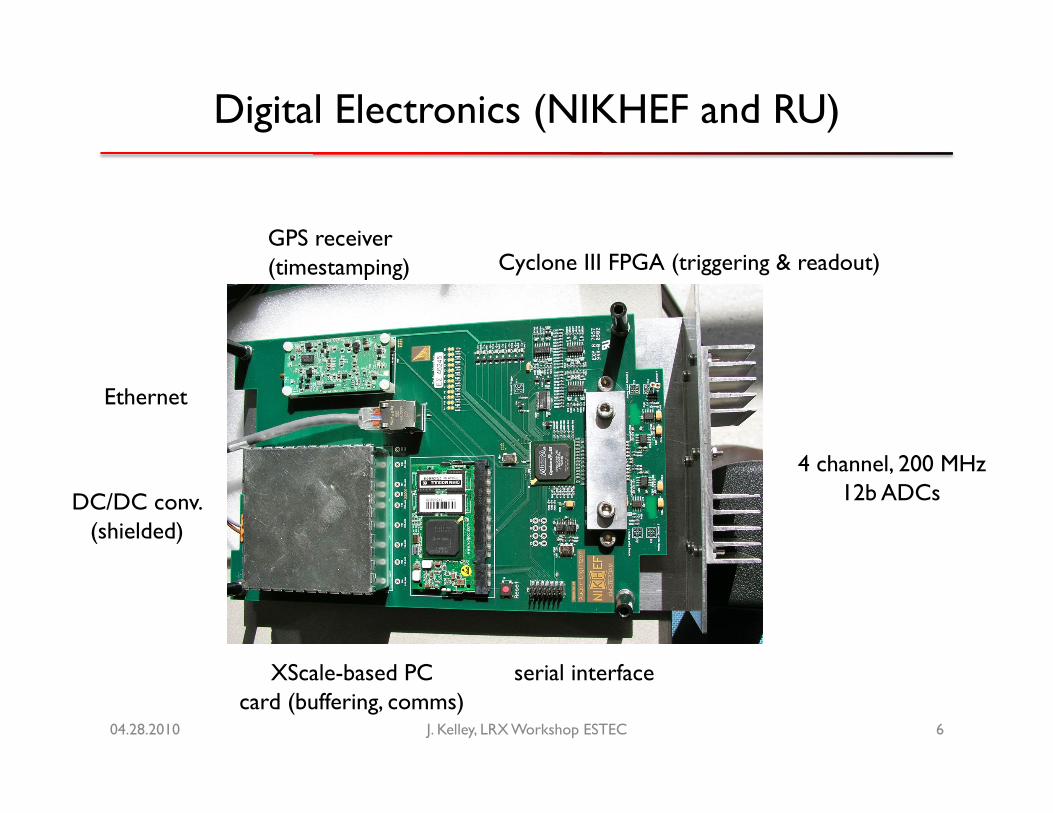
Digital Electronics (NIKHEF and RU)
J. Kelley, LRX Workshop ESTEC 6
GPS receiver (timestamping) Cyclone III FPGA (triggering & readout)
4 channel, 200 MHz 12b ADCs DC/DC conv.
(shielded)
XScale-based PC ���card (buffering, comms)
Ethernet
serial interface
04.28.2010
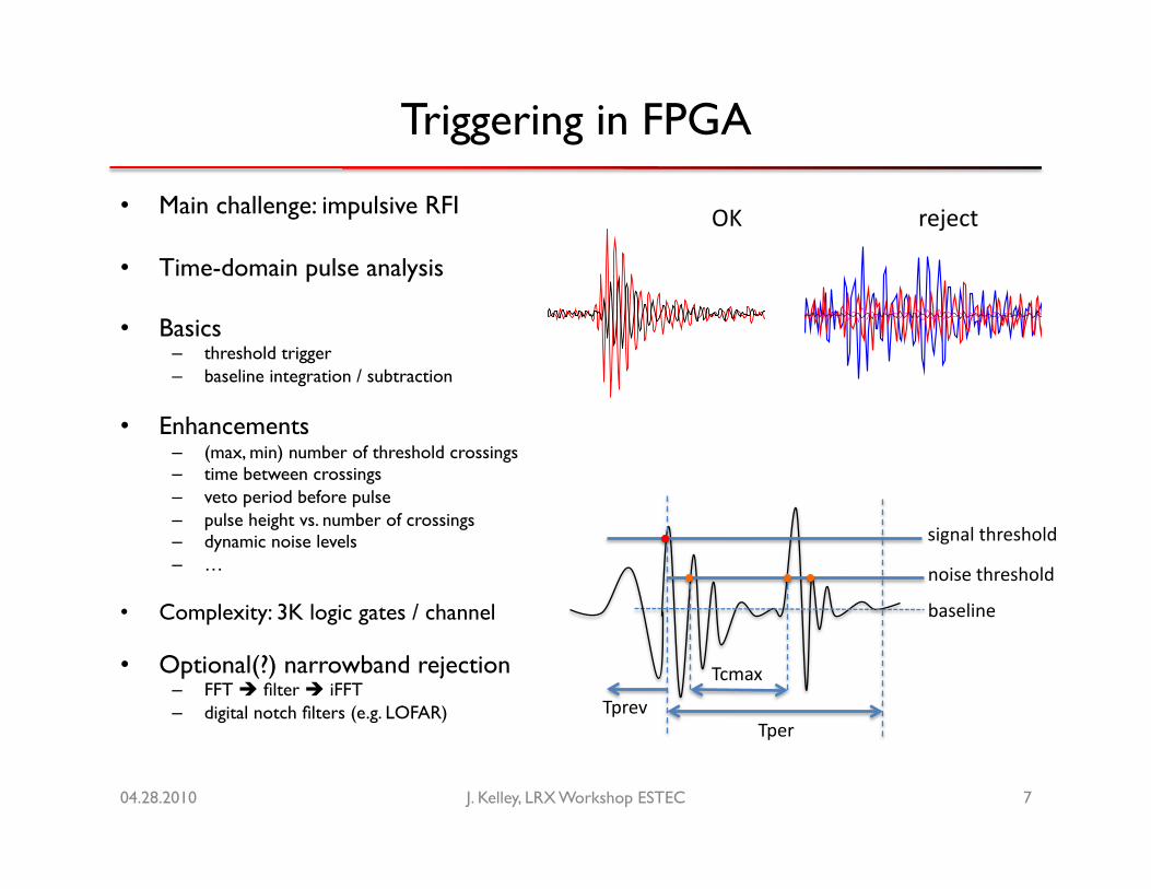
Triggering in FPGA
• Main challenge: impulsive RFI
• Time-domain pulse analysis
• Basics – threshold trigger – baseline integration / subtraction
• Enhancements – (max, min) number of threshold crossings – time between crossings – veto period before pulse – pulse height vs. number of crossings – dynamic noise levels – …
• Complexity: 3K logic gates / channel
• Optional(?) narrowband rejection – FFT filter iFFT – digital notch filters (e.g. LOFAR)
04.28.2010 J. Kelley, LRX Workshop ESTEC 7
signal threshold
noise threshold
baseline
Tper
Tcmax
Tprev
1820 1840 1860 1880 1900 1920 1940 1960 1980 2000 2020
1700
1800
1900
2000
2100
2200
2300
2400
2500
Graph
hFFT0Entries 1024Integral 1.587e+06
0 10 20 30 40 50 60 70 80 90 100
10
210
310
410
hFFT0Entries 1024Integral 1.587e+06
hFFT0
OK reject
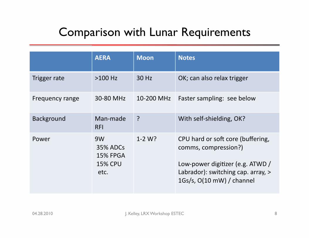
Comparison with Lunar Requirements
04.28.2010 J. Kelley, LRX Workshop ESTEC 8
AERA Moon Notes
Trigger rate >100 Hz 30 Hz OK; can also relax trigger
Frequency range 30-‐80 MHz 10-‐200 MHz Faster sampling: see below
Background Man-‐made RFI
? With self-‐shielding, OK?
Power 9W 35% ADCs 15% FPGA 15% CPU etc.
1-‐2 W? CPU hard or so[ core (buffering, comms, compression?)
Low-‐power digi`zer (e.g. ATWD / Labrador): switching cap. array, > 1Gs/s, O(10 mW) / channel