Embed Size (px)
DESCRIPTION
failure
Citation preview

Root Cause AnalysisRoot Cause Analysis(RCA)(RCA)
An essential element of Asset Integrity Management and Reliability Centered
Maintenance Procedures
Dr Jens P. Tronskar

Definition of Root Cause Analysis (RCA)Definition of Root Cause Analysis (RCA)
Root Cause Analysis (RCA) is a structured Root Cause Analysis (RCA) is a structured process that uncovers the physical, human, process that uncovers the physical, human,
and latent causes of any undesirable and latent causes of any undesirable event in the workplace.event in the workplace.
Can be;Can be;••Single or multidiscipline casesSingle or multidiscipline cases••Small or large casesSmall or large cases

Some other definitions
Failure Mode – The effect by which a failure is observed on the failed item
Failure – The termination of its ability to perform a required function
Failure Effect – The consequence(s) a failure mode has on the operation, function, or status of an item.
Failure Cause –• The physical or chemical
processes, design defects, quality defects, part misapplication, or other processes that are the basic reason for failure or that initiate the physical process by which deterioration proceeds to failure.
• The circumstances during design, manufacture, or operation that have led to a failure.

Edit in Veiw > Header and footer Edit in Veiw > Header and footerSlide 4
Root Cause (RCA)Root Cause (RCA)
Indispensible component of proactive and reliability centred maintenanceUses advanced investigative techniquesApply correctivesEliminates early life failuresExtends equipment lifetimeMinimizes maintenance

Traditional maintenance strategies Traditional maintenance strategies tend to neglect something important:tend to neglect something important:
Identification and correction of the underlying problem.

A Root Cause Analysis will disclose:A Root Cause Analysis will disclose:
Why the incident, failure or breakdown occurredHow future failures can be eliminated by:– changes to procedures– changes to operation– training of staff– design modifications– verification that new or rebuilt equipment is free of defects
which may shorten life- repair and reinstallation is performed to acceptance standards- identification of any factors adversely affecting service life and
implementation of mitigating actions

Improved availability “upImproved availability “up--time” time” and increased productionand increased production
Reactive Periodic Predictive maintenance/ (connditionmonitoring
Proactive Maintenance
Strategies RCFA
Era of maintenance
strategies
Todays’ level
Production

Reactive maintenanceReactive maintenance
• Run the equipment until breakdown• Overhaul and repair• Extensive unplanned downtime and recurrent
repair

Periodic maintenancePeriodic maintenance
Scheduled calendar or interval-based maintenanceExpensive components exchanged even without signs of wear or degradationUnexpected failures with incorrect schedules and component change-out

Predictive maintenance by Predictive maintenance by condition monitoringcondition monitoring
Apply technologies to measure the condition of machinesPredict when corrective action should be performed before extensive damage to the machinery occurs

Short and longShort and long--term benefits of term benefits of Proactive Maintenance Strategies Proactive Maintenance Strategies involving RCFA:involving RCFA:
Optimization of service conditions:Optimization of service conditions:
Increased productionReduced downtimeReduced cost of maintenanceIncreased safety

Experience and statistical dataExperience and statistical dataMMS DATABASE
Information on equipment design and service conditionsFailure statistics i.e. MTBFDescription of service failures, approach and methods for failure investigationConsequences of failure:
Downtime/pollution and spillage/secondary damagesCauses of failuresRecommendations and remedial actions

Methods and analytical tools to identify Methods and analytical tools to identify the causes of failure or breakdownthe causes of failure or breakdown
Review background dataLoss Causation Model and RCA methods and working process
Detailed analyses of failed parts/components: Analyse service conditionsUtilise experience data from data bases or other sourcesLaboratory investigation

The Loss Causation Model
LOSS
UnintendedHarm orDamage
INCIDENT
InadequateControlled
Event
IMMEDIATECAUSES
SubstandardActs
SubstandardConditions
BASICCAUSES
PersonalFactors
Job/SystemFactors
LACK OFCONTROL
InadequateSystem
InadequateStandards
InadequateCompliance
toStandards
© Det Norske Veritas
Here the lossesoccur
A failureSomethingIs done wrongor gone wrong
The main causes…

Data CollectionData Collection
••InterviewsInterviews••Documents (paper) evidenceDocuments (paper) evidence••Parts/component evidenceParts/component evidence

Interviewing Considerations
• Where to interview• Who to interview• Condition of people
at the scene• How to handle
multiple witnesses• How to handle after
the incident• How to work with
teams

Investigation techniques• A number of named techniques that are
commonly used within RCA:– Step-method– FMEA– Bow-tie– Event Tree– Failure Tree– Interview– Fish Bone– Why-Why
• The techniques have strength and weaknesses depending on the situation.

Methods for RCA; Content
• Data Collection– Interviews– Paper and technical evidence
• Methods for RCA– STEP– FMEA– FTA

STEP 1: Register Equipment Incidents
Assess cause of failureIssue Run-Log or
Work Request in Maximo
Purpose : Register Off-spec. Operation / performance, Survey & Condition Monitoring data
Start: Trigged by off-spec. operation/performance, Survey & Condition Monitoring dataStop: Incident logged in Maximo
Perform short-term Corrective action
Register Equipment Incidents
Failure report in Maximo
Operation log
Input to Process
Expectedoutput from Process
Process control
Resources
Maintenance department
Off-spec operation / performance : • Equipment failure • Trips • Abnormalities
Off-spec operation/performance loggedin Maximo:* Equipment failures* Trips* Abnormalities
Operationdepartment
History of Condition Monitoring, Surveys, and Recommended Maintenance Action in Maximo
1
Survey/Inspections/ Audits/Reviews and Condition Monitoring by Maintenance
Maximo

STEP 2: Trigger Mechanism for RCAPurpose: Evaluate need for RCA
Start: Registered HSE issues or off-spec operation/performance incidentsStop: Start RCA
Preparemonthly report
per site
Preparequarterly report
for HQ
Input toprocess
Expectedoutputfromprocess
Process control
Resources
RecommendedRCA Case
No Action
Single incidentswith highproduction loss orrepair cost
Incidents above trigger level
Surveys, Audits,Inspection, Reviews
and Conditionmonitoring byMaintenance
Off-spec operation/performance:
EquipmentfailuresTripsAbnormalities
Single operationincidents with production
loss/repair cost > X
Off-spec operation vis-à-vis (KPI)
Multiple operatingincidents per Tag no./
Equipment type
High risk findings fromsurvey/CM
Incidents below trigger level,and mitigation not cost
effective
Plant Reliability Engineer/Senior Planning Engineer
HQ SeniorReliability Engineer
Reliability Engineer(Plant/HQ)
RAM
Do PreliminaryLCC; Actual Loss/
Cost vs Investment(Replacement)

STEP 3: Appoint the RCA Team
• Minor RCAs:– Run within a department, using the procedure
• Larger RCAs:– Leader – appointed by the Plant manager– Facilitator – reliability engineer. – Discipline(s) or specialists at specific plant
• Optional to involve:– Disciplines from other sister plants– HQ-Engineering support and technical staff– Vendor– Failure laboratories– Other 3rd parties– Specialist

STEP 4: The Root Cause Analysis

An incident is the event that precedes the loss or potential loss. This section should include a description of what happened. Include all aspects related to the incidents, like outage time, cost of repair, people involved, tools in use, operational status, weather conditions etc.
The immediate causes of an incident are the circumstances that immediately preceded the contact and can usually be seen or sensed. For example if the incident is an oil spill, the immediate cause could be a broken sealing. The Immediate Causes often are the same as the failure codes registered in Maximo.
Basic Causes are the real causes behind the immediate causes: the reasons why the substandard acts and conditions occurred, the factors that, when identified, permit meaningful management control. In case of an oil spill caused by a broken sealing, the Basic Causes could be that the sealing used was of wrong type, it had a design failure or it might be installed wrong.
Lack of Control means insufficient oversight of the activities from design to planning and operation. Control is achieved through standards and procedures for operation, maintenance and acquisition, and follow-up of these. If an oil spill has occurred because of wrong installation of a sealing, the Lack of Control could be related to inadequate procedures for checking after maintenance.
1 Description of the Incident(s)
2 Immediate Cause(s)
3 Basic Cause(s)
4 Lack of Control
The main RCA report

Loss/Incident
Immediate Causes
Basic Causes
Lack of Control

RCA reporting system

Methods for RCA
• STEP; Sequential Time Event Plotting• FMEA; Failure Mode Effect Analysis• FTA; Fault Tree
• + common sense, engineering/operational experience

STEP; Sequentially Time Event Plotting
Actors
Event 1
Event 4
Event 3
Event 2
Time line
Event 5Actor 1
Actor 2
Actor 3
Actor 4
Actor 5
Event 7
Event 6
Accident
1 2Deviation 1 Deviation 2
1. Identify actors2. Identify events3. Link 1&24. Mark Substandard
acts/deviations
…all links are AND gates

FMEA; Failure Mode and Effect AnalysisLoss/Consequence:Pump not started
No detection of failure and larger damage
Wrong signal to control unit
Loss of Pressure
Consequence System/ Component
NoneFatigueBroken axel
NoneFail to operateSensor
AlarmSignal
NoneIn off positionSwitch
Fail to operateHigh Temp. Protection
NoneUnknownFail to OperateSoft-starter
NoneWindingEl. Motor
Pressure Indicator
Corrosion/WearImpeller
Pump
CommentLikelihood(low – possible- high)
DetectionFailure CauseFailure ModeFunction/
Object

Fault Tree
• Identifies causes for an assumed failure (top event)
• A logical structure linking causes and effects
• Deductive method• Suitable for potential risks• Suitable for failure events
What is a Fault Tree?Top
event
Component 1 And Gate
Component 2 Component 3
E3 E4
E1
A
E2
OR
AND
BasicEvent
IntermediateEvent

Which one to use?• STEP:
– For complex events with many actors– When time sequence is important
• FMEA:– Getting overview of all potential failure– Easy to use
• FTA:– Identifies structure between many
different failure causes– Non-homogenous case (different
disciplines)

Detailed analyzes of failed Detailed analyzes of failed parts/componentsparts/components

Typical examples of systems/equipment Typical examples of systems/equipment that can be analyzed:that can be analyzed:
Electrical generatorsHeat exchangersSubsea equipmentValvesControl systemsPumps
Fire and gas-detectorsSensors and measuring devicesComponents of gasturbinesCompressorsCranes and lifting equipmentWell and down hole drilling equipment

Proactive maintenance through Proactive maintenance through Root Cause Failure Analysis Root Cause Failure Analysis (RCFA)(RCFA)Maintenance strategy based on systematic and detailed knowledge of the causes of failure and breakdown
Systematic removal of failure sourcesPrevent repetitive problemsMinimise maintenance down-timeExtend equipment life

RCFA evaluates factors affecting RCFA evaluates factors affecting service performance such as:service performance such as:
Materials/corrosion/environmentChanges in operational conditionsStresses and strainsPresence of defects and their origin, nature and consequencesDesignWelding procedures and material weldability

The most common causes of The most common causes of service failures or breakdown:service failures or breakdown:
Incorrect operationPoorly performed or inadequate maintenanceIncorrect installation and bad workmanshipIncorrect repair introducing new defectsPoor quality manufacture leading to sub-standard componentsPoor design

Examples of problems disclosed Examples of problems disclosed by the laboratory investigation by the laboratory investigation as part of the RCFA:as part of the RCFA:GEARS• Incorrect material• Incorrect heat treatment• Incorrect design• Incorrect assembly• Corrosion• Lubricating problems
• Vibration• Incorrect surface
treatment• Geometric imperfections• Incorrect operation• Fatigue or overloading

Examples of problems disclosed Examples of problems disclosed by the laboratory investigation by the laboratory investigation as part of the RCFA:as part of the RCFA:BOLTS• Indoor material• Poor design• Manufacturing defects• Incorrect assembly• Corrosion• Vibration
• Poor or incorrect surface treatment
• Geometric imperfections• Incorrect application• Incorrect torque or
overloading

Examples of problems disclosed Examples of problems disclosed by the laboratory investigation by the laboratory investigation as part of the RCFA:as part of the RCFA:BALL-/ROLLER BEARING• Poor design• Manufacturing defects• Poor alignment and
balance• Seal failure• Electrical discharge
(arcing)
• Overload• Inadequate lubrication• Vibration• Contamination• Fretting• Corrosion

Root Cause Failure Analysis Root Cause Failure Analysis Disclosed Failure of:Disclosed Failure of:
MAIN BEARING• Heavily worn raceway, cracking of
casehardened surface, plastic deformation of sealing groove
• The main cause of failure was overloading of the bearing.Actions/recommendation:
• Reanalysis by FEM and redesign

Root Cause Failure Analysis Disclosed Root Cause Failure Analysis Disclosed Failure of:Failure of:
O-RING • Four gas leaks on TLP
platform equipment in HP & IP service
• Caused by explosive decompression (ED) of O-Ring
• Actions/recommendation:Change to another O-Ring type with other elastomer

Examples of problems disclosed by Examples of problems disclosed by the laboratory investigation as part the laboratory investigation as part of the RCFA:of the RCFA:DRIVE SHAFTS• Incorrect material quality • Incorrect design• Poor quality manufacture• Geometric imperfections• Incorrect operation
Surface defects CorrosionIncorrect balance and alignmentIncorrect assemblyFatigue or overloading

ROOT CAUSE FAILURE ANALYSIS ROOT CAUSE FAILURE ANALYSIS DISCLOSED:DISCLOSED:
Bearing BreakdownBearing Breakdown• Axial overloading• Thrust washers fitted in both bearing housings• Incorrect assembly
Actions/recommendation:Remove thrust washers from one bearing housings

ROOT CAUSE FAILURE ANALYSIS ROOT CAUSE FAILURE ANALYSIS DISCLOSED:DISCLOSED:
Gear BreakdownGear Breakdown• Broken gear tooth. Fatigue initiated from
quench cracks.• Fabrication induced defects (Basis for
discussion of liability and subsequent claims against manufacturer)Actions/recommendation:Fitting of new gears where heat treatment and case hardening procedure had been verified to be correct

ROOT CAUSE FAILURE ANALYSIS ROOT CAUSE FAILURE ANALYSIS DISCLOSED:DISCLOSED:
Damaged pinion and gear wheelDamaged pinion and gear wheel
Severe surface deformation on one side of teethNo surface hardeningIncorrect lubricationActions/recommendations:Renew gear wheel and pinion with components that have been verified to have correct surface hardening. Change lubricant and revise lubrication procedure.

Typical componentsTypical componentsthat can be that can be analysedanalysed
GearsBearingsBolted connectionsShaftsImpellers Pistons/cylinders
Motor rotors/statorsPressurized components and pressure vesselsSteel wire ropesHydraulic componentsWelded joints

Reliability assessment
Process-2
SW:
Management
Operator
Other..
… considering total system reliability!
Process-1

STEP
(Sequentially Time Event Plotting)

STEP Method
• Capturing of the sequential events leading up to an accident.
• Can be a simple timeline• Investigation of larger incidents/accidents where the
time sequence is important• Handles complex events with:
– several actors– several events in parallel– a longer time horizon
• Should include both equipment, control and human actions
(Sequentially Time Event Plotting)

STEP; Sequentially Time Event Plotting
Actors
Event 1
Event 4
Event 3
Event 2
Time line
Event 5Actor 1
Actor 2
Actor 3
Actor 4
Actor 5
Event 7
Event 6
Accident
1 2Deviation 1 Deviation 2
1. Identify actors2. Identify events3. Link 1&24. Mark Substandard
acts/deviations
…all links are AND gates

Example of a simple STEP diagramTimeActors
Missed annular inspection of valve sealing
Sealing becomes dry and brittle
Inadequate tightening
Oil leakage
January May June
Engineer
Sealing
Valve
1
OperatorManually Moving the valve
Case: Manual valve
oil leakage
Deviation 1

FMEAFailure Mode and Effect Analysis
FMECAFailure Mode and Effect Criticality
Analysis
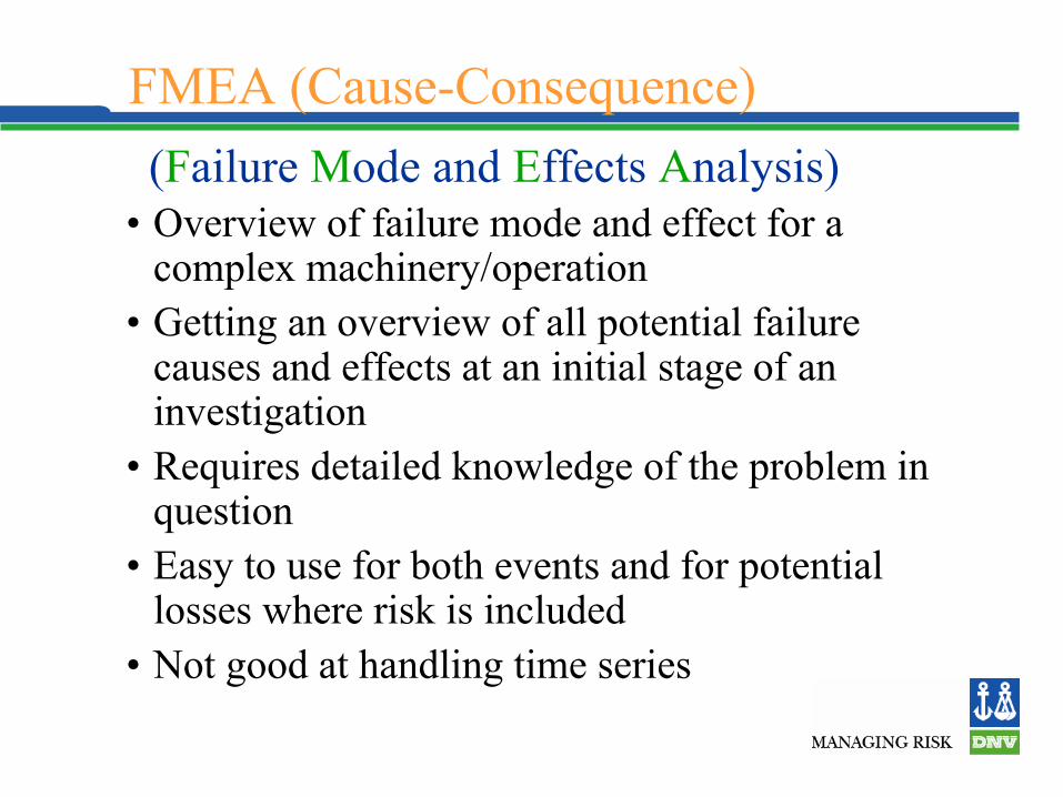
FMEA (Cause-Consequence)
• Overview of failure mode and effect for a complex machinery/operation
• Getting an overview of all potential failure causes and effects at an initial stage of an investigation
• Requires detailed knowledge of the problem in question
• Easy to use for both events and for potential losses where risk is included
• Not good at handling time series
(Failure Mode and Effects Analysis)

Technique/Working ProcessAnalysis Goal
System definition•System boundaries•Operational state•Limitations, assumptions
System description•Documentation•Division into sub-systems (e.g. functional decomposition)
Analysis planning•Find expert team•Plan expert sessions (when, what, who?)•Make documentation available
Expert sessions•Guided brain-storming to collect information•Fill in forms
Likely Causes
Exclusion
Final Causes
Evidence Finding•Inspections•Failure Analysis•Interview

Cases/ExamplesCases/Examples

Offshore Gas productionStatistics from 320 incidents/ “RCA” cases
Personal related26 %
Lack of management of
work15 %
Design33 %
Preventive Maintenance
8 %
Other18 %
Total Losses; Ca. 100 mill$/yr

Immediate causes
Immediate Causes - Substandard Acts
0
5
10
15
20
25
A14.1: Operator in
itiated fa
ilure
A10.1: Erro
r during maintenan
ce/repair
A13.1: Violation of o
peration proc
edures
A13.4: Failure durin
g praparation fo
r maiten
ance
A13.3: Violation of w
orking prce
dures
A11.1: Operator o
verlookin
g contro
l signals
A10.3: E
quipment damaged
during co
nstgruc
tiun
Too slow operator reactio
n
Error d
uring te
sting
Work without workp
ermit
Immediate Causes - Substandard Conditions
0
20
40
60
80
100
120
140
160
180
A1.3: Failure duringservice
A1.4: Failure duringstartup
A1.5: Failure duringmainteannce
N

Basic CausesBasic Causes - work related
010203040506070
Bad de
sign
Insiffi
cient
PM
Insuff
icient
plann
ing o...
Insuff
icient
QA after
...
Insufi
cient C
M
Operat
ional
respo
nse
QA of work
Plannin
g of m
ainten
ance
QA at deli
very
Change
in SW/de
sign .
..
Proced
ure/work
desc
ri...
No
of e
vent
s
Basic Causes - Personal Factors
05
10152025
Lack
of ex
perie
nce
Lack
of jo
b rela
ted ...
Lack
of in
fo/dra
wings
Stress
full w
ork si
tua...
Lack
of su
pport
Job r
elated t
raining
Lack
of kn
owled
ge

Explosion and fire at refinery

Refinery Explosion & Fire
Localised Corrosion in overhead Piping
Debutanizer Column
Debutanizer Overhead Receiver

Longford Longford GasplantGasplant

Rich oil de-ethanizer reboiler

Root Cause Failure Analysis
BRITTLE FRACTURE IN CHANNEL
TO TUBESHEET WELD
• Low temperature due to process upset • caused brittle fracture initiation from root • of weld containing lack of fusion defect
• Actions/recommendations:Actions/recommendations:• Reconstruct using low temperature steel • grade, carry out proper UT. Modify operation • procedure and controls to prevent • future process upsets. Damage mechanism: Damage mechanism:
Brittle fractureBrittle fracture
DISCLOSED:

RCFA of LNG Plant Failure

RCFA of LNG Plant Failure

RCFA of WHRU

Metallurgical investigation

Findings
• Explosion caused by trip of turbine and leak from WHRU gas coil to header weld
• Following gas leak, auto-ignition of air/gas mixture occurred. The auto-ignition temperature was equal to the surface temperature of the equipment based on instrument readings
• Weld failure due to creep/fatigue and time dependent embrittlement of weld HAZ
• Damage was caused by air/gas mixture explosion equivalent to 68 kg TNT

Failure of 24” OD subsea clad pipeline

Corrosion in 24” OD clad pipeline