Embed Size (px)
Citation preview

8th International Symposium on Friction Stir WeldingMARITIM Seehotel Timmendorfer Strand, Germany
The Influence of Friction Stir Weld Tool Form and Welding Parameters on Weld Structure and Properties: Nugget Bulge in Self-Reacting Friction Stir Welds
Author Details:Surname Schneider First name JudyCompany Mississippi State UniversityAddress Mechanical Engineering Department
Town Mississippi StatePostcode MS 39762 Country USATelephone 662-325-9154 Email [email protected]
Co-author (1):Surname Nunes First name ArthurCompany NASA MSFCTown Marshall Space Flight
CenterCountry USA
Telephone 256-544-2699 Email [email protected]
Co-author (2):Surname Brendel First name MichaelCompany University of IllinoisTown Urbana-Champaign Country USATelephone 256 961-0032 Email [email protected]
SYNOPSIS (~500 words)
The Influence of Friction Stir Weld Tool Form and Welding Parameters on Weld Structure and Properties: Nugget Bulge in Self-Reacting Friction Stir
Welds
J.A. Schneider1, A.C. Nunes, Jr2., and M.S. Brendel3
1 Mississippi State University2 NASA Marshall Space Flight Center
3 University of Illinois at Urbana-Champaign
Although friction stir welding (FSW) was patented in 1991, process development has been based upon trial and error and the literature still exhibits little understanding of the mechanisms determining weld structure and properties. New concepts emerging from a better understanding of these mechanisms enhance the ability of FSW engineers to think about the FSW process in new ways and must inevitably lead to advances in the technology.
A kinematic approach in which the FSW flow process is decomposed into several simple flow components, a translation, a rotation of a plug of metal adjacent to the tool, and a ring vortex flow component surrounding the tool, has been found to explain the basic structural features of FSW welds and to relate them to tool geometry and welding parameters.
https://ntrs.nasa.gov/search.jsp?R=20100024372 2018-03-24T16:31:28+00:00Z

8th International Symposium on Friction Stir WeldingMARITIM Seehotel Timmendorfer Strand, Germany
Recently this kinematic concept has been applied to the "self reacting" (SR)-FSW process (See Figs. 1 and 2), in which the weld metal is grasped between shoulders attached to and rotating with the weld tool and does not require a heavy supporting anvil to balance a plunge load applied from one side only as in the "conventional" (C)-FSW process.
Figure 1. Tool geometry for a SR FSW tool. Figure 2. Basic material flow model.
A correlation between the lateral bulging of the nugget, the grain-refined region in the weld center, and the strength of the weld was found in a set of empirical SR-FSW data. Nugget material is generated by the very high shear deformation rate imposed on the weld metal as it is engulfed by and abandoned by the rotating plug of metal adjacent to the tool. The central bulge is a distortion of the nugget caused by the ring vortex flow component (See Fig. 2). A very rough estimate of the extent of bulge can be computed in terms of weld parameters and certain geometric features of the SR-FSW tool.
Because of the correlation of bulge with strength, the bulge computation relates weld parameters and tool geometry to weld strength. This correlation presents a way to select parameters and geometry so as to optimize weld strength. It also provides clues that may ultimately explain why the weld strength varies within the sample population.
The Influence of Friction Stir Weld Tool Form and WeldingParameters on Weld Structure and Properties: Nugget Bulge in
Self-Reacting Friction Stir Welds
J.A. Schneider, Mississippi State University, Mississippi State, USA
A.C. Nunes, Jr., NASA, Marshall Space Flight Center, USA
M.S. Brendel, University of Illinois, Urbana-Champaign, USA
SYNOPSIS
Although friction stir welding (FSW) was patented in 1991 [1], process development hasbeen based upon trial and error and the literature still exhibits little understanding of themechanisms determining weld structure and properties. New concepts emerging from abetter understanding of these mechanisms enhance the ability of FSW engineers to thinkabout the FSW process in new ways, inevitably leading to advances in the technology.
A kinematic approach in which the FSW flow process is decomposed into several simpleflow components has been found to explain the basic structural features of FSW welds andto relate them to tool geometry and process parameters [2, 3]. Using this modellingapproach, this study reports on a correlation between the features of the weld nugget,process parameters, weld tool geometry, and weld strength. This correlation presents a wayto select process parameters for a given tool geometry so as to optimize weld strength. Italso provides clues that may ultimately explain why the weld strength varies within thesample population.
INTRODUCTION
Development of friction stir welding parameters has relied on a “trial and error” approachtoward establishing process parameters and weld tool design. Process parameter rangesare typically established by FSWing over a range of RPM and travel speeds in fixeddisplacement control mode, allowing the load to vary as needed. Most reported studies donot consider or provide sufficient details of the weld tool for assessing possible relationshipsbetween the process parameters and the tool geometry. Tensile tests and microstructuresare analyzed to distinguish “good” from “bad” welds. The basis for determining “bad” weldsis either low tensile property data or structural defects. Several studies have been publishedwhich attempt to relate process parameters, typically through torque [4], or energy [5-7]applied to the weld, with “good welds”.
Defects generally comprise internal voids, joint line remnants, and root flaws. Genericprocess maps have been developed which suggest that not all weld defects result from asingle source outside of a “good parameter” envelope [8. 9]. Trends have been reported inthe literature in which defects are reduced with increasing travel speed for a given tooldesign [10, 11]. Although opposite trends between welding speed and defect formationhave been reported to occur among different aluminium alloys [11].

The weld temperature has been reported to be chiefly dependent on the tool rotation speed[12]. At higher tool rotations, more material is reported to be involved in the nuggetformation which is attributed to hotter temperatures promoting a wider area of plasticizedmaterial flow [13]. A pseudo heat index (PHI) has been proposed to quantify the heat inputlevel required to eliminate defects [14, 15]. However, other studies have reported holdingthis index constant does not produce welds of similar quality [16].
Attempts to relate tool geometry to weld quality have focused on smooth, threaded, ortapered pin tool surfaces, with or without flats [17-28]. No consistency has been reported inthe literature regarding trends in the formation of defects associated with tool geometry otherthan that use of threads on the pin tool appear to mitigate the formation of defects [17, 23,27]. Most of these studies have used a threaded pin with a smooth shoulder [17-28].Threads on the pin tool have also been credited with promoting a vortex motion whichstabilizes the rotational zone which reduces voids or lack of fusion [17, 23, 27]. Coarserpitch pins are reported to promote a larger working volume or volume of material influencedby the action of the pin tool [24].
Several researchers have distinguished between shoulder-flow- induced and pin-flow -induced flow defects [29-33]. If the defect occurs on the advancing side (AS), it is reportedto be related to insufficient shoulder flow to fill a cavity left in the wake of the weld [29, 30].The shoulders in these studies are assumed to be smooth due to the reported use of a leadangle on the tool. Several studies which use scrolled shoulders note similar defectsalthough they attribute the defect to inadequate plunge load [33].
BODY OF PAPERProcess Modeling
A kinematic model [2] will prove useful in interpreting the experimental data obtained in thisstudy. This approach conceives of a rotating plug of metal attached to the weld tool andtranslated along the weld seam with the tool. The rotating plug of metal is bounded by thetool surface and a shearing surface, observed to be very thin, separating the rotating plugfrom the fixed body of weld metal outside the plug. Figure 1 illustrates the metal flowcrossing this boundary which is exposed to a very high shear strain rate (y) given inequation 1 that is dependent on the pin radius (R), tool rotation (w) and shear zone thickness(S). Typical strain rates predicted in the range of 10 3 to 105 s-1 approach those of ballisticconditions in which like grain refinement has been reported [34, 35]. . As the rotating plugmoves along the weld seam, it entrains elements of metal, rotates them, and abandons themin the wake of the weld tool.
Shear Zone
R*Wn
8=
s[eq.1]
Flow Stream
R*W ` IY = V [eqn. 2] \ti .y 1
Ω
r \ ti 4 V
1
S
Figure 1. Metal entering severe shear zone surrounding tool.

The increment of shear strain (y) the metal experiences as it enters the severe shear zonecan be approximated using equation 2 where V is the tool travel velocity. At the reportedtemperatures range of 0.8-0.9 times the solidus melting temperature (Tmp) of the alloy, theflow stress of the metal is almost uniform in the close vicinity of the tool and shear surface[36]. Because the metal flow stress depends mostly on temperature, only minor variations inthe flow stress are also expected close to the tool.
The weld tool typically has a threaded pin which creates a ring vortex velocity field withpronounced axial as well as radial flow velocity. This axial field component is responsible forretaining metal within the rotating plug during multiple revolutions as reported in otherstudies where markers have traced out metal paths rotating multiple times around the weldtool [37]. The ring vortex flow field adds perturbations of its own to the weld macrostructure.The kinematic model relates weld parameters and tool geometry to weld structure and offersways to control weld structure to eliminate defects.
This kinematic concept has been applied to the both the conventional (C)-FSW and selfreacting (SR)-FSW process as illustrated in Figure 2. The C-FSWing process reacts theforces generated by the tool against a backing anvil whereas the SR-FSW process graspsthe metal between shoulders attached to and rotating with the weld tool to eliminate theneed for the supporting anvil. The SR-FSW process is modeled as two mirrored, back-to-back C-FSW processes.
(a)
(b)
Figure 2. Comparison of conventional (C)-FSW process (a) versus the self-reacting (SR)-FSW process (b). Note the absence of the backing anvil in the SR-FSW process.
Experimental Procedure
The SR-FSWed butt welds in this study were made in 0.357” thick panels of 24” longAA2195-T87 panels. Table I summarizes the range of process parameters evaluated atconstant pinch force. A single scrolled shoulder was used on the root and crown sides witha 1.2” in diameter and an inward inverse thread pitch of 0.12”. A left hand (LH)/right hand(RH) threaded tool pin was used with a 0.5” in diameter and inverse thread pitch of 0.07”.The LH/RH configuration served to push material toward the center of the workpiece platethickness.

Table I. Summary of SR-FSWing process parameters.
SpecimenID
Processpitch (rev/in)
A1 9.1A1 13.6A3 18.2E1 22.7E2 27.3E3 31.8131 7.1B2 10.7G1 12.5B3 14.3G2 16.1
Representative transverse cross sections were prepared from each weld panel usingstandard metal lographical processing. A Keller’s etch was used to reveal themacrostructure.
Standard 1” wide tensile bars were prepared and tested in room temperature, uni-axial testsconducted perpendicular to the welding direction. The tensile tests were run in accordancewith ASTM standard E8 [38].
Results and Discussion
Figure 3 shows three representative transverse sections from the SR-FSW specimens in thisstudy with pronouncedly different nugget shapes. The profile of the weld nugget in Figure 3ashows an hour-glass shape with a width that extends from roughly the pin diameter at themid-plate to almost the shoulder width (more accurately the width of attachment of the weldmetal to the shoulder) at the root and crown surfaces. In Figure 3b the nugget edges“flatten” along the pin center as the heat affected zone (HAZ) moves radially out away fromthe nugget. In Figure 3c a radial bulge emerges in the previously flattened nugget edge atthe pin center.
Although the nugget geometry displays a similar profile on the AS advancing side (AS) andretreating side (RS), this study focuses on the changes to the AS profile since the sharpdemarcation between the nugget and the TMAZ makes it easier to resolve.
(a) 131 (b) G1 (c) G2
Figure 3. A variation in SR-FSW nugget as the tool rotation is increased. A pronouncedchange can be observed in the TMAZ/nugget boundary on the AS with the emergence of anugget bulge in (c).
Overlay traces of the AS profile are summarized in Figure 4 for transverse sections of aseries of SR-FSWs made with increasing tool rotation speed at constant travel and pinch
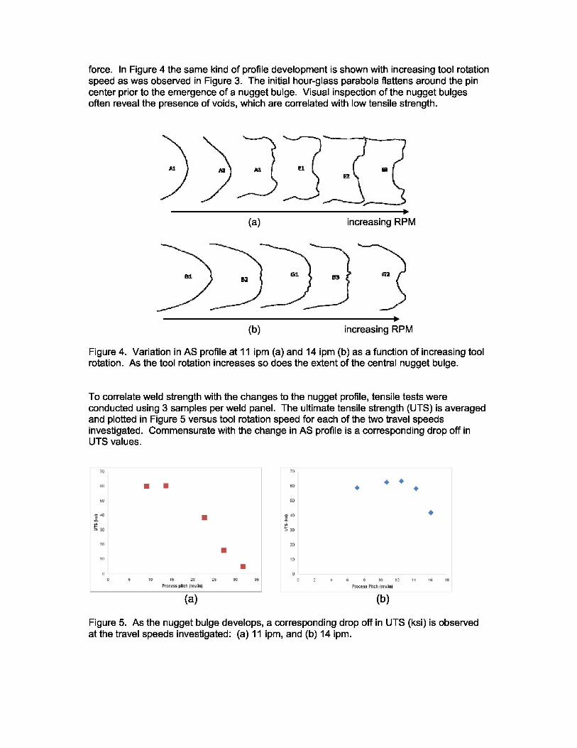
force. In Figure 4 the same kind of profile development is shown with increasing tool rotationspeed as was observed in Figure 3. The initial hour-glass parabola flattens around the pincenter prior to the emergence of a nugget bulge. Visual inspection of the nugget bulgesoften reveal the presence of voids, which are correlated with low tensile strength.
u ,, nEz
(a) increasing RPM
es si D3 ^x
B2
^r(b) increasing RPM
Figure 4. Variation in AS profile at 11 ipm (a) and 14 ipm (b) as a function of increasing toolrotation. As the tool rotation increases so does the extent of the central nugget bulge.
To correlate weld strength with the changes to the nugget profile, tensile tests wereconducted using 3 samples per weld panel. The ultimate tensile strength (UTS) is averagedand plotted in Figure 5 versus tool rotation speed for each of the two travel speedsinvestigated. Commensurate with the change in AS profile is a corresponding drop off inUTS values.
X01 L1 1_01 11-51 I'm1 1,251
^Pinre pifeFi-Ire+r.'in]l
n
(a)
n '
(b)
1301 1351 101 161 181'10 ',12 'E4', ',le(Pr ce s Pdch I.,
Figure 5. As the nugget bulge develops, a corresponding drop off in UTS (ksi) is observedat the travel speeds investigated: (a) 11 ipm, and (b) 14 ipm.

The velocity field components of the kinematic model of metal flow in the vicinity of the FSWtool explain the observed changes in nugget geometry with changes in spindle speed andweld speed. The velocity field components (with respect to the tool) include a transversevelocity field equal and opposite to the tool travel velocity, a rotation inside the shear surfaceequal to the tool rotation, and a ring vortex field with both axial and radial velocitycomponents surrounding the tool. The ring vortex field is driven by both the pin threads andthe scroll on the shoulder. A scrolled shoulder pushes the weld metal radially toward the toolcenter-line, and the pin threads force weld metal axially down the pin away the shouldertoward the weld metal central plane as illustrated in Figure 6. At the central plane theopposing axial flows from the two shoulders meet and force a radial outflow of metal at thecentral plane. Refined nugget metal is carried along by this radial flow during the timeinterval when the ring vortex flow is still active after the nugget metal exits from the rotatingplug to form a nugget bulge at the central plane of the weld metal. The resulting increase inthe nugget width is in agreement with observations of other researchers of an increase innugget region attributed to the hotter welds resulting from the spindle speeds [13]. This isnot just an increase of the amount of plasticized material involved in the FSW process, butan indication of a radial flow increment induced by tool threads or shoulder scrolls. Otherresearchers also report void formation in the region where ring vortex velocity fields interact[29, 30, 33].
In order to connect nugget bulge to weld parameters, the driving mechanism for the ringvortex circulation must be considered. It is assumed that the peripheral velocity of the ringvortex field is imposed by either the radial velocity of metal imposed by the shoulder scroll orthe axial velocity imposed by the pin threads or by their joint action. For present purposesthe coarser pitch, pin thread or shoulder scroll will be assumed dominant. Given a ringvortex circulation rate, the bulge increment depends upon how long the circulation is activefor a given weld cross section. Supposing that the circulation is active for a given androughly constant distance behind the tool, the time this distance is covered is inverselyproportional to the tool’s travel velocity along the weld. On this basis an approximaterelation between nugget bulge and tool geometry and process parameters can beconstructed. This relation is presented in equation 3, where 0 is the nugget bulge, R is thetool pin radius, (o is the tool rotation, P is the inverse pitch of the coarser thread, and V is thetravel velocity along the weld seam. Precise computations are not to be expected from therelation, but, given the correctness of the assumptions, it should yield trends.
Figure 6. Basic material flow model in SR-FSW.
ൌ z
ቀ 1 െ cos ቀ
כ ఠగ
) ) [eqn. 3]
Figure 7 shows the macrostructure of a weld exhibiting reduced strength. The hour-glassnugget shape described in Figure 3 has transformed to a simple cylinder with a mid-planebulge in Figure 7a if a very thin layer of nugget material following the shoulder contact areais ignored. Outside the nugget the coarse pancake-like parent metal grains (shaped by therolling process that formed the plate) appear to be displaced upward and outward near the

bulge and upward, then downward near the shoulder in the vortex circulation describedabove with the kinematic flow model of the FSW process. Within the bulge region(Figure 7b), banding can be observed, typical of nugget material observed in conventionalFSWs.
The edge of the nugget region traces out the residue of the shear surface as distorted bysubsequent vortex flow. A span of nugget material between shoulder surface and shearsurface implies that the weld metal is sticking to the shoulder and shearing beyond it withinthe weld metal. The minimal thickness observed in Figure 7a for the span of nugget materialbetween shoulder surface and shear surface could be a result of slippage at the shouldersurface with a layer of disturbed metal masquerading as a thin span of nugget material. Itcould also be a result of the sweeping away of the thicker parts of a nugget material span bythe ring vortex circulation. A little hump of apparent nugget material rising from the shouldersurface at the bottom left of Figure 7a and an arguable, barely perceptible hump descendingfrom the upper shoulder surface favor the “sweeping away” concept with the implication ofsticking at the shoulder surface.
Within the nugget material adjacent to the bulge region are areas containing multiple voidsas shown in Figure 7c. The details of the mechanism by which these voids form is understudy, but is not yet understood. It is known that material on the weld metal surface can beingested deep into the weld; voids might be entrained into the weld by the ring vortexcirculation. It is known that velocity gradients can produce tensile stresses which, forexample, can produce central bursts in extrusions; voids might be produced by velocitygradients in the metal flow field near the nugget.
(c)Figure 7. Image of E2 (a) showing close-up of nugget bulge (b) and associated voids inadjacent region (c).
Figure 5 shows a slight increase in UTS with increased spindle speed prior to a precipitousdrop. Nugget bulges measured from macrographs of weld structure were correlated with theweld parameters of Figure 5. A nugget bulge (S) in the range of 0.005” to 0.010” correlateswith a robust range of processing parameters yielding good strengths and avoiding theprecipitous drop in strength.
According to the hypothetical relation between tool design, weld parameters, and nuggetbulge in Equation 3 for the same tool geometry nugget bulge is a function of the process

pitch. Equation 3 was used to generate the process parameter range summarized inFigure 8 for the SR-FSWs in this study compared to the effects of using a smaller pindiameter. Currently this relationship doesn’t consider the affect of different alloys. It wouldbe expected that lower conductivity alloys would be welded within a different region of theparameter range given in Figure 8 for the same tool geometry.
Figure 8. Processing parameter window for constant pitch shoulder and varying pindiameters.
Summary
A correlation between the lateral bulging of the nugget, the grain-refined region in the weldcenter and the strength of the weld was found in a set of empirical SR-FSW data. Nuggetmaterial is generated by the very high shear deformation rate imposed on the weld metal asit is engulfed by and abandoned by the rotating plug of metal adjacent to the tool. Thetransverse bulge can be explained by a distortion of the nugget caused by the ring vortexflow component. This is in agreement with other observations in which higher RPM resultedin increased nugget area [13]. An approximately for the extent of nugget bulge can becomputed in terms of weld parameters and geometric features of the SR-FSW tool.
Because of the correlation of bulge with tensile strength, the bulge computation relates weldparameters and tool geometry to weld strength. This correlation presents a way to selectparameters and geometry so as to optimize weld strength. A nominal amount of nuggetbulge correlates with a robust operating processing parameter map. As observed, thetensile strength maximizes at the outer edge of this processing map. Thus processparameter selection on the basis of weld strength may not be robust resulting inunacceptable data scatter.

ACKNOWLEDGEMENTS
We wish to acknowledge the EM30 Welding Group at the NASA-MSFC for providing theFSW samples used in this study. One of the authors (MSB) would like to acknowledge theopportunity to participate in this research as part of the 2009 URSP program sponsored bythe NASA-MSFC EM 30 welding group. Another author (JAS) would like to acknowledgefunding provided by participation in the NASA Intergovernmental Personnel Act.
REFERENCES
1) Thomas, W.M., Nicholas, E.D., Needham, J.C., Murch, M.G., Templesmith, P.,Dawes, C.J., Friction Stir Butt Welding, U.S. Patent No. 5,460,317, 1991.
2) Schneider, J.A., Nunes, Jr., A.C., “Characterization of plastic flow and resulting microtextures in a friction stir weld,” Met. Trans. B, Vol. 35, p. 777-783, 2004.
3) Schneider, J.A., Beshears, R., Nunes, Jr., A.C., "Interfacial sticking and slipping inthe friction stir welding process", Mat. Sci. & Engr. A, Vol. 435-436, p. 297-304, 2006.
4) Pew, J.W., Nelson, T.W., Sorensen, C.D., “Development of a Torque-Based WeldPower Model for Friction Stir Welding,” FSW&P IV, eds. R.S. Mishra, M.W. Mahoney,T.J. Lienert, K.V. Jata, TMS Pub., pp. 73-81, 2007.
5) El-Domiaty, A., El-hafez, H.A., “An Energy Model for Friction Stir Welding,” MaterialsScience and Technology (MS&T) Proceedings, Detroit, MI, pp. 435-447, 2007.
6) Reynolds, A.P., Tang, W., “Alloy, Tool Geometry, and Process Parameter Effects onFriction Stir Weld Energies and Resultant FSW Joint Properties,” FSW&P, ed. K.V.Jata, M.W. Mahoney, R.S. Mishra, S.L. Semiatin, D.P. Field, TMS Pub., p. 15-23,2001.
7) Reynolds, A.P., Lindner, K., Tang, W., Seidel, T.U., “Weld efficiency and defectformation: correlation between experiment and simple models,” 6th Int’l Trends inWelding Res. Conf. Proc., ed. S. A. David, T. DebRoy, J. C. Lippold, H. Smartt, andJ. M. Vitek, Pine Mtn., GA, 2003.
8) Arbegast, W.J., “Friction Stir Welding and Processing – Current State of the Art andNeeds for the Future,” XXXIII Consolda – Congresso Nacional de Soldagemd,Caxias do Sul, RS, August 27-30, 2007.
9) Kim, Y.G., Fujii, H., Tsumura, T., Komazaki, T., Nakata, K., “Three defect types infriction stir welding of aluminum die casting alloy,” Mat. Sci. & Engr. A, Vol. 415,p. 250-254, 2006.
10) Gharacheh, M.A., Kokabi, A.H., Daneshi, G.H., Shalchi, B., Sarrafi, R., “Theinfluence of the ratio of “rotational speed/transverse speed” ((o/v) on mechanicalproperties of AZ31 friction stir welds,” Int’l J of Machine tools & Mfgt, Vol. 46, p. 1983-1987, 2006.
11) Colligan, K.J., et. Al., “Friction stir welding of thick section 5083-H131 and 2195-T8P4aluminum plates,” 3rd Int’l FSW Symp., Kobe, TWI Pub., Japan, 2001.

12) Record, H.J., et al., “A Look at the Statistical Identification of Critical ProcessParameters in Friction Stir Welding,” Welding Journal, Vol. 86, No. 4, p. 97-s to103-s,2007.
13) Mishra, R.S., Ma, Z.Y., “Friction stir welding and processing,” Mat. Sci. & Engr. R.,Vol. 50, p. 1-78, 2005.
14) Charit, I, Mishra, RS, “Abnormal grain growth in friction stir processed alloys,” ScriptaMater., Vol. 58, p. 367-371, 2008.
15) Arbegast, W.J., “Modeling Friction Stir Joining as a Metalworking Process,” HotDeformation of Aluminium Alloys III, Z. Jin, ed., TMS Pub., 2003.
16) Ren, S.R., Ma., Z.Y., Chen, L.Q., “Effect of welding parameters on tensile propertiesand fracture behavior of friction stir welded Al-Mg-Si alloy,” Scripta Mater., Vol. 56,p. 69-72, 2007.
17) Zettler, R., Lomolino, S., dos Santos, J.F., Donath, T., Beckmann, F., Lippman, T.,Lohwasser, D., “Effect of tool geometry and process parameters on material flow inFSW of an AA2024-T351 alloy,” Welding in the world, Vol. 50, No. 11/12, p. 107-116,2006.
18) Zhao, Y-H., Lin, S.-B., Wu, L., Qu, F-X., “The influence of pin geometry on bondingand mechanical properties in friction stir weld 2014 Al alloy,” Mat. Letters, Vol. 59,p. 2948-2952, 2005.
19) Zhao, Y.-H., et al., Influence of pin geometry on material flow in friction stir weldingprocess. Mat. Sci. & Tech., Vol. 22, No. 1, p. 45-50, 2006.
20) Elangovan, K., Balasubramanian, V., “Influences of tool pin profile and tool shoulderdiameter on the formation of friction stir processing zone in AA6061 aluminum alloy,”Mat. and Design, Vol. 29, No. 2, p. 362-373, 2008.
21) Elangovan, K., Balasubramanian, V., “Influences of pin profile and rotational speed ofthe tool on the formation of friction stir processing zone in AA2219 aluminum alloy”,Mat. Sci. & Engr. A, Vol. 459, p. 7-18, 2007.
22) Colligan, K.J., Xu, J., Pickens, J.R., “Welding tool and process parameter effects infriction stir welding of aluminum alloys,” FSW&P II, ed. K.V. Jata, M.W. Mahoney,R.S. Mishra, S.L. Semiatin, and T. Lienert, TSM Pub., p. 181-190, 2003.
23) McClure, J.C., Coronado, E., Aloor, S., Nowak, B.M., Murr, L.E., Nunes, Jr., A.C.,“Effect of pin tool shape on metal flow during friction stir welding,” Int’l Conf onTrends in Welding Research Proc., ASM Pub., p. 257-261, 2002.
24) Field, D.P., Nelson, T.W, “Tool geometry dependence of local texture in friction stirwelds of 7050 aluminum plate,” Mat. Sci. Forum, Vol., 408-412, p. 1507-1512, 2002.
25) Boz, M., Kurt, A., “The influence of stirrer geometry on bonding and mechanicalproperties in friction stir welding process,” Mat. & Design, Vol. 25, p. 343-347, 2004.
26) Fujii, H., Cui, L., Maeda, M., Nogi, K., “Effect of tool shape on mechanical propertiesand microstructure of friction stir welded aluminum alloys,” Mat. Sci. & Engr. A, Vol.419, p. 25-31, 2006.

27) Zhao, Y-H., Lin, S.-B., Wu, L., Qu, F-X., “The influence of pin geometry on bondingand mechanical preoprties in friction stir weld 2014 Al alloy,” Mat. Letters, Vol. 59,p. 2948-2952, 2005.
28) Lorrain, O., Favier, V., Zahrouni, H., Lawrjaniec, D., “Understanding the material flowpath of friction stir welding process using unthreaded tools,” J. Mat. Proc. Tech.,Vol. 210, p. 603-609, 2010.
29) Chen, Z.W., Pasang, T., Qi, Y., “Shear flow and formation of nugget zone duringfriction stir welding of aluminum alloy 5083-0,” Mat. Sci. & Engr. A, Vol. 474, p. 312-316, 2008.
30) Kumar, K., Kailas, S.V., “The role of friction stir welding tool on material flow andweld formation,” Mat. Sci. & Engr. A, Vol. 485, p. 367-374, 2008.
31) Scialpi, A., DeFilippis, L.A.C., Cavaliere, P., “Influence of shoulder geometry onmicrostructure and mechanical properties of friction stir welded 6082 aluminumalloys,” Mat. & Design, Vol. 28, p. 1124-1129, 2007.
32) Leal, R.M., Leitao, C., Loureiro, A., Rodriques, D.M., Vilaca, P., “Material flow inheterogeneous friction stir welding of thin aluminum sheets: effect of shouldergeometry,” Mat. Sci. & Engr. A., Vol 498, p. 384-391, 2008.
33) Yan, D.P., “Study of shoulder flow zone formation in thick section FSW of 6061 Alalloy using scroll shoulder tool,” MPhil Thesis, Auckland University of Technology,2008.
34) Czochralski, J., “Zunahme der Keimzahl mit Steingender Temperatur”, ModerneMetallkunde, 1924.
35) Kaibyshev, R., Mazurina, I., “Mechanisms of grain refinement in aluminum alloysduring severe plastic deformation,” Mat. Sci. Forum, Vol. 467-470, p. 1251-1260,2004.
36) Brick, R.M, Gordon, R.B., Phillips, A., Structure and Properties of Alloys: Theapplication of phase diagrams to the interpretation and control of industrial alloystructures, 3 rd ed., pub. McGraw Hill, p. 161, 1965.
37) London, B., Mahoney, M., Bingel, W., Calabrese, M., Bossi, R.H., Waldron, D.,FSW&P II, eds. K.V. Jata, M.W. Mahoney, R.S. Mishra, S.L. Semiatin, T. Lienert,TMS Pub., p. 3-12, 2003.
38) ASTM Standard E8, “Standard Test Methods for Tension Testing of MetallicMaterials,” ASTM International, West Conshohocken, PA, Vol. 3.01.