Embed Size (px)
Citation preview
DT20RF PROGRAMMER
DIGISTAT - Radio frequency controlled room thermostatwith twin channel digital programmerFOR GREENSTAR CDi, GREENSTAR i JUNIOR AND GREENSTAR Si MODELSALSO GREENSTAR i SYSTEM AND GREENSTAR CDi SYSTEM MODEL(ONLY WHEN USED WITH THE OPTIONAL INTEGRAL DIVERTER VALVE)
INSTRUCTION MANUALOPERATING AND INSTALLATION
UK/IE
8_716_115_495a 9/2/09 11:49 Page 1

MANUAL INFORMATION
PLEASE READ THESE INSTRUCTIONS
CAREFULLY BEFORE STARTING
THESE INSTRUCTIONS ARE APPLICABLE TOTHE WORCESTER BOSCH MODEL(S) STAT-ED ON THE FRONT COVER OF THIS MANUALONLY AND MUST NOT BE USED WITH ANYOTHER MAKE OR MODEL
THESE INSTRUCTIONS APPLY IN THE UKONLY AND SHOULD BE FOLLOWED EXCEPTFOR ANY STATUTORY OBLIGATION
IF YOU ARE IN ANY DOUBT CONTACTWORCESTER BOSCH TECHNICALHELPLINE
THIS ACCESSORY MUST BE FITTED BY ACOMPETENT PERSON. FAILURE TO COMPLYCOULD LEAD TO PROSECUTION.
LEAVE THESE INSTRUCTIONS WITH THEUSER OR AT THE APPLIANCE.
ABBREVIATIONS
CH = Central Heating
DHW = Domestic Hot Water
RF = Radio Frequency
DLS = Daylight Saving
BST = British Summer Time
GMT = Greenwich Mean Time
C = Celsius (Centigrade)
IP = Ingress Protection
V = Volt
m = metre
mA = milliAmpere
DEFINITIONS (DLS/BST)
Summer time begins: Last Sunday in March at1:00 am GMT (Clocks are put forward by 1 hour)
Summer time ends: Last Sunday in October at2:00 am BST (Clocks are put back by 1 hour)
WORCESTER, BOSCH GROUP:
TECHNICAL 08705 266241
SERVICE 08457 256206
SPARES 01905 752571
LITERATURE 01905 752556
TRAINING 01905 752526
SALES 01905 752640
WEBSITE worcester-bosch.co.uk
SYMBOLS
Central Heating
Domestic Hot Water
Radio Frequency (RF) Transmitter
PROPER BATTERY RECYCLING
Electronic devices and batteries, rechargeableor not, should not be disposed of into ordinaryhousehold waste. Instead, they must berecycled properly to protect the environmentand cut down the waste of preciousresources. Your local waste managementauthority can supply details concerning theproper disposal of batteries.
PROTECT YOUR ENVIRONMENT
OPERATING & INSTALLATIONINSTRUCTIONS
DT20RF PROGRAMMERINSTRUCTION MANUAL8 716 115 495a (02.2009)
8_716_115_495a 9/2/09 11:49 Page 2
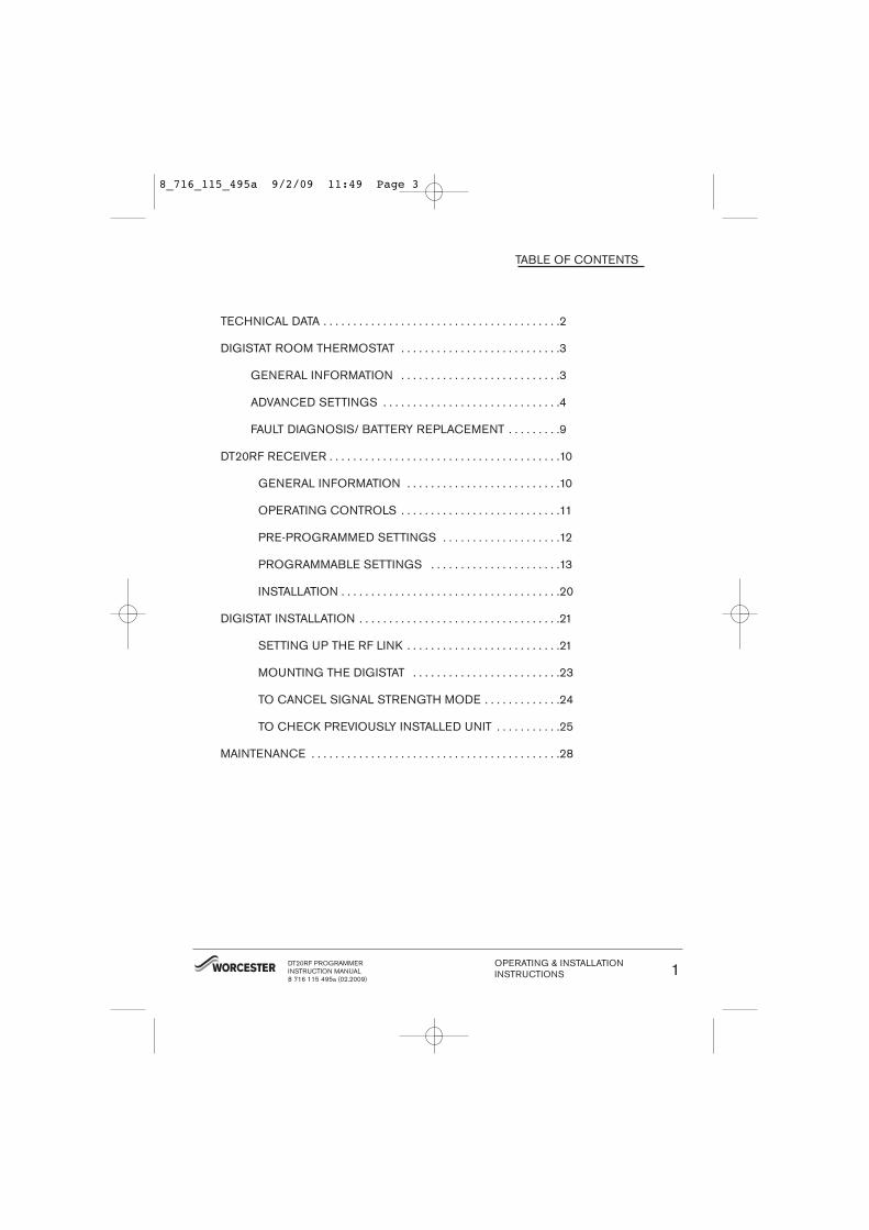
TABLE OF CONTENTS
TECHNICAL DATA . . . . . . . . . . . . . . . . . . . . . . . . . . . . . . . . . . . . . . . .2
DIGISTAT ROOM THERMOSTAT . . . . . . . . . . . . . . . . . . . . . . . . . . .3
GENERAL INFORMATION . . . . . . . . . . . . . . . . . . . . . . . . . . .3
ADVANCED SETTINGS . . . . . . . . . . . . . . . . . . . . . . . . . . . . . .4
FAULT DIAGNOSIS/ BATTERY REPLACEMENT . . . . . . . . .9
DT20RF RECEIVER . . . . . . . . . . . . . . . . . . . . . . . . . . . . . . . . . . . . . . .10
GENERAL INFORMATION . . . . . . . . . . . . . . . . . . . . . . . . . .10
OPERATING CONTROLS . . . . . . . . . . . . . . . . . . . . . . . . . . .11
PRE-PROGRAMMED SETTINGS . . . . . . . . . . . . . . . . . . . .12
PROGRAMMABLE SETTINGS . . . . . . . . . . . . . . . . . . . . . .13
INSTALLATION . . . . . . . . . . . . . . . . . . . . . . . . . . . . . . . . . . . . .20
DIGISTAT INSTALLATION . . . . . . . . . . . . . . . . . . . . . . . . . . . . . . . . . .21
SETTING UP THE RF LINK . . . . . . . . . . . . . . . . . . . . . . . . . .21
MOUNTING THE DIGISTAT . . . . . . . . . . . . . . . . . . . . . . . . .23
TO CANCEL SIGNAL STRENGTH MODE . . . . . . . . . . . . .24
TO CHECK PREVIOUSLY INSTALLED UNIT . . . . . . . . . . .25
MAINTENANCE . . . . . . . . . . . . . . . . . . . . . . . . . . . . . . . . . . . . . . . . . .28
DT20RF PROGRAMMERINSTRUCTION MANUAL8 716 115 495a (02.2009)
OPERATING & INSTALLATIONINSTRUCTIONS 1
8_716_115_495a 9/2/09 11:49 Page 3
EC Directives:European Union Law Directive 2000/84/ECLow Voltage Directive (2006/95/EC)Electro-Magnetic Compatibility Directive (89/336/EEC)EC Marking Directive (93/68/EEC)
STANDARD PACKAGE:Programmable / RF receiverRemote RF transmitterScrews (x2)Wall Plugs (x2)InstructionsBatteries (x2) AA Alkaline
TECHNICAL DATA
DIGISTAT TRANSMITTERROOM THERMOSTAT
DT20RF RECEIVER
Power supply 2xAA 1.5V alkaline batteries 24Vd.c. less than 65mA
Radio frequency 433 MHz 433 MHz
Radio signal range The range may be affected by the composition / density andnumber of walls between the Digistat RF and receiver.
30 metres typically, through two internal plasterboard walls and a ceiling.26 metres typically, through three internal plasterboard walls and a ceiling.17 metres typically, through two internal plasterboard walls a ceiling andone external cavity wall.
These distances are provided for guidance only, many factors can affectthe range of the transmitter, including metal pipework, appliances andeven furniture.
Temperature setting range 5°C to 30°C 5°C to 30°C
Control Accuracy: + 0.5°C @ 20°C better than ±1 second per day @ 25°C
Ambient Temperature:Operating
0°C to 50°C 0 to 50°C
Ambient Temperature: Storage
–20°C to 55°C --
Humidity operating range -- 30 - 95 % non condensing up to 45°C
Mounting: Suitable for surface mounting
RF: No wiring required
DHW & CH ON/OFF periods -- 3 ON / 3 OFF
DHW & CH programs 7 days
Class of protection /Degree of protection
IP30 IP24
Battery back up time & date - - 10 years minimum
Shortest switching period - - 1 minute
OPERATING & INSTALLATIONINSTRUCTIONS2 DT20RF PROGRAMMER
INSTRUCTION MANUAL8 716 115 495a (02.2009)
8_716_115_495a 9/2/09 11:49 Page 4

What is a room thermostat?
A room thermostat simply switches the heatingsystem on and off as necessary. It works by sens-ing the air temperature, switching on the heatingwhen the air temperature falls below the thermo-stat setting, and switching it off once this settemperature has been reached.
Turning a room thermostat to a higher setting willnot make the room heat up any faster. Howquickly the room heats up depends on the designof the heating system, for example, the size ofboiler and radiators.
Neither does the setting affect how quickly theroom cools down. Turning a room thermostat to alower setting will result in the room being con-trolled at a lower temperature, and saves energy.
The heating system will not work if a time switchor programmer has switched it off.
The way to set and use your room thermostat isto find the lowest temperature setting that youare comfortable with, and then leave it alone todo its job. The best way to do this is to set theroom thermostat to a low temperature, at say18°C and then turn it up by one degree each dayuntil you are comfortable with the temperature.You won’t have to adjust the thermostat further.Any adjustment above this setting may wasteenergy.
If your heating system is a boiler with radiators,there will usually be only one room thermostat tocontrol the whole house. But you can have differ-ent temperatures in individual rooms by installingthermostatic radiator valves (TRVs) on individualradiators. If you don’t have TRVs, you shouldchoose a temperature that is reasonable for thewhole house. If you do have TRVs, you canchoose a slightly higher setting to make sure thateven the coldest room is comfortable, then pre-vent any overheating in other rooms by adjustingthe TRVs.
Room thermostats need a free flow of air tosense the temperature, so they must not be cov-ered by curtains or blocked by furniture. Nearbyfires, televisions, wall or table lamps may preventthe thermostat from working properly.
LCD Display
Dial
Set button Battery Compartment
SET
ºc
Heat demand is shown by a flame symbol, i.e. the thermostat is calling for heat to bring the room up to or maintain the desired temperature.
During normal operation the display shows the actual room temperature.
When the desired temperature is being adjusted 'SET' is shown.
Low battery warning shown by flashing symbol.
An RF Model is shown by an antenna symbol on the display.
FEATURES
The Digistat RF room thermostat has the followinguser settings:• Required room temperature (temperature set-
point)• Preset temperature setting - Advanced feature• Minimum & Maximum temperature settings -
Advanced feature
Simple Setting or Operating
To set the required room temperature
• The display normally shows the current roomtemperature to within 0.5°C
• To adjust the required temperature, turn thedial clockwise to increase or anti-clockwise to decrease, (1 click = 1°C), the LCD will displaythe temperature setpoint as it is being adjustedand ‘SET’ will be displayed. After a few secondsthe display will return to normal operation andwill display the actual room temperature.
While adjusting the temperature during normaloperation, when you reach the maximum orminimum possible setting the display will flash toindicate you cannot adjust the product further.
DIGISTAT ROOM THERMOSTATGENERAL INFORMATION
DT20RF PROGRAMMERINSTRUCTION MANUAL8 716 115 495a (02.2009)
OPERATING & INSTALLATIONINSTRUCTIONS 3
8_716_115_495a 9/2/09 11:49 Page 5
ADVANCED FEATURES
Adjusting the Setpoint using the Preset
Temperature Mode
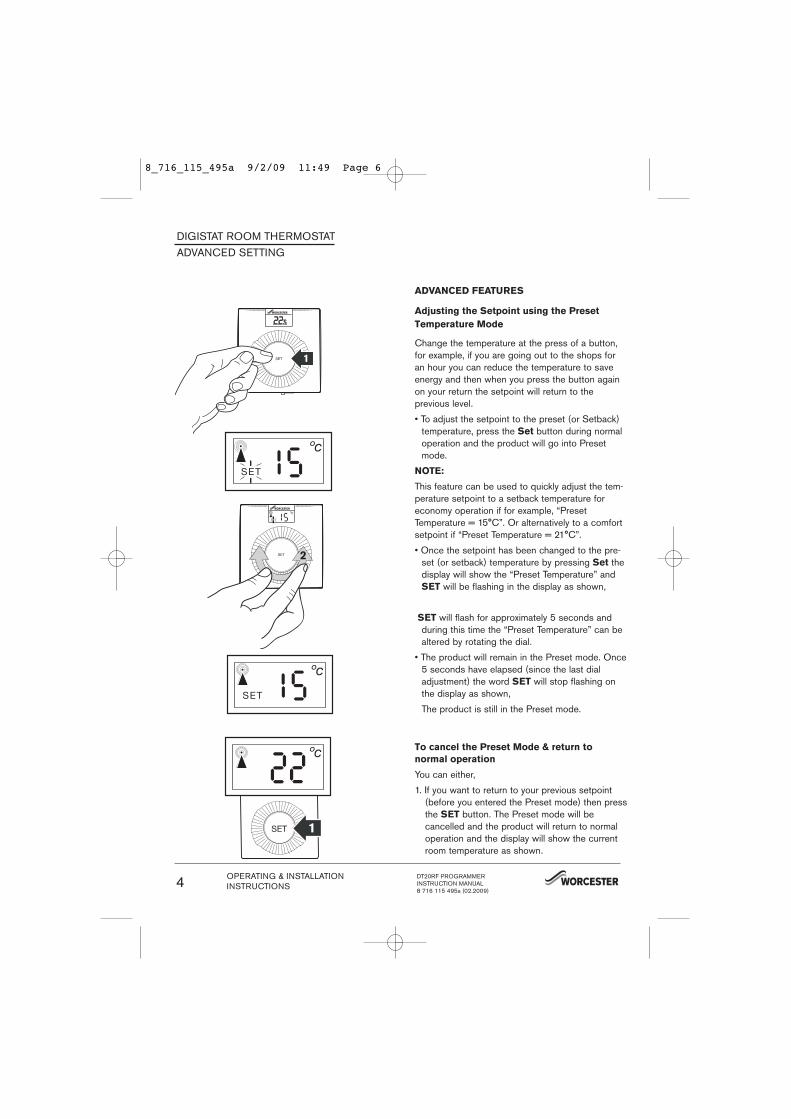
Change the temperature at the press of a button,for example, if you are going out to the shops foran hour you can reduce the temperature to saveenergy and then when you press the button againon your return the setpoint will return to theprevious level.
• To adjust the setpoint to the preset (or Setback)temperature, press the Set button during normaloperation and the product will go into Presetmode.
NOTE:
This feature can be used to quickly adjust the tem-perature setpoint to a setback temperature foreconomy operation if for example, “PresetTemperature = 15°C”. Or alternatively to a comfortsetpoint if “Preset Temperature = 21°C”.
• Once the setpoint has been changed to the pre-set (or setback) temperature by pressing Set thedisplay will show the “Preset Temperature” andSET will be flashing in the display as shown,
SET will flash for approximately 5 seconds andduring this time the “Preset Temperature” can bealtered by rotating the dial.
• The product will remain in the Preset mode. Once5 seconds have elapsed (since the last dialadjustment) the word SET will stop flashing onthe display as shown,
The product is still in the Preset mode.
To cancel the Preset Mode & return to
normal operation
You can either,
1. If you want to return to your previous setpoint(before you entered the Preset mode) then pressthe SET button. The Preset mode will becancelled and the product will return to normaloperation and the display will show the currentroom temperature as shown.
ºc
SET
ºc
SET
ºc
DIGISTAT ROOM THERMOSTATADVANCED SETTING
OPERATING & INSTALLATIONINSTRUCTIONS4 DT20RF PROGRAMMER
INSTRUCTION MANUAL8 716 115 495a (02.2009)
8_716_115_495a 9/2/09 11:49 Page 6
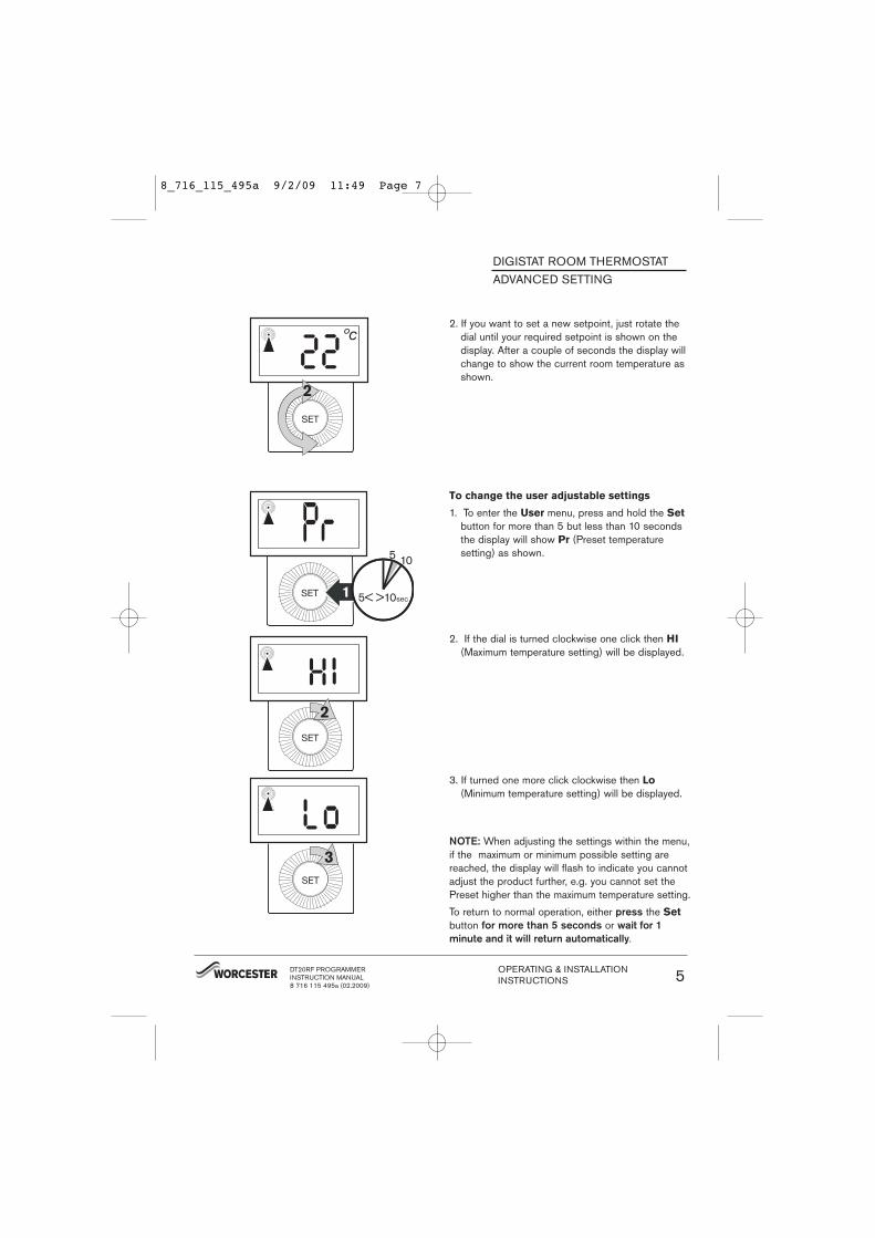
2. If you want to set a new setpoint, just rotate thedial until your required setpoint is shown on thedisplay. After a couple of seconds the display willchange to show the current room temperature asshown.
To change the user adjustable settings
1. To enter the User menu, press and hold the Set
button for more than 5 but less than 10 secondsthe display will show Pr (Preset temperature setting) as shown.
2. If the dial is turned clockwise one click then HI
(Maximum temperature setting) will be displayed.
3. If turned one more click clockwise then Lo
(Minimum temperature setting) will be displayed.
NOTE: When adjusting the settings within the menu,if the maximum or minimum possible setting arereached, the display will flash to indicate you cannotadjust the product further, e.g. you cannot set thePreset higher than the maximum temperature setting.
To return to normal operation, either press the Set
button for more than 5 seconds or wait for 1
minute and it will return automatically.
ºc
2
DIGISTAT ROOM THERMOSTATADVANCED SETTING
DT20RF PROGRAMMERINSTRUCTION MANUAL8 716 115 495a (02.2009)
OPERATING & INSTALLATIONINSTRUCTIONS 5
8_716_115_495a 9/2/09 11:49 Page 7
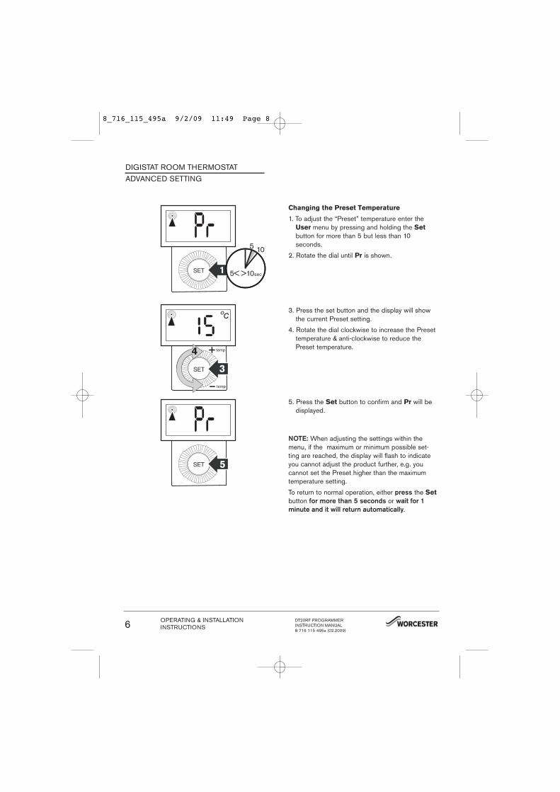
Changing the Preset Temperature
1. To adjust the “Preset” temperature enter theUser menu by pressing and holding the Set
button for more than 5 but less than 10seconds.
2. Rotate the dial until Pr is shown.
3. Press the set button and the display will showthe current Preset setting.
4. Rotate the dial clockwise to increase the Presettemperature & anti-clockwise to reduce thePreset temperature.
5. Press the Set button to confirm and Pr will bedisplayed.
NOTE: When adjusting the settings within themenu, if the maximum or minimum possible set-ting are reached, the display will flash to indicateyou cannot adjust the product further, e.g. youcannot set the Preset higher than the maximumtemperature setting.
To return to normal operation, either press the Set
button for more than 5 seconds or wait for 1
minute and it will return automatically.
DIGISTAT ROOM THERMOSTATADVANCED SETTING
OPERATING & INSTALLATIONINSTRUCTIONS6 DT20RF PROGRAMMER
INSTRUCTION MANUAL8 716 115 495a (02.2009)
8_716_115_495a 9/2/09 11:49 Page 8
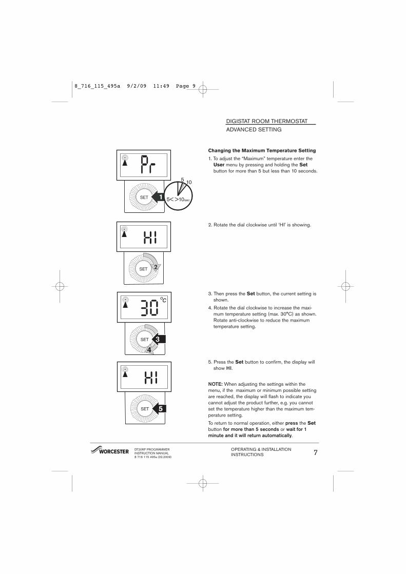
Changing the Maximum Temperature Setting
1. To adjust the “Maximum” temperature enter theUser menu by pressing and holding the Set
button for more than 5 but less than 10 seconds.
2. Rotate the dial clockwise until ‘HI’ is showing.
3. Then press the Set button, the current setting isshown.
4. Rotate the dial clockwise to increase the maxi-mum temperature setting (max. 30°C) as shown.Rotate anti-clockwise to reduce the maximumtemperature setting.
5. Press the Set button to confirm, the display willshow HI.
NOTE: When adjusting the settings within themenu, if the maximum or minimum possible settingare reached, the display will flash to indicate youcannot adjust the product further, e.g. you cannotset the temperature higher than the maximum tem-perature setting.
To return to normal operation, either press the Set
button for more than 5 seconds or wait for 1
minute and it will return automatically.
DIGISTAT ROOM THERMOSTATADVANCED SETTING
2
DT20RF PROGRAMMERINSTRUCTION MANUAL8 716 115 495a (02.2009)
OPERATING & INSTALLATIONINSTRUCTIONS 7
8_716_115_495a 9/2/09 11:49 Page 9

Changing the Minimum Temperature Setting
1. To adjust the “Preset” temperature enter the User
menu by pressing and holding the Set button formore than 5 but less than 10 seconds.
2. Rotate the dial clockwise until Lo Is showing.
3. Then press the Set button, the current setting isshown.
4. Rotate the dial clockwise to increase the mini-mum temperature setting and anti-clockwise toreduce the minimum temperature setting (min.5°C) as shown.
5. Press the Set button to confirm, the display willshow Lo.
NOTE: When adjusting the settings within themenu, if the maximum or minimum possible settingare reached, the display will flash to indicate youcannot adjust the product further, e.g. you cannotset the temperature lower than the minimum temperature setting.
To return to normal operation, either press the Set
button for more than 5 seconds or wait for 1
minute and it will return automatically.
DIGISTAT ROOM THERMOSTATADVANCED SETTING
OPERATING & INSTALLATIONINSTRUCTIONS8 DT20RF PROGRAMMER
INSTRUCTION MANUAL8 716 115 495a (02.2009)
8_716_115_495a 9/2/09 11:49 Page 10
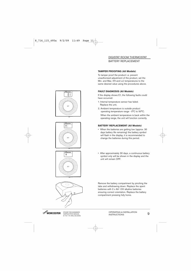
TAMPER PROOFING (All Models)
To tamper proof the product i.e. preventunauthorised adjustment of the product, set theMin. and Max. (HI and Lo) temperatures to thesame desired value using the procedures above.
FAULT DIAGNOSIS (All Models)
If the display shows E1, the following faults couldhave occurred:
1. Internal temperature sensor has failed. Replace the unit,
2. Ambient temperature is outside product operating temperature range - 0°C to 50°C.
When the ambient temperature is back within theoperating range, the unit will function correctly.
BATTERY REPLACEMENT (All Models)
• When the batteries are getting low (approx. 30days battery life remaining) the battery symbolwill flash in the display, it is recommended tochange the batteries during this period.
• After approximately 30 days, a continuous battery symbol only will be shown in the display and theunit will remain OFF.
Remove the battery compartment by pinching thetabs and withdrawing down. Replace the spent batteries with 2 x AA 1.5V alkaline batteriesensuring correct orientation. Replace the batterycompartment pressing fully home.
DIGISTAT ROOM THERMOSTATBATTERY REPLACEMENT
DT20RF PROGRAMMERINSTRUCTION MANUAL8 716 115 495a (02.2009)
OPERATING & INSTALLATIONINSTRUCTIONS 9
8_716_115_495a 9/2/09 11:49 Page 11
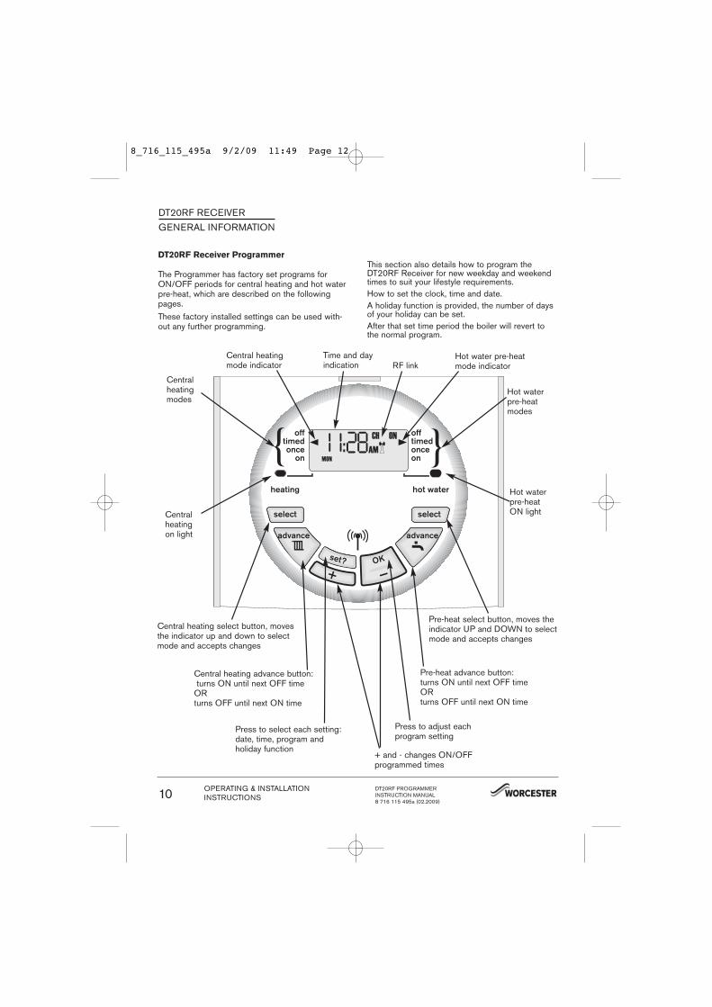
Central heatingon light
Central heating select button, movesthe indicator up and down to selectmode and accepts changes
Central heating advance button:turns ON until next OFF time
ORturns OFF until next ON time
Press to adjust each program setting
Pre-heat select button, moves theindicator UP and DOWN to selectmode and accepts changes
Pre-heat advance button:turns ON until next OFF timeORturns OFF until next ON time
Hot water pre-heatmode indicator
Central heatingmode indicator
+ and - changes ON/OFF programmed times
Press to select each setting: date, time, program and holiday function
Hot waterpre-heatmodes
Centralheatingmodes
DT20RF RECEIVERGENERAL INFORMATION
Time and dayindication
}{
DT20RF Receiver Programmer
The Programmer has factory set programs forON/OFF periods for central heating and hot waterpre-heat, which are described on the followingpages. These factory installed settings can be used with-out any further programming.
This section also details how to program the DT20RF Receiver for new weekday and weekendtimes to suit your lifestyle requirements.How to set the clock, time and date.A holiday function is provided, the number of daysof your holiday can be set.After that set time period the boiler will revert tothe normal program.
Hot waterpre-heatON light
RF link
OPERATING & INSTALLATIONINSTRUCTIONS
DT20RF PROGRAMMERINSTRUCTION MANUAL8 716 115 495a (02.2009)
10
8_716_115_495a 9/2/09 11:49 Page 12
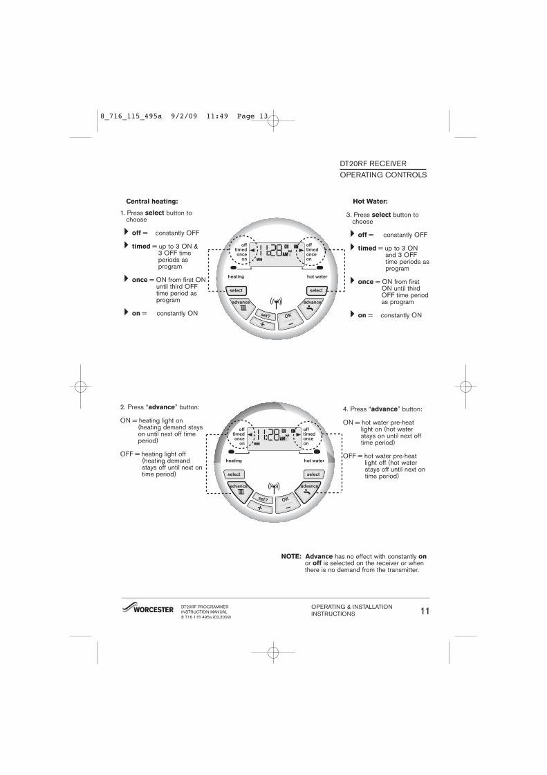
Central heating:
1. Press select button tochoose
�off = constantly OFF
�timed = up to 3 ON & 3 OFF time periods as program
�once = ON from first ONuntil third OFFtime period asprogram
�on = constantly ON
2. Press “advance” button:
ON = heating light on (heating demand stayson until next off timeperiod)
OFF = heating light off(heating demandstays off until next ontime period)
DT20RF RECEIVEROPERATING CONTROLS
Hot Water:
3. Press select button tochoose
�off = constantly OFF
�timed = up to 3 ONand 3 OFFtime periods asprogram
�once = ON from firstON until thirdOFF time periodas program
�on = constantly ON
4. Press “advance” button:
ON = hot water pre-heatlight on (hot waterstays on until next offtime period)
OFF = hot water pre-heatlight off (hot waterstays off until next ontime period)
NOTE: Advance has no effect with constantly onor off is selected on the receiver or whenthere is no demand from the transmitter.
DT20RF PROGRAMMERINSTRUCTION MANUAL8 716 115 495a (02.2009)
OPERATING & INSTALLATIONINSTRUCTIONS 11
8_716_115_495a 9/2/09 11:49 Page 13
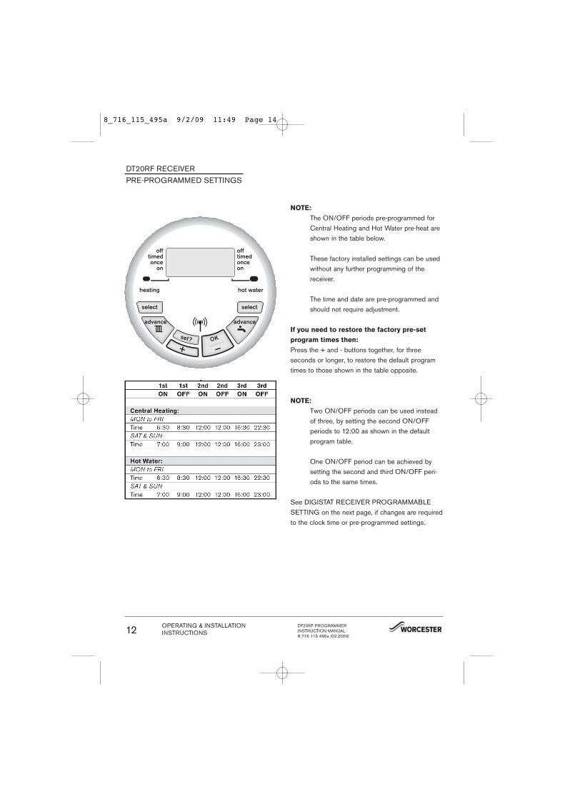
NOTE:
The ON/OFF periods pre-programmed forCentral Heating and Hot Water pre-heat areshown in the table below.
These factory installed settings can be usedwithout any further programming of thereceiver.
The time and date are pre-programmed andshould not require adjustment.
If you need to restore the factory pre-set
program times then:
Press the + and - buttons together, for three seconds or longer, to restore the default programtimes to those shown in the table opposite.
NOTE:
Two ON/OFF periods can be used insteadof three, by setting the second ON/OFFperiods to 12:00 as shown in the defaultprogram table.
One ON/OFF period can be achieved bysetting the second and third ON/OFF peri-ods to the same times.
See DIGISTAT RECEIVER PROGRAMMABLESETTING on the next page, if changes are requiredto the clock time or pre-programmed settings.
DT20RF RECEIVERPRE-PROGRAMMED SETTINGS
OPERATING & INSTALLATIONINSTRUCTIONS
DT20RF PROGRAMMERINSTRUCTION MANUAL8 716 115 495a (02.2009)
12
8_716_115_495a 9/2/09 11:49 Page 14
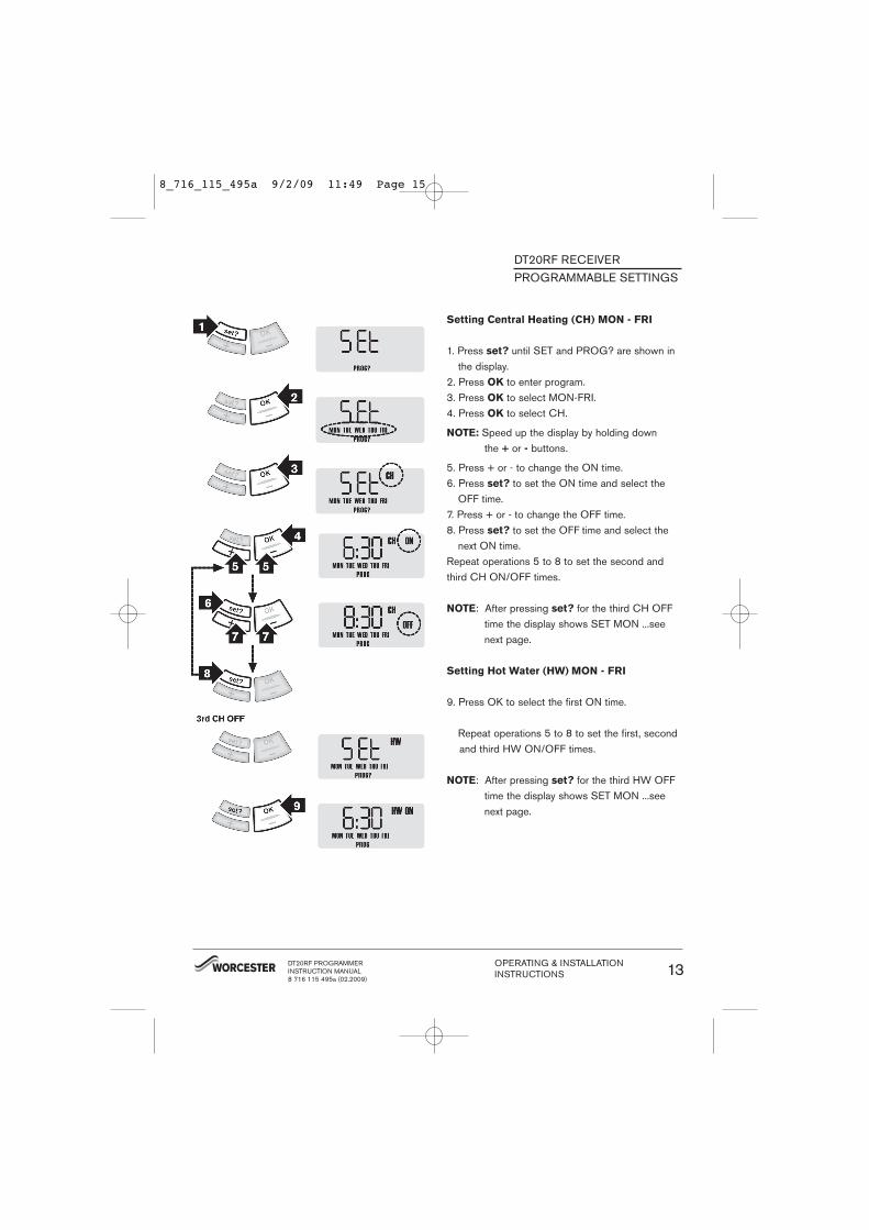
Setting Central Heating (CH) MON - FRI
1. Press set? until SET and PROG? are shown inthe display.
2. Press OK to enter program.3. Press OK to select MON-FRI.4. Press OK to select CH.
NOTE: Speed up the display by holding down the + or - buttons.
5. Press + or - to change the ON time.6. Press set? to set the ON time and select the
OFF time.7. Press + or - to change the OFF time.8. Press set? to set the OFF time and select the
next ON time.Repeat operations 5 to 8 to set the second andthird CH ON/OFF times.
NOTE: After pressing set? for the third CH OFFtime the display shows SET MON ...seenext page.
Setting Hot Water (HW) MON - FRI
9. Press OK to select the first ON time.
Repeat operations 5 to 8 to set the first, secondand third HW ON/OFF times.
NOTE: After pressing set? for the third HW OFFtime the display shows SET MON ...seenext page.
DT20RF RECEIVERPROGRAMMABLE SETTINGS
DT20RF PROGRAMMERINSTRUCTION MANUAL8 716 115 495a (02.2009)
OPERATING & INSTALLATIONINSTRUCTIONS 13
8_716_115_495a 9/2/09 11:49 Page 15
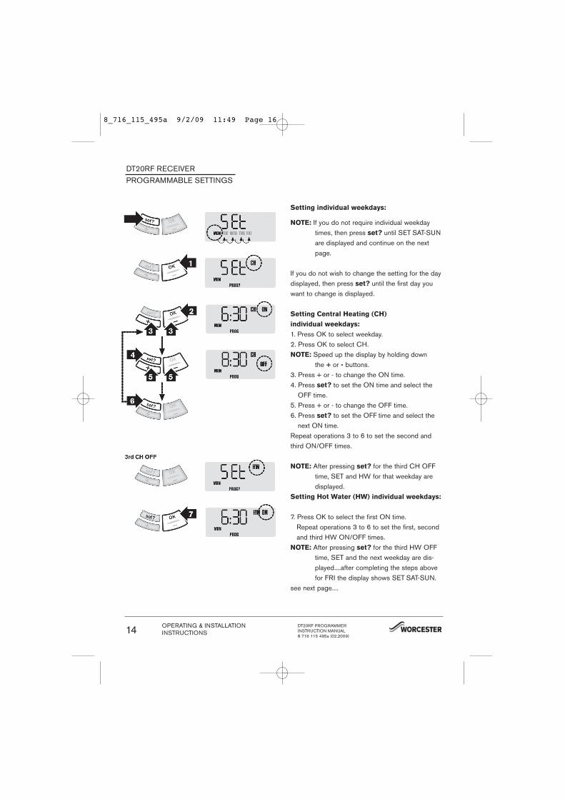
Setting individual weekdays:
NOTE: If you do not require individual weekdaytimes, then press set? until SET SAT-SUNare displayed and continue on the nextpage.
If you do not wish to change the setting for the daydisplayed, then press set? until the first day youwant to change is displayed.
Setting Central Heating (CH)
individual weekdays:
1. Press OK to select weekday.2. Press OK to select CH.NOTE: Speed up the display by holding down
the + or - buttons.3. Press + or - to change the ON time.4. Press set? to set the ON time and select the
OFF time.5. Press + or - to change the OFF time.6. Press set? to set the OFF time and select the
next ON time.Repeat operations 3 to 6 to set the second andthird ON/OFF times.
NOTE: After pressing set? for the third CH OFFtime, SET and HW for that weekday aredisplayed.
Setting Hot Water (HW) individual weekdays:
7. Press OK to select the first ON time.Repeat operations 3 to 6 to set the first, secondand third HW ON/OFF times.
NOTE: After pressing set? for the third HW OFFtime, SET and the next weekday are dis-played....after completing the steps abovefor FRI the display shows SET SAT-SUN.
see next page....
DT20RF RECEIVERPROGRAMMABLE SETTINGS
OPERATING & INSTALLATIONINSTRUCTIONS
DT20RF PROGRAMMERINSTRUCTION MANUAL8 716 115 495a (02.2009)
14
8_716_115_495a 9/2/09 11:49 Page 16
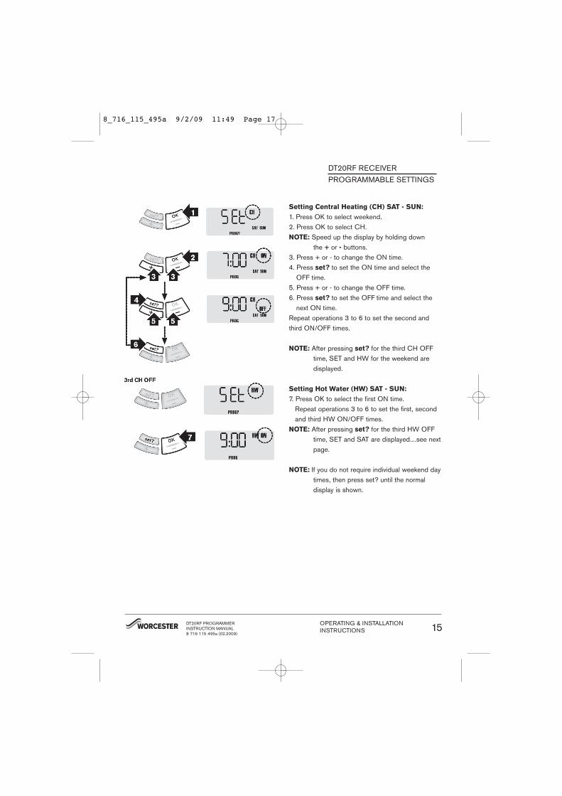
Setting Central Heating (CH) SAT - SUN:
1. Press OK to select weekend.2. Press OK to select CH.NOTE: Speed up the display by holding down
the + or - buttons.3. Press + or - to change the ON time.4. Press set? to set the ON time and select the
OFF time.5. Press + or - to change the OFF time.6. Press set? to set the OFF time and select the
next ON time.Repeat operations 3 to 6 to set the second andthird ON/OFF times.
NOTE: After pressing set? for the third CH OFFtime, SET and HW for the weekend aredisplayed.
Setting Hot Water (HW) SAT - SUN:
7. Press OK to select the first ON time.Repeat operations 3 to 6 to set the first, secondand third HW ON/OFF times.
NOTE: After pressing set? for the third HW OFFtime, SET and SAT are displayed....see nextpage.
NOTE: If you do not require individual weekend daytimes, then press set? until the normal display is shown.
DT20RF RECEIVERPROGRAMMABLE SETTINGS
DT20RF PROGRAMMERINSTRUCTION MANUAL8 716 115 495a (02.2009)
OPERATING & INSTALLATIONINSTRUCTIONS 15
8_716_115_495a 9/2/09 11:49 Page 17
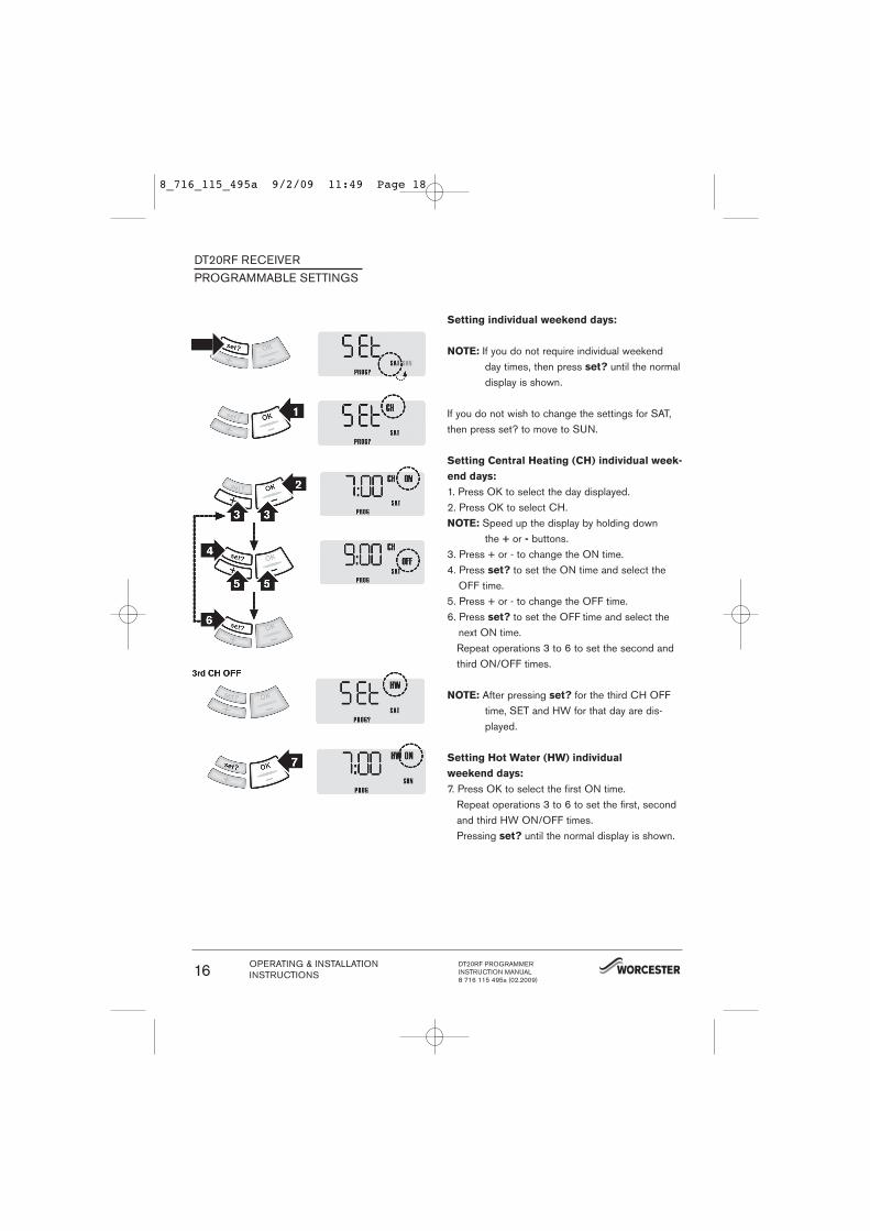
Setting individual weekend days:
NOTE: If you do not require individual weekend day times, then press set? until the normaldisplay is shown.
If you do not wish to change the settings for SAT,then press set? to move to SUN.
Setting Central Heating (CH) individual week-
end days:
1. Press OK to select the day displayed.2. Press OK to select CH.NOTE: Speed up the display by holding down
the + or - buttons.3. Press + or - to change the ON time.4. Press set? to set the ON time and select the
OFF time.5. Press + or - to change the OFF time.6. Press set? to set the OFF time and select the
next ON time.Repeat operations 3 to 6 to set the second andthird ON/OFF times.
NOTE: After pressing set? for the third CH OFFtime, SET and HW for that day are dis-played.
Setting Hot Water (HW) individual
weekend days:
7. Press OK to select the first ON time.Repeat operations 3 to 6 to set the first, secondand third HW ON/OFF times.Pressing set? until the normal display is shown.
DT20RF RECEIVERPROGRAMMABLE SETTINGS
OPERATING & INSTALLATIONINSTRUCTIONS
DT20RF PROGRAMMERINSTRUCTION MANUAL8 716 115 495a (02.2009)
16
8_716_115_495a 9/2/09 11:49 Page 18
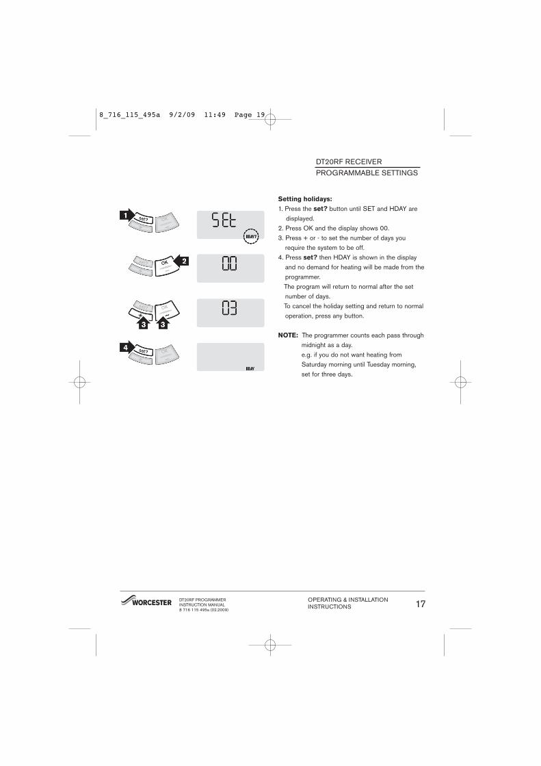
Setting holidays:
1. Press the set? button until SET and HDAY aredisplayed.
2. Press OK and the display shows 00.3. Press + or - to set the number of days you
require the system to be off.4. Press set? then HDAY is shown in the display
and no demand for heating will be made from theprogrammer.The program will return to normal after the setnumber of days.To cancel the holiday setting and return to normaloperation, press any button.
NOTE: The programmer counts each pass throughmidnight as a day.e.g. if you do not want heating fromSaturday morning until Tuesday morning,set for three days.
DT20RF RECEIVERPROGRAMMABLE SETTINGS
DT20RF PROGRAMMERINSTRUCTION MANUAL8 716 115 495a (02.2009)
OPERATING & INSTALLATIONINSTRUCTIONS 17
8_716_115_495a 9/2/09 11:49 Page 19
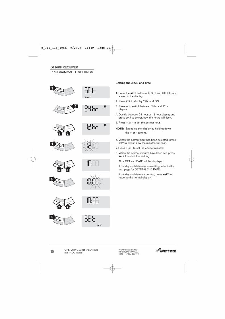
Setting the clock and time
1. Press the set? button until SET and CLOCK areshown in the display.
2. Press OK to display 24hr and ON.
3. Press + to switch between 24hr and 12hr display.
4. Decide between 24 hour or 12 hour display andpress set? to select, now the hours will flash.
5. Press + or - to set the correct hour.
NOTE: Speed up the display by holding downthe + or - buttons.
6. When the correct hour has been selected, pressset? to select, now the minutes will flash.
7. Press + or - to set the correct minutes.
8. When the correct minutes have been set, pressset? to select that setting.
Now SET and DATE will be displayed.
If the day and date needs resetting, refer to thenext page for SETTING THE DATE.
If the day and date are correct, press set? toreturn to the normal display.
DT20RF RECEIVERPROGRAMMABLE SETTINGS
OPERATING & INSTALLATIONINSTRUCTIONS
DT20RF PROGRAMMERINSTRUCTION MANUAL8 716 115 495a (02.2009)
18
8_716_115_495a 9/2/09 11:49 Page 20

Setting the date:
1. Press the set? button until SET and DATE? aredisplayed.
2. Press the OK button once, the year flashes onthe display.
3. Press + or - to set the correct year, e.g. 07.
4. When the correct year has been chosen, pressset? to select, now the month will flash.
5. Press + or - to select the correct month, e.g. 08.
6. When the correct month has been chosen, pressset? to select, now the day will flash.
7. Press + or - to select the correct day, e.g. 16.
8. When the correct day has been chosen, pressset? to select, now dLS will be displayed andON will flash.
9. Press + or - to switch between ON or OFF.If you choose ON then the clock will automatical-ly adjust the time for Daylight saving. If youchoose OFF then the time will not change totake account of the Daylight Saving time changetwice a year.
10. Press set? twice to return to the normal display.
NOTE: dLS = Day Light Savings time
DT20RF RECEIVERPROGRAMMABLE SETTINGS
DT20RF PROGRAMMERINSTRUCTION MANUAL8 716 115 495a (02.2009)
OPERATING & INSTALLATIONINSTRUCTIONS 19
8_716_115_495a 9/2/09 11:49 Page 21
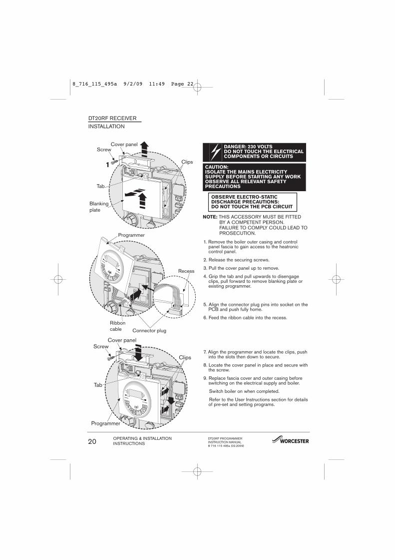
Clips
Cover panelScrew
Tab
Blanking plate
Tab
Cover panel
Clips
Screw
Programmer
DANGER: 230 VOLTSDO NOT TOUCH THE ELECTRICALCOMPONENTS OR CIRCUITS
CAUTION: ISOLATE THE MAINS ELECTRICITY SUPPLY BEFORE STARTING ANY WORKOBSERVE ALL RELEVANT SAFETY PRECAUTIONS
OBSERVE ELECTRO-STATIC DISCHARGE PRECAUTIONS:DO NOT TOUCH THE PCB CIRCUIT
5. Align the connector plug pins into socket on thePCB and push fully home.
6. Feed the ribbon cable into the recess.
7. Align the programmer and locate the clips, pushinto the slots then down to secure.
8. Locate the cover panel in place and secure withthe screw.
9. Replace fascia cover and outer casing beforeswitching on the electrical supply and boiler.
Switch boiler on when completed.
Refer to the User Instructions section for detailsof pre-set and setting programs.
DT20RF RECEIVERINSTALLATION
1. Remove the boiler outer casing and controlpanel fascia to gain access to the heatronic control panel.
2. Release the securing screws.
3. Pull the cover panel up to remove.
4. Grip the tab and pull upwards to disengageclips, pull forward to remove blanking plate orexisting programmer.
Recess
Programmer
Ribboncable Connector plug
NOTE: THIS ACCESSORY MUST BE FITTED BY A COMPETENT PERSON. FAILURE TO COMPLY COULD LEAD TO PROSECUTION.
OPERATING & INSTALLATIONINSTRUCTIONS
DT20RF PROGRAMMERINSTRUCTION MANUAL8 716 115 495a (02.2009)
20
8_716_115_495a 9/2/09 11:49 Page 22

DIGISTAT / DT20RF RECEIVERSETTING UP THE RF LINK
DIGISTATINSTALLATION
Receiver set up:
After initial start up, the colon, CH and antenna symbols should be flashing on the display.
1. Press the set? button 4 times
2. Press the OK button once
3. Press the set? button 4 times; Lrn and OFFshould be displayed
4. Press the + button so the display shows ON anda flashing antenna symbol. The learn mode is nowready to receive a signal from the transmitterduring the next two minutes.
Transmitter set up:
1. Take the Digistat Programmer unit and stand nearthe boiler.
2. Remove the battery cover and fit the batteries.
How to fit the batteries
Remove the battery compartment by pinching thetabs and withdrawing down. Replace the spent batteries with 2 x AA 1.5V alkaline batteries ensuringcorrect orientation. Replace the battery compartmentpressing fully home.
3. The symbols on the receiver will stop flashing andthe display will show ‘SSI, Antenna and ON’.
4. Press ‘SET’ on the receiver and the display willshow ‘SSI and Antenna’.
5. After a few seconds the display will show ‘- - -’.
Transmitter battery compartment
DT20RF PROGRAMMERINSTRUCTION MANUAL8 716 115 495a (02.2009)
OPERATING & INSTALLATIONINSTRUCTIONS 21
8_716_115_495a 9/2/09 11:49 Page 23
DIGISTATINSTALLATION
DIGISTAT / DT20RF RECEIVER
SETTING UP THE RF LINK
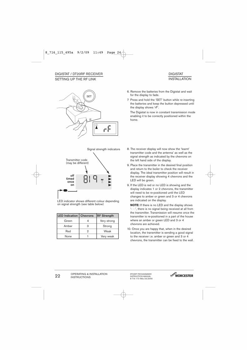
6. Remove the batteries from the Digistat and waitfor the display to fade.
7 Press and hold the ‘SET’ button while re-insertingthe batteries and keep the button depressed untilthe display shows ‘rF’.
The Digistat is now in constant transmission modeenabling it to be correctly positioned within thehome.
8. The receiver display will now show the ‘learnt’transmitter code and the antenna’ as well as thesignal strength as indicated by the chevrons onthe left hand side of the display.
9. Place the transmitter in the desired final positionand return to the boiler to check the receiverdisplay. The ideal transmitter position will result inthe receiver display showing 4 chevrons and theLED will be green.
9. If the LED is red or no LED is showing and thedisplay indicates 1 or 2 chevrons, the transmitterwill need to be re-positioned until the LEDchanges to amber or green and 3 or 4 chevronsare indicated on the display.
NOTE: If there is no LED and the display shows‘- - -’, there is no signal being received at all fromthe transmitter. Transmission will resume once thetransmitter is re-positioned in a part of the housewhere an amber or green LED and 3 or 4chevrons are achieved.
10. Once you are happy that, when in the desiredlocation, the transmitter is sending a good signalto the receiver i.e. amber or green and 3 or 4chevrons, the transmitter can be fixed to the wall.
Signal strength indicators
Transmitter code(may be different)
LED indicator shows different colour dependingon signal strength (see table below)
LED Indication Chevrons RF Strength
Green
Amber
Red
None
4
3
2
1
Very strong
Strong
Weak
Very weak
OPERATING & INSTALLATIONINSTRUCTIONS
DT20RF PROGRAMMERINSTRUCTION MANUAL8 716 115 495a (02.2009)
22
8_716_115_495a 9/2/09 11:49 Page 24
DIGISTATINSTALLATION
DIGISTAT / DT20RF RECEIVERMOUNTING THE DIGISTAT
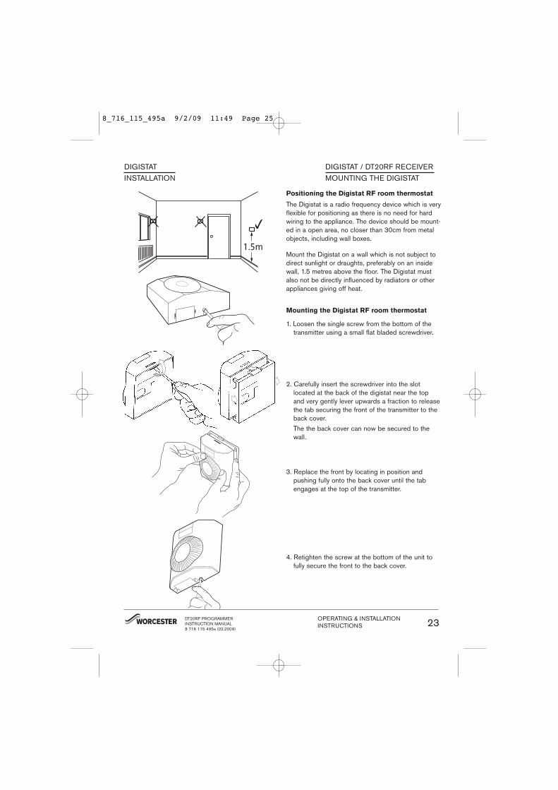
1. Loosen the single screw from the bottom of thetransmitter using a small flat bladed screwdriver.
2. Carefully insert the screwdriver into the slotlocated at the back of the digistat near the topand very gently lever upwards a fraction to releasethe tab securing the front of the transmitter to theback cover.The the back cover can now be secured to thewall.
Mounting the Digistat RF room thermostat
3. Replace the front by locating in position andpushing fully onto the back cover until the tabengages at the top of the transmitter.
4. Retighten the screw at the bottom of the unit tofully secure the front to the back cover.
DT20RF PROGRAMMERINSTRUCTION MANUAL8 716 115 495a (02.2009)
OPERATING & INSTALLATIONINSTRUCTIONS 23
Positioning the Digistat RF room thermostat
The Digistat is a radio frequency device which is veryflexible for positioning as there is no need for hardwiring to the appliance. The device should be mount-ed in a open area, no closer than 30cm from metalobjects, including wall boxes.
Mount the Digistat on a wall which is not subject todirect sunlight or draughts, preferably on an insidewall, 1.5 metres above the floor. The Digistat mustalso not be directly influenced by radiators or otherappliances giving off heat.
8_716_115_495a 9/2/09 11:49 Page 25
DIGISTATINSTALLATION
DIGISTAT / DT20RF RECEIVER
TO CANCEL SIGNALSTRENGTH MODE
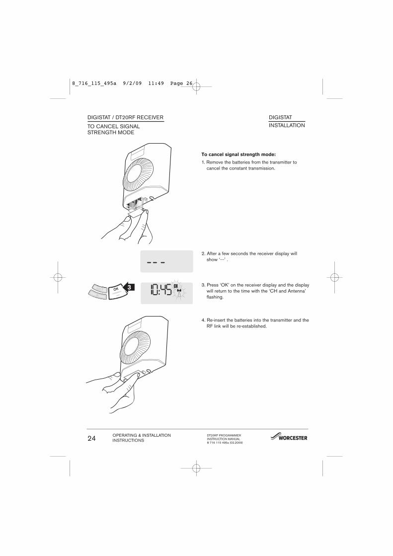
To cancel signal strength mode:
1. Remove the batteries from the transmitter tocancel the constant transmission.
2. After a few seconds the receiver display willshow ‘---’ .
3. Press ‘OK’ on the receiver display and the displaywill return to the time with the ‘CH and Antenna’flashing.
4. Re-insert the batteries into the transmitter and theRF link will be re-established.
OPERATING & INSTALLATIONINSTRUCTIONS
DT20RF PROGRAMMERINSTRUCTION MANUAL8 716 115 495a (02.2009)
24
8_716_115_495a 9/2/09 11:49 Page 26
DIGISTATINSTALLATION
DIGISTAT / DT20RF RECEIVER
TO CHECK PREVIOUSLYINSTALLED UNIT
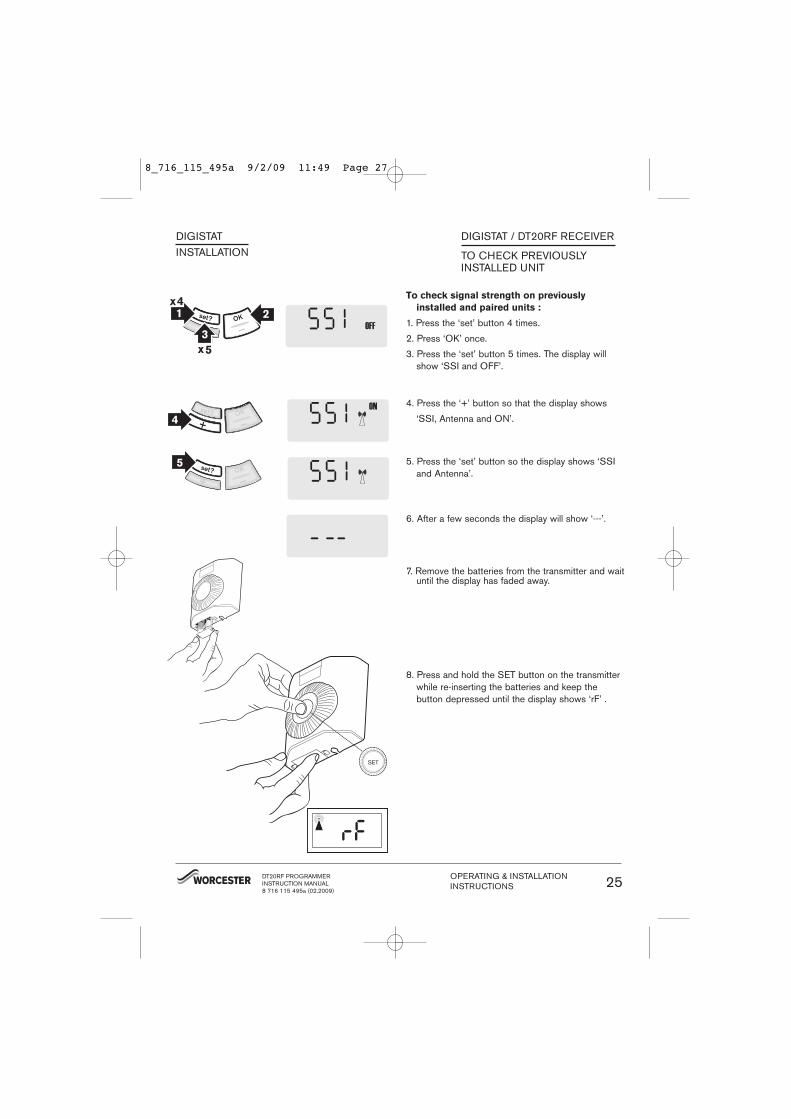
To check signal strength on previously
installed and paired units :
1. Press the ‘set’ button 4 times.
2. Press ‘OK’ once.
3. Press the ‘set’ button 5 times. The display willshow ‘SSI and OFF’.
4. Press the ‘+’ button so that the display shows
‘SSI, Antenna and ON’.
5. Press the ‘set’ button so the display shows ‘SSIand Antenna’.
6. After a few seconds the display will show ‘---’.
7. Remove the batteries from the transmitter and waituntil the display has faded away.
8. Press and hold the SET button on the transmitterwhile re-inserting the batteries and keep thebutton depressed until the display shows ‘rF’ .
DT20RF PROGRAMMERINSTRUCTION MANUAL8 716 115 495a (02.2009)
OPERATING & INSTALLATIONINSTRUCTIONS 25
8_716_115_495a 9/2/09 11:49 Page 27
DIGISTATINSTALLATION
DIGISTAT / DT20RF RECEIVER
TO CHECK PREVIOUSLYINSTALLED UNIT
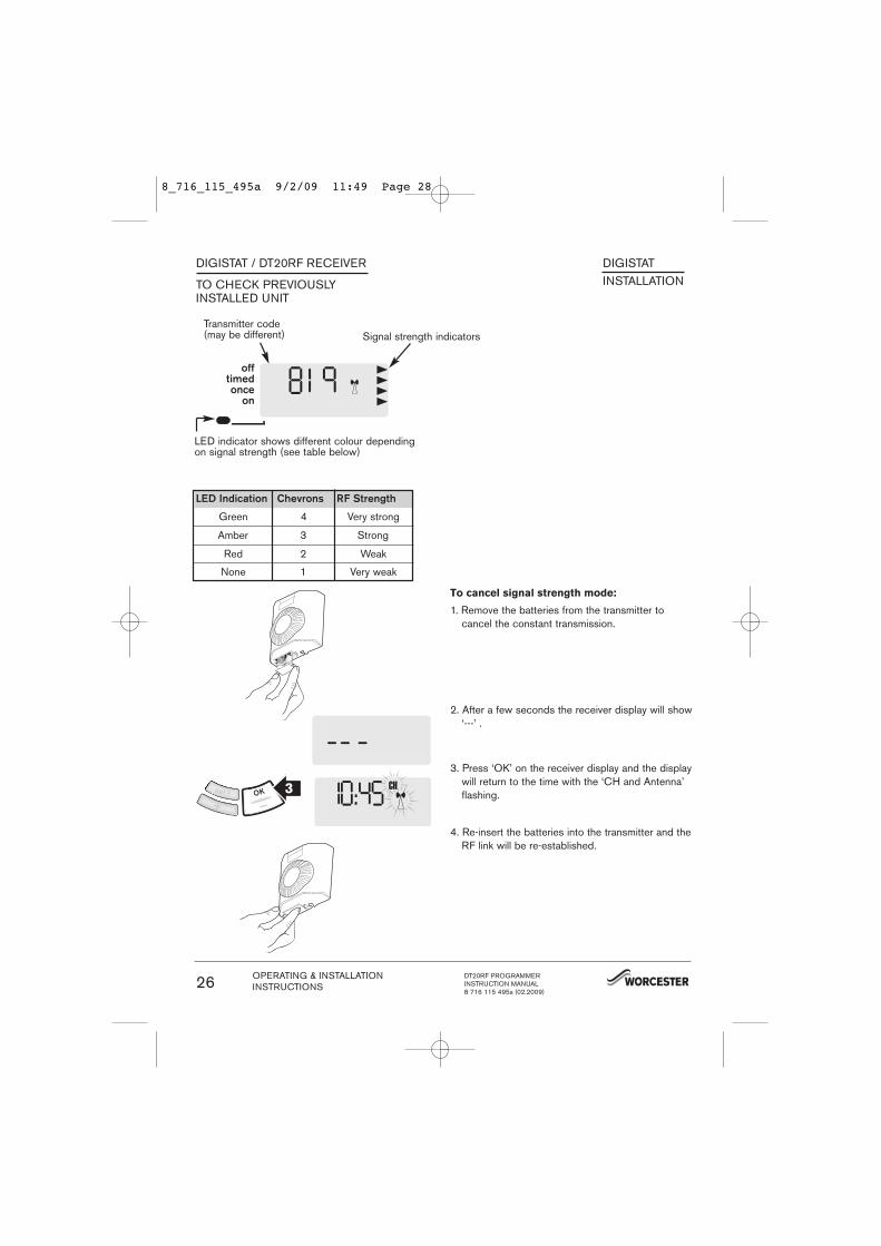
Signal strength indicatorsTransmitter code(may be different)
LED indicator shows different colour dependingon signal strength (see table below)
LED Indication Chevrons RF Strength
Green
Amber
Red
None
4
3
2
1
Very strong
Strong
Weak
Very weak
To cancel signal strength mode:
1. Remove the batteries from the transmitter tocancel the constant transmission.
2. After a few seconds the receiver display will show‘---’ .
3. Press ‘OK’ on the receiver display and the displaywill return to the time with the ‘CH and Antenna’flashing.
4. Re-insert the batteries into the transmitter and theRF link will be re-established.
OPERATING & INSTALLATIONINSTRUCTIONS
DT20RF PROGRAMMERINSTRUCTION MANUAL8 716 115 495a (02.2009)
26
8_716_115_495a 9/2/09 11:49 Page 28
DIGISTATINSTALLATION
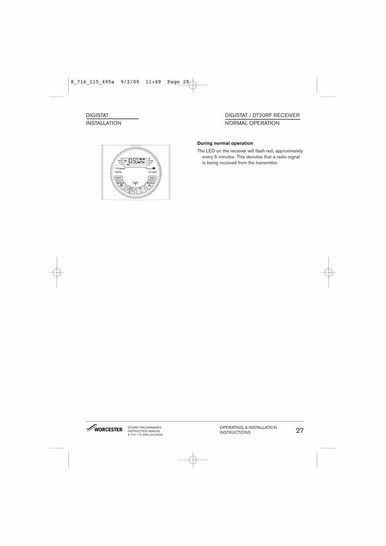
During normal operation
The LED on the receiver will flash red, approximatelyevery 5 minutes. This denotes that a radio signalis being received from the transmitter.
DIGISTAT / DT20RF RECEIVERNORMAL OPERATION
DT20RF PROGRAMMERINSTRUCTION MANUAL8 716 115 495a (02.2009)
OPERATING & INSTALLATIONINSTRUCTIONS 27
8_716_115_495a 9/2/09 11:49 Page 29

Maintenance:
The Digistat RF Room thermostat requires no maintenance.The outer casing can be wiped clean using a drycloth. DO NOT use polish or detergents.
These units can not be serviced.Should the existing units fail to function correctly,check that the:� DT20RF Receiver times and program settings
are correct.� RF signal link is set up (Refer to page 2 for
RF signal range details).� Digistat RF Room thermostat batteries are the
correct type, fitted correctly and are notexhausted. Fit new batteries if in doubt.
DIGISTAT/DT20RF RECEIVER MAINTENANCE
DT20RF Receiver
part number 8 716 106 669 0
Digistat RF Room thermostat
part number 8 716 114 463 0
OPERATING & INSTALLATIONINSTRUCTIONS
DT20RF PROGRAMMERINSTRUCTION MANUAL8 716 115 495a (02.2009)
28
8_716_115_495a 9/2/09 11:49 Page 30

8_716_115_495a 9/2/09 11:49 Page 31
Worcester, Bosch Group
Cotswold Way, Warndon, Worcester WR4 9SW.
Tel. 01905 754624 Fax. 01905 754619
worcester-bosch.co.uk
Worcester, Bosch Group is a brand name of Bosch Thermotechnology Ltd.
8 716 115 495a (02.2009) 06515058001 ISSB
CONTACT INFORMATION
WORCESTER, BOSCH GROUP:
TECHNICAL: 08705 266241
SERVICE: 08457 256206
SPARES: 01905 752571
LITERATURE: 01905 752556
TRAINING: 01905 752526
SALES: 01905 752640
WEBSITE: worcester-bosch.co.uk
WEBSITE (EIRE): worcester-bosch.ie
8_716_115_495a 9/2/09 11:49 Page 32