Embed Size (px)
DESCRIPTION
Â
Citation preview

Auto. Basic Electrical Auto. Basic Electrical Milwaukee Area Technical CollegeMilwaukee Area Technical College
10-602-101 Automotive Basic Electrical (2cr.)
Presenter: David Schwid

Auto. Basic Electrical Auto. Basic Electrical Milwaukee Area Technical CollegeMilwaukee Area Technical College
Lesson 2: Atoms•Smallest part of an element •Still has all the characteristics of that element•Can be solid, liquid, or gas.

Auto. Basic Electrical Auto. Basic Electrical Milwaukee Area Technical CollegeMilwaukee Area Technical College
Atoms•Atoms consist of three parts:
A. Protons (positively charged)
B. Neutrons (neutral
charged)C. Electrons (negatively charged)

Auto. Basic Electrical Auto. Basic Electrical Milwaukee Area Technical CollegeMilwaukee Area Technical College
AtomsPositive and negative charges act
like those in a magnet

Auto. Basic Electrical Auto. Basic Electrical Milwaukee Area Technical CollegeMilwaukee Area Technical College 5
Electron flowAll electrons do not travel in the same orbit. All electrons do not travel in the same orbit. Some are closer to the nucleus and some are Some are closer to the nucleus and some are farther away. The electrons in the outer orbits farther away. The electrons in the outer orbits are sometimes called “free” electrons.are sometimes called “free” electrons.
The outer ring is called a valance ring and the The outer ring is called a valance ring and the electrons in the outer orbits may also be electrons in the outer orbits may also be called valance electrons.called valance electrons.
Elements with 1-3 valance electrons are Elements with 1-3 valance electrons are usually good usually good conductors.conductors.
Elements with 4 valance electrons are Elements with 4 valance electrons are semi-semi-conductors.conductors.
Elements with 5 or more valance electrons Elements with 5 or more valance electrons are usually good are usually good insulators.insulators.
Auto. Basic Electrical Auto. Basic Electrical Milwaukee Area Technical CollegeMilwaukee Area Technical College
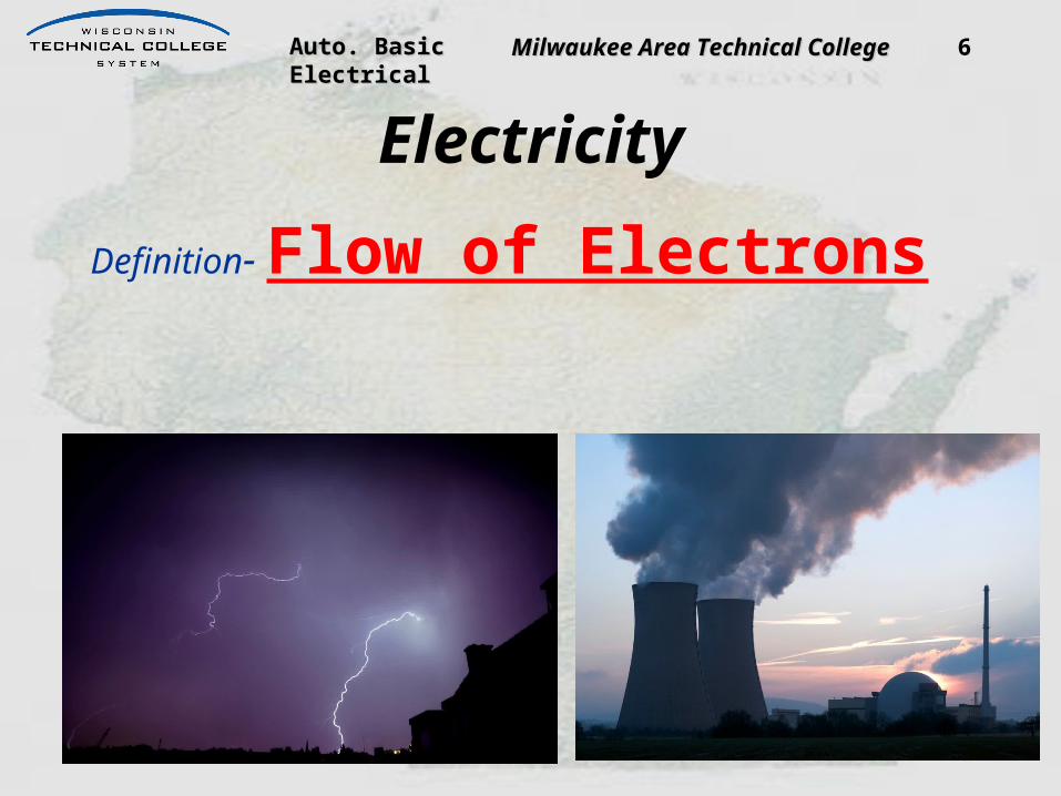
ElectricityDefinition- Flow of Electrons
6

Auto. Basic Electrical Auto. Basic Electrical Milwaukee Area Technical CollegeMilwaukee Area Technical College
Conductors• Allow the flow of electricity• Contain atoms with free electrons
– 1 to 3 electrons in the outer orbit• Free electrons are not locked in orbit
around the nucleus– electrons can be forced to move from one
atom to another• Copper, gold, and silver are good
conductors
Auto. Basic Electrical Auto. Basic Electrical Milwaukee Area Technical CollegeMilwaukee Area Technical College
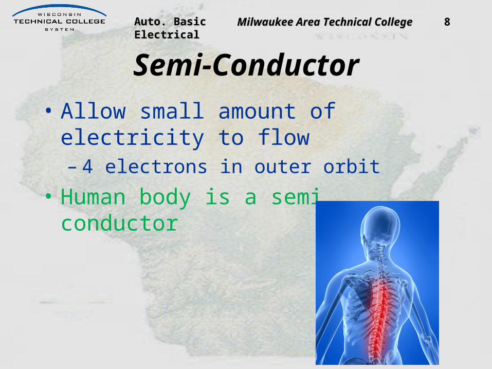
Semi-Conductor• Allow small amount of electricity to flow
– 4 electrons in outer orbit• Human body is a semi conductor
8

Auto. Basic Electrical Auto. Basic Electrical Milwaukee Area Technical CollegeMilwaukee Area Technical College
Insulators• Resist the flow of electricity• Contain atoms with bound electrons
– 5 to 8 electrons in the outer orbit• Bound electrons will not leave their orbit
around the nucleus• Plastic, rubber, and ceramics are good
insulators

Auto. Basic Electrical Auto. Basic Electrical Milwaukee Area Technical CollegeMilwaukee Area Technical College 10
Section 2: Lesson 1
Conductors/InsulatorsConductors are materials Conductors are materials
that allow current to flow that allow current to flow easily. easily.
Insulators are materials Insulators are materials that are very resistant to that are very resistant to current flow. Insulators current flow. Insulators are used to prevent an are used to prevent an unwanted current path.unwanted current path.
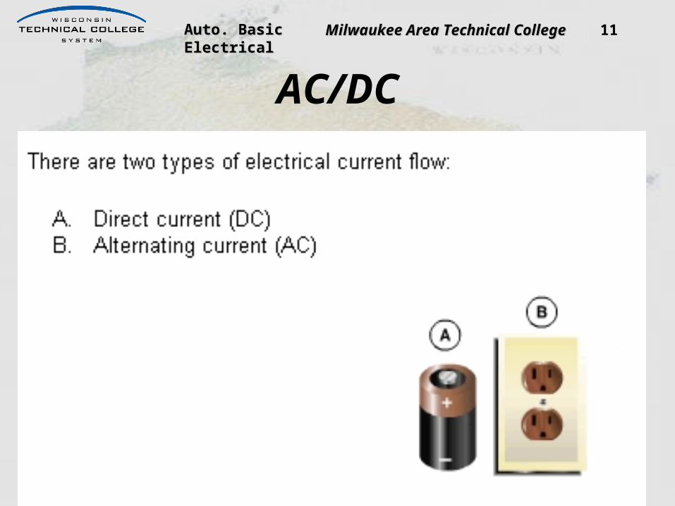
Auto. Basic Electrical Auto. Basic Electrical Milwaukee Area Technical CollegeMilwaukee Area Technical College 11
AC/DC
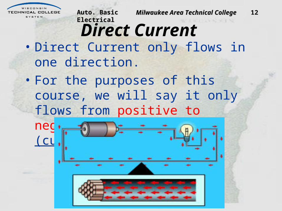
Auto. Basic Electrical Auto. Basic Electrical Milwaukee Area Technical CollegeMilwaukee Area Technical College 12
Direct Current• Direct Current only flows in one
direction.• For the purposes of this course, we will
say it only flows from positive to negative. Conventional (current) theory
Auto. Basic Electrical Auto. Basic Electrical Milwaukee Area Technical CollegeMilwaukee Area Technical College 13
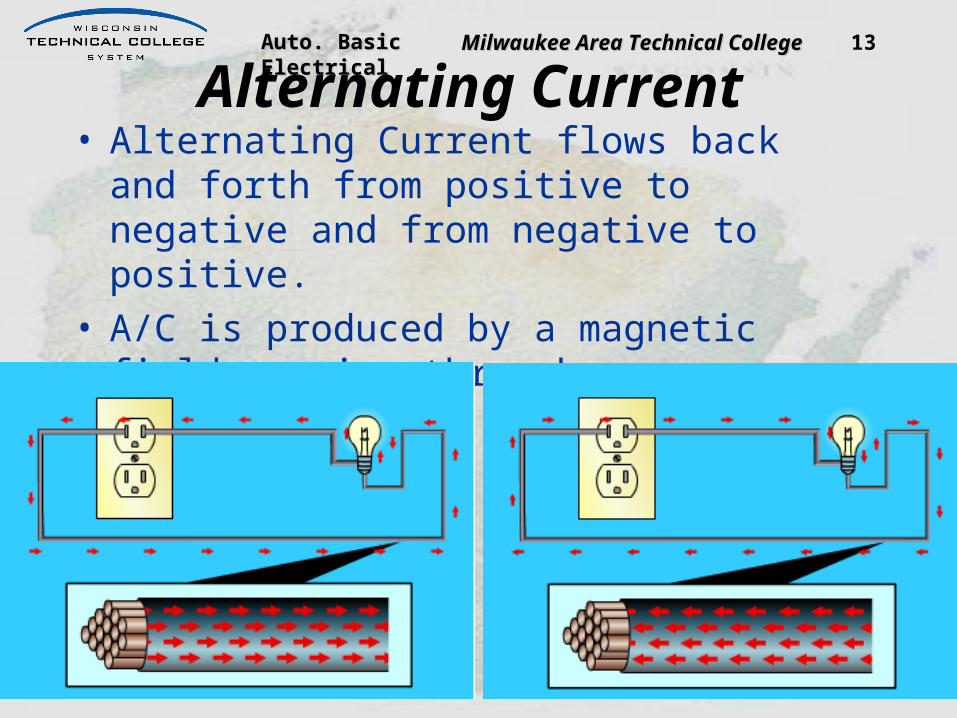
Alternating Current• Alternating Current flows back and forth from
positive to negative and from negative to positive.
• A/C is produced by a magnetic field passing through a conductor.

Auto. Basic Electrical Auto. Basic Electrical Milwaukee Area Technical CollegeMilwaukee Area Technical College 14
Lesson 3:Electromotive Force
VoltageVoltage is the “Electrical Pressure” Voltage is what pushes the electrons through the conductor. It can also be referred to as Potential Difference.
Hint: (think water pressure)

Auto. Basic Electrical Auto. Basic Electrical Milwaukee Area Technical CollegeMilwaukee Area Technical College
Amps• Current
– Number of electrons that flow past a point in one second
– Measured in Amperage
• Hint- (think Gallons per Minute)
15
Amperage is how we measure electron flow or current. One ampere or amp is 6.25 billion billion electrons past one point in one second!

Auto. Basic Electrical Auto. Basic Electrical Milwaukee Area Technical CollegeMilwaukee Area Technical College 16
Characteristics of Current• When current flows
through a conductor, it generates heat and magnetism. Energy is only transformed, it is never lost.

Auto. Basic Electrical Auto. Basic Electrical Milwaukee Area Technical CollegeMilwaukee Area Technical College 17
Resistance• Resistance is the opposition to flow of
electrons in a conductor. • Measured in ohms (Ω)• Hint- (think water facet)
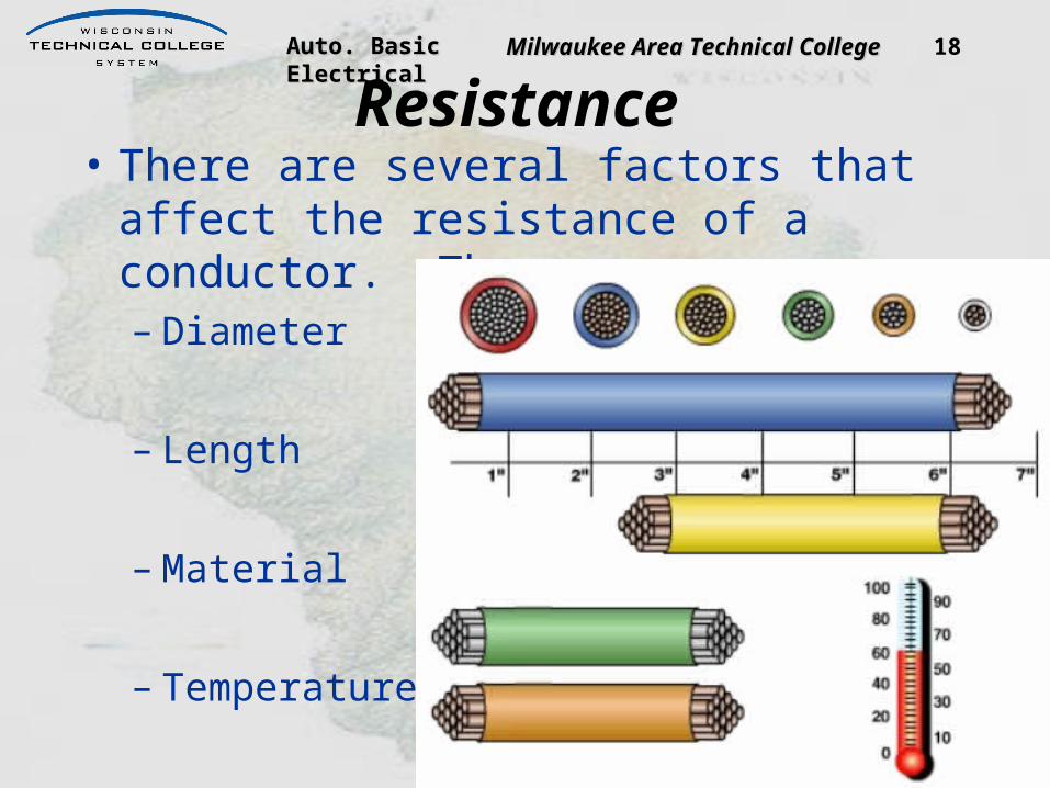
Auto. Basic Electrical Auto. Basic Electrical Milwaukee Area Technical CollegeMilwaukee Area Technical College 18
Resistance• There are several factors that affect the
resistance of a conductor. They are:– Diameter
– Length
– Material
– Temperature

Auto. Basic Electrical Auto. Basic Electrical Milwaukee Area Technical CollegeMilwaukee Area Technical College 19
WiresSome examples of different wires.– Solid Copper is
almost never used.– Hi-Flex 266 used in
ABS.– Multi-Stranded is
the most common.– Twisted & Shielded
used in signal and communications.
– Ribbon Wire for space savings.

Auto. Basic Electrical Auto. Basic Electrical Milwaukee Area Technical CollegeMilwaukee Area Technical College 20
Wire Size

Auto. Basic Electrical Auto. Basic Electrical Milwaukee Area Technical CollegeMilwaukee Area Technical College 21
Wire Stripping & Crimping

Auto. Basic Electrical Auto. Basic Electrical Milwaukee Area Technical CollegeMilwaukee Area Technical College 22
Soldering

Auto. Basic Electrical Auto. Basic Electrical Milwaukee Area Technical CollegeMilwaukee Area Technical College 23
Connectors and Terminal Repair

Auto. Basic Electrical Auto. Basic Electrical Milwaukee Area Technical CollegeMilwaukee Area Technical College 24
Lesson 5: Laws
Ohm’s Law

Auto. Basic Electrical Auto. Basic Electrical Milwaukee Area Technical CollegeMilwaukee Area Technical College 25
Ohm’s Law

Auto. Basic Electrical Auto. Basic Electrical Milwaukee Area Technical CollegeMilwaukee Area Technical College 26
Ohm’s Law
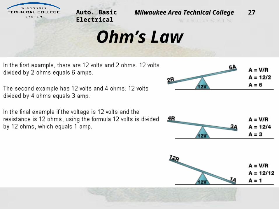
Auto. Basic Electrical Auto. Basic Electrical Milwaukee Area Technical CollegeMilwaukee Area Technical College 27
Ohm’s Law

Auto. Basic Electrical Auto. Basic Electrical Milwaukee Area Technical CollegeMilwaukee Area Technical College 28
Voltage Unknown
E= I x R

Auto. Basic Electrical Auto. Basic Electrical Milwaukee Area Technical CollegeMilwaukee Area Technical College 29
Resistance Unknown
R= E / I

Auto. Basic Electrical Auto. Basic Electrical Milwaukee Area Technical CollegeMilwaukee Area Technical College 30
Current Unknown
I= E / R

Auto. Basic Electrical Auto. Basic Electrical Milwaukee Area Technical CollegeMilwaukee Area Technical College
Simple Circuit• Three things
– Power supply– Conductor– Load

Auto. Basic Electrical Auto. Basic Electrical Milwaukee Area Technical CollegeMilwaukee Area Technical College 32
Series CircuitCurrent is the same throughout the
circuit.

Auto. Basic Electrical Auto. Basic Electrical Milwaukee Area Technical CollegeMilwaukee Area Technical College 33
Series Circuit Rules
If voltage remains constant and resistance increases, amperage flow will decrease.
If voltage remains constant and resistance decreases, amperage flow will increase.

Auto. Basic Electrical Auto. Basic Electrical Milwaukee Area Technical CollegeMilwaukee Area Technical College 34
Parallel CircuitsThe total resistance of a parallel circuit will always be less than the resistance of any of it’s branches.

Auto. Basic Electrical Auto. Basic Electrical Milwaukee Area Technical CollegeMilwaukee Area Technical College 35
Parallel Circuit RulesThe total resistance of a parallel circuit will always be less than the resistance of any of it’s branches.The voltage applied to each branch is the same.The current flow through the branches will be different if the resistance is different.The voltage dropped across each branch will be the same.

Auto. Basic Electrical Auto. Basic Electrical Milwaukee Area Technical CollegeMilwaukee Area Technical College 36
Parallel Circuits– The voltage applied to each branch is
the same.

Auto. Basic Electrical Auto. Basic Electrical Milwaukee Area Technical CollegeMilwaukee Area Technical College 37
Parallel CircuitsThe current flow through the branches will be different if the resistance is different.

Auto. Basic Electrical Auto. Basic Electrical Milwaukee Area Technical CollegeMilwaukee Area Technical College 38
Parallel Branch Amperage As more branches are added, more
amperage flows.

Auto. Basic Electrical Auto. Basic Electrical Milwaukee Area Technical CollegeMilwaukee Area Technical College 39
Series-Parallel CircuitCalculate the total resistance of the parallel circuit first, using the appropriate formula.Add that to the total resistance of the series portion of the circuit.This will give us the total resistance of the circuit.
– Now we can calculate the total circuit current flow, because we know what the source voltage is.
I = E / R

Auto. Basic Electrical Auto. Basic Electrical Milwaukee Area Technical CollegeMilwaukee Area Technical College
Circuit Faults• Open- Break in Circuit• Short- Two positive wires touching• Short to Ground- positive wire touching
ground• High resistance- Bad connection
40

Auto. Basic Electrical Auto. Basic Electrical Milwaukee Area Technical CollegeMilwaukee Area Technical College 41
Open•No completed path to ground
– Series circuit– Parallel Circuit

Auto. Basic Electrical Auto. Basic Electrical Milwaukee Area Technical CollegeMilwaukee Area Technical College 42
Short to Ground•Before the load
– Protection device opens– Why?– Resistance decreased– Current increased

Auto. Basic Electrical Auto. Basic Electrical Milwaukee Area Technical CollegeMilwaukee Area Technical College 43
Short to Ground•After the load
– Load stays on if ground side switched
– If close to intended ground, no noticeable effect

Auto. Basic Electrical Auto. Basic Electrical Milwaukee Area Technical CollegeMilwaukee Area Technical College 44
Short to Power•One or more circuits may operate strangely
– Figure 8-3, view A, both switches control both loads– Figure 8-3, view B, short to ground

Auto. Basic Electrical Auto. Basic Electrical Milwaukee Area Technical CollegeMilwaukee Area Technical College 45
Too Much Resistance•Dirt or Corrosion
– As resistance increases– Current flow decreases– Voltage needed to operate load drops
in another part of the circuit

Auto. Basic Electrical Auto. Basic Electrical Milwaukee Area Technical CollegeMilwaukee Area Technical College 46
Reading the Meter• Types
– Digital• Manual Ranging• Auto Ranging
– Analog• Analog has low
internal impedance/allowing more current to flow
• Do Not Use on any computer controlled circuits
Auto. Basic Electrical Auto. Basic Electrical Milwaukee Area Technical CollegeMilwaukee Area Technical College 47
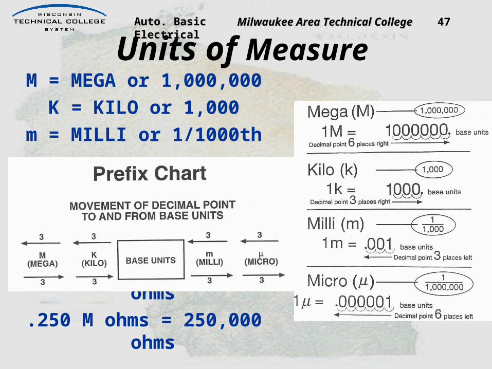
Units of MeasureM = MEGA or 1,000,000
K = KILO or 1,000m = MILLI or 1/1000th
2.5 M ohms = 2,500,000 ohms.250 M ohms = 250,000 ohms
Auto. Basic Electrical Auto. Basic Electrical Milwaukee Area Technical CollegeMilwaukee Area Technical College 48
Mega Mega stands for one million and is abbreviated with a capitalletter M. One mega ohm equals one million ohms. To convertany value from mega ohms to ohms, move the decimal point sixplaces to the right. For example, 3.5 mega ohms will convert to3,500,000 ohms.
Kilo Kilo means one thousand and is abbreviated with a lowercase letter k. A kilo ohm is equal to 1,000 ohms. To convert any value from kilo ohm to ohms, move the decimal point three places to the right.
For example, .657 kilo ohms will covert to 657 ohms.
Base Units
Base units are standard units without a prefix. Volts, ohms, and amperes are the primary base units used in electronics. Prefixes are added to base units to change the unit of measurement.

Auto. Basic Electrical Auto. Basic Electrical Milwaukee Area Technical CollegeMilwaukee Area Technical College 49
Milli Milli stands for one thousandth and is abbreviated by the lowercase letter m. A milli ampere is one-thousandth of one ampere. To convert any value from milli amperes to amperes, move the decimal point three places to the left. For example, 0.355 milli amps will convert to .000355 amps.
MicroMicro means one millionth and is abbreviated by the symbol u. A microampere is equal to one millionth of an amp. To convert any value from microamperes to amperes, move the decimal point six places to the left. For example, 355 microamperes will covert to .000355 amps.

Auto. Basic Electrical Auto. Basic Electrical Milwaukee Area Technical CollegeMilwaukee Area Technical College 50
Reading the Meter
You must know what to expect before taking the reading…….or you’re wasting your time!
Auto. Basic Electrical Auto. Basic Electrical Milwaukee Area Technical CollegeMilwaukee Area Technical College 51
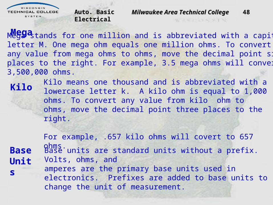
Lesson 2:Circuit Protection
Devices designed to open the Devices designed to open the circuit in the event of too much circuit in the event of too much current flow.current flow.
FuseFuse
Fusible LinkFusible Link
Circuit BreakerCircuit Breaker

Auto. Basic Electrical Auto. Basic Electrical Milwaukee Area Technical CollegeMilwaukee Area Technical College 52
Switches
Auto. Basic Electrical Auto. Basic Electrical Milwaukee Area Technical CollegeMilwaukee Area Technical College 53
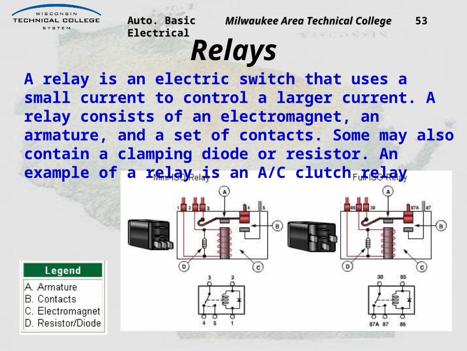
RelaysA relay is an electric switch that uses a small current to control a larger current. A relay consists of an electromagnet, an armature, and a set of contacts. Some may also contain a clamping diode or resistor. An example of a relay is an A/C clutch relay

Auto. Basic Electrical Auto. Basic Electrical Milwaukee Area Technical CollegeMilwaukee Area Technical College 54
RelaysA control circuit (primary circuit) is used to provide current to the electromagnet. The electromagnet is energized and pulls the armature toward it. The movement of the armature closes the normally open contacts (secondary circuit). When the contacts close they provide a path for current to reach the load.

Auto. Basic Electrical Auto. Basic Electrical Milwaukee Area Technical CollegeMilwaukee Area Technical College 55
RelaysWhen the electromagnet is de-energized, current reverses and produces a voltage spike. This spike results from the collapsing of the magnetic field around the coil. Voltage spikes can damage electronic components. To prevent this spike, a clamping diode or resistor is wired in parallel with the relay coil, providing a path for this current to return back to the coil without causing harm to the electronic components.

Auto. Basic Electrical Auto. Basic Electrical Milwaukee Area Technical CollegeMilwaukee Area Technical College 56
Section 3: Lesson 1
Electrical Measurement DVOM Setup
Click on the Following Link for an animated learning object about:Wisc-Online: Digital Multimeter/Ohmmeter Measurement Connections
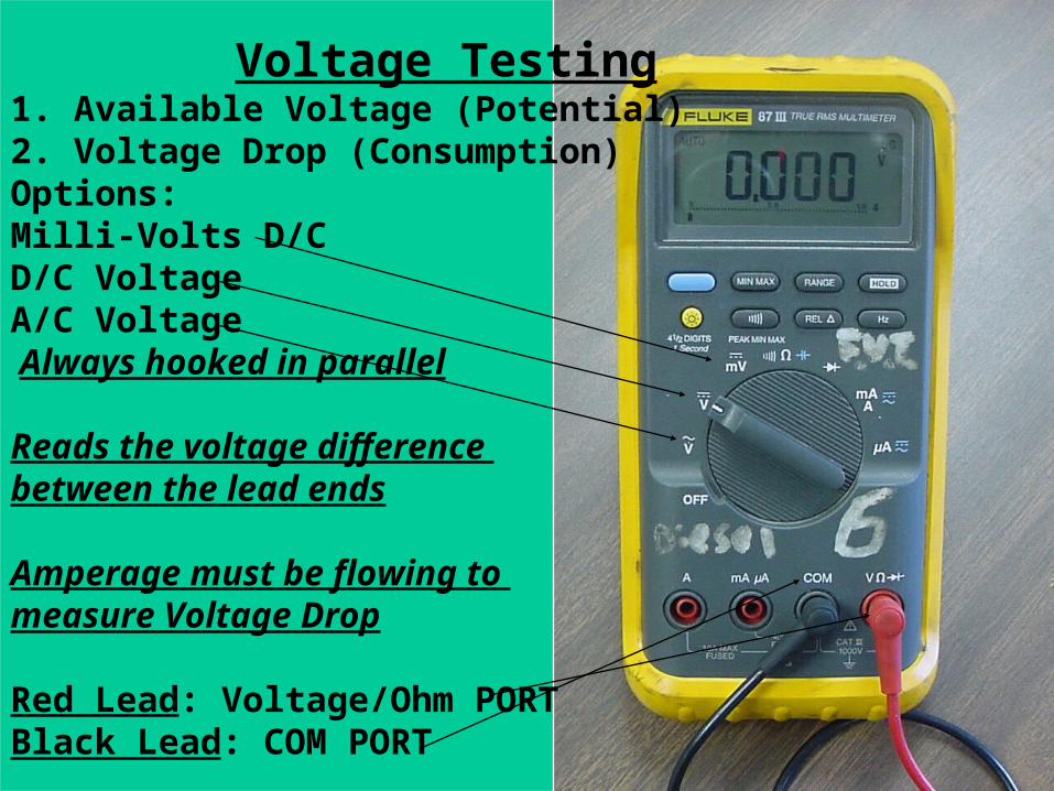
Auto. Basic Electrical Auto. Basic Electrical Milwaukee Area Technical CollegeMilwaukee Area Technical College 57 Voltage Testing1. Available Voltage (Potential)2. Voltage Drop (Consumption)Options:Milli-Volts D/C D/C VoltageA/C Voltage Always hooked in parallel
Reads the voltage difference between the lead ends
Amperage must be flowing to measure Voltage Drop
Red Lead: Voltage/Ohm PORTBlack Lead: COM PORT

Auto. Basic Electrical Auto. Basic Electrical Milwaukee Area Technical CollegeMilwaukee Area Technical College 58
Amperage Testing
A/C or D/C Amperage
Options:Milli-Amps/AmpsMicro-Amps
Red Lead: Amp Port (10 amp max)or milli-amp / micro amp portBlack Lead: COM Port
Always hooked in SeriesAmperage must be flowing to measure

Auto. Basic Electrical Auto. Basic Electrical Milwaukee Area Technical CollegeMilwaukee Area Technical College 59 Amp Testing Inductive Clamp or “Pick-Up”Capable of reading 400 Amps
Place around 1 wire -Not required to place inseries
Amperage must be flowing to measure
Dial set to D/C mV scale
Red Lead: Voltage PortBlack Lead: COM Port
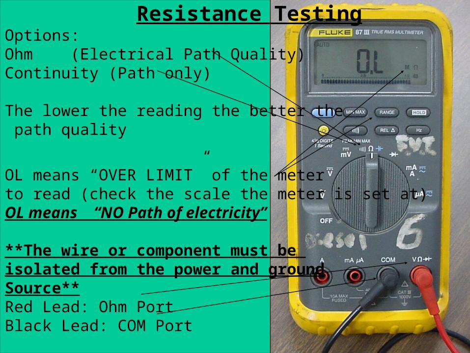
Auto. Basic Electrical Auto. Basic Electrical Milwaukee Area Technical CollegeMilwaukee Area Technical College 60 Resistance TestingOptions:Ohm (Electrical Path Quality)Continuity (Path only)
The lower the reading the better the path quality
OL means “OVER LIMIT” of the meterto read (check the scale the meter is set at)OL means “NO Path of electricity”
**The wire or component must be isolated from the power and groundSource**Red Lead: Ohm PortBlack Lead: COM Port

Auto. Basic Electrical Auto. Basic Electrical Milwaukee Area Technical CollegeMilwaukee Area Technical College 61
Diode Testing
Performs a continuity test with a higheroutput voltage to “Turn On” the diode.
The meter will read the voltage output
Red Lead: Volt/Ohms/Continuity PortBlack Lead: COM Port
Auto. Basic Electrical Auto. Basic Electrical Milwaukee Area Technical CollegeMilwaukee Area Technical College 62
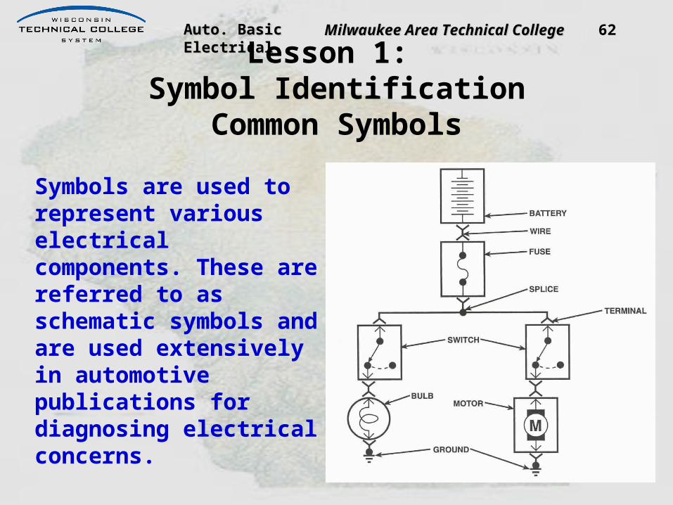
Lesson 1: Symbol Identification
Common Symbols
Symbols are used to represent various electrical components. These are referred to as schematic symbols and are used extensively in automotive publications for diagnosing electrical concerns.

Auto. Basic Electrical Auto. Basic Electrical Milwaukee Area Technical CollegeMilwaukee Area Technical College 63
Ground Symbol
Because automotive circuits share a common ground, that is, a return path to the battery, a special ground symbol is used to simplify circuit diagrams.
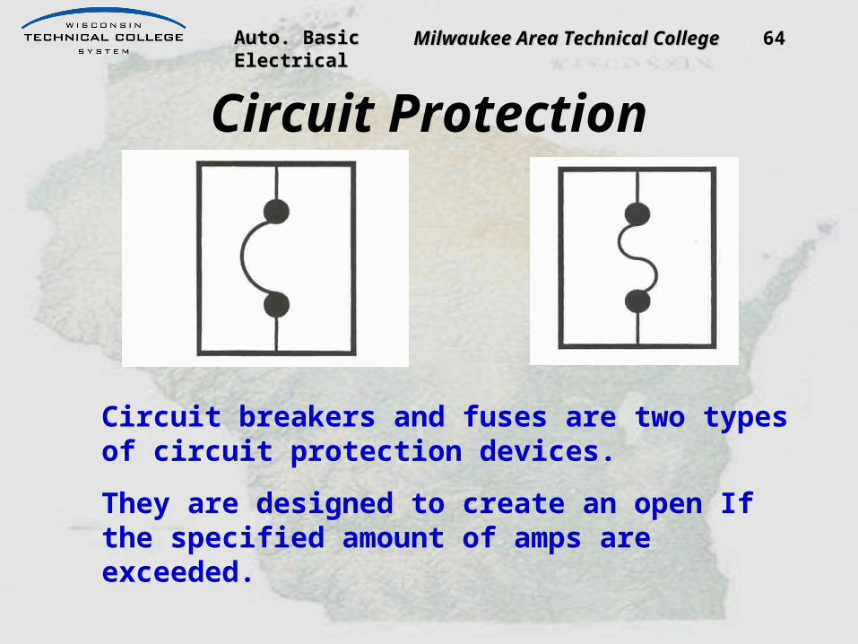
Auto. Basic Electrical Auto. Basic Electrical Milwaukee Area Technical CollegeMilwaukee Area Technical College 64
Circuit Protection
Circuit breakers and fuses are two types of circuit protection devices.
They are designed to create an open If the specified amount of amps are exceeded.

Auto. Basic Electrical Auto. Basic Electrical Milwaukee Area Technical CollegeMilwaukee Area Technical College 65
Resistors
Resistors are used to limit current, divide voltage, and in certain applications, generate heat. There are a variety of resistors classified into two main categories: fixed and variable.

Auto. Basic Electrical Auto. Basic Electrical Milwaukee Area Technical CollegeMilwaukee Area Technical College 66
Wire and Wire Symbols
Wire is the most common type of conductive material used to connect components.
Wire is available in different sizes called gauge size.It is also available in both round and flat types.
This is the symbol for wires that cross, but are not connected.

Auto. Basic Electrical Auto. Basic Electrical Milwaukee Area Technical CollegeMilwaukee Area Technical College 67
Splice
This is the symbol for wires that cross and are connected at a splice.

Auto. Basic Electrical Auto. Basic Electrical Milwaukee Area Technical CollegeMilwaukee Area Technical College 68
Continuation / Optional
A wavy line means a wire is to be continued somewhere else in the circuit. Typically, these lines are used to show a graphically shortened wire.

Auto. Basic Electrical Auto. Basic Electrical Milwaukee Area Technical CollegeMilwaukee Area Technical College 69
Continuation
An arrow symbol at the end of a wire with a letter inside of it indicates a wire continues as labeled on another page. For example, this wire connects to the generator, but it is shown on another page. The symbol is then repeated on that page. The arrow indicates the direction of current flow.

Auto. Basic Electrical Auto. Basic Electrical Milwaukee Area Technical CollegeMilwaukee Area Technical College 70
SwitchSwitches are most commonly used to control a circuit by either allowing or restricting voltage flow. Switches can be mechanical, or electromechanical, or electronic. Switches can be in a multiple of different configurations, such as SPST (single pole, single throw).

Auto. Basic Electrical Auto. Basic Electrical Milwaukee Area Technical CollegeMilwaukee Area Technical College 71
Battery
A battery provides a source voltage for an electrical/electronic circuit. Most batteries work by the conversion of a chemical reaction into electricity.

Auto. Basic Electrical Auto. Basic Electrical Milwaukee Area Technical CollegeMilwaukee Area Technical College 72
Motor
A motor provides the conversion of electrical potential into amoving mechanical energy.

Auto. Basic Electrical Auto. Basic Electrical Milwaukee Area Technical CollegeMilwaukee Area Technical College 73
Light Bulb
A light bulb converts electrical energy into a radiant light. The filament resists electrical flow and heats up, causing the filament to glow.

Auto. Basic Electrical Auto. Basic Electrical Milwaukee Area Technical CollegeMilwaukee Area Technical College
Blower Motor Circuits• Power flow in
High Speed– Feed Power– Switched
Power– Switched
Ground– Hard Ground

Auto. Basic Electrical Auto. Basic Electrical Milwaukee Area Technical CollegeMilwaukee Area Technical College
Blower Motor Circuits• Power flow in
Medium High (M2) Speed – Feed Power– Switched
Power– Switched
Ground– Hard Ground
Auto. Basic Electrical Auto. Basic Electrical Milwaukee Area Technical CollegeMilwaukee Area Technical College 76
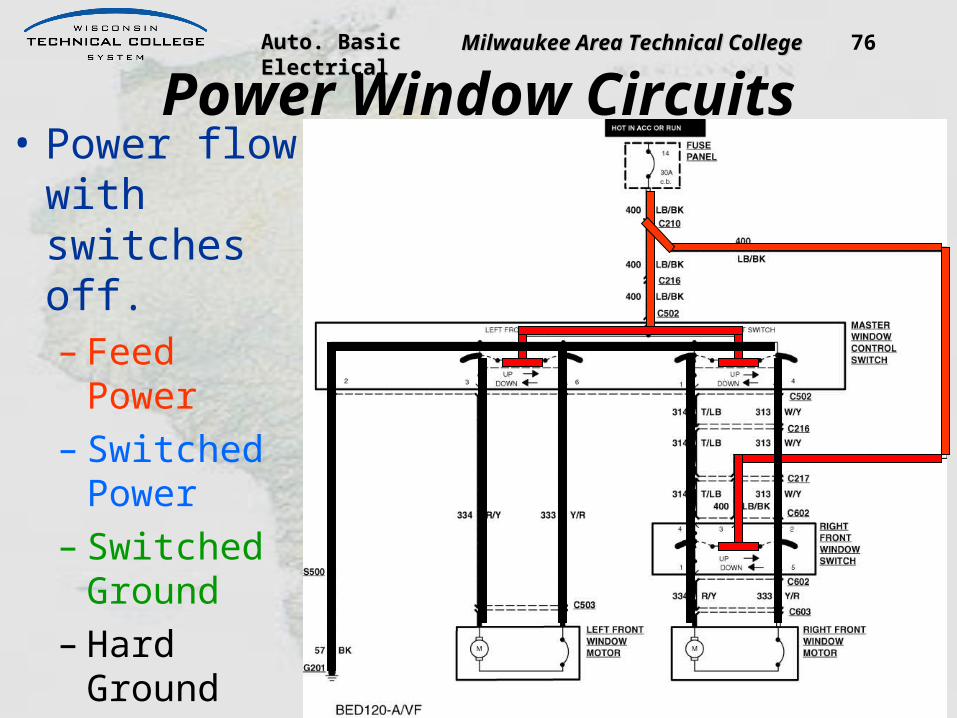
Power Window Circuits• Power flow
with switches off.– Feed Power– Switched
Power– Switched
Ground– Hard
Ground
Auto. Basic Electrical Auto. Basic Electrical Milwaukee Area Technical CollegeMilwaukee Area Technical College 77
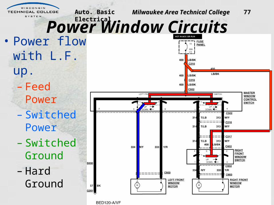
Power Window Circuits• Power flow
with L.F. up.– Feed Power– Switched
Power– Switched
Ground– Hard
Ground

Auto. Basic Electrical Auto. Basic Electrical Milwaukee Area Technical CollegeMilwaukee Area Technical College 78
Power Window Circuits• Power flow
with L.F. down.– Feed Power– Switched
Power– Switched
Ground– Hard
Ground

Auto. Basic Electrical Auto. Basic Electrical Milwaukee Area Technical CollegeMilwaukee Area Technical College 79
Power Window Circuits• Power flow
with R.F. control down.– Feed Power– Switched
Power– Switched
Ground– Hard
Ground

Auto. Basic Electrical Auto. Basic Electrical Milwaukee Area Technical CollegeMilwaukee Area Technical College 80
• What voltages should you read at the given points?
• Where should you place the leads?
Power Window Circuit Diag.
Auto. Basic Electrical Auto. Basic Electrical Milwaukee Area Technical CollegeMilwaukee Area Technical College 81
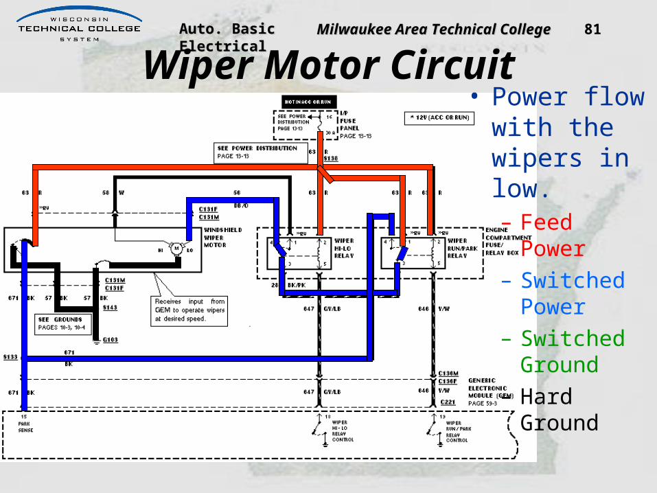
Wiper Motor Circuit• Power flow
with the wipers in low.– Feed Power– Switched
Power– Switched
Ground– Hard Ground

Auto. Basic Electrical Auto. Basic Electrical Milwaukee Area Technical CollegeMilwaukee Area Technical College 82
Wiper Motor Circuit• Power flow
with the wipers in high.– Feed Power– Switched
Power– Switched
Ground– Hard Ground

Auto. Basic Electrical Auto. Basic Electrical Milwaukee Area Technical CollegeMilwaukee Area Technical College 83
Wiper Motor Circuit• Power flow
with the wipers going to park.– Feed Power– Switched
Power– Switched
Ground– Hard Ground

Auto. Basic Electrical Auto. Basic Electrical Milwaukee Area Technical CollegeMilwaukee Area Technical College 84
Wiper Motor Circuit• Power flow
with the wipers parked.– Feed Power– Switched
Power– Switched
Ground– Hard Ground

Auto. Basic Electrical Auto. Basic Electrical Milwaukee Area Technical CollegeMilwaukee Area Technical College 85
Wiper Motor Circuit Diag.• What
voltages should you read at the given points?
• Where should you place the leads?

Auto. Basic Electrical Auto. Basic Electrical Milwaukee Area Technical CollegeMilwaukee Area Technical College

Auto. Basic Electrical Auto. Basic Electrical Milwaukee Area Technical CollegeMilwaukee Area Technical College
• An automotive battery is an electrochemical device
• It produces and stores direct current electricity

Auto. Basic Electrical Auto. Basic Electrical Milwaukee Area Technical CollegeMilwaukee Area Technical College
Batteries
The battery provides the electricity to power all systems of the vehicle
when the engine is not running. When the engine is running, the charging system supplies all the
electricity to power the systems of the vehicle and the battery helps to
stabilize voltage for the entire electrical system.

Auto. Basic Electrical Auto. Basic Electrical Milwaukee Area Technical CollegeMilwaukee Area Technical College
Battery Parts

Auto. Basic Electrical Auto. Basic Electrical Milwaukee Area Technical CollegeMilwaukee Area Technical College
Discharging• Changes chemical energy into electrical
energy• Stored energy is released
ChargingElectrical energy is converted to
chemical energyEnergy is stored until needed

Auto. Basic Electrical Auto. Basic Electrical Milwaukee Area Technical CollegeMilwaukee Area Technical College
Lead-Acid Battery Cell
Electrolyte causes a chemical reaction between the plates, producing 2.1 volts

Auto. Basic Electrical Auto. Basic Electrical Milwaukee Area Technical CollegeMilwaukee Area Technical College
Battery Element
Most automotive batteries havesix elements

Auto. Basic Electrical Auto. Basic Electrical Milwaukee Area Technical CollegeMilwaukee Area Technical College
Battery Voltage• Open circuit cell voltage is 2.1 volts• Cells are connected in series• Battery voltage depends on the number
of cells• 12 volt battery has 6 cells - open circuit
voltage 12.6 volts• 6 volt battery has 3 cells - open circuit
voltage 6.3 volts

Auto. Basic Electrical Auto. Basic Electrical Milwaukee Area Technical CollegeMilwaukee Area Technical College
Batteries BATTERY STATE OF CHARGE
Once fully charged, a 12 volt battery will produce 2.1 volts per cell. For example, a 12 volt battery =
2.1 volts x 6 cells = 12.6 volts.

Auto. Basic Electrical Auto. Basic Electrical Milwaukee Area Technical CollegeMilwaukee Area Technical College
Battery Voltage

Auto. Basic Electrical Auto. Basic Electrical Milwaukee Area Technical CollegeMilwaukee Area Technical College
Cell Action(Charging)
• Alternator causes free electrons to be deposited on the negative (–) plate
• This causes the plates to have a difference in potential (voltage)

Auto. Basic Electrical Auto. Basic Electrical Milwaukee Area Technical CollegeMilwaukee Area Technical College
Cell Action(Discharging)
• Load is connected across the terminals• Current flows through the load to
equalize the difference in charges on the plates
• Excess electrons (current) move from the negative plate through the load to the positive plate

Auto. Basic Electrical Auto. Basic Electrical Milwaukee Area Technical CollegeMilwaukee Area Technical College
Battery Cycling
Auto. Basic Electrical Auto. Basic Electrical Milwaukee Area Technical CollegeMilwaukee Area Technical College
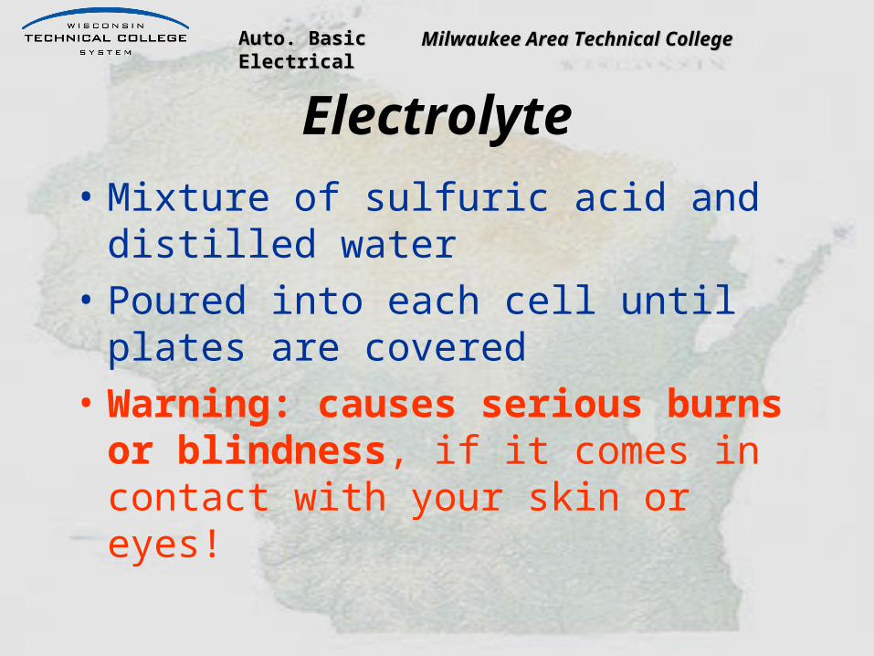
Electrolyte• Mixture of sulfuric acid and distilled
water• Poured into each cell until plates are
covered• Warning: causes serious burns or
blindness, if it comes in contact with your skin or eyes!

Auto. Basic Electrical Auto. Basic Electrical Milwaukee Area Technical CollegeMilwaukee Area Technical College
Batteries BATTERY STATE OF CHARGE:
With a maintenance possible battery, the technician can check the charge in each cell with a
hydrometer. A hydrometer measures the specific gravity of the electrolyte. If the battery is fully
charged it will have a specific gravity of 1.265. The lower the specific gravity the weaker the charge.

Auto. Basic Electrical Auto. Basic Electrical Milwaukee Area Technical CollegeMilwaukee Area Technical College
Hydrometer Check• Measures specific gravity (SG)• Compares weight of electrolyte to water• Water has a SG of 1.0• Electrolyte in a fully charged battery is
more dense with a SG of 1.265 to 1.299• As a battery becomes discharged,
electrolyte has a higher percentage of water, and a lower SG

Auto. Basic Electrical Auto. Basic Electrical Milwaukee Area Technical CollegeMilwaukee Area Technical College
• Does not use removable filler caps• Calcium is used to make the plates,
reducing gassing• Reduced water loss decreases service
requirements

Auto. Basic Electrical Auto. Basic Electrical Milwaukee Area Technical CollegeMilwaukee Area Technical College
Batteries BATTERY STATE OF CHARGE
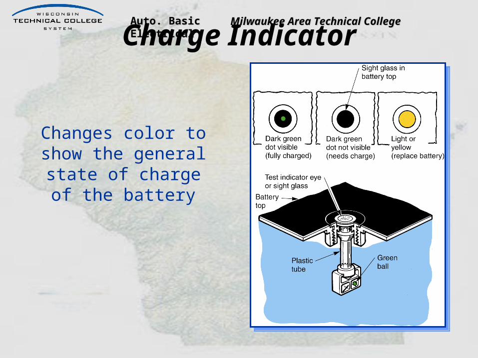
Auto. Basic Electrical Auto. Basic Electrical Milwaukee Area Technical CollegeMilwaukee Area Technical CollegeCharge Indicator
Changes color to show the general state of charge of
the battery

Auto. Basic Electrical Auto. Basic Electrical Milwaukee Area Technical CollegeMilwaukee Area Technical College
Battery Terminals
Means of connecting the battery to the
vehicle’s electrical system

Auto. Basic Electrical Auto. Basic Electrical Milwaukee Area Technical CollegeMilwaukee Area Technical College
Two-Battery Systems• Parallel
– connected negative to negative– connected positive to positive– two 12 volt batteries produce 12 volts, high
current• Series
– connected positive to negative– two 12 volt batteries produce 24 volts

Auto. Basic Electrical Auto. Basic Electrical Milwaukee Area Technical CollegeMilwaukee Area Technical College
Battery Cables
A. Post-typeB. Side terminalC. Braided groundD. 90º post-typeE. Solenoid to
starter

Auto. Basic Electrical Auto. Basic Electrical Milwaukee Area Technical CollegeMilwaukee Area Technical College
Cable Connections
Negative grounds engine block and positive connects
to electrical system

Auto. Basic Electrical Auto. Basic Electrical Milwaukee Area Technical CollegeMilwaukee Area Technical CollegeWet- and Dry-Charged Batteries
• Wet-Charged Battery– Filled with electrolyte and charged at
the factory– Very common in many locations
• Dry-Charged Battery– Contains fully charged elements– Does not contain electrolyte– Leaves the factory in a dry state– Has a long shelf life

Auto. Basic Electrical Auto. Basic Electrical Milwaukee Area Technical CollegeMilwaukee Area Technical College
Cold Cranking Rating• Determines the current that the battery
can deliver for 30 seconds at 0 ºF (-18 ºC) while maintaining terminal voltage of 7.2 volts (1.2 volts per cell)
• Expressed as cold cranking amps (CCA)• Indicates ability to crank the engine at cold
temperatures• Typical applications:
– 305 CCA for small 4 cylinder engine– 450 CCA for 8 cylinder engine

Auto. Basic Electrical Auto. Basic Electrical Milwaukee Area Technical CollegeMilwaukee Area Technical College 111
Battery Sizes and Ratings• CCA (Cold Cranking Amps)
– # of Amps produced in 30 seconds
– 0 deg. F– Maintaining at least 7.2V.
Don’t confuse CCA with CA!

Auto. Basic Electrical Auto. Basic Electrical Milwaukee Area Technical CollegeMilwaukee Area Technical College 112
Battery Sizes and Ratings• CA (Cranking Amps)
– # of Amps produced in 30 seconds
– 32 deg. F– Maintaining at least 7.2V.
Don’t confuse CCA with CA!

Auto. Basic Electrical Auto. Basic Electrical Milwaukee Area Technical CollegeMilwaukee Area Technical College
Temperature Versus Efficiency

Auto. Basic Electrical Auto. Basic Electrical Milwaukee Area Technical CollegeMilwaukee Area Technical College
Parasitic Loads• Current draw present when engine and
ignition are shut off• Computers and clock require constant
power• Over prolonged periods, these may
discharge the battery enough to prevent starting

Auto. Basic Electrical Auto. Basic Electrical Milwaukee Area Technical CollegeMilwaukee Area Technical College

Auto. Basic Electrical Auto. Basic Electrical Milwaukee Area Technical CollegeMilwaukee Area Technical College
Battery Problems
Visually inspect batteries for these kinds of problems

Auto. Basic Electrical Auto. Basic Electrical Milwaukee Area Technical CollegeMilwaukee Area Technical College
Battery Leakage Test• Tests for current discharge across the
top of the battery• Set a voltmeter to a low voltage range• Use acid-resistant probes• Touch negative lead to negative terminal• Using positive lead, probe top of battery• Clean battery if voltage is above 0 volts

Auto. Basic Electrical Auto. Basic Electrical Milwaukee Area Technical CollegeMilwaukee Area Technical College
Battery Leakage Test

Auto. Basic Electrical Auto. Basic Electrical Milwaukee Area Technical CollegeMilwaukee Area Technical College
Battery CleaningWash with baking soda and water, and do
not let debris enter filler openings

Auto. Basic Electrical Auto. Basic Electrical Milwaukee Area Technical CollegeMilwaukee Area Technical College
Battery Terminal Test• Tests for poor battery cable connection
at battery• Connect negative voltmeter lead to
cable end• Connect positive lead to the battery
terminal• Disable injection or ignition and crank• Clean connections if voltage is above
0.5 volts

Auto. Basic Electrical Auto. Basic Electrical Milwaukee Area Technical CollegeMilwaukee Area Technical College
Battery Terminal Test

Auto. Basic Electrical Auto. Basic Electrical Milwaukee Area Technical CollegeMilwaukee Area Technical College 122
• Unplanned voltage drop– An unplanned voltage
drop can happen anywhere in a circuit.
– In this example “A” represents corrosion in a wire.
– The light bulb is dim because the corrosion has consumed too much of the available voltage.
Voltage Drop

Auto. Basic Electrical Auto. Basic Electrical Milwaukee Area Technical CollegeMilwaukee Area Technical College 123
Voltage Drop• Unplanned voltage drop
– Many things can cause unplanned voltage drops. Loose connections, corrosion, burned contacts...just to name a few.

Auto. Basic Electrical Auto. Basic Electrical Milwaukee Area Technical CollegeMilwaukee Area Technical College
Removing Battery Cables
Different methods of
removal

Auto. Basic Electrical Auto. Basic Electrical Milwaukee Area Technical CollegeMilwaukee Area Technical CollegeCleaning Battery Posts and Cable Ends
Rotate female end
of brush on post
Use male end ofbrush on cable
end

Auto. Basic Electrical Auto. Basic Electrical Milwaukee Area Technical CollegeMilwaukee Area Technical College
Reconnecting Battery Cables
Before reconnecting, coat connection with
petroleum jelly or white grease
Auto. Basic Electrical Auto. Basic Electrical Milwaukee Area Technical CollegeMilwaukee Area Technical College
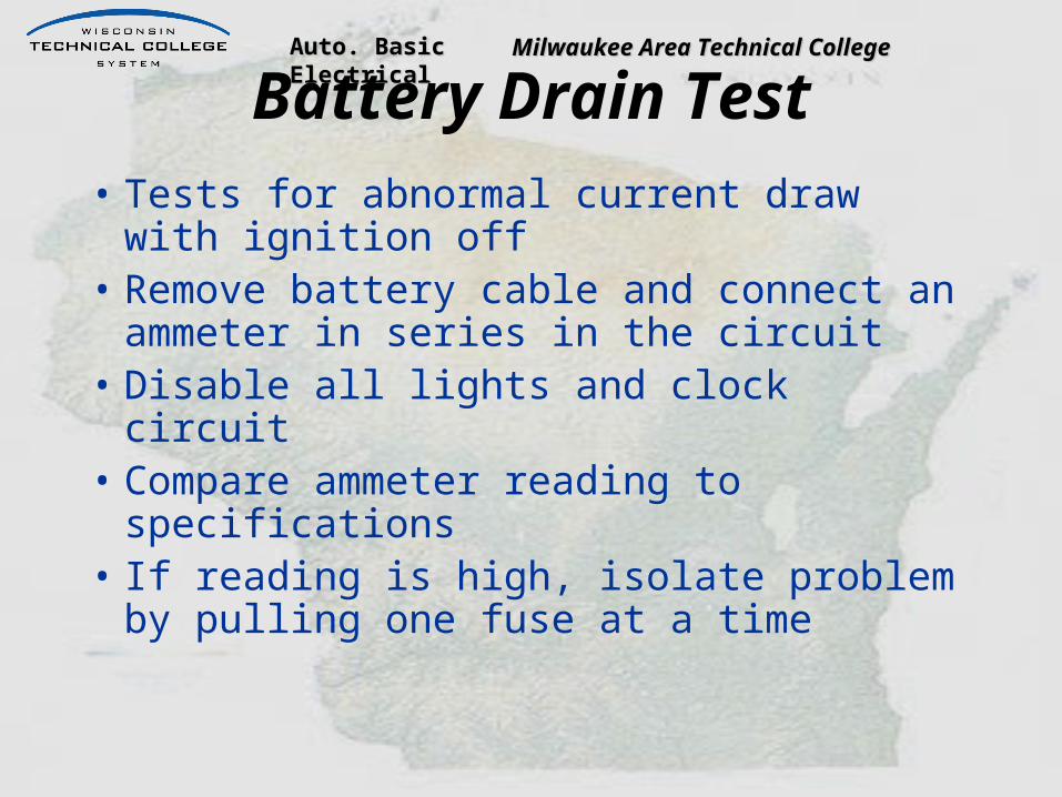
Battery Drain Test• Tests for abnormal current draw with
ignition off• Remove battery cable and connect an
ammeter in series in the circuit• Disable all lights and clock circuit• Compare ammeter reading to
specifications• If reading is high, isolate problem by
pulling one fuse at a time
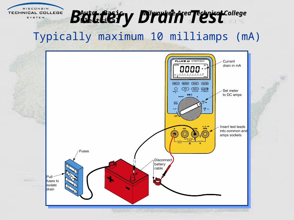
Auto. Basic Electrical Auto. Basic Electrical Milwaukee Area Technical CollegeMilwaukee Area Technical CollegeBattery Drain TestTypically maximum 10 milliamps (mA)
Auto. Basic Electrical Auto. Basic Electrical Milwaukee Area Technical CollegeMilwaukee Area Technical College
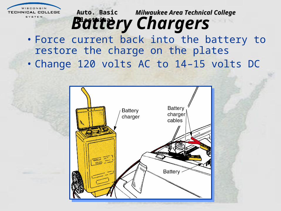
Battery Chargers• Force current back into the battery to
restore the charge on the plates• Change 120 volts AC to 14–15 volts DC

Auto. Basic Electrical Auto. Basic Electrical Milwaukee Area Technical CollegeMilwaukee Area Technical College
Slow Charger
• Often called a trickle charger• Feeds a small amount of current into
battery• Best for long term battery service• Typical slow charge is about 12 hours
at 10 amperes
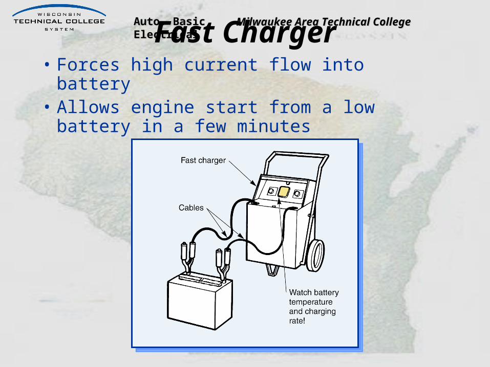
Auto. Basic Electrical Auto. Basic Electrical Milwaukee Area Technical CollegeMilwaukee Area Technical CollegeFast Charger• Forces high current flow into battery• Allows engine start from a low battery in
a few minutes
Auto. Basic Electrical Auto. Basic Electrical Milwaukee Area Technical CollegeMilwaukee Area Technical College
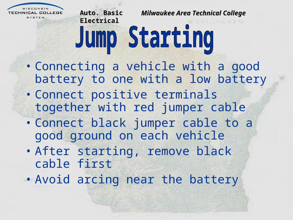
• Connecting a vehicle with a good battery to one with a low battery
• Connect positive terminals together with red jumper cable
• Connect black jumper cable to a good ground on each vehicle
• After starting, remove black cable first• Avoid arcing near the battery

Auto. Basic Electrical Auto. Basic Electrical Milwaukee Area Technical CollegeMilwaukee Area Technical College
Jumper Cable ConnectionRun the engine in the vehicle with the live
battery while cranking the other one

Auto. Basic Electrical Auto. Basic Electrical Milwaukee Area Technical CollegeMilwaukee Area Technical College
• Measures the current output under load• Determines actual battery performance• Used on batteries with open circuit
voltage of 12.4 volts or higher

Auto. Basic Electrical Auto. Basic Electrical Milwaukee Area Technical CollegeMilwaukee Area Technical College
Load TesterThe most accurate
method of determining battery condition

Auto. Basic Electrical Auto. Basic Electrical Milwaukee Area Technical CollegeMilwaukee Area Technical College
Determining Load
• Three times the amp-hour rating– 60 amp-hour battery– 60 x 3 = 180 amperes
• One half the cold crank rating– 400 CCA– 400 ÷ 2 = 200 amperes

Auto. Basic Electrical Auto. Basic Electrical Milwaukee Area Technical CollegeMilwaukee Area Technical College
Loading the Battery
• Turn the load control knob until the ammeter reads the correct amperage
• Maintain load for 15 seconds• Read the voltmeter at 15 seconds• Minimum 9.5 volts at room temperature

Auto. Basic Electrical Auto. Basic Electrical Milwaukee Area Technical CollegeMilwaukee Area Technical College
Load Test ResultsIf the reading is below the voltage in the
chart, the battery is probably bad

Auto. Basic Electrical Auto. Basic Electrical Milwaukee Area Technical CollegeMilwaukee Area Technical College 139
Micro-Type Testers• The new standard for batter
y testing (Click for L.O.)• Required by many OEM for
warranty• Uses conductance (the
ability to conduct current) to measure battery condition
• The battery does not need to be fully charged to test.

Auto. Basic Electrical Auto. Basic Electrical Milwaukee Area Technical CollegeMilwaukee Area Technical College
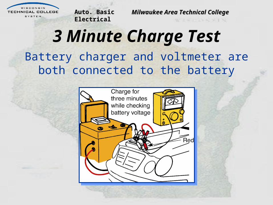
3 Minute Charge Test• Determines if the battery is sulphated• Performed if battery is in low state of
charge• Charge for 3 minutes at 30-40 amperes• Test voltage while charging• If the voltage goes above 15.5 volts,
battery should be replaced
Auto. Basic Electrical Auto. Basic Electrical Milwaukee Area Technical CollegeMilwaukee Area Technical College
3 Minute Charge TestBattery charger and voltmeter are both
connected to the battery


![{[Na1([mu]-H2O)Na2]2[(C2O4)2Cr([mu]-OH)2Cr(C2O4)2].H2O}n](https://img.pdfslide.net/doc/110x75/6286c8893ec30b1b0334325b/na1mu-h2ona22c2o42crmu-oh2crc2o42h2on-.jpg)