Embed Size (px)
Citation preview

8 Channel Power Amplifier
MM8003
ENGLISHFRANÇAIS
MM8003_U_00_cover.indd 3MM8003_U_00_cover.indd 3 08.4.28 2:19:35 PM08.4.28 2:19:35 PM
CAUTIONRISK OF ELECTRIC SHOCK
DO NOT OPEN
CAUTION: TO REDUCE THE RISK OF ELECTRIC SHOCK, DO NOT REMOVE COVER (OR BACK)
NO USER-SERVICEABLE PARTS INSIDE REFER SERVICING TO QUALIFIED SERVICE PERSONNEL
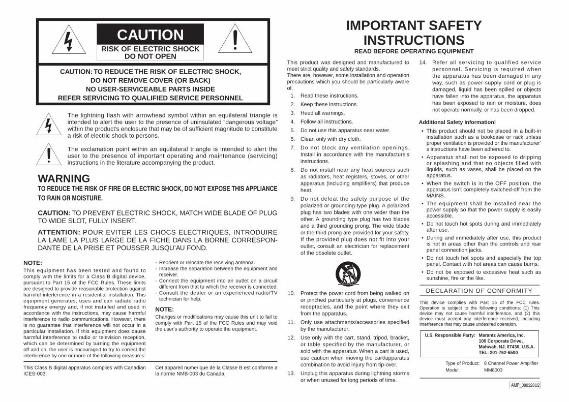
The lightning flash with arrowhead symbol within an equilateral triangle is intended to alert the user to the presence of uninsulated “dangerous voltage” within the product’s enclosure that may be of suffi cient magnitude to constitute a risk of electric shock to persons.
The exclamation point within an equilateral triangle is intended to alert the user to the presence of important operating and maintenance (servicing) instructions in the literature accompanying the product.
WARNINGTO REDUCE THE RISK OF FIRE OR ELECTRIC SHOCK, DO NOT EXPOSE THIS APPLIANCE TO RAIN OR MOISTURE.
CAUTION: TO PREVENT ELECTRIC SHOCK, MATCH WIDE BLADE OF PLUG TO WIDE SLOT, FULLY INSERT.
ATTENTION: POUR EVITER LES CHOCS ELECTRIQUES, INTRODUIRE LA LAME LA PLUS LARGE DE LA FICHE DANS LA BORNE CORRESPON-DANTE DE LA PRISE ET POUSSER JUSQU’AU FOND.
IMPORTANT SAFETY INSTRUCTIONS
READ BEFORE OPERATING EQUIPMENT
This product was designed and manufactured to meet strict quality and safety standards. There are, however, some installation and operation precautions which you should be particularly aware of. 1. Read these instructions.
2. Keep these instructions.
3. Heed all warnings.
4. Follow all instructions.
5. Do not use this apparatus near water.
6. Clean only with dry cloth.
7. Do not block any venti lat ion openings. Install in accordance with the manufacture's instructions.
8. Do not install near any heat sources such as radiators, heat registers, stoves, or other apparatus (including amplifi ers) that produce heat.
9. Do not defeat the safety purpose of the polarized or grounding-type plug. A polarized plug has two blades with one wider than the other. A grounding type plug has two blades and a third grounding prong. The wide blade or the third prong are provided for your safety. If the provided plug does not fit into your outlet, consult an electrician for replacement of the obsolete outlet.
10. Protect the power cord from being walked on or pinched particularly at plugs, convenience receptacles, and the point where they exit from the apparatus.
11. Only use attachments/accessories specifi ed by the manufacturer.
12. Use only with the cart, stand, tripod, bracket, or table specified by the manufacturer, or sold with the apparatus. When a cart is used, use caution when moving the cart/apparatus combination to avoid injury from tip-over.
13. Unplug this apparatus during lightning storms or when unused for long periods of time.
AMP_080328U2
NOTE:This equipment has been tested and found to comply with the limits for a Class B digital device, pursuant to Part 15 of the FCC Rules. These limits are designed to provide reasonable protection against harmful interference in a residential installation. This equipment generates, uses and can radiate radio frequency energy and, if not installed and used in accordance with the instructions, may cause harmful interference to radio communications. However, there is no guarantee that interference will not occur in a particular installation. If this equipment does cause harmful interference to radio or television reception, which can be determined by turning the equipment off and on, the user is encouraged to try to correct the interference by one or more of the following measures:
- Reorient or relocate the receiving antenna.- Increase the separation between the equipment and
receiver.- Connect the equipment into an outlet on a circuit
different from that to which the receiver is connected.- Consult the dealer or an experienced radio/TV
technician for help.
NOTE:Changes or modifi cations may cause this unit to fail to comply with Part 15 of the FCC Rules and may void the user's authority to operate the equipment.
This Class B digital apparatus complies with Canadian ICES-003.
Cet appareil numerique de la Classe B est conforme a la norme NMB-003 du Canada.
14. Refer al l servicing to quali f ied service personnel. Servicing is required when the apparatus has been damaged in any way, such as power-supply cord or plug is damaged, liquid has been spilled or objects have fallen into the apparatus, the apparatus has been exposed to rain or moisture, does not operate normally, or has been dropped.
Additional Safety Information!
• This product should not be placed in a built-in installation such as a bookcase or rack unless proper ventilation is provided or the manufacturer’s instructions have been adhered to.
• Apparatus shall not be exposed to dripping or splashing and that no objects filled with liquids, such as vases, shall be placed on the apparatus.
• When the switch is in the OFF position, the apparatus isn’t completely switched-off from the MAINS.
• The equipment shall be installed near the power supply so that the power supply is easily accessible.
• Do not touch hot spots during and immediately after use.
• During and immediately after use, this product is hot in areas other than the controls and rear panel connection jacks.
• Do not touch hot spots and especially the top panel. Contact with hot areas can cause burns.
• Do not be exposed to excessive heat such as sunshine, fi re or the like.
DECLARATION OF CONFORMITY
U.S. Responsible Party: Marantz America, Inc.100 Corporate Drive,Mahwah, NJ, 07430, U.S.A.TEL: 201-762-6500
Type of Product: Model:
8 Channel Power AmplifierMM8003
This device complies with Part 15 of the FCC rules. Operation is subject to the following conditions: (1) This device may not cause harmful interference, and (2) this device must accept any interference received, including interference that may cause undesired operation.
MM8003_U_00_cover.indd 4MM8003_U_00_cover.indd 4 08.4.28 2:19:35 PM08.4.28 2:19:35 PM
BA
SIC
CON
NEC
TIO
NS
OPE
RATI
ON
AD
VAN
CED
CO
NN
ECTI
ON
STR
OUBL
ESHO
OTIN
GO
THER
SN
AM
ES A
ND
FU
NCT
ION
ENGLISH
1
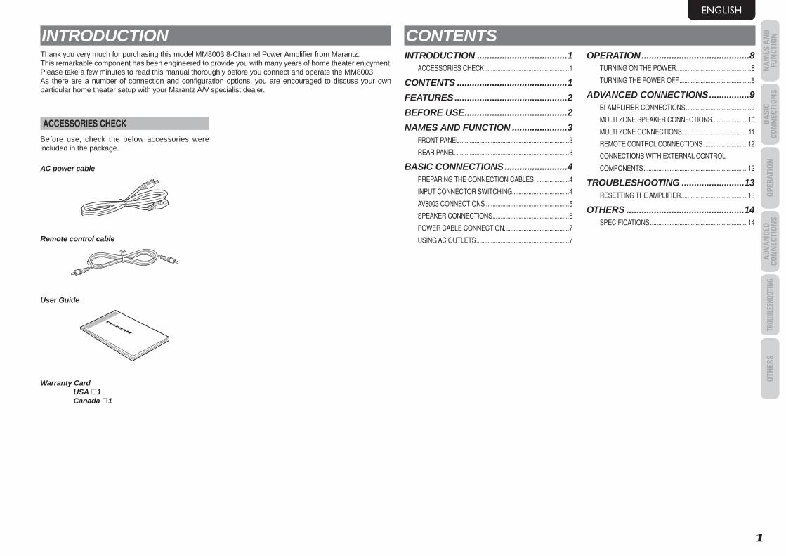
INTRODUCTIONThank you very much for purchasing this model MM8003 8-Channel Power Amplifi er from Marantz. This remarkable component has been engineered to provide you with many years of home theater enjoyment. Please take a few minutes to read this manual thoroughly before you connect and operate the MM8003. As there are a number of connection and confi guration options, you are encouraged to discuss your own particular home theater setup with your Marantz A/V specialist dealer.
ACCESSORIES CHECK
Before use, check the below accessories were included in the package.
AC power cable
Remote control cable
User Guide
Warranty CardUSA × 1Canada × 1
CONTENTSINTRODUCTION ....................................1
ACCESSORIES CHECK ....................................................1
CONTENTS ............................................1
FEATURES .............................................2
BEFORE USE .........................................2
NAMES AND FUNCTION ......................3FRONT PANEL ...................................................................3
REAR PANEL .....................................................................3
BASIC CONNECTIONS .........................4PREPARING THE CONNECTION CABLES ....................4
INPUT CONNECTOR SWITCHING...................................4
AV8003 CONNECTIONS ...................................................5
SPEAKER CONNECTIONS ...............................................6
POWER CABLE CONNECTION........................................7
USING AC OUTLETS .........................................................7
OPERATION ...........................................8TURNING ON THE POWER ..............................................8
TURNING THE POWER OFF ............................................8
ADVANCED CONNECTIONS ................9BI-AMPLIFIER CONNECTIONS ........................................9
MULTI ZONE SPEAKER CONNECTIONS ......................10
MULTI ZONE CONNECTIONS ........................................11
REMOTE CONTROL CONNECTIONS ...........................12
CONNECTIONS WITH EXTERNAL CONTROL
COMPONENTS ................................................................12
TROUBLESHOOTING .........................13RESETTING THE AMPLIFIER .........................................13
OTHERS ...............................................14SPECIFICATIONS ............................................................14
MM8003_U_01_ENG.indd 1MM8003_U_01_ENG.indd 1 08.4.28 2:19:56 PM08.4.28 2:19:56 PM
ENGLISH
2
FEATURESThis 8-channel power amplifi er comes with upgraded functions and supports the latest format of surround sound without compromising the design technology of Marantz's fl agship models.
Current feedback type of discrete power amplifi er with high sound qualityThe MM8003 features in all 8 channels the current feedback type of power amplifi er, which uses the complementary push-pull circuitry incorporated in Marantz's SM-11S1 Hi-Fi Power Amplifier. This improves the model's operating stability and enables it to achieve high-density, high-speed sound reproduction across a wide sound range.In the rear section the power amplifi er is a current/voltage conversion amplifier unit that employs a Wilson current mirror circuit for amplifying sound up to the treble range at low distortion levels.
Improved instantaneous current supply capabilityIn the rear section of the power amplifier is the LAPT (high-performance power transistor), which is featured in Marantz's model SM-11S1 Hi-Fi Power Amplifi er. This device improves the instantaneous current supply capability.Copper bus bars are featured in the unit that supplies the power to each channel.The power supply unit has a large toroidal transformer that delivers low levels of noise and leakage fl ux thanks to its internal structural features such as its laminated core, silicon steel-plated core ring,etc., and the use of its shielded casing.Original Marantz parts with a combined capacitance of 100,000 µF (50,000µF/71V × 2), which have been specially crafted to achieve the maximum in terms of sound quality, are employed in the block capacitor, a key component of the power supply unit.Thanks to the improvements in the current supply capability of these parts, you can enjoy high-powered sound brimming with ambiance.
High-sound-quality design based on the pure surround conceptA chimney-type heat sink and extremely quiet cooling fan deal with the heat that is discharged from the 8-channel amplifi er to a high degree of effi ciency. A high-precision temperature sensor IC is used to adjust the rotational speed of the cooling fan in response to the changes in the amount of heat generated by the amplifi er.These features together make for lavish specifi cations well suited to the amplifi er's use in high-end theater systems, which are engineered to ensure virtually noiseless operation.The amplifi er's chassis is copper-plated to protect the analog audio circuitry from high-frequency noise. This is an important technological aspect for reproducing sound without compromising the delicately nuanced sound fi elds of Super Audio.In addition, top-of-the-line audio capacitors, film capacitors and other high-quality components are used to achieve a high-sound-quality design.
BALANCED/UNBALANCED switching functionThis function makes it possible to select BALANCED or UNBALANCED input each channel depending on the application.
Remote power controlBy connecting the amplifier to Marantz's model AV8003 AV pre-tuner, the amplifi er's power can be switched on or off in tandem with the power on/off operation of the AV8003 using the remote power control function.A fl oating ground connection that doesn’t form a ground loop is used for the connection with the AV8003 so the sound quality is not adversely affected.
Other functionsAlso provided are an IR fl asher input connector to support customized installation, and DC trigger input connector and output connectors.
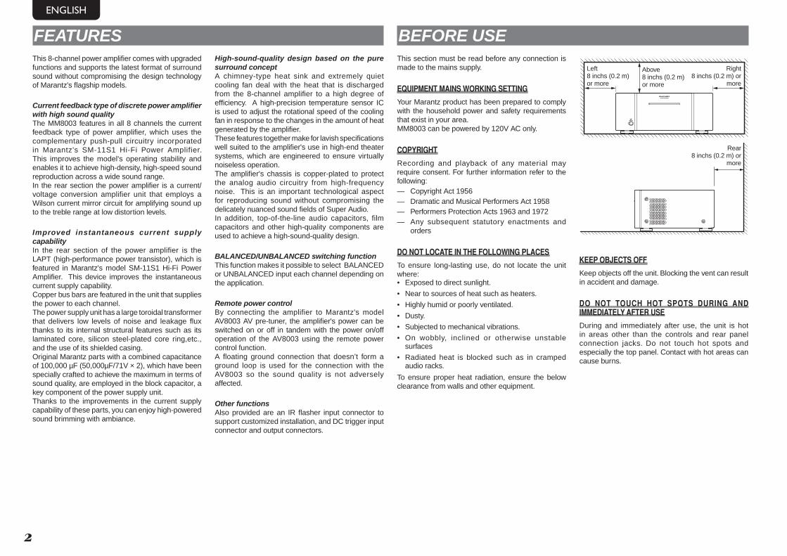
BEFORE USEThis section must be read before any connection is made to the mains supply.
EQUIPMENT MAINS WORKING SETTING
Your Marantz product has been prepared to comply with the household power and safety requirements that exist in your area.MM8003 can be powered by 120V AC only.
COPYRIGHT
Recording and playback of any material may require consent. For further information refer to the following:— Copyright Act 1956— Dramatic and Musical Performers Act 1958— Performers Protection Acts 1963 and 1972— Any subsequent statutory enactments and
orders
DO NOT LOCATE IN THE FOLLOWING PLACES
To ensure long-lasting use, do not locate the unit where:• Exposed to direct sunlight.
• Near to sources of heat such as heaters.
• Highly humid or poorly ventilated.
• Dusty.
• Subjected to mechanical vibrations.
• On wobbly, inclined or otherwise unstable surfaces
• Radiated heat is blocked such as in cramped audio racks.
To ensure proper heat radiation, ensure the below clearance from walls and other equipment.
8CH POWER AMPLIFIER MM80038CH POWER AMPLIFIER MM8003
POWER ON/OFFPOWER ON/OFF
STANDBYSTANDBY
Above8 inchs (0.2 m) or more
Left8 inchs (0.2 m) or more
Right8 inchs (0.2 m) or
more
Rear8 inchs (0.2 m) or
more
KEEP OBJECTS OFF
Keep objects off the unit. Blocking the vent can result in accident and damage.
DO NOT TOUCH HOT SPOTS DURING AND IMMEDIATELY AFTER USE
During and immediately after use, the unit is hot in areas other than the controls and rear panel connection jacks. Do not touch hot spots and especially the top panel. Contact with hot areas can cause burns.
MM8003_U_01_ENG.indd 2MM8003_U_01_ENG.indd 2 08.4.28 2:19:57 PM08.4.28 2:19:57 PM
ENGLISH
BA
SIC
CON
NEC
TIO
NS
OPE
RATI
ON
AD
VAN
CED
CO
NN
ECTI
ON
STR
OUBL
ESHO
OTIN
GO
THER
SN
AM
ES A
ND
FU
NCT
ION
NA
MES
AN
D
FUN
CTIO
N
3
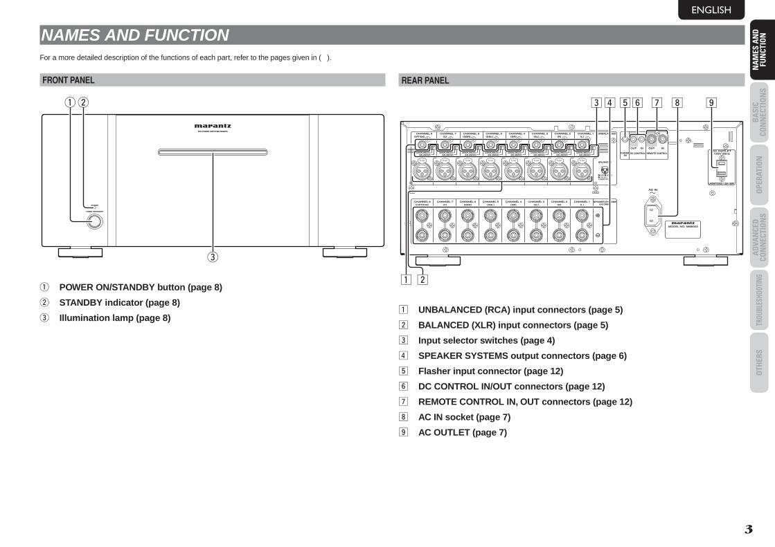
NAMES AND FUNCTIONFor a more detailed description of the functions of each part, refer to the pages given in ( ).
FRONT PANEL
8CH POWER AMPLIFIER MM80038CH POWER AMPLIFIER MM8003
POWER ON/STANDBYPOWER ON/STANDBY
STANDBYSTANDBY
qw
e
q POWER ON/STANDBY button (page 8)
w STANDBY indicator (page 8)
e Illumination lamp (page 8)
REAR PANEL
120V 60Hz120V 60Hz
UNSWITCHED 1.25A 150WUNSWITCHED 1.25A 150W
AC OUTLETAC OUTLETDC CONTROLDC CONTROL
ININFLASHERFLASHER REMOTE CONTROLREMOTE CONTROL
SPEAKER SYSTEMSSPEAKER SYSTEMS6-8 OHMS6-8 OHMS
AC INAC IN
123
CONNECTION
GND HOT(+)COLD(-)3
21
BALANCEDBALANCEDUNBALANCEDUNBALANCED
BALANCEDBALANCED
UNBALANCEDUNBALANCED
BALANCEDBALANCEDUNBALANCEDUNBALANCED
BALANCEDBALANCEDUNBALANCEDUNBALANCED
BALANCEDBALANCEDUNBALANCEDUNBALANCED
BALANCEDBALANCEDUNBALANCEDUNBALANCED
BALANCEDBALANCEDUNBALANCEDUNBALANCED
BALANCEDBALANCEDUNBALANCEDUNBALANCED
BALANCEDBALANCEDUNBALANCEDUNBALANCED
MODEL NO. MM8003MODEL NO. MM8003
OUTOUT OUTOUT ININ
CHANNEL 1CHANNEL 1CHANNEL 2CHANNEL 2CHANNEL 3CHANNEL 3CHANNEL 4CHANNEL 4CHANNEL 5CHANNEL 5CHANNEL 6CHANNEL 6CHANNEL 7CHANNEL 7CHANNEL 8CHANNEL 8
CHANNEL 1CHANNEL 1CHANNEL 2CHANNEL 2CHANNEL 3CHANNEL 3CHANNEL 4CHANNEL 4CHANNEL 5CHANNEL 5CHANNEL 6CHANNEL 6CHANNEL 7CHANNEL 7CHANNEL 8CHANNEL 8
ININ
((LL))((RR))((SLSL))((SRSR))((SBLSBL))((SBRSBR))((CC))((OPTIONOPTION))
((LL))((RR))((SLSL))((SRSR))((SBLSBL))((SBRSBR))((CC))((OPTIONOPTION))
PUSH PUSH PUSH PUSH PUSH PUSH PUSH PUSH
z
c bnv ,
x
m .
z UNBALANCED (RCA) input connectors (page 5)
x BALANCED (XLR) input connectors (page 5)
c Input selector switches (page 4)
v SPEAKER SYSTEMS output connectors (page 6)
b Flasher input connector (page 12)
n DC CONTROL IN/OUT connectors (page 12)
m REMOTE CONTROL IN, OUT connectors (page 12)
, AC IN socket (page 7)
. AC OUTLET (page 7)
MM8003_U_01_ENG.indd 3MM8003_U_01_ENG.indd 3 08.4.28 2:19:57 PM08.4.28 2:19:57 PM
ENGLISH
BA
SIC CO
NN
ECTION
SO
PERATION
AD
VAN
CED
CON
NECTIO
NS
TROUBLESHOOTINGO
THERS
NA
MES A
ND
FU
NCTIO
NB
ASIC
CON
NECTIO
NS
4
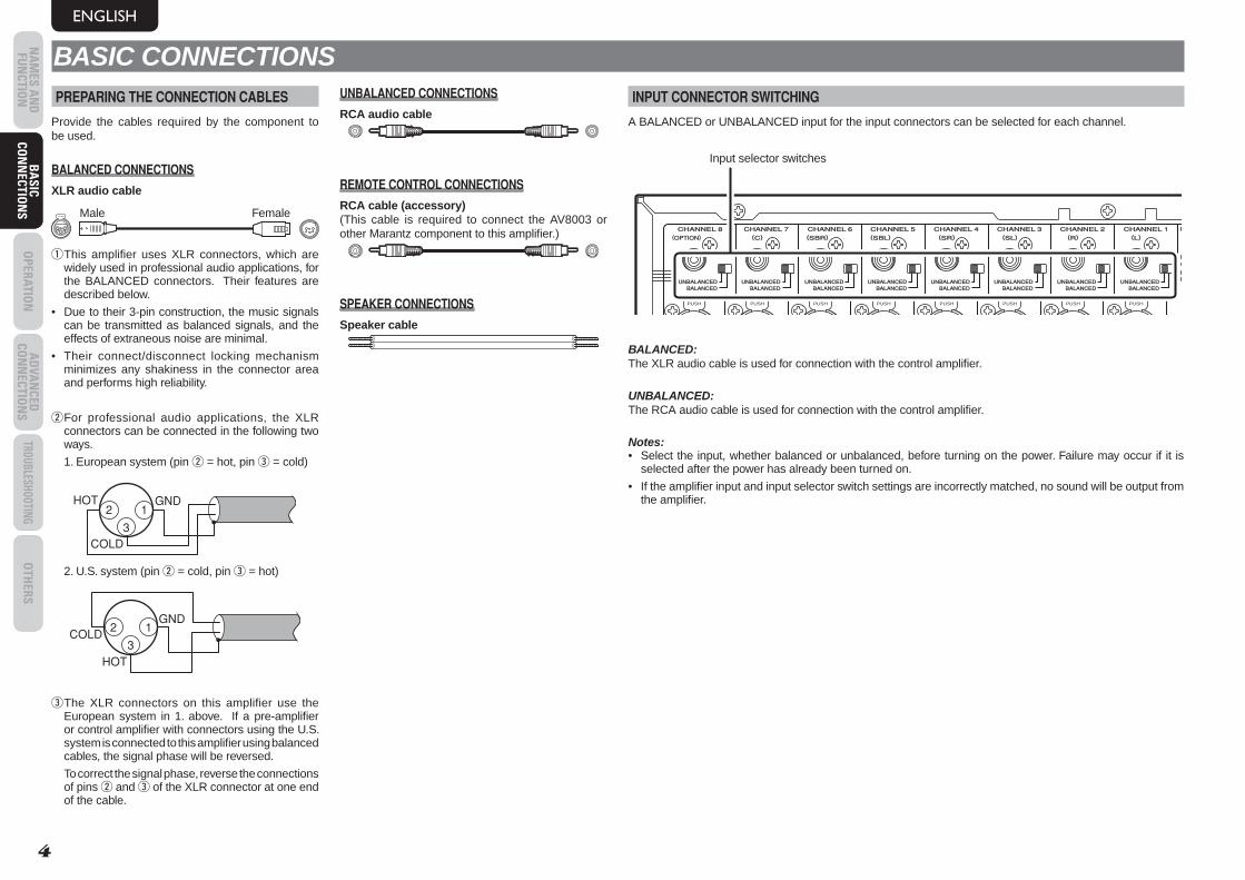
BASIC CONNECTIONSPREPARING THE CONNECTION CABLES
Provide the cables required by the component to be used.
BALANCED CONNECTIONS
XLR audio cable
1
3
12
PUSH
3
1 2
Male Female
q This amplifi er uses XLR connectors, which are widely used in professional audio applications, for the BALANCED connectors. Their features are described below.
• Due to their 3-pin construction, the music signals can be transmitted as balanced signals, and the effects of extraneous noise are minimal.
• Their connect/disconnect locking mechanism minimizes any shakiness in the connector area and performs high reliability.
w For professional audio applications, the XLR connectors can be connected in the following two ways.
1. European system (pin w = hot, pin e = cold)
2 1 3
GND
COLD
HOT
2. U.S. system (pin w = cold, pin e = hot)
2 1 3
HOT
GND COLD
e The XLR connectors on this amplifier use the European system in 1. above. If a pre-amplifi er or control amplifi er with connectors using the U.S. system is connected to this amplifi er using balanced cables, the signal phase will be reversed.
To correct the signal phase, reverse the connections of pins w and e of the XLR connector at one end of the cable.
UNBALANCED CONNECTIONS
RCA audio cable
REMOTE CONTROL CONNECTIONS
RCA cable (accessory)(This cable is required to connect the AV8003 or other Marantz component to this amplifi er.)
SPEAKER CONNECTIONS
Speaker cable
INPUT CONNECTOR SWITCHING
A BALANCED or UNBALANCED input for the input connectors can be selected for each channel.
BALANCEDBALANCEDUNBALANCEDUNBALANCED
BBALANCED
UUNBALANCED
BALANCEDBALANCEDUNBALANCEDUNBALANCED
BALANCEDBALANCEDUNBALANCEDUNBALANCED
BALANCEDBALANCEDUNBALANCEDUNBALANCED
BALANCEDBALANCEDUNBALANCEDUNBALANCED
BALANCEDBALANCEDUNBALANCEDUNBALANCED
BALANCEDBALANCEDUNBALANCEDUNBALANCED
BALANCEDBALANCEDUNBALANCEDUNBALANCED
CHANNEL 1CHANNEL 1CHANNEL 2CHANNEL 2CHANNEL 3CHANNEL 3CHANNEL 4CHANNEL 4CHANNEL 5CHANNEL 5CHANNEL 6CHANNEL 6CHANNEL 7CHANNEL 7CHANNEL 8CHANNEL 8((LL))((RR))((SLSL))((SRSR))((SBLSBL))((SBRSBR))((CC))((OPTIONOPTION))
PUSH PUSH PUSH PUSH PUSH PUSH PUSH PUSH
Input selector switches
BALANCED: The XLR audio cable is used for connection with the control amplifi er.
UNBALANCED: The RCA audio cable is used for connection with the control amplifi er.
Notes:• Select the input, whether balanced or unbalanced, before turning on the power. Failure may occur if it is
selected after the power has already been turned on.
• If the amplifi er input and input selector switch settings are incorrectly matched, no sound will be output from the amplifi er.
MM8003_U_01_ENG.indd 4MM8003_U_01_ENG.indd 4 08.4.28 2:19:57 PM08.4.28 2:19:57 PM
ENGLISH
BA
SIC
CON
NEC
TIO
NS
OPE
RATI
ON
AD
VAN
CED
CO
NN
ECTI
ON
STR
OUBL
ESHO
OTIN
GO
THER
SN
AM
ES A
ND
FU
NCT
ION
BA
SIC
CON
NEC
TIO
NS
5
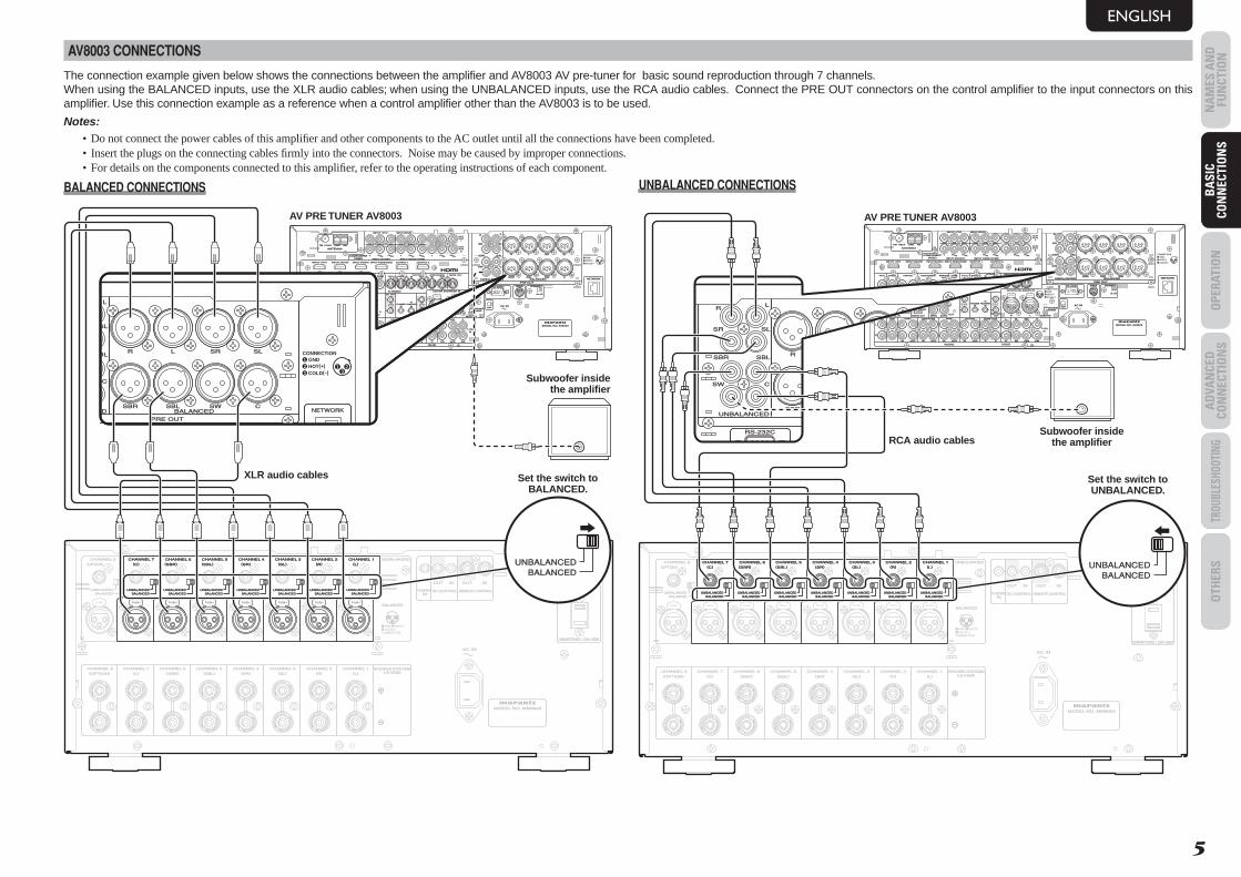
AV8003 CONNECTIONS
The connection example given below shows the connections between the amplifi er and AV8003 AV pre-tuner for basic sound reproduction through 7 channels.When using the BALANCED inputs, use the XLR audio cables; when using the UNBALANCED inputs, use the RCA audio cables. Connect the PRE OUT connectors on the control amplifi er to the input connectors on this amplifi er. Use this connection example as a reference when a control amplifi er other than the AV8003 is to be used.
Notes:• Do not connect the power cables of this amplifi er and other components to the AC outlet until all the connections have been completed.• Insert the plugs on the connecting cables fi rmly into the connectors. Noise may be caused by improper connections.• For details on the components connected to this amplifi er, refer to the operating instructions of each component.
BALANCED CONNECTIONS
DC CONTROLDC CONTROLININ
FLASHERFLASHER REMOTE CONTROLREMOTE CONTROL
SPEAKER SYSTEMSSPEAKER SYSTEMS6-8 OHMS6-8 OHMS
AC INAC IN
123
CONNECTION
GND HOT(+)COLD(-)3
21
BALANCEDBALANCEDUNBALANCEDUNBALANCED
BALANCEDBALANCED
UNBALANCEDUNBALANCED
BALANCEDBALANCEDUNBALANCEDUNBALANCED
BALANCEDBALANCEDUNBALANCEDUNBALANCED
BALANCEDBALANCEDUNBALANCEDUNBALANCED
BALANCEDBALANCEDUNBALANCEDUNBALANCED
BALANCEDBALANCEDUNBALANCEDUNBALANCED
BALANCEDBALANCEDUNBALANCEDUNBALANCED
BALANCEDBALANCEDUNBALANCEDUNBALANCED
MODEL NO. MM8003MODEL NO. MM8003
OUTOUT OUTOUT ININ
CHANNEL 1CHANNEL 1CHANNEL 2CHANNEL 2CHANNEL 3CHANNEL 3CHANNEL 4CHANNEL 4CHANNEL 5CHANNEL 5CHANNEL 6CHANNEL 6CHANNEL 7CHANNEL 7CHANNEL 8CHANNEL 8
CHANNEL 1CHANNEL 1CHANNEL 2CHANNEL 2CHANNEL 3CHANNEL 3CHANNEL 4CHANNEL 4CHANNEL 5CHANNEL 5CHANNEL 6CHANNEL 6CHANNEL 7CHANNEL 7CHANNEL 8CHANNEL 8
ININ
((LL))((RR))((SLSL))((SRSR))((SBLSBL))((SBRSBR))((CC))((OPTIONOPTION))
((LL))((RR))((SLSL))((SRSR))((SBLSBL))((SBRSBR))((CC))((OPTIONOPTION))
PUSH PUSH PUSH PUSH PUSH PUSH PUSH PUSH
120V 60Hz120V 60Hz
UNSWITCHED 1.25A 150WUNSWITCHED 1.25A 150W
AC OUTLETAC OUTLET
BALANCEDBALANCEDUNBALANCEDUNBALANCED
BALANCEDBALANCEDUNBALANCEDUNBALANCED
BALANCEDBALANCEDUNBALANCEDUNBALANCED
BALANCEDBALANCEDUNBALANCEDUNBALANCED
BALANCEDBALANCEDUNBALANCEDUNBALANCED
BALANCEDBALANCEDUNBALANCEDUNBALANCED
PUSH PUSH PUSH PUSH PUSH PUSH
CHANNEL 2CHANNEL 2CHANNEL 3CHANNEL 3CHANNEL 4CHANNEL 4CHANNEL 5CHANNEL 5CHANNEL 6CHANNEL 6CHANNEL 7CHANNEL 7((RR))((SLSL))((SRSR))((SBLSBL))((SBRSBR))((CC))
CHANNEL 1CHANNEL 1((LL))
BALANCEDBALANCEDUNBALANCEDUNBALANCED
PUSH
LL SRSR SLSLRR
RR
SRSR SLSL
SWSW CC
SBRSBR SBLSBL
LL
SBLSBL SWSW CCSBRSBR
FM FM ((7575ΩΩ)) GNDGND AMAM
ANTENNAANTENNA
OUTOUTPUTPUT
11
OUTOUTPUTPUT
22
INPUT 3INPUT 3((VCR1VCR1)) OUTPUT 1OUTPUT 1 OUTPUT 2OUTPUT 2INPUT 1INPUT 1((TVTV)) INPUT 4INPUT 4((DSS/VCR2DSS/VCR2))INPUT 2INPUT 2((DVDDVD))
COMPONENTCOMPONENTVIDEOVIDEO
CCBB//PPBBCCRR//PPRR
CCRR//PPRRCCRR//PPRR
CCBB//PPBBCCBB//PPBBYY YYYY
INPUT 1INPUT 1((TVTV))
INPUT 4INPUT 4((DSSDSS // VCR2VCR2))INPUT 3INPUT 3((VCR1VCR1))
INPUT 2INPUT 2((DVDDVD))
RS-232CRS-232C SPEAKER CSPEAKER CSIRIUSSIRIUS
NETWORKNETWORK
ONON OFFOFF
13
CONNECTIONGNDHOT(+)COLD(-)3
21
2
AC INAC IN
OUTOUTININ ININOUTOUTVIDEOVIDEO
MONITORMONITOROUTOUT
DVDDVD((22)) DSS/VCR2DSS/VCR2((44))TVTV((11)) ZONEZONEOUTOUT
VCR1VCR1((33)) DVDDVD((22))TVTV((11))
22
11
FLASHERFLASHERININ
IRIRRECEIVERRECEIVER
ININ
66 COAX.COAX.5544
OUTOUT
ININ 11
22
EMITTEREMITTER OUT OUT SELECTORSELECTOR
DC OUTDC OUT
RR LL
OUTOUT
RR
OUTOUT
LLTAPETAPE
OUTOUTININ RROUTOUT
LL
DSS/VCR2DSS/VCR2
AUDIOAUDIO
BALANCEDBALANCED
PRE OUTPRE OUT
UNBALANCEDUNBALANCED
TVTV
ININ SRSR
VCR1VCR1
ININ
DVDDVD SLSL
SBRSBR
SBLSBL
SWSW
CC
AA BB
7.1CH7.1CHININ
((AUXAUX))
332211 OPT.OPT.
MODEL NO. AV8003MODEL NO. AV8003
DIGITAL INDIGITAL IN DIGITAL OUTDIGITAL OUT MAINMAIN ZONEZONE
CD/CDRCD/CDR
ININ
REMOTEREMOTE 123
BALANCEDBALANCEDUNBALANCEDUNBALANCED
ININ OUTOUT
S-VIDEOS-VIDEO
ININ OUTOUTDSS/VCR2DSS/VCR2((44))VCR1VCR1((33)) MONI. OUTMONI. OUT
CD/CDR BALANCED INCD/CDR BALANCED IN
ZONE OUTZONE OUT
CONNECTIONGNDHOT(+)COLD(-)3
21
PUSH PUSH
LL SRSR SLSLRR
SLSL
CC
BLSBL
LL
SBLSBL SWSW CCSBRSBR
RS-232C
NETWORKNETWORK
13
CONNECTIONGNDHOT(+)COLD(-)3
21
2
BALANCEDBALANCEDEDUNBALANCED
SPEAKER C
PRE OUTPRE OUT
BALANCEDBALANCEDUNBALANCEDUNBALANCED
AV PRE TUNER AV8003
Set the switch to BALANCED.
XLR audio cables
Subwoofer inside the amplifi er
UNBALANCED CONNECTIONS
DC CONTROLDC CONTROLININ
FLASHERFLASHER REMOTE CONTROLREMOTE CONTROL
SPEAKER SYSTEMSSPEAKER SYSTEMS6-8 OHMS6-8 OHMS
AC INAC IN
123
CONNECTION
GND HOT(+)COLD(-)3
21
BALANCEDBALANCEDUNBALANCEDUNBALANCED
BALANCEDBALANCED
UNBALANCEDUNBALANCED
BALANCEDBALANCEDUNBALANCEDUNBALANCED
BALANCEDBALANCEDUNBALANCEDUNBALANCED
BALANCEDBALANCEDUNBALANCEDUNBALANCED
BALANCEDBALANCEDUNBALANCEDUNBALANCED
BALANCEDBALANCEDUNBALANCEDUNBALANCED
BALANCEDBALANCEDUNBALANCEDUNBALANCED
BALANCEDBALANCEDUNBALANCEDUNBALANCED
MODEL NO. MM8003MODEL NO. MM8003
OUTOUT OUTOUT ININ
CHANNEL 1CHANNEL 1CHANNEL 2CHANNEL 2CHANNEL 3CHANNEL 3CHANNEL 4CHANNEL 4CHANNEL 5CHANNEL 5CHANNEL 6CHANNEL 6CHANNEL 7CHANNEL 7CHANNEL 8CHANNEL 8
CHANNEL 1CHANNEL 1CHANNEL 2CHANNEL 2CHANNEL 3CHANNEL 3CHANNEL 4CHANNEL 4CHANNEL 5CHANNEL 5CHANNEL 6CHANNEL 6CHANNEL 7CHANNEL 7CHANNEL 8CHANNEL 8
ININ
((LL))((RR))((SLSL))((SRSR))((SBLSBL))((SBRSBR))((CC))((OPTIONOPTION))
((LL))((RR))((SLSL))((SRSR))((SBLSBL))((SBRSBR))((CC))((OPTIONOPTION))
PUSH PUSH PUSH PUSH PUSH PUSH PUSH PUSH
120V 60Hz120V 60Hz
UNSWITCHED 1.25A 150WUNSWITCHED 1.25A 150W
AC OUTLETAC OUTLET
BALANCEDBALANCEDUNBALANCEDUNBALANCED
BALANCEDBALANCEDUNBALANCEDUNBALANCED
BALANCEDBALANCEDUNBALANCEDUNBALANCED
BALANCEDBALANCEDUNBALANCEDUNBALANCED
BALANCEDBALANCEDUNBALANCEDUNBALANCED
BALANCEDBALANCEDUNBALANCEDUNBALANCED
BALANCEDBALANCEDUNBALANCEDUNBALANCED
CHANNEL 1CHANNEL 1CHANNEL 2CHANNEL 2CHANNEL 3CHANNEL 3CHANNEL 4CHANNEL 4CHANNEL 5CHANNEL 5CHANNEL 6CHANNEL 6CHANNEL 7CHANNEL 7((LL))((RR))((SLSL))((SRSR))((SBLSBL))((SBRSBR))((CC))
LL SRSR SLSLRR
RR
SRSR SLSL
SWSW CC
SBRSBR SBLSBL
LL
SBLSBL SWSW CCSBRSBR
FM FM ((7575ΩΩ)) GNDGND AMAM
ANTENNAANTENNA
OUTOUTPUTPUT
11
OUTOUTPUTPUT
22
INPUT 3INPUT 3((VCR1VCR1)) OUTPUT 1OUTPUT 1 OUTPUT 2OUTPUT 2INPUT 1INPUT 1((TVTV)) INPUT 4INPUT 4((DSS/VCR2DSS/VCR2))INPUT 2INPUT 2((DVDDVD))
COMPONENTCOMPONENTVIDEOVIDEO
CCBB//PPBBCCRR//PPRR
CCRR//PPRRCCRR//PPRR
CCBB//PPBBCCBB//PPBBYY YYYY
INPUT 1INPUT 1((TVTV))
INPUT 4INPUT 4((DSSDSS // VCR2VCR2))INPUT 3INPUT 3((VCR1VCR1))
INPUT 2INPUT 2((DVDDVD))
RS-232CRS-232C SPEAKER CSPEAKER CSIRIUSSIRIUS
NETWORKNETWORK
ONON OFFOFF
13
CONNECTIONGNDHOT(+)COLD(-)3
21
2
AC INAC IN
OUTOUTININ ININOUTOUTVIDEOVIDEO
MONITORMONITOROUTOUT
DVDDVD((22)) DSS/VCR2DSS/VCR2((44))TVTV((11)) ZONEZONEOUTOUT
VCR1VCR1((33)) DVDDVD((22))TVTV((11))
22
11
FLASHERFLASHERININ
IRIRRECEIVERRECEIVER
ININ
66 COAX.COAX.5544
OUTOUT
ININ 11
22
EMITTEREMITTER OUT OUT SELECTORSELECTOR
DC OUTDC OUT
RR LL
OUTOUT
RR
OUTOUT
LLTAPETAPE
OUTOUTININ RROUTOUT
LL
DSS/VCR2DSS/VCR2
AUDIOAUDIO
BALANCEDBALANCED
PRE OUTPRE OUT
UNBALANCEDUNBALANCED
TVTV
ININ SRSR
VCR1VCR1
ININ
DVDDVD SLSL
SBRSBR
SBLSBL
SWSW
CC
AA BB
7.1CH7.1CHININ
((AUXAUX))
332211 OPT.OPT.
MODEL NO. AV8003MODEL NO. AV8003
DIGITAL INDIGITAL IN DIGITAL OUTDIGITAL OUT MAINMAIN ZONEZONE
CD/CDRCD/CDR
ININ
REMOTEREMOTE 123
BALANCEDBALANCEDUNBALANCEDUNBALANCED
ININ OUTOUT
S-VIDEOS-VIDEO
ININ OUTOUTDSS/VCR2DSS/VCR2((44))VCR1VCR1((33)) MONI. OUTMONI. OUT
CD/CDR BALANCED INCD/CDR BALANCED IN
ZONE OUTZONE OUT
CONNECTIONGNDHOT(+)COLD(-)3
21
PUSH PUSH
LL SRSR SLSLRR
RR
SRSR SLSL
SWSW CC
SBRSBR SBLSBL
LL
SBLSBL SWSW CCSBRSBR
RS-232CRS-232C
NETWORKNETWORK
13
CONNECTIONGNDHOT(+)COLD(-)3
21
2
BALANCEDBALANCEDUNBALANCEDUNBALANCED
SPEAKER CSPEAKER C
PRE OUTPRE OUT
3
1 2
3
1 2
3
1 2
3
1 2
3
1 2
3
1 2
BALANCEDBALANCEDUNBALANCEDUNBALANCED
Set the switch to UNBALANCED.
AV PRE TUNER AV8003
RCA audio cablesSubwoofer inside
the amplifi er
MM8003_U_01_ENG.indd 5MM8003_U_01_ENG.indd 5 08.4.28 2:19:57 PM08.4.28 2:19:57 PM
ENGLISH
BA
SIC CO
NN
ECTION
SO
PERATION
AD
VAN
CED
CON
NECTIO
NS
TROUBLESHOOTINGO
THERS
NA
MES A
ND
FU
NCTIO
NB
ASIC
CON
NECTIO
NS
6
SPEAKER CONNECTIONS
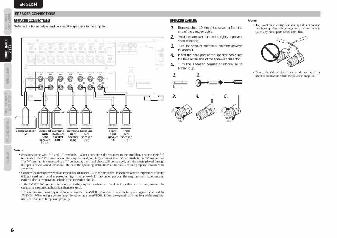
SPEAKER CONNECTIONS
Refer to the fi gure below, and connect the speakers to the amplifi er.
DC CONTROLDC CONTROLININ
FLASHERFLASHER REMOTE CONTROLREMOTE CONTROL
SPEAKER SYSTEMSSPEAKER SYSTEMS6-8 OHMS6-8 OHMS
AC INAC IN
123
CONNECTION
GND HOT(+)COLD(-)3
21
BALANCEDBALANCEDUNBALANCEDUNBALANCED
BALANCEDBALANCED
UNBALANCEDUNBALANCED
BALANCEDBALANCEDUNBALANCEDUNBALANCED
BALANCEDBALANCEDUNBALANCEDUNBALANCED
BALANCEDBALANCEDUNBALANCEDUNBALANCED
BALANCEDBALANCEDUNBALANCEDUNBALANCED
BALANCEDBALANCEDUNBALANCEDUNBALANCED
BALANCEDBALANCEDUNBALANCEDUNBALANCED
BALANCEDBALANCEDUNBALANCEDUNBALANCED
MODEL NO. MM8003MODEL NO. MM8003
OUTOUT OUTOUT ININ
CHANNEL 1CHANNEL 1CHANNEL 2CHANNEL 2CHANNEL 3CHANNEL 3CHANNEL 4CHANNEL 4CHANNEL 5CHANNEL 5CHANNEL 6CHANNEL 6CHANNEL 7CHANNEL 7CHANNEL 8CHANNEL 8
CHANNEL 1CHANNEL 1CHANNEL 2CHANNEL 2CHANNEL 3CHANNEL 3CHANNEL 4CHANNEL 4CHANNEL 5CHANNEL 5CHANNEL 6CHANNEL 6CHANNEL 7CHANNEL 7CHANNEL 8CHANNEL 8
ININ
((LL))((RR))((SLSL))((SRSR))((SBLSBL))((SBRSBR))((CC))((OPTIONOPTION))
((LL))((RR))((SLSL))((SRSR))((SBLSBL))((SBRSBR))((CC))((OPTIONOPTION))
PUSH PUSH PUSH PUSH PUSH PUSH PUSH PUSH
120V 60H120V 60Hz
UNSWITCHED 1.25AUNSWITCHED 1.25A 150W
AC OUTLEAC OUTLET
CHANNEL 1CHANNEL 1CHANNEL 2CHANNEL 2CHANNEL 3CHANNEL 3CHANNEL 4CHANNEL 4CHANNEL 5CHANNEL 5CHANNEL 6CHANNEL 6CHANNEL 7CHANNEL 7((LL))((RR))((SLSL))((SRSR))((SBLSBL))((SBRSBR))((CC))
Front right
speaker (R)
Front left
speaker (L)
Surround right
speaker (SR)
Surround left
speaker (SL)
Surround back right
speaker (SBR)
Surround back left speaker (SBL)
Center speaker (C)
Notes:• Speakers come with "+" and "-" terminals. When connecting the speakers to the amplifi er, connect their "+"
terminals to the "+" connectors on the amplifi er and, similarly, connect their "-" terminals to the "-" connectors. If a "+" terminal is connected to a "-" connector, the signal phase will be reversed, and the music played through the speakers will sound unnatural. Refer to the operating instructions of the speakers, and properly reconnect the speakers.
• Connect speaker systems with an impedance of at least 6 Ω to the amplifi er. If speakers with an impedance of under 6 Ω are used and sound is played at high volume levels for prolonged periods, the amplifi er may experience an extreme rise in temperature, tripping the protection circuit.
• If the AV8003 AV pre-tuner is connected to the amplifi er and one surround back speaker is to be used, connect the speaker to the surround back left channel (SBL).
If this is the case, the setting must be performed on the AV8003. (For details, refer to the operating instructions of the AV8003.) When using a control amplifi er other than the AV8003, follow the operating instructions of the amplifi er used, and connect the speaker properly.
SPEAKER CABLES
1. Remove about 10 mm of the covering from the end of the speaker cable.
2. Twist the bare part of the cable tightly to prevent short-circuiting.
3. Turn the speaker connector counterclockwise to loosen it.
4. Insert the bare part of the speaker cable into the hole at the side of the speaker connector.
5. Turn the speaker connector clockwise to tighten it up.
1. 2.
3. 4. 5.
Notes:• To protect the circuitry from damage, do not connect
two bare speaker cables together or allow them to touch any metal parts of the amplifi er.
• Due to the risk of electric shock, do not touch the speaker connectors while the power is supplied.
MM8003_U_01_ENG.indd 6MM8003_U_01_ENG.indd 6 08.4.28 2:19:58 PM08.4.28 2:19:58 PM
ENGLISH
BA
SIC
CON
NEC
TIO
NS
OPE
RATI
ON
AD
VAN
CED
CO
NN
ECTI
ON
STR
OUBL
ESHO
OTIN
GO
THER
SN
AM
ES A
ND
FU
NCT
ION
BA
SIC
CON
NEC
TIO
NS
7
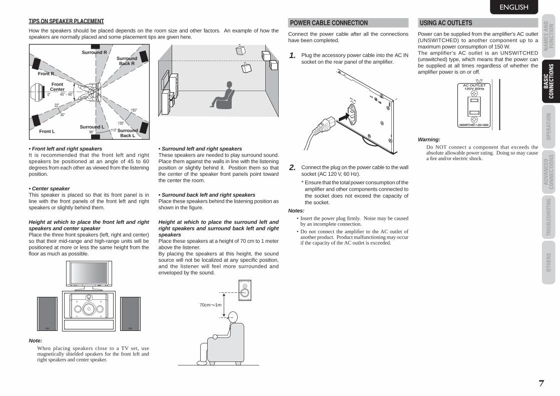
TIPS ON SPEAKER PLACEMENT
How the speakers should be placed depends on the room size and other factors. An example of how the speakers are normally placed and some placement tips are given here.
Front R
Front L
Front Center
Surround LSurround
Back L
Surround RSurround Back R
• Front left and right speakersIt is recommended that the front left and right speakers be positioned at an angle of 45 to 60 degrees from each other as viewed from the listening position.
• Center speakerThis speaker is placed so that its front panel is in line with the front panels of the front left and right speakers or slightly behind them.
Height at which to place the front left and right speakers and center speakerPlace the three front speakers (left, right and center) so that their mid-range and high-range units will be positioned at more or less the same height from the fl oor as much as possible.
Note:When placing speakers close to a TV set, use magnetically shielded speakers for the front left and right speakers and center speaker.
• Surround left and right speakersThese speakers are needed to play surround sound. Place them against the walls in line with the listening position or slightly behind it. Position them so that the center of the speaker front panels point toward the center the room.
• Surround back left and right speakersPlace these speakers behind the listening position as shown in the fi gure.
Height at which to place the surround left and right speakers and surround back left and right speakersPlace these speakers at a height of 70 cm to 1 meter above the listener.By placing the speakers at this height, the sound source will not be localized at any specifi c position, and the listener will feel more surrounded and enveloped by the sound.
70cm 1m
POWER CABLE CONNECTION
Connect the power cable after all the connections have been completed.
1. Plug the accessory power cable into the AC IN socket on the rear panel of the amplifi er.
2. Connect the plug on the power cable to the wall socket (AC 120 V, 60 Hz).
* Ensure that the total power consumption of the amplifi er and other components connected to the socket does not exceed the capacity of the socket.
Notes:• Insert the power plug fi rmly. Noise may be caused
by an incomplete connection.
• Do not connect the amplifi er to the AC outlet of another product. Product malfunctioning may occur if the capacity of the AC outlet is exceeded.
USING AC OUTLETS
Power can be supplied from the amplifi er's AC outlet (UNSWITCHED) to another component up to a maximum power consumption of 150 W.The amplifier's AC outlet is an UNSWITCHED (unswitched) type, which means that the power can be supplied at all times regardless of whether the amplifi er power is on or off.
120V 60Hz120V 60Hz
UNSWITCHED 1.25A 150WUNSWITCHED 1.25A 150W
AC OUTLETAC OUTLET
Warning:Do NOT connect a component that exceeds the absolute allowable power rating. Doing so may cause a fi re and/or electric shock.
MM8003_U_01_ENG.indd 7MM8003_U_01_ENG.indd 7 08.4.28 2:19:58 PM08.4.28 2:19:58 PM
BA
SIC CO
NN
ECTION
SO
PERATION
AD
VAN
CED
CON
NECTIO
NS
TROUBLESHOOTINGO
THERS
NA
MES A
ND
FU
NCTIO
NO
PERATION
ENGLISH
8
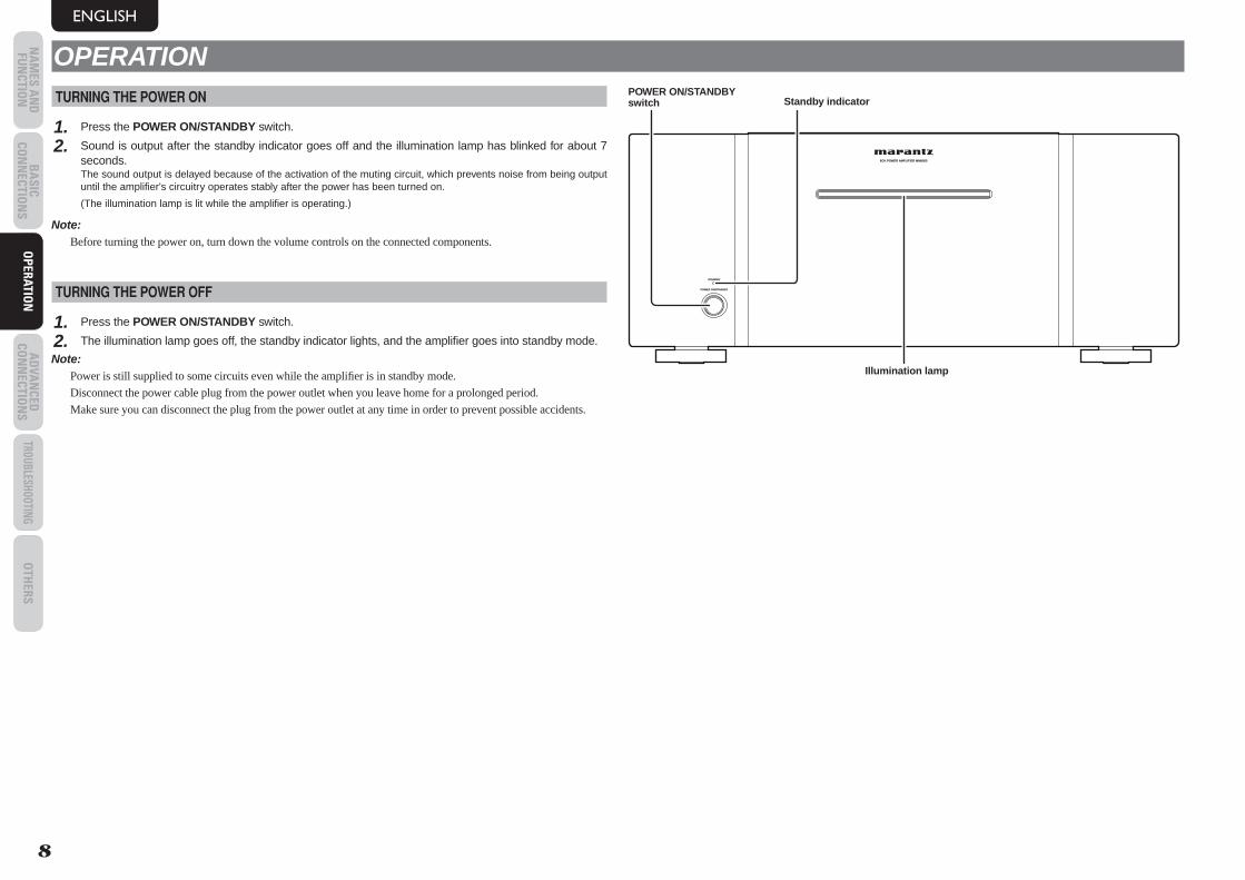
OPERATIONTURNING THE POWER ON
1. Press the POWER ON/STANDBY switch.
2. Sound is output after the standby indicator goes off and the illumination lamp has blinked for about 7 seconds.
The sound output is delayed because of the activation of the muting circuit, which prevents noise from being output until the amplifi er's circuitry operates stably after the power has been turned on.
(The illumination lamp is lit while the amplifi er is operating.)
Note:Before turning the power on, turn down the volume controls on the connected components.
TURNING THE POWER OFF
1. Press the POWER ON/STANDBY switch.
2. The illumination lamp goes off, the standby indicator lights, and the amplifi er goes into standby mode.
Note:Power is still supplied to some circuits even while the amplifi er is in standby mode.
Disconnect the power cable plug from the power outlet when you leave home for a prolonged period.
Make sure you can disconnect the plug from the power outlet at any time in order to prevent possible accidents.
8CH POWER AMPLIFIER MM80038CH POWER AMPLIFIER MM8003
POWER ON/STANDBYPOWER ON/STANDBY
STANDBYSTANDBY
POWER ON/STANDBY switch
Illumination lamp
Standby indicator
MM8003_U_01_ENG.indd 8MM8003_U_01_ENG.indd 8 08.4.28 2:19:58 PM08.4.28 2:19:58 PM
BA
SIC
CON
NEC
TIO
NS
OPE
RATI
ON
AD
VAN
CED
CO
NN
ECTI
ON
STR
OUBL
ESHO
OTIN
GO
THER
SN
AM
ES A
ND
FU
NCT
ION
AD
VAN
CED
CO
NN
ECTI
ON
S
ENGLISH
9
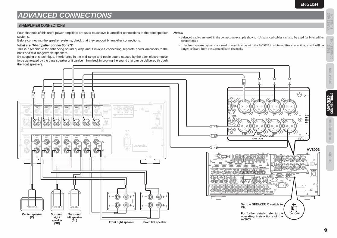
ADVANCED CONNECTIONSBI-AMPLIFIER CONNECTIONS
Four channels of this unit's power amplifi ers are used to achieve bi-amplifi er connections to the front speaker systems.Before connecting the speaker systems, check that they support bi-amplifi er connections.
What are "bi-amplifi er connections"?This is a technique for enhancing sound quality, and it involves connecting separate power amplifi ers to the bass and mid-range/treble speakers.By adopting this technique, interference in the mid-range and treble sound caused by the back electromotive force generated by the bass speaker unit can be minimized, improving the sound that can be delivered through the front speakers.
Notes:• Balanced cables are used in the connection example shown. (Unbalanced cables can also be used for bi-amplifi er
connections.)
• If the front speaker systems are used in combination with the AV8003 in a bi-amplifi er connection, sound will no longer be heard from the surround back channels.
DC CONTROLDC CONTROLININ
FLASHERFLASHER REMOTE CONTROLREMOTE CONTROL
SPEAKER SYSTEMSSPEAKER SYSTEMS6-8 OHMS6-8 OHMS
AC INAC IN
123
CONNECTION
GND HOT(+)COLD(-)3
21
BALANCEDBALANCEDUNBALANCEDUNBALANCED
BALANCEDBALANCED
UNBALANCEDUNBALANCED
BALANCEDBALANCEDUNBALANCEDUNBALANCED
BALANCEDBALANCEDUNBALANCEDUNBALANCED
BALANCEDBALANCEDUNBALANCEDUNBALANCED
BALANCEDBALANCEDUNBALANCEDUNBALANCED
BALANCEDBALANCEDUNBALANCEDUNBALANCED
BALANCEDBALANCEDUNBALANCEDUNBALANCED
BALANCEDBALANCEDUNBALANCEDUNBALANCED
MODEL NO. MM8003MODEL NO. MM8003
OUTOUT OUTOUT ININ
CHANNEL 1CHANNEL 1CHANNEL 2CHANNEL 2CHANNEL 3CHANNEL 3CHANNEL 4CHANNEL 4CHANNEL 5CHANNEL 5CHANNEL 6CHANNEL 6CHANNEL 7CHANNEL 7CHANNEL 8CHANNEL 8
CHANNEL 1CHANNEL 1CHANNEL 2CHANNEL 2CHANNEL 3CHANNEL 3CHANNEL 4CHANNEL 4CHANNEL 5CHANNEL 5CHANNEL 6CHANNEL 6CHANNEL 7CHANNEL 7CHANNEL 8CHANNEL 8
ININ
((LL))((RR))((SLSL))((SRSR))((SBLSBL))((SBRSBR))((CC))((OPTIONOPTION))
((LL))((RR))((SLSL))((SRSR))((SBLSBL))((SBRSBR))((CC))((OPTIONOPTION))
PUSH PUSH PUSH PUSH PUSH PUSH PUSH PUSH
120V 60Hz120V 60Hz
UNSWITCHED 1.25A 150WUNSWITCHED 1.25A 150W
AC OUTLETAC OUTLET
PUSH PUSH PUSH PUSH PUSH PUSH PUSH
CHANNEL 1CHANNEL 1CHANNEL 2CHANNEL 2CHANNEL 3CHANNEL 3CHANNEL 4CHANNEL 4CHANNEL 5CHANNEL 5CHANNEL 6CHANNEL 6CHANNEL 7CHANNEL 7((LL))((RR))((SLSL))((SRSR))((SBLSBL))((SBRSBR))((CC))
SPEAKER SYSTEMSSPEAKER SYSTEMS6-8 OHMS6-8 OHMS
CHANNEL 1CHANNEL 1CHANNEL 2CHANNEL 2CHANNEL 3CHANNEL 3CHANNEL 4CHANNEL 4CHANNEL 5CHANNEL 5CHANNEL 6CHANNEL 6CHANNEL 7CHANNEL 7((LL))((RR))((SLSL))((SRSR))((SBLSBL))((SBRSBR))((CC))
LL SRSR SLSLRR
RR
SRSR SLSL
SWSW CC
SBRSBR SBLSBL
LL
SBLSBL SWSW CCSBRSBR
FM FM ((7575ΩΩ)) GNDGND AMAM
ANTENNAANTENNA
OUTOUTPUTPUT
11
OUTOUTPUTPUT
22
INPUT 3INPUT 3((VCR1VCR1)) OUTPUT 1OUTPUT 1 OUTPUT 2OUTPUT 2INPUT 1INPUT 1((TVTV)) INPUT 4INPUT 4((DSS/VCR2DSS/VCR2))INPUT 2INPUT 2((DVDDVD))
COMPONENTCOMPONENTVIDEOVIDEO
CCBB//PPBBCCRR//PPRR
CCRR//PPRRCCRR//PPRR
CCBB//PPBBCCBB//PPBBYY YYYY
INPUT 1INPUT 1((TVTV))
INPUT 4INPUT 4((DSSDSS // VCR2VCR2))INPUT 3INPUT 3((VCR1VCR1))
INPUT 2INPUT 2((DVDDVD))
RS-232CRS-232C SPEAKER CSPEAKER CSIRIUSSIRIUS
NETWORKNETWORK
ONON OFFOFF
13
CONNECTIONGNDHOT(+)COLD(-)3
21
2
AC INAC IN
OUTOUTININ ININOUTOUTVIDEOVIDEO
MONITORMONITOROUTOUT
DVDDVD((22)) DSS/VCR2DSS/VCR2((44))TVTV((11)) ZONEZONEOUTOUT
VCR1VCR1((33)) DVDDVD((22))TVTV((11))
22
11
FLASHERFLASHERININ
IRIRRECEIVERRECEIVER
ININ
66 COAX.COAX.5544
OUTOUT
ININ 11
22
EMITTEREMITTER OUT OUT SELECTORSELECTOR
DC OUTDC OUT
RR LL
OUTOUT
RR
OUTOUT
LLTAPETAPE
OUTOUTININ RROUTOUT
LL
DSS/VCR2DSS/VCR2
AUDIOAUDIO
BALANCEDBALANCED
PRE OUTPRE OUT
UNBALANCEDUNBALANCED
TVTV
ININ SRSR
VCR1VCR1
ININ
DVDDVD SLSL
SBRSBR
SBLSBL
SWSW
CC
AA BB
7.1CH7.1CHININ
((AUXAUX))
332211 OPT.OPT.
MODEL NO. AV8003MODEL NO. AV8003
DIGITAL INDIGITAL IN DIGITAL OUTDIGITAL OUT MAINMAIN ZONEZONE
CD/CDRCD/CDR
ININ
REMOTEREMOTE 123
BALANCEDBALANCEDUNBALANCEDUNBALANCED
ININ OUTOUT
S-VIDEOS-VIDEO
ININ OUTOUTDSS/VCR2DSS/VCR2((44))VCR1VCR1((33)) MONI. OUTMONI. OUT
CD/CDR BALANCED INCD/CDR BALANCED IN
ZONE OUTZONE OUT
CONNECTIONGNDHOT(+)COLD(-)3
21
PUSH PUSH
ONON OFFOFF
LL SRSR SLSLRR
SLSL
CC
SBLSBL
LL
SBLSBL SWSW CCSBRSBR
RS-232CRS-232C
NNETWORK
CONNGNHOCO3
21
BALANCEDBALANCEDANCEDUNBALANCED
SPEAKER CSPEAKER C
ONON OFFOFF
PRE OUTPRE OUT
AV8003
Set the SPEAKER C switch to ON.
For further details, refer to the operating instructions of the AV8003.
Surround right
speaker (SR)
Surround left speaker
(SL)
Center speaker (C)
Front left speakerFront right speaker
MM8003_U_01_ENG.indd 9MM8003_U_01_ENG.indd 9 08.4.28 2:19:58 PM08.4.28 2:19:58 PM
BA
SIC CO
NN
ECTION
SO
PERATION
AD
VAN
CED
CON
NECTIO
NS
TROUBLESHOOTINGO
THERS
NA
MES A
ND
FU
NCTIO
NA
DVA
NCED
CO
NN
ECTION
S
ENGLISH
10
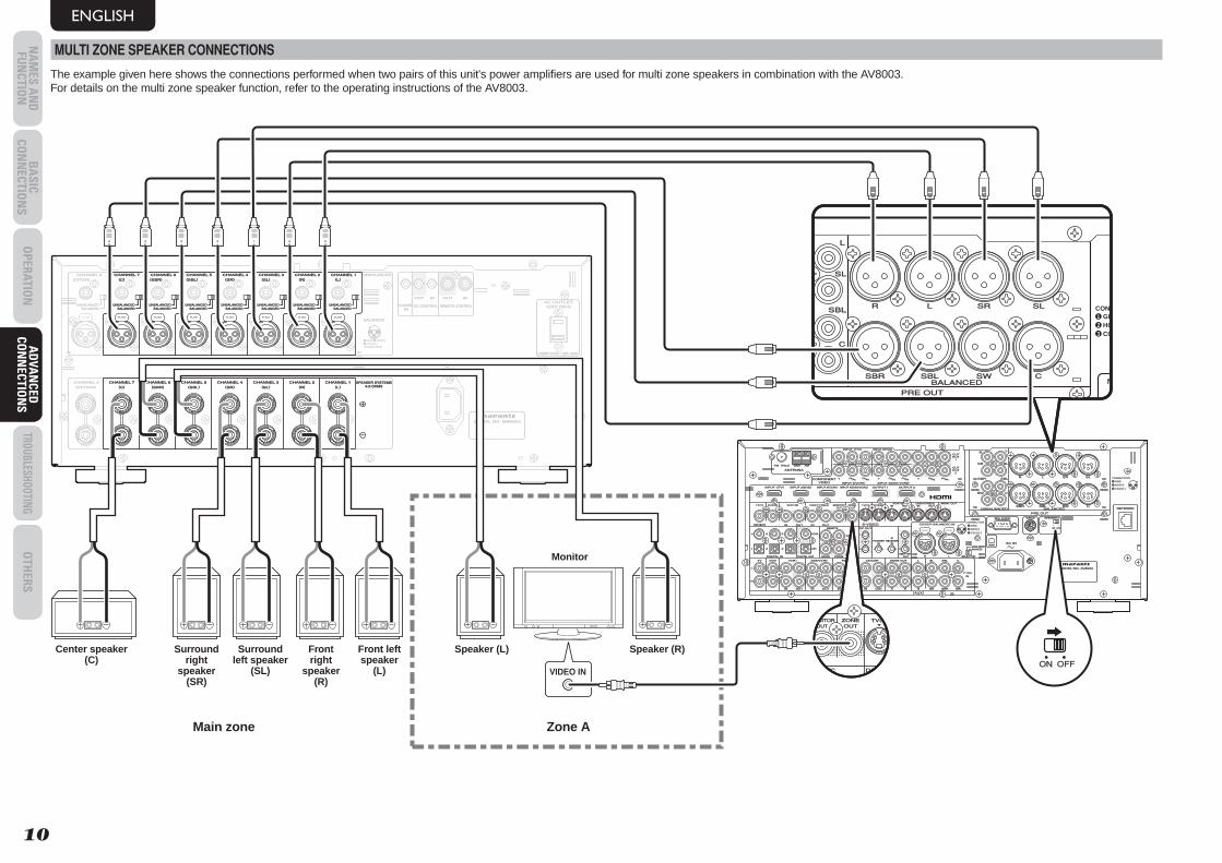
MULTI ZONE SPEAKER CONNECTIONS
The example given here shows the connections performed when two pairs of this unit's power amplifi ers are used for multi zone speakers in combination with the AV8003.For details on the multi zone speaker function, refer to the operating instructions of the AV8003.
DC CONTROLDC CONTROLININ
FLASHERFLASHER REMOTE CONTROLREMOTE CONTROL
SPEAKER SYSTEMSSPEAKER SYSTEMS6-8 OHMS6-8 OHMS
AC INAC IN
123
CONNECTION
GND HOT(+)COLD(-)3
21
BALANCEDBALANCEDUNBALANCEDUNBALANCED
BALANCEDBALANCED
UNBALANCEDUNBALANCED
BALANCEDBALANCEDUNBALANCEDUNBALANCED
BALANCEDBALANCEDUNBALANCEDUNBALANCED
BALANCEDBALANCEDUNBALANCEDUNBALANCED
BALANCEDBALANCEDUNBALANCEDUNBALANCED
BALANCEDBALANCEDUNBALANCEDUNBALANCED
BALANCEDBALANCEDUNBALANCEDUNBALANCED
BALANCEDBALANCEDUNBALANCEDUNBALANCED
MODEL NO. MM8003MODEL NO. MM8003
OUTOUT OUTOUT ININ
CHANNEL 1CHANNEL 1CHANNEL 2CHANNEL 2CHANNEL 3CHANNEL 3CHANNEL 4CHANNEL 4CHANNEL 5CHANNEL 5CHANNEL 6CHANNEL 6CHANNEL 7CHANNEL 7CHANNEL 8CHANNEL 8
CHANNEL 1CHANNEL 1CHANNEL 2CHANNEL 2CHANNEL 3CHANNEL 3CHANNEL 4CHANNEL 4CHANNEL 5CHANNEL 5CHANNEL 6CHANNEL 6CHANNEL 7CHANNEL 7CHANNEL 8CHANNEL 8
ININ
((LL))((RR))((SLSL))((SRSR))((SBLSBL))((SBRSBR))((CC))((OPTIONOPTION))
((LL))((RR))((SLSL))((SRSR))((SBLSBL))((SBRSBR))((CC))((OPTIONOPTION))
PUSH PUSH PUSH PUSH PUSH PUSH PUSH PUSH
120V 60Hz120V 60Hz
UNSWITCHED 1.25A 150WUNSWITCHED 1.25A 150W
AC OUTLETAC OUTLET
BALANCEDBALANCEDUNBALANCEDUNBALANCED
BALANCEDBALANCEDUNBALANCEDUNBALANCED
BALANCEDBALANCEDUNBALANCEDUNBALANCED
BALANCEDBALANCEDUNBALANCEDUNBALANCED
BALANCEDBALANCEDUNBALANCEDUNBALANCED
BALANCEDBALANCEDUNBALANCEDUNBALANCED
PUSH PUSH PUSH PUSH PUSH PUSH
CHANNEL 1CHANNEL 1CHANNEL 2CHANNEL 2CHANNEL 3CHANNEL 3CHANNEL 4CHANNEL 4CHANNEL 5CHANNEL 5CHANNEL 6CHANNEL 6CHANNEL 7CHANNEL 7((LL))((RR))((SLSL))((SRSR))((SBLSBL))((SBRSBR))((CC))
CHANNEL 1CHANNEL 1((LL))
PUSH
BALANCEDBALANCEDUNBALANCEDUNBALANCED
CHANNEL 2CHANNEL 2CHANNEL 3CHANNEL 3CHANNEL 4CHANNEL 4CHANNEL 5CHANNEL 5CHANNEL 6CHANNEL 6CHANNEL 7CHANNEL 7((RR))((SLSL))((SRSR))((SBLSBL))((SBRSBR))((CC))
SPEAKER SYSTEMSSPEAKER SYSTEMS6-8 OHMS6-8 OHMS
LL SRSR SLSLRR
RR
SRSR SLSL
SWSW CC
SBRSBR SBLSBL
LL
SBLSBL SWSW CCSBRSBR
FM FM ((7575ΩΩ)) GNDGND AMAM
ANTENNAANTENNA
OUTOUTPUTPUT
11
OUTOUTPUTPUT
22
INPUT 3INPUT 3((VCR1VCR1)) OUTPUT 1OUTPUT 1 OUTPUT 2OUTPUT 2INPUT 1INPUT 1((TVTV)) INPUT 4INPUT 4((DSS/VCR2DSS/VCR2))INPUT 2INPUT 2((DVDDVD))
COMPONENTCOMPONENTVIDEOVIDEO
CCBB//PPBBCCRR//PPRR
CCRR//PPRRCCRR//PPRR
CCBB//PPBBCCBB//PPBBYY YYYY
INPUT 1INPUT 1((TVTV))
INPUT 4INPUT 4((DSSDSS // VCR2VCR2))INPUT 3INPUT 3((VCR1VCR1))
INPUT 2INPUT 2((DVDDVD))
RS-232CRS-232C SPEAKER CSPEAKER CSIRIUSSIRIUS
NETWORKNETWORK
ONON OFFOFF
13
CONNECTIONGNDHOT(+)COLD(-)3
21
2
AC INAC IN
OUTOUTININ ININOUTOUTVIDEOVIDEO
MONITORMONITOROUTOUT
DVDDVD((22)) DSS/VCR2DSS/VCR2((44))TVTV((11)) ZONEZONEOUTOUT
VCR1VCR1((33)) DVDDVD((22))TVTV((11))
22
11
FLASHERFLASHERININ
IRIRRECEIVERRECEIVER
ININ
66 COAX.COAX.5544
OUTOUT
ININ 11
22
EMITTEREMITTER OUT OUT SELECTORSELECTOR
DC OUTDC OUT
RR LL
OUTOUT
RR
OUTOUT
LLTAPETAPE
OUTOUTININ RROUTOUT
LL
DSS/VCR2DSS/VCR2
AUDIOAUDIO
BALANCEDBALANCED
PRE OUTPRE OUT
UNBALANCEDUNBALANCED
TVTV
ININ SRSR
VCR1VCR1
ININ
DVDDVD SLSL
SBRSBR
SBLSBL
SWSW
CC
AA BB
7.1CH7.1CHININ
((AUXAUX))
332211 OPT.OPT.
MODEL NO. AV8003MODEL NO. AV8003
DIGITAL INDIGITAL IN DIGITAL OUTDIGITAL OUT MAINMAIN ZONEZONE
CD/CDRCD/CDR
ININ
REMOTEREMOTE 123
BALANCEDBALANCEDUNBALANCEDUNBALANCED
ININ OUTOUT
S-VIDEOS-VIDEO
ININ OUTOUTDSS/VCR2DSS/VCR2((44))VCR1VCR1((33)) MONI. OUTMONI. OUT
CD/CDR BALANCED INCD/CDR BALANCED IN
ZONE OUTZONE OUT
CONNECTIONGNDHOT(+)COLD(-)3
21
PUSH PUSH
ONON OFFOFF
LL SRSR SLSLRR
SLSL
CC
SBLSBL
LL
SBLSBL SWSW CCSBRSBR
RS-232CRS-232C
NNETWORK
CONNGNHOCO3
21
AC IN
BALANCEDBALANCEDANCEDUNBALANCED
SPEAKER CSPEAKER C
ONON OFFOFF
PRE OUTPRE OUT
MODEL NO. AV8003OUTPUT
1
OUTPUT
2
INPUT 3(VCR1) OUTPUT 1 OUTPUT 2INPUT 4(DSS/VCR2)
HDMI
COMPONENTVIDEO
CB/PBCR/PR
CR/PRCR/PR
CB/PBCB/PBY YY
INPUT 1(TV)
INPUT 4(DSS / VCR2)INPUT 3(VCR1)
INPUT 2(DVD)
IN OUT S-VIDEOIN OUT
ONITORMONITOROUTOUT
ZONEZONEOUTOUT
DVD(2) DSS/VCR2(4)VCR1(3)TVTV((11)) MONI. OUT
DC OUDC OUTULTI RCMULTI RC CD/CDR INVIDEO IN
Surround right
speaker (SR)
Surround left speaker
(SL)
Front right
speaker (R)
Front left speaker
(L)
Center speaker (C)
Main zone
Speaker (L) Speaker (R)
Zone A
Monitor
MM8003_U_01_ENG.indd 10MM8003_U_01_ENG.indd 10 08.4.28 2:19:59 PM08.4.28 2:19:59 PM
BA
SIC
CON
NEC
TIO
NS
OPE
RATI
ON
AD
VAN
CED
CO
NN
ECTI
ON
STR
OUBL
ESHO
OTIN
GO
THER
SN
AM
ES A
ND
FU
NCT
ION
AD
VAN
CED
CO
NN
ECTI
ON
S
ENGLISH
11
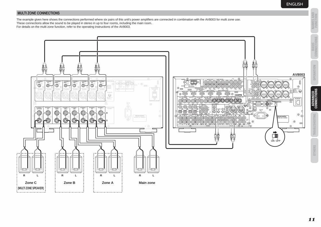
MULTI ZONE CONNECTIONS
The example given here shows the connections performed where six pairs of this unit's power amplifi ers are connected in combination with the AV8003 for multi zone use.These connections allow the sound to be played in stereo in up to four rooms, including the main room.For details on the multi zone function, refer to the operating instructions of the AV8003.
DC CONTROLDC CONTROLININ
FLASHERFLASHER REMOTE CONTROLREMOTE CONTROL
SPEAKER SYSTEMSSPEAKER SYSTEMS6-8 OHMS6-8 OHMS
AC INAC IN
123
CONNECTION
GND HOT(+)COLD(-)3
21
BALANCEDBALANCEDUNBALANCEDUNBALANCED
BALANCEDBALANCED
UNBALANCEDUNBALANCED
BALANCEDBALANCEDUNBALANCEDUNBALANCED
BALANCEDBALANCEDUNBALANCEDUNBALANCED
BALANCEDBALANCEDUNBALANCEDUNBALANCED
BALANCEDBALANCEDUNBALANCEDUNBALANCED
BALANCEDBALANCEDUNBALANCEDUNBALANCED
BALANCEDBALANCEDUNBALANCEDUNBALANCED
BALANCEDBALANCEDUNBALANCEDUNBALANCED
MODEL NO. MM8003MODEL NO. MM8003
OUTOUT OUTOUT ININ
CHANNEL 1CHANNEL 1CHANNEL 2CHANNEL 2CHANNEL 3CHANNEL 3CHANNEL 4CHANNEL 4CHANNEL 5CHANNEL 5CHANNEL 6CHANNEL 6CHANNEL 7CHANNEL 7CHANNEL 8CHANNEL 8
CHANNEL 1CHANNEL 1CHANNEL 2CHANNEL 2CHANNEL 3CHANNEL 3CHANNEL 4CHANNEL 4CHANNEL 5CHANNEL 5CHANNEL 6CHANNEL 6CHANNEL 7CHANNEL 7CHANNEL 8CHANNEL 8
ININ
((LL))((RR))((SLSL))((SRSR))((SBLSBL))((SBRSBR))((CC))((OPTIONOPTION))
((LL))((RR))((SLSL))((SRSR))((SBLSBL))((SBRSBR))((CC))((OPTIONOPTION))
PUSH PUSH PUSH PUSH PUSH PUSH PUSH PUSH
120V 60Hz120V 60Hz
UNSWITCHED 1.25A 150WUNSWITCHED 1.25A 150W
AC OUTLETAC OUTLET
CHANNEL 1CHANNEL 1CHANNEL 2CHANNEL 2CHANNEL 3CHANNEL 3CHANNEL 4CHANNEL 4CHANNEL 5CHANNEL 5CHANNEL 6CHANNEL 6CHANNEL 7CHANNEL 7CHANNEL 8CHANNEL 8((LL))((RR))((SLSL))((SRSR))((SBLSBL))((SBRSBR))((CC))((OPTIONOPTION))
CHANNEL 1CHANNEL 1CHANNEL 2CHANNEL 2CHANNEL 3CHANNEL 3CHANNEL 4CHANNEL 4CHANNEL 5CHANNEL 5CHANNEL 6CHANNEL 6CHANNEL 7CHANNEL 7CHANNEL 8CHANNEL 8((LL))((RR))((SLSL))((SRSR))((SBLSBL))((SBRSBR))((CC))((OPTIONOPTION))
AV8003
LL SRSR SLSLRR
RR
SRSR SLSL
SWSW CC
SBRSBR SBLSBL
LL
SBLSBL SWSW CCSBRSBR
FM FM ((7575ΩΩ)) GNDGND AMAM
ANTENNAANTENNA
OUTOUTPUTPUT
11
OUTOUTPUTPUT
22
INPUT 3INPUT 3((VCR1VCR1)) OUTPUT 1OUTPUT 1 OUTPUT 2OUTPUT 2INPUT 1INPUT 1((TVTV)) INPUT 4INPUT 4((DSS/VCR2DSS/VCR2))INPUT 2INPUT 2((DVDDVD))
COMPONENTCOMPONENTVIDEOVIDEO
CCBB//PPBBCCRR//PPRR
CCRR//PPRRCCRR//PPRR
CCBB//PPBBCCBB//PPBBYY YYYY
INPUT 1INPUT 1((TVTV))
INPUT 4INPUT 4((DSSDSS // VCR2VCR2))INPUT 3INPUT 3((VCR1VCR1))
INPUT 2INPUT 2((DVDDVD))
RS-232CRS-232C SPEAKER CSPEAKER CSIRIUSSIRIUS
NETWORKNETWORK
ONON OFFOFF
13
CONNECTIONGNDHOT(+)COLD(-)3
21
2
AC INAC IN
OUTOUTININ ININOUTOUTVIDEOVIDEO
MONITORMONITOROUTOUT
DVDDVD((22)) DSS/VCR2DSS/VCR2((44))TVTV((11)) ZONEZONEOUTOUT
VCR1VCR1((33)) DVDDVD((22))TVTV((11))
22
11
FLASHERFLASHERININ
IRIRRECEIVERRECEIVER
ININ
66 COAX.COAX.5544
OUTOUT
ININ 11
22
EMITTEREMITTER OUT OUT SELECTORSELECTOR
DC OUTDC OUT
RR LL
OUTOUT
RR
OUTOUT
LLTAPETAPE
OUTOUTININ RROUTOUT
LL
DSS/VCR2DSS/VCR2
AUDIOAUDIO
BALANCEDBALANCED
PRE OUTPRE OUT
UNBALANCEDUNBALANCED
TVTV
ININ SRSR
VCR1VCR1
ININ
DVDDVD SLSL
SBRSBR
SBLSBL
SWSW
CC
AA BB
7.1CH7.1CHININ
((AUXAUX))
332211 OPT.OPT.
MODEL NO. AV8003MODEL NO. AV8003
DIGITAL INDIGITAL IN DIGITAL OUTDIGITAL OUT MAINMAIN ZONEZONE
CD/CDRCD/CDR
ININ
REMOTEREMOTE 123
BALANCEDBALANCEDUNBALANCEDUNBALANCED
ININ OUTOUT
S-VIDEOS-VIDEO
ININ OUTOUTDSS/VCR2DSS/VCR2((44))VCR1VCR1((33)) MONI. OUTMONI. OUT
CD/CDR BALANCED INCD/CDR BALANCED IN
ZONE OUTZONE OUT
CONNECTIONGNDHOT(+)COLD(-)3
21
PUSH PUSH
ONON OFFOFF
L R R L
R LR LR LLR
L R LR
Main zoneZone AZone BZone C
(MULTI ZONE SPEAKER)
R LR LR LR L
MM8003_U_01_ENG.indd 11MM8003_U_01_ENG.indd 11 08.4.28 2:19:59 PM08.4.28 2:19:59 PM
BA
SIC CO
NN
ECTION
SO
PERATION
AD
VAN
CED
CON
NECTIO
NS
TROUBLESHOOTINGO
THERS
NA
MES A
ND
FU
NCTIO
NA
DVA
NCED
CO
NN
ECTION
S
ENGLISH
12
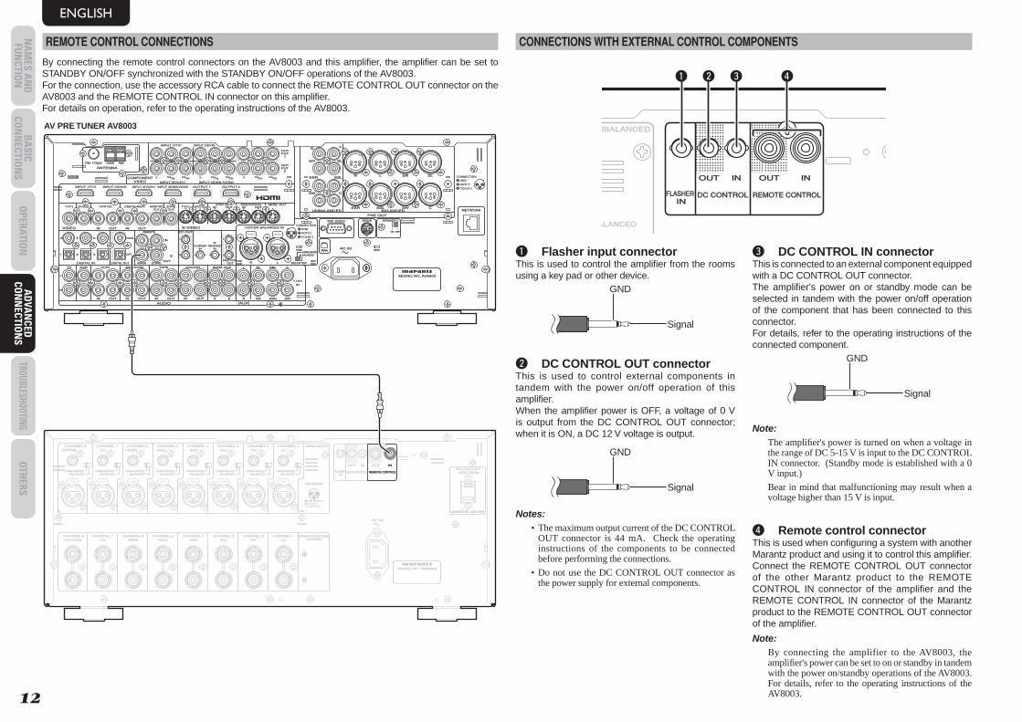
REMOTE CONTROL CONNECTIONS
By connecting the remote control connectors on the AV8003 and this amplifi er, the amplifi er can be set to STANDBY ON/OFF synchronized with the STANDBY ON/OFF operations of the AV8003.For the connection, use the accessory RCA cable to connect the REMOTE CONTROL OUT connector on the AV8003 and the REMOTE CONTROL IN connector on this amplifi er.For details on operation, refer to the operating instructions of the AV8003.
DC CONTROLDC CONTROLININ
FLASHERFLASHER REMOTE CONTROLREMOTE CONTROL
SPEAKER SYSTEMSSPEAKER SYSTEMS6-8 OHMS6-8 OHMS
AC INAC IN
123
CONNECTION
GND HOT(+)COLD(-)3
21
BALANCEDBALANCEDUNBALANCEDUNBALANCED
BALANCEDBALANCED
UNBALANCEDUNBALANCED
BALANCEDBALANCEDUNBALANCEDUNBALANCED
BALANCEDBALANCEDUNBALANCEDUNBALANCED
BALANCEDBALANCEDUNBALANCEDUNBALANCED
BALANCEDBALANCEDUNBALANCEDUNBALANCED
BALANCEDBALANCEDUNBALANCEDUNBALANCED
BALANCEDBALANCEDUNBALANCEDUNBALANCED
BALANCEDBALANCEDUNBALANCEDUNBALANCED
MODEL NO. MM8003MODEL NO. MM8003
OUTOUT OUTOUT ININ
CHANNEL 1CHANNEL 1CHANNEL 2CHANNEL 2CHANNEL 3CHANNEL 3CHANNEL 4CHANNEL 4CHANNEL 5CHANNEL 5CHANNEL 6CHANNEL 6CHANNEL 7CHANNEL 7CHANNEL 8CHANNEL 8
CHANNEL 1CHANNEL 1CHANNEL 2CHANNEL 2CHANNEL 3CHANNEL 3CHANNEL 4CHANNEL 4CHANNEL 5CHANNEL 5CHANNEL 6CHANNEL 6CHANNEL 7CHANNEL 7CHANNEL 8CHANNEL 8
ININ
((LL))((RR))((SLSL))((SRSR))((SBLSBL))((SBRSBR))((CC))((OPTIONOPTION))
((LL))((RR))((SLSL))((SRSR))((SBLSBL))((SBRSBR))((CC))((OPTIONOPTION))
PUSH PUSH PUSH PUSH PUSH PUSH PUSH PUSH
120V 60Hz120V 60Hz
UNSWITCHED 1.25A 150WUNSWITCHED 1.25A 150W
AC OUTLETAC OUTLETREMOTE CONTROLREMOTE CONTROL
ININ
LL SRSR SLSLRR
RR
SRSR SLSL
SWSW CC
SBRSBR SBLSBL
LL
SBLSBL SWSW CCSBRSBR
FM FM ((7575ΩΩ)) GNDGND AMAM
ANTENNAANTENNA
OUTOUTPUTPUT
11
OUTOUTPUTPUT
22
INPUT 3INPUT 3((VCR1VCR1)) OUTPUT 1OUTPUT 1 OUTPUT 2OUTPUT 2INPUT 1INPUT 1((TVTV)) INPUT 4INPUT 4((DSS/VCR2DSS/VCR2))INPUT 2INPUT 2((DVDDVD))
COMPONENTCOMPONENTVIDEOVIDEO
CCBB//PPBBCCRR//PPRR
CCRR//PPRRCCRR//PPRR
CCBB//PPBBCCBB//PPBBYY YYYY
INPUT 1INPUT 1((TVTV))
INPUT 4INPUT 4((DSSDSS // VCR2VCR2))INPUT 3INPUT 3((VCR1VCR1))
INPUT 2INPUT 2((DVDDVD))
RS-232CRS-232C SPEAKER CSPEAKER CSIRIUSSIRIUS
NETWORKNETWORK
ONON OFFOFF
13
CONNECTIONGNDHOT(+)COLD(-)3
21
2
AC INAC IN
OUTOUTININ ININOUTOUTVIDEOVIDEO
MONITORMONITOROUTOUT
DVDDVD((22)) DSS/VCR2DSS/VCR2((44))TVTV((11)) ZONEZONEOUTOUT
VCR1VCR1((33)) DVDDVD((22))TVTV((11))
22
11
FLASHERFLASHERININ
IRIRRECEIVERRECEIVER
ININ
66 COAX.COAX.5544
OUTOUT
ININ 11
22
EMITTEREMITTER OUT OUT SELECTORSELECTOR
DC OUTDC OUT
RR LL
OUTOUT
RR
OUTOUT
LLTAPETAPE
OUTOUTININ RROUTOUT
LL
DSS/VCR2DSS/VCR2
AUDIOAUDIO
BALANCEDBALANCED
PRE OUTPRE OUT
UNBALANCEDUNBALANCED
TVTV
ININ SRSR
VCR1VCR1
ININ
DVDDVD SLSL
SBRSBR
SBLSBL
SWSW
CC
AA BB
7.1CH7.1CHININ
((AUXAUX))
332211 OPT.OPT.
MODEL NO. AV8003MODEL NO. AV8003
DIGITAL INDIGITAL IN DIGITAL OUTDIGITAL OUT MAINMAIN ZONEZONE
CD/CDRCD/CDR
ININ
REMOTEREMOTE 123
BALANCEDBALANCEDUNBALANCEDUNBALANCED
ININ OUTOUT
S-VIDEOS-VIDEO
ININ OUTOUTDSS/VCR2DSS/VCR2((44))VCR1VCR1((33)) MONI. OUTMONI. OUT
CD/CDR BALANCED INCD/CDR BALANCED IN
ZONE OUTZONE OUT
CONNECTIONGNDHOT(+)COLD(-)3
21
PUSH PUSH
AV PRE TUNER AV8003
CONNECTIONS WITH EXTERNAL CONTROL COMPONENTS
DC CONTROLDC CONTROLININ
FLASHERFLASHER REMOTE CONTROLREMOTE CONTROL
ALANCEDBALANCED
NBALANCEDUNBALANCED
OUTOUT OUTOUT ININININ
q w e r
q Flasher input connectorThis is used to control the amplifi er from the rooms using a key pad or other device.
GND
Signal
w DC CONTROL OUT connectorThis is used to control external components in tandem with the power on/off operation of this amplifi er.When the amplifi er power is OFF, a voltage of 0 V is output from the DC CONTROL OUT connector; when it is ON, a DC 12 V voltage is output.
GND
Signal
Notes:• The maximum output current of the DC CONTROL
OUT connector is 44 mA. Check the operating instructions of the components to be connected before performing the connections.
• Do not use the DC CONTROL OUT connector as the power supply for external components.
e DC CONTROL IN connectorThis is connected to an external component equipped with a DC CONTROL OUT connector.The amplifi er's power on or standby mode can be selected in tandem with the power on/off operation of the component that has been connected to this connector.For details, refer to the operating instructions of the connected component.
GND
Signal
Note:The amplifi er's power is turned on when a voltage in the range of DC 5-15 V is input to the DC CONTROL IN connector. (Standby mode is established with a 0 V input.)
Bear in mind that malfunctioning may result when a voltage higher than 15 V is input.
r Remote control connectorThis is used when confi guring a system with another Marantz product and using it to control this amplifi er.Connect the REMOTE CONTROL OUT connector of the other Marantz product to the REMOTE CONTROL IN connector of the amplifi er and the REMOTE CONTROL IN connector of the Marantz product to the REMOTE CONTROL OUT connector of the amplifi er.
Note:By connecting the amplifier to the AV8003, the amplifi er's power can be set to on or standby in tandem with the power on/standby operations of the AV8003. For details, refer to the operating instructions of the AV8003.
MM8003_U_01_ENG.indd 12MM8003_U_01_ENG.indd 12 08.4.28 2:19:59 PM08.4.28 2:19:59 PM
BA
SIC
CON
NEC
TIO
NS
OPE
RATI
ON
AD
VAN
CED
CO
NN
ECTI
ON
STR
OUBL
ESHO
OTIN
GO
THER
SN
AM
ES A
ND
FU
NCT
ION
TROU
BLES
HOOT
ING
ENGLISH
13
TROUBLESHOOTINGIf you believe something is wrong with your amplifi er, check the following points. Unintentional errors in operation or mistakes made in the connections are sometimes misinterpreted as failure.If the failure persists even after checking the below points, contact your dealer, your nearest Marantz Consumer Marketing offi ce or customer center, or a Marantz service center.
Symptom Cause Remedy Related page
The amplifier's power fails to come on.
The power plug is not connected. Insert the power plug into the wall outlet. 7
No sound can be heard from the speakers.
The connecting cables (input) or speaker cables have been incorrectly connected.
Check the cable connections. 5, 6
The setting of one or more of the input selector switches does not correspond to the input connector (BALANCED or UNBALANCED) to which the cable has been connected.
Set the input switch to the position that corresponds to the input connected to the amplifi er. 4
The power suddenly goes off, and the standby indicator blinks slowly (about two times a second).
The temperature inside the amplifi er has risen, tripping the protection circuit.
• Turn off the power, and wait until the amplifier's temperature has fallen to a low enough level before turning the power back on.
• Check whether the amplifi er has been installed in a position that interferes with the dissipation of its heat.
2
The protection circuit has been tripped because two conductors ("+" and "-") of a speaker cable are touching each other or because the conductors have made contact with the rear panel or another metal part.
• Turn the power off, and check the speaker cable connections.
• Re-process the ends of the conductors of the speaker cables.
6
Sound is being played at a volume higher than the performance of the amplifi er can deliver.
Turn the power off, turn down the volume control on the control amplifi er connected to this amplifi er, then turn the power back on.
–
Speakers with an impedance below the specifi ed rating (6 Ω) are being used.
Use speakers with the specified impedance. 6
The power suddenly goes off, and the standby indicator blinks rapidly (about eight times a second).
The amplifier's protection circuit has been tripped.
Disconnect the power plug from the power outlet, and ask your nearest service center to repair the amplifi er. 14
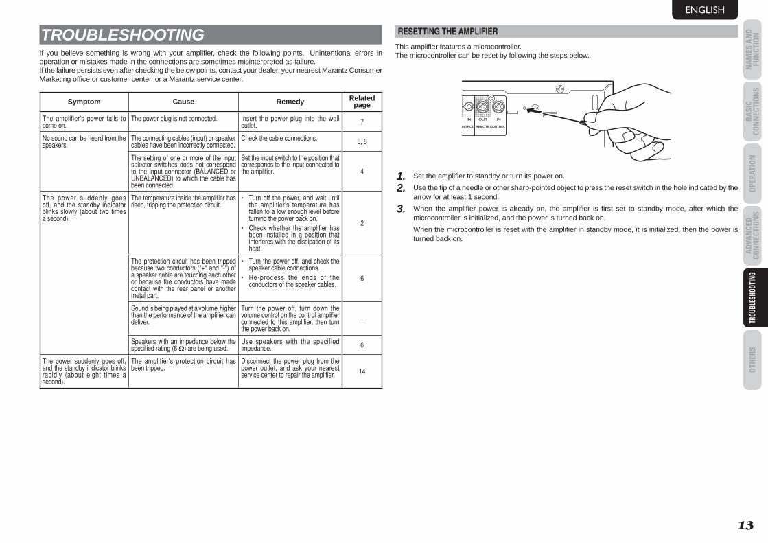
RESETTING THE AMPLIFIER
This amplifi er features a microcontroller.The microcontroller can be reset by following the steps below.
ONTROLDC CONTROL REMOTE CONTROLREMOTE CONTROL
OUT OUTOUT ININININ
1. Set the amplifi er to standby or turn its power on.
2. Use the tip of a needle or other sharp-pointed object to press the reset switch in the hole indicated by the arrow for at least 1 second.
3. When the amplifi er power is already on, the amplifi er is fi rst set to standby mode, after which the microcontroller is initialized, and the power is turned back on.
When the microcontroller is reset with the amplifi er in standby mode, it is initialized, then the power is turned back on.
MM8003_U_01_ENG.indd 13MM8003_U_01_ENG.indd 13 08.4.28 2:20:00 PM08.4.28 2:20:00 PM
BA
SIC CO
NN
ECTION
SO
PERATION
AD
VAN
CED
CON
NECTIO
NS
TROUBLESHOOTINGO
THERS
NA
MES A
ND
FU
NCTIO
NO
THERS
ENGLISH
14
OTHERS
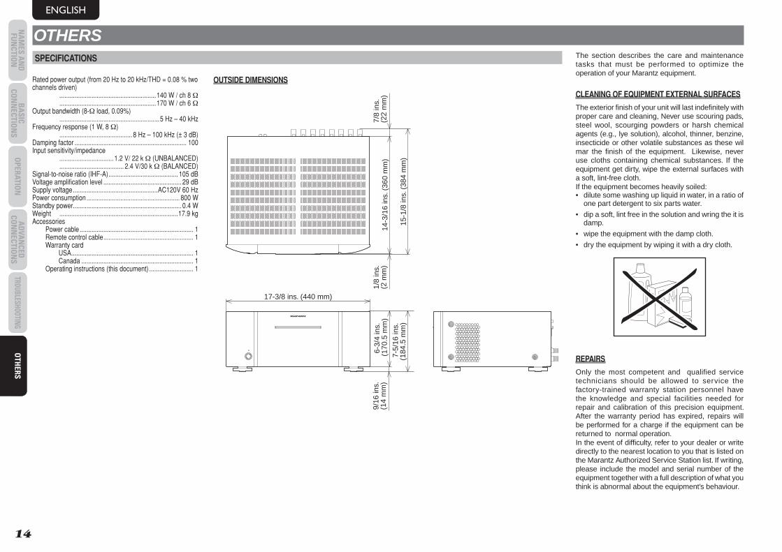
Rated power output (from 20 Hz to 20 kHz/THD = 0.08 % two channels driven) .........................................................140 W / ch 8 Ω .........................................................170 W / ch 6 ΩOutput bandwidth (8-Ω load, 0.09%) ...........................................................5 Hz – 40 kHzFrequency response (1 W, 8 Ω) ...........................................8 Hz – 100 kHz (± 3 dB)Damping factor .................................................................. 100Input sensitivity/impedance ................................1.2 V/ 22 k Ω (UNBALANCED) ...................................... 2.4 V/30 k Ω (BALANCED)Signal-to-noise ratio (IHF-A) ......................................... 105 dBVoltage amplifi cation level .............................................. 29 dBSupply voltage ..................................................AC120V 60 HzPower consumption ....................................................... 800 WStandby power ................................................................ 0.4 WWeight ......................................................................17.9 kgAccessories Power cable ................................................................... 1 Remote control cable ..................................................... 1 Warranty card USA ........................................................................ 1 Canada .................................................................. 1 Operating instructions (this document) .......................... 1
7-5
/16
ins.
(184
.5 m
m)
9/16
ins.
(14
mm
)6-
3/4
ins.
(17
0.5
mm
)
17-3/8 ins. (440 mm)
1/8
ins.
(2 m
m)
15-1
/8 in
s. (
384
mm
)
7/8
ins.
(22
mm
)14
-3/1
6 in
s. (
360
mm
)
OUTSIDE DIMENSIONS
The section describes the care and maintenance tasks that must be performed to optimize the operation of your Marantz equipment.
CLEANING OF EQUIPMENT EXTERNAL SURFACES
The exterior fi nish of your unit will last indefi nitely with proper care and cleaning, Never use scouring pads, steel wool, scourging powders or harsh chemical agents (e.g., lye solution), alcohol, thinner, benzine, insecticide or other volatile substances as these wil mar the fi nish of the equipment. Likewise, never use cloths containing chemical substances. If the equipment get dirty, wipe the external surfaces with a soft, lint-free cloth. If the equipment becomes heavily soiled: • dilute some washing up liquid in water, in a ratio of
one part detergent to six parts water.
• dip a soft, lint free in the solution and wring the it is damp.
• wipe the equipment with the damp cloth.
• dry the equipment by wiping it with a dry cloth.
REPAIRS
Only the most competent and qualified service technicians should be allowed to service the factory-trained warranty station personnel have the knowledge and special facilities needed for repair and calibration of this precision equipment. After the warranty period has expired, repairs will be performed for a charge if the equipment can be returned to normal operation. In the event of diffi culty, refer to your dealer or write directly to the nearest location to you that is listed on the Marantz Authorized Service Station list. If writing, please include the model and serial number of the equipment together with a full description of what you think is abnormal about the equipment’s behaviour.
SPECIFICATIONS
MM8003_U_01_ENG.indd 14MM8003_U_01_ENG.indd 14 08.4.28 2:20:00 PM08.4.28 2:20:00 PM

www.marantz.com You can find your nearest authorized distributor or dealer on our website.
is a registered trademark.
Printed in China 04/2008 541110074027M mzh-d
MM8003_U_00_cover.indd 2MM8003_U_00_cover.indd 2 08.4.28 2:19:35 PM08.4.28 2:19:35 PM