Embed Size (px)
Citation preview
DISASTER RESILIENCE FRAMEWORK 50% Draft for Norman, OK Workshop
20 October 2014 Communication and Information Sector, Introduction
Chapter 8, Page 1 of 39
8. Communication and Information Sector
8.1. Introduction
Communication and information systems have become increasingly critical parts of our daily lives. For example, the banking system relies on the internet for financial transactions, documents are transferred via internet between businesses and e-mail is a primary means of communication between and within companies. When the internet is not available, commerce is directly affected and economic output is reduced.
Communication and information systems have seen incredible development and use over the past 20-30 years. In terms of system types, functionality, and speed, some of the most notable changes of communication and information systems over the past few decades are:
Moving from a society that relies on fixed line (i.e., landline) telephones as the primary means of two-way voice communication to one that relies heavily on mobile devices (i.e., cell phones) and internet (Voice over Internet Protocol, VoIP) for voice communication, text messages and email. Many now have abandoned traditional landlines in favor of mobile phones and VoIP
Moving from a society where large personal computers were used to communicate via email and access information via the internet to a society where smaller mobile devices, such as laptops and cell phones, are used, constantly, for the same purpose
More and more people now use their laptops, smart phones and tablets to read news on the internet, watch movies and television shows, instead of using traditional methods such as television.
More recently, businesses have begun to use social-networking sites for collaboration, marketing, recruiting, etc.
As in many other developed countries, most people in the United States take these services for granted until they are unavailable. Unfortunately, communication and information systems are often lost in the wake of natural disasters – a time when they are needed most for:
1. Relaying emergency and safety information to the public 2. Coordinating recovery plans among first responders and community leaders 3. Communication between family members and loved ones to check on each other’s safety 4. Communication between civilians and emergency responders 5. Communication between emergency responders in the field
When addressing resilience, communities must also think about the longer term and improving performance of the built environment in the next disaster event. The intermediate and long term needs of communities, in terms of communications and information infrastructure, include:
1. Ability to communicate with employers, schools and other aspects of individuals’ daily lives 2. Re-establishing operations of small businesses, banks, etc., via internet and telecommunications so
they can serve their clients. 3. Restoration, retrofits, and improvements to components of the infrastructure so it will not fail in the
same way in future events (i.e., implement changes to make infrastructure more resilient)
This chapter addresses disaster resilience of communication and information systems. The first steps for a community to address resilience of their infrastructure are to identify the regulatory bodies, parties responsible for condition and maintenance of the infrastructure, work with the stakeholders to determine the performance goals of the infrastructure, evaluate the state of the existing communication and information infrastructure systems, identify the weak links in the infrastructure network and prioritize upgrades to improve resilience of the network. This chapter discusses a performance goals table specific to the communications infrastructure system, and illustrates how a performance goals table can be used by
DISASTER RESILIENCE FRAMEWORK 50% Draft for Norman, OK Workshop
20 October 2014 Communication and Information Sector, Introduction
Chapter 8, Page 2 of 39
communities to set their performance goals for various hazards. This chapter also lists stakeholders/owners of the various components of communications infrastructure, discusses critical infrastructure of various communication and information systems, and recommends improvements that can be made to enhance the resilience of the system.
8.1.1. Social Needs and System Performance Goals
As discussed in Chapter 3, the social needs of the community drive the performance goals that are to be defined by each community and its stakeholders. The social needs of the community include those of citizens, businesses (both small/local and large/multi-national), industry, and government. Each community should define its performance goals in terms of the time it takes for its critical infrastructure to be restored following a disaster event for three levels of event: routine, expected, and extreme, as defined in Chapter 3.
The community has short (1-3 days), intermediate (1-12 weeks) and long term (4-36 months) recovery needs. Specific to communications, communities traditionally think about recovery in terms of emergency response and management goals, which includes communication between:
1. Citizens and emergency responders 2. Family members and loved ones to check on each other’s safety 3. Government and the public (e.g., providing emergency and safety information to the public) 4. First responders 5. Government agencies
However, as discussed in the introductory section, communities must think about their long term social needs when addressing resilience. The intermediate goals of the community are to recover so that people and businesses can return to their daily routine. To do this, people need to be able to communicate with their employers, their children’s schools, and other members of the community, businesses need to have internet and telephone service to communicate with their clients and suppliers. In the long term, communities should strive to go beyond simply recovering by prioritizing and making improvements to parts of the communications infrastructure that failed in the disaster.
8.1.2. Reliability v. Resilience
The communications industry typically thinks about service to customers in terms of reliability. Reliability is the ability to provide a consistent level of service to end users (i.e., reliable networks have infrequent outages). Whether the type of communications system is wireline or wireless telephone, or internet, service providers market their reliability to potential customers. Service providers think about the communications system itself in terms of the service(s) they provide to the end user rather than the infrastructure (i.e., built environment) that supports the service.
Resilience is similar to reliability, though they are not exactly the same. Like reliability, resilience includes the ability to withstand disruptions. However, resilience also involves preparing for and adapting to changing conditions to mitigate the impacts of future events so that disruptions occur less frequently, and, when they do occur, there is a plan to recover quickly. Resilience is also the ability to recover from a disaster event such that the infrastructure is rebuilt to a higher standard. Consequently, by enhancing the resilience of communications infrastructure, the reliability of the communications network can be improved.
Capacity. The resilience and resulting reliability of communications infrastructure are dependent on the capacity of the network. As is often seen during and immediately after disaster events, there is an increase in demand of the communication and information systems (Jrad et al. 2005 and 2006). Section 8.1 points out that, during and immediately after a disaster event, the system is used extensively for communication
DISASTER RESILIENCE FRAMEWORK 50% Draft for Norman, OK Workshop
20 October 2014 Communication and Information Sector, Introduction
Chapter 8, Page 3 of 39
between family and loved ones, communication with vulnerable populations (such as the ill or elderly), communication between civilians and first responders, as well as communication between customers and service providers when outages occur. Unfortunately, the capacity of systems is not increased for disasters and so cellular phones, for example, may not function properly due to high volume use. This is especially true in densely populated areas, which may be located in large urban areas, such as New York City or around emergency shelter or evacuation areas. The latter is an especially important consideration, because some facilities used as emergency shelter and evacuation centers are not designed with that intent. For example, the Superdome in New Orleans, LA was used as emergency shelter during Hurricane Katrina. Although this is an exceptionally large facility used for sporting and entertainment events, and may have above average capacity, these facilities can be overwhelmed prior to, during and after disaster events because of the large influx of civilians seeking shelter, which results in a large demand on the wireless/cellular network. With the expansion of technology and the massive growth of cellular phone use, the wireless telecommunications network around emergency shelter facilities will become more stressed in disaster events.
Jrad et al. (2005) found that for an overall telecommunications infrastructure network to be most resilient, an approximately equal user base for wireline and wireless communications was best. The study found that if one network is significantly greater than the other and the larger one experiences a disruption, increased demand will switch to the smaller network and lead to overload. For example, if the landline demand is 1,000,000 users, the cellular network demand is 500,000 users, and the landline network experiences a disruption in a disaster event, some of the landline demand will transfer to the cellular network (Jrad et al. 2005). The increased demand would then put stress on the wireless network and likely result in service disruptions due to overloading of the network.
8.1.3. Interdependencies
Chapter 4 provides details of the interdependencies of all critical infrastructure systems in a community. The built environment within communities is continually becoming more complex and different systems are becoming more dependent on one another to provide services. Specific to the communications and information system, the following interdependencies must be considered:
1. Power/Energy – The communication and information system is highly dependent on the power/energy system. For current high technology and data services, the end user needs external power for telecommunications, internet, and cable. Loss of external power means loss of communication/information services, except for cellular phones which will likely be able to function until their battery is used. Furthermore, distribution of communications and power service is often co-located (e.g., wires traveling along utility poles). Failure of these systems can happen simultaneously due to tree fall severing both types of lines. In the wake of a disaster event where external power is lost, communications infrastructure needs standby power to ensure continued functionality. Conversely, emergency repair crews for power utilities need to be able to communicate so they can get prioritize and repair their network efficiently. The power provider controls the rights of the utility poles, and thus the design, construction, routing and maintenance of telecommunication lines are dependent on the requirements of the power utility provider requirements and regulations.
2. Transportation – As will be discussed in this chapter, one problem commonly seen after disaster events is that roadways and other parts of the transportation system needed in recovery of lifelines become impassible. Specifically, tree fall and other debris resulting from high wind events (e.g., hurricanes and tornadoes), storm surge/flooding, and ice storms prevent emergency crews from reaching the areas they need to repair damaged communications infrastructure. On the other hand, transportation repair crews, including those for traffic signals, need to be able to communicate to ensure their system is fixed.
DISASTER RESILIENCE FRAMEWORK 50% Draft for Norman, OK Workshop
20 October 2014 Communication and Information Sector, Critical Communication and Information Infrastructure
Chapter 8, Page 4 of 39
3. Building/Facilities – Buildings and facilities need their communications and information systems to function properly. Buildings used for business and industry communicate with clients, suppliers, and each other via telephone and email. Residential buildings need these services to communicate with employers, loved ones, banks, and services. Currently, money is transferred between businesses, bills are paid to services/businesses and personal banking is completed online or, less commonly, by telephone.
Individuals inside buildings in the immediate aftermath of sudden, unexpected events (e.g., blast events) also need the communications network to learn what is happening.
4. Water and Wastewater – Water and wastewater utilities rely on communications amongst operations staff and emergency workers in the recovery phase. If the communications network, including the cellular network, is down for an extended period of time following a disaster event, the recovery process can take longer since there will be limited to no coordination in the efforts.
5. Security – Although security is not addressed as a sector in this framework, it is an important consideration, particularly in the immediate (emergency) recovery after a disaster event. Service providers will not endanger employees. In cases where power and communications systems fail, security becomes an issue because (small groups of) citizens may use it as an opportunity for looting and violence. Therefore, communication and information service providers must be able to work with security to control the situation and begin the recovery process in a timely manner.
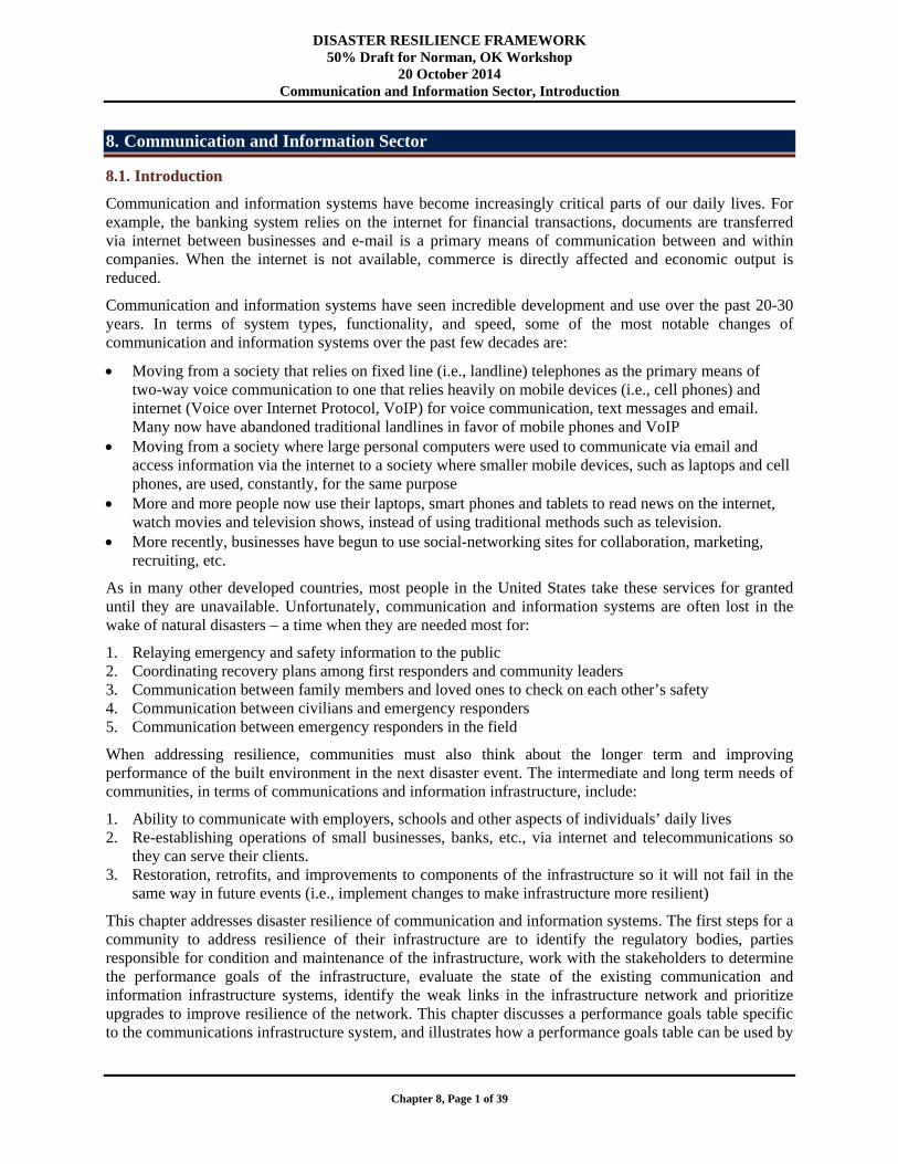
8.2. Critical Communication and Information Infrastructure
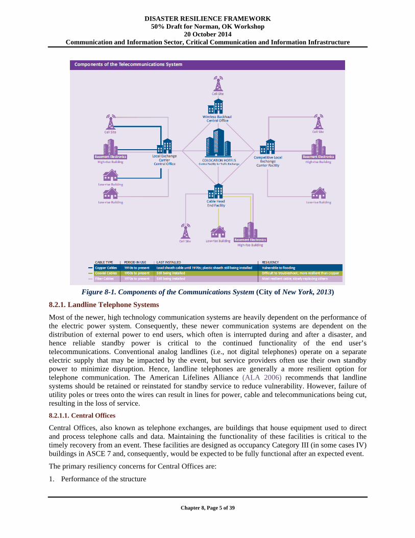
There are a number of critical components in the communication and information system infrastructure. This section discusses some of these infrastructure components, their potential vulnerabilities, and strategies used in the past to successfully mitigate failures. Figure 8-1 presents components of a telecommunications system.
DISASTER RESILIENCE FRAMEWORK 50% Draft for Norman, OK Workshop
20 October 2014 Communication and Information Sector, Critical Communication and Information Infrastructure
Chapter 8, Page 5 of 39
Figure 8-1. Components of the Communications System (City of New York, 2013)
8.2.1. Landline Telephone Systems
Most of the newer, high technology communication systems are heavily dependent on the performance of the electric power system. Consequently, these newer communication systems are dependent on the distribution of external power to end users, which often is interrupted during and after a disaster, and hence reliable standby power is critical to the continued functionality of the end user’s telecommunications. Conventional analog landlines (i.e., not digital telephones) operate on a separate electric supply that may be impacted by the event, but service providers often use their own standby power to minimize disruption. Hence, landline telephones are generally a more resilient option for telephone communication. The American Lifelines Alliance (ALA 2006) recommends that landline systems should be retained or reinstated for standby service to reduce vulnerability. However, failure of utility poles or trees onto the wires can result in lines for power, cable and telecommunications being cut, resulting in the loss of service.
8.2.1.1. Central Offices
Central Offices, also known as telephone exchanges, are buildings that house equipment used to direct and process telephone calls and data. Maintaining the functionality of these facilities is critical to the timely recovery from an event. These facilities are designed as occupancy Category III (in some cases IV) buildings in ASCE 7 and, consequently, would be expected to be fully functional after an expected event.
The primary resiliency concerns for Central Offices are:
1. Performance of the structure
DISASTER RESILIENCE FRAMEWORK 50% Draft for Norman, OK Workshop
20 October 2014 Communication and Information Sector, Critical Communication and Information Infrastructure
Chapter 8, Page 6 of 39
2. Redundancy of Central Offices/Nodes within Network 3. Placement/security of critical equipment 4. Threat to/from interdependent services
Performance of the Structure. The design of Central Offices is extremely important for continued service of the telecommunications system. Depending on the location of the community, the design considers different types and magnitudes of disasters. These buildings are to be designed as an Occupancy Category III building per ASCE 7, and consequently the design of equipment and standby power must be consistent with that of the building design.
For example, the design of Central Offices in California may be mainly concerned with earthquake loading, whereas Central Offices on the east coast may be concerned mainly with hurricane force winds and/or flooding (especially if it is located in the floodplain as are many Central Offices in coastal communities). In place of providing redundancy of Central Offices (see discussion in next section), these structures should be designed to resist more extreme environmental loads. In cases where Central Offices are located in older buildings, built to codes and standards that are less stringent than current day standards, it is important to bring these buildings up to modern standards or harden the sections of the building containing critical telecommunications equipment to achieve the desired performance level.
Partial failure of a Central Office can result in the loss of switches and other critical equipment, which results in damage to the communications infrastructure network and loss of functionality. On September 11, 2001 (9-11), four switches were lost in the Verizon Central Office located at 140 West Street (Jrad et al. 2006).
Complete collapse of a Central Office or other building containing a node/exchange in the network would result in loss of all switches and critical equipment. On 9-11, two switches were lost in the World Trade Center Buildings that collapsed (Jrad et al 2006). Though these were not Central Offices, the loss of the nodes could not be recovered. The loss of an entire Central Office would bring the service provider’s network to a halt, particularly if no redundancy was built into the network of Central Offices as will be discussed in the following section.
Since communities are ultimately responsible for the updating, enforcing and making amendments to building codes, it is important that the most up-to-date building codes be used in the design of new buildings that are used as a part of the communication network. In cases where existing buildings house Central Offices, it is recommended that these buildings are evaluated and hardened as needed to ensure that the critical equipment within the structure is protected.
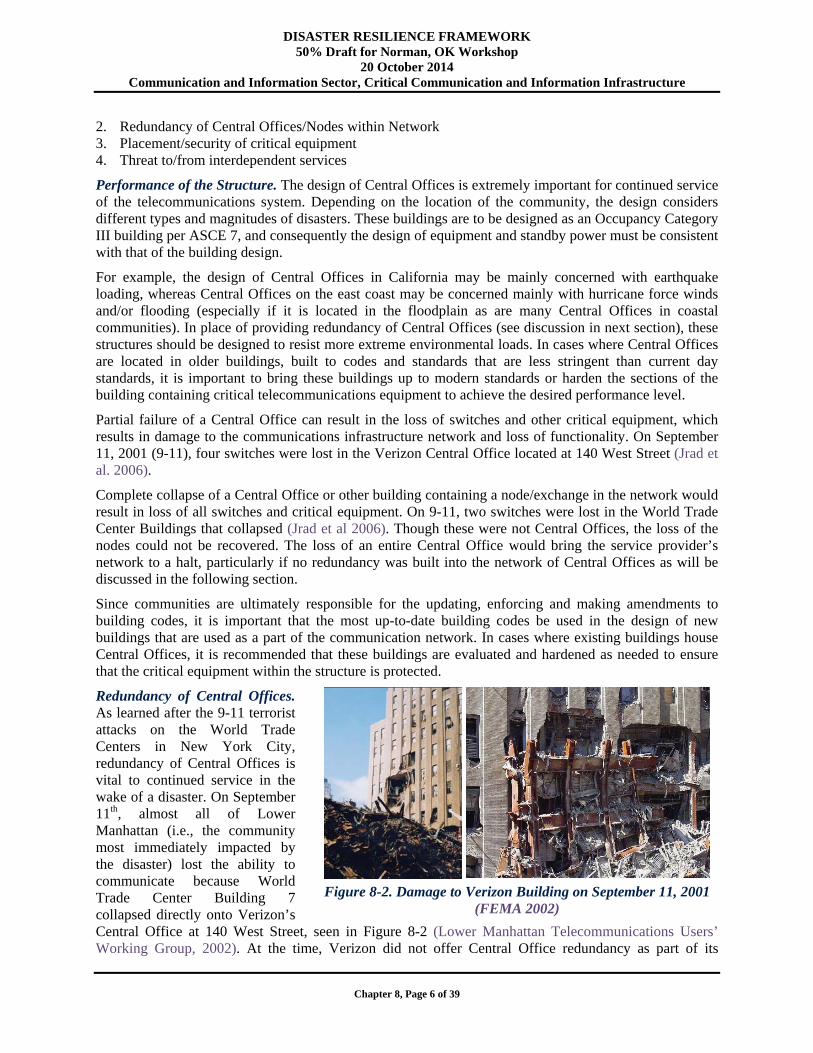
Redundancy of Central Offices. As learned after the 9-11 terrorist attacks on the World Trade Centers in New York City, redundancy of Central Offices is vital to continued service in the wake of a disaster. On September 11th, almost all of Lower Manhattan (i.e., the community most immediately impacted by the disaster) lost the ability to communicate because World Trade Center Building 7 collapsed directly onto Verizon’s Central Office at 140 West Street, seen in Figure 8-2 (Lower Manhattan Telecommunications Users’ Working Group, 2002). At the time, Verizon did not offer Central Office redundancy as part of its
Figure 8-2. Damage to Verizon Building on September 11, 2001
(FEMA 2002)
DISASTER RESILIENCE FRAMEWORK 50% Draft for Norman, OK Workshop
20 October 2014 Communication and Information Sector, Critical Communication and Information Infrastructure
Chapter 8, Page 7 of 39
standard service. Furthermore, customers of other carriers/service providers that leased Verizon’s space lost service as well since they did not provide redundancy either. Verizon made a significant effort to restore their services rapidly after the attacks and have since improved their system to use multiple Central Offices for additional reliability. AT&T also endured problems as they had two transport nodes located in World Trade Tower 2, which collapsed. Overall, almost $2 billion was spent on rebuilding and upgrading Lower Manhattan’s telecom infrastructure after 9-11 (Lower Manhattan Telecommunications Users’ Working Group, 2002).
Although this was an extremely expensive venture, it is an example that shows building a telecom system with redundancy can eliminate expensive upgrading/repair costs after a disaster event. However, this magnitude of expense is likely not necessary for many other communities.
Placement/Security of Critical Equipment. Although construction of the building is important; placement and security of equipment is also an essential consideration if functionality is to be maintained. For example, any electrical or standby power equipment, such as generators, should be placed above the extreme (as defined in Chapter 3) flood level scenario, but should also be located such that it is not susceptible to other environmental loads such as wind. The flooding produced by Hurricane Sandy, exposed weaknesses in the location of standby power (e.g., generators). Generators and other electrical equipment that were placed in basements failed due to flooding (FEMA 2013).
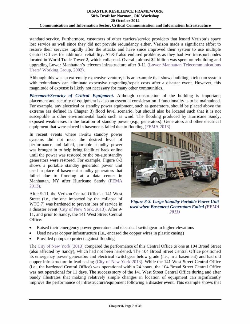
In recent events where in-situ standby power systems did not meet the desired level of performance and failed, portable standby power was brought in to help bring facilities back online until the power was restored or the on-site standby generators were restored. For example, Figure 8-3 shows a portable standby generator power unit used in place of basement standby generators that failed due to flooding at a data center in Manhattan, NY after Hurricane Sandy (FEMA 2013).
After 9-11, the Verizon Central Office at 141 West Street (i.e., the one impacted by the collapse of WTC 7) was hardened to prevent loss of service in a disaster event (City of New York, 2013). After 9-11, and prior to Sandy, the 141 West Street Central Office:
Raised their emergency power generators and electrical switchgear to higher elevations Used newer copper infrastructure (i.e., encased the copper wires in plastic casing) Provided pumps to protect against flooding
The City of New York (2013) compared the performance of this Central Office to one at 104 Broad Street (also affected by Sandy), which had not been hardened. The 104 Broad Street Central Office positioned its emergency power generators and electrical switchgear below grade (i.e., in a basement) and had old copper infrastructure in lead casing (City of New York 2013). While the 141 West Street Central Office (i.e., the hardened Central Office) was operational within 24 hours, the 104 Broad Street Central Office was not operational for 11 days. The success story of the 141 West Street Central Office during and after Sandy illustrates that making relatively simple changes in location of equipment can significantly improve the performance of infrastructure/equipment following a disaster event. This example shows that
Figure 8-3. Large Standby Portable Power Unit used when Basement Generators Failed (FEMA
2013)
DISASTER RESILIENCE FRAMEWORK 50% Draft for Norman, OK Workshop
20 October 2014 Communication and Information Sector, Critical Communication and Information Infrastructure
Chapter 8, Page 8 of 39
careful planning of critical equipment location and protection is essential to achieving the performance goal of continued service in the wake of a disaster event.
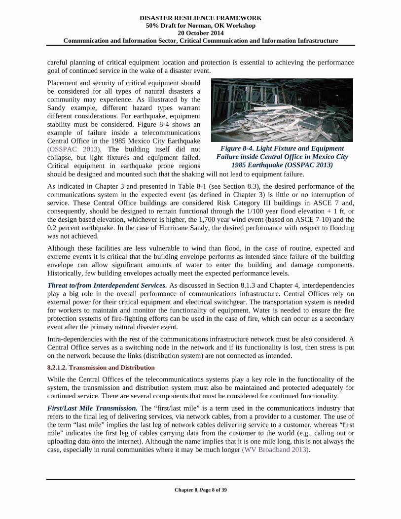
Placement and security of critical equipment should be considered for all types of natural disasters a community may experience. As illustrated by the Sandy example, different hazard types warrant different considerations. For earthquake, equipment stability must be considered. Figure 8-4 shows an example of failure inside a telecommunications Central Office in the 1985 Mexico City Earthquake (OSSPAC 2013). The building itself did not collapse, but light fixtures and equipment failed. Critical equipment in earthquake prone regions should be designed and mounted such that the shaking will not lead to equipment failure.
As indicated in Chapter 3 and presented in Table 8-1 (see Section 8.3), the desired performance of the communications system in the expected event (as defined in Chapter 3) is little or no interruption of service. These Central Office buildings are considered Risk Category III buildings in ASCE 7 and, consequently, should be designed to remain functional through the 1/100 year flood elevation + 1 ft, or the design based elevation, whichever is higher, the 1,700 year wind event (based on ASCE 7-10) and the 0.2 percent earthquake. In the case of Hurricane Sandy, the desired performance with respect to flooding was not achieved.
Although these facilities are less vulnerable to wind than flood, in the case of routine, expected and extreme events it is critical that the building envelope performs as intended since failure of the building envelope can allow significant amounts of water to enter the building and damage components. Historically, few building envelopes actually meet the expected performance levels.
Threat to/from Interdependent Services. As discussed in Section 8.1.3 and Chapter 4, interdependencies play a big role in the overall performance of communications infrastructure. Central Offices rely on external power for their critical equipment and electrical switchgear. The transportation system is needed for workers to maintain and monitor the functionality of equipment. Water is needed to ensure the fire protection systems of fire-fighting efforts can be used in the case of fire, which can occur as a secondary event after the primary natural disaster event.
Intra-dependencies with the rest of the communications infrastructure network must be also considered. A Central Office serves as a switching node in the network and if its functionality is lost, then stress is put on the network because the links (distribution system) are not connected as intended.
8.2.1.2. Transmission and Distribution
While the Central Offices of the telecommunications systems play a key role in the functionality of the system, the transmission and distribution system must also be maintained and protected adequately for continued service. There are several components that must be considered for continued functionality.
First/Last Mile Transmission. The “first/last mile” is a term used in the communications industry that refers to the final leg of delivering services, via network cables, from a provider to a customer. The use of the term “last mile” implies the last leg of network cables delivering service to a customer, whereas “first mile” indicates the first leg of cables carrying data from the customer to the world (e.g., calling out or uploading data onto the internet). Although the name implies that it is one mile long, this is not always the case, especially in rural communities where it may be much longer (WV Broadband 2013).
Figure 8-4. Light Fixture and Equipment
Failure inside Central Office in Mexico City 1985 Earthquake (OSSPAC 2013)
DISASTER RESILIENCE FRAMEWORK 50% Draft for Norman, OK Workshop
20 October 2014 Communication and Information Sector, Critical Communication and Information Infrastructure
Chapter 8, Page 9 of 39
As was learned from the 9-11 attacks, the first/last mile is a key to resilience for telecommunications and information infrastructure, especially for downtown business telecom networks. In urban settings, service providers typically connect the Central Offices in a ring, which connects to the internet backbone at several points (Lower Manhattan Telecommunications Users’ Working Group, 2002). Although, the first/last mile is beyond this ring of Central Offices, the redundancy results in a resilient method that improves the likelihood that service providers will achieve their systems performance goal of continual service because path diversity is built into the infrastructure system often using nodes that connect to the internet backbone. However, as was learned during workshops used to inform this framework, part of the last mile typically does not connect to the internet backbone and, thus, is vulnerable to single-point failures. Furthermore, the location of the node failure also impacts service. If the failed node is between a Central Office and the buildings/facilities it services (i.e., the first/last mile) then the first/last mile customers will be of service.
In rural communities, there is likely to be less redundancy in the telecommunication and information network cable systems. Historically, rural and remote communities have not used these services as frequently or relied as heavily on them as urban communities. This has been the case because: 1) In the past, the technology to send large amounts of data over a long distance had not been available; and 2) The cost for service providers to expand into remote communities may be too high and have a low benefit-cost ratio. As a result of the lack of redundancy in rural and remote communities, a failure of one node in the service cables (single point of failure) may be all that is necessary for an outage to occur. Therefore, it may not be practical, currently, for rural and remote communities to expect the same performance goals as urban communities. However, as communications technology continues to grow and change, the level of redundancy (or path diversity) in communications infrastructure delivering services to rural/remote communities is likely to increase. Furthermore, in the case where the reason for loss of telecommunication services in the loss of external power rather than failure of the communications system itself, restoration of services may be quicker for rural communities. As was learned in the stakeholder workshops held to inform this framework, it was observed in Hurricanes Katrina and Sandy that power can be easier to restore in rural areas because in densely populated areas, components tend to be “packed-in” tightly and other systems need to be repaired first before getting to the power supply system.
Copper Wires. Copper wires work by transmitting signals through electric pulses and carry the low power needed to operate a traditional landline telephone. The telephone company (i.e., service provider) that owns the wire provides the power rather than an electric company. Therefore, the use of traditional analog (i.e., plain old telephone service or POTS) landlines that use copper wire lessens the interdependency on external power (ALA 2006). As a result, in a natural disaster event resulting in loss of external power, communication may, but is not guaranteed to, still be possible through the use of analog landlines.
Although copper wires perform well in many cases, they are being replaced more and more by fiber optic cables because copper wires cannot support the large amount of data required for television and high-speed internet, which has become the norm in the 21st century (Lower Manhattan Telecommunications Users’ Working Group 2002).
Some service providers are interested in retiring their copper wires. Keeping both fiber optic and copper wires in service makes maintenance expensive for service providers and, hence, for customers (FTTH Council 2013). Copper wire is an aging infrastructure that becomes increasingly expensive to maintain. Verizon has reported that its operating expenses have been reduced by approximately 70% when it installed its FiOS (fiber optic) network and retired its copper plant in Central Offices (FTTH Council 2013).
Despite the advantages of traditional copper wire, there are also well-documented problems. As seen during and after Hurricane Sandy, copper wire is susceptible to salt water flooding. Once these metal
DISASTER RESILIENCE FRAMEWORK 50% Draft for Norman, OK Workshop
20 October 2014 Communication and Information Sector, Critical Communication and Information Infrastructure
Chapter 8, Page 10 of 39
wires are exposed to salt water, they fail (City of New York 2013). One solution to this problem is to ensure that the copper wire is encased in a plastic or another non-saltwater sensitive material. Furthermore, copper wires are older and generally, are no longer installed.
Coaxial Cables. Coaxial cable is a more modern material and commonly used for transmission. It offers more resistance to water and is, therefore, not as susceptible to flood damage as copper wires. After Sandy, these coaxial wires generally performed well with failures typically associated with loss of power to the electrical equipment to which they were connected (City of New York 2013). Coaxial cable has been and continues to be primarily used for cable television and internet services. However, coaxial cables are being replaced more and more by fiber optic cable since fiber optic cables can carry all types of services.
Fiber Optic Cables. Fiber optic cables are more resistant to water damage than either coaxial cable or copper wire (City of New York 2013). Fiber optic cables are now commonly used to bundle home services (television, high-speed internet, and telephone) into one system, and to provide ultra-high speed internet. The use of fiber optic cables allows for transmission of large amounts of data on a single fiber. These cables are fully water resistant (City of New York 2013). Unfortunately, these services rely more heavily on power provided by a power company instead of the communications provider itself for the end user. Consequently, during and after a natural disaster event where power is frequently interrupted, landline communications using fiber optic cables are lost (ALA 2006). In fact, some communities turn off the power prior to the arrival of hurricane force winds for safety purposes. This prevents “live” electric lines from falling on roads, homes, etc., but it also eliminates the external power source for telecommunications of the end user. Some service providers provide in-home battery backup for cable and telephone.
Overhead vs. Underground Wires. Transmission wire can be strung overhead using utility poles or run underground. There are advantages and disadvantages for both options.
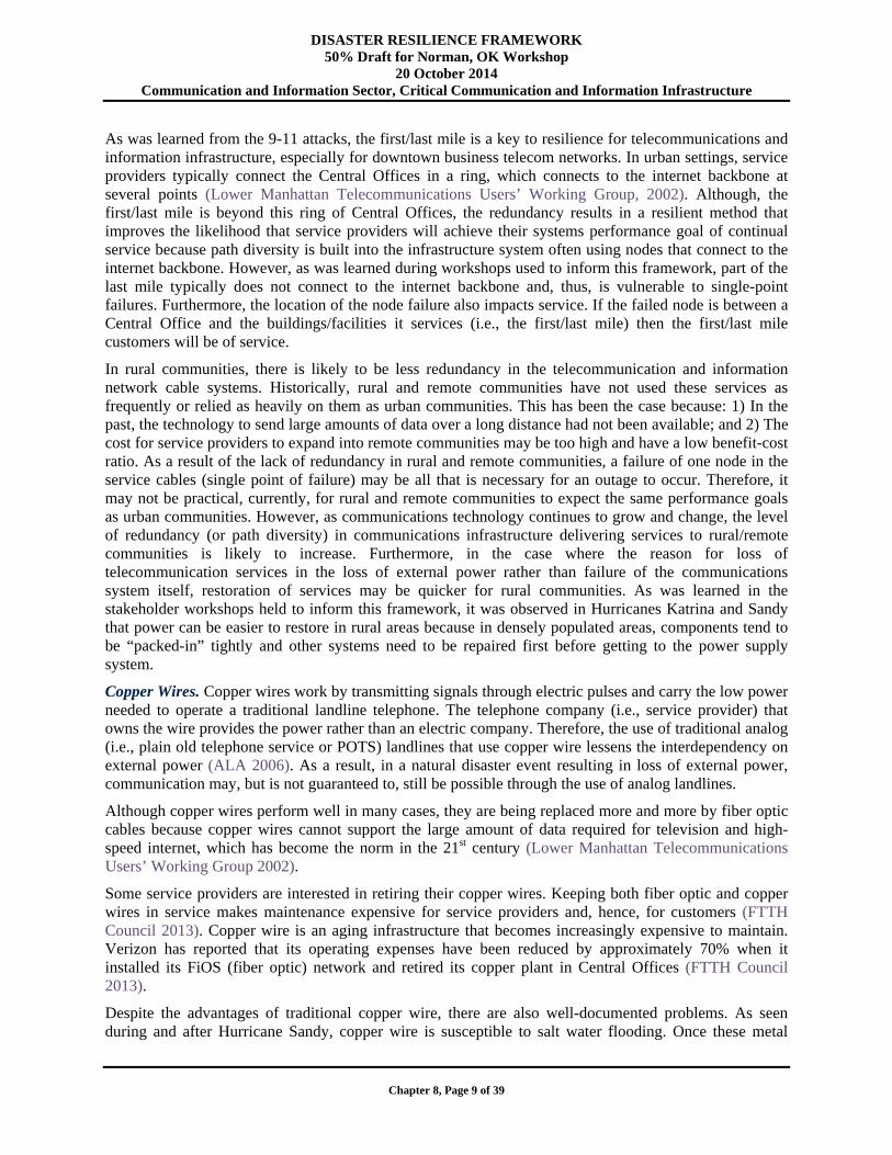
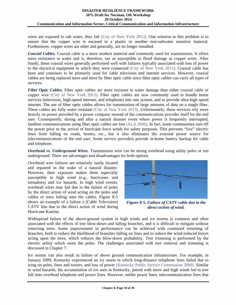
Overhead wire failures are relatively easily located and repaired in the wake of a natural disaster. However, their exposure makes them especially susceptible to high wind (e.g., hurricanes and tornadoes) and ice hazards. In high wind events, overhead wires may fail due to the failure of poles by the direct action of wind acting on the poles and cables or trees falling onto the cables. Figure 8-5 shows an example of a failure a (Cable Television) CATV line due to the direct action of wind during Hurricane Katrina.
Widespread failure of the above-ground system in high winds and ice storms is common and often associated with the effects of tree blow-down and falling branches, and it is difficult to mitigate without removing trees. Some improvement in performance can be achieved with continued trimming of branches, both to reduce the likelihood of branches falling on lines and to reduce the wind-induced forces acting upon the trees, which reduces the blow-down probability. Tree trimming is performed by the electric utility which owns the poles. The challenges associated with tree removal and trimming is discussed in Chapter 7.
Ice storms can also result in failure of above ground communication infrastructure. For example, in January 2009, Kentucky experienced an ice storm in which long-distance telephone lines failed due to icing on poles, lines and towers, and loss of power (Kentucky Public Service Commission 2009). Similar to wind hazards, the accumulation of ice seen in Kentucky, paired with snow and high winds led to tree fall onto overhead telephone and power lines. However, unlike power lines, telecommunication lines that
Figure 8-5. Failure of CATV cable due to the
direct action of wind.
DISASTER RESILIENCE FRAMEWORK 50% Draft for Norman, OK Workshop
20 October 2014 Communication and Information Sector, Critical Communication and Information Infrastructure
Chapter 8, Page 11 of 39
have limbs hanging on them or fall to the ground will continue to function unless severed (Kentucky Public Service Commission 2009). Since long-distance telecommunications depend on power from another source (i.e., power providers), communication with those outside the local community were lost during the storm. Following the 2009 Kentucky ice storm, many communities became isolated and were unable to communicate their situation and emergency needs to regional or state disaster response officials (Kentucky Public Service Commission 2009). However, as learned from workshops held to inform this framework, long distance communications do have standby power capability.
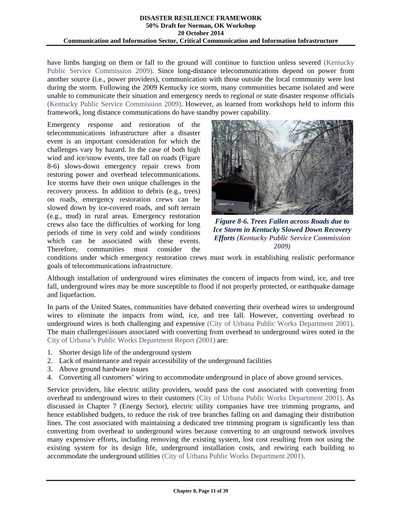
Emergency response and restoration of the telecommunications infrastructure after a disaster event is an important consideration for which the challenges vary by hazard. In the case of both high wind and ice/snow events, tree fall on roads (Figure 8-6) slows-down emergency repair crews from restoring power and overhead telecommunications. Ice storms have their own unique challenges in the recovery process. In addition to debris (e.g., trees) on roads, emergency restoration crews can be slowed down by ice-covered roads, and soft terrain (e.g., mud) in rural areas. Emergency restoration crews also face the difficulties of working for long periods of time in very cold and windy conditions which can be associated with these events. Therefore, communities must consider the conditions under which emergency restoration crews must work in establishing realistic performance goals of telecommunications infrastructure.
Although installation of underground wires eliminates the concern of impacts from wind, ice, and tree fall, underground wires may be more susceptible to flood if not properly protected, or earthquake damage and liquefaction.
In parts of the United States, communities have debated converting their overhead wires to underground wires to eliminate the impacts from wind, ice, and tree fall. However, converting overhead to underground wires is both challenging and expensive (City of Urbana Public Works Department 2001). The main challenges\issues associated with converting from overhead to underground wires noted in the City of Urbana’s Public Works Department Report (2001) are:
1. Shorter design life of the underground system 2. Lack of maintenance and repair accessibility of the underground facilities 3. Above ground hardware issues 4. Converting all customers’ wiring to accommodate underground in place of above ground services.
Service providers, like electric utility providers, would pass the cost associated with converting from overhead to underground wires to their customers (City of Urbana Public Works Department 2001). As discussed in Chapter 7 (Energy Sector), electric utility companies have tree trimming programs, and hence established budgets, to reduce the risk of tree branches falling on and damaging their distribution lines. The cost associated with maintaining a dedicated tree trimming program is significantly less than converting from overhead to underground wires because converting to an unground network involves many expensive efforts, including removing the existing system, lost cost resulting from not using the existing system for its design life, underground installation costs, and rewiring each building to accommodate the underground utilities (City of Urbana Public Works Department 2001).
Figure 8-6. Trees Fallen across Roads due to
Ice Storm in Kentucky Slowed Down Recovery Efforts (Kentucky Public Service Commission
2009)

DISASTER RESILIENCE FRAMEWORK 50% Draft for Norman, OK Workshop
20 October 2014 Communication and Information Sector, Critical Communication and Information Infrastructure
Chapter 8, Page 12 of 39
8.2.2. Internet Systems
The internet has become the most used source of one and two-way communication over the past couple of decades. It is continually used for email, online shopping, receiving/reading the news, telephony, and increasingly for use of social-networking. Businesses rely heavily on the internet for communication, sending and receiving documents, video conferencing, email, and working with other team members using online collaboration tools. The internet is heavily used by financial institutions for transferring funds, buying and selling stocks, etc. As healthcare moves towards electronic medical records, connectivity becomes more important in the healthcare system.
High-speed internet is often tied in with telephone and cable by service providers through coaxial or fiber optic wires. The internet depends on the electric power system, and loss of power at any point along the chain from source to user prevents data reception. As a result, internet dependency on the electric power system makes it vulnerable to the performance of the power system in a natural disaster event. A concern for internet systems, as is the case for landlines, is single points of failure (i.e., an individual source of service where there is no alternative/redundancy).
8.2.2.1. Internet Exchange Points (IXP)
Internet Exchange Points are buildings that allow service providers to connect directly to each other. This is advantageous because it helps improve quality of service and reduce transmission costs. The development of IXPs has played a major role in advancing development of the internet ecosystem across North America, Europe, and Asia (Kende and Hurpy, 2012). IXPs now also stretch into several countries in Africa and continue to expand the reach of the Internet. IXPs facilitate local, regional, and international connectivity.
IXPs provide a way for members, including Internet Service Providers (ISPs), backbone providers and content providers to connect their networks and exchange traffic directly (Kende and Hurpy 2012). Similarly to Central Offices for landlines, this results in IXPs being a potential single point of failure.
The buildings housing the IXPs would be expected to meet the ASCE 7 requirements for critical buildings (Occupancy Category IV) and, consequently, would be expected to perform with no interruption of service for the “expected” event, or hazard level. The facilities would be expected to have sufficient standby power to function until external power to the facility is brought back online.
Location of Critical Equipment in IXPs. Another similarity to telecommunications Central Offices is that the location and protection of critical equipment is important. Critical equipment should be protected by placing it in locations where it will not be susceptible to expected hazards in the community. For example, inevitably some of these buildings will be or have been built in floodplains because many large urban centers are centered around large bodies of water or on the coast. The owner, engineers, maintenance, and technical staff must all be aware of potential hazards that could impact the equipment within the structure. As should be done for telecommunications Central Offices, the following considerations should be taken into consideration for the critical equipment of IXPs:
Electrical and emergency equipment should be located above the elevation of an “extreme” flood, which is to be defined by the community (see Chapter 3).
Rooms housing critical equipment should be designed to resist the extreme loads for the community, whether it is earthquake, high wind, blast, other hazards, or a combination of hazards. Remember that fire is often a secondary hazard that results from other disaster events.
Where possible, redundancy and standby power for critical equipment should be provided.
All too often, communities have seen the same problems and damage in the wake of a natural disaster event (e.g., loss of power, loss of roof cover and wall cladding leading to rain infiltration in high wind events). Fortunately, many problems can be mitigated by sufficient planning and risk assessment. As
DISASTER RESILIENCE FRAMEWORK 50% Draft for Norman, OK Workshop
20 October 2014 Communication and Information Sector, Critical Communication and Information Infrastructure
Chapter 8, Page 13 of 39
previously discussed, an example was the comparison of two telecommunications Central Offices in New York City after Hurricane Sandy. Careful placement and protection of critical equipment can help to achieve the performance goals of the internet’s critical equipment. For example, in flood prone regions, critical equipment should be placed above the extreme flood level for the area. In earthquake regions, critical equipment should be designed and mounted such that shaking from earthquake events does not cause failure.
8.2.2.2. Internet Backbone
The Internet Backbone refers to the cables that connect the “network-of-networks.” The Internet is a system of nodes connected by paths/links. These paths run all over the United States and the rest of the world. As a result, many of the same challenges identified for the landline cables for fiber optic cables exist for internet, namely that it requires power to function. The heavy reliance on power impacts the performance and recovery goals of internet service for service providers and their customers.
Path Diversity. Path diversity refers to the ability of information to travel along different paths to get to its destination should there be a failure in its originally intended path (i.e., path diversity is synonym of redundancy). The more diversity that exists, the more reliable the system will be.
8.2.3. Cellular/Mobile Systems
The cellular telephone system has most of the same vulnerabilities as the landline system, including the local exchange offices, collocation hotels, and cable head facilities. Other possible failure points unique to the cellular network include the cell site (tower and power) and wireless backhaul Central Offices. Figure 8-1 shows how the cellular phone network fits within the telecommunication network. At the base of a cell tower is switchgear (also known as Cell Site Electronics) and standby power. Damage of switchgear at the base of the tower prevents switching to standby power when commercial power fails.
8.2.3.1. Cell Towers
Virtually all natural hazards including earthquake, high wind, ice and flood affect the ability of an individual cell tower to function through one or more of the following.
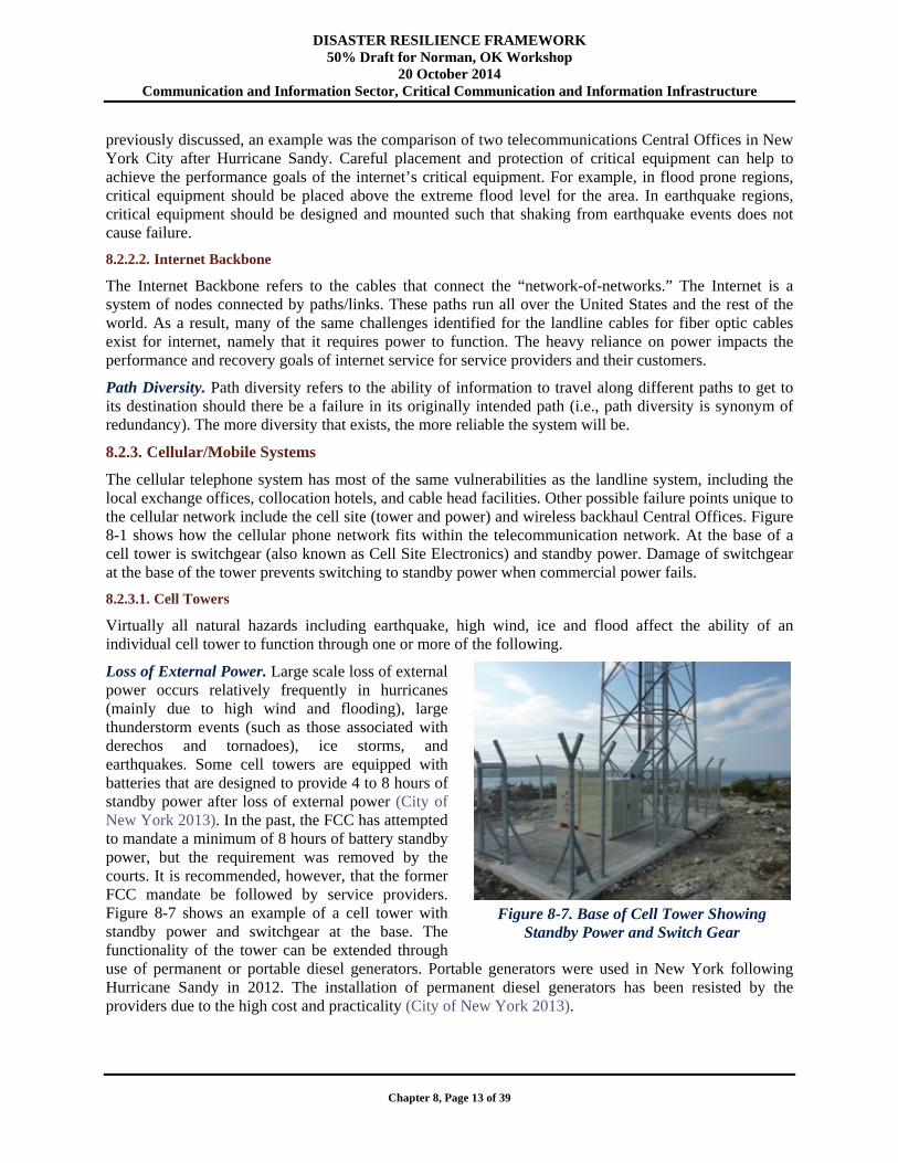
Loss of External Power. Large scale loss of external power occurs relatively frequently in hurricanes (mainly due to high wind and flooding), large thunderstorm events (such as those associated with derechos and tornadoes), ice storms, and earthquakes. Some cell towers are equipped with batteries that are designed to provide 4 to 8 hours of standby power after loss of external power (City of New York 2013). In the past, the FCC has attempted to mandate a minimum of 8 hours of battery standby power, but the requirement was removed by the courts. It is recommended, however, that the former FCC mandate be followed by service providers. Figure 8-7 shows an example of a cell tower with standby power and switchgear at the base. The functionality of the tower can be extended through use of permanent or portable diesel generators. Portable generators were used in New York following Hurricane Sandy in 2012. The installation of permanent diesel generators has been resisted by the providers due to the high cost and practicality (City of New York 2013).
Figure 8-7. Base of Cell Tower Showing
Standby Power and Switch Gear
DISASTER RESILIENCE FRAMEWORK 50% Draft for Norman, OK Workshop
20 October 2014 Communication and Information Sector, Critical Communication and Information Infrastructure
Chapter 8, Page 14 of 39
Recalling that buildings and systems should remain fully functional during and after a routine event (Chapter 3), all cellular towers and attached equipment should remain operational. There is an expectation that the 9-1-1 emergency call system will remain functional during and after the event. Considering the poor performance of the electric grid experienced during recent hurricanes (which produced wind speeds less than the nominal 50 to 100-year values as specified in ASCE 7 [93, 95, 02 and 05]), external power is unlikely to remain functional during the expected, or even routine (as defined in Chapter 2) event. Consequently, adequate standby power is critical to ensure functionality. Recent experience with hurricanes and other disaster events suggest that the standby power needs to last longer than the typical current practice of four to eight hours (City of New York 2013).
In flood prone areas, the standby power needs to located, at a minimum, above the 100-year flood level to ensure functionality after the event. Similarly, the equipment must be resistant to the 50-year earthquake load.
The use of permanently located diesel electric standby power poses significant difficulties due to the initial and ongoing required maintenance costs. Diesel generators are often (though not always) loud and may generate complaints from nearby residents. In the case of events, such as hurricanes and major ice storms, where advanced warning is available, portable generators can be staged and deployed after the storm. However, for widespread disasters, such as hurricanes and ice storms, the need often exceeds the ability to deploy all of the portable generators needed. When they are deployed, the portable generators usually require refueling about once per day so continued access is important. Permanent generators also require refueling, but the frequency is variable due to the different capacities of permanent generators. In events where there is little to no warning, such as earthquakes and tornadoes, staging of portable generators cannot be completed ahead of time.
In highly urbanized areas, such as New York City, cell towers are frequently located on top of buildings, preventing the placement of permanent diesel standby generators and making it difficult to supply power from portable generators because of impeded access.
Improvements in battery technology and the use of hydrogen fuel cell technologies may alleviate some of the standby power issues. Furthermore, newer cellular phone technologies require less power, potentially leading to longer battery life. Standby battery technology is a key consideration in establishing the performance goals of cellular phones in the wake of a disaster event.
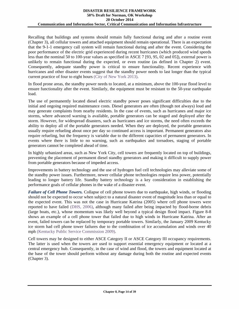
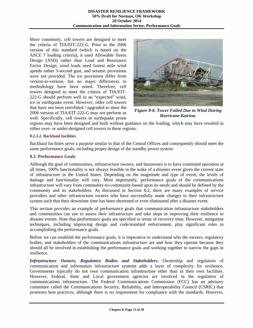
Failure of Cell Phone Towers. Collapse of cell phone towers due to earthquake, high winds, or flooding should not be expected to occur when subject to a natural disaster event of magnitude less than or equal to the expected event. This was not the case in Hurricane Katrina (2005) where cell phone towers were reported to have failed (DHS, 2006), although many failed after being impacted by flood-borne debris (large boats, etc.), whose momentum was likely well beyond a typical design flood impact. Figure 8-8 shows an example of a cell phone tower that failed due to high winds in Hurricane Katrina. After an event, failed towers can be replaced by temporary portable towers. Similarly, the January 2009 Kentucky ice storm had cell phone tower failures due to the combination of ice accumulation and winds over 40 mph (Kentucky Public Service Commission 2009).
Cell towers may be designed to either ASCE Category II or ASCE Category III occupancy requirements. The latter is used when the towers are used to support essential emergency equipment or located at a central emergency hub. Consequently, in the case of wind and flood, the towers and equipment located at the base of the tower should perform without any damage during both the routine and expected events (Chapter 3).
DISASTER RESILIENCE FRAMEWORK 50% Draft for Norman, OK Workshop
20 October 2014 Communication and Information Sector, Performance Goals
Chapter 8, Page 15 of 39
More commonly, cell towers are designed to meet the criteria of TIA/EIT-222-G. Prior to the 2006 version of this standard (which is based on the ASCE 7 loading criteria), it used Allowable Stress Design (ASD) rather than Load and Resistance Factor Design, wind loads used fastest mile wind speeds rather 3-second gust, and seismic provisions were not provided. The ice provisions differ from version-to-version, but no major differences in methodology have been noted. Therefore, cell towers designed to meet the criteria of TIA/EIT-222-G should perform well in an “expected” wind, ice or earthquake event. However, older cell towers that have not been retrofitted / upgraded to meet the 2006 version of TIA/EIT-222-G may not perform as well. Specifically, cell towers in earthquake prone regions may have been designed and built without guidance on the loading, which may have resulted in either over- or under-designed cell towers in these regions.
8.2.3.2. Backhaul facilities
Backhaul facilities serve a purpose similar to that of the Central Offices and consequently should meet the same performance goals, including proper design of the standby power system.
8.3. Performance Goals
Although the goal of communities, infrastructure owners, and businesses is to have continued operation at all times, 100% functionality is not always feasible in the wake of a disaster event given the current state of infrastructure in the United States. Depending on the magnitude and type of event, the levels of damage and functionality will vary. Most importantly, performance goals of the communications infrastructure will vary from community-to-community based upon its needs and should be defined by the community and its stakeholders. As discussed in Section 8.2, there are many examples of service providers and other infrastructure owners who have successfully made changes to their infrastructure system such that their downtime time has been shortened or even eliminated after a disaster event.
This section provides an example of performance goals that communication infrastructure stakeholders and communities can use to assess their infrastructure and take steps in improving their resilience to disaster events. Note that performance goals are specified in terms of recovery time. However, mitigation techniques, including improving design and code/standard enforcement, play significant roles in accomplishing the performance goals.
Before we can establish the performance goals, it is imperative to understand who the owners, regulatory bodies, and stakeholders of the communications infrastructure are and how they operate because they should all be involved in establishing the performance goals and working together to narrow the gaps in resilience.
Infrastructure Owners, Regulatory Bodies and Stakeholders. Ownership and regulation of communication and information infrastructure systems adds a layer of complexity for resilience. Governments typically do not own communication infrastructure other than in their own facilities. However, Federal, State and Local government agencies are involved in the regulation of communications infrastructure. The Federal Communications Commission (FCC) has an advisory committee called the Communications Security, Reliability, and Interoperability Council (CSRIC) that promotes best practices, although there is no requirement for compliance with the standards. However,
Figure 8-8. Tower Failed Due to Wind During
Hurricane Katrina.

DISASTER RESILIENCE FRAMEWORK 50% Draft for Norman, OK Workshop
20 October 2014 Communication and Information Sector, Performance Goals
Chapter 8, Page 16 of 39
best practices are often implemented by service providers (despite not being standards) because they help mitigate risks, which is a good idea in a competitive industry. The FCC has authority over wireless, long-distance telephone, and internet services, whereas state agencies have authority over local landlines and agencies at all levels have regulatory authority over cable (City of New York 2013). Within these three levels of government, there may be multiple agencies involved in overseeing infrastructure. State and local Departments of Transportation (DOTs) control access to roadway rights-of-way for construction. The local Department of Buildings (DOB) regulates the placement of electrical equipment, standby power, and fuel storage at critical telecommunications facilities as specified in their local Building Codes (City of New York 2013).
Service providers own communications infrastructure. The Telecommunications Act of 1996 was established to promote competition in the communications industry (FCC 2011), which would result in lower prices for customers. This has resulted in a growing number of industry players who share infrastructure to offer options for their services to customers more efficiently. Service providers can sometimes share infrastructure to provide their services. However, their infrastructure cannot always be shared because different providers use different technology that is not compatible.
Telecommunication and Cable/Internet Service Providers, such as AT&T and Verizon, often share infrastructure with providers in the energy industry. For example, utility poles for overhead wires typically serve to transport electric energy, telecommunications and cable. It is, therefore, essential that key members from these service providers are involved in establishing, or agreeing to, the performance goals for the communications infrastructure. Improved performance of their infrastructure, much like the power industry, will result in improved service in the wake of a disaster event. Moreover, improvements made to achieve the performance goals may result in better performance on a day-to-day basis as well. A service provider may benefit from excellent performance following a disaster event because customers frustrated with their own service may look for other options that are more reliable. However, this may not always be true because some service providers share infrastructure and thus, failures may occur due to interdependencies. Moreover, in a competitive cost-driven industry, the cost to make a system more resilient (which is passed down to the customers) may result in losing business. Therefore, including service providers in the group of stakeholders is key because their industry is quite complex.
After the AT&T divestiture of 1984, the end-user became responsible for the voice and data cabling on its premises (Anixter Inc. 2013). Therefore, building owners are responsible for communications infrastructure within their facilities. As a result, standards have been developed by the American National Standards Institute/Telecommunications Industry Association (ANSI/TIA) for different types of premises, including:
Commercial buildings (e.g., office and university campus buildings) Residential buildings (e.g., single and multi-unit homes) Industrial buildings (e.g., factories and testing laboratories) Healthcare facilities (e.g., hospitals)
Communications infrastructure has owners and stakeholders from multiple industries that must be included in establishing the performance goals and improving resilience of the components of the system. For resilience of the transmission and distribution communication systems, service provider representatives, including designer professionals (engineers and architects for buildings owned by service providers such as Central Offices/data centers), planners, utility operators, and financial decision makers (i.e., financial analysts) for power service providers must be included in the process. Owners of buildings that are leased by service providers to house critical equipment and nodes in their system are important stakeholders. Additionally, representatives of end-users from different industries should be included to establish the performance goals and improve the resilience of the transfer of the communications system from the provider to the building owner. Specifically, transfer of telecommunications and internet to a

DISASTER RESILIENCE FRAMEWORK 50% Draft for Norman, OK Workshop
20 October 2014 Communication and Information Sector, Performance Goals
Chapter 8, Page 17 of 39
building is often through a single-point of failure. Hence, those involved in building design, such as planners, architects, engineers, and owners need to be aware of potential opportunities to increase redundancy and resiliency.
Performance Goals. Performance goals in this document are defined in terms of how quickly the functionality of the infrastructure can be recovered after a disaster event. Minimizing downtime can be achieved during the design process. A generic table of performance goals for communications infrastructure, similar to the format presented in the Oregon Resilience Plan (OSSPAC 2013), is presented in Table 8-1. The Table 8-1 performance goals are recommendations for a generic “expected” event. However, it is noted that these performance goals were developed based on an expected wind event using current ASCE (ASCE 7-10) design criteria and performance seen in past high wind events. Thus, these goals can be adjusted by users as necessary for their community to meet its social needs, consider their state of infrastructure, and the type and magnitude of hazard. For example, an earthquake prone region may have different performance goals because the design philosophy is for life safety as opposed to wind design which focuses on serviceability.
Table 8-1 is intended as a guide that communities/owners can use to evaluate their strengths and weaknesses in terms of the resilience of their communications systems infrastructure. It is recommended that communities and stakeholders use the table as a tool to assess what their performance goals should be based on their local social needs. Tables similar to that of Table 8-1 can be developed for any community (urban or rural), any type of disaster event, and for the various levels of hazards (routine, expected and extreme) defined in Chapter 3 of the framework.
Table 8-1 presents an example of suggested performance goals for different components of the communications infrastructure when subjected to an expected event. The orange shaded boxes indicate the desired time to have 30% functionality of the component. Yellow indicates the time frame in which 60% operability is desired and green indicates greater than 90% operability. We do not set a goal specifically for 100% operability in this example because it may take significantly longer to reach this target and may not be necessary for communities to return to their normal daily lives. The performance of many of the components in the communication network, such as towers and buildings housing equipment are expected to perform according to their design criteria. Recent history; however, suggests that this is frequently not the case.
In terms of granularity of the performance goals table, the communications infrastructure system is broken down into three categories (see Table 8-1): 1) Nodes/Exchanges/Switching Points, 2) Towers, and 3) Distribution to end users. Although the different components of the system (e.g., underground cables, overhead cables, etc.) are not specifically included in the performance goals, they must be considered to achieve the performance goals specified by the community.
The affected area of a given disaster can also be specified, which is often dependent on the type of hazard. For example earthquake and hurricanes typically have large affected areas, whereas tornadoes and tsunamis have relatively small affected areas. The affected area is important for a community to consider because it will impact how much of the infrastructure may be damaged, which in turn will impact the duration of the recovery process.
DISASTER RESILIENCE FRAMEWORK 50% Draft for Norman, OK Workshop
20 October 2014 Communication and Information Sector, Performance Goals
Chapter 8, Page 18 of 39
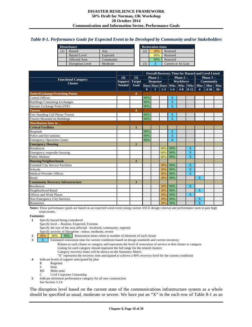
Table 8-1. Performance Goals for Expected Event to be Developed by Community and/or Stakeholders
Disturbance Restoration times (1) Hazard Any (2) 30% Restored
Hazard Level Expected 60% RestoredAffected Area Community 90% RestoredDisruption Level Moderate (3) X Current or At Goal
Functional Category: Cluster
(4) Support Needed
(5) Target Goal
Overall Recovery Time for Hazard and Level Listed Phase 1 -- Response
Phase 2 -- Workforce
Phase 3 -- Community
Days 0
Days1
Days1-3
Wks1-4
Wks 4-8
Wks 8-12
Mos 4
Mos4-36
Mos36+
Nodes/Exchange/Switching Points A Central Offices 90% X Buildings Containing Exchanges 90% X Internet Exchange Point (IXP) 90% X Towers A Free Standing Cell Phone Towers 90% X Towers Mounted on Buildings 90% X Distribution lines to … Critical Facilities 1 Hospitals 90% X Police and fire stations 90% X Emergency Operation Center 90% X Emergency Housing 1 Residences 60% 90% X Emergency responder housing 60% 90% X Public Shelters 60% 90% X Housing/Neighborhoods 2 Essential City Service Facilities 30% 90% X Schools 30% 90% X Medical Provider Offices 30% 90% X Retail 30% 90% X Community Recovery Infrastructure 3 Residences 30% 90% X Neighborhood Retail 30% 90% X Offices and Work Places 30% 90% X Non-Emergency City Services 30% 90% X Businesses 30% 90% X
Notes: These performance goals are based on an expected wind event (using current ASCE design criteria) and performance seen in past high wind events.
Footnotes: 1 Specify hazard being considered
Specify level -- Routine, Expected, Extreme Specify the size of the area affected - localized, community, regional Specify severity of disruption - minor, moderate, severe
2 30% 60% 90% Restoration times relate to number of elements of each cluster 3 X Estimated restoration time for current conditions based on design standards and current inventory
Relates to each cluster or category and represents the level of restoration of service to that cluster or category Listing for each category should represent the full range for the related clusters Category recovery times will be shown on the Summary Matrix "X" represents the recovery time anticipated to achieve a 90% recovery level for the current conditions
4 Indicate levels of support anticipated by plan R Regional S State MS Multi-state C Civil Corporate Citizenship
5 Indicate minimum performance category for all new construction. See Section 3.2.6
The disruption level based on the current state of the communications infrastructure system as a whole should be specified as usual, moderate or severe. We have put an “X” in the each row of Table 8-1 as an
DISASTER RESILIENCE FRAMEWORK 50% Draft for Norman, OK Workshop
20 October 2014 Communication and Information Sector, Regulatory Environment
Chapter 8, Page 19 of 39
example of how a community can indicate the expected performance and recovery of the infrastructure in their evaluation. As seen in Table 8-1, the “X” indicates that there is a significant gap between what is desired and what reality is for all of the components. This is a resilience gap. If the community decides that improving the resilience of their Central Offices, for example, is a top priority after its evaluation of their infrastructure, the next step would be to determine how to reduce this resilience gap. For Central Offices and their equipment, there are a number of solutions that can help to narrow the gap in resilience, including hardening the building to resist extreme loads and protecting equipment hazards such as flooding by elevating electrical equipment and emergency equipment above extreme flooding levels. These lessons have been learned through past disasters, including the 9-11 terrorist attacks, Hurricane Sandy, Hurricane Katrina, and others.
As previously discussed, the performance goals may vary from community-to-community based upon its social needs. It is recommended that representatives of the stakeholders in a given community participate in establishing the performance goals and evaluating the current state of the systems. As discussed throughout the framework, contributions to community resilience include those from design professionals (e.g., engineers and architects), planners, utility operators, regulatory agencies, emergency management planners and first responders, business and political leaders, communications providers, financial analysts, building owners, etc. The City of San Francisco provides an excellent example of what bringing together stakeholders can accomplish. San Francisco has developed a lifelines council (The Lifelines Council of the City and County of San Francisco 2014), which brings together different stakeholders to get input regarding the current state of infrastructure and how improvements can be made in practice. The lifelines council performs studies and provides recommendations as to where enhancements in infrastructure resilience and coordination are needed (The Lifelines Council of the City and County of San Francisco 2014). Their work has led to additional redundancy being implemented into the system in the Bay Area.
8.4. Regulatory Environment
There are multiple regulatory bodies at the various levels of government (Federal, State, and Local) that have authority over communications infrastructure. There is no one regulatory body that oversees all communication infrastructure and is responsible for enforcement of the various standards and codes. Furthermore, the rapidly evolving technologies over the past 30 years have led to changes in regulatory jurisdiction, which adds complexity to the regulatory environment. This section discusses regulatory bodies of communications infrastructure at the Federal, State, and Local levels.
8.4.1. Federal
The regulatory body of communication services and, thus, infrastructure is the FCC. The FCC is a government agency that regulates interstate and international communications of telephone, cable, radio and other forms of communication. Therefore, it has jurisdiction over wireless, long-distance telephone, and the Internet (including VoIP).
As discussed earlier in this chapter, the FCC has an advisory group called the Communications Security, Reliability, and Interoperability Council (CSRIC) that promotes best practices. The council performs studies, including after disaster events, such as Hurricane Katrina, and recommends ways to improve disaster preparedness, network reliability, and communications among first responders (Victory et. al 2006). The recommended best practices are not required to be adopted and enforced since they are not standards. However, as was learned in the stakeholder workshops held to inform this framework, industry considers best practices voluntary good things to do. Furthermore, implementing best practices allows service providers to remain competitive in terms of business.
DISASTER RESILIENCE FRAMEWORK 50% Draft for Norman, OK Workshop
20 October 2014 Communication and Information Sector, Standards and Codes
Chapter 8, Page 20 of 39
8.4.2. State
State government agencies have authority over local landline telephone service. Most commonly, the agency responsible for overseeing communications infrastructure at the State level is known as the Public Service Commission (PSC). However, other State agencies have jurisdiction over telecommunications infrastructure as well. A prime example is the State DOT. The State DOT has jurisdiction over the right-of-way and, therefore, oversees construction of roads/highways where utility poles and wires are built. Utility poles and wires are commonly placed within the right-of-way of roads, whether it is above ground or underground. The DOT has the ability to permit or deny planned paths of the utilities.
8.4.3. Local
Local government has jurisdiction over communication infrastructure through a number of agencies. The Department of Buildings (DOB), or equivalent, is responsible for enforcing the local Building Code. Therefore, the DOB regulates the placement of electrical equipment, standby power, and fuel storage at critical telecommunications facilities such as Central Offices (City of New York 2013).
Large cities, such as New York City, Chicago, Los Angeles, and Seattle have their own DOT (City of New York 2013). These local DOTs oversee road construction and the associated right-of-way for utilities (including communications infrastructure). Many smaller municipalities have an Office of Transportation Planning, which serves a similar function.
8.4.4. Overlapping Jurisdiction
Due to the complex bundling packages that service providers now offer customers, a number of regulatory bodies have jurisdiction over the various services provided in said bundle. For example, a bundled telephone, Internet and cable package functions under the jurisdiction of both Local (cable) and Federal (Internet and VoIP) agencies (City of New York 2013). Furthermore, changing from traditional landlines to VoIP shifts a customer’s services from being regulated by State agencies to Federal agencies. As technology continues to evolve, jurisdiction over services may continue to shift from one level of government to another. Following the current trend of more and more services becoming Internet based, the shift of services may continue to move toward being under Federal agency regulations.
8.5. Standards and Codes
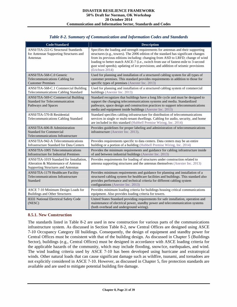
Codes and Standards are used by the communication and information industry to establish the minimum acceptable criteria for design and construction. The codes and standards shown in Table 8-2 were mainly developed by the American National Standards Institute/Telecommunications Industry Association (ANSI/TIA). This organization has developed many standards that are adopted at the state and local government levels as well as by individual organizations. In fact, many of the standards presented in Table 8-2 are referenced and adopted by universities, such as East Tennessee State University (ETSU 2014), in their communication and information systems design guidelines. Individual end-users, such as a university campus or hospital, and levels of government may have additional standards/guidelines.
DISASTER RESILIENCE FRAMEWORK 50% Draft for Norman, OK Workshop
20 October 2014 Communication and Information Sector, Standards and Codes
Chapter 8, Page 21 of 39
Table 8-2. Summary of Communication and Information Codes and Standards
Code/Standard Description
ANSI/TIA-222-G Structural Standards for Antennae Supporting Structures and Antennas
Specifies the loading and strength requirements for antennas and their supporting structures (e.g., towers). The 2006 edition of the standard has significant changes from its previous editions including: changing from ASD to LRFD; change of wind loading to better match ASCE-7 (i.e., switch from use of fastest-mile to 3-second gust wind speeds); updating of ice provisions; and addition of seismic provisions (Erichsen 2014)
ANSI/TIA-568-C.0 Generic Telecommunications Cabling for Customer Premises
Used for planning and installation of a structured cabling system for all types of customer premises. This standard provides requirements in addition to those for specific types of premises (Anexter Inc. 2013)
ANSI/TIA-568-C.1 Commercial Building Telecommunications Cabling Standard
Used for planning and installation of a structured cabling system of commercial buildings (Anexter Inc. 2013)
ANSI/TIA-569-C Commercial Building Standard for Telecommunication Pathways and Spaces
Standard recognizes that buildings have a long life cycle and must be designed to support the changing telecommunications systems and media. Standardized pathways, space design and construction practices to support telecommunications media and equipment inside buildings (Anexter Inc. 2013)
ANSI/TIA-570-B Residential Telecommunications Cabling Standard
Standard specifies cabling infrastructure for distribution of telecommunications services in single or multi-tenant dwellings. Cabling for audio, security, and home are included in this standard (Hubbell Premise Wiring, Inc. 2014)
ANSI/TIA-606-B Administration Standard for Commercial Telecommunications Infrastructure
Provides guidelines for proper labeling and administration of telecommunications infrastructure (Anexter Inc. 2013).
ANSI/TIA-942-A Telecommunications Infrastructure Standard for Data Centers
Provides requirements specific to data centers. Data centers may be an entire building or a portion of a building (Hubbell Premise Wiring, Inc. 2014)
ANSI/TIA-1005 Telecommunications Infrastructure for Industrial Premises
Provides the minimum requirements and guidance for cabling infrastructure inside of and between industrial buildings (Anexter Inc. 2013)
ANSI/TIA-1019 Standard for Installation, Alteration & Maintenance of Antenna Supporting Structures and Antennas
Provides requirements for loading of structures under construction related to antenna supporting structures and the antennas themselves (Anexter Inc. 2013)
ANSI/TIA-1179 Healthcare Facility Telecommunications Infrastructure Standard
Provides minimum requirements and guidance for planning and installation of a structured cabling system for healthcare facilities and buildings. This standard also provides performance and technical criteria for different cabling system configurations (Anexter Inc. 2013)
ASCE 7-10 Minimum Design Loads for Buildings and Other Structures
Provides minimum loading criteria for buildings housing critical communications equipment. Also provides loading criteria for towers.
IEEE National Electrical Safety Code (NESC)
United States Standard providing requirements for safe installation, operation and maintenance of electrical power, standby power and telecommunication systems (both overhead and underground wiring).
8.5.1. New Construction
The standards listed in Table 8-2 are used in new construction for various parts of the communications infrastructure system. As discussed in Section Table 8-2, new Central Offices are designed using ASCE 7-10 Occupancy Category III buildings. Consequently, the design of equipment and standby power for Central Offices must be consistent with that of the building design. As discussed in Chapter 5 (Buildings Sector), buildings (e.g., Central Offices) must be designed in accordance with ASCE loading criteria for the applicable hazards of the community, which may include flooding, snow/ice, earthquakes, and wind. The wind loading criteria used by ASCE 7-10 has been developed using hurricane and extratropical winds. Other natural loads that can cause significant damage such as wildfire, tsunami, and tornadoes are not explicitly considered in ASCE 7-10. However, as discussed in Chapter 5, fire protection standards are available and are used to mitigate potential building fire damage.

DISASTER RESILIENCE FRAMEWORK 50% Draft for Norman, OK Workshop
20 October 2014 Communication and Information Sector, Standards and Codes
Chapter 8, Page 22 of 39
The ANSI/TIA-222-G standard is used for the design of new cell towers. This version of the standards, released in 2006, has included the biggest set of changes since the standard’s inception (TIA 2014). Some of the major changes include:
1. Using limits states design rather than allowable stress design. 2. Changing the design wind speeds from fastest-mile to 3-second gust as is done for ASCE 7 and using
the wind maps from ASCE 7. 3. Earthquake loading is addressed for the first time in the ANSI/TIA-222 standard (Wahba 2003).
Note that wind and ice loading are the predominant concerns for towers. However, earthquake loading was added so that it would be considered in highly seismic regions (Wahba 2003).
8.5.1.1. Implied or Stated Performance Levels for Expected Hazard Levels
As discussed in Chapter 5, the performance level for an expected disaster event depends on the type of hazard and the design philosophy used for said hazard.
For wind, the buildings and other structures are designed for serviceability. That is, in the expected wind event, such as a hurricane, the expectation is that the structure of the building will not fail nor will the building envelope. The ability of the building envelope to perform well (i.e., stay intact) is imperative for high wind events, because they are typically associated with heavy rainfall events (e.g., thunderstorms, hurricanes, tornadoes). Therefore, even if the building frame were to perform well, but the envelope failed, rain infiltration could damage the contents, critical equipment, and induce enough water related damage such that the building would have to be replaced anyway. The expectation is that a Central Office would not have any significant damage for the expected wind event, and would be fully operational within 24 hours. The 24 hours of downtime should only be required for a high wind event to allow for time to bring standby generators online if needed and ensure that all switches and critical electrical equipment are not damaged.
Similarly, for an expected flood, a Central Office should not fail. There is likely to be some damage to the building and its contents at lower elevations, particularly the basement. However, if the critical electrical and switchgear equipment and standby power are located well above the inundation levels, the Central Office would be expected to be fully operational within 24 hours of the event.
For earthquakes, buildings are designed for life safety. Therefore, for Central Offices in highly seismic regions, some damage to the building is likely for the expected earthquake. As a result, it is likely that there will be some loss of functionality of a Central Office following the expected earthquake event. If the critical equipment and switchgear were designed and mounted, the downtime would be expected to be limited (less than one week). However, if the critical equipment and switchgear were not mounted to resist ground accelerations, then it could be weeks before the Central Office is fully functional again.
For cell towers, the primary hazard that is considered for design in ANSI/TIA-222 is wind. However, ice and earthquake are also considered. ANSI/TIA-222 provides three classes of tower structures (Wahba 2003):
Category I Structures: Used for structures where a delay in recovering services would be acceptable. Ice and earthquake are not considered for these structures, and wind speeds for a 25-year return period using the ASCE 7-02/7-05 methodology are used.
Category II Structures: This is the standard category that represents hazard to human life and property if failure occurs. The nominal 50-year return period wind, ice and seismic loads are used.
Category III Structures: Used for critical and emergency services. The nominal 100-year return period loads.
DISASTER RESILIENCE FRAMEWORK 50% Draft for Norman, OK Workshop
20 October 2014 Communication and Information Sector, Standards and Codes
Chapter 8, Page 23 of 39
For the expected event, failures would only be anticipated for a small percentage of cell towers (e.g., less than 5 percent). It is noted that, as discussed in the previous section, the loading in ANSI/TIA-222-G is based on that of ASCE 7.
8.5.1.2. Recovery Levels
As discussed in the previous section, Central Offices and cell towers should not have an extended recovery time for the expected event. Given that the earthquake design philosophy is life safety (rather than wind which is designed for serviceability), Central Offices may have some loss of functionality due to damage to the building envelope and critical equipment if it is not designed and mounted to resist adequate ground accelerations.
With respect to cell towers, wind is the predominant hazard of concern for designers. Ice and earthquake are also considered, though not to the same extent in design. Given that the ANSI/TIA-222-G loads are based on ASCE 7 loading, it is anticipated that only a small percentage of cell towers would fail during an expected event.
For distribution lines, a key factor, more so than the standards, is the location of the cables. For example, if the distribution lines are underground for a high wind or ice event, failures and recovery time should be limited. However, even if the distribution lines are underground it is possible for failure to occur due to uprooting of trees. For flooding, if the distribution lines are not properly protected or there has been degradation of the cable material, failures could occur. For earthquake, failures of underground distribution lines could also occur due to liquefaction. As discussed in Section 8.2.1, although underground lines may be less susceptible to damage, they are more difficult to access to repair and failures could result in recovery times of weeks rather than days. However, for an expected event, limited damage to the distribution lines would be expected.
If the distribution lines are overhead, high wind and ice events will result in failures, largely due to tree fall or other debris impacts on the lines. The debris impacts on distribution lines is a factor that varies locally due to the surroundings and tree trimming programs that are intended to limit these disruptions. Although these lines are more likely to fail due to their direct exposure to high winds and ice, recovery/repair time of the lines for an expected event would be expected to range from a few days to a few weeks depending on the size of the area impacted, resources available, and accessibility to the distribution lines via transportation routes. It is noted that this only accounts for repair of the communications distribution lines itself. Another major consideration is the recovery of external power lines so that the end user is able to use their communications devices. Chapter 7 addresses the standards and codes, and their implied performance levels for an expected event.
8.5.2. Existing Construction
Although the standards listed in 8.2 are used for new construction for communications infrastructure, older versions of these codes and standards were used in the design of structures for the existing infrastructure.
Central Offices designed and constructed within the past 20 years may have been designed to the criteria ASCE 7-88 through 05. Prior to that, ANSI standards were used. There have been many changes in the design loading criteria and methodology over the design life of existing Central Offices. For example, ASCE 7-95 was the first time a 3-second gust was used for the reference wind speed rather than the fastest mile for the wind loading criteria (Mehta 2010). Over the years, reference wind speeds (from the wind speed contour maps) have changed, pressure coefficients have been adjusted, earthquake design spectra, ground accelerations and other requirements have changed. Overall, codes and standards have been added to/changed based on lessons learned from past disaster events and the resulting research findings.
DISASTER RESILIENCE FRAMEWORK 50% Draft for Norman, OK Workshop
20 October 2014 Communication and Information Sector, Standards and Codes
Chapter 8, Page 24 of 39
As discussed in Section 8.5.1, ANSI/TIA-222-G is the current version of the standard used for cell towers and antennas. However, prior to 2006, versions of the code include (TIA 2014):
ANSI/TIA/EIA-222-F established in 1996 ANSI/TIA/EIA-222-E established in 1991 ANSI/TIA/EIA-222-D established in 1987 ANSI/TIA/EIA-222-C established in 1976 ANSI/TIA/EIA-222-B established in 1972 ANSI/TIA/EIA-222-A established in 1966 ANSI/EIA-RS-222 established as the first standard for antenna supporting structures in 1959.
The 1996 standard, ANSI/TIA/EIA-222-F was used during the largest United States growth and construction of towers (TIA 2014). As noted in Section 8.5.1, earthquake was not considered in this version of the standard, allowable stress design was used rather than limit states design, and reference wind speeds used fastest mile rather than 3-second gust (Wahba 2003). It is noted that the use of fastest mile for the reference wind speed is consistent with ASCE 7 prior to the 1995 version (of ASCE).
8.5.2.1. Implied or Stated Performance Levels for Expected Hazard Levels
For existing Central Offices designed to an older version of ASCE 7 or ANSI criteria, these should have similar performance to those of new construction for an expected event. However, it is possible that these structures may have varied performance depending on the design code’s loading criteria. Nonetheless, an existing Central Office should have similar performance to that of a newly constructed Central Office (see Section 8.5.1.1.
As discussed in the previous section, the ANSI/TIA/EIA-222-F 1996 standard was in effect when the largest growth and construction of cell towers took place (TIA 2014). For wind and ice, the towers would be expected to only have a small percentage of failures for the expected event as discussed in Section 8.5.1.1. However, earthquake loading was not included in any of the standards prior to ANSI/TIA-222-G (Wahba 2003). Although earthquake does not typically govern the design of cell towers, highly seismic regions would be susceptible to failures if an expected earthquake occurred. For existing towers designed to standards other than ANSI/TIA-222-G in highly seismic regions, the design should be checked to see if earthquake loads govern and retrofits should be implemented if necessary. It is noted that despite no earthquake loading criteria in ANSI/TIA/EIA-222-F, and older versions of this standard, designers in highly seismic regions may have considered earthquake loading using another standards, such as ASCE 7. However, this was not a requirement.
8.5.2.2. Recovery Levels
As discussed in the previous section and Section 8.5.1.2, Central Offices and cell towers should not require a long time for full recovery after an expected event. However, given that older standards of ANSI/TIA/EIA-222 did not include earthquake loading criteria, a large number of failures and, hence, significant recovery time may be needed to repair or replace towers after an expected event in a highly seismic region. To replace a large number of towers would take weeks, months, or even years depending on the size of the impacted area. As discussed in Section 8.6.4, service providers have the ability to provide cell on light trucks (COLTs) so that essential wireless communications can be brought online quickly after a disaster event in which the network experiences significant disruptions (AT&T 2014). However, the COLTs are only intended for an emergency situation. They are not intended to provide a permanent solution. The best approach for cell tower owners in these earthquake prone regions is, therefore, to ensure that the cell towers can resist the earthquake loading criteria in the new ANSI/TIA standard.
DISASTER RESILIENCE FRAMEWORK 50% Draft for Norman, OK Workshop
20 October 2014 Communication and Information Sector, Resilience Assessment Methodology
Chapter 8, Page 25 of 39
With respect to performance of distribution lines, the performance and recovery time is largely dependent on the placement of the cables (i.e., overhead versus underground) as discussed in 8.5.1.2.
8.6. Resilience Assessment Methodology
Section 8.2 discusses critical components of communication and information infrastructure. The discussion includes examples from different types of hazards to encourage the reader to think about the different hazards that could impact the communication and information infrastructure in their community. The number, types, and magnitudes of hazards that need to be considered will vary from community to community.
Section 8.3 discusses the performance goals of the communication and information infrastructure strived for by the community. Section 8.3 does provide recommended performance goals for the routine, expected and extreme event. However, the performance goals should be adjusted by the community based on its social needs, which will vary by community.
Section 8.4 and 8.5 outline some of the regulatory levels and issues, and codes and standards that the reader should keep in mind when planning to make upgrades/changes to existing structures as well as building new structures for their communications network. The objective of this section is use the information from Section 8.2 through 8.5 to provide guidance on how a community should work through the process of assessing their communications infrastructure, defining strategies to make its infrastructure more resilient, and narrowing the resilience gaps.
8.6.1. Assessment Methodology
Recall that in the Section 8.2 discussion of setting performance goals of the communication and information infrastructure, there was also an “X” in each row corresponding to an example of what a community actually found its infrastructures’ performance to be given a level of hazard. The question for the community then becomes: How do we (the community) determine where the “X” belongs for the various types of infrastructure in our community?
At this point, the community should have convened a collection (or panel) of stakeholders and decision makers to approach the problem and establish the performance goals for each type and magnitude of hazard. To assess the infrastructure, this panel should have the knowledge or reach out to those in the community who have the knowledge to assess the state of the infrastructure. The panel of stakeholders and decision makers will have to assess the infrastructures’ performance relative to the type and magnitude of event that the community may face because different types of hazards will result in different types of failure modes and, consequently, performance. In some communities, it may only be necessary to make assessments for one hazard (such as earthquake in some non-coastal communities in California or Oregon). In other communities, it may be appropriate to complete assessments of the performance for multiple types of hazards such as high winds and storm surge in coastal communities in the Gulf and east coast regions of the United States.
There are three levels at which the infrastructure can be assessed:
Tier 1. A high level assessment of the expected performance of the components of the communications infrastructure can be completed by those with knowledge and experience of how the components and system will behave in a disaster event. For Central Offices, this may include civil and electrical engineer/designers. For wires (both overhead and underground), and cell towers, this may include engineers, utility operators, service providers technical staff, etc. As a minimum, each community should complete a high level (Tier 1) assessment of its infrastructure. The community can then decide whether additional investment is warranted in completing a more detailed assessment. The SPUR Framework (Poland 2009) took this high level approach in assessing their infrastructure for the City of San Francisco, and is highly regarded as a good example for the work completed to date.
DISASTER RESILIENCE FRAMEWORK 50% Draft for Norman, OK Workshop
20 October 2014 Communication and Information Sector, Resilience Assessment Methodology
Chapter 8, Page 26 of 39
Tier 2. A more detailed assessment can be used based on an inventory of typical features within the communication infrastructure system to develop generalized features for various components of the infrastructure. To do this, the community would have to use or develop a model for their community to assess the performance of common components of their infrastructure system for a specific type and magnitude of event (i.e., model a scenario event and its resulting impacts). Alternatively, the community could model a disaster event scenario to compute the loads (wind speeds/pressures, ground accelerations, flood elevations) to be experienced in the community and use expert judgment to understand what the performance of the various components of the communications infrastructure would be as a result of the loading. A Tier 2 communication and information infrastructure assessment would include the impact on typical components of the infrastructure system independent of the intra-dependencies. The Oregon Resilience Plan (OSSPAC 2013) provides a good example of modeling a disaster event to assess the resulting impacts of the current infrastructure. It used HAZUS-MH to model and determine the impacts of a Cascadia earthquake on the different types of infrastructure and used the losses output by the HAZUS tool to back-calculate the current state of the infrastructure.
Tier 3. For the most detailed level of analysis, a Tier 3 assessment would include all components in the communications infrastructure system, intra-dependencies within the system, and inter-dependencies with the infrastructure of other sectors. Fragilities could be developed for each component of the communications infrastructure system. A Tier 3 assessment would use model/tools to determine both the loading of infrastructure due to the hazard and the resulting performance including intra- and inter-dependencies. Currently, there are no publicly available tools that can be used to model the intra- and interdependencies.
8.6.2. Strategies for New/Future Construction
For new and future construction, designers are encouraged to consider the performance goals and how to best achieve those goals rather than designing to the minimum code levels, which are sometimes just for life safety (e.g., earthquake design). It is important to consider the communication and information infrastructure as a whole because it is a network and failure in one part of the system impacts the rest of the system (or at least the system connected directly to it). Therefore, if it is known that a critical component of the infrastructure system is going to be non-redundant (e.g., a lone Central Office, or a single point of entry for telephone wires into a critical facility), then it is recommended that the component be designed to achieve performance goals set for the “extreme” hazard.
Throughout this chapter, there are examples of success stories and failures of communications infrastructure due to different types of hazards (wind, flood, earthquake, ice storms). Designers, planners and decisions makers should think about these examples, as well as other relevant examples, when planning for and constructing new communications and information infrastructure. There are several construction and non-construction strategies that can be used to successfully improve the resilience of communications infrastructure within a community.
Construction Strategies for New/Future Central Offices. With respect to Central Offices that are owned by service providers, the service provider should require the building be designed such that it can withstand the appropriate type and magnitude of disaster event(s) that may occur for the community. It is imperative that all hazards the community may face are addressed because hazards result in different failure modes and so designing for an extreme earthquake may not protect your infrastructure from the expected flood, or vice versa. However, as was discussed during the workshops held to inform this framework, not all central offices or other nodes housing critical communications equipment are owned by service providers.
Sections of buildings are often leased by service providers to store their equipment for exchanges or nodes in the system. In this case, service providers typically have no influence over the design of the building. But, if a building is in the design phase and the service provider is committed to using the space
DISASTER RESILIENCE FRAMEWORK 50% Draft for Norman, OK Workshop
20 October 2014 Communication and Information Sector, Resilience Assessment Methodology
Chapter 8, Page 27 of 39
of the building owner, the service provider could potentially work with the building owner and designers to ensure their section of the building is designed such that their critical equipment is able to withstand the appropriate loading. In a sense, the goal would be to “harden” the section of the building in the design phase rather than retrofitting the section of the structure after a disaster as is often done. Adding the additional protection into the design of the building would likely cost more initially, and the building owner would likely want the service provider to help address the additional cost. However, the service provider would be able to compute a cost-to-benefit ratio of investment for paying for additional protection of their critical equipment versus losing their equipment and having to replace it.
Non-Construction Strategies for New/Future Central Offices. Although the design and construction of buildings that house critical equipment for central offices, exchanges, and other nodes in the communications network is an important consideration, non-construction strategies can also be extremely effective. For example, service providers who own buildings for their Central Offices should place their critical equipment such that it is not vulnerable to the hazards faced by the community. For example, Central Offices vulnerable to flooding should not have critical electrical equipment or standby generators in the basement. Rather, the critical electrical equipment and standby generators should be located well above the extreme flood levels. As was shown by the success story of the Verizon Central Office after Hurricane Sandy described in Section 8.2.1, placing the critical equipment and standby generators above the extreme flood level can reduce the recovery time needed significantly. Similarly, for Central Offices in earthquake prone areas, service providers can mount their critical equipment to ensure it does not fail due to the shaking of earthquakes.
Service providers planning to lease space from another building owner should be aware of the hazards faced by the community and use that information in the decision making process. For instance, a service provider would not want to rent space in the basement of a 20-story building to store electrical and critical equipment for an exchange/node.
Construction Strategies for New/Future Cell Towers. New/Future Cell Towers should be designed to the latest TIA/EIT-222-G standard. As discussed in Section 8.2.3, the 2006 version of the TIA/EIT-222-G standard was updated to reflect the design criteria in ASCE 7 for wind, ice, and earthquake loading. Hence, for wind and ice, if the towers are designed and constructed in accordance with the appropriate standard(s), only a small percentage of cell towers would be anticipated to fail in an “expected” event. With respect to earthquake, where the design philosophy is life safety, towers should be designed beyond the code loading criteria. Since cell towers are becoming more numerous, it is recommended that they be designed to the “expected” event.
Non-Construction Strategies for New/Future Cell Towers. Historically, the predominant cause of outages of cell towers has been the loss of electrical power. As discussed in Section 8.2.3, the FCC has attempted to mandate a minimum of 8 hours of battery standby power to overcome this problem, but the requirement was removed by the courts. However, it is recommended that service providers follow the former FCC mandate.
As is the case for standby generators in Central Offices, standby generators for cell towers must be placed appropriately. Standby generators for cell towers in areas susceptible to flooding should be placed above the “expected” flood level. Similarly, in earthquake regions, standby generators should be mounted such that the ground accelerations do not cause failure on the standby generator.
Additional protection should be implemented for cell towers when appropriate and feasible. As discussed in Section 8.2.3, during Hurricane Katrina debris impacts from boats in flood areas resulted in failure of cell towers. Furthermore, impacts from uprooted trees or branches during high wind events and tsunamis could also result in failure of these towers. Therefore, it is recommended that the topography and surroundings (e.g., relative distance from trees or harbors to cell towers) be taken into consideration to ensure cell towers are protected from debris impact.
DISASTER RESILIENCE FRAMEWORK 50% Draft for Norman, OK Workshop
20 October 2014 Communication and Information Sector, Resilience Assessment Methodology
Chapter 8, Page 28 of 39
Strategies for New/Future Distribution Line to End User. As discussed in Section 8.2.1, there are several different types of wires (copper, coaxial, and fiber optic) that carry services to the end user. Each of the types of wires has advantages and disadvantages (see Section 8.2.1). More and more, service providers are installing fiber optic wires to carry services to the customer.
There is an ongoing debate regarding whether underground or overhead wires are the best way to distribute services to the end user. For new/future distribution lines, several factors should be used to decide which method of distribution of services is best. The factors should include:
1. The building cluster to which the services are being distributed 2. The potential hazards to which the community is susceptible 3. Topography and surroundings of distribution lines 4. Redundancy or path diversity of distribution lines
Items 1-3, as listed, can be considered together. The building cluster to which the services are being delivered (item 1) is a key consideration. As seen in Section 8.3, performance goals for transmission of communications services to critical facilities reflect a desire for less recovery time (i.e., better performance) than the clusters for emergency housing, housing/neighborhoods, and community recovery. The hazards the community faces (item 2) can be used to determine how to best prevent interruption of service distribution to the building (i.e., end user). As an example, in regions that are susceptible to high winds events (i.e., item 2), it may be appropriate to distribute communication services to critical services (and other clusters) using underground wires rather than overhead wires. The use of overhead wires would likely result in poorer performance in wind events because of failures due to wind loading or, more likely, debris (i.e., tree) impact (item 3).
Redundancy or path diversity (item 4) of communications distribution lines to end users is an important consideration. As discussed in Section 8.2.1, building redundancy in the communications network is essential to ensuring the continuation of services after a disaster event. For example, single points of failure in the last/first mile of distribution can be vulnerable to failure resulting in long term outages. It is recommended that redundancy (i.e., path diversity) is built into in the distribution network, especially the last/first mile, wherever possible.
8.6.3. Strategies for Existing Construction
Similar to new/future communication and information infrastructure, there are several construction and non-construction strategies that can be used to successfully improve the resilience of existing communications infrastructure within a community. However, unlike new/future components of the communications infrastructure system, existing components must be evaluated first to understand their vulnerabilities, if they exist. If it is determined that a component is vulnerable to natural loads, then strategies should be used to improve its resilience. Given that the communication and information infrastructure system is extremely large and much of the existing infrastructure is owned by service providers or third party owner (e.g., building owners) with competing needs for funding, it is not reasonable to expect that the capital is available for service providers (or third parties) to upgrade all of their infrastructure immediately. However, prioritization can be used to address the most critical issues early in the process and develop a strategy to address many concerns over a longer time period. Moreover, by evaluating the inventory of existing infrastructure and identifying weaknesses, service providers can use the data to implement strategies for new/future infrastructure construction so the same weaknesses are not repeated.
Construction Strategies for Existing Central Offices. Existing buildings that are owned by service providers and used as Central Offices should be assessed to determine if the building itself and sections of the building containing critical equipment and standby generators will be able to meet the performance goals (see Section 8.3). As stated for the case of new/future construction, if the Central Office is a non-
DISASTER RESILIENCE FRAMEWORK 50% Draft for Norman, OK Workshop
20 October 2014 Communication and Information Sector, Resilience Assessment Methodology
Chapter 8, Page 29 of 39
redundant node in the service provider’s infrastructure network, then the Central Office should be evaluated to ensure it can resist the “extreme” level of hazard. However, if the Central Office is a node in a redundant infrastructure system, and failure of the Central Office would not cause any long-term service interruptions, then Central Office should be assessed to ensure it can withstand the loads for the “expected” event.
If the service provider finds that its Central Office will not be able to withstand the loading for the appropriate level of disaster event as previously described, then the service provider should take steps to harden the building. Although this is likely to be very expensive, if the Central Office is critical to the service provider’s performance following a disaster event in both the short and long term, then a large investment may be necessary and within a reasonable cost-benefit ratio.
For nodes, exchanges, or central offices located in leased (existing) buildings, the service provider does not have control over retrofitting or hardening the building. However, the service provider could attempt to work with the building owner to have the sections of the building housing critical equipment hardened. Alternatively, there are also several non-construction strategies that could be used to protect the critical equipment.
Non-Construction Strategies for Existing Central Offices. The critical equipment in Central Offices or in other nodes/exchanges in the communications infrastructure network should be assessed to determine whether it is likely to fail during the disaster events faced by that community. Whether the building is owned by the service provider or leased from a third party, relatively easy and inexpensive changes can be made to protect the critical equipment.
As was demonstrated by the example of the Manhattan Verizon Central Office discussed in Section 8.2.1, non-construction strategies can be used to successfully improve the performance of the critical equipment in disaster events. Recall that after 9-11, the Manhattan Verizon Central Office was hardened. However, what may have been the most successful change was elevating the standby generators and critical equipment to higher elevations such that they would not fail in the case of flooding (City of New York 2013). Compared to another Central Office located at 104 Broad Street in New York City, which had their critical equipment and standby generators stored in the basement, the Verizon Central Office performed much better. The 104 Broad Street had an outage of 11 days, whereas the Verizon Central Office was operational within 24 hours. In terms of the performance goals shown for the expected event in Section 8.3, the 104 Broad Street did not meet the performance goals. However, with the relatively easy changes made in elevating the critical equipment and standby generators, the Verizon Central Office met the performance goals presented in Section 8.3.
Construction Strategies for Existing Cell Towers. Existing cell towers should be evaluated to determine whether they can resist the loading from the “expected” event that the community faces (wind speed/pressure, earthquake ground accelerations, ice storms). Versions older than the 2006 ANSI/TIA-222-G did not include earthquake design criteria. Therefore, it is recommended that the design loads for existing cell towers, particularly in earthquake prone regions, be assessed to understand the loading that the towers can withstand. It is assumed that a designer in an earthquake prone region would use loading based on other codes and standards, but it is possible that the loading used in the original design may not be adequate. If it is found after assessing the cell tower for earthquake loading that it was not designed to resist adequate loads, then retrofits, such as the addition of vertical bracing, can be constructed to ensure that the loading can be resisted. Similarly, since there have been changes in the wind and ice loading in ANSI/TIA-222-G to better match the loading criteria in ASCE, cell towers should be assessed to ensure they will resist the appropriate loads, and retrofitted if needed.
Non-Construction Strategies for Existing Cell Towers. Existing cell tower sites should be assessed to determine whether adequate standby power (8+ hours) supply is available and whether the standby generator and switchgear are protected against loading from the appropriate magnitude (expected) of
DISASTER RESILIENCE FRAMEWORK 50% Draft for Norman, OK Workshop
20 October 2014 Communication and Information Sector, Resilience Assessment Methodology
Chapter 8, Page 30 of 39
natural hazard. Although it may not be economically feasible to provide standby generators for all cell towers immediately, a program can be developed to accomplish this over a period of time. The immediate surroundings of cell sites should also be assessed to determine vulnerabilities to debris, either airborne or waterborne. If the cell site is located such that it is vulnerable to tree fall or other debris in a high wind or flood event, then it is recommended that additional protection be provided to protect the cell tower.
Strategies for Existing Distribution Line to End User. For existing distribution lines to the end user, an inventory of the wires, including the type, age, and condition of the wires should be recorded. When wires are found damaged or have deteriorated due to their age, they should be retired and/or replaced.
As discussed for new/future distribution lines, overhead v. underground wires is an ongoing debate in the industry. The distribution lines, particularly to critical buildings, should be assessed to determine whether overhead or underground wires are best for the communications infrastructure system. However, if a service provider is considering switching from overhead wires to underground wires to avoid possible outages due to ice storms or high wind events, a cost-benefit ratio should be computed as part of the assessment and decision making process. If the cost is much greater than the projected benefits, the service provider may want to consider other priorities in making their infrastructure more resilient. In fact, rather than switching the distribution lines from overhead to underground wires, the service provider may find it more economical to add redundancy (i.e., path diversity) to that part of the infrastructure network. Thus, the service provider would not be reducing the risk to the existing overhead distribution wires, but reducing the risk of service interruptions because it is not solely reliant on the overhead distribution lines.
8.6.4. Addressing Gaps in Resilience Plans
After the community stakeholders (including service providers) establish performance goals for the communications infrastructure and an assessment of the critical infrastructure is complete, the mitigation strategies discussed in Sections 8.6.2 and 8.6.3 can be used to reduce the resilience gaps. These strategies include:
Designing new/future buildings that house Central Offices and other exchanges/nodes in the communications infrastructure system to resist the loads associated with the appropriate disaster level and performance goals When the service providers own these buildings, they can work directly with building designers
to ensure the building meets appropriate loading criteria to meet performance goals for resilience. When service providers commit to leasing a new/future building from a third party, service
providers can attempt to work with the building owner to ensure the sections of the building they committed to leasing are designed (i.e., hardened) to resist the appropriate loads.
Hardening existing buildings owned by service providers that house Central Offices and other exchanges/nodes in the communications infrastructure system to resist appropriate loads to meet performance goals
Placing and securing critical equipment in Central Offices such that it is not vulnerable to hazards faced by the community, whether flooding, earthquake, etc.
Designing or retrofitting cell towers, as needed, to ensure they resist the loads associated with the “expected” hazard level
Ensuring 8+ hours of standby power is available for cell towers so that they can function for a reasonable period of time in the immediate aftermath of a disaster event
Placing and securing cell tower standby power and switchgear such that they are not impacted by the “expected” event
Ensuring distribution lines have redundancy (path diversity) built into the network Placing distribution lines so that their vulnerability to natural hazards is minimized
DISASTER RESILIENCE FRAMEWORK 50% Draft for Norman, OK Workshop
20 October 2014 Communication and Information Sector, Tools Needed for Resilience
Chapter 8, Page 31 of 39
As can be seen, there are several mitigation strategies that can be used to reduce the resilience gaps of the communication infrastructure system. However, service providers and other stakeholders, such as third party building owners, responsible for infrastructure cannot make all recommended changes in the short term due to limited resources, a competitive environment driven by costs, and competing needs. Therefore, as part of their resilience assessment, service providers should prioritize their resilience needs. That is, service providers should budget for necessary short-term changes (0-5 years), which may include relatively inexpensive strategies such as placement and security of critical equipment and standby generators. For the long term (5+ year), service providers should address more expensive resilience gaps that include hardening of existing Central Offices, and replacing overhead distribution lines with underground lines.
Although not all resilience gaps can be addressed in the short term through investment in infrastructure, other strategies can and should be used by service providers to address these gaps. Ensuring there is a recovery plan in place so service to customers is not lost for an extended period of time helps to minimize downtime. AT&T’s Natural Disaster Recovery (NDR) team provides an excellent example of using temporary deployments to minimize service disruption. The AT&T NDR was established in 1992 to restore the functionality of a Central Office or AT&T network element that was destroyed or in which functionality was lost in a natural disaster (AT&T 2005).
The NDR team has been deployed after several disaster events to minimize service disruption where the downtime would have been long term, including after September 11th, the Colorado and California wildfires in 2012 and 2013, the 2013 Moore, OK tornado, 2011 Joplin, MO tornado, 2011 Alabama tornadoes, Hurricane Ike in 2008, and 2007 ice storms in Oklahoma (AT&T 2014). The AT&T NDR team completes quarterly exercises in various regions of the United States and around the world to ensure personnel are adequately trained and prepared for the next disaster event (AT&T 2014). Training and field exercises for emergency recovery crews are essential to helping reduce the communication network disruptions and, hence, the resilience gaps.
After the May 22, 2011 Joplin tornado, the NDR team deployed a Cell on Light Truck (COLT) on May 23, 2011 to provide cellular service near the St. John’s Regional Medical Center within one day of the tornado (AT&T 2014). The cell site serving the area was damaged by the tornado. Satellite COLTs can be used to provide cellular communications in areas that have lost coverage due to damage to the communication infrastructure system (AT&T 2014).
Using satellite telephones can be an alternative for critical facilities or emergency responders in the immediate aftermath of a disaster event. Satellite phones are almost the only type of electronic communications system that will work when cell towers are damaged and Central Offices or exchanges/nodes have failed (Stephan 2007). Unfortunately, satellite phones are used infrequently, especially with the continuing growth of cellular phones. In 1999, the State of Louisiana used Federal funds to provide the state’s parishes with a satellite phone to use in the event of an emergency, but the state stopped providing the funding to cover a monthly $65 access fee one year before Hurricane Katrina occurred (Stephan 2009). As a result, only a handful of churches kept the satellite phones. However, even for those parishes that did keep their satellite phones, they did little to alleviate the communications problem because nobody else had them when Hurricane Katrina occurred.
8.7. Tools Needed for Resilience
As with all design codes and standards, those applicable to communication and information infrastructure provide minimum requirements. However, to develop resilient infrastructure, vulnerabilities in the codes and standards must be identified and improvements recommended to narrow the resilience gaps. Furthermore, research in some areas is needed to develop new, innovative solutions to vulnerabilities that exist in current standards.
DISASTER RESILIENCE FRAMEWORK 50% Draft for Norman, OK Workshop
20 October 2014 Communication and Information Sector, Tools Needed for Resilience
Chapter 8, Page 32 of 39
8.7.1. Standards and Codes
The codes and standards identified in Section 8.5 are presented again in Table 8-3. The table identifies areas of the codes and standards that are recommended to be improved upon.
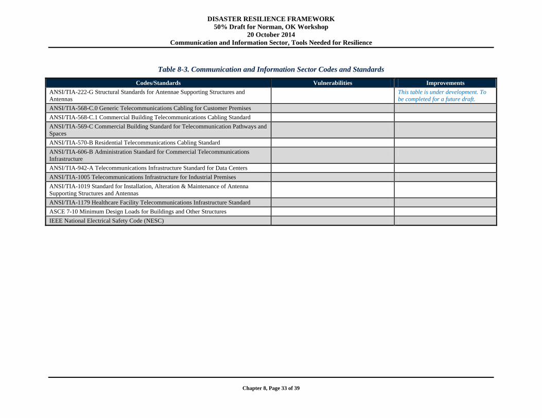
DISASTER RESILIENCE FRAMEWORK 50% Draft for Norman, OK Workshop
20 October 2014 Communication and Information Sector, Tools Needed for Resilience
Chapter 8, Page 33 of 39
Table 8-3. Communication and Information Sector Codes and Standards
Codes/Standards Vulnerabilities Improvements
ANSI/TIA-222-G Structural Standards for Antennae Supporting Structures and Antennas
This table is under development. To be completed for a future draft.
ANSI/TIA-568-C.0 Generic Telecommunications Cabling for Customer Premises
ANSI/TIA-568-C.1 Commercial Building Telecommunications Cabling Standard
ANSI/TIA-569-C Commercial Building Standard for Telecommunication Pathways and Spaces
ANSI/TIA-570-B Residential Telecommunications Cabling Standard
ANSI/TIA-606-B Administration Standard for Commercial Telecommunications Infrastructure
ANSI/TIA-942-A Telecommunications Infrastructure Standard for Data Centers
ANSI/TIA-1005 Telecommunications Infrastructure for Industrial Premises
ANSI/TIA-1019 Standard for Installation, Alteration & Maintenance of Antenna Supporting Structures and Antennas
ANSI/TIA-1179 Healthcare Facility Telecommunications Infrastructure Standard
ASCE 7-10 Minimum Design Loads for Buildings and Other Structures
IEEE National Electrical Safety Code (NESC)
DISASTER RESILIENCE FRAMEWORK 50% Draft for Norman, OK Workshop
20 October 2014 Communication and Information Sector, Tools Needed for Resilience
Chapter 8, Page 34 of 39
8.7.2. Practice Gaps and Research Needs
As discussed throughout this chapter, a number of practice gaps and research needs exist for the communication and information system infrastructure. The practice gaps discussed throughout this chapter can be broken down into construction and non-construction practice gaps.
Construction Practice Gaps. Some of the main construction practice gaps include:
Partial or complete failures of buildings housing critical equipment (e.g., central offices, exchanges, nodes)
Non-hardened rooms within buildings that house critical equipment Design loads of older cell towers that would not meet the ANSI/TIA-222-G (same as ASCE 7)
criteria Single points of failure in the distribution system Placement of distribution lines
As seen in the above list, ensuring that buildings housing critical equipment (e.g., central offices and exchanges) are hardened to resist loads of the “extreme” natural disasters is not typically done. However, examples show that when a central office has been hardened, it has been successful (see Section 8.2.1 and City of New York 2013). In cases where it is not feasible to harden an entire building against the “extreme” loads as defined in Chapter 3, it may be sufficient to harden the rooms where the critical equipment is stored against extreme loads, whether they be wind, earthquake, fire, blast, etc.
Another practice gap that should be evaluated is earthquake loading criteria that was used for cell towers designed and constructed prior to the 2006 version of ANSI/TIA-222-G. Prior to the 2006 version of ANSI/TIA-222-G, this standard did not provide design loading for earthquake. It is assumed that the designer would use ASCE design loads in place of this, but it is possible that insufficient loads from another source were used in design or earthquake loads were not addressed. Therefore, older cell towers in earthquake prone regions should be evaluated to determine if they can resist the “expected” earthquake loading.
Placement of distribution lines is a practice gap that service providers are aware of and have been addressing in recent years. The overhead versus underground utilities debate is ongoing. Some communities have conducted studies and documented their evaluation of the social and financial factors that influenced their decisions. The City of Urbana Public Works Department (2001) report provides a good example of a community working with its service providers (electric power in the case of this study) to understand and weigh the advantages and disadvantages of converting from an overhead to underground distribution systems.
Non-Construction Practice Gaps. Non-construction practice gaps include:
Poorly placed/secured critical equipment within central offices. Placing and securing cell tower standby power and switchgear such that they are not vulnerable to the
expected event. Inadequate standby power availability for cell towers
As discussed in this chapter, Hurricane Sandy among other disaster events has made it evident that critical equipment within central offices or exchanges is not always placed to minimize its vulnerability to relevant disasters. However, some service providers have placed and secured their critical equipment successfully so that disasters such as flood and earthquake do not render it useless. The whole industry should be encouraged to learn from the success stories such as that of the Verizon central office in Manhattan after Hurricane Sandy (City of New York 2013).
DISASTER RESILIENCE FRAMEWORK 50% Draft for Norman, OK Workshop
20 October 2014 Communication and Information Sector, Tools Needed for Resilience
Chapter 8, Page 35 of 39
Similarly, standby generators and switchgear used for cell towers in the event of a loss of external power should also be placed and secured such that they are not impacted by the “expected” event as defined in Chapter 3. However, as illustrated by Figure 8-7 in Section 8.2.3.1, standby generators and electrical switchgear are often located at the base on the cell tower because there is nowhere else to put them. This may be sufficient for some disaster events, such as a high wind event. However, flood events may lead to failure of the electrical switchgear and earthquakes could lead to failure if the generator and switchgear is not adequately mounted to the foundation.
Inadequate standby power supply for cell towers is another practice gap. As discussed in Section 8.2.3, the FCC attempted to mandate that all cell towers have a minimum of 8 hours of standby power for events when external power is lost; however, that mandate was overturned by the courts.
Research Needs. The main research need that is essential in improving the resilience of the communications networks is widely used and accepted tools and metrics. The tools and metrics that need be developed and validated should be capable of supporting multiple end-users, including service providers, planners, and community stakeholder panels (such as those that would ideally develop the performance goals for a given community). The tools should have the capability of simulating scenarios input by the user and compute a resulting disruption of the network (i.e., a metric). The disruption time metric may not have to be as specific as hours, but should at least be quantified in days. An ideal tool would also account for intra- and interdependencies of the system as a whole.
Although to date there are not widely used tools that model the communications system and consider all of the intra- and interdependencies, tools have been developed that can model how a system will behave in a disaster event. The Network Simulation Modeling and Analysis Research Tool (N-SMART) developed by Bell Laboratories as a part of its work with the National Infrastructure Simulation and Analysis Center provides a great example of a tool that can be used to model and understand the impact that a given event will have on a communications network (Jrad et al. 2006). N-SMART has been used by Jard et al. (2005 and 2006) to simulate the capacity, blocking levels, retrying of calls (i.e., retrials), and time to complete calls for both wireline and wireless networks. One excellent aspect of the tool is that it takes into account behavior of the users in disaster events to reflect the potential overloads.
Jard et al. (2005) use N-SMART in a study to understand the impact of having different levels of a redundant telecommunications system in a mid-size metropolitan area. That is, the study uses the tool to compare the modeled performance of both the landline and cellular network for two cases: 1) The landline network has a large number of users and the cellular network has a small number of users, and 2) the landline and cellular networks have similar numbers of users. The results of the study showed that the resiliency of the overall communications network is best when the landline and cellular networks are approximately equal in terms of use and capacity. If one network is much larger than the other and that network experiences a disruption, the demand will shift to the other network and cause congestion/overload such that it also experiences a disruption (Jard et al. 2005).
Jard et al. (2006) also used N-SMART to model the resilience of telecommunications infrastructure during different types of disaster events, including a major earthquake or 9-11 event, a major evacuation such as that seen in Houston prior to Hurricane Rita in 2005, and another smaller event where the emergency response network (i.e., 9-1-1) was overloaded resulting in poor service. This study shows that diversity of disaster events for which the tool can be used and the findings illustrate that human behavior significantly impacts the capacity and functionality of the communications infrastructure in the wake of a disaster event.
A tool comparable to N-SMART would be very helpful to service providers so they could model their communications infrastructure system and understand how it will perform in a specific disaster event/scenario. By allowing the service provider to understand how their network will perform under increased demand due to a disaster event, mitigation techniques may be explored to limit the resulting
DISASTER RESILIENCE FRAMEWORK 50% Draft for Norman, OK Workshop
20 October 2014 Communication and Information Sector, Summary and Recommendations
Chapter 8, Page 36 of 39
congestion/overload of the network. A tool with these capabilities could also help service providers in establishing its growth/marketing strategy so their network remains functional in the event of a disaster. In recent years, telecommunications services have been moving from a largely wireline (i.e., landline) service to cellular services (Jard et al. 2005 and 2006). Recalling that one of the key findings of Jard et al. (2005) was that roughly equal wireline and cellular network sizes improves resilience, service providers should be wary of growing their services such that a massive cellular network is available, with only a small wireline network.
Service providers and communities could jointly use a tool with similar capabilities to those of N-SMART to plan for and develop strategies for large evacuations, such as those that sometimes take place in advance of a hurricane’s landfall. The community may use the model in combination with their designated emergency evacuation centers or designated evacuation routes to try to improve the capacity in those areas or along those routes. A community or service provider may decide that one of its strategies will be to educate end users so they understand how their devices work and that extreme demand may exceed the network capacity around disaster events. Making end users aware and educating them on strategies to avoid a complete loss of their communications device(s) may help reduce some of the frantic redialing that adds to the demand during disaster events (Jrad et al. 2006).
Although N-SMART provides an excellent example of the potential for a tool that could be used by service providers and/or communities to model the performance of the communications infrastructure during a given disaster event, the ideal tool would go beyond what Bell Labs has already accomplished. The tools developed for use by service providers and/or communities to evaluate/model their communications infrastructure should be expanded to include key interdependencies such as power and transportation networks so recovery times can be computed taking into account the appropriate interdependencies with other sectors.
8.8. Summary and Recommendations
The telecommunications system has changed dramatically over the past 20-30 years. Constant communication has become an essential part of people’s daily lives and becomes even more important in the immediate wake of a disaster.
Emergency response personnel need to communicate with one another and those who are injured, trapped, etc.
Individuals need to communicate with their loved ones and check on each other’s safety. Low-income, elderly, and disabled or special needs populations are primary concerns during and after
a disaster event. Businesses and organizations need to re-establish themselves quickly and re-connect with their
customers and suppliers. Local government needs to continue governance, provide updates to the community, and coordinate
with outside help via the state and/or federal government.
A number of key points are evident in this chapter with respect to the resilience of communications infrastructure:
1. Building redundancy into telecommunications infrastructure is key. 2. Ensuring buildings housing key components of the communication system are designed to, or brought
up to current day standards, including the location of standby power, switchgear etc. is critical if these important parts of the communication network are to perform as desired during and after a natural hazards event. Adoption, administration and enforcement of the latest national standards and building codes at the community level are critical to ensure properly designed and built facilities.
DISASTER RESILIENCE FRAMEWORK 50% Draft for Norman, OK Workshop
20 October 2014 Communication and Information Sector, Summary and Recommendations
Chapter 8, Page 37 of 39
3. If no redundancy is built into the network, critical components, such as a lone Central Office, should be designed or hardened to ensure that it can resist the extreme load (see Chapter 3) for a given hazard faced by the community.
4. Service providers (or communities) can implement a number of strategies to be successful in mitigating service interruptions during and after a disaster event. Both construction and non-construction strategies can and should be used.
5. There is a need for tools and metrics for use by service providers and communities to understand the capacity and expected performance during and after a disaster event. Research should be conducted to develop these tools and metrics.
The following are recommended for consideration by communities:
Bring together a group of stakeholders to form a Communication Infrastructure Council. The first step is to get key entities, such as the service providers, building officials, and local
government, involved in the process early and often. If stakeholders work together so the entire community benefits, including themselves, the council is much more likely to succeed.
An assessment of the current state of the Communications Infrastructure and its vulnerabilities within the community should be completed. This activity can be carried out by the Communication Infrastructure Council. The example table of recommended performance goals in this chapter can be used as a tool to
identify the gaps between the actual and desired levels of resilience of a component of the system. The community can then use their findings to prioritize their needs and develop an action plan to make improvements over time with available funding.
The community can also adjust the recommended performance goals to fit the needs of that individual community.
Look for opportunities to add redundancy to existing systems. Funding is always an issue, so there is no expectation that everything will change at once.
However, communities and service providers should work to look for opportunities to add redundancy to components of their infrastructure whenever possible. Redundant systems allow for a better chance of continued service in the event of a failure of a part of the system.
Buildings and structures are designed to minimum criteria to resist hazards based on the applicable codes and standards (e.g., ASCE 7). If the structure being designed is known to be a single point of failure in the last/first mile, the owner should consider having the structure hardened or designed to a higher standard. In Chapter 3 of this Framework, we provide definitions for different magnitudes of hazard. The nominal design criteria presented in correspond to the “expected” event but load and resistance factors (or safety factors) have been applied so it is expected that structures built to these standards will survive without damage sufficient to cause service interruption during the extreme event. However, for single points of failure, it is suggested that the design criteria should be consistent with the “extreme” event (ASCE Occupancy Category IV).
Service providers may be owners of Central Offices and/or other buildings, but these properties are often leased. Therefore, the building owners who lease to service providers should understand the needs of their tenants (i.e., service providers) to ensure their critical equipment is not crippled in a disaster event.
The design and placement of key electrical components, standby power, etc. needs to be consistent with the overall performance goals of the building as a whole. In the case of flooding, for example, meeting the ASCE 7 design criteria and providing a risk consistent structural design requires placing critical equipment, electric panels, emergency equipment etc., at the appropriate height above the BFE or flood proofing the structure to prevent water intrusion during the extreme event.
DISASTER RESILIENCE FRAMEWORK 50% Draft for Norman, OK Workshop
20 October 2014 Communication and Information Sector, References
Chapter 8, Page 38 of 39
Service providers and communities have a number of options so that they can successfully improve the resilience of their communications infrastructure. Service providers and communities are encouraged to consider the following mitigation strategies to improve their communication infrastructure resilience:
Design new/future buildings that house Central Offices and other exchanges/nodes in the communications infrastructure system such that they resist the loads associated with the appropriate disaster level and performance goals. When the service providers own these buildings, they can work directly with the building
designers to ensure the building meets the appropriate loading criteria so that the performance goals for resilience can be met.
When service providers commit to leasing a new/future building from a third party, service providers can attempt to work with the building owner to ensure that the sections of the building they have committed to leasing are designed (i.e., hardened) to resist the appropriate loads.
Harden existing buildings owned by service providers that house Central Offices and other exchanges/nodes in the communications infrastructure system to resist the appropriate loads to meet the performance goals.
Place and secure critical equipment in Central Offices such that it is not vulnerable to the hazards faced by the community, whether flooding, earthquake, etc.
Design or retrofit cell towers, as needed, to ensure they resist the loads associated with the “expected” hazard level
Ensure 8+ hours of standby power is available for cell towers so that they can function for a reasonable period of time in the immediate aftermath of a disaster event
Place and secure cell tower standby power and switchgear such that they are not impacted by the “expected” event.
Ensure distribution lines have redundancy (path diversity) built into the network Place distribution lines so that their vulnerability to natural hazards is minimized.
8.9. References
Anixter Inc., (2013). Standards Reference Guide. Glenview, Illinois.
American Lifelines Alliance (2006). Power Systems, Water, Transportation and Communications Lifeline Interdependencies – Draft Report. Washington, DC.
American Society of Civil Engineers (ASCE 2010). ASCE 7-10, Minimum Design Loads for Buildings and Other Structures, Second Edition. New York, New York.
AT&T (2014). Viewed August 28, 2014. < http://www.corp.att.com/ndr/deployment1.html>.
AT&T (2005). Best Practices: AT&T Network Continuity Overview.
The City of New York (2013). A Stronger, More Resilient New York. New York City, NY.
City of Urbana Public Works Department (2001). Overhead to Underground Utility Conversion. Urbanaa, Illinois.
East Tennessee State University Office of Information Technology (ETSU 2014). Telecommunications Design and Installation Standards Policy.
Erichsen, John R. Slideshow Presentation: ANSI/TIA-222-G Explained. Viewed July 5, 2014.
Fiber-to-the-Home Council (FTTH Council 2013). Comments of the Fiber-to-the Home Council on Request to Refresh Record and Amend the Commission’s Copper Retirement Rules. Washington, DC.
Hubbell Premise Wiring Inc. Structured Cabling Standards and Practices. Viewed July 5, 2014.
DISASTER RESILIENCE FRAMEWORK 50% Draft for Norman, OK Workshop
20 October 2014 Communication and Information Sector, References
Chapter 8, Page 39 of 39
Jrad, Ahman et al. (2005). Wireless and Wireline Network Interactions in Disaster Scenarios. Military Communications Conference. Washington, DC.
Jrad, Ahman et al. (2006). Dynamic Changes in Subscriber Behavior and their Impact on the Telecom Network in Cases of Emergency. Military Communications Conference. Washington, DC.
Kende, Michael, and Hurpy, Charles (2012). Assessment of the Impact of Internet Exchange Points – Empirical Study of Kenya and Nigeria. Analysys Mason Limited. Washington, DC.
Kentucky Public Service Commission (2009). The Kentucky Public Service Commission Report on the September 2008 Wind Storm and the January 2009 Ice Storm.
Lower Manhattan Telecommunications Users’ Working Group Findings and Recommendations (2002). Building a 21st Century Telecom Infrastructure. Ney York City, NY.
Mehta, Kishor (2010). Wind Load History ANSI A58.1-1972 to ASCE 7-05. Structures Congress, American Society of Civil Engineers.
Oregon Seismic Safety Policy Advisory Commission (OSSPAC 2013). The Oregon Resilience Plan: Reducing Risk and Improving Recovery for the Next Cascadia Earthquake and Tsunami. Salem, Oregon.
The Lifelines Council of the City and County of San Francisco (2014). Lifelines Interdependency Study Report I. San Francisco, California.
Federal Communications Commission (FCC 2011). <www.fcc.gov/telecom.html>. Viewed on July 5, 2014. Telecommunications Act of 1996.
Federal Emergency Management Agency (FEMA 2013). Mitigation Assessment Team Report: Hurricane Sandy in New Jersey and New York. Washington, DC.
Stephan, Karl D (2007). We’ve got to Talk: Emergency Communications and Engineering Ethics. IEEE Technology and Society Magazine.
Telecommunications Industry Association (TIA 2014). TR-14 Structural Standards for Communication and Small Wind Turbine Support Structures. Viewed September 22, 2014. <http://www.tiaonline.org/all-standards/committees/tr-14>.
Wahba, John et al. (2003). New Standards for Broadcast Structures ANSI/EIA/TIA-222-G.
West Virginia Broadband (2013). Viewed July 5, 2014. <http://www.westvirginia.com/broadband/mediaroom/BroadbandGlossary.pdf>.
Victory, Nancy et al. (2006). Report and Recommendations of the Interdependent Panel Reviewing the Impact of Hurricane Katrina on Communications Networks. Washington, DC.