Embed Size (px)
Citation preview

1
8. Strain Transformation
• Apply the stress transformation methods derived in Chapter 9 to similarly transform strain
• Discuss various ways of measuring strain
• Develop important material-property relationships; including generalized form of Hooke’s law
CHAPTER OBJECTIVES

2
8. Strain Transformation
CHAPTER OUTLINE
1. Plane Strain
2. General Equations of Plane-Strain Transformation
3. Strain Rosettes
4. Material-Property Relationships

3
8. Strain Transformation
10.1 PLANE STRAIN
• As explained in Chapter 2.2, general state of strain in a body is represented by a combination of 3 components of normal strain (x, y, z), and 3 components of shear strain (xy, xz, yz).
• Strain components at a pt determined by using strain gauges, which is measured in specified directions.
• A plane-strained element is subjected to two components of normal strain (x, y) and one component of shear strain, xy.

4
8. Strain Transformation
10.1 PLANE STRAIN
• The deformations are shown graphically below.• Note that the normal strains are produced by
changes in length of the element in the x and y directions, while shear strain is produced by the relative rotation of two adjacent sides of the element.

5
8. Strain Transformation
10.1 PLANE STRAIN
• Note that plane stress does not always cause plane strain.
• In general, unless = 0, the Poisson effect will prevent the simultaneous occurrence of plane strain and plane stress.
• Since shear stress and shear strain not affected by Poisson’s ratio, condition of xz = yz = 0 requires xz = yz = 0.

6
8. Strain Transformation
10.2 GENERAL EQNS OF PLANE-STRAIN TRANSFORMATION
Sign Convention• To use the same convention as
defined in Chapter 2.2.• With reference to differential
element shown, normal strains x and y are positive if they cause elongation along the x and y axes
• Shear strain xy is positive if the interior angle AOB becomes smaller than 90.

7
8. Strain Transformation
10.2 GENERAL EQNS OF PLANE-STRAIN TRANSFORMATION
Sign Convention• Similar to plane stress, when measuring the normal
and shear strains relative to the x’ and y’ axes, the angle will be positive provided it follows the curling of the right-hand fingers, counterclockwise.
Normal and shear strains• Before we develop the
strain-transformation eqn for determining x;, we must determine the elongation of a line segment dx’ that lies along the x’ axis and subjected to strain components.

8
8. Strain Transformation
10.2 GENERAL EQNS OF PLANE-STRAIN TRANSFORMATION
Normal and shear strains• Components of line dx and dx’ are elongated and
we add all elongations together.
• From Eqn 2.2, the normal strain along the line dx’ is x’ =x’/dx’. Using Eqn 10-1,
cossincos' dydydxx xyyx
210cossinsincos 22' - xyyxx

9
8. Strain Transformation
10.2 GENERAL EQNS OF PLANE-STRAIN TRANSFORMATION
Normal and shear strains
• To get the transformation equation for x’y’, consider amount of rotation of each of the line segments dx’ and dy’ when subjected to strain components. Thus, sincossin' dydydxy xyyx

10
8. Strain Transformation
10.2 GENERAL EQNS OF PLANE-STRAIN TRANSFORMATION
Normal and shear strains• Using Eqn 10-1 with = y’/x’,
• As shown, dy’ rotates by an amount .
310sincossin 2 - xyyx
11
8. Strain Transformation
10.2 GENERAL EQNS OF PLANE-STRAIN TRANSFORMATION
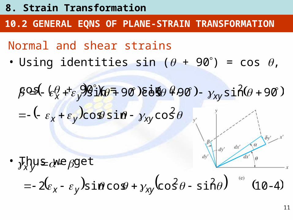
Normal and shear strains• Using identities sin ( + 90) = cos ,
cos ( + 90) = sin ,
• Thus we get
2
2
cossincos
90sin90cos90sin
xyyx
xyyx
410sincoscossin2 22
''
-
xyyx
yx

12
8. Strain Transformation
10.2 GENERAL EQNS OF PLANE-STRAIN TRANSFORMATION
Normal and shear strains• Using trigonometric identities sin 2 = 2 sin cos,
cos2 = (1 + cos2 )/2 and sin2 + cos2 = 1, we rewrite Eqns 10-2 and 10-4 as
5102sin2
2cos22' -
xyyxyx
x
6-102cos2
2sin22
''
xyyxyx

13
8. Strain Transformation
10.2 GENERAL EQNS OF PLANE-STRAIN TRANSFORMATION
Normal and shear strains• If normal strain in the y direction is required, it can
be obtained from Eqn 10-5 by substituting ( + 90) for . The result is
6102sin2
2cos22' -
xyyxyx
y
14
8. Strain Transformation
10.2 GENERAL EQNS OF PLANE-STRAIN TRANSFORMATION
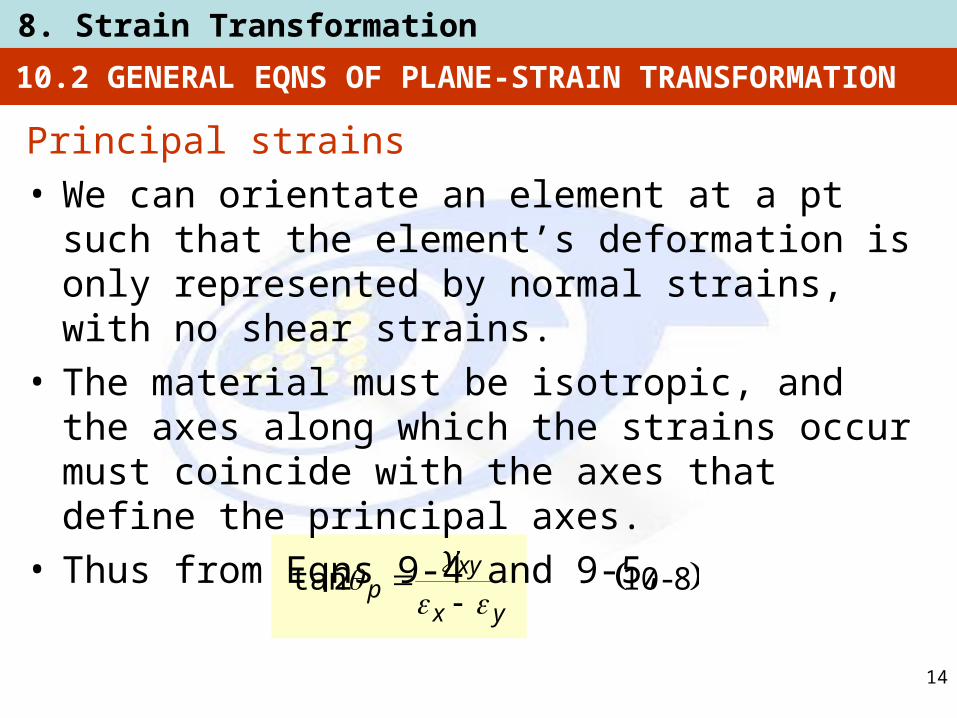
Principal strains• We can orientate an element at a pt such that the
element’s deformation is only represented by normal strains, with no shear strains.
• The material must be isotropic, and the axes along which the strains occur must coincide with the axes that define the principal axes.
• Thus from Eqns 9-4 and 9-5,
8102tan -yx
xyp

15
8. Strain Transformation
10.2 GENERAL EQNS OF PLANE-STRAIN TRANSFORMATION
Principal strains
Maximum in-plane shear strain• Using Eqns 9-6, 9-7 and 9-8, we get
910222
22
2,1 -
xyyxyx
1110222
22plane-in
max
-
xyyx
10102tan -
xy
yxs

16
8. Strain Transformation
10.2 GENERAL EQNS OF PLANE-STRAIN TRANSFORMATION
Maximum in-plane shear strain• Using Eqns 9-6, 9-7 and 9-8, we get
12102
-avgyx
17
8. Strain Transformation
10.2 GENERAL EQNS OF PLANE-STRAIN TRANSFORMATION
IMPORTANT• Due to Poisson effect, the state of plane strain is
not a state of plane stress, and vice versa.• A pt on a body is subjected to plane stress when
the surface of the body is stress-free.• Plane strain analysis may be used within the plane
of the stresses to analyze the results from the gauges. Remember though, there is normal strain that is perpendicular to the gauges.
• When the state of strain is represented by the principal strains, no shear strain will act on the element.
18
8. Strain Transformation
10.2 GENERAL EQNS OF PLANE-STRAIN TRANSFORMATION
IMPORTANT• The state of strain at the pt can also be represented
in terms of the maximum in-plane shear strain. In this case, an average normal strain will also act on the element.
• The element representing the maximum in-plane shear strain and its associated average normal strains is 45 from the element representing the principal strains.
19
8. Strain Transformation
EXAMPLE 10.1
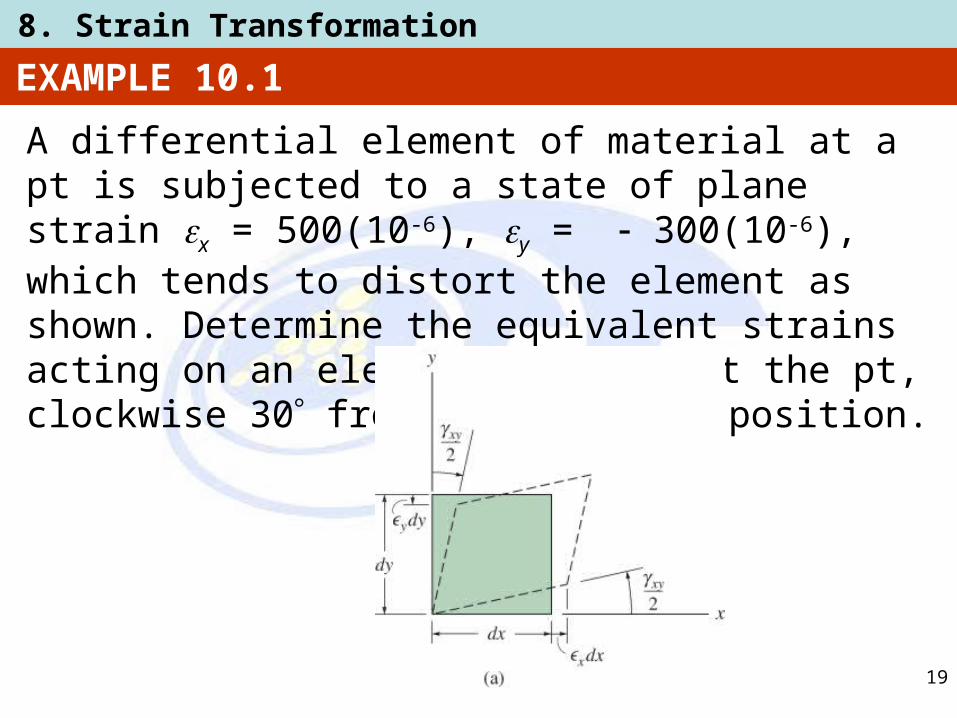
A differential element of material at a pt is subjected to a state of plane strain x = 500(10-6), y = 300(10-6), which tends to distort the element as shown. Determine the equivalent strains acting on an element oriented at the pt, clockwise 30 from the original position.

20
8. Strain Transformation
EXAMPLE 10.1 (SOLN)
• Since is counterclockwise, then = –30, use strain-transformation Eqns 10-5 and 10-6,
6'
6
6
6
'
10213
302sin210200
302cos102
300500
102
300500
2sin2
2cos22
x
xyyxyxx

21
8. Strain Transformation
EXAMPLE 10.1 (SOLN)
• Since is counterclockwise, then = –30, use strain-transformation Eqns 10-5 and 10-6,
6''
6
''
10793
302cos210200
302sin2
300500
2cos2
2sin22
yx
xyyxyx

22
8. Strain Transformation
EXAMPLE 10.1 (SOLN)
• Strain in the y’ direction can be obtained from Eqn 10-7 with = –30. However, we can also obtain y’ using Eqn 10-5 with = 60 ( = –30 + 90), replacing x’ with y’
6'
6
6
6'
104.13
602sin210200
602cos102
300500
102
300500
y
y

23
8. Strain Transformation
EXAMPLE 10.1 (SOLN)
• The results obtained tend to deform the element as shown below.

24
8. Strain Transformation
EXAMPLE 10.2
A differential element of material at a pt is subjected to a state of plane strain defined by x = –350(10-6), y = 200(10-6), xy = 80(10-6), which tends to distort the element as shown. Determine the principal strains at the pt and associated orientation of the element.

25
8. Strain Transformation
EXAMPLE 10.2 (SOLN)
Orientation of the element
From Eqn 10-8, we have
Each of these angles is measured positive counterclockwise, from the x axis to the outward normals on each face of the element.
9.8514.4
,17218028.828.82
)10(200350
)10(802tan
6
6
and
thatsoandThus
p
p
yx
xyp

26
8. Strain Transformation
EXAMPLE 10.2 (SOLN)
Principal strains
From Eqn 10-9,
6
26
1
66
6226
22
2,1
1035310203
109.277100.75
102
802
2003502
10200350
222
xyyxyx

27
8. Strain Transformation
EXAMPLE 10.2 (SOLN)
Principal strains
We can determine which of these two strains deforms the element in the x’ direction by applying Eqn 10-5 with = –4.14. Thus
6'
6
66
'
10353
14.42sin2
1080
14.4cos102
20035010
2200350
2sin2
2cos22
x
xyyxyxx

28
8. Strain Transformation
EXAMPLE 10.2 (SOLN)
Principal strains
Hence x’ = 2. When subjected to the principal strains, the element is distorted as shown.

29
8. Strain Transformation
EXAMPLE 10.3
A differential element of material at a pt is subjected to a state of plane strain defined by x = –350(10-6), y = 200(10-6), xy = 80(10-6), which tends to distort the element as shown. Determine the maximum in-plane shear strain at the pt and associated orientation of the element.

30
8. Strain Transformation
EXAMPLE 10.3 (SOLN)
Orientation of the element
From Eqn 10-10,
Note that this orientation is 45 from that shown in Example 10.2 as expected.
9.1309.40
,72.26118072.8172.812
1080
102003502tan
6
6
and
thatsoandThus,
s
s
xy
yxs

31
8. Strain Transformation
EXAMPLE 10.3 (SOLN)
Maximum in-plane shear strainApplying Eqn 10-11,
The proper sign of can be obtained by applying Eqn 10-6 with s = 40.9.
6
622
22
10556
102
802
200350
222
plane-in
max
plane-in
max
xyyx
plane-in
max

32
8. Strain Transformation
EXAMPLE 10.3 (SOLN)
Maximum in-plane shear strain
Thus tends to distort the element so that the right angle between dx’ and dy’ is decreased (positive sign convention).
6''
6
6
''
10556
9.402cos2
1080
9.402sin102
200350
2cos2
2sin22
yx
xyyxyx
plane-in
max

33
8. Strain Transformation
EXAMPLE 10.3 (SOLN)
Maximum in-plane shear strain
There are associated average normal strains imposed on the element determined from Eqn 10-12:
These strains tend to cause the element to contract.
66 1075102
2003502
yx avg

34
8. Strain Transformation
• We measure the normal strain in a tension-test specimen using an electrical-resistance strain gauge.
• For general loading on a body, the normal strains at a pt are measured using a cluster of 3 electrical-resistance strain gauges.
• Such strain gauges, arranged in a specific pattern are called strain rosettes.
• Note that only the strains in the plane of the gauges are measured by the strain rosette. That is ,the normal strain on the surface is not measured.
10.5 STRAIN ROSETTES

35
8. Strain Transformation
10.5 STRAIN ROSETTES
• Apply strain transformation Eqn 10-2 to each gauge:
• We determine the values of x, y xy by solving the three equations simultaneously.
1610cossinsincos
cossinsincos
cossinsincos
22
22
22
-ccxycycxc
bbxybybxb
aaxyayaxa

36
8. Strain Transformation
10.5 STRAIN ROSETTES
• For rosettes arranged in the 45 pattern, Eqn 10-16 becomes
• For rosettes arranged in the 60 pattern, Eqn 10-16 becomes
cabxy
cy
ax
2
17103
2
2231
-cbxy
acby
ax

37
8. Strain Transformation
EXAMPLE 10.8
State of strain at pt A on bracket is measured using the strain rosette shown. Due to the loadings, the readings from the gauges give a = 60(10-6), b = 135(10-6), and c = 264(10-6). Determine the in-plane principal strains at the pt and the directions in which they act.

38
8. Strain Transformation
EXAMPLE 10.8 (SOLN)
Establish x axis as shown, measure the angles counterclockwise from the +x axis to center-lines of each gauge, we have a = 0, b = 60, and c = 120Substitute into Eqn 10-16,
)3(433.075.025.0
120cos120sin120sin120cos10264
)2(433.075.025.0
60cos60sin60sin60cos10135
)1(0cos0sin0sin0cos1060
226
226
226
xyyx
xyyx
xyyx
xyyx
xxyyx

39
8. Strain Transformation
Solving Eqns (1), (2) and (3) simultaneously, we get
The in-plane principal strains can also be obtained directly from Eqn 10-17. Reference pt on Mohr’s circle is A [60(10-6), –74.5(10-6)] and center of circle, C is on the axis at avg = 153(10-6). From shaded triangle, radius is
EXAMPLE 10.8 (SOLN)
666 10149102461060 xyyx
6
622
102.119
105.7460153
R
R

40
8. Strain Transformation
The in-plane principal strains are thus
Deformed element is shown dashed. Due to Poisson effect, element also subjected to an out-of-plane strain, in the z direction, although this value does not influence the calculated results.
EXAMPLE 10.8 (SOLN)
3.19
7.3860153
5.74tan2
108.33102.11910246
10272102.11910153
2
12
6662
6661
p
p

41
8. Strain Transformation
10.6 MATERIAL-PROPERTY RELATIONSHIPS
Generalized Hooke’s law• Material at a pt subjected to a state of triaxial
stress, with associated strains.• We use principle of superposition, Poisson’s ratio
(lat = long), and Hooke’s law ( = E) to relate stresses to strains, in the uniaxial direction.
• With x applied, element elongates in the x direction and strain is this direction is
Ex
x '

42
8. Strain Transformation
10.6 MATERIAL-PROPERTY RELATIONSHIPS
Generalized Hooke’s law
• With y applied, element contracts with a strain ‘’x in the x direction,
• Likewise, With z applied, a contraction is caused in the z direction,
Ey
x
''
Ez
x '''

43
8. Strain Transformation
10.6 MATERIAL-PROPERTY RELATIONSHIPS
Generalized Hooke’s law• By using the principle of superposition,
yxzz
zxyy
zyxx
E
E
E
1
18101
1
-
44
8. Strain Transformation
10.6 MATERIAL-PROPERTY RELATIONSHIPS
Generalized Hooke’s law
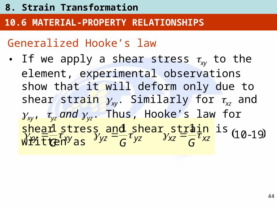
• If we apply a shear stress xy to the element, experimental observations show that it will deform only due to shear strain xy. Similarly for xz and xy, yz and yz. Thus, Hooke’s law for shear stress and shear strain is written as
1910111
-xzxzyzyzxyxy GGG

45
8. Strain Transformation
10.6 MATERIAL-PROPERTY RELATIONSHIPS
Relationship involving E, , and G• We stated in chapter 3.7:
• Relate principal strain to shear stress,
• Note that since x = y = z = 0, then from Eqn 10-18, x = y = 0. Substitute into transformation Eqn 10-19,
2010
12-
E
G
21101max -
Exy
2max1xy

46
8. Strain Transformation
Relationship involving E, , and G
• By Hooke’s law, xy = xy/G. So max = xy/2G.
• Substitute into Eqn 10-21 and rearrange to obtain Eqn 10-20.
Dilatation and Bulk Modulus• Consider a volume element subjected to principal
stresses x, y, z.
• Sides of element are dx, dy and dz, and after stress application, they become (1 + x)dx, (1 + y)dy, (1 + z)dz, respectively.
10.6 MATERIAL-PROPERTY RELATIONSHIPS

47
8. Strain Transformation
10.6 MATERIAL-PROPERTY RELATIONSHIPS
Dilatation and Bulk Modulus• Change in volume of element is
• Change in volume per unit volume is the “volumetric strain” or dilatation e.
• Using generalized Hooke’s law, we write the dilatation in terms of applied stress.
dzdydxdzdydxV zyx 111
2210 -zyxdVV
e
231021
-zyxEe

48
8. Strain Transformation
10.6 MATERIAL-PROPERTY RELATIONSHIPS
Dilatation and Bulk Modulus• When volume element of material is subjected to
uniform pressure p of a liquid, pressure is the same in all directions.
• As shear resistance of a liquid is zero, we can ignore shear stresses.
• Thus, an element of the body is subjected to principal stresses x = y = z = –p. Substituting into Eqn 10-23 and rearranging,
2410
213-
E
ep

49
8. Strain Transformation
10.6 MATERIAL-PROPERTY RELATIONSHIPS
Dilatation and Bulk Modulus• This ratio (p/e) is similar to the ratio of linear-elastic
stress to strain, thus terms on the RHS are called the volume modulus of elasticity or the bulk modulus. Having same units as stress with symbol k,
• For most metals, ≈ ⅓ so k ≈ E.
• From Eqn 10-25, theoretical maximum value of Poisson’s ratio is therefore = 0.5.
• When plastic yielding occurs, = 0.5 is used.
2510
213-
E
k

50
8. Strain Transformation
10.6 MATERIAL-PROPERTY RELATIONSHIPS
IMPORTANT• When homogeneous and isotropic material is
subjected to a state of triaxial stress, the strain in one of the stress directions is influence by the strains produced by all stresses. This is the result of the Poisson effect, and results in the form of a generalized Hooke’s law.
• A shear stress applied to homogenous and isotropic material will only produce shear strain in the same plane.
• Material constants, E, G and are related mathematically.
51
8. Strain Transformation
10.6 MATERIAL-PROPERTY RELATIONSHIPS
IMPORTANT• Dilatation, or volumetric strain, is caused by only by
normal strain, not shear strain.• The bulk modulus is a measure of the stiffness of a
volume of material. This material property provides an upper limit to Poisson’s ratio of = 0.5, which remains at this value while plastic yielding occurs.

52
8. Strain Transformation
EXAMPLE 10.10
Copper bar is subjected to a uniform loading along its edges as shown. If it has a length a = 300 mm, width b = 50 mm, and thickness t = 20 mm before the load is applied, determine its new length, width, and thickness after application of the load. Take Ecu = 120 GPa, cu = 0.34.

53
8. Strain Transformation
EXAMPLE 10.10 (SOLN)
By inspection, bar is subjected to a state of plane stress. From loading, we have
Associated strains are determined from generalized Hooke’s law, Eqn 10-18;
00500800 zxyyx MPaMPa
00808.0500
10312034.0
103120800
MPaMPa
MPa
zvx
x EE

54
8. Strain Transformation
EXAMPLE 10.10 (SOLN)
Associated strains are determined from generalized Hooke’s law, Eqn 10-18;
00850.0500800
10312034.0
0
00643.080010312034.0
103120500
MPaMPa
MPaMPa
MPa
yxz
z
zxy
y
EE
EE

55
8. Strain Transformation
EXAMPLE 10.10 (SOLN)
The new bar length, width, and thickness are
mmmmmm
mmmmmm
mmmmmm
98.1920000850.020'
68.495000643.050'
4.30230000808.0300'
t
b
a

56
8. Strain Transformation
EXAMPLE 10.11
If rectangular block shown is subjected to a uniform pressure of p = 20 kPa, determine the dilatation and change in length of each side. Take E = 600 kPa, = 0.45.

57
8. Strain Transformation
EXAMPLE 10.11 (SOLN)
Dilatation
The dilatation can be determined using Eqn 10-23 with x = y = z = –20 kPa. We have
33 /01.0
203600
45.021
21
cmcm
kPakPa
zyxEe

58
8. Strain Transformation
EXAMPLE 10.11 (SOLN)
Change in length
Normal strain on each side can be determined from Hooke’s law, Eqn 10-18;
cm/cm
kPakPakPakPa
00333.0
202045.020600
1
1
zyxE

59
8. Strain Transformation
EXAMPLE 10.11 (SOLN)
Change in length
Thus, the change in length of each side is
The negative signs indicate that each dimension is decreased.
cmcm
cmcm
cmcm
0100.0300333.0
00667.0200333.0
0133.0400333.0
c
b
a
60
8. Strain Transformation
CHAPTER REVIEW
• When element of material is subjected to deformations that only occur in a single plane, then it undergoes plain strain.
• If the strain components x, y, and xy are known for a specified orientation of the element, then the strains acting for some other orientation of the element can be determined using the plane-strain transformation equations.
• Likewise, principal normal strains and maximum in-plane shear strain can be determined using transformation equations.

61
8. Strain Transformation
CHAPTER REVIEW
• Hooke’s law can be expressed in 3 dimensions, where each strain is related to the 3 normal stress components using the material properties E, and , as seen in Eqns 10-18.
• If E and are known, then G can be determined using G = E/[2(1 + ].
• Dilatation is a measure of volumetric strain, and the bulk modulus is used to measure the stiffness of a volume of material.

![Effect of Structural Transformation on the Mechanical and Electrical …egmrs.powweb.com/EJS/PDF/Vol302/12.pdf · 2008. 6. 4. · [9]. Tensile strain-strain tests were carried out](https://img.pdfslide.net/doc/110x75/606894ea5d36d9414b64eb22/effect-of-structural-transformation-on-the-mechanical-and-electrical-egmrs-2008.jpg)


![Strain Transformation.ppt [相容模式] - 義守大學 · Plane-Strain Transformation Strain at the same point but different coordinates 6. Strain Transformation 4 want to calculate](https://img.pdfslide.net/doc/110x75/5b939ddc09d3f2d1448dc03d/strain-plane-strain-transformation-strain-at-the.jpg)