Embed Size (px)
Citation preview
JJ 2011 J2/H1 Physics (8866) WAVE MOTION
©cfs / kpl Page 1 of 24
8. Wave Motion Content 1. Progressive Waves 2. Transverse and Longitudinal Waves 3. Polarisation 4. Determination of frequency and wavelength Learning Outcomes: Candidates should be able to: (a) show an understanding and use the terms displacement, amplitude, phase difference,
period, frequency, wavelength and speed. (b) deduce, from the definitions of speed, frequency and wavelength, the equation v = fλ. (c) recall and use the equation v = fλ. (d) show an understanding that energy is transferred due to a progressive wave. (e) recall and use the relationship, intensity ∝ (amplitude)
2.
(f) analyse and interpret graphical representations of transverse and longitudinal waves. (g) show an understanding that polarisation is a phenomenon associated with transverse
waves. (h) determine the frequency of sound using a calibrated c.r.o. (i) determine the wavelength of sound using stationary waves. Acknowledgements:
1. Comprehensive Physics for ‘A’ level (3rd edition) Vol.2 – KF Chan, Charles Chew, SH Chan (Federal Study Aids)
2. Fundamentals of Physics (6th edition) – Halliday, Resnick, Walker (John Wiley & sons, Inc.).
3. Notes Wave Motion 2009 by FS Chin ©JJ
4. 2010 J2 H2 Wave Motion Notes by KW Chong ©JJ
JJ 2011 J2/H1 Physics (8866) WAVE MOTION
©cfs / kpl Page 2 of 24
Waves vs. Particles
Two ways to get in touch with a friend in a distant city are to write a letter and to use the telephone. The first choice (the snail-mail) involves the concept of a “particle” : a material object moves from one point to another, carrying with it information and energy.
The 2nd choice (the telephone) involves the concept of “waves”. The information and energy move from one point to another but no material object makes that journey. In the telephone call, a sound wave carries your message from your vocal cords to the telephone. There, an electromagnetic wave takes over, passing along a copper wire or an optical fiber or through the atmosphere (satellite). At the receiving end, there is another sound wave, from a telephone to your friend’s ear. Although the message is passed, nothing that you have touched reaches your friend.
“It often happens that the wave flees the place of its creation, while the water does not: like the wave made in a field of grain by the wind, where we see the waves running across the field while
the grain remains in place.” ~ Leonardo da Vinci. Particle and wave are the 2 great concepts in classical physics, although the concepts are very different. The word particle suggests a tiny concentration of matter capable of transmitting energy. The word wave suggests a broad distribution of energy, filling the space through which it passes. Wave Production 1. The source of any wave is a vibration or oscillation.
2. A wave is a mechanism for the transfer of energy from one point to another without the physical transfer of any material between the points.
Types of Waves There are 3 main types: 1. Mechanical Waves. These waves are most familiar because we encounter them
almost constantly. Examples include water waves, sound waves and seismic waves. The wave motion is transmitted by the particles of the medium oscillating to and fro. Main features : (i) Newton’s laws govern them;
(ii) they can only exist within a material medium (e.g. water, air & rock) 2. Electromagnetic (EM) waves. These are less familiar, but we use them constantly.
Common examples include visible and ultraviolet light, radio and television waves, microwaves, x-rays and radar waves. The wave motion is in the form of varying electric and magnetic fields. Main features : (i) these waves require no material medium to exist
(ii) All electromagnetic waves travel through a vacuum at the same speed, c (speed of light) , i.e. c = 299 792 458 m s-1 ≈ 3 x 10⁸ m s-1.
3. Matter waves. Although these waves are commonly used in modern technology, their
type is probably very unfamiliar to us. These waves are associated with electrons, protons and other fundamental particles, even atoms and molecules. Because we commonly think of these things as constituting matter, they are called matter waves. (Not in your syllabus).
JJ 2011 J2/H1 Physics (8866) WAVE MOTION
©cfs / kpl Page 3 of 24
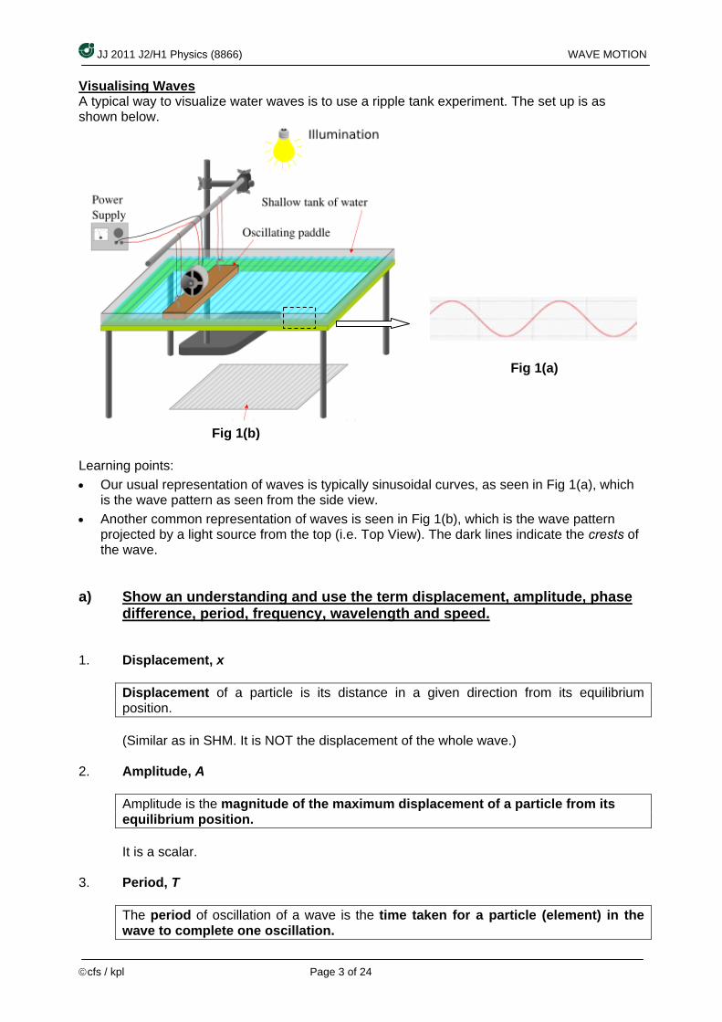
Visualising Waves A typical way to visualize water waves is to use a ripple tank experiment. The set up is as shown below.
Learning points: • Our usual representation of waves is typically sinusoidal curves, as seen in Fig 1(a), which
is the wave pattern as seen from the side view. • Another common representation of waves is seen in Fig 1(b), which is the wave pattern
projected by a light source from the top (i.e. Top View). The dark lines indicate the crests of the wave.
a) Show an understanding and use the term displacement, amplitude, phase
difference, period, frequency, wavelength and speed.
1. Displacement, x
Displacement of a particle is its distance in a given direction from its equilibrium position. (Similar as in SHM. It is NOT the displacement of the whole wave.)
2. Amplitude, A
Amplitude is the magnitude of the maximum displacement of a particle from its equilibrium position. It is a scalar.
3. Period, T
The period of oscillation of a wave is the time taken for a particle (element) in the wave to complete one oscillation.
Fig 1(a)
Fig 1(b)

JJ 2011 J2/H1 Physics (8866) WAVE MOTION
©cfs / kpl Page 4 of 24
4. Frequency, f
Frequency of a wave is the number of oscillations per unit time made by a particle (element) in the wave. The frequency of a wave is the same as the frequency of its source. It is independent of the medium through which the wave propagates.
It is related to period, T, by πω2
1==
Tf where ω = angular frequency.
5. Wavelength, λ
Wavelength of a wave is the shortest distance between two points which are in phase.
6. Speed, v
Speed of a wave is the distance travelled by the wave per unit time.
7. Phase and Phase Difference, φ
Phase difference between two points in a wave is the difference between the stages of oscillations, expressed in terms of an angle. (e.g. Two points half a wavelength apart has a phase difference of π radians)
1. Two points being in the same phase means that they are in the same state of disturbance at the same time (e.g. the points x x’ and y y’ in the diagram above). They are said to be in phase. Their phase difference is zero.
2. Two crests or two troughs are in phase, whereas a crest and an adjacent trough
are out of phase by 180° or π rad. They are said to be anti-phase. Their phase difference is 180° or π rad.

JJ 2011 J2/H1 Physics (8866) WAVE MOTION
©cfs / kpl Page 5 of 24
3. The phase difference, φ, between two particles in a wave (e.g. particle P and
another particle B, below) separated by distance x, is given by
The L.H.S is a ratio of angles in radians The denominator is the angle for a complete oscillation. The R.H.S is a ratio of distance travelled by the wave. The denominator is the distance travelled by the wave in the time for a complete oscillation, the wavelength λ.
4. The phase difference, φ, between two oscillations separated by a time t is
given by
Now the R.H.S. is a ratio of time. The denominator is the time for a complete oscillation, the period T.
(b) Deduce, from the definitions of speed, frequency and wavelength, the
equation v = fλ.
Speed, v, is the distance travelled per unit time. In the time of one period, T, the wave travels a distance of one wavelength, λ. So the speed of a wave motion can be expressed as
v = distance travelledtime taken
= λT
- - - - - (1)
Frequency f is related to period T by the relation
f = 1T
- - - - - (2)
From the relations (1) and (2) above, the speed of a wave motion can hence be expressed as
v = fλ
2tT
φπ=
πφ
λ 2=
x

JJ 2011 J2/H1 Physics (8866) WAVE MOTION
©cfs / kpl Page 6 of 24
(c) Recall and use the equation v = fλ Example 1 Visible light has wavelengths between 400 nm and 700 nm, and its speed in a vacuum is 3.0 × 10⁸ m s-1. What is the maximum frequency of visible light? Solution:
From v = fλ, the frequency f =λv , i.e. f is inversely proportional to λ.
For maximum frequency, minimum wavelength should be used.
Hence, fmax =λmin
v =−
−
××
8 1
9
3 10 m s400 10 m
= 7.5 × 10¹⁴ Hz.
Example 2 A sound wave of frequency 400 Hz is travelling in a gas at a speed of 320 m s-1. What is the phase difference between two points 0.2 m apart in the direction of travel? Solution:
Wavelength, λ = vf
=−1320 m s
400 Hz= 0.80 m
φπ2
=λx = 0.2 m
0.8 m= 1
4 φ = π
2rad
Example 3 The speed of electromagnetic (EM) waves (which include visible light, radio and x-rays) in vacuum is 3.0 x 10⁸ m s-1. a) Wavelengths of visible light waves range from about 400 nm in the violet to about 700
nm in the red. What is the range of frequencies of these waves? b) The range of frequencies for short-wave radio (e.g. Class 95 FM) is 1.5 to 300 MHz.
What is the corresponding wavelength range? c) X-ray wavelengths range from about 5.0 nm to about 1.0 x 10⁻² nm. What is the
frequency range for x-rays? Solution
a) Using v = fλ λvf =
Hz10x29.410x70010x0.3f 14
9
8
red ==∴ − & Hzxxxfviolet
149
8
1050.710400100.3
== −
Hence, range of frequencies for visible light is from 4.29 x 10¹⁴
Hz to 7.50 x 10¹⁴
Hz.
JJ 2011 J2/H1 Physics (8866) WAVE MOTION
©cfs / kpl Page 7 of 24
b) From v = fλ fv
=λ
8
1 6
3 10 200 m1.5 10
xx
λ∴ = = & 8
2 6
3 10 1 m300 10
xx
λ = =
Hence, wavelength range is from 1 m to 200 m
c) From v = fλ λvf =
Hz10x0.610x0.510x0.3f 16
9
8
1 == − & Hz10x0.310x0.110x0.3f 19
11
8
2 == −
Hence, frequency range for x-ray is from 6.0 x 10¹⁶
6.0 x 10¹⁶
ttoo 3.0 x 10¹⁹
3.0 x 10¹⁹
HHzz. Example 4 What happens to the speed, frequency and wavelength of light when it enters glass from air? speed frequency wavelength A decreases increases unchanged B increases unchanged increases C unchanged decreases decreases D decreases unchanged decreases Solution: Frequency of a wave is the same as the frequency of its source, independent of the medium. Speed of light is highest in vacuum (or air). Ans: D (d) Show an understanding that energy is transferred due to a progressive
wave.
• Oscillation (or oscillatory motion) refers to the to-and-fro motion of a particle about an equilibrium position.
The oscillatory motion of the particle is a continuous exchange of potential and kinetic energy of the particle. It is illustrated by a graph of displacement from that equilibrium position, y, vs time, t.
• Wave refers to the combined motion of a series of linked-particles, each of which
is originally at rest at its respective equilibrium position. Starting from the oscillation of the first particle about its equilibrium position, the energy of the oscillation is passed to the second particle, which in turn is passed to the third particle and subsequent particles in the series of linked-particles.
So wave motion is the motion of energy passed from one particle to the next in a series, through oscillatory motion of these particles, in sequence.
JJ 2011 J2/H1 Physics (8866) WAVE MOTION
©cfs / kpl Page 8 of 24
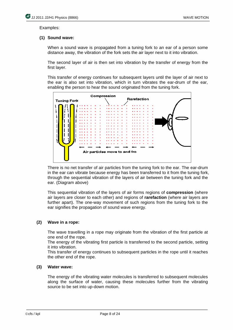
Examples: (1) Sound wave:
When a sound wave is propagated from a tuning fork to an ear of a person some distance away, the vibration of the fork sets the air layer next to it into vibration. The second layer of air is then set into vibration by the transfer of energy from the first layer. This transfer of energy continues for subsequent layers until the layer of air next to the ear is also set into vibration, which in turn vibrates the ear-drum of the ear, enabling the person to hear the sound originated from the tuning fork.
There is no net transfer of air particles from the tuning fork to the ear. The ear-drum in the ear can vibrate because energy has been transferred to it from the tuning fork, through the sequential vibration of the layers of air between the tuning fork and the ear. (Diagram above) This sequential vibration of the layers of air forms regions of compression (where air layers are closer to each other) and regions of rarefaction (where air layers are further apart). The one-way movement of such regions from the tuning fork to the ear signifies the propagation of sound wave energy.
(2) Wave in a rope:
The wave travelling in a rope may originate from the vibration of the first particle at one end of the rope. The energy of the vibrating first particle is transferred to the second particle, setting it into vibration. This transfer of energy continues to subsequent particles in the rope until it reaches the other end of the rope.
(3) Water wave:
The energy of the vibrating water molecules is transferred to subsequent molecules along the surface of water, causing these molecules further from the vibrating source to be set into up-down motion.
JJ 2011 J2/H1 Physics (8866) WAVE MOTION
©cfs / kpl Page 9 of 24
The examples (1), (2) and (3) are examples of progressive waves, where energy is transferred from one region to another region through sequential vibration of a series of linked-particles. The energy of a first vibrating particle is propagated along a series of linked-particles to another region. Sound energy is propagated from the tuning fork to the ear, energy from one end of a rope is propagated to the other end, and energy from one region of water surface next to a vibrating source is propagated to another region in the ripple tank.
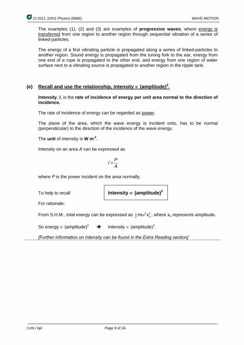
(e) Recall and use the relationship, intensity ∝ (amplitude)2.
Intensity, I, is the rate of incidence of energy per unit area normal to the direction of incidence. The rate of incidence of energy can be regarded as power. The plane of the area, which the wave energy is incident onto, has to be normal (perpendicular) to the direction of the incidence of the wave energy. The unit of intensity is W m-2. Intensity on an area A can be expressed as
I = PA
where P is the power incident on the area normally.
To help to recall Intensity ∝ (amplitude)2 For rationale: From S.H.M., total energy can be expressed as 2 21
2 om xω , where xo represents amplitude. So energy ∝ (amplitude)2 Intensity ∝ (amplitude)2. [Further information on Intensity can be found in the Extra Reading section]
JJ 2011 J2/H1 Physics (8866) WAVE MOTION
©cfs / kpl Page 10 of 24
Example 5 A sound wave of amplitude 0.20 mm has an intensity of 3.0 W m-2. What will be the intensity of a sound wave of the same frequency which has an amplitude of 0.40 mm? Solution: The relation I ∝ (amplitude)2 can be expressed as I = k(amplitude)2 where k is the constant of proportionality. Substituting, 3.0 W m-2 = k(0.20 mm)2 - - - - - (1) New intensity, I = k(0.40 mm)2 - - - - - (2) (2)(1)
: -23.= 4 I = 12.0 W m-2.
0 W mI
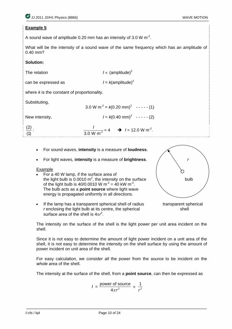
• For sound waves, intensity is a measure of loudness. • For light waves, intensity is a measure of brightness. r
Example • For a 40 W lamp, if the surface area of
the light bulb is 0.0010 m2, the intensity on the surface bulb of the light bulb is 40/0.0010 W m-2 = 40 kW m-2. The bulb acts as a point source where light wave energy is propagated uniformly in all directions.
• If the lamp has a transparent spherical shell of radius transparent spherical
r enclosing the light bulb at its centre, the spherical shell surface area of the shell is 4πr2.
The intensity on the surface of the shell is the light power per unit area incident on the shell. Since it is not easy to determine the amount of light power incident on a unit area of the shell, it is not easy to determine the intensity on the shell surface by using the amount of power incident on unit area of the shell. For easy calculation, we consider all the power from the source to be incident on the whole area of the shell. The intensity at the surface of the shell, from a point source, can then be expressed as
I = 2
power of source4 rπ
∝ 2
1r

JJ 2011 J2/H1 Physics (8866) WAVE MOTION
©cfs / kpl Page 11 of 24
Example 6 A point source of sound radiates energy uniformly in all directions. At a distance of 3.0 m from the source, the amplitude of vibration of air molecules is 1.0 × 10⁻⁷ m. Assuming that no sound energy is absorbed, calculate the amplitude of vibration 5.0 m from the source. Solution:
Using the relation above, I ∝ 2
1r
and the relation I ∝ (amplitude)2
we get the relation amplitude ∝ 1r
amplitude = cr
where c is the constant of proportionality.
Substituting, 1.0 × 10⁻⁷ m =3.0 m
c - - - - - (1)
New amplitude =5.0 m
c - - - - - (2)
(2)(1)
: 7
New amplitude 351.0 10 m− =
×
new amplitude = 6.0 × 10⁻⁸ m.
(f) Analyse and interpret graphical representations of transverse and
longitudinal waves.
In a wave, there are two directions of motions: (1) direction of propagation of energy (which is the direction of motion of the wave), (2) direction of oscillation of the particles in the wave.
JJ 2011 J2/H1 Physics (8866) WAVE MOTION
©cfs / kpl Page 12 of 24
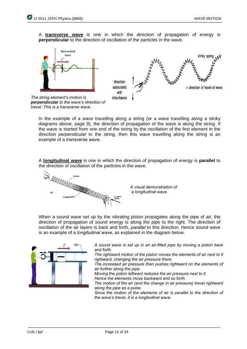
A transverse wave is one in which the direction of propagation of energy is perpendicular to the direction of oscillation of the particles in the wave. In the example of a wave travelling along a string (or a wave travelling along a slinky diagrams above, page 9), the direction of propagation of the wave is along the string. If the wave is started from one end of the string by the oscillation of the first element in the direction perpendicular to the string, then this wave travelling along the string is an example of a transverse wave. A longitudinal wave is one in which the direction of propagation of energy is parallel to the direction of oscillation of the particles in the wave.
When a sound wave set up by the vibrating piston propagates along the pipe of air, the direction of propagation of sound energy is along the pipe to the right. The direction of oscillation of the air layers is back and forth, parallel to this direction. Hence sound wave is an example of a longitudinal wave, as explained in the diagram below.
A visual demonstration of a longitudinal wave.
The string element’s motion is perpendicular to the wave’s direction of travel. This is a transverse wave.
A sound wave is set up in an air-filled pipe by moving a piston back and forth. The rightward motion of the piston moves the elements of air next to it rightward, changing the air pressure there. The increased air pressure then pushes rightward on the elements of air further along the pipe. Moving the piston leftward reduces the air pressure next to it. Hence the elements move backward and so forth. The motion of the air (and the change in air pressure) travel rightward along the pipe as a pulse. Since the motion of the elements of air is parallel to the direction of the wave’s travel, it is a longitudinal wave.

JJ 2011 J2/H1 Physics (8866) WAVE MOTION
©cfs / kpl Page 13 of 24
Graphs used to represent transverse or longitudinal waves are the same. Graph 1 : Displacement vs. Position graphs These are plotted with displacement, y, against distance or position, x.
For a transverse wave moving from left to right along the x-axis, displacement of the particles in the wave, y, may be given a +ve sign for displacement upwards, and a –ve sign for displacement downwards. For a longitudinal wave moving from left to right along the x-axis, displacement of the particles in the wave, y, may be given a +ve sign for displacement to the right, and a –ve sign for displacement to the left.
raph 2 : Displacement vs. Time graphs In contrast, graphs used to represent an oscillation of a particle are plotted with displacement, y, against time, t.
In the graph above, we are tracking the displacement of one particle only as time goes by. This does NOT represent the wave.
In Displacement vs. Position graphs, • the graph represents the actual wave
at an instant in time • the distance between consecutive
crests or consecutive troughs is one wavelength
• The maximum height of the vertical axis = amplitude of wave
distance
JJ 2011 J2/H1 Physics (8866) WAVE MOTION
©cfs / kpl Page 14 of 24
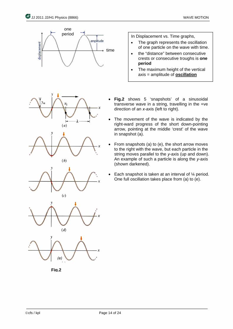
• Fig.2 shows 5 ‘snapshots’ of a sinusoidal transverse wave in a string, travelling in the +ve direction of an x-axis (left to right).
• The movement of the wave is indicated by the
right-ward progress of the short down-pointing arrow, pointing at the middle ‘crest’ of the wave in snapshot (a).
• From snapshots (a) to (e), the short arrow moves
to the right with the wave, but each particle in the string moves parallel to the y-axis (up and down). An example of such a particle is along the y-axis (shown darkened).
• Each snapshot is taken at an interval of ¼ period.
One full oscillation takes place from (a) to (e).
In Displacement vs. Time graphs, • The graph represents the oscillation
of one particle on the wave with time. • the “distance” between consecutive
crests or consecutive troughs is one period
• The maximum height of the vertical axis = amplitude of oscillation
time
one period
(e)
Fig.2
JJ 2011 J2/H1 Physics (8866) WAVE MOTION
©cfs / kpl Page 15 of 24
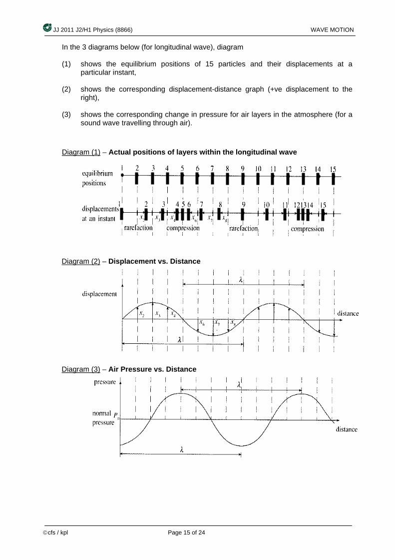
In the 3 diagrams below (for longitudinal wave), diagram (1) shows the equilibrium positions of 15 particles and their displacements at a
particular instant, (2) shows the corresponding displacement-distance graph (+ve displacement to the
right), (3) shows the corresponding change in pressure for air layers in the atmosphere (for a
sound wave travelling through air).
Diagram (1) – Actual positions of layers within the longitudinal wave
Diagram (2) – Displacement vs. Distance
Diagram (3) – Air Pressure vs. Distance
JJ 2011 J2/H1 Physics (8866) WAVE MOTION
©cfs / kpl Page 16 of 24
Summary For Part (f):
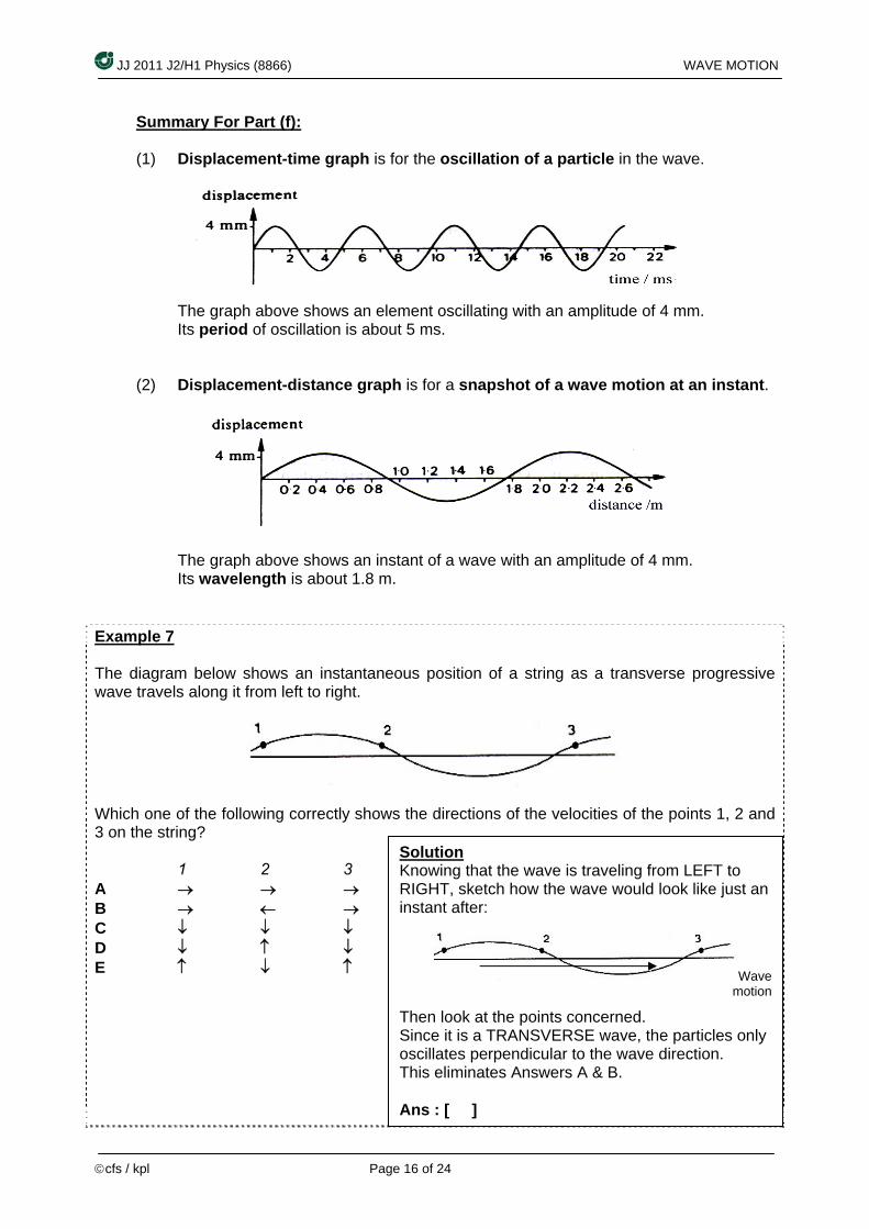
(1) Displacement-time graph is for the oscillation of a particle in the wave.
The graph above shows an element oscillating with an amplitude of 4 mm.
(2) isplacement-distance graph is for a snapshot of a wave motion at an instant.
Its period of oscillation is about 5 ms. D
The graph above shows an instant of a wave with an amplitude of 4 mm.
xample 7
Its wavelength is about 1.8 m.
E The diagram below shows an instantaneous position of a string as a transverse progressive wave travels along it from left to right.
Which one of the following correctly shows the directions of the velocities of the points 1, 2 and 3 on the string? 1 2 3 A → → → B → ← → C ↓ ↓ ↓ D ↓ ↑ ↓ E ↑ ↓ ↑
Solution at the wave is traveling from LEFT to Knowing th
RIGHT, sketch how the wave would look like just an instant after:
Wave motion
Then look at the points concerned. Since it is a TRANSVERSE wave, the particles only oscillates perpendicular to the wave direction. This eliminates Answers A & B. Ans : [ ]
JJ 2011 J2/H1 Physics (8866) WAVE MOTION
©cfs / kpl Page 17 of 24
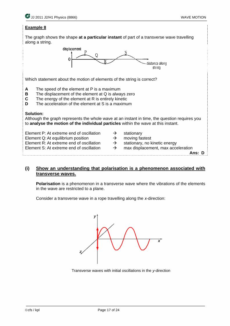
Example 8 The graph shows the shape at a particular instant of part of a transverse wave travelling along a string.
Which statement about the motion of elements of the string is correct? A The speed of the element at P is a maximum B The displacement of the element at Q is always zero C The energy of the element at R is entirely kinetic D The acceleration of the element at S is a maximum Solution: Although the graph represents the whole wave at an instant in time, the question requires you to analyse the motion of the individual particles within the wave at this instant. Element P: At extreme end of oscillation stationary Element Q: At equilibrium position moving fastest Element R: At extreme end of oscillation stationary, no kinetic energy Element S: At extreme end of oscillation max displacement, max acceleration Ans: D (i) Show an understanding that polarisation is a phenomenon associated with
transverse waves.
Polarisation is a phenomenon in a transverse wave where the vibrations of the elements in the wave are restricted to a plane. Consider a transverse wave in a rope travelling along the x-direction:
Transverse waves with initial oscillations in the y-direction
JJ 2011 J2/H1 Physics (8866) WAVE MOTION
JJ 2011 J2/H1 Physics (8866) WAVE MOTION
©cfs / kpl Page 18 of 24 ©cfs / kpl Page 18 of 24
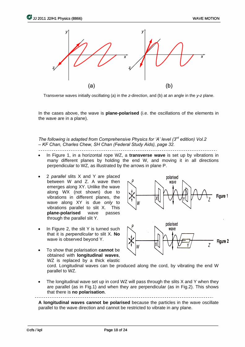
Transverse waves initially oscillating (a) in the z-direction, and (b) at an angle in the y-z plane.
i.e. the oscillations of the elements in ave are in a plane).
rehe evel (3rd edition) Vol.2 (Fe 2.
W t ns in
. Unlike the wave
through the parallel slit Y.
• In Figure 2, the slit Y is turned such that it is perpendicular to slit X. No wave is observed beyond Y.
• To show that polarisation cannot be
obtained with longitudinal waves, WZ is replaced by a thick elastic cord. Longitudinal waves can be produced along the cord, by vibrating the end W parallel to WZ.
• The longitudinal wave set up in cord WZ will pass through the slits X and Y when they
are parallel (a ig.2). This shows
A longitudinal waves cannot be polarised because the particles in the wave oscillate parallel to the wave direction and cannot be restricted to vibrate in any plane.
In the cases above, the wave is plane-polarised (the w
The following is adapted from Comp nsive Physics for ‘A’ l
Cha de– KF Chan, Charles Chew, SH n ral Study Aids), page 3
Z, • In Figure 1, in a horizontal rope a ransverse wave is set up by vibratiomany different planes by holding the end W, and moving it in all directions perpendicular to WZ, as illustrated by the arrows in plane P.
• 2 parallel slits X and Y are placed between W and Z. A wave then emerges along XYalong WX (not shown) due to vibrations in different planes, the wave along XY is due only tovibrations parallel to slit X. This plane-polarised wave passes
s in Fig.1) and when they are perpendicular (as in Fthat there is no polarisation.
JJ 2011 J2/H1 Physics (8866) WAVE MOTION
©cfs / kpl Page 19 of 24
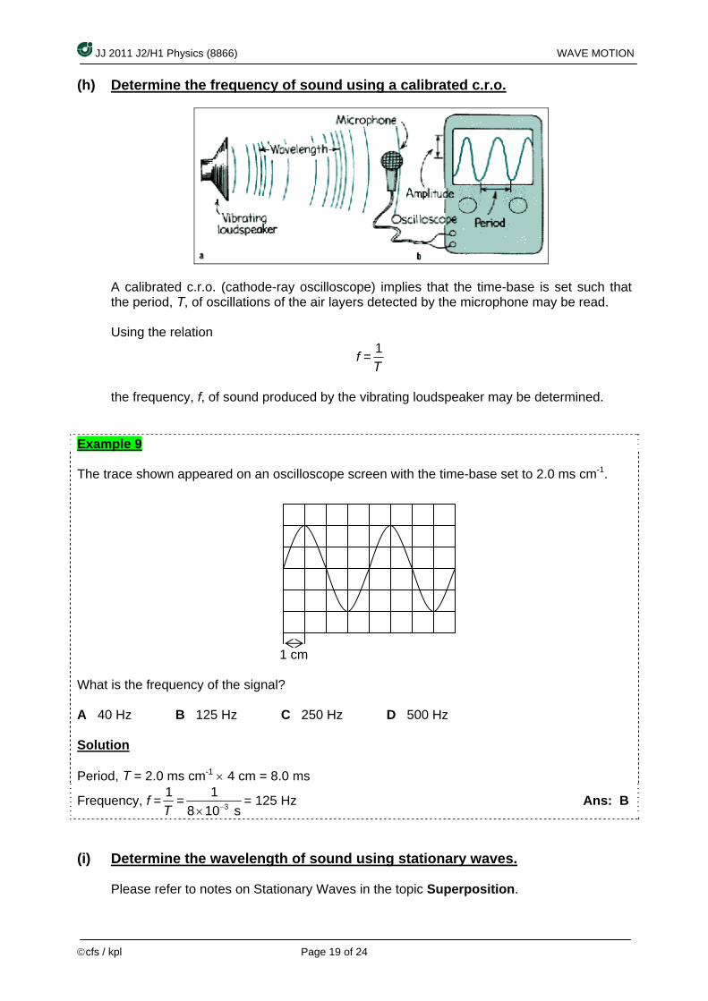
(h) Determine the frequency of sound using a calibrated c.r.o.
calibrated c.r.o. (cathode-ray oscilloscope) implies that the time-base is set such that e period, T, of oscillations of the air layers detected by the microphone may be read.
f =
Ath Using the relation
1T
the frequency, f, of sound produced by the vibrating loudspeaker may be determined.
Example 9 The trace shown appeared on an oscilloscope screen with the time-base set to 2.0 ms cm-1. 1 cm What is the frequency of the signal? A 40 Hz B 125 Hz C 250 Hz D 500 Hz Solution Period, T = 2.0 ms cm-1 × 4 cm = 8.0 ms
Frequency, f = 1T
= 38 10 s−×= 125 Hz Ans: B 1
) Determine the wavelength of sound using stationary waves.(i
Please refer to notes on Stationary Waves in the topic Superposition.

JJ 2011 J2/H1 Physics (8866) WAVE MOTION
©cfs / kpl Page 20 of 24
Extra Reading
Electromagnetic Waves James Clerk Maxwell’s (1831 – 1879) crowning achievement was to show that a beam of light is a travelling wave of electric and magnetic field, an electro-magnetic wave. In Maxwell’s time, the visible, infrared and ultraviolet form of light were the only electromagnetic waves known. Heinrich Hertz then discovered what we now call radio waves and verified that they move through the laboratory at the same speed as visible light. We now know a wide spectrum of electromagnetic waves. The Sun, being the dominant source of these waves, continually bathes us with electromagnetic waves throughout this spectrum.
Type of EM wave Typical Wavelengths λ and its
corresponding frequency, f. Orders of magnitude for wavelength, λ / m
Gamma (γ) rays λ = 1 pm = 10-12 m f = 3 x 10²⁰ Hz 10-12
x-rays λ = 100 pm = 10-10 m f = 3 x 10¹⁸ Hz 10-10
UV ultraviolet λ = 10 nm = 10-8 m f = 3 x 10¹⁶ Hz 10-8
Visible light red
λgreen = 600 nm = 0.6 μmλ = 700 nm
λviolet = 400 nm fgreen = 5 x 10¹⁴ Hz
10-6
IR (infra-red) = f λ 100 μm = 10-4 m
= 3 x 10¹² Hz 10-4
Radio wavemicrowaves, )
λ f =
(includes UHF, VHF etc
= 3 m 108 Hz 100 ~ 10-2
Properties of Electromagnetic Waves
) EM waves consist of oscillating electric and magnetic fields that are perpendicular to
) EM waves are all transverse waves.
1) EM waves have the same speed, c, in vacuum (c ≈ 3 x 10⁸ m s-1). 2
each other. 3

JJ 2011 J2/H1 Physics (8866) WAVE MOTION
©cfs / kpl Page 21 of 24
Extra Reading Energy (E) and Intensity (I) of a Progressive Wave
rgy and elastic otential energy.
imple harmonic motion as the wave passes through it, has KE
When we set up a wave on a stretched string, we provide energy for the motion of the string. As the wave moves away from us, it transports that energy as both kinetic enep Kinetic Energy An element of the string of mass Δm, oscillating transversely in sassociated with its transverse velocity u . • When the element is rushing through its y = 0 position
(element b in the diagram), its transverse velocity – and thus its KE - is a maximum.
• When the element is at its extreme position y = A (element a), its transverse velocity – and thus its KE – is zero.
Elastic Potential Energy To send a sinusoidal wave along a previously straight string, the wave must necessarily stretch the string. As a string element of length Δx oscillates transversely , its length must increase and decrease in a periodic way if the string element is to fit the sinusoidal waveform. Elastic potential energy is associated with these length changes, just as for a spring. • When the string element is at y = A, its length has its normal undisturbed value Δx, so its
elastic potential energy is zero. • However, when the element is rushing through its y = 0 position, it is stretched to its
maximum extent, and its elastic potential energy then is a maximum. Energy Transmitted As waves travel through a medium, energy is transmitted as vibrational energy from particle to article of the medium. The energy, E, is given by:
= f itude
Si I f2A2. For a given source of fixed vibrations is co a
∴ where A = amplitude The unit for Intensity, I, is W m-2.
p
E ∝ f2A2, where f requency, and A = ampl
nce E ∝ f2A2 ⇒ Intensity, ∝
, f nst nt.
I ∝ A2
JJ 2011 J2/H1 Physics (8866) WAVE MOTION
©cfs / kpl Page 22 of 24
Extra Reading Polarisation of light
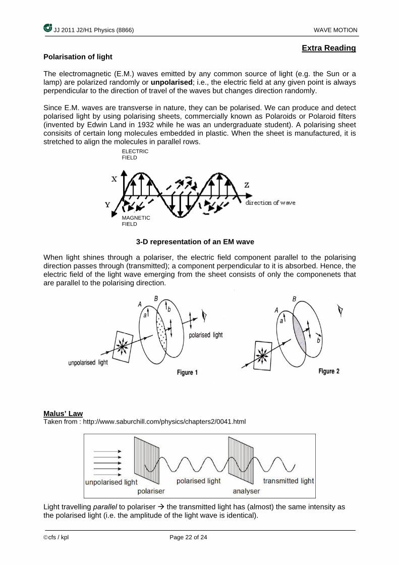
he electromagnetic (E.M.) waves emitted by any common source of light (e.g. the Sun or a s
ince E.M. waves are transverse in nature, they can be polarised. We can produce and detect using polarising sheets, commercially known as Polaroids or Polaroid filters
ate student). A polarising sheet the sheet is manufactured, it is
l ows.
ng ); a component perpendicular to it is absorbed. Hence, the
ts that
Tlamp) are polarized randomly or unpolarised; i.e., the electric field at any given point is alwayperpendicular to the direction of travel of the waves but changes direction randomly. Spolarised light by(invented by Edwin Land in 1932 while he was an undergraduconsisits of certain long molecules embedded in plastic. When stretched to align the molecules in para lel r
When light shines through a polariser, the electric field component parallel to the polarisidirection passes through (transmittedelectric field of the light wave emerging from the sheet consists of only the componeneare parallel to the polarising direction.
Malus’ Law
burchill.com/physics/chapters2/0041.html Taken from : http://www.sa
Light travelling parallel to polariser the transmitted light has (almost) the same intensity as the polarised light (i.e. the amplitude of the light wave is identical).
MAGNETIC FIELD
ELECTRIC FIELD
3-D representation of an EM wave

JJ 2011 J2/H1 Physics (8866) WAVE MOTION
©cfs / kpl Page 23 of 24
When the 2nd polariser, or the Analyser is perpendicular to polariser, no transmitted light is observed. Hence, intensity is zero. (i.e. the amplitude of the light wave is zero).
With the polariser and analyser at some other angle, θ, the amplitude of the transmitted light waves is equal to component of the amplitude of the polarised light parallel to the plane of the analyser.
amplitude squared, we conclude that if polarised light is incident on a polarising filter, the intensity of the transmitted light is proportional to the cos2 of the angle between the plane of polarisation and the plane of the filter:
Therefore, amplitude of transmitted light is given by
(amplitude of polarised light) × cos θ Since intensity of a wave is proportional to its
20 costransmittedI I θ=
where I0 is the intensity of the light incident on the analyser and I is the intensity of the transmitted light.
This is called Malus’ law.
ses of Polarisers : LCD panels
U
s, a bright white light is emitted behind the panels. This source of light is typically a use LEDs to illuminate the
anels leading to better energy efficiency.
Liquid crystals are the 4th state of matter, with plasma being the 5th state. Liquid crystal is a liquid substance that has solid-like properties, often rod-shaped and their orientation can be changed using electric fields. The LCD panels is made from 2 polarizer with axis aligned 90° apart. Between these polarizer are 2 layers of glass panel, with an “invisible electrode” etched on each side. The electrodes are typically made of indium-tin-oxide, a transparent and conductive material. The liquid crystal is placed between these 2 glass panels, but their orientation gradually twists till they are 90° apart, each orientation corresponding to the
In LCD panelfluorescent backlight. In recent years, there has been a move top
polarizer’s axis nearest to them.

JJ 2011 J2/H1 Physics (8866) WAVE MOTION
©cfs / kpl Page 24 of 24
Diagram taken from : http://qxwujoey.tripod.com/lcd.htm
n travels crystals. The crystals change the plane of polarization, allowing light to be
nd polarizer. An observer will hence see that the screen is “bright” or
hen an electric field is applied across the liquid crystal, their crystal orientation is now traightened. Light passing the 1st polarizer will hence travel along the liquid crystal but cannot
90° to it. An observer will observe the screen as “dark” or
White light passing through the 1st polarizer will be polarized in one direction, which thethrough the liquid able to pass through the 2“white”.
Wspass through the 2nd polarizer as it is“black”. By controlling the electric field over very tiny areas (called pixels), light can be filtered out or allowed to pass through, creating an image on the screen.