Embed Size (px)
Citation preview
user manual
80 gallon vertrical air compressor
2 3
table of contents
Introduction4 Using the Operator’s Manual
Product Identification5 Record Identification Numbers
Safety6 Safety Precautions and Warnings
Troubleshooting7 Troubleshooting Chart
Compressor Maintenance10 Maintenance11 Storage
Adjustments & Alignment12 Adjusting Belt Tension12 Pulley Alignment
Description of Compressor13 What is a reciprocating compressor?13 Description of Cooling13 Description of Controls
Pre-Operation14 Receiving and uncrating of your compressor14 Compressor Installation14 Location14 Mounting15 Induction System15 Noise15 Piping Fitup16 Safety Valves16 Pressure Vessels16 Electrical17 Pressure Switch17 Manual Relief and Shutoff Valves17 Guards18 Drive
table of contents
Installation19 Installation Diagram
Start Up Preparation20 Start Up Preparation
Maintenance21 Stopping for Maintenance or Service22 Daily22 Weekly22 Monthly22 Every 3 Months23 Storage of Compressor
Parts Breakdown24 CA1 and CA1U

4 5
Using the Operator’s manualThe operating manual is an important part of your Compressor. It should be read thoroughly before initial use, and referred to often to make sure adequate safety and service concerns are being addressed.
Reading the owner’s manual thoroughly will help avoid any personal injury or damage to your pump. By knowing how best to operate this machine you will be better positioned to show others who may also operate the unit.
You can refer back to the manual at any time to help troubleshoot any specific operating functions, so store it with the machine at all times.
Attention: Read through the complete manual prior to the initial use of your Compressor
introduction product identification
Record Identification Numbers
COMPRESSORIf you need to contact an Authorized Dealer or Customer Service line (1-855-850-6668) for information on servicing, always provide the product model and identification numbers.
You will need to locate the model and serial number for the pump and record the information in the places provided below.
Date of Purchase:
Dealer Name:
Dealer Phone:
Product Identification Numbers
Model Number:
Serial Number:
6 7
safety
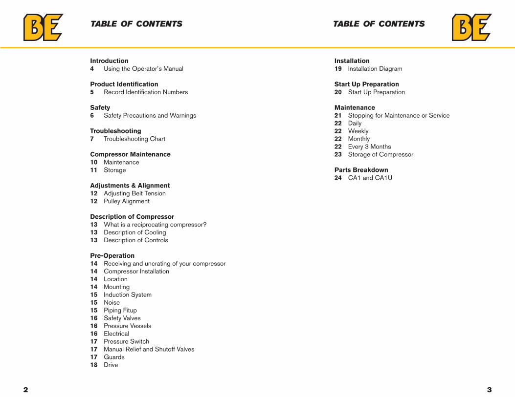
Safety Precautions and WarningsListed are some, but not all safety precautions that must be observed with compressors. Failure to follow any of these warnings may result in severe personal injury, death, property damage and/or compressor damage.
• Air from this compressor will cause severe injury or death if used for breathing or food processing.
• Air used for these processes must meet OSHA 29 CFR 1910 or FDA 21 178.3570 regulations.
• This compressor is designed for use in the compression of normal atmospheric air only. No other gases, vapors or fumes should be exposed to the compressor intake, nor processed through the compressor.
• Disconnect all power supplies to the compressor plus any remote controllers prior to servicing the unit.
• Relieve all pressure internal to the compressor prior to servicing.• Do not depend on check valves to hold system pressure.• A properly sized safety valve must be installed in the discharge piping
ahead (upstream) of any shutoff valve (block valve), heat exchanger, orifice or any potential blockage point. Failure to install a safety relief valve could result in rupturing or explosion of some compressor or safety component.
• Do not change the pressure setting of the safety relief valve, restrict the function of the safety relief valve, or replace the safety valve with a plug.
• Over pressurization of some system or compressor component can occur, resulting in severe personal injury, death and property damage.
• Never use plastic pipe, rubber hose, or soldered joints in any part of the compressors. Failure to ensure system compatibility with compressor piping is dangerously unsound.
• Never use a flammable or toxic solvent for cleaning the air filter or any other components.
• Do not attempt to service any part while the compressor is operating.• Do not operate the compressor at pressures in excess of its rating.• Do not remove any guards while the compressor is operating.• Observe gauges daily to ensure compressor is operating properly.• Follow all maintenance procedures and check all safety devices on
schedule.• Compressed air is dangerous, do not play with it.• Use the correct lubricant at all times.
troubleshooting
Troubleshooting ChartNOTE: Troubleshooting problems may have similar causes and solutions.
Problem Possible Cause SolutionsBreaker Trips 1. Low Voltage supply
2. Motor overloads tripped3. Restricted air passages4. Loose wires at contact points5. Seized Pump
1. Check that incomingpower wire size is adequate forcompressor2. Check that compressor is ondedicated circuit3. Adjust belt tension4. Check wire connections tomake sure they are tight5. Inspect transfer tubes and,check valve
Compressor stalls
1. Low voltage supply tocompressor2. Loose compressor belts3. Bad check valve4. Seized compressor pump
1. Check compressor powersupply for adequate breaker andwire size2. Inspect check valve for properoperation3. Tighten belts4. Check compressor for properoil level.
Low Discharge Pressure
1. Air leaks in shop2. Leaking valves3. Restricted air intake4. Blown gaskets/seals5. Worn piston rings or cylinder
1. Tighten or replace leakingfittings, or joints2. Clean or replace air filter
Compressor pump knocking
1. Loose motor pulley orcompressor flywheel.
2. Low oil level in compressorpump.
3. Carbon build up on valve and piston.
1. Tighten pulley or flywheel.
2. Keep oil level at recommendedlevel for proper operation.
3. Only use factory recommendedoil.
WARNINGALWAYS MAKE SURE ELECTRICAL POWER IS OFF BEFORE REMOVING ANY INSPECTION COVERS OR PLATES.You should always contact an authorized service center before attempting to fix or repair your air compressor
8 9
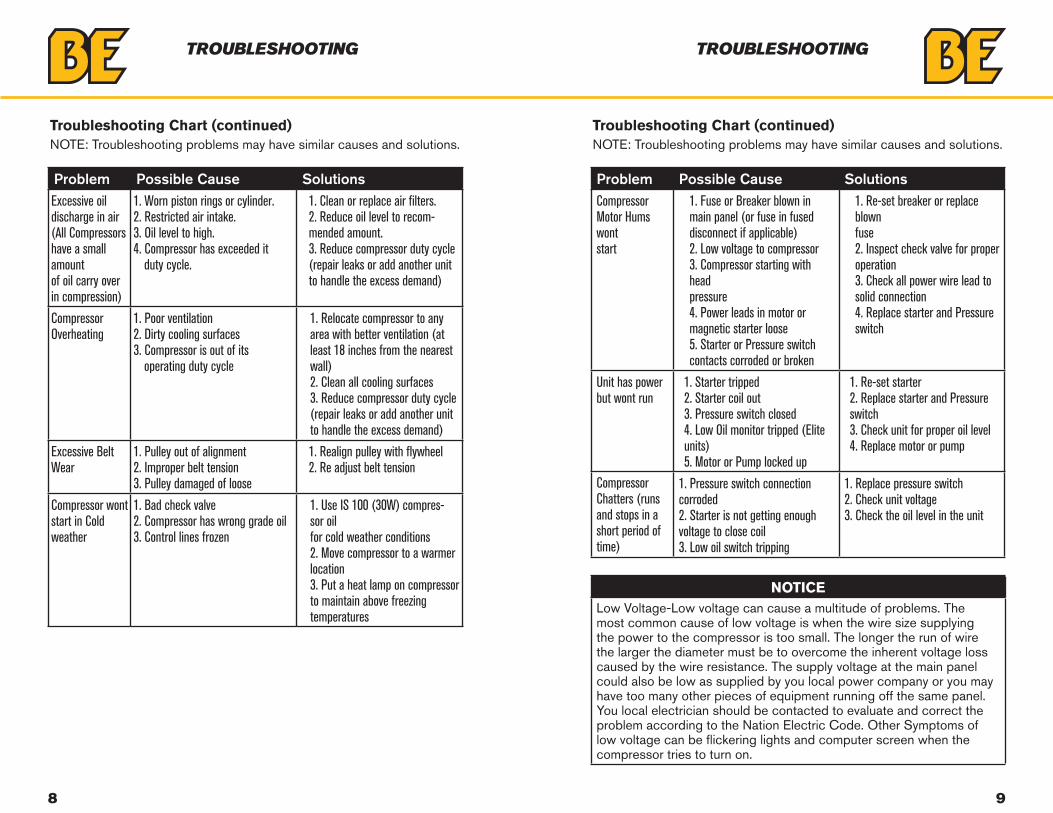
Problem Possible Cause SolutionsExcessive oil discharge in air (All Compressors have a small amountof oil carry over in compression)
1. Worn piston rings or cylinder.2. Restricted air intake.3. Oil level to high.4. Compressor has exceeded it
duty cycle.
1. Clean or replace air filters.2. Reduce oil level to recom-mended amount.3. Reduce compressor duty cycle(repair leaks or add another unitto handle the excess demand)
Compressor Overheating
1. Poor ventilation2. Dirty cooling surfaces3. Compressor is out of its
operating duty cycle
1. Relocate compressor to anyarea with better ventilation (atleast 18 inches from the nearestwall)2. Clean all cooling surfaces3. Reduce compressor duty cycle(repair leaks or add another unitto handle the excess demand)
Excessive Belt Wear
1. Pulley out of alignment2. Improper belt tension3. Pulley damaged of loose
1. Realign pulley with flywheel2. Re adjust belt tension
Compressor wont start in Coldweather
1. Bad check valve2. Compressor has wrong grade oil3. Control lines frozen
1. Use IS 100 (30W) compres-sor oilfor cold weather conditions2. Move compressor to a warmerlocation3. Put a heat lamp on compressorto maintain above freezingtemperatures
troubleshooting
Troubleshooting Chart (continued)NOTE: Troubleshooting problems may have similar causes and solutions.
Troubleshooting Chart (continued)NOTE: Troubleshooting problems may have similar causes and solutions.
troubleshooting
Problem Possible Cause SolutionsCompressor Motor Hums wontstart
1. Fuse or Breaker blown inmain panel (or fuse in fuseddisconnect if applicable)2. Low voltage to compressor3. Compressor starting with headpressure4. Power leads in motor ormagnetic starter loose5. Starter or Pressure switchcontacts corroded or broken
1. Re-set breaker or replace blownfuse2. Inspect check valve for properoperation3. Check all power wire lead tosolid connection4. Replace starter and Pressureswitch
Unit has power but wont run
1. Starter tripped2. Starter coil out3. Pressure switch closed4. Low Oil monitor tripped (Eliteunits)5. Motor or Pump locked up
1. Re-set starter2. Replace starter and Pressureswitch3. Check unit for proper oil level4. Replace motor or pump
Compressor Chatters (runs and stops in a short period of time)
1. Pressure switch connectioncorroded2. Starter is not getting enoughvoltage to close coil3. Low oil switch tripping
1. Replace pressure switch2. Check unit voltage3. Check the oil level in the unit
NOTICELow Voltage-Low voltage can cause a multitude of problems. The most common cause of low voltage is when the wire size supplying the power to the compressor is too small. The longer the run of wire the larger the diameter must be to overcome the inherent voltage loss caused by the wire resistance. The supply voltage at the main panel could also be low as supplied by you local power company or you may have too many other pieces of equipment running off the same panel. You local electrician should be contacted to evaluate and correct the problem according to the Nation Electric Code. Other Symptoms of low voltage can be flickering lights and computer screen when the compressor tries to turn on.
10 11
compressor maintenance
Daily:Drain the Receiver- condensation will accumulate in the tank every day, so it should be drained at least once a day. Doing this will help reduce the possibility of corrosion inside the tank. Always wear protective eye wear when draining the tank. Check Pump Oil Level - All units have a sight glass to gauge the oil level.Non running units should be no lower than ½ way on the sight glass if it is lower then you need to add oil until it is at least ½ way up the sight glass.Check unit for any unusual noise or vibrations.
Weekly:
Clean air filter to ensure that no dirt or heavy particulate makes its way into the compressors valve assemblies.Clean external parts of compressor and electric motor, this helps to ensure proper cooling and prevents rust and corrosion on critical parts.Check safety valves to ensure they are not stuck in place and are operating properly.Elite units Check auto tank drain for proper function.
Monthly:
Inspect complete air system for leaks to make sure the compressor does not get out of its duty cycle due to air leak in the system.
Inspect oil for contamination to ensure that harmful deposits do not build up in the oil.
Check belt tension, to ensure the belts do not fail pre-maturely. Tighten them as needed to ensure they do not slip. If belts are loose, tighten per instructions on next page. Failure to tighten can cause pre-mature belt failure.
Every 3 months:Change oil to ensure that the compressor has proper oil level and that the oil in the machine does not deteriorate past factory specifications.Inspect valve assemblies to prevent premature failure and clean out and carbon that can form in older valves.
WARNINGTo avoid personal injury, always shut OFF the main power supply and disconnects to the compressor, relive all air pressure from the sys-tem, and check electrical system with electrical probe before starting any service or maintenance on the compressor.
*Elite units clean auto tank drain strainer and check for proper function.Inspect pressure switch for proper function.Inspect check valve for proper function and remove any carbon accumu-lation to prevent premature failure.*Clean belt guard coolers (if equipped).
Storage of Compressor:Before storing the compressor for a prolonged period of time, use a blow gun to clean all debris from compressor. Shut OFF main power and turn OFF disconnect. Drain tank pressure, clean air filter, drain old oil and replace with new oil. Cover the unit to prevent dust and moisture from collecting on the unit.
storage
12 13
adjustments & alignment
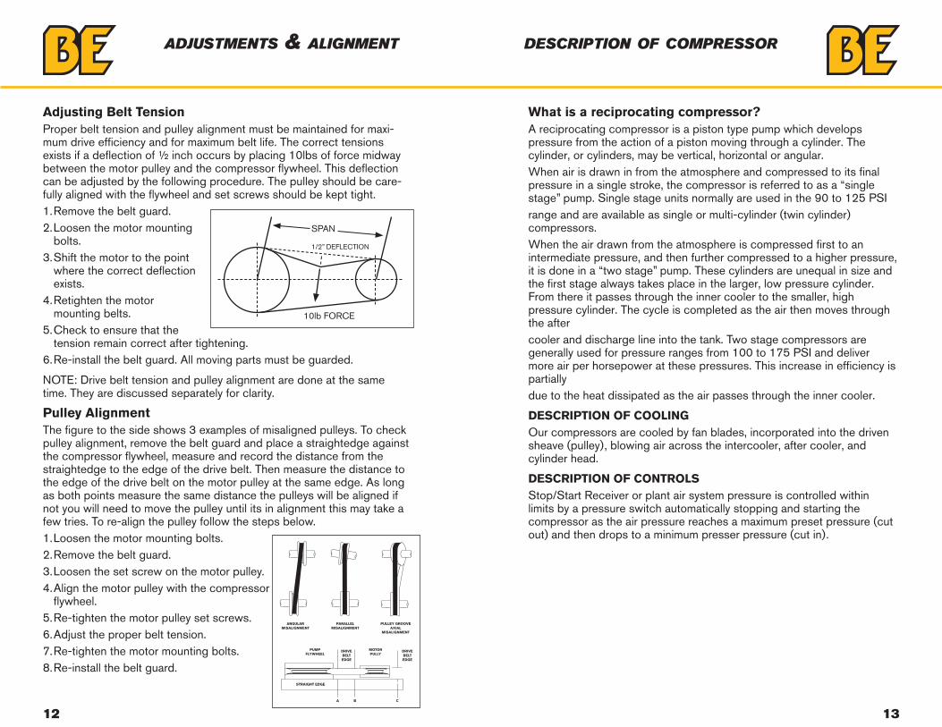
Adjusting Belt TensionProper belt tension and pulley alignment must be maintained for maxi-mum drive efficiency and for maximum belt life. The correct tensions exists if a deflection of ½ inch occurs by placing 10lbs of force midway between the motor pulley and the compressor flywheel. This deflection can be adjusted by the following procedure. The pulley should be care-fully aligned with the flywheel and set screws should be kept tight.1. Remove the belt guard.2. Loosen the motor mounting
bolts.3. Shift the motor to the point
where the correct deflection exists.
4. Retighten the motor mounting belts.
5. Check to ensure that the tension remain correct after tightening.
6. Re-install the belt guard. All moving parts must be guarded.
NOTE: Drive belt tension and pulley alignment are done at the same time. They are discussed separately for clarity.
Pulley AlignmentThe figure to the side shows 3 examples of misaligned pulleys. To check pulley alignment, remove the belt guard and place a straightedge against the compressor flywheel, measure and record the distance from the straightedge to the edge of the drive belt. Then measure the distance to the edge of the drive belt on the motor pulley at the same edge. As long as both points measure the same distance the pulleys will be aligned if not you will need to move the pulley until its in alignment this may take a few tries. To re-align the pulley follow the steps below.1. Loosen the motor mounting bolts.2. Remove the belt guard.3. Loosen the set screw on the motor pulley.4. Align the motor pulley with the compressor
flywheel.5. Re-tighten the motor pulley set screws.6. Adjust the proper belt tension.7. Re-tighten the motor mounting bolts.8. Re-install the belt guard.
ANGULARMISALIGNMENT
PARALLELMISALIGNMENT
PULLEY GROOVEAXIAL
MISALIGNMENT
PUMPFLYWHEEL
STRAIGHT EDGE
MOTORPULLY
DRIVEBELTEDGE
DRIVEBELTEDGE
A B C
What is a reciprocating compressor?A reciprocating compressor is a piston type pump which develops pressure from the action of a piston moving through a cylinder. The cylinder, or cylinders, may be vertical, horizontal or angular.When air is drawn in from the atmosphere and compressed to its final pressure in a single stroke, the compressor is referred to as a “single stage” pump. Single stage units normally are used in the 90 to 125 PSIrange and are available as single or multi-cylinder (twin cylinder) compressors.When the air drawn from the atmosphere is compressed first to an intermediate pressure, and then further compressed to a higher pressure, it is done in a “two stage” pump. These cylinders are unequal in size and the first stage always takes place in the larger, low pressure cylinder. From there it passes through the inner cooler to the smaller, high pressure cylinder. The cycle is completed as the air then moves through the aftercooler and discharge line into the tank. Two stage compressors are generally used for pressure ranges from 100 to 175 PSI and deliver more air per horsepower at these pressures. This increase in efficiency is partiallydue to the heat dissipated as the air passes through the inner cooler.
DESCRIPTION OF COOLINGOur compressors are cooled by fan blades, incorporated into the driven sheave (pulley), blowing air across the intercooler, after cooler, and cylinder head.
DESCRIPTION OF CONTROLSStop/Start Receiver or plant air system pressure is controlled within limits by a pressure switch automatically stopping and starting the compressor as the air pressure reaches a maximum preset pressure (cut out) and then drops to a minimum presser pressure (cut in).
description of compressor
14 15
RECEIVING AND UNCRATING OF YOUR COMPRESSOR
Before uncrating the compressor the following steps should be taken.1. Immediately upon receipt of the equipment, it should be inspected
for damage that may have occurred during shipment. If any damage is found, demand an inspection immediately by an inspector from the carrier. Ask him how to file a claim for damages. (See Appendix “A” for Details).
2. Insure that adequate lifting equipment is available for moving the machinery.
3. Read the compressor nameplate to be sure the compressor is the model and size ordered.
4. Read the motor nameplate to be sure the motor is compatible with your electrical conditions. (Volts-Phase-Hertz).
Compressor Installation
LOCATIONPlace the compressor in an indoor area that is clean, dry, well lighted, and well ventilated, with sufficient space for safe and proper inspection and maintenance. Ambient temperatures should not exceed 104 degrees F or fall below 30 degrees unless an electric motor rated for a higher tem-perature is used. Inspection and maintenance checks are required daily, therefore, ample space is required around the compressor.The compressor must not be installed closer than fifteen inches from a wall or from another compressor to allow ample circulation or air across the compressor cylinders and head, and through the coolers if they are part of the system. Additional safety can be achieved by locating the pulley guard next to the wall.
pre-operation
WARNINGImproper lifting can result in component or system damage or personal injury. Follow good shop practices and safety procedures.
NOTICEStandard motors are open drip proof with a maximum ambient temperature rating of 104 degrees F. They are not suitable for salt laden, corrosive, dirty, wet, or explosive environments.
MOUNTINGWe recommend the use of rubber pads or isolators between the tank legs and the floor. If a shim is required to level the unit, place it between the pad and floor. If you bolt the unit to the floor, use the bolts as guide pins and do not tighten the bolts. The rubber pads are used to absorb machine vibration and cannot work effectively if bolted tightly.
INDUCTION SYSTEMDo not locate the compressor where it could ingest or ignite toxic, explosive or corrosive vapors, ambient air temperatures exceeding 104 degrees F, water or extremely dirty air. Ingestion of any of the above noted atmospheres by the compressor could jeopardize the performance of the equipment and all personnel exposed to the total compressor.Depending on the size of the compressor and the size and construction of the compressor room it may be necessary to locate the air pickup point outside the room. Destructive pulsations can be induced by reciprocating compressors that will damage walls and break windows. Pulsation can be minimized by adding a pulsation dampener on the inlet side of the compressor.
pre-operation
NOISENoise is a potential health hazard that must be considered. There are local and federal laws specifying maximum acceptable noise levels that must not be exceeded. Most of the noise from a reciprocating compressor originates from the air inlet point. Excessive noise can be greatly reduced by installing an intake noise silencer
PIPING FITUPCare must be taken to avoid assembling the piping in a strain with the compressor. It should line up without having to spring or twist into posi-tion. Adequate expansion loops or bends should be installed to prevent undue stresses at the compressor resulting from the changes between hot and cold conditions. Pipe support should be mounted independently of the compressor and anchored as necessary to limit vibration and pre-vent expansion strains.
CAUTIONUnder no circumstances should a compressor be placed in an area that may be exposed to a toxic, volatile or corrosive atmosphere nor should toxic, volatile or corrosive agents be stored near the compressor.
16 17
pre-operation
PRESSURE VESSELSAir receiver tanks and other pressure containing vessels such as, but not limited to, pulsation bottles, heat exchangers, moisture separators and traps, shall be in accordance with ASME Boiler and Pressure Vessel Code Section VIII and ANSI B19.3 Safety Standards.
CAUTIONASME coded pressure vessels must not be modified, welded, repaired, reworded or subjected to operation conditions outside the nameplate ratings. Such actions will negate code status, affect insurance status and may cause severe personal injury, death, and property damage.
CAUTIONThe installation, wiring, and all electrical controls must be in ac-cordance with ANSI C1 National Electric Code, ANSE C2 National Electric Safety Code, state and local codes. All electrical work should be performed by a qualified electrician. Failure to abide by the national, state and local codes may result in physical and/or property damage.
DANGERFailure to properly size, set & install pressure relief valves can be fatal.
SAFETY VALVES Safety valves are pressure relief valves and should be sized and purchased with a pressure setting to protect the weakest link in the system. Never change the pressure setting, only the safety valve manufacturer is qualified to make a change. Safety valves are to be place ahead of any potential blockage point which included but is not limited to, shutoff valves, heat exchangers, pulsation dampeners, and discharge silencers.
DANGERSafety valves are to protect system integrity in accordance with ASME Codes and ANSI B19.3 safety standards. Failure to use safety valves of the proper capacity and pressure will cause severe personal injury or death.
NOTICEStandard motors are open drip proof with a maximum ambient temperature rating of 104 degrees F. They are not suitable for salt laden, corrosive, dirty, wet, or explosive environments.
PRESSURE SWITCHThe pressure switch is automatic in operation and is adjusted to start and stop the unit at the minimum and maximum desired air receiver pressure by cutting in and out the power to the electric motor. On some models, the pressure switch incorporates a release valve, which releases air between the check valve located in the receiver and discharge valve in the head of the compressor.
ELECTRICALBefore installation, the electrical supply should be checked for adequate wire size and transformer capacity. During installation a suitable fused or circuit breaker disconnect switch should be provided. Where a 3 phase motor is used to drive a compressor, any unreasonable voltage unbal-ance between the legs must be eliminated and any low voltage corrected to prevent excessive current draw. Compressors must be equipped with a properly wired magnetic motor starter or a pressure switch rated to carry the full motor current load. The coil which engages and disengages the contact points in the motor starter is controlled by the pressure switch. Never attempt to bypass the pressure switch or adjust it past the factory set pressure range. Improper installation of the electrical system can cause the motor to overheat or a short circuit to occur.
CAUTIONElectric power always exists inside the pressure switch when there is electric power at the compressor package. Either a qualified electrician should make the pressure adjustments or the electric power supply should be disconnected and locked out before making any adjustment. NEVER exceed the designed pressure for the system or overload the motor beyond its service factor. FAILURE TO HEED THESE WARN-INGS MAY RESULT IN SERIOUS INJURY OR DEATH, PROPERTY DAMAGE AND/OR MECHANICAL FAILURE
pre-operation
CAUTIONRelieve compressor and system air pressure by opening the appropri-ate manual relief valve prior to servicing. Failure to relieve all system pressure may result in severe personal injury, death & property damage.
GUARDS
All mechanical action or motion is hazardous in varying degrees and needs to be guarded. Guarding shall be in compliance with OSHA Safety and Health Standards 29 CFR 1910.219 in OSHA manual 2206 and any state or local code.
18 19
CAUTIONExcessive speed of the compressor or driver can be lethal. Never operate the compressor beyond the manufacturer’s recommendation. Bursting of the flywheel may be the greatest threat because the normal guard may not contain all the pieces. Crankshaft and connecting rod breakage is a possibility and compressor efficiency, valve life and bear-ing life will be abnormally reduced.
CAUTIONRemoval or painting over safety labels will result in uninformed conditions. This may result in personal injury or property damage. Warnings signs and labels shall be provided with enough light to read, conspicuously located and maintained for legibility. Do not remove any warning, caution, or instructional material attached! Provisions should be made to have the instruction manual readily available to the operator and maintenance personnel. If for any reason any part of the manual becomes illegible or if the manual is lost, have it replaced immediately. The instruction manual should be periodically read to refresh one’s memory, it may prevent a serious or fatal accident.
DRIVESIIt is important that the compressor and motor pulleys are aligned prop-erly and the V belt is correctly tensioned. Improper pulley alignment and belt tension are causes for motor overloading, excessive vibration, and premature belt and/or bearing failure.
pre-operation
MANUAL RELIEF AND SHUTOFF VALVESInstall a manual relief valve to vent the compressor to atmosphere. In those instances where the air receiver tank services a single compressor, the manual relief valve can be installed on the receiver. When a manual shut- off valve, and a safety relief valve installed upstream from the manual relief valve. These valves are to be designed and installed as to permit maintenance to be performed in a safe manner. Never substitute a check valve for a manual shut-off valve (block valve) if the purpose is to isolate the compressor from a system for servicing.
CAUTIONGuards must be fastened in place before starting the compressor and never removed before cutting off & locking out the main power supply.
installation
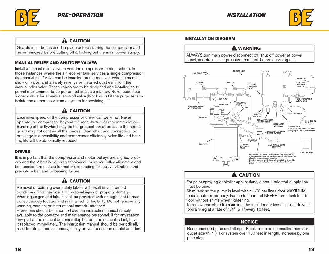
INSTALLATION DIAGRAM
NOTICERecommended pipe and fittings: Black iron pipe no smaller than tank outlet size (NPT). For system over 100 feet in length, increase by one pipe size.
CAUTIONFor paint spraying or similar applications, a non-lubricated supply line must be used.Shim tank so the pump is level within 1/8” per lineal foot MAXIMUM to distribute oil properly. Fasten to floor and NEVER force tank feet to floor without shims when tightening.To remove moisture from air line, the main feeder line must run downhill to drain-leg at a rate of 1/4” tp 1” every 10 feet.
WARNINGALWAYS turn main power disconnect off, shut off power at power panel, and drain all air pressure from tank before servicing unit.
QUICK COUPLER
AIR HOSE TOAIR TOOL
NON-LUBRICATEDSUPPLY LINE
DRAIN LEG
FEEDER LINE
BYPASS BYPASS1/4 TURNSHUT-OFFVALVE
1/4 TURNSHUT-OFFVALVE
MAGNETIC STARTER: Those not factory mounted onthe compressor can be mounted on the wall. Mount asclose to compressor as possible.Sire the wires, protect them with conduit, and providebranch circuit protection per the National ElectricalCode.
LINE FILTER
AIR-FLOW
AIR DRYER and/orAF TERCOOLER MOTOR
PUMP
RECEIVER
FLEXIBLEAIR-LINE
MAGNETIC STARTERRESET SWITCH
REGULATORwith gauge LUBRICATOR
CAUTION: NEVER use for paintspraying or similar applications.
AIR/WATER FILTERwith PETCOCK
DRIP-TEEwith drain
MAIN DISCONNECT(ON/OFF)
POWER PANEL
PRESSURESWITCH
MOISTURE TRAP WITHDRAIN
AIR-FLOW
20 21
The following check list shall be adhered to before putting the compres-sor into operation.
FAILURE TO PERFORM THESE CHECKS MAY RESULT IN SERIOUS
INJURY OR DEATH, PROPERTY DAMAGE AND/OR MECHANICAL
FAILURE. DISCONNECT AND LOCK OUT POWER SUPPLY.
1. Remove all loose pieces and tools around the compressor installation.2. Check oil level in crankcase, add as necessary.3. Check all pressure connections for tightness and leaks.4. Check to make sure all safety relief valves are in place and operational.5. Check to be sure all guards are in place and securely mounted.6. Check fuses, circuit breakers and thermal overloads for proper size.7. Open all manual shut-off valves (block valves) at and beyond the
compressor discharge.8. On all 3 phase units, after all of the above conditions have been
satisfied, jog the starter switch button to check the rotational direction of the compressor. It should agree with the rotation arrow on the flywheel/pulley (counter clockwise, facing the shaft).
The following procedures should be followed for start-up of a new installation, or after changes have been made to an existing installation, and/or after service repair work has been performed.
1. Instructions in addition to those contained within this manual, supplied by manufacturers of supporting equipment, must also be read and understood before start-up.
2. Check oil level in crankcase.3. Drain moisture from air receiver and traps.4. Start compressor and watch for excessive vibration or strange noises.
If either is observed, stop the compressor immediately and correct.5. Check air receiver or system pressure.6. Manually activated safety relief valves by pulling ring or lever.7. Check operation of controls.8. After two days of operation check belt tension, air piping for leaks, and
crankcase oil level.
start up preparation maintenance
STOPPING FOR MAINTENANCE OR SERVICE
CAUTIONNever assume the compressor is ready for maintenanceor service because it is stopped. The automatic stop start control may start the compressor at any time!
The following procedure should be followed to maximize safety when preparing for maintenance or service.9. Disconnect and lock-out the main power switch and hang a sign at
the switch Informing of the unit being serviced.
10. Close shut-off valve (block valve) between receiver and com-pressor, or receiver and Plant air system, toprevent any back-up of air flow into the area to be serviced.
11. Lock open manual vent valve and wait for the pressure in the area to be serviced (compressor, receiver,etc.) to be completely re-lieved before starting service. The Manual vent valve may be the drain valve inhe receiver. NEVER remove a plug to relieve the pressure.
12. Open all manual drain valves within the area to be serviced.
13. Wait for the unit to cool before starting service, (temperatures at 125 degrees F can burn the skin), some surface temperatures exceed 400 degrees F when the compressor is working).
14. Clean up all oils spills immediately to prevent slipping.
22 23
Daily:Drain the Receiver- condensation will accumulate in the tank daily, and should be drained at least once a day. This is done to reduce corrosions of the tank from the inside. Always wear protective eye wear when draining the tank. Check Pump Oil Level- All units have a sight glass the oil level non running units should be no lower than ½ way on the sight glass if it is lower then you need to add oil until it is at least ½ way up the sight glass. Check unit for any unusual noise or vibrations.
Weekly:Clean air filter: this will ensure that no dirt or heavy particulate makes its way into the compressors valve assemblies.Clean external parts of compressor and electric motor: this helps to ensure proper cooling and prevents rust and corrosion on critical parts. Check safety Valves: this is don’t to ensure they are not stuck in place and operating properly.
Elite Units Check auto tank drain for proper function
Monthly:Inspect complete air system for leaks: this is done to make sure the compressor does not get out of its duty cycle due to air leak in the system.Inspect Oil for Contamination: this is done to ensure that harmful deposits do not build up in the oil. Check belt tension: this is done to ensure the belt do not fail pre-maturely, tighten them as needed to ensure they do not slip. If belts are loose, tighten per instructions on next page. Failure to tighten can cause pre-mature belt failure.
Every 3 months:Change Oil: this is done to ensure that the compressor has proper oil level and that the oil in the machine does not deteriorate past factory specifications.Inspect Valve assemblies: this is done to prevent premature failure and clean out and carbon that can form in older valves.
*Elite Units. Clean auto tank drain strainer and check for proper function.Inspect pressure switch for proper function. Inspect check valve for proper function and remove any carbon accumulation to prevent premature failure. *Clean belt guard coolers (if equipped).
maintenance maintenance
Storage of Compressor:Before storing the compressor for a prolonged period of time, use a blow gun to clean all debris from compressor. Shut OFF main power and turn OFF disconnect. Drain tank pressure, clean air filter, drain old oil and replace with new oil. Cover the unit to prevent dust and moisture from collecting on the unit.
24 25
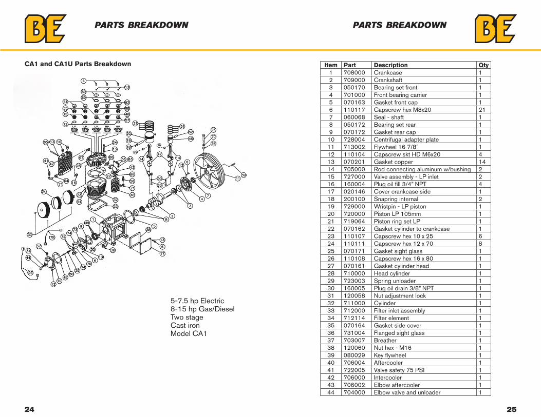
CA1 and CA1U Parts Breakdown
5-7.5 hp Electric8-15 hp Gas/DieselTwo stageCast ironModel CA1
parts breakdown
Item Part Description Qty1 708000 Crankcase 12 709000 Crankshaft 13 050170 Bearing set front 14 701000 Front bearing carrier 15 070163 Gasket front cap 16 110117 Capscrew hex M8x20 217 060068 Seal - shaft 18 050172 Bearing set rear 19 070172 Gasket rear cap 1
10 728004 Centrifugal adapter plate 111 713002 Flywheel 16 7/8” 112 110104 Capscrew skt HD M6x20 413 070201 Gasket copper 1414 705000 Rod connecting aluminum w/bushing 215 727000 Valve assembly - LP inlet 216 160004 Plug oil fill 3/4” NPT 417 020146 Cover crankcase side 118 200100 Snapring internal 219 729000 Wristpin - LP piston 120 720000 Piston LP 105mm 121 719064 Piston ring set LP 122 070162 Gasket cylinder to crankcase 123 110107 Capscrew hex 10 x 25 624 110111 Capscrew hex 12 x 70 825 070171 Gasket sight glass 126 110108 Capscrew hex 16 x 80 127 070161 Gasket cylinder head 128 710000 Head cylinder 129 723003 Spring unloader 130 160005 Plug oil drain 3/8” NPT 131 120058 Nut adjustment lock 132 711000 Cylinder 133 712000 Filter inlet assembly 134 712114 Filter element 135 070164 Gasket side cover 136 731004 Flanged sight glass 137 703007 Breather 138 120060 Nut hex - M16 139 080029 Key flywheel 140 706004 Aftercooler 141 722005 Valve safety 75 PSI 142 706000 Intercooler 143 706002 Elbow aftercooler 144 704000 Elbow valve and unloader 1
parts breakdown
26 27
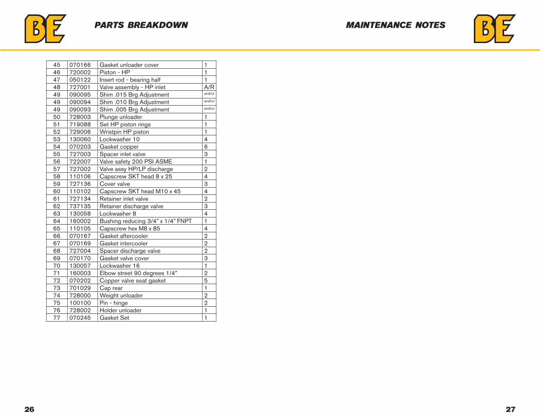
45 070166 Gasket unloader cover 146 720002 Piston - HP 147 050122 Insert rod - bearing half 148 727001 Valve assembly - HP inlet A/R49 090095 Shim .015 Brg Adjustment and/or
49 090094 Shim .010 Brg Adjustment and/or
49 090093 Shim .005 Brg Adjustment and/or
50 728003 Plunge unloader 151 719088 Set HP piston rings 152 729006 Wristpin HP piston 153 130060 Lockwasher 10 454 070203 Gasket copper 655 727003 Spacer inlet valve 356 722007 Valve safety 200 PSI ASME 157 727002 Valve assy HP/LP discharge 258 110106 Capscrew SKT head 8 x 25 459 727136 Cover valve 360 110102 Capscrew SKT head M10 x 45 461 727134 Retainer inlet valve 262 737135 Retainer discharge valve 363 130058 Lockwasher 8 464 160002 Bushing reducing 3/4” x 1/4” FNPT 165 110105 Capscrew hex M8 x 85 466 070167 Gasket aftercooler 267 070169 Gasket intercooler 268 727004 Spacer discharge valve 269 070170 Gasket valve cover 370 130057 Lockwasher 16 171 160003 Elbow street 90 degrees 1/4” 272 070202 Copper valve seat gasket 573 701029 Cap rear 174 728000 Weight unloader 275 100100 Pin - hinge 276 728002 Holder unloader 177 070245 Gasket Set 1
parts breakdown maintenance notes

If you need assistance with the assembly or operation
of your Compressor please call
1-866-850-6662
THE POWER YOU NEED.