Embed Size (px)
Citation preview
Power and productivity
for a better world™
800xA for Symphony Plus Harmony Configuration
System Version 6.0


800xA for Symphony Plus Harmony
Configuration
System Version 6.0

NOTICEThis document contains information about one or more ABB products and may include a description of or a reference to one or more standards that may be generally relevant to the ABB products. The presence of any such description of a standard or reference to a standard is not a representation that all of the ABB products referenced in this document support all of the features of the described or ref-erenced standard. In order to determine the specific features supported by a particular ABB product, the reader should consult the product specifications for the particular ABB product.
ABB may have one or more patents or pending patent applications protecting the intellectual property in the ABB products described in this document.
The information in this document is subject to change without notice and should not be construed as a commitment by ABB. ABB assumes no responsibility for any errors that may appear in this document.
Products described or referenced in this document are designed to be connected, and to communicate information and data via a secure network. It is the sole responsibility of the system/product owner to provide and continuously ensure a secure connection between the product and the system network and/or any other networks that may be connected.
The system/product owners must establish and maintain appropriate measures, including, but not lim-ited to, the installation of firewalls, application of authentication measures, encryption of data, installa-tion of antivirus programs, and so on, to protect the system, its products and networks, against security breaches, unauthorized access, interference, intrusion, leakage, and/or theft of data or information.
ABB verifies the function of released products and updates. However system/product owners are ulti-mately responsible to ensure that any system update (including but not limited to code changes, con-figuration file changes, third-party software updates or patches, hardware change out, and so on) is compatible with the security measures implemented. The system/product owners must verify that the system and associated products function as expected in the environment they are deployed.
In no event shall ABB be liable for direct, indirect, special, incidental or consequential damages of any nature or kind arising from the use of this document, nor shall ABB be liable for incidental or conse-quential damages arising from use of any software or hardware described in this document.
This document and parts thereof must not be reproduced or copied without written permission from ABB, and the contents thereof must not be imparted to a third party nor used for any unauthorized pur-pose.
The software or hardware described in this document is furnished under a license and may be used, copied, or disclosed only in accordance with the terms of such license. This product meets the require-ments specified in EMC Directive 2004/108/EC and in Low Voltage Directive 2006/95/EC.
TRADEMARKSAll rights to copyrights, registered trademarks, and trademarks reside with their respective owners.
Copyright © 2003-2015 by ABB.All rights reserved.
Release: October 2015Document number: 3BUA000157-600 A

3BUA000157-600 A 5
Table of Contents
About This User ManualGeneral ............................................................................................................................13
User Manual Conventions ...............................................................................................13
Warning, Caution, Information, and Tip Icons................................................................13
Terminology.....................................................................................................................14
Released User Manuals and Release Notes.....................................................................14
Intended User...................................................................................................................15
Section 1 - IntroductionOverview..........................................................................................................................17
Changes to Configuration in 800xA for Symphony Plus Harmony ................................17
Harmony Objects..................................................................................................18
Connectivity Server..............................................................................................19
Tags .............................................................................................................19
Uploader .............................................................................................................19
SOE Reporting .....................................................................................................19
Alarm and Event System......................................................................................19
Configuration Tools..............................................................................................19
Aspects and Settings ............................................................................................20
NLS Support.........................................................................................................20
Advanced Harmony Control System Monitoring ................................................20
Batch Support.......................................................................................................20
Signal Structure....................................................................................................20
Quality Definition ................................................................................................20
OCS Colors ..........................................................................................................20

Table of Contents
6 3BUA000157-600 A
Section 2 - Harmony ObjectsIntroduction ..................................................................................................................... 21
TagConfig Aspect View .................................................................................................. 21
Tabs ............................................................................................................ 21
Body ............................................................................................................ 21
Footer ............................................................................................................ 21
Configuration Actions ..................................................................................................... 22
Creating Harmony Server Objects ....................................................................... 22
Creating a New Harmony Object Tag.................................................................. 23
Creating a Harmony Controller Hierarchy Object............................................... 24
Modifying a Harmony Object Tag ....................................................................... 25
Deleting a Harmony Object Tag .......................................................................... 25
Renaming a Harmony Object Tag........................................................................ 26
Moving a Tag Between Connectivity Servers...................................................... 26
Modifying the Symphony System Definition ...................................................... 26
Online Change Notifications................................................................................ 27
Modifying the Connectivity Server Nodes .......................................................... 28
Common Object Properties ............................................................................................. 29
General Tab.......................................................................................................... 29
Naming Conventions and Guidelines.............................................................................. 30
Text Length .......................................................................................................... 30
Character Sets ...................................................................................................... 30
Section 3 - Connectivity ServerIntroduction ..................................................................................................................... 35
Harmony Server Object................................................................................................... 35
Server Tab........................................................................................................................ 35
Harmony Tab................................................................................................................... 36
Options ............................................................................................................ 36
Time Synchronization .......................................................................................... 38
Communication Errors......................................................................................... 39
Advanced Options................................................................................................ 39
Table of Contents
3BUA000157-600 A 7
Global Alarm Acknowledgement Configuration.............................................................39
Sending Global Alarm Acknowledgement Messages to the Loop ......................40
Receiving Global Alarm Acknowledgement from the Loop ...............................40
Section 4 - Harmony TagsIntroduction .....................................................................................................................41
Online Tag Configuration ................................................................................................41
Tag Types.........................................................................................................................41
Harmony Tag Objects ......................................................................................................45
Event Point Configuration ...............................................................................................46
Harmony Tab ...................................................................................................................46
Analog Tab ......................................................................................................................48
Analog Export Tab...........................................................................................................49
Enhanced Analog Input/Output Tab ................................................................................49
ASCII Tab........................................................................................................................50
Data Acquisition Analog Tab ..........................................................................................51
Device Driver Tab............................................................................................................52
Digital Tab .......................................................................................................................54
Digital Export Tab ...........................................................................................................54
Enhanced Digital Input/Output Tab.................................................................................55
Data Acquisition Digital Tab...........................................................................................55
Module Status ..................................................................................................................55
Multi State Device Driver Tab.........................................................................................57
PhaseX Tab ......................................................................................................................58
Remote Control Memory Tab..........................................................................................59
Remote Motor Control Block Tab ...................................................................................60
Remote Manual Set Constant Tab ...................................................................................62
Station Tab.......................................................................................................................63
Basic .............................................................................................................64
Cascade .............................................................................................................64
Ratio .............................................................................................................64
Text Selector ....................................................................................................................65
Table of Contents
8 3BUA000157-600 A
Section 5 - UploaderIntroduction ..................................................................................................................... 67
Settings Tab.......................................................................................................... 68
Import Tab............................................................................................................ 69
Export Tab............................................................................................................ 69
Section 6 - SOE ReportingIntroduction ..................................................................................................................... 71
Description ...................................................................................................................... 71
Specific Features ............................................................................................................. 71
Standard ............................................................................................................ 72
Summary ............................................................................................................ 72
Pre-fault ............................................................................................................ 72
Post-fault ............................................................................................................ 72
Snapshot ............................................................................................................ 72
Trigger Tag Monitoring................................................................................................... 73
SOE Reports Collection .................................................................................................. 73
SOE Reporting and Redundancy..................................................................................... 74
Distributed SOE Architecture ......................................................................................... 74
Rochester SOE Architecture ........................................................................................... 75
Distributed SOE Reporting Hardware............................................................................. 75
Rochester SOE Reporting Hardware............................................................................... 77
External Interfaces and Function Blocks ........................................................................ 78
SOE Objects .................................................................................................................... 78
SOE Recorder Tab........................................................................................................... 79
Index and SOE Point Name ............................................................................................ 79
Change (Create) SOE Map.............................................................................................. 80
SOE Digital Point Associations ...................................................................................... 80
SOE Report Tab .............................................................................................................. 82
Recorder ............................................................................................................ 82
Report Type.......................................................................................................... 82
Wait Time ............................................................................................................ 83
Table of Contents
3BUA000157-600 A 9
Active .............................................................................................................83
SOE Reports ....................................................................................................................84
Configuring the Rochester SER ......................................................................................89
Rochester ISM-1 Commands to Configure Pre-fault SOE Reports .....................89
Rochester ISM-1 Commands to Configure Post-Fault SOE Reports...................90
Other Rochester ISM-1 Commands .....................................................................91
Section 7 - System DefinitionIntroduction .....................................................................................................................93
Symphony System Definition Objects.............................................................................93
NLS Alarm Priority Text......................................................................................94
NLS Engineering Unit Descriptors ......................................................................94
NLS Event Comments..........................................................................................95
NLS Harmony PhaseX Fault Codes.....................................................................96
NLS Harmony PhaseX Substitutable Text ...........................................................96
NLS Harmony RMCB Text..................................................................................96
NLS Harmony Substitutable Text ........................................................................97
NLS Logic State Descriptors ...............................................................................97
NLS OPC Quality Text ........................................................................................98
NLS Symphony Substitutable Text ......................................................................98
NLS Text Selector Text ........................................................................................98
Configuring NLS Text Aspects .......................................................................................99
General Tab ..........................................................................................................99
Adding a NLS Resource ID ...............................................................................100
Modifying NLS Text ..........................................................................................100
Adding a Locale .................................................................................................100
Removing a Locale.............................................................................................100
XML Data Tab ...................................................................................................101
Section 8 - Alarm and Event SystemIntroduction ...................................................................................................................103
Alarm Collection Definition..........................................................................................103
Alarm Priority Mapping.....................................................................................104
Table of Contents
10 3BUA000157-600 A
Event Category Group ....................................................................................... 106
Class Extended Attribute Support...................................................................... 107
System Overview .......................................................................................................... 110
Alarms and Events ............................................................................................. 110
Event Point......................................................................................................... 111
Event Distribution System ................................................................................. 111
Event Concentrators........................................................................................... 112
Event Classifications.......................................................................................... 113
Event Categories ................................................................................................ 113
Event Point Definition ....................................................................................... 113
Section 9 - Configuration ToolsBulk Data Management................................................................................................. 119
Ad-hoc Bulk Changes ........................................................................................ 120
Pre-defined Template Bulk Changes.................................................................. 127
Environment Support .................................................................................................... 130
Uploading Harmony Tag Configuration to Engineering Environment .............. 130
Section 10 - Additional Harmony SettingsIntroduction ................................................................................................................... 137
Security Settings for Operating Parameters .................................................................. 137
800xA System Time Synchronization........................................................................... 138
Overview .......................................................................................................... 138
Time Synchronization ................................................................................................... 140
Time Adjustment........................................................................................................... 142
Current Time Adjust Status................................................................................ 142
New Time Adjust Target .................................................................................... 143
Authentication ............................................................................................................... 143
Hot Keys........................................................................................................................ 145
Section 11 - NLS SupportIntroduction ................................................................................................................... 147
Add New Locale to Desktop.............................................................................. 147

Table of Contents
3BUA000157-600 A 11
Add New Locale for Internet Explorer ..............................................................147
Backup of English Directory..............................................................................148
Localize Web Content ........................................................................................148
Localize Windows Applications.........................................................................149
Localize Faceplates ............................................................................................150
Software Upgrades .............................................................................................152
Section 12 - Advanced Harmony Control System MonitoringOverview........................................................................................................................153
Section 13 - Harmony Batch SupportIntroduction ...................................................................................................................155
Introduction ...................................................................................................................157
Harmony Property Types...............................................................................................157
Common Properties .......................................................................................................157
Common Analog Properties ..........................................................................................160
Data Acquisition Analog Properties ..............................................................................163
Enhanced Analog Input/Output Properties....................................................................172
Station Properties...........................................................................................................174
Remote Manual Set Constant Properties .......................................................................179
Common Digital Properties ...........................................................................................179
Data Acquisition Digital Properties...............................................................................182
Device Driver Properties ...............................................................................................183
Enhanced Digital Input/Output Properties ....................................................................184
Multi State Device Driver Properties.............................................................................185
Remote Control Memory Properties .............................................................................187
Remote Motor Control Block Properties.......................................................................188
Analog Export and Digital Export Properties ...............................................................190
Text Properties ...............................................................................................................194
Module Status Properties...............................................................................................197
PhaseX Properties..........................................................................................................203
SOE Report Properties ..................................................................................................208
Server Properties............................................................................................................212
Table of Contents
12 3BUA000157-600 A
Appendix B - Quality DefinitionIntroduction ................................................................................................................... 219
Description ....................................................................................................................219
Indicators....................................................................................................................... 220
OPC Quality Definition................................................................................................. 221
Harmony Quality Definition ......................................................................................... 222
Tag.Property Quality for Process Properties ................................................................. 223
Tag.Property Quality for Computed Properties............................................................. 223
Tag.Property Quality for Configuration Data................................................................ 224
Tag.Property Quality for Event Point Related Properties ............................................. 224
Tag Quality .................................................................................................................... 224
Properties .......................................................................................................... 224
Harmony Quality Information ........................................................................... 225
OPC Quality Flags ........................................................................................................ 226
Quality Bits ........................................................................................................ 227
Substatus Bits..................................................................................................... 227
Limit Bits .......................................................................................................... 229
OPCHDA Quality .............................................................................................. 230
Appendix C - OCS ColorsIntroduction ................................................................................................................... 231
Introduction ................................................................................................................... 235
Revision History............................................................................................................ 235
Updates in Revision Index A......................................................................................... 235
INDEX
3BUA000157-600 A 13
About This User Manual
General
800xA for Symphony Plus Harmony software allows connection to and control of the Harmony system via the 800xA Systems Operator Workplace. This user manual describes the configurations related to 800xA for Symphony Plus Harmony functions.
User Manual ConventionsMicrosoft Windows conventions are normally used for the standard presentation of material when entering text, key sequences, prompts, messages, menu items, screen elements, etc.
Warning, Caution, Information, and Tip IconsThis user manual includes Warning, Caution, and Information where appropriate to point out safety related or other important information. It also includes Tip to point
Any security measures described in this user manual, for example, for user access, password security, network security, firewalls, virus protection, etc., represent possible steps that a user of an 800xA System may want to consider based on a risk assessment for a particular application and installation. This risk assessment, as well as the proper implementation, configuration, installation, operation, administration, and maintenance of all relevant security related equipment, software, and procedures, are the responsibility of the user of the 800xA System.
Terminology About This User Manual
14 3BUA000157-600 A
out useful hints to the reader. The corresponding symbols should be interpreted as follows:
Although Warning hazards are related to personal injury, and Caution hazards are associated with equipment or property damage, it should be understood that operation of damaged equipment could, under certain operational conditions, result in degraded process performance leading to personal injury or death. Therefore, fully comply with all Warning and Caution notices.
TerminologyA complete and comprehensive list of Terms is included in System 800xA System Guide Functional Description (3BSE038018*). The listing includes terms and definitions that apply to the 800xA System where the usage is different from commonly accepted industry standard definitions and definitions given in standard dictionaries such as Webster’s Dictionary of Computer Terms.
Released User Manuals and Release NotesA complete list of all User Manuals and Release Notes applicable to System 800xA is provided in System 800xA Released User Documents (3BUA000263*).
Electrical warning icon indicates the presence of a hazard that could result in electrical shock.
Warning icon indicates the presence of a hazard that could result in personal injury.
Caution icon indicates important information or warning related to the concept discussed in the text. It might indicate the presence of a hazard that could result in corruption of software or damage to equipment/property.
Information icon alerts the reader to pertinent facts and conditions.
Tip icon indicates advice on, for example, how to design your project or how to use a certain function
About This User Manual Intended User
3BUA000157-600 A 15
System 800xA Released User Documents (3BUA000263*) is updated each time a document is updated or a new document is released. It is in pdf format and is provided in the following ways:
• Included on the documentation media provided with the system and published to ABB SolutionsBank when released as part of a major or minor release, Service Pack, Feature Pack, or System Revision.
• Published to ABB SolutionsBank when a User Manual or Release Note is updated in between any of the release cycles listed in the first bullet.
A product bulletin is published each time System 800xA Released User Documents (3BUA000263*) is updated and published to ABB SolutionsBank.
Intended UserThis user manual is intended for use by personnel responsible for configuring 800xA for Symphony Plus Harmony to operate within the 800xA System. This user manual assumes the configuration engineer or technician is familiar with Windows operating systems, Microsoft ® Internet Explorer, and the installed control system.

Intended User About This User Manual
16 3BUA000157-600 A

3BUA000157-600 A 17
Section 1 Introduction
Overview800xA for Symphony Plus Harmony communicates with the control systems through a Cnet-to-computer interface (IET800, PNI800).
800xA for Symphony Plus Harmony is a distributed process management and control system. Using a series of integrated Harmony control units, the system allows monitoring and control of process variables such as flow rate, temperature, and pressure according to a control configuration that the engineer or technician defines. A Harmony control unit is a controller and its I/O devices connected for communication on control network (Cnet).
800xA for Symphony Plus Harmony operates in a Windows environment on personal computer hardware. Using interactive process graphics, the operator can monitor and control all Analog loops and Digital devices interfaced to the network through Harmony control units.
800xA for Symphony Plus Harmony provides maintenance personnel with the capability to globally monitor the operating status of any system component on the network, and to diagnose component failures from any workstation.
800xA for Symphony Plus Harmony also provides the Harmony Executive Service. It is an 800xA service that controls underlying 800xA for Symphony Plus Harmony services.
Changes to Configuration in 800xA for Symphony Plus Harmony
The following configuration related changes have been made to 800xA for Symphony Plus Harmony in the 6.0 release:

Harmony Objects Section 1 Introduction
18 3BUA000157-600 A
• The SQL Server based ConfigServer Database that contained 800xA for Harmony Configuration data has been eliminated in the 6.0 release. The tag configuration data is now stored in the Aspect Directory.
• The Harmony Synchronizer Aspect, Tag Importer Exporter, and Import Export Configuration utility have been eliminated. A new Harmony Uploader Aspect has been added to allow Harmony tag configuration data to be imported to and exported from the Aspect Directory.
• A new TagConfig Aspect that supports Aspect Directory based tag configuration has been added. The new TagConfig Aspect also provides support for 800xA Engineering Environments and Versioning.
• The System Definition object type located under the Harmony OPC Server Network object has been eliminated. It has been replaced with a new INFI 90 System Definition object in the Library Structure and a new ServerConfig aspect on the Harmony OPC Server Network object.
• Remote Motor Control Block (RMCB) Text configuration has been removed from the Harmony Server TagConfig Aspect. RMCB Text configuration is now provided by a new NLS Text Set on the new INFI 90 System Definition object in the Library Structure.
• The Harmony Bulk Configuration Manager has been eliminated. The 800xA Bulk Data Manager can now be used to make bulk changes to 800xA for Symphony Plus Harmony TagConfig Aspects.
• The 800xA for Harmony Backup/Restore utility has been eliminated. 800xA for Symphony Plus Harmony tag configuration data can now be backed up and restored through the standard 800xA Aspect Directory backup/restore.
• The Harmony Server Monitor object and TagMonitor Aspects are no longer needed and have been eliminated.
Harmony Objects
800xA for Symphony Plus Harmony tag objects are configured from the TagConfig Aspect. This section describes the common aspect views of the Harmony objects. Refer to Section 2, Harmony Objects for more information on the object Harmony.

Section 1 Introduction Connectivity Server
3BUA000157-600 A 19
Connectivity Server
Connectivity server software is installed on selected nodes in the Harmony system. The connectivity server must be configured on each one of these nodes to be available to the system. Section 3, Connectivity Server describes the configuration of the Harmony connectivity server.
Tags
A Harmony tag is configured for each process point that is to be monitored by the Harmony connectivity server. A tag is required to perform control actions from a workstation running 800xA for Symphony Plus Harmony software. Section 4, Harmony Tags describes the configuration of the different Harmony tag types.
Uploader
The Uploader allows Harmony tag object configurations to be imported to or exported from the Aspect Directory. Section 5, Uploader describes the use of the Uploader.
SOE Reporting
SOE Reports allow monitoring of critical Digital points where the sequence of state changes for points or groups of points must be exactly known. Section 6, SOE Reporting describes the configuration of SOE Reports.
Alarm and Event System
The 800xA for Symphony Plus Harmony system provides services to define event conditions. Section 8, Alarm and Event System describes the alarm and event system.
Configuration Tools
Section 9, Configuration Tools describes the Bulk Data Manager and Environment Support.
Aspects and Settings Section 1 Introduction
20 3BUA000157-600 A
Aspects and Settings
Harmony aspects are described in this section as well as certain settings. Section 10, Additional Harmony Settings describes the different aspects.
NLS Support
800xA for Symphony Plus Harmony supports any locale. To configure a different locale, refer to Section 11, NLS Support.
Advanced Harmony Control System Monitoring
Section 12, Advanced Harmony Control System Monitoring describes the configuration of this optional Asset Monitor based feature.
Batch Support
Section 13, Harmony Batch Support describes details on 800xA for Symphony Plus Harmony Batch Management.
Signal Structure
A tag contains all information required to find a point in the process control configuration (function block) and to establish communication between it and Harmony. Appendix A, Signal Structure lists the Harmony tags with their signal structures.
Quality Definition
The purpose of this appendix is to describe the tag.property qualities in 800xA for Symphony Plus Harmony. Appendix B, Quality Definition lists the Harmony tag property qualities with definitions.
OCS Colors
Appendix C, OCS Colors lists the defaults colors used in faceplate and graphical elements.

3BUA000157-600 A 21
Section 2 Harmony Objects
IntroductionHarmony tag objects are configured from the TagConfig Aspect in the Control Structure inside the Workplace. This section describes the common aspect views of the Harmony objects.
TagConfig Aspect ViewAll TagConfig Aspect views have the same general appearance and behavior. The aspect views are divided into three common areas of Tabs, Body, and Footer.
Tabs
The tabs associated with the Aspect view depend on the type of object that is selected for Harmony. Harmony data that is common to multiple object types is presented in the same way to help make Harmony tasks easier and to improve efficiency. The General tab is included for every object type.
Body
The body area contains all of the configurable properties of any selected tab.
Footer
The footer area contains controls to apply or cancel changes.
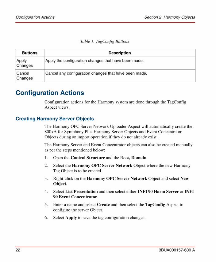
Table 1. TagConfig Buttons
Buttons Description
Apply Changes
Apply the configuration changes that have been made.
Cancel Changes
Cancel any configuration changes that have been made.
Configuration Actions Section 2 Harmony Objects
22 3BUA000157-600 A
Configuration ActionsConfiguration actions for the Harmony system are done through the TagConfig Aspect views.
Creating Harmony Server Objects
The Harmony OPC Server Network Uploader Aspect will automatically create the 800xA for Symphony Plus Harmony Server Objects and Event Concentrator Objects during an import operation if they do not already exist.
The Harmony Server and Event Concentrator objects can also be created manually as per the steps mentioned below:
1. Open the Control Structure and the Root, Domain.
2. Select the Harmony OPC Server Network Object where the new Harmony Tag Object is to be created.
3. Right-click on the Harmony OPC Server Network Object and select New Object.
4. Select List Presentation and then select either INFI 90 Harm Server or INFI 90 Event Concentrator.
5. Enter a name and select Create and then select the TagConfig Aspect to configure the server Object.
6. Select Apply to save the tag configuration changes.
Section 2 Harmony Objects Creating a New Harmony Object Tag
3BUA000157-600 A 23
7. Repeat Step 2 to Step 6 for each Harmony Server and Event Concentrator Objects to be created.
The Tag Objects can be added to the system using the Uploader, or by manually creating them. To create a Harmony Object Tag, refer to Creating a New Harmony Object Tag.
Creating a New Harmony Object Tag
1. Open the Control Structure and then open the Root, Domain.
2. Select the Harmony OPC Server Network Object where the new Harmony Tag Object is to be created.
3. Navigate to the Harmony Controller Hierarchy Object (For example: Loop1->Node16-> Module5) where the tag is to be added. Right-click on the
Copy-Paste of Harmony Objects is not allowed within a Harmony OPC Server Network Object. A message box is displayed informing the user that an Object with the same name already exists, followed by a transaction canceled message box an Object Paste error code message box. Click OK to dismiss these message boxes.

Creating a Harmony Controller Hierarchy Object Section 2 Harmony Objects
24 3BUA000157-600 A
INFI 90 Module object and select New Object as shown in Figure 1.
Figure 1. Control Structure
If the necessary Harmony Controller Hierarchy Objects do not exist, they can be created as well. To create the Objects, refer to Creating a Harmony Controller Hierarchy Object.
4. Select List Presentation and then select the Harmony tag type to create.
5. Enter a name and select Create.
6. Select the TagConfig Aspect for the new Object to configure the Block Address and other Tag attribute changes.
7. Select Apply to save the Tag configuration changes.
Repeat Step 2 to Step 7 to create each Harmony Tag Object.
Creating a Harmony Controller Hierarchy Object
1. Select the Object under which the Harmony Controller Hierarchy Object will be created (Harmony OPC Server Network Object, INFI90 Loop, or INFI90 Node).
Section 2 Harmony Objects Modifying a Harmony Object Tag
3BUA000157-600 A 25
2. Right-click and select New Object.
3. Select the desired Harmony Controller Hierarchy Object Type (INFI90 Loop, Node or Module).
4. Enter the name using the format "Loopx", "Nodex", or "Modulex" where x is the Harmony Loop, Node or Module number.
5. Select Create.
Modifying a Harmony Object Tag
1. Open the Control Structure.
2. Open the Root, Domain.
3. Open the Harmony OPC Server Network Object.
4. Navigate to the tag in the Harmony Control Structure hierarchy.
5. Select TagConfig in the list of Aspects.
While the TagConfig aspect can be opened and edited in multiple windows or locations at the same time, only the information in the last window or location that was saved will actually be saved. It is recommended that the TagConfig aspect only be opened, edited, and saved in one window or location at a time to avoid confusion.
6. Make any attribute changes.
7. Click Apply to save the changes.
Deleting a Harmony Object Tag
1. Open the Control Structure.
2. Open the Root, Domain.
3. Open the Harmony OPC Server Network Object.
4. Navigate to the tag in the Harmony Control Structure hierarchy.
5. Right-click on the Harmony Tag and then select Delete.
Renaming a Harmony Object Tag Section 2 Harmony Objects
26 3BUA000157-600 A
Renaming a Harmony Object Tag
1. Navigate to the Harmony Tag and then select the Tag to edit.
2. Select the Name Aspect.
3. Edit the name field and select Apply.
The Harmony Tag description can also be modified from the Name Aspect.
Data from renamed object tags may not be displayed by the Harmony Block Details, Harmony Module Details, Harmony Operating Parameters, and Harmony Diagnostics type aspects. Restart the Operator Workplace (clears an internally cached name) to view the data.
Moving a Tag Between Connectivity Servers
1. Navigate to the Harmony Tag to be moved in the Harmony Control Structure hierarchy.
2. Right-click on the Object and then select Cut.
3. Navigate to the Loop, Node, Module location under the Harmony OPC Server Network Object for the destination Harmony Server tag object. The Loop, Node and the Module Objects will need to be created, if they do not exist.
4. Right-click on the Module object and then select Paste.
5. If Enable On-line Change Notifications is disabled for the Harmony OPC Server Network Objects, then the Harmony Servers will need to be restarted to reflect the changes.
Modifying the Symphony System Definition
1. Navigate to the desired Harmony OPC Server Network Object and then Select the ServerConfig Aspect.
2. Select the NLS Text Sets pick-list to change the INFI 90 System Definition Object to be used for this Harmony OPC Server Network. Refer to Section 7, System Definition for more information.

Section 2 Harmony Objects Online Change Notifications
3BUA000157-600 A 27
Online Change Notifications
Select the Enable Online Change Notifications on the ServerConfig Aspect to automatically propagate online Tag configuration changes to the running Harmony Servers in this Harmony OPC Server Network.
If Enable Online Change Notifications is not selected, the Harmony Servers will need to be restarted to load any Tag configuration changes, additions and deletions that are made.
To make bulk configuration changes offline (data synchronization disabled):
1. Disable the Enable Online Change Notifications option.
2. Use Bulk Data Manager or the Uploader to make all Object changes.
3. One at a time, manually restart each Connectivity Server or use the Harmony Executive Service as follows:
a. De-select the Enabled option on the Configuration tab of the Harmony Executive Service located in the Service Structure as shown in Figure 2.
b. Click Apply and wait for the current status to change to Undefined.
Changes to the Harmony Server and Event Concentrator Tags are not propagated online and require a restart of the server to process the changes, regardless of choosing the Enable Online Change Notifications setting.
ABB does not recommend making bulk configuration changes online. When bulk changes are made, it is recommended that online change notifications are disabled. Each system may exhibit different update performance. ABB recommends disabling online changes if more than 100 tags are being added, updated or removed.
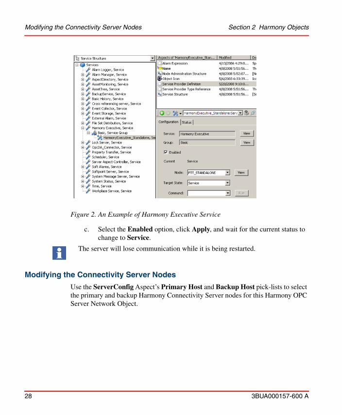
Figure 2. An Example of Harmony Executive Service
Modifying the Connectivity Server Nodes Section 2 Harmony Objects
28 3BUA000157-600 A
c. Select the Enabled option, click Apply, and wait for the current status to
change to Service.
The server will lose communication while it is being restarted.
Modifying the Connectivity Server Nodes
Use the ServerConfig Aspect’s Primary Host and Backup Host pick-lists to select the primary and backup Harmony Connectivity Server nodes for this Harmony OPC Server Network Object.

Section 2 Harmony Objects Common Object Properties
3BUA000157-600 A 29
Common Object PropertiesAll Harmony objects have some common object properties. These common properties identify the object and relate the objects to each other in the object hierarchy. The common properties are configured in the general tab of the object view.
General Tab
The General tab contains the following sections (Table 2).
Table 2. General Tab Fields
Field 1 Description
Identification - Information that identifies the object to the user throughout the Harmony system.
Type Selected during object creation. The type field cannot be changed. The behavior and the properties of an object are mainly dependent on the object type.
Name Used to identify an object at the user interface level. Internally the name is linked with a unique ID. References to objects are stored by using the unique ID only. If the name of an object that another object references is changed, the reference will stay the same. At the browser level the most recent name will be used to present an object. Object names must be unique. The field accepts from up to 32 characters. The Name field can only be changed in the Name Aspect.
Description Defines more detailed information about an Object. The Description is displayed in several views (faceplates). The field accepts up to 64 characters. The Description field can only be changed in the Name Aspect.
User Text Allows user supplied text to be associated with the object.
User Index 2 Provides a method to index objects using some other indexing scheme.
NOTES: 1. Refer to Naming Conventions and Guidelines on page 30 for a description of the legal character set for names.2. This field is currently used by Operate IT conversion tools to map the original object in Operate IT to a new object in Harmony.
Naming Conventions and Guidelines Section 2 Harmony Objects
30 3BUA000157-600 A
Naming Conventions and GuidelinesThe following sections define naming conventions and guidelines for objects and properties. These guidelines mainly describe character length restrictions and list supported characters. The restrictions apply to object names and property names only. The usable character set for other text strings do not have these restrictions.
Text Length
Table 3. Text Lengths
EntityMaximum
CharactersDescriptions
Object Name 32 Identifies the object in the system. The period (.) separator between object name and property name is not considered part of the name.
Property Name
32 Identifies a property inside of an object. When the property name consists of multiple parts (signal name/selector) separated by a slash (/), the separator is considered part of the property name.
Description 64 A description of the purpose of the object that is displayed in specific views such as in faceplates.
The lengths specified in Table 3 for the different properties are the maximum number that can be handled by the system. This does not imply that the maximum number of characters will always be shown in every display or application. The character space in some applications is limited, and in some cases, field widths are user adjustable. When a string is truncated in a display, the whole string is usually shown in the form of a tool tip.
Character Sets
Three groups of characters for object names and property names are used.
Section 2 Harmony Objects Character Sets
3BUA000157-600 A 31
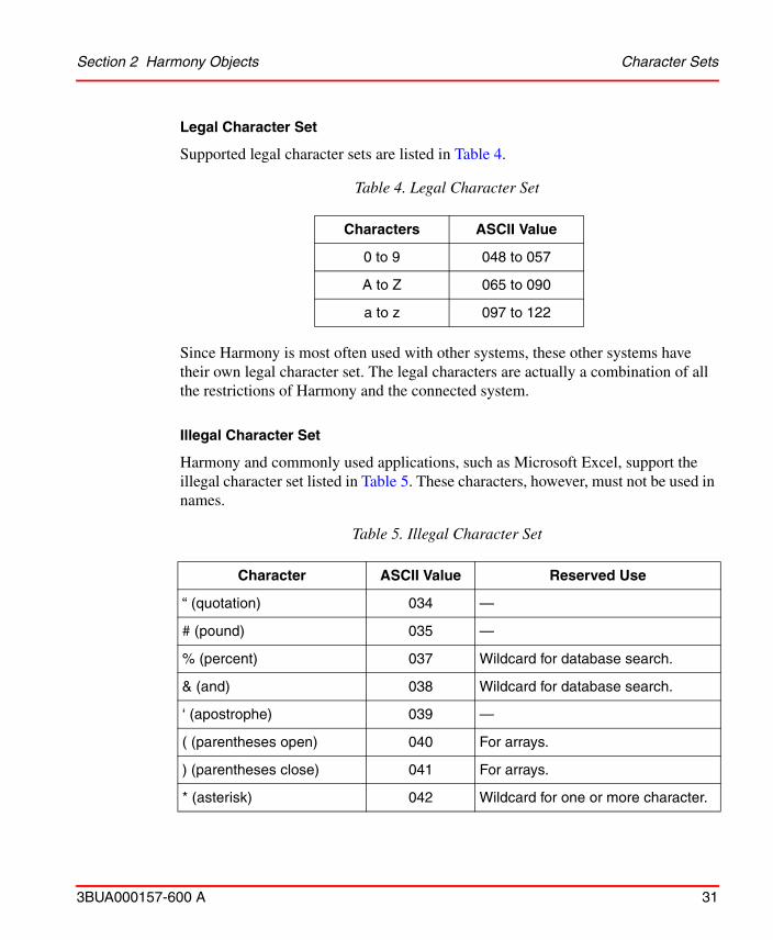
Legal Character Set
Supported legal character sets are listed in Table 4.
Since Harmony is most often used with other systems, these other systems have their own legal character set. The legal characters are actually a combination of all the restrictions of Harmony and the connected system.
Illegal Character Set
Harmony and commonly used applications, such as Microsoft Excel, support the illegal character set listed in Table 5. These characters, however, must not be used in names.
Table 4. Legal Character Set
Characters ASCII Value
0 to 9 048 to 057
A to Z 065 to 090
a to z 097 to 122
Table 5. Illegal Character Set
Character ASCII Value Reserved Use
“ (quotation) 034 —
# (pound) 035 —
% (percent) 037 Wildcard for database search.
& (and) 038 Wildcard for database search.
‘ (apostrophe) 039 —
( (parentheses open) 040 For arrays.
) (parentheses close) 041 For arrays.
* (asterisk) 042 Wildcard for one or more character.
Character Sets Section 2 Harmony Objects
32 3BUA000157-600 A
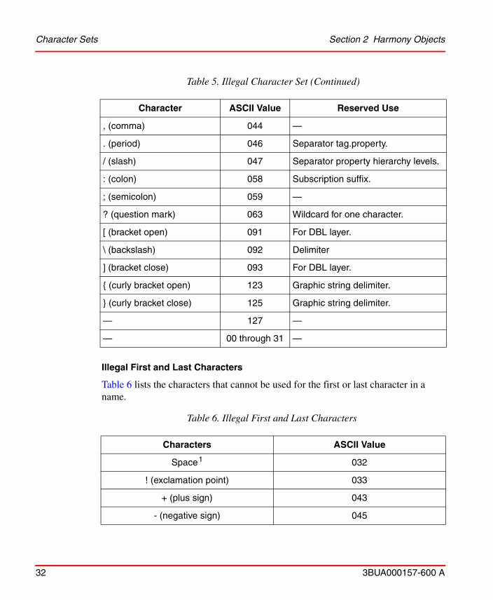
Illegal First and Last Characters
Table 6 lists the characters that cannot be used for the first or last character in a name.
, (comma) 044 —
. (period) 046 Separator tag.property.
/ (slash) 047 Separator property hierarchy levels.
: (colon) 058 Subscription suffix.
; (semicolon) 059 —
? (question mark) 063 Wildcard for one character.
[ (bracket open) 091 For DBL layer.
\ (backslash) 092 Delimiter
] (bracket close) 093 For DBL layer.
{ (curly bracket open) 123 Graphic string delimiter.
} (curly bracket close) 125 Graphic string delimiter.
— 127 —
— 00 through 31 —
Table 6. Illegal First and Last Characters
Characters ASCII Value
Space 1 032
! (exclamation point) 033
+ (plus sign) 043
- (negative sign) 045
Table 5. Illegal Character Set (Continued)
Character ASCII Value Reserved Use
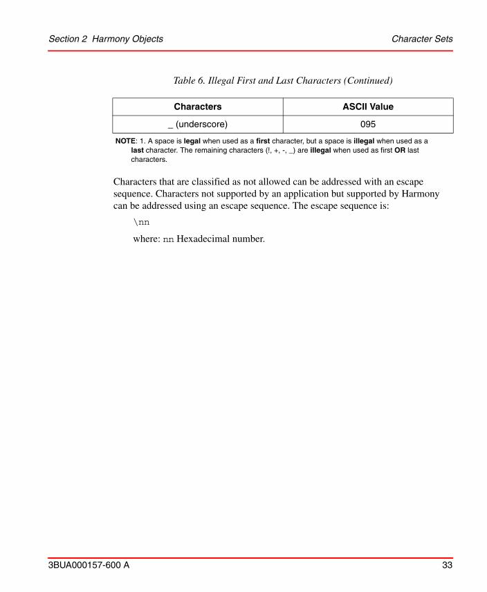
Section 2 Harmony Objects Character Sets
3BUA000157-600 A 33
Characters that are classified as not allowed can be addressed with an escape sequence. Characters not supported by an application but supported by Harmony can be addressed using an escape sequence. The escape sequence is:
\nn
where: nn Hexadecimal number.
_ (underscore) 095
NOTE: 1. A space is legal when used as a first character, but a space is illegal when used as a last character. The remaining characters (!, +, -, _) are illegal when used as first OR last characters.
Table 6. Illegal First and Last Characters (Continued)
Characters ASCII Value
Character Sets Section 2 Harmony Objects
34 3BUA000157-600 A
3BUA000157-600 A 35
Section 3 Connectivity Server
IntroductionThe connectivity server is hosted by a Harmony system node. The Server object is configured and assigned to the host node that has the Harmony Server software installed. This section describes the configuration of the Harmony Server object.
Harmony Server ObjectThe Harmony Server object contains information related to the connectivity server. A Harmony Server object has to be configured for every node that is to host a Harmony Server. Table 7 describes the Server object properties.
Server TabThe Server tab is used to configure Alarms for Redundancy, Licensing and Internal Errors. Redundancy State is no longer configured in the Server Tab. Harmony Connectivity configuration is configured in the ServerConfig Aspect on the Harmony OPC Server Network Object.
Table 7. Harmony Server Object Properties
Properties Description
General Common object properties.
Server Server properties similar to other Server objects. Refer to Server Tab on page 35 for additional information.
Harmony Refer to Harmony Tab on page 36 for more information.

Harmony Tab Section 3 Connectivity Server
36 3BUA000157-600 A
Harmony TabThe Harmony tab is used to configure specific information related to the Harmony control system (Figure 3). The fields in this view are described in the following paragraphs.
Options
Following are the options available under Harmony Tab:
Filter Bad Quality Alarms
Filters bad quality alarms caused by hardware failure.
Figure 3. Harmony Tab
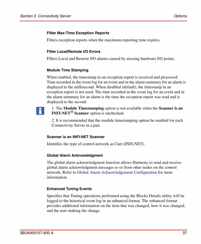
Section 3 Connectivity Server Options
3BUA000157-600 A 37
Filter Max-Time Exception Reports
Filters exception reports when the maximum reporting time expires.
Filter Local/Remote I/O Errors
Filters Local and Remote I/O alarms caused by missing hardware I/O points.
Module Time Stamping
When enabled, the timestamp in an exception report is received and processed. Time recorded in the event log for an event and in the alarm summary for an alarm is displayed to the millisecond. When disabled (default), the timestamp in an exception report is not used. The time recorded in the event log for an event and in the alarm summary for an alarm is the time the exception report was read and is displayed to the second.
Scanner is an INFI-NET Scanner
Identifies the type of control network as Cnet (INFI-NET).
Global Alarm Acknowledgment
The global alarm acknowledgment function allows Harmony to send and receive global alarm acknowledgment messages to or from other nodes on the control network. Refer to Global Alarm Acknowledgement Configuration for more information.
Enhanced Tuning Events
Specifies that Tuning operations performed using the Blocks Details utility will be logged to the historical event log in an enhanced format. The enhanced format provides additional information on the item that was changed, how it was changed, and the user making the change.
1. The Module Timestamping option is not available when the Scanner is an INFI-NET ® Scanner option is unchecked.
2. It is recommended that the module timestamping option be enabled for each Connectivity Server in a pair.
Time Synchronization Section 3 Connectivity Server
38 3BUA000157-600 A
Time Synchronization
Enable Time Synchronization
Determines whether or not the Server receives and sends the time synchronization on the network. When enabled, the Server is in time synchronization with the control network.
Accuracy
Time synchronization accuracy of the Server is valid when the Server is in time synchronization mode. The options are:
• Low accuracy (lowest accuracy); priority 0.• Low accuracy battery backed; priority 3.• High accuracy battery backed; priority 6.• IIOIS20 node; priority 9.• IIOIS20 SCSI; priority 10.• PIMS SCSI; priority 11.• Satellite clock system (highest accuracy); priority 12.
These accuracy settings are only used when negotiating for time mastership with other nodes in the underlying Harmony control network.
Master Update Period
Master update period is the frequency that Harmony Server synchronizes time with the underlying Harmony control network. This property is used only when Time Synchronization is enabled. The permissible values are 120 to 3540 seconds.
Message Wait Period
Message wait period is the Period that Harmony Server waits before attempting to assume time mastership on the control network. This property is used only when Time Synchronization is enabled. The permissible values are between 180 and 3660 seconds. Additionally, the configured value must greater than the Master Update Period.

Section 3 Connectivity Server Communication Errors
3BUA000157-600 A 39
Run RTDS in OIS Mode
Run RTDS in OIS Mode allows the connectivity server to time sync properly with an OIS component. This setting should only be set if both OIS nodes and Harmony are being time synchronized on the same loop.
Enable automatic DST adjustment for SEM Module
Enabling this option will cause the Harmony Server to adjust the INFI 90 network time when a Daylight Savings Time adjustment is made by Windows on the Harmony Server node.
Communication Errors
Allows the user to configure the Alarm Comment text and Alarm Priority for Harmony Server Communication Error events.
Advanced Options
Harmony Namespace Support
Harmony namespace support allows the Harmony Server to process requests for non tag information, such as block detail and module detail status information. This setting should be enabled on the connectivity server in order for the Block Details and Module Details applications to function properly.
Turn Off Persistence for Export Tags on Bulk Update
Turn Off Persistence for Export Tags on Bulk Update specifies the Harmony Server to not persist values written to export type tags in bulk mode to the persistent database. This facilitates faster and more efficient bulk data exporting.
Global Alarm Acknowledgement ConfigurationThe global alarm acknowledgment function allows acknowledged alarms on one node to be automatically seen by other nodes on the same INFI-NET loop. Alarms acknowledged on one node can be broadcasted to the other independent nodes through the INFI-NET loop. Each node can be configured to send or receive alarm acknowledgments. This function is available for Harmony systems only.
Sending Global Alarm Acknowledgement Messages to the Loop Section 3 Connectivity Server
40 3BUA000157-600 A
Sending Global Alarm Acknowledgement Messages to the Loop
Enable Tag Acknowledgment Broadcast
To broadcast an alarm acknowledgement for a specific Harmony tag:
– Select the Tag Acknowledgment Broadcast Enable check box on the Harmony Tab of the tag.
Selecting the checkbox enables the connectivity server to broadcast the alarm acknowledgement for this tag on the communication highway.
Enable Acknowledgment Transmission
Configure the module status tag for each node to which the connectivity server transmits the alarm acknowledgment messages. For each module status tag, on the Module tab, select the Enable Alarm Acknowledgment Transmission check box to have the connectivity server transmit any recently acknowledged alarms. Broadcasts will only be sent to a node when the corresponding module status tag is configured and has alarm acknowledgment transmission enabled.
Receiving Global Alarm Acknowledgement from the Loop
Configure the Harmony Server tag to enable receiving global alarm acknowledgment messages from other nodes on the loop.
On the Harmony tab, select the Global Alarm Acknowledgement check box to enable the connectivity server to process the Global Alarm Acknowledgement messages received through the INFI-NET loop.
The connectivity server applies the alarm acknowledgement to the harmony tag that has the same Harmony address as the broadcast tag.
3BUA000157-600 A 41
Section 4 Harmony Tags
IntroductionThis section describes the configuration of Harmony tags. A tag is required to access Harmony data and to perform control actions from a workstation. The tags can be configured from any system node.
The system must have a Harmony connectivity server installed. Once configured, Harmony tag data can be used in Harmony functions such as process displays, reports, event pages, alarming, etc.
Online Tag ConfigurationHarmony allows online tag configuration. Tags can be added, deleted, changed, and updated to the system.
The Enable Online Change Notifications option in the ServerConfig Aspect on the Harmony OPC Server Network Object where the Tag is located will specify whether or not the Tag configuration changes are processed online. For more information, go to Online Change Notifications on page 27
Tag TypesA tag represents either an Analog or Digital exception reporting block or a Station, Device Driver, or control block in a Harmony controller. Define a tag for each process variable that Harmony is to monitor and for each process device available

Tag Types Section 4 Harmony Tags
42 3BUA000157-600 A
for control. Also, a tag can represent a system controller or communications interface.
A tag contains all information required to find a point in the process control configuration (function block) and to establish communication between it and Harmony. Not all processor function blocks can be assigned a tag.
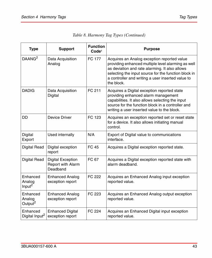
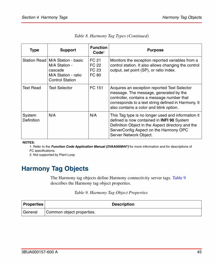
Each tag type available in Harmony can provide access to one or more function codes (FC). Table 8 lists and describes the Harmony tag types. Refer to Appendix A, Signal Structure for the signal structure of all the Harmony tag types.
Harmony Tag objects should be added to the Functional Structure with the Insert Object Operation or by selecting the Import Functional Structure Assignments option when Importing tags with the Uploader.
Table 8. Harmony Tag Types
Type SupportFunction
Code1 Purpose
Harm Server Used internally N/A Configures specific information related to the Harmony control system.
Analog Export
Used internally N/A Export of Analog value to communications interface.
Analog Read Analog exception report
FC 30 Acquires an Analog exception reported value.
Analog Read Analog Exception Report with High/Low Alarm Deadband
FC 48 Acquires an Analog exception reported value with alarm deadband.
ASCIIText2 User defined data export
FC 194 Enables communication between Harmony and a C language or batch program running in a controller. Allows transfer of text strings.
Section 4 Harmony Tags Tag Types
3BUA000157-600 A 43
DAANG2 Data Acquisition Analog
FC 177 Acquires an Analog exception reported value providing enhanced multiple level alarming as well as deviation and rate alarming. It also allows selecting the input source for the function block in a controller and writing a user inserted value to the block.
DADIG Data Acquisition Digital
FC 211 Acquires a Digital exception reported state providing enhanced alarm management capabilities. It also allows selecting the input source for the function block in a controller and writing a user inserted value to the block.
DD Device Driver FC 123 Acquires an exception reported set or reset state for a device. It also allows initiating manual control.
Digital Export
Used internally N/A Export of Digital value to communications interface.
Digital Read Digital exception report
FC 45 Acquires a Digital exception reported state.
Digital Read Digital Exception Report with Alarm Deadband
FC 67 Acquires a Digital exception reported state with alarm deadband.
Enhanced Analog Input2
Enhanced Analog exception report
FC 222 Acquires an Enhanced Analog input exception reported value.
Enhanced Analog Output2
Enhanced Analog exception report
FC 223 Acquires an Enhanced Analog output exception reported value.
Enhanced Digital Input2
Enhanced Digital exception report
FC 224 Acquires an Enhanced Digital input exception reported value.
Table 8. Harmony Tag Types (Continued)
Type SupportFunction
Code1 Purpose
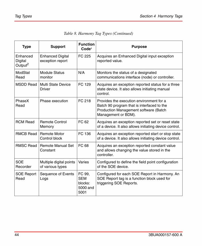
Tag Types Section 4 Harmony Tags
44 3BUA000157-600 A
Enhanced Digital Output2
Enhanced Digital exception report
FC 225 Acquires an Enhanced Digital input exception reported value.
ModStat Read
Module Status monitor
N/A Monitors the status of a designated communications interface (node) or controller.
MSDD Read Multi State Device Driver
FC 129 Acquires an exception reported status for a three state device. It also allows initiating manual control.
PhaseX Read
Phase execution FC 218 Provides the execution environment for a Batch 90 program that is interfaced to the Production Management software (Batch Management or BDM).
RCM Read Remote Control Memory
FC 62 Acquires an exception reported set or reset state of a device. It also allows initiating device control.
RMCB Read Remote Motor Control block
FC 136 Acquires an exception reported start or stop state of a device. It also allows initiating device control.
RMSC Read Remote Manual Set Constant
FC 68 Acquires an exception reported constant value and allows changing the value stored in the controller.
SOE Recorder
Multiple digital points of various types
Varies Configured to define the field point configuration of the SOE device.
SOE Report Read
Sequence of Events Logs
FC 99, SEM blocks:5000 and 5001
Configured for each SOE Report in Harmony. An SOE Report tag is a function block used for triggering SOE Reports.
Table 8. Harmony Tag Types (Continued)
Type SupportFunction
Code1 Purpose
Section 4 Harmony Tags Harmony Tag Objects
3BUA000157-600 A 45
Harmony Tag Objects
The Harmony tag objects define Harmony connectivity server tags. Table 9 describes the Harmony tag object properties.
Station Read M/A Station - basicM/A Station - cascadeM/A Station - ratioControl Station
FC 21FC 22FC 23FC 80
Monitors the exception reported variables from a control station. It also allows changing the control output, set point (SP), or ratio index.
Text Read Text Selector FC 151 Acquires an exception reported Text Selector message. The message, generated by the controller, contains a message number that corresponds to a text string defined in Harmony. It also contains a color and blink option.
System Definition
N/A N/A This Tag type is no longer used and information it defined is now contained in INFI 90 System Definition Object in the Aspect directory and the ServerConfig Aspect on the Harmony OPC Server Network Object.
NOTES:1. Refer to the Function Code Application Manual (2VAA000844*) for more information and for descriptions of FC specifications.2. Not supported by Plant Loop.
Table 9. Harmony Tag Object Properties
Properties Description
General Common object properties.
Table 8. Harmony Tag Types (Continued)
Type SupportFunction
Code1 Purpose
Event Point Configuration Section 4 Harmony Tags
46 3BUA000157-600 A
Event Point ConfigurationEach tag in the Harmony system that generates events has configurable event points. The event point configuration permits the assignment of priorities and alarm texts to be associated with the event point. The event point configuration also determines if the event is an alarm or if it needs acknowledgement. When the complement input signal is enabled, the zero state of the signal represents the active state of the event point.
Harmony TabThe Harmony tab is configured for every Harmony tag object (Figure 4). This tab determines system information that identifies the tag in the Harmony system and the actions that can be performed on the tag in the control system.
To configure the Harmony tab:
1. Configure the bad quality event point. Refer to Event Point Configuration on page 46 for more information.
2. In the Inhibit area, select a tag.property for automatic alarm inhibiting. This property is used to inhibit alarm indications for a selected tag. Alarm inhibiting is based on the current value of the inhibit tag. The Tag Property should be blank to disable automatic alarm inhibiting.
Harmony Refer to Harmony Tab on page 46 for more information.
Tag specific
Each type of tag object has unique properties. Refer to the appropriate tab for more information.
Table 9. Harmony Tag Object Properties (Continued)
Properties Description

Section 4 Harmony Tags Harmony Tab
3BUA000157-600 A 47
3. Enter the address of the function block that contains the FC that the tag is to
monitor. The fields are:
Loop The communication highway for the Harmony system. Valid entries are 0 to 250.
Node An interconnection point on the data highway. Valid entries are 1 to 250.
Module A device in the Harmony control system. Valid entries are 1 to 31.
Block Location of a specific FC in the controller. Valid entries are one to 9,998 for the BRC-100/BRC-200, IMMFP11, and IMMFP12 controllers and 31,998 for the HAC controller.
The loop, node, module, and block settings must be unique within a system.
4. In the options area enable or disable tag acknowledgment broadcast enabled. This determines whether or not an alarm acknowledgment is transmitted to other nodes on the loop.
Figure 4. Harmony Tab
Analog Tab Section 4 Harmony Tags
48 3BUA000157-600 A
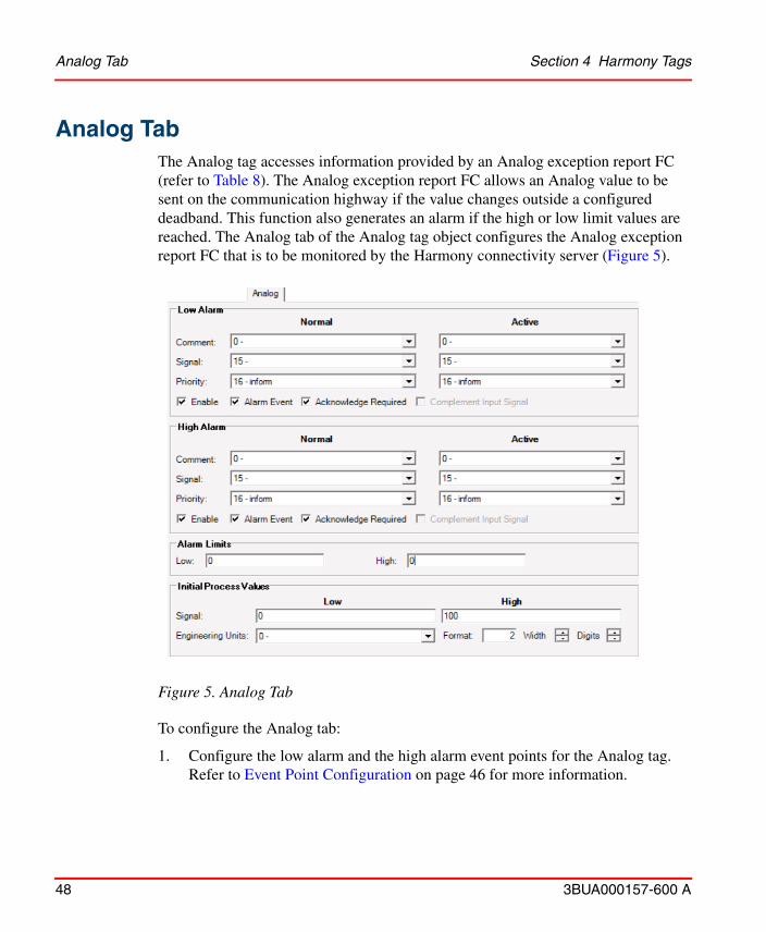
Analog TabThe Analog tag accesses information provided by an Analog exception report FC (refer to Table 8). The Analog exception report FC allows an Analog value to be sent on the communication highway if the value changes outside a configured deadband. This function also generates an alarm if the high or low limit values are reached. The Analog tab of the Analog tag object configures the Analog exception report FC that is to be monitored by the Harmony connectivity server (Figure 5).
To configure the Analog tab:
1. Configure the low alarm and the high alarm event points for the Analog tag. Refer to Event Point Configuration on page 46 for more information.
Figure 5. Analog Tab
Section 4 Harmony Tags Analog Export Tab
3BUA000157-600 A 49
2. Set the alarm limits for the tag. The alarm limits trigger the high and the low alarm event points when the value goes outside the respective limit.
3. Set the high and low range values of the process value.
4. A controller reports the index number that associates an engineering unit of measurement with this tag. A list of valid fixed and user defined engineering units can be viewed in the NLS Engineering Unit Aspect under the INFI90 System Definition Object.
5. Set the display format using the width (number of characters) and digits (number of decimal digits) controls. The syntax of this field is:
Number of characters X 10 + number of decimal digits
Analog Export TabThe Analog Export tag provides the ability to export an exception report value to the Harmony system through the Cnet-to-computer interface. The Analog Export tab of the Analog Export tag object is similar to the Analog tab (Figure 5). Refer to Analog Tab on page 48 for more information.
Enhanced Analog Input/Output TabThe Enhanced Analog input tag accesses information provided by an Analog in/channel FC (refer to Table 8 for the FC numbers). The exception reporting Analog in/channel FC provides addressing, startup, runtime, override, and failure mode specifications for an individual or redundant pair of Analog input channels on a Harmony I/O block. An Enhanced Analog input tag is configured for each Analog in/channel FC that is to be monitored by a Harmony connectivity server.
The Enhanced Analog output tag accesses information provided by an Analog out/channel FC (refer to Table 8 for the FC numbers). The exception reporting Analog out/channel FC provides addressing, startup, runtime, and failure mode specifications for an individual or redundant pair of Analog output channels on a
The values set in Step 2 through Step 4 are configurable for initial value purposes only. They will be overwritten by values reported from the function block after startup.
ASCII Tab Section 4 Harmony Tags
50 3BUA000157-600 A
Harmony I/O block. An Enhanced Analog output tag is configured for each Analog out/channel FC that is to be monitored by a Harmony connectivity server.
The Enhanced Analog tab of the Enhanced Analog tag object is similar to the Analog tab (Figure 5). Refer to Analog Tab on page 48 for more information.
ASCII TabThe ASCII Text string tag interfaces with a user defined data export FC (refer to Table 8). The user defined data export FC outputs user data through an exception report. The ASCII tab of the ASCII Text string tag object configures a user defined data export FC that is to be monitored by a Harmony connectivity server (Figure 6).
To configure the ASCII tab:
1. Configure the alarm status event point for the tag. Refer to Event Point Configuration on page 46 for more information.
2. Set the maximum text width. If this string length is less than the actual length of the exception reported text string, truncation will occur. This is considered to be remote truncation since the communications interface unit of Harmony uses the value to determine the maximum length of the text string it will accept. The permissible values are 0 to 80.
Figure 6. ASCII Tab
Section 4 Harmony Tags Data Acquisition Analog Tab
3BUA000157-600 A 51
3. The Operator Control Enable option determines whether or not operator control of the text string export block in the controller is permitted. When enabled, control can be performed by using the keyboard. The results of the operator actions can be seen on the screen. When disabled, Harmony provides information but does not allow control.
Data Acquisition Analog TabThe Data Acquisition Analog (DAANG) tag interfaces with a user defined DAANG FC (refer to Table 8). The DAANG FC provides a number of unique data selection, conditioning and monitoring functions. These include support for enhanced alarm management capabilities at the module level of a Harmony system. The DAANG tab of the DAANG tag object configures the DAANG FC that is to be monitored by the Harmony connectivity server (Figure 7).
Figure 7. DAANG Tab

Device Driver Tab Section 4 Harmony Tags
52 3BUA000157-600 A
To configure the DAANG tab:
1. Configure the low alarm and the high alarm event points. Refer to Event Point Configuration on page 46 for more information.
2. Set the alarm limits for the tag. The alarm limits trigger the high and the low alarm event points when the value goes outside the respective limit.
3. Set the high and low range values of the process value.
4. Select a configured engineering unit descriptor from the pick list. The controller reports the index number that associates an engineering unit of measurement with this tag. A list of valid fixed and user defined engineering units can be viewed in the NLS Engineering Unit Aspect under the INFI90 System Definition Object.
5. Set the display format using the width (number of characters) and digits (number of decimal digits) controls. The syntax of this field is:Number of characters X 10 + number of decimal digits
The values set in Step 2 through Step 4 are configurable for initial value purposes only. They will be overwritten by values reported from the function block after startup.
6. Scroll down through the page and configure rest of the event points for the DAANG tag. Refer to Event Point Configuration on page 46 for more information.
Device Driver TabThe Device Driver tag accesses information provided by a Device Driver FC (refer to Table 8). The Device Driver FC interfaces the control system to a field device. It provides control and accepts feedback from its assigned control device. The control output status represents the status of the device determined from the feedback inputs as good, bad, or waiting. The Device Driver tab of the Device Driver tag object configures the Device Driver FC that is to be monitored by the Harmony

Section 4 Harmony Tags Device Driver Tab
3BUA000157-600 A 53
connectivity server (Figure 8).
To configure the Device Driver tab:
1. Configure the output state and the state change event points. Refer to Event Point Configuration on page 46 for more information.
2. Set the normal and the active signal text for the first feedback state by selecting one from the pick list.
3. If reverse logic is to be used for this tag (zero is active) enable complement input signal.
4. Repeat Step 2 through Step 3 for the second feedback state.
Figure 8. Device Driver Tab
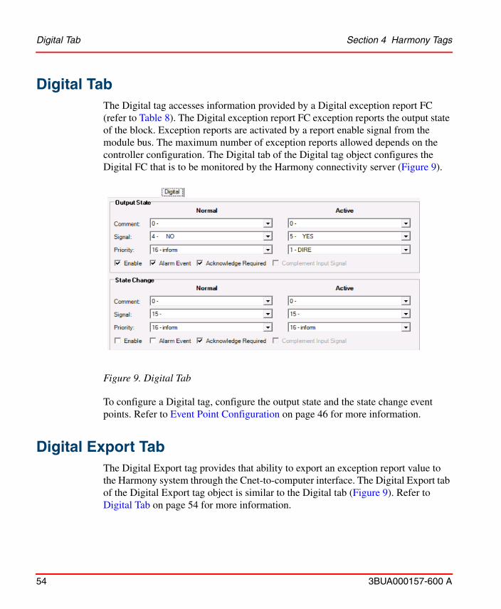
Digital Tab Section 4 Harmony Tags
54 3BUA000157-600 A
Digital TabThe Digital tag accesses information provided by a Digital exception report FC (refer to Table 8). The Digital exception report FC exception reports the output state of the block. Exception reports are activated by a report enable signal from the module bus. The maximum number of exception reports allowed depends on the controller configuration. The Digital tab of the Digital tag object configures the Digital FC that is to be monitored by the Harmony connectivity server (Figure 9).
To configure a Digital tag, configure the output state and the state change event points. Refer to Event Point Configuration on page 46 for more information.
Digital Export TabThe Digital Export tag provides that ability to export an exception report value to the Harmony system through the Cnet-to-computer interface. The Digital Export tab of the Digital Export tag object is similar to the Digital tab (Figure 9). Refer to Digital Tab on page 54 for more information.
Figure 9. Digital Tab
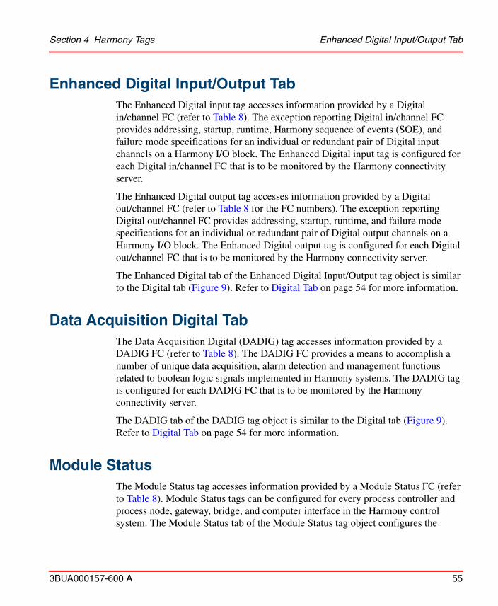
Section 4 Harmony Tags Enhanced Digital Input/Output Tab
3BUA000157-600 A 55
Enhanced Digital Input/Output TabThe Enhanced Digital input tag accesses information provided by a Digital in/channel FC (refer to Table 8). The exception reporting Digital in/channel FC provides addressing, startup, runtime, Harmony sequence of events (SOE), and failure mode specifications for an individual or redundant pair of Digital input channels on a Harmony I/O block. The Enhanced Digital input tag is configured for each Digital in/channel FC that is to be monitored by the Harmony connectivity server.
The Enhanced Digital output tag accesses information provided by a Digital out/channel FC (refer to Table 8 for the FC numbers). The exception reporting Digital out/channel FC provides addressing, startup, runtime, and failure mode specifications for an individual or redundant pair of Digital output channels on a Harmony I/O block. The Enhanced Digital output tag is configured for each Digital out/channel FC that is to be monitored by the Harmony connectivity server.
The Enhanced Digital tab of the Enhanced Digital Input/Output tag object is similar to the Digital tab (Figure 9). Refer to Digital Tab on page 54 for more information.
Data Acquisition Digital TabThe Data Acquisition Digital (DADIG) tag accesses information provided by a DADIG FC (refer to Table 8). The DADIG FC provides a means to accomplish a number of unique data acquisition, alarm detection and management functions related to boolean logic signals implemented in Harmony systems. The DADIG tag is configured for each DADIG FC that is to be monitored by the Harmony connectivity server.
The DADIG tab of the DADIG tag object is similar to the Digital tab (Figure 9). Refer to Digital Tab on page 54 for more information.
Module StatusThe Module Status tag accesses information provided by a Module Status FC (refer to Table 8). Module Status tags can be configured for every process controller and process node, gateway, bridge, and computer interface in the Harmony control system. The Module Status tab of the Module Status tag object configures the
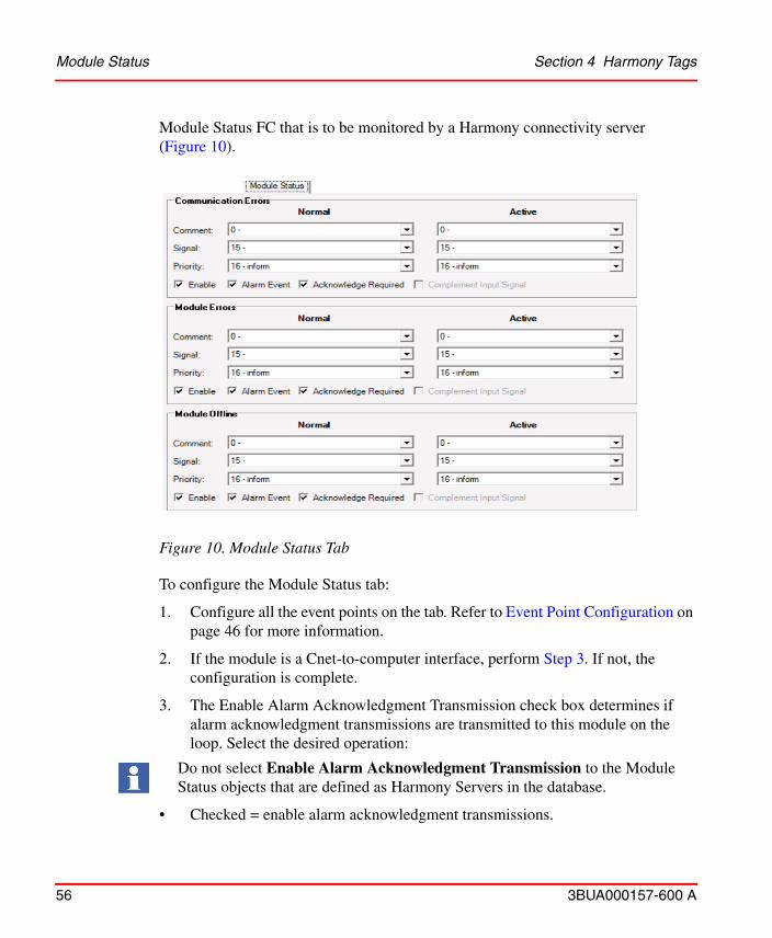
Module Status Section 4 Harmony Tags
56 3BUA000157-600 A
Module Status FC that is to be monitored by a Harmony connectivity server (Figure 10).
To configure the Module Status tab:
1. Configure all the event points on the tab. Refer to Event Point Configuration on page 46 for more information.
2. If the module is a Cnet-to-computer interface, perform Step 3. If not, the configuration is complete.
3. The Enable Alarm Acknowledgment Transmission check box determines if alarm acknowledgment transmissions are transmitted to this module on the loop.
Do not select Enable Alarm Acknowledgment Transmission to the Module Status objects that are defined as Harmony Servers in the database.
Select the desired operation:
• Checked = enable alarm acknowledgment transmissions.
Figure 10. Module Status Tab

Section 4 Harmony Tags Multi State Device Driver Tab
3BUA000157-600 A 57
• Cleared = disable alarm acknowledgment transmissions.
Multi State Device Driver TabThe Multi State Device Driver (MSDD) tag accesses information provided by a MSDD FC (refer to Table 8). The MSDD FC provides a means of controlling field equipment (variable speed motor) or control schemes that have more than one control mode. The MSDD block provides four state controls with feedback. Two control inputs or an operator input selects one of four output masks for control action. The MSDD tab of the MSDD tag object configures the MSDD FC that is to be monitored by the Harmony connectivity server (Figure 11).
To configure the MSDD tab:
1. Configure the output state and the state change event points. Refer to Event Point Configuration on page 46 for more information.
2. Set the normal and the active signal texts for the first feedback state by selecting one from the pick list.
TC04569A
Figure 11. MSDD Tab
PhaseX Tab Section 4 Harmony Tags
58 3BUA000157-600 A
3. If reverse logic is to be used for this tag (zero is active) enable complement input signal.
4. Repeat Step 2 through Step 3 for the remaining feedback states.
5. Configure the logic state descriptor zero through three by selecting a logic descriptor from the pick list.
PhaseX TabThe PhaseX tag accesses information provided by a phase execution FC (refer to Table 8). The phase execution FC provides the execution environment for a Batch 90 program that is interfaced to Batch Management or BDM software. A Batch 90 program is comprised of all the phases that can be run on a specific class of equipment. Recipes define the order in which the Batch 90 phases are executed (the procedure) and the specific formulation values such as target flow rates, temperatures and times. The PhaseX tab of the PhaseX tag object configures the phase execution FC that is to be monitored by the Harmony connectivity server (Figure 12).
To configure the PhaseX tab:
1. Configure the system fault, user defined fault, and the user defined message event points. Refer to Event Point Configuration on page 46 for more information.
2. When handshaking is enabled the block uses fast reporting max. time value (in seconds) for exception reports until a confirmation is received by the block. If handshaking is disabled the block uses slow reporting max. time value (in seconds) to report new values.
3. Set the fast reporting max. time. The fast reporting max. time is the time value used to monitor exception reports when handshaking is enabled.
Set the slow reporting max. time. The slow reporting max. time is the time value used to monitor exception reports when handshaking is disabled.
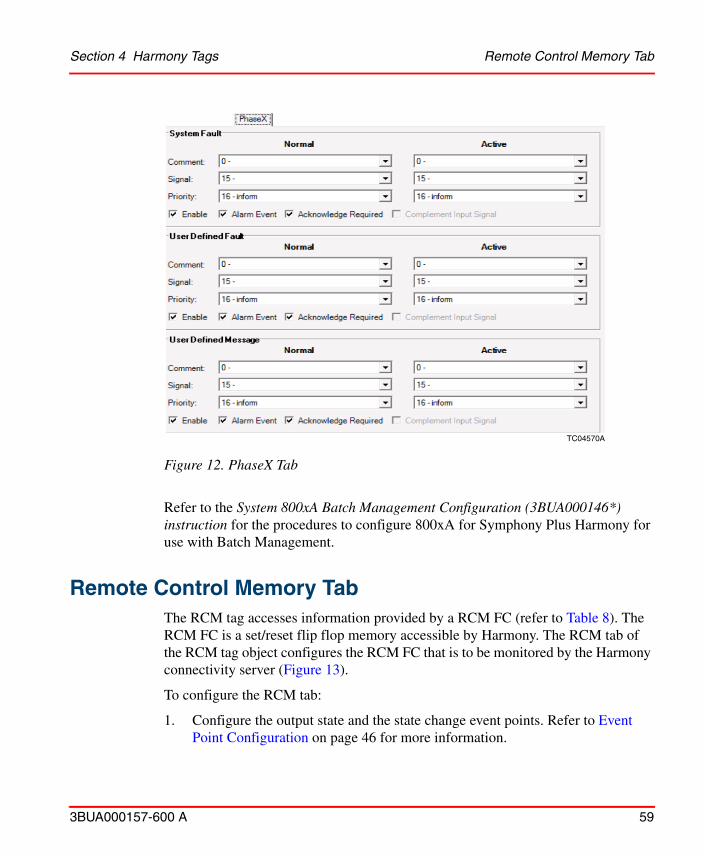
Figure 12. PhaseX Tab
TC04570A
Section 4 Harmony Tags Remote Control Memory Tab
3BUA000157-600 A 59
Refer to the System 800xA Batch Management Configuration (3BUA000146*) instruction for the procedures to configure 800xA for Symphony Plus Harmony for use with Batch Management.
Remote Control Memory TabThe RCM tag accesses information provided by a RCM FC (refer to Table 8). The RCM FC is a set/reset flip flop memory accessible by Harmony. The RCM tab of the RCM tag object configures the RCM FC that is to be monitored by the Harmony connectivity server (Figure 13).
To configure the RCM tab:
1. Configure the output state and the state change event points. Refer to Event Point Configuration on page 46 for more information.
Remote Motor Control Block Tab Section 4 Harmony Tags
60 3BUA000157-600 A
2. Use the pick lists to select the normal and the active signal texts for the first
feedback state.
3. If reverse logic is to be used for this tag (zero is active) enable complement input signal.
Remote Motor Control Block TabThe RMCB tag accesses information provided by a remote motor control FC (refer to Table 8). The remote motor control FC has two basic functions. First, it performs the logic necessary to control a Digital output. Second, it communicates the result of that logic to Harmony. The RMCB tab of the RMCB tag object configures the remote motor control FC that is to be monitored by the Harmony connectivity server (Figure 14).
Figure 13. RCM Tab
Section 4 Harmony Tags Remote Motor Control Block Tab
3BUA000157-600 A 61
To configure the RMCB tab:
1. Configure the output state and the state change event points. Refer to Event Point Configuration on page 46 for more information.
2. Use the pick lists to select the normal and the active signal texts for the first feedback state.
3. If reverse logic is to be used for this tag (zero is active), enable complement input signal.
4. Repeat Step 2 through Step 3 for the second feedback state.
5. Use the pick lists to select the normal and the active signal texts for the first permissive state.
6. If reverse logic is to be used for this tag (zero is active) enable complement input signal.
7. Repeat Step 5 through Step 6 for the second permissive state.
TC04572A
Figure 14. RMCB Tab
Remote Manual Set Constant Tab Section 4 Harmony Tags
62 3BUA000157-600 A
8. Use the pick list to select a text set index. The RMCB text sets are now defined in NLS Harmony RMCB Text Aspects on the INFI 90 System Definition Objects under Library Structure -> Symphony System Definitions. For more information, refer System Definition.
Remote Manual Set Constant TabThe Remote Manual Set Constant (RMSC) tag accesses information provided by a RMSC FC (refer to Table 8). The RMSC FC allows the value of a constant to be entered to the control scheme through Harmony. When the function block receives this command, an exception report is generated to notify the operator or computer that the value has changed. High and low limits can be set to guard against unreasonable values. The RMSC tab of the RMSC tag object configures the RMSC FC that is to be monitored by the Harmony connectivity server (Figure 15).
To configure the RMSC tab:
1. Set the high and the low range for the process variable. These are the maximum and minimum values allowed for the RMSC tag.
2. Use the pick list to select a configured engineering unit descriptor. The controller reports the index number that associates an engineering unit of measurement with this tag. A list of valid fixed and user defined engineering units can be viewed in the NLS Engineering Unit Aspect under the INFI90 System Definition Object.
3. Set the display format using the width (number of characters) and digits (number of decimal digits) controls. The syntax of this field is:Number of characters X 10 + number of decimal digits
TC04573A
Figure 15. RMSC Tab
The values set in Step 1 and Step 2 are configurable for initial value purposes only. They will be overwritten by values reported from the function block after startup.
Section 4 Harmony Tags Station Tab
3BUA000157-600 A 63
Station TabThe Station tag accesses information provided by a Station FC (refer to Table 8). There are three types of Stations, each controllable through a control station and Harmony. The types include basic, cascade, and ratio Stations. The Station tab of the Station tag object configures the Station FC that is to be monitored by the Harmony connectivity server (Figure 16).
TC04574A
Figure 16. Station Tab

Basic Section 4 Harmony Tags
64 3BUA000157-600 A
Basic
A basic Station generates a SP and provides manual/automatic transfers, control output adjustments in manual control mode, and SP adjustments in automatic control mode.
Cascade
A cascade Station provides the same functions as a basic Station plus an additional mode that allows the SP to be controlled by external input signal.
Ratio
A ratio Station provides the same functions as a basic Station, but differs from the cascade Station in its method of SP generation when in the ratio mode. A wild variable multiplied by a ratio adjustment factor (ratio index) determines the SP output when in ratio mode. The initial ratio index value is calculated by the Station to maintain the current SP output value when the Station is placed into the ratio mode. When in the ratio mode, the ratio index value is displayed in place of the SP value and can be adjusted (ramped up or down) by the operator to obtain the desired SP output.
Station control allows changing the mode, SP, ratio index and control output of a control Station by manipulating a control Station element. The control output value during startup is configurable.
To configure the Station tab:
1. Configure the low alarm and the high alarm event points. Refer to Event Point Configuration on page 46 for more information.
2. Set the alarm limits for the tag. The alarm limits trigger the high and the low alarm event points when the value goes outside the respective limit.
3. Set the high and low signal initial process values.
4. Use the pick list to select a configured engineering unit descriptor. The controller reports the index number that associates an engineering unit of measurement with this tag. A list of valid fixed and user defined engineering units can be viewed in the NLS Engineering Unit Aspect under the INFI90 System Definition Object.
Section 4 Harmony Tags Text Selector
3BUA000157-600 A 65
5. Set the display format using the width (number of characters) and digits (number of decimal digits) controls. The syntax of this field is:Number of characters X 10 + number of decimal digits
6. Configure the low deviation and the high deviation event points. Refer to Event Point Configuration on page 46 for more information.
7. Set the high and low signal control output values.
8. Use the pick list to select a configured engineering unit descriptor. The controller reports the index number that associates an engineering unit of measurement with this tag. A list of valid fixed and user defined engineering units can be viewed in the NLS Engineering Unit Aspect under the INFI90 System Definition Object.
9. Set the display format using the width (number of characters) and digits (number of decimal digits) controls. The syntax of this field is:Number of characters X 10 + number of decimal digits
The values set in Step 2 through Step 4 and Step 6 through Step 8 are configurable for initial value purposes only. They will be overwritten by values reported from the function block after startup.
10. Repeat Step 7 through Step 9 for the deviation limit and the SP.
11. Select a tune block by clicking the increment or decrement arrows beside the field. The tuning block is the function block to appear in the Block Details portion of a tuning display (normally a PID block). A valid entry is 1 to 31,998 and is for the block address of the function block providing the Station block input or any function block in the controller. This allows the tuning display to be requested without any further input.
Text SelectorThe Text Selector tag defines text strings that can be associated with status reported for DD, MSDD, and RMCB tags. These text strings can describe the good, bad, and waiting condition being reported by a Device Driver or MSDD function block and the good, alarm, and waiting condition being reported by a remote motor control function block. The conditions are exception reported by a PCU module.
Text Selector Section 4 Harmony Tags
66 3BUA000157-600 A
In the module, a Text Selector function block (FC 151) must be defined in the control configuration to reference a DD, MSDD, and RMCB function block. The Text Selector function block can also be configured as a standalone Text Selector.
Each Text Selector message defined in the Configuration Server has a message number. The Text Selector function block in the controller selects one of these messages by its number. The function block exception reports a message number and also a color and blink parameter. A Text Selector tag must be configured in Harmony to receive this information.
To configure a Text Selector tag, configure the Harmony tab to monitor the desired Text Selector function block (FC 151) in the Harmony control system configuration.
The text selector strings are defined in the NLS Text Selector Text Aspects under the INFI 90 System Definition Objects in the Library Structure.

3BUA000157-600 A 67
Section 5 Uploader
IntroductionThe Uploader is an Aspect of a Harmony OPC Server Network Object. The Uploader allows the Tag object configurations to be imported to and exported from the Aspect Directory in a .mdb format. The Harmony configuration data for import can be generated by offline Harmony engineering tools or exported from other 800xA for Symphony Plus Harmony systems.
To access the Uploader, open Plant Explorer, select Control Structure and then select the Harmony OPC Server Network Object.
ABB does not recommend making bulk configuration changes online. When bulk changes are made, it is recommended that online change notifications are disabled. Refer to Online Change Notifications for details on disabling online changes. Each system may exhibit different update performance. ABB recommends disabling online changes if more than 100 Tags are being added, updated or removed.
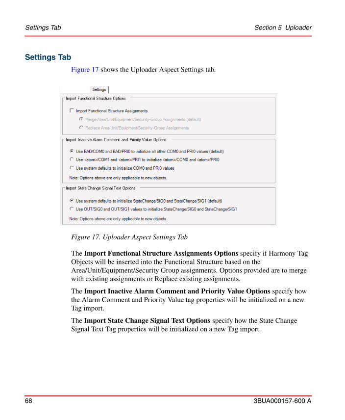
Settings Tab Section 5 Uploader
68 3BUA000157-600 A
Settings Tab
Figure 17 shows the Uploader Aspect Settings tab.
The Import Functional Structure Assignments Options specify if Harmony Tag Objects will be inserted into the Functional Structure based on the Area/Unit/Equipment/Security Group assignments. Options provided are to merge with existing assignments or Replace existing assignments.
The Import Inactive Alarm Comment and Priority Value Options specify how the Alarm Comment and Priority Value tag properties will be initialized on a new Tag import.
The Import State Change Signal Text Options specify how the State Change Signal Text Tag properties will be initialized on a new Tag import.
Figure 17. Uploader Aspect Settings Tab
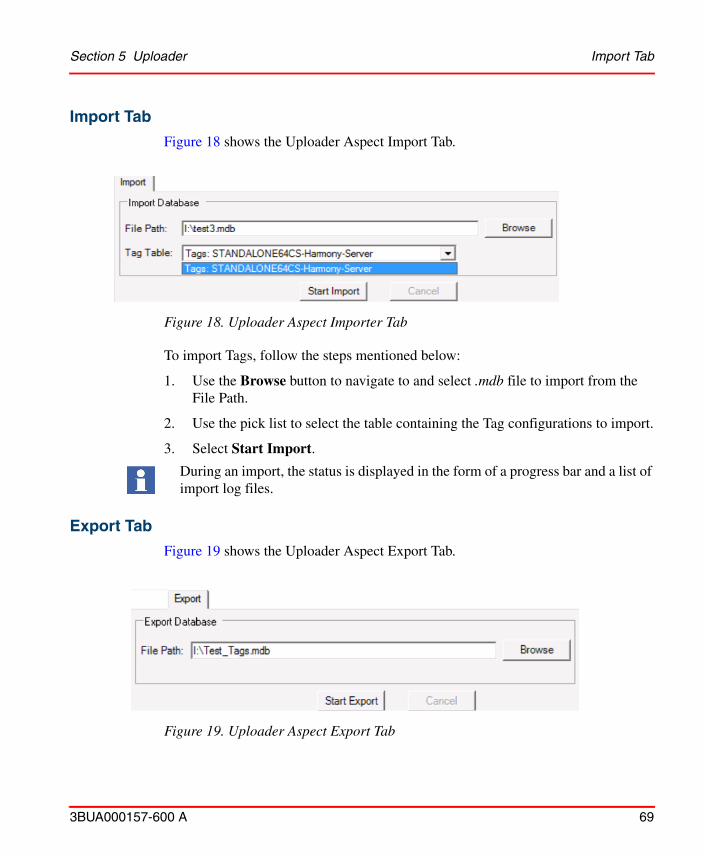
Section 5 Uploader Import Tab
3BUA000157-600 A 69
Import Tab
Figure 18 shows the Uploader Aspect Import Tab.
To import Tags, follow the steps mentioned below:
1. Use the Browse button to navigate to and select .mdb file to import from the File Path.
2. Use the pick list to select the table containing the Tag configurations to import.
3. Select Start Import.
During an import, the status is displayed in the form of a progress bar and a list of import log files.
Export Tab
Figure 19 shows the Uploader Aspect Export Tab.
Figure 18. Uploader Aspect Importer Tab
Figure 19. Uploader Aspect Export Tab
Export Tab Section 5 Uploader
70 3BUA000157-600 A
To export Tags, follow the steps mentioned below:
1. Use the Browse button to navigate to and specify the location and name of the .mdb file to export to the File Path.
2. Select Start Export.
During an export, the status is displayed in the form of a progress bar and a list of export log files.
There is no provision to selectively import or export Tags. All data in an mdb file will be imported using the import functionality. Likewise, all nodes in the Control Structure will be exported using the export functionality. In addition, the NLS Text Definitions under Library Structure->Symphony System Definition Objects will be exported.
3BUA000157-600 A 71
Section 6 SOE Reporting
IntroductionThis section describes the operation and configuration of SOE Reports. The hardware and software configurations for both distributed SOE Reports and Rochester SOE Reports are explained.
DescriptionHarmony SOE reporting is intended for use by plant personnel to closely monitor critical Digital points where the sequence of state changes for points or groups of points must be known in the most exacting ways possible. SOE reporting lists all Digital state transitions in time order and with one millisecond resolution.
The SOE log data can originate in an ABB Distributed SOE system (DSOE) or in a Rochester Instrument Systems SOE Recorder (Rochester SER). The SOE reporting system can interface with a SOE (IMSEM01) module containing fixed blocks 5000 and 5001 or with a Harmony bridge controller (BRC-100 or BRC-200) or a multifunction processor (MFP) containing FC 99 (SOE log) blocks.
In both cases, SOE trigger tags can be configured for the blocks to monitor SOE trigger points in the control system. The SOE reporting system then collects SOE Reports whenever the trigger points indicate the presence of SOE data.
Specific FeaturesThe following are features of SOE reporting on Harmony:
• One millisecond resolution on change of state timestamps.
• Each controller/SER recorder pair in a Rochester SOE architecture can have multiple FC 99 SOE Report types.

Standard Section 6 SOE Reporting
72 3BUA000157-600 A
• Build SOE Reports from the data that it has gathered through communications with hAPI, using preconfigured report formats.
• Five types of SOE Reports/triggering:
Standard
In a standard log, any SOE point state change will result in a timestamped SOE Report for this point. This SOE log will be stored in the controller (FC 99) or in the IMSEM01 module (DSOE) for the length of time specified within the corresponding block (the aging time). This log must be read in by the SOE reporting system before the aging time expires.
Summary
A summary log contains a report of all timestamped SER points which are not in normal state (inactive, deleted from scan, or in SOE alarm). This report can be demanded by changing the RCM block output of the corresponding IMSEM01 block 5001 or FC 99 in the controller (the summary trigger point) from zero to one.
Pre-fault
SER point state changes are stored by a designated quantity or time period (50 events prior to trigger; 10 minutes prior to trigger). They are then reported, in ascending time order, when the pre-fault trigger is changed from zero to one by the operator (Rochester SOE reporting only).
Post-fault
SER point state changes are reported only after the post-fault trigger is changed from zero to one by the user. The points will continue to be reported until the postfault trigger reverts back to zero. The SOE system must remove these reports from the SOE or DSOE system before its aging time expires (Rochester SOE reporting only).
Snapshot
Snapshot reports will have points listed in ascending numerical order, but only after the snapshot trigger is changed from zero to one by the user. Snapshot points can be
1. DSOE reporting supports only two SOE log types, standard (through IMSEM01 block 5000) and summary (through IMSEM01 block 5001).
2. Snapshot reports are not available on all Rochester SOE reporters. Consult the documentation of the Rochester SER hardware in this case.
3. If SOE reporting is running on a pair of Connectivity servers, SOE Reports will be identically collected on both Servers. Refer to SOE Reporting and Redundancy on page 74 for more information.
Section 6 SOE Reporting Trigger Tag Monitoring
3BUA000157-600 A 73
designated in groups such as those which are normal, those which are deleted from scan, etc. (Rochester SOE reporting only).
Trigger Tag MonitoringTrigger points enable SOE Masters (SEM) and multifunction processors (MFP) to notify the SOE system that SOE data is available for collection.
For each active SOE log report, the collection of SOE data is governed by using the SOE Report tag to monitor the trigger output values of blocks 5000 and 5001 of a SEM module in a DSOE system, or a FC 99 block in an MFP module for a Rochester SOE system.
The SOE data collection by the Harmony connectivity server system is started automatically when or shortly after the trigger tag goes into a trigger state. When an SOE Report is triggered, SOE events are read in from the SOE function block. When an SOE log is completed, it will be stored in an internal queue and the REPORTREAD property is set to one to trigger the report system. Upon resetting of the REPORTREAD property to zero or the time duration exceeding the defined cache time, the report will be removed from the head of the queue.
SOE Reports CollectionWhen REPORTREAD property is triggered for a configured SOE Report object, the report formats the SOE event log data into a predefined SOE Report, and resets the REPORTREAD property to zero. The report system makes the SOE data available for the user to view.
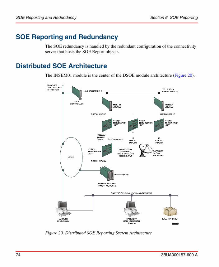
SOE Reporting and Redundancy Section 6 SOE Reporting
74 3BUA000157-600 A
SOE Reporting and RedundancyThe SOE redundancy is handled by the redundant configuration of the connectivity server that hosts the SOE Report objects.
Distributed SOE ArchitectureThe INSEM01 module is the center of the DSOE module architecture (Figure 20).
Figure 20. Distributed SOE Reporting System Architecture
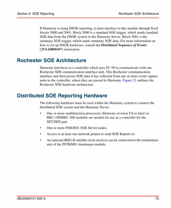
Section 6 SOE Reporting Rochester SOE Architecture
3BUA000157-600 A 75
If Harmony is using DSOE reporting, it must interface to this module through fixed blocks 5000 and 5001. Block 5000 is a standard SOE trigger, which sends standard SOE data from the DSOE system to the Harmony Server. Block 5001 is the summary SOE trigger, which sends summary SOE data. For more information on how to set up DSOE hardware, consult the Distributed Sequence of Events (2VAA000844*) instruction.
Rochester SOE ArchitectureHarmony interfaces to a controller which uses FC 99 to communicate with one Rochester SER communication interface unit. This Rochester communication interface unit then passes SOE data it has collected from one or more event capture units to the controller, where they are passed to Harmony. Figure 21 outlines the Rochester SOE hardware architecture.
Distributed SOE Reporting HardwareThe following hardware must be used within the Harmony system to connect the distributed SOE system and the Harmony Server.
• One or more multifunction processors (firmware revision F.0 or later) or BRC-100/BRC-200 modules are needed for use as a controller for the SET/SED pair.
• One or more INSOE01 SOE Server nodes.
• Access to at least one network printer to send SOE Reports to.
• An optional IRIG-B satellite clock receiver can be connected to the termination unit of the INTKM01 timekeeper module.
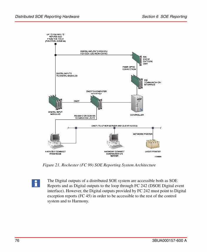
Distributed SOE Reporting Hardware Section 6 SOE Reporting
76 3BUA000157-600 A
Figure 21. Rochester (FC 99) SOE Reporting System Architecture
The Digital outputs of a distributed SOE system are accessible both as SOE Reports and as Digital outputs to the loop through FC 242 (DSOE Digital event interface). However, the Digital outputs provided by FC 242 must point to Digital exception reports (FC 45) in order to be accessible to the rest of the control system and to Harmony.

Section 6 SOE Reporting Rochester SOE Reporting Hardware
3BUA000157-600 A 77
Rochester SOE Reporting HardwareThe following hardware must be used within the Harmony system to connect the Rochester SOE system and the Harmony Server:
• A Rochester reporter consisting of one (or more) Rochester event capture units (ECU) and an Rochester SOE communication interface unit with one fiber optic communications board per event capture unit. The communication interface unit also needs a special ABB communications board, manufactured by Rochester Instrument Systems.
• One or more multifunction processors (firmware revision F.0 or later) or BRC-100/BRC-200 modules to contain FC 99 for the Rochester reporter.
• Access to at least one network printer for sending SOE Reports to.
• CRT terminal (VT100, WYSE50 or terminal emulation program/window) is needed for issuing ISM-1 commands to the Rochester communication interface unit if configuration of the Rochester SER system is required.
• Required termination units and cables to connect each of the modules. Refer to the product instructions for wiring diagrams.
The points collected by the Rochester system are only available to the system in the form of SOE Reports. If these points are needed in the process control system as Digital points, then these points must be physically wired into Digital input modules as well as the Rochester reporter. Include these points in calculations when determining the number of I/O modules required.
In order for the distributed SOE system to function properly, the function blocks in both the SOE module, as well as the module which serves as the SET/SED controller must be properly configured with SOE FCs. For more information concerning these particular FCs, refer to the Function Code Application Manual ((2VAA000844*)).

External Interfaces and Function Blocks Section 6 SOE Reporting
78 3BUA000157-600 A
External Interfaces and Function BlocksThe SOE reporting system requires the following interfaces:
• Each SOE log trigger tag must be specified as an SOE Report tag within the Harmony tag database, with its loop, node, module and block being the same as that of the corresponding fixed output blocks 5000 and 5001 within the SEM module or the corresponding FC 99 output block within a controller.
• SEM fixed output blocks 5000 and 5001 interface with the distributed SOE system to input millisecond timestamp distributed SOE events. Block 5000 is used for collecting standard SOE events. Block 5001 is used for collecting summary SOE events upon command by using a point display or an SOE Report faceplate to set this SOE Report tag to one. These SEM blocks are not configurable.
• A Rochester SOE system requires that each controller have at least one FC 99 trigger block to accept SOE Reports from the Rochester equipment or Digital input modules.
• FC 99 uses communications protocol necessary to interface with a special ABB communications board (manufactured by Rochester Instrument Systems) within the Rochester communication interface unit. This protocol is built into the firmware of the controller itself.
• Digital tags must be configured in the tag database for all input field points used by the SOE system.
SOE ObjectsThe SOE Reports are configured with SOE recorder and SOE Report objects. Digital points are assigned to the SOE recorders. The recorders are then assigned to the SOE Report objects.
The SOE Report object is configured for each SOE Report that is to be done by Harmony. An SOE Report tag is used for triggering SOE Reports. Each SOE Report object has an SOE recorder associated to it.
The report object is triggered by the REPORTREAD property. The Harmony report system will create the report from the data collected from the connectivity server.
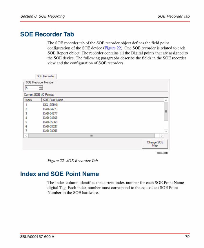
Section 6 SOE Reporting SOE Recorder Tab
3BUA000157-600 A 79
SOE Recorder TabThe SOE recorder tab of the SOE recorder object defines the field point configuration of the SOE device (Figure 22). One SOE recorder is related to each SOE Report object. The recorder contains all the Digital points that are assigned to the SOE device. The following paragraphs describe the fields in the SOE recorder view and the configuration of SOE recorders.
Index and SOE Point NameThe Index column identifies the current index number for each SOE Point Name digital Tag. Each index number must correspond to the equivalent SOE Point Number in the SOE hardware.
TC02494B
Figure 22. SOE Recorder Tab

Change (Create) SOE Map Section 6 SOE Reporting
80 3BUA000157-600 A
Change (Create) SOE MapThis button when clicked, brings up a display containing the valid digital Tag names available for an assignment. In the case of a newly created SOE Recorder Object, the button is labeled Create SOE Map.
SOE Digital Point AssociationsFigure 23 displays the assignment of SOE points and their indices:
To assign the available points to SOE Points, select the check boxes for the desired points in the Available SOE I/O Points window, and then select the >> button.
The indices can be changed by selecting the index and changing its value.
Once the new indices have been assigned, select the Validate Indexes button.
Figure 23. SOE Point Names and Indices
The valid index range is 1 to 1,500. Any value entered outside this range will be ignored and the index reverts to its previously assigned value.

Section 6 SOE Reporting SOE Digital Point Associations
3BUA000157-600 A 81
All index numbers must be unique in the SOE Recorder. If non-unique numbers are found, a message box will display indicating this.
Once all SOE Point index numbers have been validated, the Cancel and Apply buttons are enabled, and the changes may be applied.
To remove I/O points from the Current SOE I/O Points list:
a. Click Change SOE Map, select the check boxes for the points to remove in the Current SOE I/O Points window, and then select the << button.
b. Select Validate Indexes, and then click Apply to save the changes.
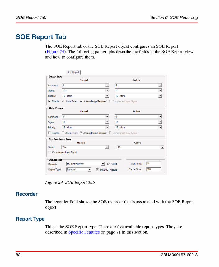
SOE Report Tab Section 6 SOE Reporting
82 3BUA000157-600 A
SOE Report TabThe SOE Report tab of the SOE Report object configures an SOE Report (Figure 24). The following paragraphs describe the fields in the SOE Report view and how to configure them.
Recorder
The recorder field shows the SOE recorder that is associated with the SOE Report object.
Report Type
This is the SOE Report type. There are five available report types. They are described in Specific Features on page 71 in this section.
Figure 24. SOE Report Tab

Section 6 SOE Reporting Wait Time
3BUA000157-600 A 83
If the INSMEM01 check box is enabled, only the snapshot and summary report types are available.
Wait Time
The wait time applies only to SOE Reports of type standard and post-fault. This is the time difference between when the state of the trigger tag changes from zero to one (when the SOE system in the control system begins filling its internal buffer with new SOE Reports) and when the SOE reporting system begins collecting these reports from the control system.
Active
The Active check box indicates whether an SOE Report is active and being monitored and collected by the SOE system, or if the report is inactive. To configure the SOE Report object:
1. Configure the output state and the state change event points. Refer to Section 4, Harmony Tags for more information.
2. Use the pick list to select the normal and the active signal text for the first feedback state.
3. If reverse logic is to be used for this tag (zero is active) enable complement input signal.
4. Select an SOE recorder to use for the report. Use the pick list to select an SOE Recorder to use for the report.
5. Enable or disable the IMSEM01 Module option, and then select the Report type.
6. Click on the Active box to toggle this report from inactive to active, or from active to inactive.
7. Set a wait time. The default is 30 seconds.
The wait time must be much less than the aging time configured in the SOE system in the control system for this trigger point. Otherwise, valuable SOE data may be aged out of the internal buffer of the SOE system and be lost before it is collected by Harmony.
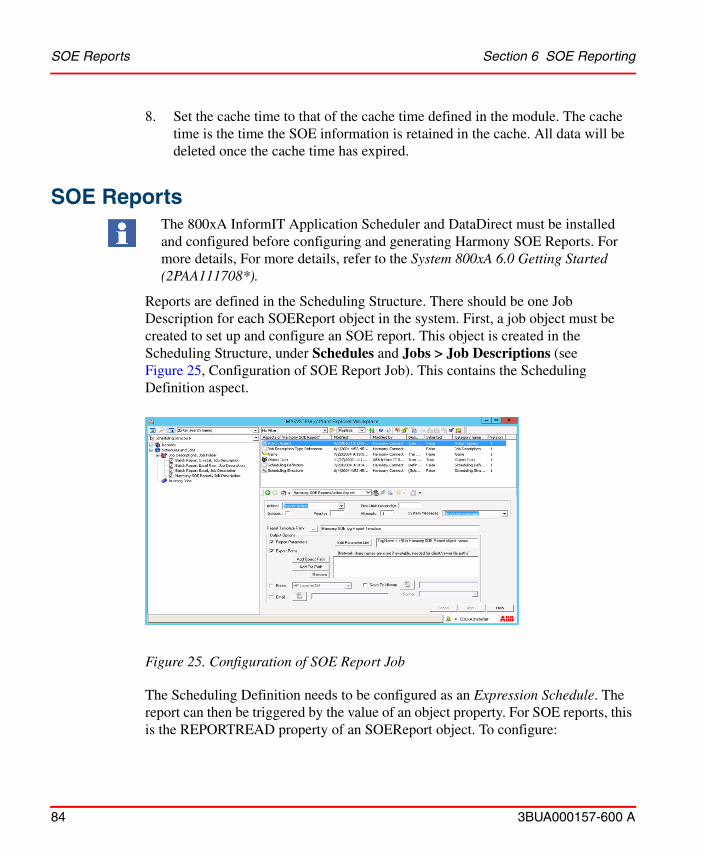
SOE Reports Section 6 SOE Reporting
84 3BUA000157-600 A
8. Set the cache time to that of the cache time defined in the module. The cache time is the time the SOE information is retained in the cache. All data will be deleted once the cache time has expired.
SOE ReportsThe 800xA InformIT Application Scheduler and DataDirect must be installed and configured before configuring and generating Harmony SOE Reports. For more details, For more details, refer to the System 800xA 6.0 Getting Started (2PAA111708*).
Reports are defined in the Scheduling Structure. There should be one Job Description for each SOEReport object in the system. First, a job object must be created to set up and configure an SOE report. This object is created in the Scheduling Structure, under Schedules and Jobs > Job Descriptions (see Figure 25, Configuration of SOE Report Job). This contains the Scheduling Definition aspect.
The Scheduling Definition needs to be configured as an Expression Schedule. The report can then be triggered by the value of an object property. For SOE reports, this is the REPORTREAD property of an SOEReport object. To configure:
Figure 25. Configuration of SOE Report Job
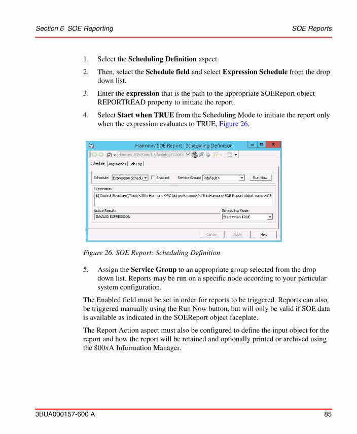
Section 6 SOE Reporting SOE Reports
3BUA000157-600 A 85
1. Select the Scheduling Definition aspect.
2. Then, select the Schedule field and select Expression Schedule from the drop down list.
3. Enter the expression that is the path to the appropriate SOEReport object REPORTREAD property to initiate the report.
4. Select Start when TRUE from the Scheduling Mode to initiate the report only when the expression evaluates to TRUE, Figure 26.
Figure 26. SOE Report: Scheduling Definition
5. Assign the Service Group to an appropriate group selected from the drop down list. Reports may be run on a specific node according to your particular system configuration.
The Enabled field must be set in order for reports to be triggered. Reports can also be triggered manually using the Run Now button, but will only be valid if SOE data is available as indicated in the SOEReport object faceplate.
The Report Action aspect must also be configured to define the input object for the report and how the report will be retained and optionally printed or archived using the 800xA Information Manager.
SOE Reports Section 6 SOE Reporting
86 3BUA000157-600 A
For long-term archival of completed reports, the system must include the 800xA Information Manager that is configured to archive report data.
Before reports can be historized, you must configure a Report Log using an appropriate log access name for each report type. The report log access name will then be used to identify the log to send archived reports to.
6. Select the Action Aspect (Figure 25) to configure the report action parameters. Select Report Action from the Action drop down list. If desired, a timeout value may be specified, but in most situations the default values for the Time Limit, Isolated, Priority, Attempts and System Messages should be used.
Refer to the System 800xA Information Management Configuration (3BUF001092*) instruction for procedures on how to configure this.

Section 6 SOE Reporting SOE Reports
3BUA000157-600 A 87
7. Next, select the report template to be used. To export a report, click the Report Template Path button and select the Harmony SOE log template. The location of this template is shown in Figure 27, Harmony SOE Log Template Location.
Figure 27. Harmony SOE Log Template Location
8. There is only one Report Parameter to configure, the SOEReport object. Click Add Parameter and enter 'TagName' in the Name field and the SOEReport object name in the Value field.
9. Double click the existing entry, 'TagName=', to change these values for your system.

SOE Reports Section 6 SOE Reporting
88 3BUA000157-600 A
10. Reports are saved on the local system by exporting. Select the Export Paths option.
11. Then select Add Object Path to save the reports in the Aspect system. These will be retained under Reports> folder Name (in this example, SoeReport Folder). These may then be later reviewed and/or printed by any clients on the system that have Microsoft Excel installed locally.
12. If required, output reports can also be saved to a local file folder. Select Add File Path to configure the output folder and file name.
The print area is predefined in the Excel spreadsheet. This can be modified and saved in the template if required. This definition is used when the printer option is selected and configured in the Action Aspect, Figure 28.
Figure 28. SOE Report: Action Aspect
Section 6 SOE Reporting Configuring the Rochester SER
3BUA000157-600 A 89
13. To save the completed report in a long-term archive, select Save to History and select the appropriate report log name from the drop down list. Select .xls format to save in the correct format.
Refer to the System 800xA Information Management Data Access and Reports (3BUF001094*) instruction for procedures on how to configure this. Refer to the same instruction for more information on the scheduler and reports.
Configuring the Rochester SERA Rochester SOE architecture may require custom configuration to suit specific needs. Configure Rochester reporters using Rochester ISM-1 commands. These are outlined in the Rochester Integrated System Monitor instruction. To use ISM-1 commands, a CRT terminal (VT100 or WYSE50) is required. Complete installation instructions of the ISM-1 system are provided in the Rochester Installation instruction.
SOE Reports of report type pre-fault and post-fault, which are available only with FC 99, require that the Rochester communication interface unit be specially configured, to enable it to send pre-fault and post-fault SOE events to Harmony. Each of these report types need a Boolean trigger equation to determine if and when pre-fault or post-fault trigger situations exist. Also, Rochester SER Digital points must be specifically designated as pre-fault points and post-fault points in order to show up in SOE Reports of these particular types.
Rochester ISM-1 Commands to Configure Pre-fault SOE Reports
For pre-fault SOE Reports, use the ISM-1 command pretrig to configure the pre-trigger equation. For example, the pre-trigger can be tripped by Rochester point five going into alarm (a zero to one logic state transition) simply by entering:
pretrig 5
Then, to designate Rochester SER Digital points to be pre-fault points, use the ISM-1 command:
prepoints s <pointnumbers>
Rochester ISM-1 Commands to Configure Post-Fault SOE Reports Section 6 SOE Reporting
90 3BUA000157-600 A
For example, to pre-fault designate Rochester SER Digital points 21 to 30 inclusive, plus 48, enter:
prepoints s 21-30 48
The Rochester SER is now ready to report pre-fault reports. In this example, points 21 through 30, plus point 48, are the only Digital points that would show up in the SER pre-fault SOE Reports.
To remove the pre-fault designation on points 16 through 20, enter:
prepoints r 16-20
Rochester ISM-1 Commands to Configure Post-Fault SOE Reports
For post-fault SOE Reports, use the ISM-1 command posttrig to configure the post-trigger equation. For example, the post-trigger can be tripped by Rochester point three going into alarm (zero to one logic state transition) simply by entering:
posttrig 3
Then, to designate Rochester SER Digital points to be post-fault points, use the ISM-1 command:
postpoints s <pointnumbers>
For example, to post-fault designate Rochester SER Digital points one to 10 inclusive, plus 16, enter:
postpoints s 1-10 16
The Rochester SER is now ready to report post-fault reports. In this example, points one through 10, plus point 16 are the only Digital points that would show up in the SER post-fault SOE Reports.
To remove the pre-fault designation on points six through ten, enter:
postpoints r 6-10
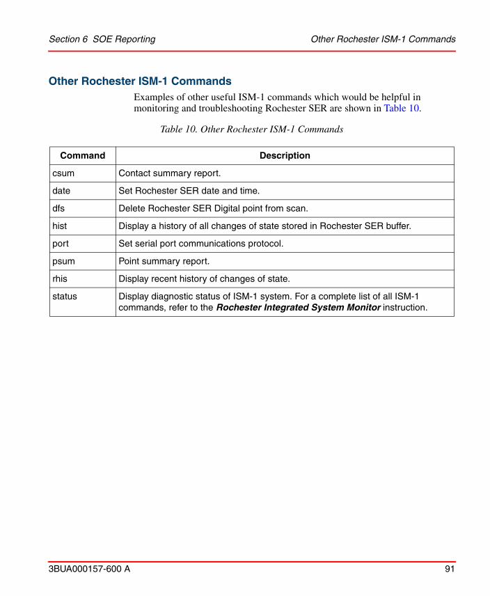
Section 6 SOE Reporting Other Rochester ISM-1 Commands
3BUA000157-600 A 91
Other Rochester ISM-1 CommandsExamples of other useful ISM-1 commands which would be helpful in monitoring and troubleshooting Rochester SER are shown in Table 10.
Table 10. Other Rochester ISM-1 Commands
Command Description
csum Contact summary report.
date Set Rochester SER date and time.
dfs Delete Rochester SER Digital point from scan.
hist Display a history of all changes of state stored in Rochester SER buffer.
port Set serial port communications protocol.
psum Point summary report.
rhis Display recent history of changes of state.
status Display diagnostic status of ISM-1 system. For a complete list of all ISM-1 commands, refer to the Rochester Integrated System Monitor instruction.

Other Rochester ISM-1 Commands Section 6 SOE Reporting
92 3BUA000157-600 A
3BUA000157-600 A 93
Section 7 System Definition
IntroductionThis section describes the configuration of the Symphony System Definition Object NLS aspects.
Symphony System Definition ObjectsText configuration data for Harmony Tag Objects is maintained in NLS Aspects on the Symphony System Definition Objects located in the Library structure. Multiple Symphony System Definitions Objects can be created. However, only one can be assigned to a specific Harmony OPC Server Network Object.
The following NLS aspects are provided:
• NLS Alarm Priority Text
• NLS Engineering Unit Descriptors
• NLS Event Comments
• NLS Harmony PhaseX Fault Codes
• NLS Harmony PhaseX Substitutable Text
• NLS Harmony RMCB Text
• NLS Harmony Substitutable Text
• NLS Logic State Descriptors
• NLS OPC Quality Text
• NLS Symphony Substitutable Text
• NLS Text Selector Text

NLS Alarm Priority Text Section 7 System Definition
94 3BUA000157-600 A
NLS Alarm Priority Text
An alarm priority can be represented by text. There are 17 alarm priorities. Each priority can be assigned different priority text including both active and normal state events. The alarm priorities are shown in Table 11.
NLS Engineering Unit Descriptors
Engineering unit descriptors (EUD) relate to Analog signals in the control system. They describe the unit of measurement (DEG F, GPM, AMPS, LB/HR) for the Analog signal.
A list of common engineering units is provided. Theoretically, an unlimited number of engineering unit descriptors can be defined in the database; although, zero through 15 are fixed.
Only the default alarm priorities are available. No others can be added.
Table 11. Alarm Priorities
Priority Descriptor Priority Descriptor
0 Priority Error! 9 WARNING
1 DIRE 10 warning
2 dire 11 ADVISE
3 CRUCIAL 12 advise
4 crucial 13 NOTIFY
5 CRITICAL 14 notify
6 critical 15 INFORM
7 ALERT 16 inform
8 alert — —
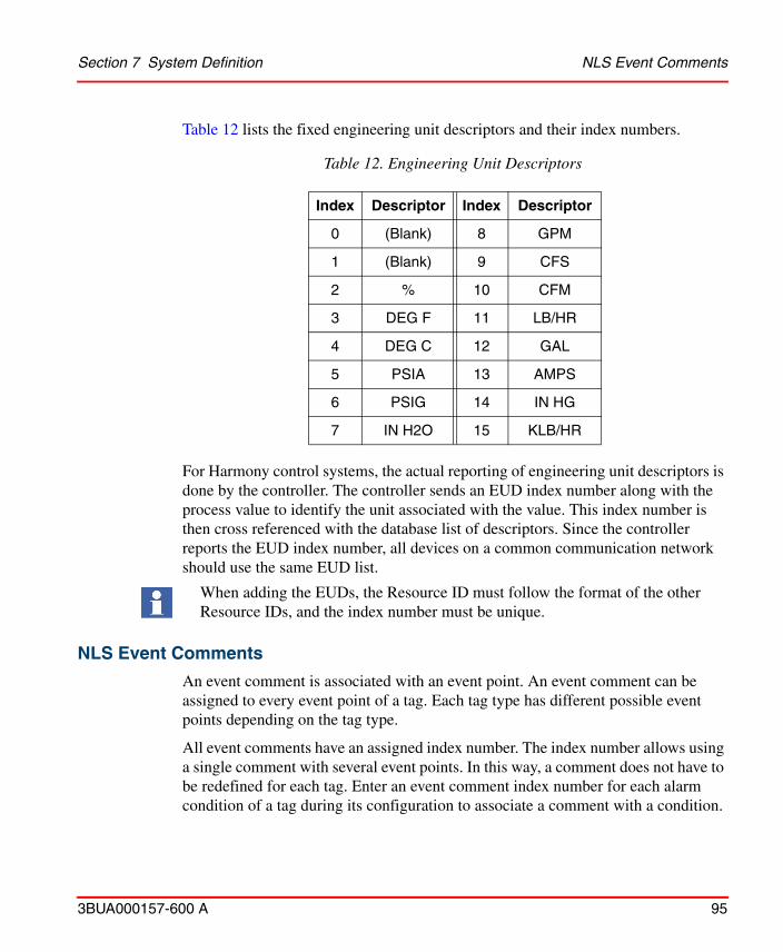
Section 7 System Definition NLS Event Comments
3BUA000157-600 A 95
Table 12 lists the fixed engineering unit descriptors and their index numbers.
For Harmony control systems, the actual reporting of engineering unit descriptors is done by the controller. The controller sends an EUD index number along with the process value to identify the unit associated with the value. This index number is then cross referenced with the database list of descriptors. Since the controller reports the EUD index number, all devices on a common communication network should use the same EUD list.
NLS Event Comments
An event comment is associated with an event point. An event comment can be assigned to every event point of a tag. Each tag type has different possible event points depending on the tag type.
All event comments have an assigned index number. The index number allows using a single comment with several event points. In this way, a comment does not have to be redefined for each tag. Enter an event comment index number for each alarm condition of a tag during its configuration to associate a comment with a condition.
Table 12. Engineering Unit Descriptors
Index Descriptor Index Descriptor
0 (Blank) 8 GPM
1 (Blank) 9 CFS
2 % 10 CFM
3 DEG F 11 LB/HR
4 DEG C 12 GAL
5 PSIA 13 AMPS
6 PSIG 14 IN HG
7 IN H2O 15 KLB/HR
When adding the EUDs, the Resource ID must follow the format of the other Resource IDs, and the index number must be unique.
To successfully import a database into Composer, be sure to modify any negative comment indices assigned by Harmony. Composer does not support comment indices less than zero.
NLS Harmony PhaseX Fault Codes Section 7 System Definition
96 3BUA000157-600 A
NLS Harmony PhaseX Fault Codes
This is an error code returned by the PhaseX FC. It describes what went wrong with a particular phase.
NLS Harmony PhaseX Substitutable Text
Harmony PhaseX Substitutable Text defines Harmony PhaseX related text strings with default values that can be substituted by the user.
NLS Harmony RMCB Text
Remote Motor Control Block (RMCB) Text defines text sets that contain text strings for remote motor control Function Blocks. The Function Block can report any of ten different text strings that identify its current operation. These error codes are reported to identify the condition that caused a bad start of a device. An RMCB tag must be configured for Harmony to receive an exception report.
Remote Motor Control Block Text Tab
Remote Motor Control Block (RMCB) Text defines text sets that contain text strings for remote motor control Function Blocks. The Function Block can report any of ten different text strings that identify its current operation. These error codes are reported to identify the condition that caused a bad start of a device. An RMCB tag must be configured for Harmony to receive an exception report.
Error codes and statuses reported include:
• No error.• Stopped.• Interlock one.• Interlock two.
Refer to the System 800xA Batch Management Configuration (3BUA000146*) instruction for the procedures to configure 800xA for Symphony Plus Harmony for use with Batch Management.
Section 7 System Definition NLS Harmony Substitutable Text
3BUA000157-600 A 97
• Interlock three.• Interlock four.• Feedback one = 0.• Feedback two = 0.• Feedback one = 1.• Feedback two = 1.
The interlock codes indicate not set or logic zero conditions for each of four interlocks.
Each error code text set has an assigned number. Up to 100 sets can be defined numbered zero to 99. A text set field for an RMCB tag selects which text set is to be used for the tag. The specific text string that displays depends on the error code returned in an exception report from the RMCB block.
NLS Harmony Substitutable Text
Harmony Substitutable Text defines Harmony tag related text strings with default values that can be substituted by the user.
NLS Logic State Descriptors
Logic state descriptors (LSD) describe logic states for Digital signals. These descriptors show the current logic state (on or off, zero or one, run or stop, or closed or open) of a device. A descriptor follows a tag throughout all Harmony functions after being defined for a tag.
A list of common logic state descriptors is provided. Theoretically, an unlimited number of logic state descriptors can be defined in the database; although, zero through 15 are fixed. Table 13 lists the fixed logic state descriptors and their index numbers.
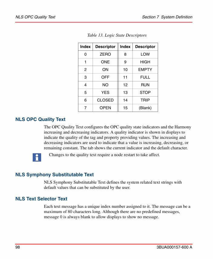
NLS OPC Quality Text Section 7 System Definition
98 3BUA000157-600 A
NLS OPC Quality Text
The OPC Quality Text configures the OPC quality state indicators and the Harmony increasing and decreasing indicators. A quality indicator is shown in displays to indicate the quality of the tag and property providing values. The increasing and decreasing indicators are used to indicate that a value is increasing, decreasing, or remaining constant. The tab shows the current indicator and the default character.
NLS Symphony Substitutable Text
NLS Symphony Substitutable Text defines the system related text strings with default values that can be substituted by the user.
NLS Text Selector Text
Each text message has a unique index number assigned to it. The message can be a maximum of 80 characters long. Although there are no predefined messages, message 0 is always blank to allow displays to show no message.
Table 13. Logic State Descriptors
Index Descriptor Index Descriptor
0 ZERO 8 LOW
1 ONE 9 HIGH
2 ON 10 EMPTY
3 OFF 11 FULL
4 NO 12 RUN
5 YES 13 STOP
6 CLOSED 14 TRIP
7 OPEN 15 (Blank)
Changes to the quality text require a node restart to take affect.
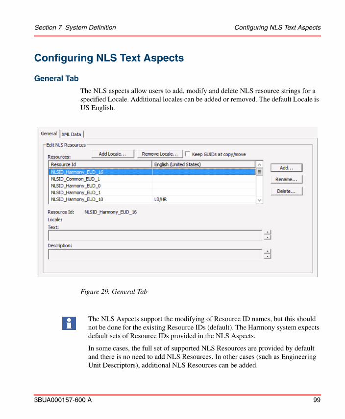
Section 7 System Definition Configuring NLS Text Aspects
3BUA000157-600 A 99
Configuring NLS Text Aspects
General Tab
The NLS aspects allow users to add, modify and delete NLS resource strings for a specified Locale. Additional locales can be added or removed. The default Locale is US English.
Figure 29. General Tab
The NLS Aspects support the modifying of Resource ID names, but this should not be done for the existing Resource IDs (default). The Harmony system expects default sets of Resource IDs provided in the NLS Aspects.
In some cases, the full set of supported NLS Resources are provided by default and there is no need to add NLS Resources. In other cases (such as Engineering Unit Descriptors), additional NLS Resources can be added.
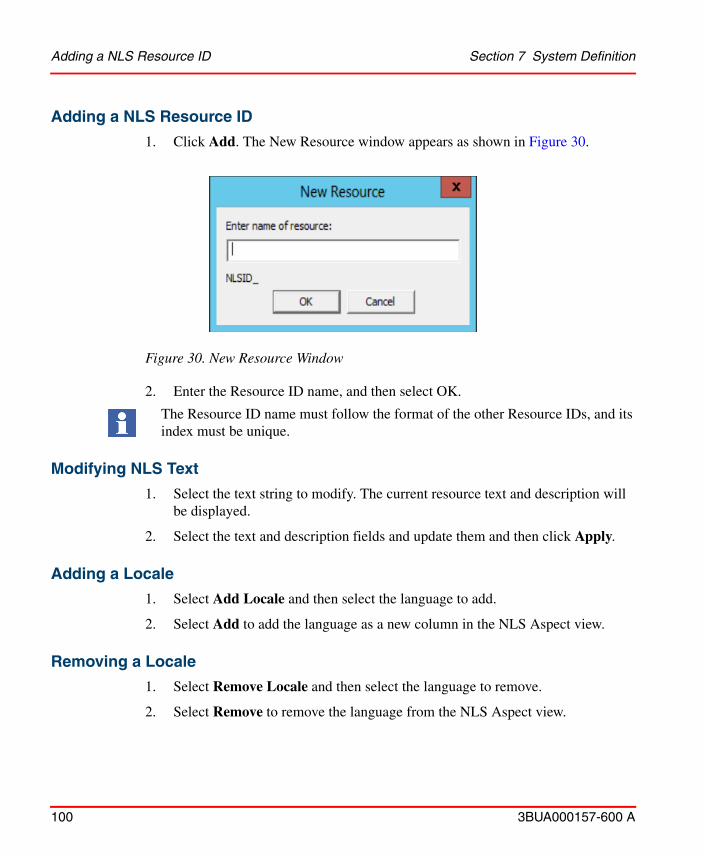
Adding a NLS Resource ID Section 7 System Definition
100 3BUA000157-600 A
Adding a NLS Resource ID
1. Click Add. The New Resource window appears as shown in Figure 30.
Figure 30. New Resource Window
2. Enter the Resource ID name, and then select OK.
The Resource ID name must follow the format of the other Resource IDs, and its index must be unique.
Modifying NLS Text
1. Select the text string to modify. The current resource text and description will be displayed.
2. Select the text and description fields and update them and then click Apply.
Adding a Locale
1. Select Add Locale and then select the language to add.
2. Select Add to add the language as a new column in the NLS Aspect view.
Removing a Locale
1. Select Remove Locale and then select the language to remove.
2. Select Remove to remove the language from the NLS Aspect view.

Section 7 System Definition XML Data Tab
3BUA000157-600 A 101
XML Data Tab
NLS Aspects support extracting and loading of the NLS resource text strings in a .xml format.
Extraction
1. Select Extract to launch the Select File to Extract window.
2. Navigate to the desired file location and enter a file name and then select Save.
Load
1. Select Load to launch the Select File to Load window.
2. Navigate to the desired file location and select the file to load and then select Open.
3. Click Apply..

XML Data Tab Section 7 System Definition
102 3BUA000157-600 A

3BUA000157-600 A 103
Section 8 Alarm and Event System
IntroductionThe Harmony event system is based on a Client/Server architecture. The Harmony system provides services to define event conditions and client applications. The system provides facilities to distribute the events to interested clients.
This section provides the Harmony control system OPC severity to priority mapping in 800xA. It also provides an overview of the underlying Harmony alarm and event system describing the system structure and the configuration of event client applications.
Alarm Collection DefinitionThe user can make modifications to the Harmony Alarm and Event subsystem such as priority mapping. Select the following to access the Alarm Collection Definition where priority mapping is located:
Library Structure > Alarm & Event > Alarm Collections Definition, Alarm Collections Definition, Alarm Collections Definition > Harmony AE Server, Alarm Collection Definition
Figure 31 shows an overview of the default Harmony settings. Modify the settings by selecting the Alarm Priority Mapping link or selecting a Category Group name.
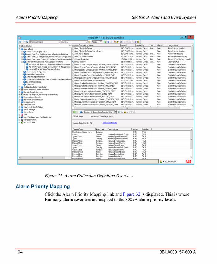
Alarm Priority Mapping Section 8 Alarm and Event System
104 3BUA000157-600 A
Alarm Priority Mapping
Click the Alarm Priority Mapping link and Figure 32 is displayed. This is where Harmony alarm severities are mapped to the 800xA alarm priority levels.
Figure 31. Alarm Collection Definition Overview

Section 8 Alarm and Event System Alarm Priority Mapping
3BUA000157-600 A 105
Refer to Table 14 for more information on priority mapping with 800xA.
Figure 32. Alarm Priority Mapping
Table 14. Priority Mapping
Harmony Alarm Priority 800xA Severity 800Xa Priority Level
1 1000 1
2 900 2
3 850 3
4 800 4
5 700 5
6 650 6
7 600 7
8 550 8
9 450 9
10 400 10
11 350 11
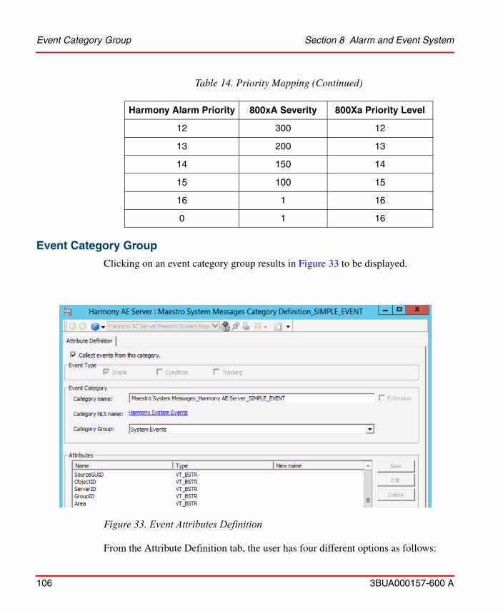
Event Category Group Section 8 Alarm and Event System
106 3BUA000157-600 A
Event Category Group
Clicking on an event category group results in Figure 33 to be displayed.
From the Attribute Definition tab, the user has four different options as follows:
12 300 12
13 200 13
14 150 14
15 100 15
16 1 16
0 1 16
Figure 33. Event Attributes Definition
Table 14. Priority Mapping (Continued)
Harmony Alarm Priority 800xA Severity 800Xa Priority Level
Section 8 Alarm and Event System Class Extended Attribute Support
3BUA000157-600 A 107
• Disable event collections for the Event Category by deselecting the Collect Events From This Category check box.
• Assign the Event Category to a different Event Category Group.
• Change the NLS name translations for the corresponding Event Attributes.
• Change the NLS translations for the Event Category’s name. Refer to Section 11, NLS Support for more information.
The user should not change the Category Name. The user should only change the Category NLS name.
Class Extended Attribute Support
800xA for Symphony Plus Harmony provides default support for an Extended Attribute named Class. Class can be used to provide a common attribute for filtering when displaying combined 800xA for Symphony Plus Harmony and 800xA AC800M Alarm and Event Displays (Class is a standard 800xA AC800M event attribute).
To enable this support, an Event Attribute Object Extension Aspect must be configured containing the Class attribute value for the Harmony Tag Objects for which the events are generated. The Event Attribute Object Extension Aspects can either be configured on the individual Tag Object instances, or they can be placed on a parent node and configured to be inherited by the child Objects in an Object hierarchy. For example if an Area hierarchy is configured in the Functional Structure, the Event Attribute Object Extension Aspects can be configured on the Area Objects and then the Class value defined would be inherited by all Objects in that Area.
To configure the Event Attribute Object Extension Aspect:
1. In the Plant Explorer, select the Object where the Class value is to be defined right-click and select New Aspect.
2. Select the List Presentation check box, select Event Attribute Object Extension, and then click Create as shown in Figure 34.

Class Extended Attribute Support Section 8 Alarm and Event System
108 3BUA000157-600 A
3. Select the newly created Event Attribute Object Extension Aspect, select the Attributes tab, then click Add.
Figure 34. Event Attribute Object Extension
Section 8 Alarm and Event System Class Extended Attribute Support
3BUA000157-600 A 109
4. In the Attribute pick list, select Class as shown in Figure 35.
Figure 35. Extended Attribute Selection
5. Specify an integer value for the Class Attribute. This is the value that the Class Event Attribute will contain for events generated for this Object and any descendants of the Object.
6. Click OK, and then click Apply as shown in Figure 36.
Figure 36. Event Attribute Object Extension Dialog Showing Attributes

System Overview Section 8 Alarm and Event System
110 3BUA000157-600 A
System OverviewEvents are generated by Servers in the system. Event concentrators collect the events from the Servers and distribute them between the different nodes and make the event stream accessible for client applications. All client applications can be configured to be sensitive to a group of events defined by an event filter and applied to the event stream in the system. Figure 37 is a functional diagram of the Harmony event system.
The design and implementation of the alarm and event system is closely related to the OPC definitions for alarms and events. For a clearer understanding, this instruction refers to the OPC terms where appropriate indicating similarities and potential differences.
Alarms and Events
An event is the notification of some occurrence that is considered significant. The event can either be related to a specific condition represented by an event point (the transition into high alarm of a tag and the respective return to normal) or non condition related events (an operator action). An event itself has no state and only
Figure 37. Harmony Event System
Section 8 Alarm and Event System Event Point
3BUA000157-600 A 111
indicates states or state changes. An event client can subscribe for notifications of specified events.
An alarm is considered an event that indicates an abnormal condition. It is a specially classified event. The classification is made through an attribute in the Event Structure and supports filtering. Harmony system alarms are process alarms and appear only in Process Alarm & Event Lists within the 800xA System.
Event Point
An event point represents a defined condition in the system. The event point generates events at the occurrence of a state change of the defined condition. It maintains its current state in terms of active or inactive, acknowledged or unacknowledged, inhibited or uninhibited, and enabled or disabled.
Usually an event point exists as part of a tag in a connectivity server. The system also provides the option to maintain transient event points for non tag related events.
Since the event point maintains the various states of a condition, only events generated by an event point (as opposed to non event point related events) can be inhibited or disabled.
The similar entity in the OPC definition is a condition. Consider the event point implementation of Harmony similar to the implementation of the abstract OPC condition model.
Event Distribution System
The event distribution system is responsible for collecting the event streams from all Servers in order to generate an overall event stream. They allow client applications to access all events in the system, even though a client application can only subscribe to a subset of the events defined by a filter. This subset is usually functionally oriented (all events of priority one or all system events) rather than Server oriented.
The event subsystem makes sure that the various Servers comprising the system are transparent to the client applications. The user can focus on functional aspects rather than knowing how tags are distributed within the system.
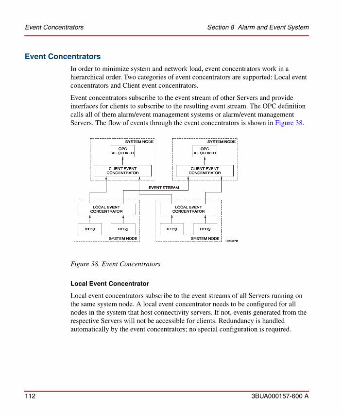
Event Concentrators Section 8 Alarm and Event System
112 3BUA000157-600 A
Event Concentrators
In order to minimize system and network load, event concentrators work in a hierarchical order. Two categories of event concentrators are supported: Local event concentrators and Client event concentrators.
Event concentrators subscribe to the event stream of other Servers and provide interfaces for clients to subscribe to the resulting event stream. The OPC definition calls all of them alarm/event management systems or alarm/event management Servers. The flow of events through the event concentrators is shown in Figure 38.
Local Event Concentrator
Local event concentrators subscribe to the event streams of all Servers running on the same system node. A local event concentrator needs to be configured for all nodes in the system that host connectivity servers. If not, events generated from the respective Servers will not be accessible for clients. Redundancy is handled automatically by the event concentrators; no special configuration is required.
Figure 38. Event Concentrators
Section 8 Alarm and Event System Event Classifications
3BUA000157-600 A 113
Client Event Concentrator
Client event concentrators subscribe to the event streams of all local event concentrators in the system that belong to the same Harmony domain as they do. A client event concentrator combines the event stream of all local event concentrators into a complete event stream of the system.
Event Classifications
Events are separated into two classifications: Alarm and Status. Typically alarm events are events that require action to resolve the reason for their generation. An example of an alarm event is a boiler temperature exceeding a limit. Status events do not require action to resolve the reason of their generation. An example of a status event is a motors state changing from on to off. The event is identified as an alarm or a status in the event point configuration.
Event Categories
Event categories can be used to condense the event state of a tag. Multiple event points in a tag can belong to the same event category. Event client applications (event pages and alarm bars) can interpret the event categories and only present the most important events to an operator instead of all events. This lowers the event noise to the operator. Example categories are Boolean, Limit, Deviation, Rate.
Event Point Definition
In Harmony an event point represents a single condition, like the high alarm or high-high alarm of a process tag. Multiple event points of one event source can be closely related. In this case the event points belong to the same event category. This gives client applications the option to detect related events and display them accordingly. The definition of event points is part of the definition of the respective tag.
Event Point Attributes
An event point in Harmony is a specialization of PSigBool. It has all the attributes defined for a Boolean signal. The various attributes can be configuration defined, accessible as properties, and updated in accordance with the state of the condition itself. Table 15 and Table 16 identify the different attributes of an event point and provide descriptions. The configuration column (Config) identifies if the attribute is

Event Point Definition Section 8 Alarm and Event System
114 3BUA000157-600 A
defined through configuration. The Property column identifies if the attribute is accessible as an property in case the event point exists as part of a tag instance.
Table 15. Event Point Identification
Attribute Description Config Property
Source Name of the source of the event point. Every event point instance is related to one source. For an event point defined as part of a tag the source is the tag name.
Yes Yes2
EventPointName Identifies the event point inside the source. The event point name is defined in the class of the tag as the signal name and is not configurable. The signal name in combination with the sender name uniquely identifies the event point: <Source>.<SignalName>.
Class1 No
NOTES: 1. The configuration is inherited from the class of the object.2. Only if the event point is defined as part of the tag.
Table 16. Event Point State
Attribute Description Config Property
SIG Represents the current state of the event point. The SIG property is updated even though the event point is not enabled.
No Yes
PRI Current priority of the event point. No Yes
AREF Associated value. Returns the current value of the property which is associated to the event point (PV for a high alarm).
Class1 Yes
UNACKEP Event point is currently unacknowledged. An event point is set to unacknowledged when it goes into active state and is configured to require acknowledge.
Yes Yes
SUP Event generation is currently suppressed by configured condition in the system.
No Yes
COM Current event comment. Returns the event comment COM0 or COM1 dependent on the active state of the event point.
No Yes
ALARM Event point is in alarm: ALARM = ACT AND ALMEN. No Yes
Section 8 Alarm and Event System Event Point Definition
3BUA000157-600 A 115
Certain attributes of an event point can be configured if the event point is defined as part of a tag. Two classes of attributes can be distinguished as Behavioral and Informational.
Behavioral Attributes
Behavioral attributes impact the behavior of the event point in terms of its state machine and actions processed upon state change. The behavioral attributes are shown in Table 17.
Informational Attributes
Informational attributes do not impact the behavior of the event point. They serve to qualify events generated by the event point to be interpreted by client applications.
UNACK Current state of the event point represents an unacknowledged alarm: UNACK = UNACKEP AND ALMEN.
No Yes
NOTE: The configuration is inherited from the class of the object.
Table 17. Behavioral Attributes
Attribute Description Config Property
ACKR Event point requires an acknowledge and will be included in the event page. Only events that have ACKR enabled will be represented in the event status page and event bar.
Yes Yes
EN Event point is enabled. If the event point is enabled it will generate events according to state changes of the event point. (An event point can be enabled by configuration action and operator action).
Yes Yes
DUAL Event point generates events on transition into active and inactive state. A non dual event point will only generate an event upon transition into active state.
Yes Yes
COMP Not implemented — —
Table 16. Event Point State (Continued)
Attribute Description Config Property
Event Point Definition Section 8 Alarm and Event System
116 3BUA000157-600 A
The informational attributes are shown in Table 18.
Event points that are not part of a tag are defined by the application generating the associated events. The configuration of such event points is up to the application itself.
Event Point State Attributes
Event points have several boolean state attributes.
The list in Table 18 represents a complete set of possible configuration attributes. The actual attributes are dependent on the implementation of the tag type, some of them are defined by default.
Table 18. Informational Attributes
Attribute Description Config Property
DESC1 Description of the event point. If no description is configured for the specific event point the description of the tag will be used instead.
Yes Yes
EPSCAT Category the event point belongs to. Defining event categories supports identification of closely related event points of one source. Event points with the same event category will be considered by a client application as closely related.
No Yes
SIG0 Defines the logic state descriptor for the zero state of the event point. Usually this attribute is defined through configuration.
Yes Yes
SIG1 Defines the logic state descriptor for the one state of the event point. Usually this attribute is defined through configuration.
Yes Yes
PRI0 Priority defined for the inactive state of the event point. Yes Yes
PRI1 Priority defined for the active state of the event point. Yes Yes
COM0 Event comment for inactive event point. Yes Yes
COM1 Event comment for active event point. Yes Yes
ALMEN Event point represents an alarm (abnormal condition). Yes Yes
NOTES:1. Only if the event point is defined as part of the tag.
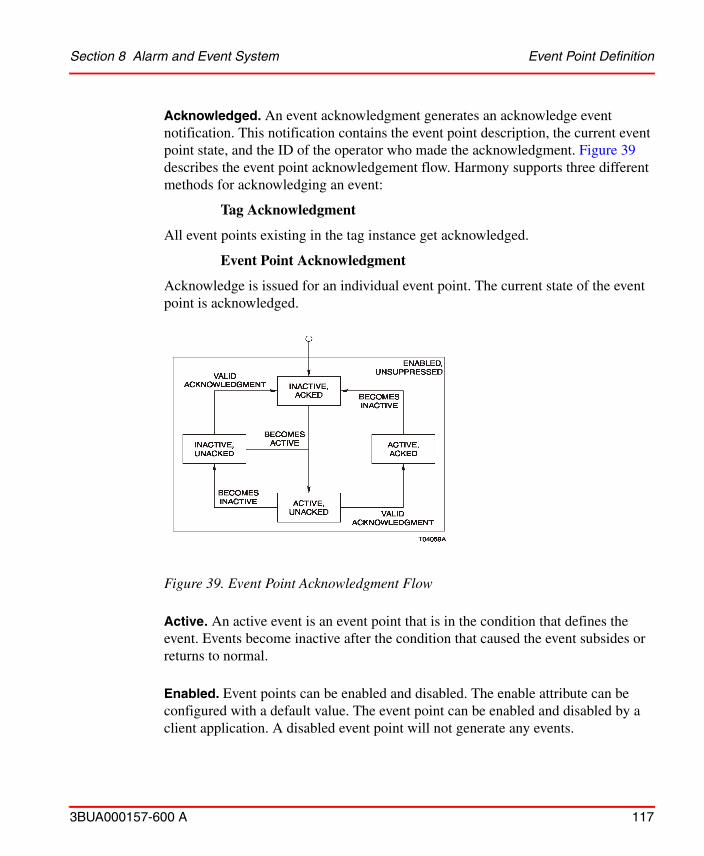
Section 8 Alarm and Event System Event Point Definition
3BUA000157-600 A 117
Acknowledged. An event acknowledgment generates an acknowledge event notification. This notification contains the event point description, the current event point state, and the ID of the operator who made the acknowledgment. Figure 39 describes the event point acknowledgement flow. Harmony supports three different methods for acknowledging an event:
Tag Acknowledgment
All event points existing in the tag instance get acknowledged.
Event Point Acknowledgment
Acknowledge is issued for an individual event point. The current state of the event point is acknowledged.
Active. An active event is an event point that is in the condition that defines the event. Events become inactive after the condition that caused the event subsides or returns to normal.
Enabled. Event points can be enabled and disabled. The enable attribute can be configured with a default value. The event point can be enabled and disabled by a client application. A disabled event point will not generate any events.
Figure 39. Event Point Acknowledgment Flow
Event Point Definition Section 8 Alarm and Event System
118 3BUA000157-600 A
Suppressed. An event point can be suppressed by defined logic. An event point, which is currently suppressed, will not generate any events. Harmony tags generically support suppressing of event points on tag level. That means all event points of the tag will be suppressed, although certain tag types can support suppressing individual event points as a reaction to other conditions.
Inhibited. An event point can be inhibited by a defined logic. An event point which is currently inhibited will generate events according to its respective event point state changes. These events will be marked as inhibited, giving a client application the option to filter the events.
Harmony tags generically support inhibiting of event points on a tag level. That means all event points of the tag will be inhibited, although certain tag types can support inhibiting individual event points as a reaction to other conditions.
Dual Event Point Behavior
Most of the event points have dual behavior. Dual events generate event notifications for active to inactive and inactive to active state transitions. Refer to Figure 39.
Non Dual Event Point Behavior
Non dual event points have slightly different behavior. Non dual event points only generate event notifications for inactive to active transitions. They automatically go inactive when they receive a valid acknowledgment.
3BUA000157-600 A 119
Section 9 Configuration Tools
Bulk Data ManagementThe 800xA Bulk Data Manager (BDM) can be used to make bulk configuration changes to the 800xA for Symphony Plus Harmony TagConfig Aspects.
Pre-defined sample BDM templates are provided for each 800xA for Symphony Plus Harmony Tag type that can be used to make bulk Tag configuration changes to Tags of the same type. Users can also make ad-hoc changes to the Harmony TagConfig Aspects and create their own BDM templates.
ABB does not recommend making bulk configuration changes online. When bulk changes are made, it is recommended that online change notifications are disabled. Each system may exhibit different update performance. ABB recommends disabling online changes if more than 100 Tags are being added, updated or removed.
Ad-hoc Bulk Changes Section 9 Configuration Tools
120 3BUA000157-600 A
Ad-hoc Bulk Changes
1. Select Bulk Data Manager from the Advanced Object context menu in the Engineering Workplace. This will launch Microsoft Excel and activate the Bulk Data Manager Excel Add-In as shown in Figure 40 and Figure 41.
Figure 40. Selecting Bulk Data Manager from the Workplace
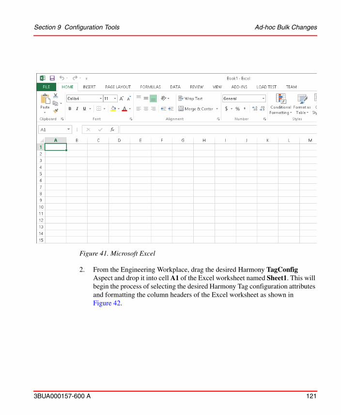
Section 9 Configuration Tools Ad-hoc Bulk Changes
3BUA000157-600 A 121
2. From the Engineering Workplace, drag the desired Harmony TagConfig
Aspect and drop it into cell A1 of the Excel worksheet named Sheet1. This will begin the process of selecting the desired Harmony Tag configuration attributes and formatting the column headers of the Excel worksheet as shown in Figure 42.
Figure 41. Microsoft Excel
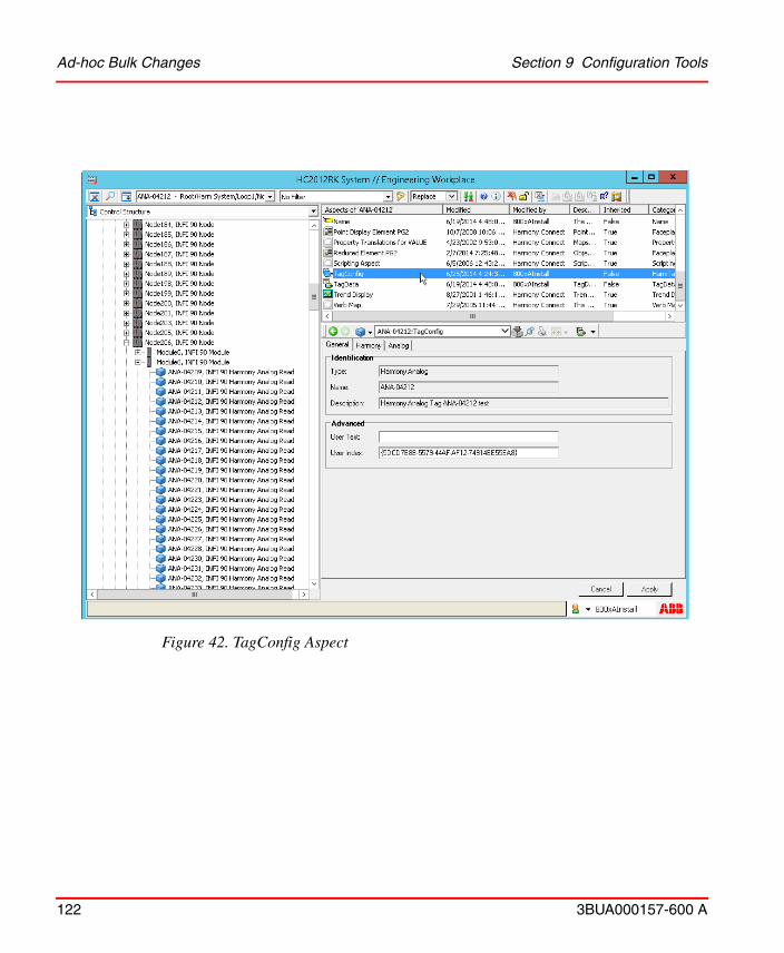
Ad-hoc Bulk Changes Section 9 Configuration Tools
122 3BUA000157-600 A
Figure 42. TagConfig Aspect
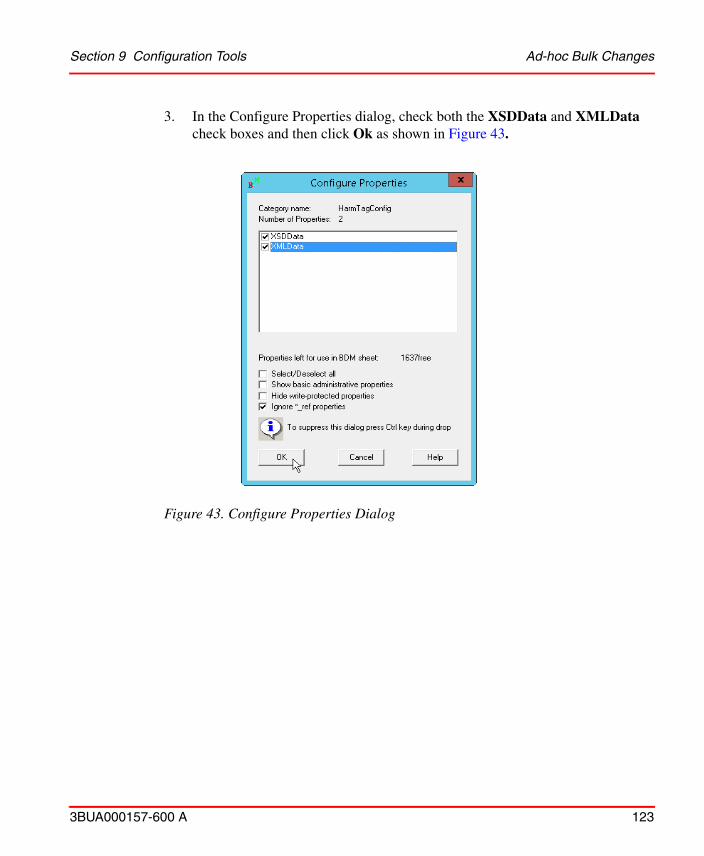
Section 9 Configuration Tools Ad-hoc Bulk Changes
3BUA000157-600 A 123
3. In the Configure Properties dialog, check both the XSDData and XMLData check boxes and then click Ok as shown in Figure 43.
Figure 43. Configure Properties Dialog
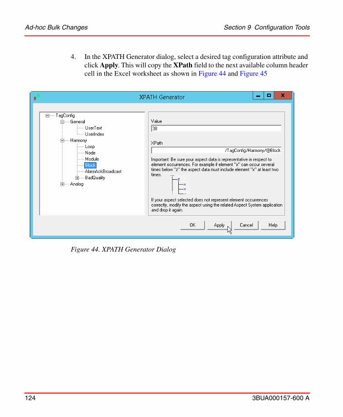
Ad-hoc Bulk Changes Section 9 Configuration Tools
124 3BUA000157-600 A
4. In the XPATH Generator dialog, select a desired tag configuration attribute and click Apply. This will copy the XPath field to the next available column header cell in the Excel worksheet as shown in Figure 44 and Figure 45
Figure 44. XPATH Generator Dialog

Section 9 Configuration Tools Ad-hoc Bulk Changes
3BUA000157-600 A 125
5. Repeat Step 4 until all the desired Tag configuration attributes have been
selected. After selecting the last attribute, click OK.
Figure 45. XPATH Generator Dialog - Showing the Copied Path
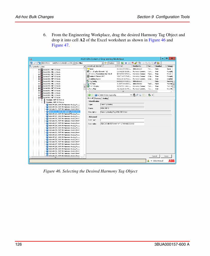
Ad-hoc Bulk Changes Section 9 Configuration Tools
126 3BUA000157-600 A
6. From the Engineering Workplace, drag the desired Harmony Tag Object and drop it into cell A2 of the Excel worksheet as shown in Figure 46 and Figure 47.
Figure 46. Selecting the Desired Harmony Tag Object
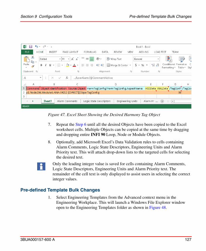
Section 9 Configuration Tools Pre-defined Template Bulk Changes
3BUA000157-600 A 127
7. Repeat the Step 6 until all the desired Objects have been copied to the Excel worksheet cells. Multiple Objects can be copied at the same time by dragging and dropping entire INFI 90 Loop, Node or Module Objects.
8. Optionally, add Microsoft Excel’s Data Validation rules to cells containing Alarm Comments, Logic State Descriptors, Engineering Units and Alarm Priority text. This will attach drop-down lists to the targeted cells for selecting the desired text.
Only the leading integer value is saved for cells containing Alarm Comments, Logic State Descriptors, Engineering Units and Alarm Priority text. The remainder of the cell text is only displayed to assist users in selecting the correct integer values.
Pre-defined Template Bulk Changes
1. Select Engineering Templates from the Advanced context menu in the Engineering Workplace. This will launch a Windows File Explorer window open to the Engineering Templates folder as shown in Figure 48.
Figure 47. Excel Sheet Showing the Desired Harmony Tag Object

Pre-defined Template Bulk Changes Section 9 Configuration Tools
128 3BUA000157-600 A
Figure 48. Windows File Explorer Window
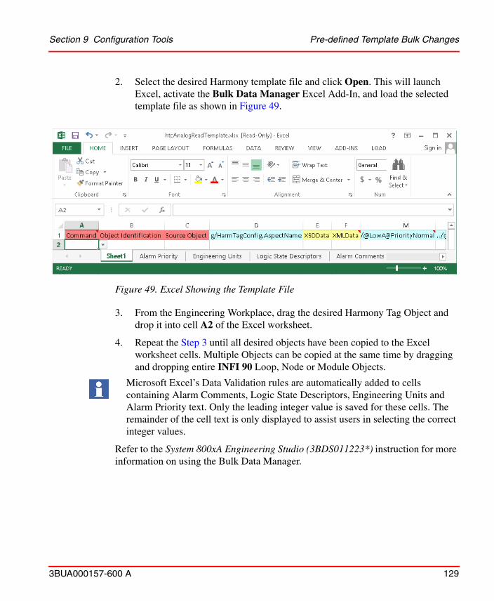
Section 9 Configuration Tools Pre-defined Template Bulk Changes
3BUA000157-600 A 129
2. Select the desired Harmony template file and click Open. This will launch Excel, activate the Bulk Data Manager Excel Add-In, and load the selected template file as shown in Figure 49.
Figure 49. Excel Showing the Template File
3. From the Engineering Workplace, drag the desired Harmony Tag Object and drop it into cell A2 of the Excel worksheet.
4. Repeat the Step 3 until all desired objects have been copied to the Excel worksheet cells. Multiple Objects can be copied at the same time by dragging and dropping entire INFI 90 Loop, Node or Module Objects.
Microsoft Excel’s Data Validation rules are automatically added to cells containing Alarm Comments, Logic State Descriptors, Engineering Units and Alarm Priority text. Only the leading integer value is saved for these cells. The remainder of the cell text is only displayed to assist users in selecting the correct integer values.
Refer to the System 800xA Engineering Studio (3BDS011223*) instruction for more information on using the Bulk Data Manager.
Environment Support Section 9 Configuration Tools
130 3BUA000157-600 A
Environment Support800xA for Symphony Plus Harmony Aspects can be configured in an Engineering Environment and deployed to a Production Environment.
Uploading Harmony Tag Configuration to Engineering Environment
1. Create a new System with the Configuration Wizard and then select the Environment Setup from the System Administration menu as shown in
ABB does not recommend making bulk configuration changes online. When bulk changes are made, it is recommended that online change notifications are disabled. Each system may exhibit different update performance. ABB recommends disabling online changes if more than 100 Tags are being added, updated or removed.
A Refresh Engineering Environment operation should be performed prior to making and deploying changes from the Engineering Environment. This is to prevent the overwriting of changes that have been made in the Production Environment.
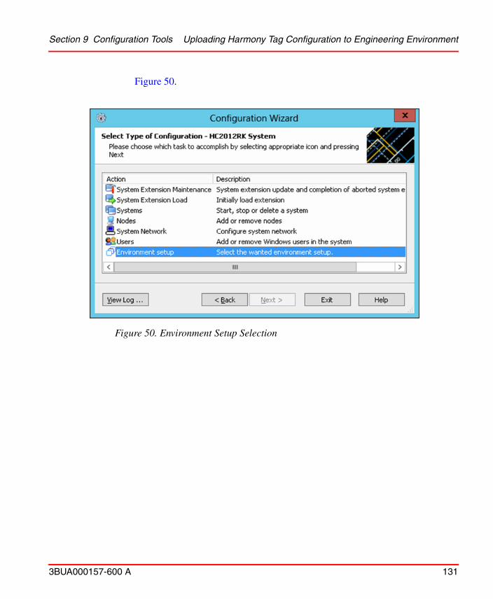
Section 9 Configuration Tools Uploading Harmony Tag Configuration to Engineering Environment
3BUA000157-600 A 131
Figure 50.
Figure 50. Environment Setup Selection

Uploading Harmony Tag Configuration to Engineering Environment Section 9 Configuration Tools
132 3BUA000157-600 A
2. Select Configure-Deploy support option and then click Next as shown in Figure 51.
Figure 51. Configure-Deploy Support
3. Load Harmony System Extension using the Configuration Wizard.
4. Open Production Workplace and then create a Harmony OPC Server Network Object in Control Structure as shown in Figure 52.
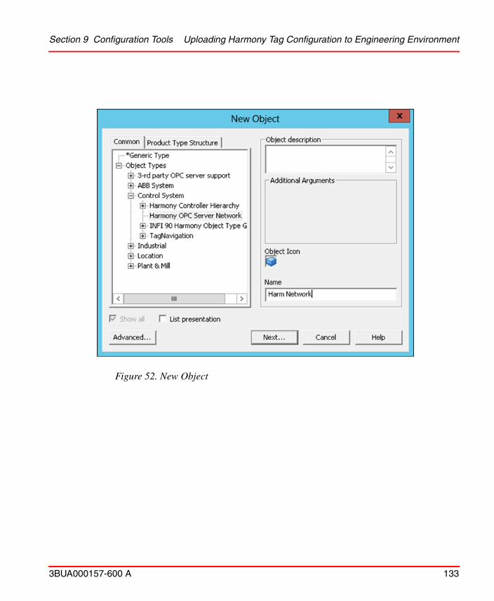
Section 9 Configuration Tools Uploading Harmony Tag Configuration to Engineering Environment
3BUA000157-600 A 133
Figure 52. New Object
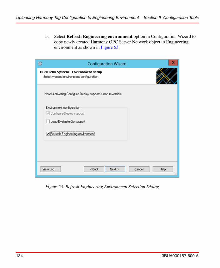
Uploading Harmony Tag Configuration to Engineering Environment Section 9 Configuration Tools
134 3BUA000157-600 A
5. Select Refresh Engineering environment option in Configuration Wizard to copy newly created Harmony OPC Server Network object to Engineering environment as shown in Figure 53.
Figure 53. Refresh Engineering Environment Selection Dialog
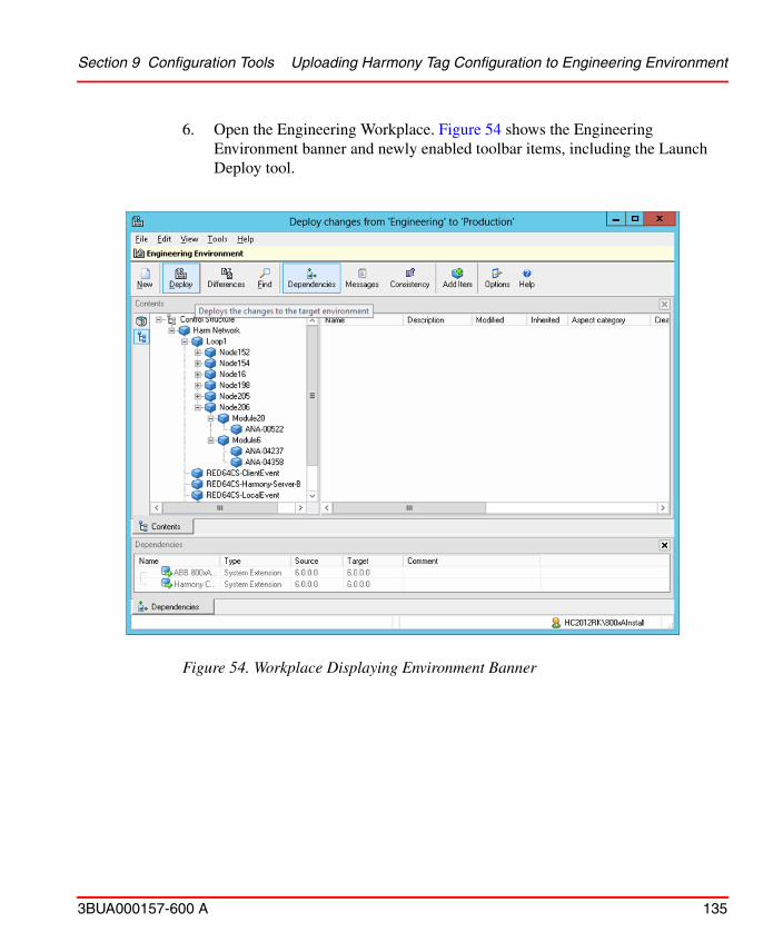
Section 9 Configuration Tools Uploading Harmony Tag Configuration to Engineering Environment
3BUA000157-600 A 135
6. Open the Engineering Workplace. Figure 54 shows the Engineering Environment banner and newly enabled toolbar items, including the Launch Deploy tool.
Figure 54. Workplace Displaying Environment Banner
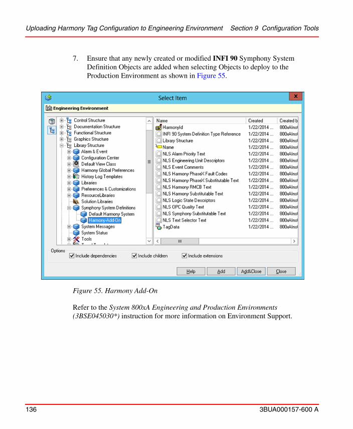
Uploading Harmony Tag Configuration to Engineering Environment Section 9 Configuration Tools
136 3BUA000157-600 A
7. Ensure that any newly created or modified INFI 90 Symphony System Definition Objects are added when selecting Objects to deploy to the Production Environment as shown in Figure 55.
Figure 55. Harmony Add-On
Refer to the System 800xA Engineering and Production Environments (3BSE045030*) instruction for more information on Environment Support.
3BUA000157-600 A 137
Section 10 Additional Harmony Settings
IntroductionAdditional 800xA for Symphony Plus Harmony settings are described in this section.
Security Settings for Operating ParametersThe user security for the Operating Parameters must be implemented as follows:
1. Refer to and perform all steps in the System Domain in the System 800xA Administration and Security (3BSE037410*) instruction.
2. From the Administrator Structure, select Administrative Objects.
3. Select Domains > System Domains > Security Definition aspect.
4. Select the type of permission to edit from the Permission field and select the Edit button.
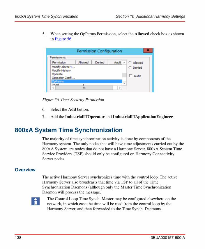
800xA System Time Synchronization Section 10 Additional Harmony Settings
138 3BUA000157-600 A
5. When setting the OpParms Permission, select the Allowed check box as shown in Figure 56.
Figure 56. User Security Permission
6. Select the Add button.
7. Add the IndustrialITOperator and IndustrialITApplicationEngineer.
800xA System Time SynchronizationThe majority of time synchronization activity is done by components of the Harmony system. The only nodes that will have time adjustments carried out by the 800xA System are nodes that do not have a Harmony Server. 800xA System Time Service Providers (TSP) should only be configured on Harmony Connectivity Server nodes.
Overview
The active Harmony Server synchronizes time with the control loop. The active Harmony Server also broadcasts that time via TSP to all of the Time Synchronization Daemons (although only the Master Time Synchronization Daemon will process the message.
The Control Loop Time Synch. Master may be configured elsewhere on the network, in which case the time will be read from the control loop by the Harmony Server, and then forwarded to the Time Synch. Daemons.

Section 10 Additional Harmony Settings Overview
3BUA000157-600 A 139
The Master Time Synchronization Daemon will post the time to all other Time Synchronization Daemons on the network. If necessary, slewing of time will begin at a rate of one second adjustment per minute on nodes that need to have their time adjusted.
The 800xA System Time Server will periodically broadcast the time on the active (in Service state) Time Server to all Client Time Handlers. If a Client Time Handler detects a time difference between the Time Server's time and the local time that is greater than the configured deviation limit, it will attempt to adjust the time on the local node (by doing a step change to the system time).
When a Connectivity Server node is added to the system, a Time Server service provider is automatically added to Services > Time, Service > Basic, Service Group > Time Basic > <computername> > Service Provider. The service provider can be configured via the Service Provider Definition aspect. Refer to Figure 57.
Any service providers added for nodes that do not have Harmony Server installed, must be removed or disabled (otherwise the active Time Server could end up broadcasting a time that is very different from the Time Synchronization Daemon
Figure 57. Service Provider Definition

Time Synchronization Section 10 Additional Harmony Settings
140 3BUA000157-600 A
time). All 800xA System nodes, whether they are client or Server nodes, have a TimeServerHandler aspect in the Node Administration Structure under Node Administration > All Nodes, Node Group > <computer name>, Node. Refer to Figure 58.
The Allowed To Set Time option should be unchecked for all nodes, to prevent users from changing the system clock.
Time SynchronizationThe Harmony Server tags should be configured to allow Time Synchronization in the TagConfig aspect. If a node other than a Harmony Connectivity Server is to act as Time Synchronization Master on the control loop, then the accuracy setting should be set as Low Accuracy Battery on both Servers. If the Harmony Connectivity Server pairs are to act as Time Synchronization master on the control loop, then the accuracy setting should be set at some level higher than Low Accuracy Battery for both nodes. The primary setting must be slightly higher than the redundant. In addition, if the node is to act as the default TSP master, the TSP network priority should be set a number higher than any of the other nodes on the network. If a node other than Harmony Connectivity Servers is to act as the default TSP Time Sync Master, then the Network Priority should be set at 1. The range is 1 to 10, where 10 is the highest priority. All Harmony Connectivity Servers must use the same network segment for Time Sync communication.
Figure 58. Time Sync Run Option
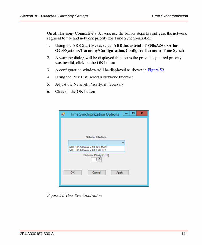
Section 10 Additional Harmony Settings Time Synchronization
3BUA000157-600 A 141
On all Harmony Connectivity Servers, use the follow steps to configure the network segment to use and network priority for Time Synchronization:
1. Using the ABB Start Menu, select ABB Industrial IT 800xA/800xA for OCS/Systems/Harmony/Configuration/Configure Harmony Time Synch
2. A warning dialog will be displayed that states the previously stored priority was invalid, click on the OK button
3. A configuration window will be displayed as shown in Figure 59.
4. Using the Pick List, select a Network Interface
5. Adjust the Network Priority, if necessary
6. Click on the OK button
Figure 59. Time Synchronization
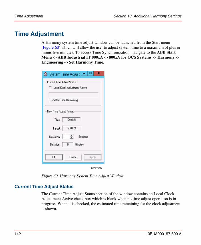
Time Adjustment Section 10 Additional Harmony Settings
142 3BUA000157-600 A
Time AdjustmentA Harmony system time adjust window can be launched from the Start menu (Figure 60) which will allow the user to adjust system time to a maximum of plus or minus five minutes. To access Time Synchronization, navigate to the ABB Start Menu -> ABB Industrial IT 800xA -> 800xA for OCS Systems -> Harmony -> Engineering -> Set Harmony Time.
Current Time Adjust Status
The Current Time Adjust Status section of the window contains an Local Clock Adjustment Active check box which is blank when no time adjust operation is in progress. When it is checked, the estimated time remaining for the clock adjustment is shown.
TC02713B
Figure 60. Harmony System Time Adjust Window
Section 10 Additional Harmony Settings New Time Adjust Target
3BUA000157-600 A 143
New Time Adjust Target
The New Time Adjust Target section provides information the user needs to issue a new time adjustment to the system.
The Time field provides the user with the current system time. The Target field provides the user with the target time of the new adjustment operation. These two fields will be updated every half second. The Deviation field will be used to enter a time adjustment, in seconds, into the system. Changing the deviation will result in the target and duration fields being updated to indicate the affect of the proposed change prior to committing it. This field will be limited to plus or minus 300 seconds. The Duration field will provide the approximate length of time, in minutes, needed to complete the new time adjustment operation. It will be based on the current deviation of the fixed time adjustment rate of two seconds of adjustment per minute. This field will be updated every time the user changes the deviation field.
Three buttons are provided at the bottom of the window. Use Apply to accept the deviation request in the new deviation field. The application will issue a request to the Master Timesync Daemon to adjust the time to the new settings. The application will then issue a notification to each Harmony Server to indicate the start of a time adjustment. OK will perform the functions defined for Apply, and will then close the window. These buttons will be dimmed and inactive if the current user does not have database configuration access.
The Estimated Time Remaining field is the time it will take for the local clock to adjust to the requested time change. Each time an adjustment is being done, the Adjust Local Clock Adjustment check box will be selected.
AuthenticationTo configure a system for reauthentication or double authentication:
1. Go to the Control Structure in the Workplace.
2. From the Harmony OPC Server Network, select a tag to configure.
3. Select the Control Connection aspect.
4. Select the Property Info tab as shown in Figure 61.
This time adjustment can be initiated from any Harmony Connectivity Server node on the network.
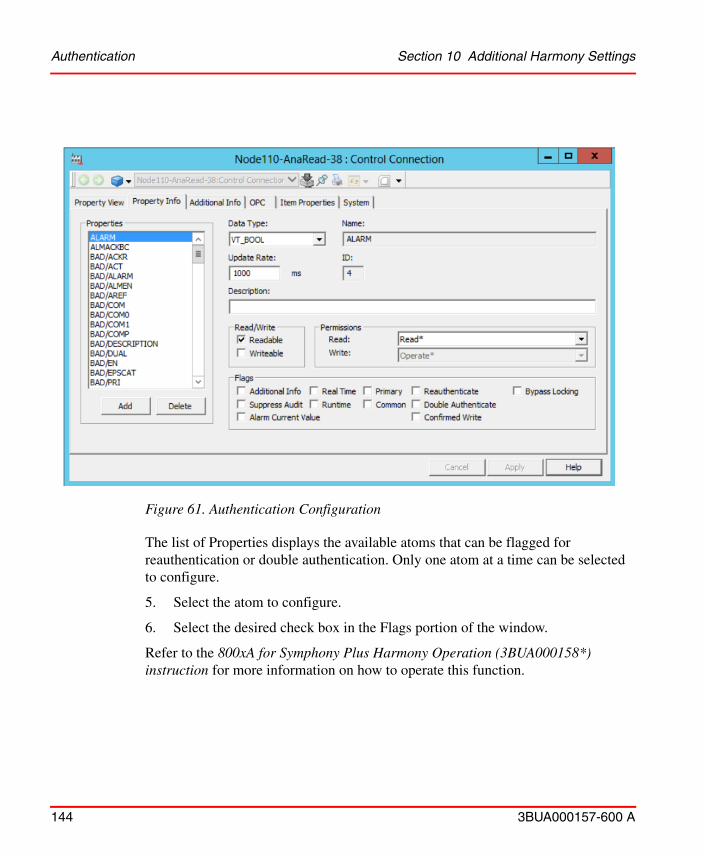
Authentication Section 10 Additional Harmony Settings
144 3BUA000157-600 A
The list of Properties displays the available atoms that can be flagged for reauthentication or double authentication. Only one atom at a time can be selected to configure.
5. Select the atom to configure.
6. Select the desired check box in the Flags portion of the window.
Refer to the 800xA for Symphony Plus Harmony Operation (3BUA000158*) instruction for more information on how to operate this function.
Figure 61. Authentication Configuration
Section 10 Additional Harmony Settings Hot Keys
3BUA000157-600 A 145
Hot KeysHot Keys are accessed and then configured via the Harmony Operator Workplace as follows:
Workplace Structure > Web System Workplace > Harmony Operator Workplace > Hot Keys
The Hot Keys Map file viewer aspect for this workplace lists the new Hot Keys of the expanded Harmony Hot Keys aspect, in addition to the existing keys.

Hot Keys Section 10 Additional Harmony Settings
146 3BUA000157-600 A
3BUA000157-600 A 147
Section 11 NLS Support
Introduction800xA for Symphony Plus Harmony supports any locale. The software must be installed under the English locale and then be localized to execute under any other locale.
Add New Locale to Desktop
Execute the following to add new locale to desktop:
1. Select Control Panel > Region and Language Options.
2. From the Location tab, choose the new locale to be used in the drop-down list box.
3. Click OK.
4. The new locale will be available for selection through the task bar. Select the new locale and a check mark will appear next to the selected locale.
Add New Locale for Internet Explorer
Open an Internet Explorer window and execute the following:
1. Select Tools > Internet Options.
2. Click Languages.
3. Click Set Language Preference.
4. Select Add a language.
5. Select the new locale to be added.
Dynamically switching between locales is not supported. Only one locale can be used at a time.
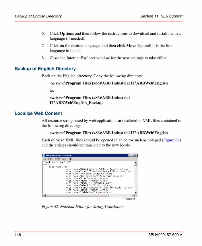
Backup of English Directory Section 11 NLS Support
148 3BUA000157-600 A
6. Click Options and then follow the instructions to download and install the new language (if needed).
7. Click on the desired language, and then click Move Up until it is the first language in the list.
8. Close the Internet Explorer window for the new settings to take effect.
Backup of English Directory
Back up the English directory. Copy the following directory:
<drive>:\Program Files (x86)\ABB Industrial IT\ABBWeb\English
to:
<drive>:\Program Files (x86)\ABB Industrial IT\ABBWeb\English_Backup
Localize Web Content
All resource strings used by web applications are isolated in XML files contained in the following directory:
<drive>:\Program Files (x86)\ABB Industrial IT\ABBWeb\English
Each of these XML files should be opened in an editor such as notepad (Figure 62) and the strings should be translated to the new locale.
TC06074A
Figure 62. Notepad Editor for String Translation
Section 11 NLS Support Localize Windows Applications
3BUA000157-600 A 149
Translate only the strings within the <res> </res> or <resource> <resource> tags. Do not modify any text between the < > brackets. Once all the strings are changed, open the XML file in Internet Explorer. The XML will be successfully loaded. If by accident some of the <> tags have been modified, the Internet Explorer will fail to load the file displaying an appropriate error message. IIS needs to be restarted before the changes take effect for some applications.
Localize Windows Applications
Windows applications use resource DLLs to isolate language specific strings. A third party tool such as VisualStudio or VisualLocalize must be used to translate the resources into different languages.
The following table (Table 19) is a list of windows applications and their corresponding resource DLLs that need to be translated. Make copies of the original versions of these files to a backup directory.
Table 19. Applications and DLLs
Application Path Resource DLL Related Feature
\ABB Industrial IT\OperateIT\Base\EbTimeSet.dll EbTimeSetRes.dll Time Synchronization Utility.
\ABB Industrial IT\OperateIT\Harmony Add-On\Harm.dll
HarmRes.dll Harmony Connectivity Server Web Pages.
\ABB Industrial IT\OperateIT\Base\EvCon.dll EvConRes.dll Event Concentrator.
\ABB Industrial IT\OperateIT\Base\Server.dll 1 ServerRes.dll Harmony Connectivity Server.
\ABB Industrial IT\OperateIT\Base\SymRes.dll 1 SymRes.dll Harmony Connectivity Server Web Pages.
NOTE: 1. Can also be found in the \ABB Industrial IT\OperateIT\Harmony Add-On\ folder.
Localize Faceplates Section 11 NLS Support
150 3BUA000157-600 A
The following table (Table 20) lists resource files that are related to (unsupported) diagnostic applications that can be translated.
Localize Faceplates
Resource strings used in faceplates are isolated using the Harmony NLS Resource Manager.
To access this function, select:
Harmony NLS Resource Manager, select: Object Type Structure > Object Types > Control System, Object Type Group > Harmony OPC Server Network, Object Type.
Table 20. Applications and DLLs Next
Application Path Resource DLLRelated Feature
\ABB Industrial IT\OperateIT\Harmony Add-On\EbModuleStatusRes.dll
EbModuleStatusRes.dll Modules Status Application.

Figure 63. Harmony NLS Object Type Structure Dialog
Section 11 NLS Support Localize Faceplates
3BUA000157-600 A 151
General Tab
This tab allows for translation of individual resource strings. Use the Add button to add a new locale and localize the string in the Translated Text area.
XML Data Tab
This tab is used to export and import resource strings to and from an XML file.
Software Upgrades Section 11 NLS Support
152 3BUA000157-600 A
Software Upgrades
When performing software upgrades, some of the files which were localized may be overridden. Back up all files in the following directory:
<Drive>:\Program Files (x86)\ABB Industrial IT\ABBWeb\English
3BUA000157-600 A 153
Section 12 Advanced Harmony Control System Monitoring
OverviewAdvanced Harmony control system monitoring is an aspect on the Harmony ModStat Read Object type.
Execute the following steps to configure Advanced Harmony control system:
1. Add the Harmony Control Equipment Asset Monitor aspect to the Harmony ModStat Read Object type.
2. Open the Object Type Definition aspect on the Harmony ModStat Read Object type and select Copy to all instances in the Aspect Control tab for the newly added Asset Monitor aspect.
Refer to the System 800xA Asset Optimization Configuration (3BUA000118*) instruction for more detailed information on configuring asset monitors.
Module Status tag created in the system will have the Harmony Control Equipment Asset Monitor aspect. The aspects configuration is defaulted to the correct configuration for normal operation and is Enabled on the Default AO Server. This configuration does not need to be adjusted unless to disable the asset monitor, inhibit one or more of its conditions, or enable it on a different AO Server.
When new instances of the Harmony Mod Stat Read object with the Harmony Control Equipment Asset Monitor aspect are created, load the configuration for the Asset Monitors to make them operational.
Execute one of the two following procedures:
Refer to the System 800xA Asset Optimization Configuration (3BUA000118*) instruction for more detailed information on disabling a single instance of the Asset Monitor or enabling it for a different AO Server.
Overview Section 12 Advanced Harmony Control System Monitoring
154 3BUA000157-600 A
• Incrementally load the configuration for the Asset Monitor on each instance of the Module Status tag in the Control Structure.
– Open the Harmony Control Equipment Asset Monitor aspects Config View.
– On the Asset Monitor tab, click the Load Configuration to AO Server button.
– Click Continue on the dialog box that appears. The Status indicator changes to Loaded, current.
• Load the configuration for multiple or all asset monitors immediately on the Asset Optimization Server aspect in the Control Structure. This aspect is found as follows:
Root > Asset Optimization > AO Server 1 Object
– Select Asset Optimization Server in the Aspect List Area.
– Select the Asset Monitors tab in the Preview Area. Ensure that the Asset Monitor aspects to be loaded are assigned to the target Asset Optimization Server and are enabled.
– Click Load All AMs to load the configured Asset Monitor aspects to the Asset Optimization Server.
The Harmony Control Equipment Asset Monitor has several conditions that are summaries of different functional areas of the Harmony modules. Each condition can be independently inhibited if required.
Execute the following to inhibit the conditions for an instance of the Asset Monitor that is on a Module Status tag in the Control Structure:
1. Open the Config View for the Harmony Control Equipment Asset Monitor on one of the Module Status tags.
2. Activate the Asset Parameters tab.
3. To disable the monitoring of the status byte information that is reflected by one of the conditions, uncheck the Inherit Configuration box and change the value of one or more of the Asset Parameters to On.
4. Click Apply to save changes.
Reload the asset monitor configuration to the AO Server for changes to take effect.
3BUA000157-600 A 155
Section 13 Harmony Batch Support
IntroductionBatch processing with 800xA for Symphony Plus Harmony uses the PHASEX function block. Although PHASEX is similar to the traditional batch sequence (BSEQ) function block used to run process control sequences, PHASEX incorporates some important features needed to achieve flexible batch process control. PHASEX differs from the BSEQ function block in its phase by phase interface with the batch management system and other enhancements.
Refer to the System 800xA Batch Management Configuration (3BUA000146*) instruction for the procedures to configure 800xA for Symphony Plus Harmony for use with Batch Management.
Introduction Section 13 Harmony Batch Support
156 3BUA000157-600 A
3BUA000157-600 A 157
Appendix A Signal Structure
IntroductionThis appendix contains tables that list the properties for the Harmony tag objects and the Harmony Server object.
Harmony Property TypesThe following Harmony property types are:
• Bool - Boolean. • St - String.• Int - Integer value.• Unit - Unassigned integer value.• Date - Date format.• Real - Real value.
Common PropertiesThe common Harmony properties appear in all Harmony tag types. Table 21 lists the common properties and includes the data type and a description for each.
Table 21. Common Harmony Properties
Name Type Description
ALARM Bool Overall alarm status.
BAD/ACKR Bool Acknowledge required.
BAD/ACT Bool Active.
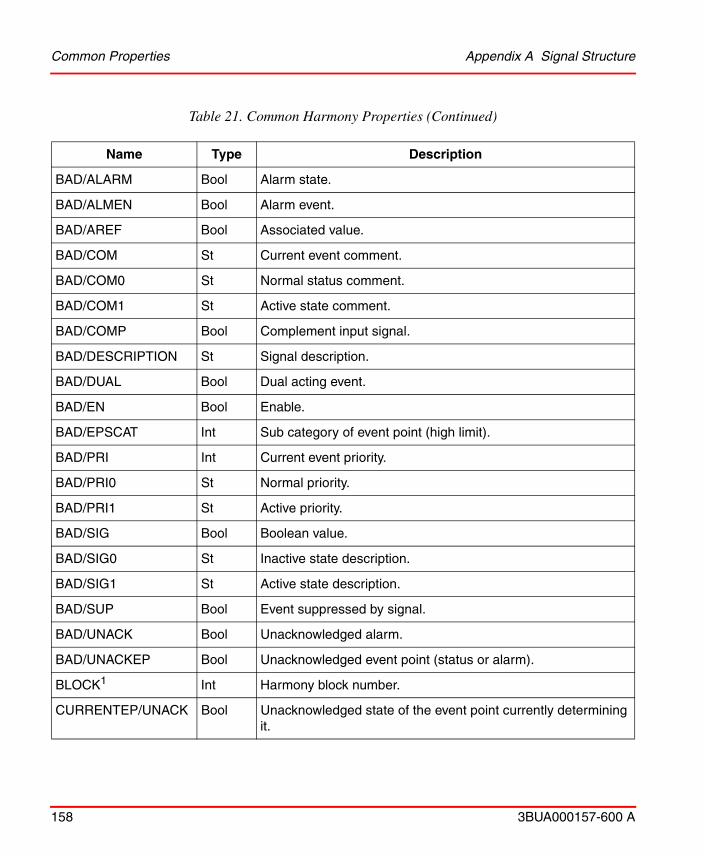
Common Properties Appendix A Signal Structure
158 3BUA000157-600 A
BAD/ALARM Bool Alarm state.
BAD/ALMEN Bool Alarm event.
BAD/AREF Bool Associated value.
BAD/COM St Current event comment.
BAD/COM0 St Normal status comment.
BAD/COM1 St Active state comment.
BAD/COMP Bool Complement input signal.
BAD/DESCRIPTION St Signal description.
BAD/DUAL Bool Dual acting event.
BAD/EN Bool Enable.
BAD/EPSCAT Int Sub category of event point (high limit).
BAD/PRI Int Current event priority.
BAD/PRI0 St Normal priority.
BAD/PRI1 St Active priority.
BAD/SIG Bool Boolean value.
BAD/SIG0 St Inactive state description.
BAD/SIG1 St Active state description.
BAD/SUP Bool Event suppressed by signal.
BAD/UNACK Bool Unacknowledged alarm.
BAD/UNACKEP Bool Unacknowledged event point (status or alarm).
BLOCK1 Int Harmony block number.
CURRENTEP/UNACK Bool Unacknowledged state of the event point currently determining it.
Table 21. Common Harmony Properties (Continued)
Name Type Description
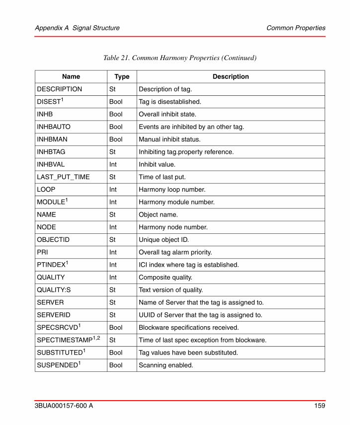
Appendix A Signal Structure Common Properties
3BUA000157-600 A 159
DESCRIPTION St Description of tag.
DISEST1 Bool Tag is disestablished.
INHB Bool Overall inhibit state.
INHBAUTO Bool Events are inhibited by an other tag.
INHBMAN Bool Manual inhibit status.
INHBTAG St Inhibiting tag.property reference.
INHBVAL Int Inhibit value.
LAST_PUT_TIME St Time of last put.
LOOP Int Harmony loop number.
MODULE1 Int Harmony module number.
NAME St Object name.
NODE Int Harmony node number.
OBJECTID St Unique object ID.
PRI Int Overall tag alarm priority.
PTINDEX1 Int ICI index where tag is established.
QUALITY Int Composite quality.
QUALITY:S St Text version of quality.
SERVER St Name of Server that the tag is assigned to.
SERVERID St UUID of Server that the tag is assigned to.
SPECSRCVD1 Bool Blockware specifications received.
SPECTIMESTAMP1,2 St Time of last spec exception from blockware.
SUBSTITUTED1 Bool Tag values have been substituted.
SUSPENDED1 Bool Scanning enabled.
Table 21. Common Harmony Properties (Continued)
Name Type Description

Common Analog Properties Appendix A Signal Structure
160 3BUA000157-600 A
Common Analog PropertiesTable 22 through Table 27 list all the properties specific to each of the Analog tag types. Table 22 lists the Common Analog properties. These are also the properties for the Analog tag. The Analog tag has all the properties in Table 22 and Table 22. The RMSC tag is an exception to the Analog tags. The properties listed in Table 27 are the only Analog properties that are available for the tag (the RMSC tag structure is the common Harmony properties and the RMSC properties).
TEMPLATEID St Object ID of the template used to create this tag.
TYPE St Object type name.
TYPEID St Object type ID.
UNACK Bool Unacknowledged alarm.
USERDATA Unit Writable user data field.
USERTEXT St User specific text (optional).
XR_COUNT1 Int Number of Real Time Data events.
NOTES: 1. Not in the HarmServer tag.2. Not in the HarmAngExport and HarmDigExport
Table 22. Common Analog Properties (HarmAnalog)
Name Type Description
ALMACKBC Bool Broadcast alarm acknowledge events.
CALIBSTS Bool Calibration status.
HIGH/ACKR Bool Acknowledge required.
HIGH/ACT Bool Active.
HIGH/ALARM Bool Alarm state.
Table 21. Common Harmony Properties (Continued)
Name Type Description
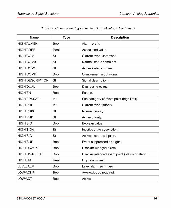
Appendix A Signal Structure Common Analog Properties
3BUA000157-600 A 161
HIGH/ALMEN Bool Alarm event.
HIGH/AREF Real Associated value.
HIGH/COM St Current event comment.
HIGH/COM0 St Normal status comment.
HIGH/COM1 St Active state comment.
HIGH/COMP Bool Complement input signal.
HIGH/DESCRIPTION St Signal description.
HIGH/DUAL Bool Dual acting event.
HIGH/EN Bool Enable.
HIGH/EPSCAT Int Sub category of event point (high limit).
HIGH/PRI Int Current event priority.
HIGH/PRI0 St Normal priority.
HIGH/PRI1 St Active priority.
HIGH/SIG Bool Boolean value.
HIGH/SIG0 St Inactive state description.
HIGH/SIG1 St Active state description.
HIGH/SUP Bool Event suppressed by signal.
HIGH/UNACK Bool Unacknowledged alarm.
HIGH/UNACKEP Bool Unacknowledged event point (status or alarm).
HIGHLIM Real High alarm limit.
LEVELALM Bool Level alarm summary.
LOW/ACKR Bool Acknowledge required.
LOW/ACT Bool Active.
Table 22. Common Analog Properties (HarmAnalog) (Continued)
Name Type Description
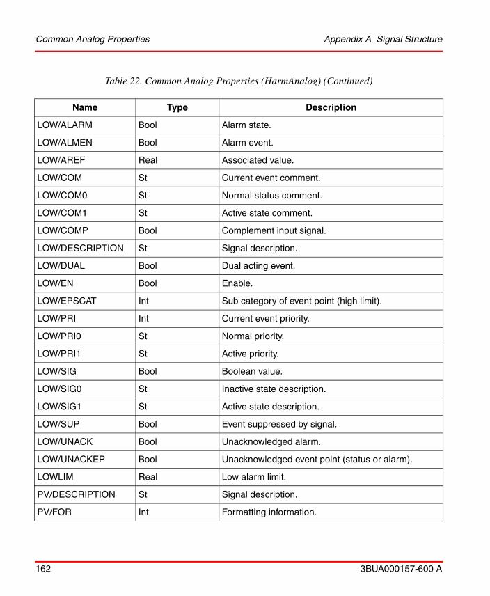
Common Analog Properties Appendix A Signal Structure
162 3BUA000157-600 A
LOW/ALARM Bool Alarm state.
LOW/ALMEN Bool Alarm event.
LOW/AREF Real Associated value.
LOW/COM St Current event comment.
LOW/COM0 St Normal status comment.
LOW/COM1 St Active state comment.
LOW/COMP Bool Complement input signal.
LOW/DESCRIPTION St Signal description.
LOW/DUAL Bool Dual acting event.
LOW/EN Bool Enable.
LOW/EPSCAT Int Sub category of event point (high limit).
LOW/PRI Int Current event priority.
LOW/PRI0 St Normal priority.
LOW/PRI1 St Active priority.
LOW/SIG Bool Boolean value.
LOW/SIG0 St Inactive state description.
LOW/SIG1 St Active state description.
LOW/SUP Bool Event suppressed by signal.
LOW/UNACK Bool Unacknowledged alarm.
LOW/UNACKEP Bool Unacknowledged event point (status or alarm).
LOWLIM Real Low alarm limit.
PV/DESCRIPTION St Signal description.
PV/FOR Int Formatting information.
Table 22. Common Analog Properties (HarmAnalog) (Continued)
Name Type Description
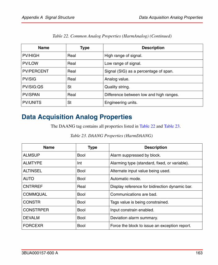
Appendix A Signal Structure Data Acquisition Analog Properties
3BUA000157-600 A 163
Data Acquisition Analog Properties
The DAANG tag contains all properties listed in Table 22 and Table 23.
PV/HIGH Real High range of signal.
PV/LOW Real Low range of signal.
PV/PERCENT Real Signal (SIG) as a percentage of span.
PV/SIG Real Analog value.
PV/SIG:QS St Quality string.
PV/SPAN Real Difference between low and high ranges.
PV/UNITS St Engineering units.
Table 23. DAANG Properties (HarmDAANG)
Name Type Description
ALMSUP Bool Alarm suppressed by block.
ALMTYPE Int Alarming type (standard, fixed, or variable).
ALTINSEL Bool Alternate input value being used.
AUTO Bool Automatic mode.
CNTRREF Real Display reference for bidirection dynamic bar.
COMMQUAL Bool Communications are bad.
CONSTR Bool Tags value is being constrained.
CONSTRPER Bool Input constrain enabled.
DEVALM Bool Deviation alarm summary.
FORCEXR Bool Force the block to issue an exception report.
Table 22. Common Analog Properties (HarmAnalog) (Continued)
Name Type Description

Data Acquisition Analog Properties Appendix A Signal Structure
164 3BUA000157-600 A
HARDFAULT Bool Hardware failure detected by blockware.
HI2/ACKR Bool Acknowledge required.
HI2/ACT Bool Active.
HI2/ALARM Bool Alarm state.
HI2/ALMEN Bool Alarm event.
HI2/AREF Real Associated value.
HI2/COM St Current event comment.
HI2/COM0 St Normal status comment.
HI2/COM1 St Active state comment.
HI2/COMP Bool Complement input signal.
HI2/DESCRIPTION St Signal description.
HI2/DUAL Bool Dual acting event.
HI2/EN Bool Enable.
HI2/EPSCAT Int Sub category of event point (high limit).
HI2/PRI Int Current event priority.
HI2/PRI0 St Normal priority.
HI2/PRI1 St Active priority.
HI2/SIG Bool Boolean value.
HI2/SIG0 St Inactive state description.
HI2/SIG1 St Active state description.
HI2/SUP Bool Event suppressed by signal.
HI2/UNACK Bool Unacknowledged alarm.
HI2/UNACKEP Bool Unacknowledged event point (status or alarm).
Table 23. DAANG Properties (HarmDAANG) (Continued)
Name Type Description
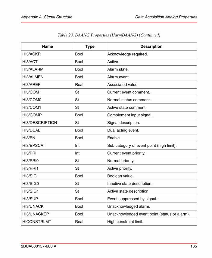
Appendix A Signal Structure Data Acquisition Analog Properties
3BUA000157-600 A 165
HI3/ACKR Bool Acknowledge required.
HI3/ACT Bool Active.
HI3/ALARM Bool Alarm state.
HI3/ALMEN Bool Alarm event.
HI3/AREF Real Associated value.
HI3/COM St Current event comment.
HI3/COM0 St Normal status comment.
HI3/COM1 St Active state comment.
HI3/COMP Bool Complement input signal.
HI3/DESCRIPTION St Signal description.
HI3/DUAL Bool Dual acting event.
HI3/EN Bool Enable.
HI3/EPSCAT Int Sub category of event point (high limit).
HI3/PRI Int Current event priority.
HI3/PRI0 St Normal priority.
HI3/PRI1 St Active priority.
HI3/SIG Bool Boolean value.
HI3/SIG0 St Inactive state description.
HI3/SIG1 St Active state description.
HI3/SUP Bool Event suppressed by signal.
HI3/UNACK Bool Unacknowledged alarm.
HI3/UNACKEP Bool Unacknowledged event point (status or alarm).
HICONSTRLMT Real High constraint limit.
Table 23. DAANG Properties (HarmDAANG) (Continued)
Name Type Description

Data Acquisition Analog Properties Appendix A Signal Structure
166 3BUA000157-600 A
HIGHDEV/ACKR Bool Acknowledge required.
HIGHDEV/ACT Bool Active.
HIGHDEV/ALARM Bool Alarm state.
HIGHDEV/ALMEN Bool Alarm event.
HIGHDEV/AREF Real Associated value.
HIGHDEV/COM St Current event comment.
HIGHDEV/COM0 St Normal status comment.
HIGHDEV/COM1 St Active state comment.
HIGHDEV/COMP Bool Complement input signal.
HIGHDEV/DESCRIPTION St Signal description.
HIGHDEV/DUAL Bool Dual acting event.
HIGHDEV/EN Bool Enable.
HIGHDEV/EPSCAT Int Sub category of event point (high limit).
HIGHDEV/PRI Int Current event priority.
HIGHDEV/PRI0 St Normal priority.
HIGHDEV/PRI1 St Active priority.
HIGHDEV/SIG Bool Boolean value.
HIGHDEV/SIG0 St Inactive state description.
HIGHDEV/SIG1 St Active state description
HIGHDEV/SUP Bool Event suppressed by signal.
HIGHDEV/UNACK Bool Unacknowledged alarm.
HIGHDEV/UNACKEP Bool Unacknowledged event point (status or alarm).
HIGHRATE/ACKR Bool Acknowledge required.
Table 23. DAANG Properties (HarmDAANG) (Continued)
Name Type Description

Appendix A Signal Structure Data Acquisition Analog Properties
3BUA000157-600 A 167
HIGHRATE/ACT Bool Active.
HIGHRATE/ALARM Bool Alarm state.
HIGHRATE/ALMEN Bool Alarm event.
HIGHRATE/AREF Real Associated value.
HIGHRATE/COM St Current event comment.
HIGHRATE/COM0 St Normal status comment.
HIGHRATE/COM1 St Active state comment.
HIGHRATE/COMP Bool Complement input signal.
HIGHRATE/DESCRIPTION St Signal description.
HIGHRATE/DUAL Bool Dual acting event.
HIGHRATE/EN Bool Enable.
HIGHRATE/EPSCAT Int Sub category of event point (high limit).
HIGHRATE/PACK Bool Event page wide acknowledge enable.
HIGHRATE/PRI Int Current event priority.
HIGHRATE/PRI0 Int Normal priority.
HIGHRATE/PRI1 Int Active priority.
HIGHRATE/SIG Bool Boolean value.
HIGHRATE/SIG0 St Inactive state description.
HIGHRATE/SIG1 St Active state description.
HIGHRATE/SUP Bool Event suppressed by signal.
HIGHRATE/UNACK Bool Unacknowledged alarm.
HIGHRATE/UNACKEP Bool Unacknowledged event point (status or alarm).
HIREF Real High reference limit.
Table 23. DAANG Properties (HarmDAANG) (Continued)
Name Type Description
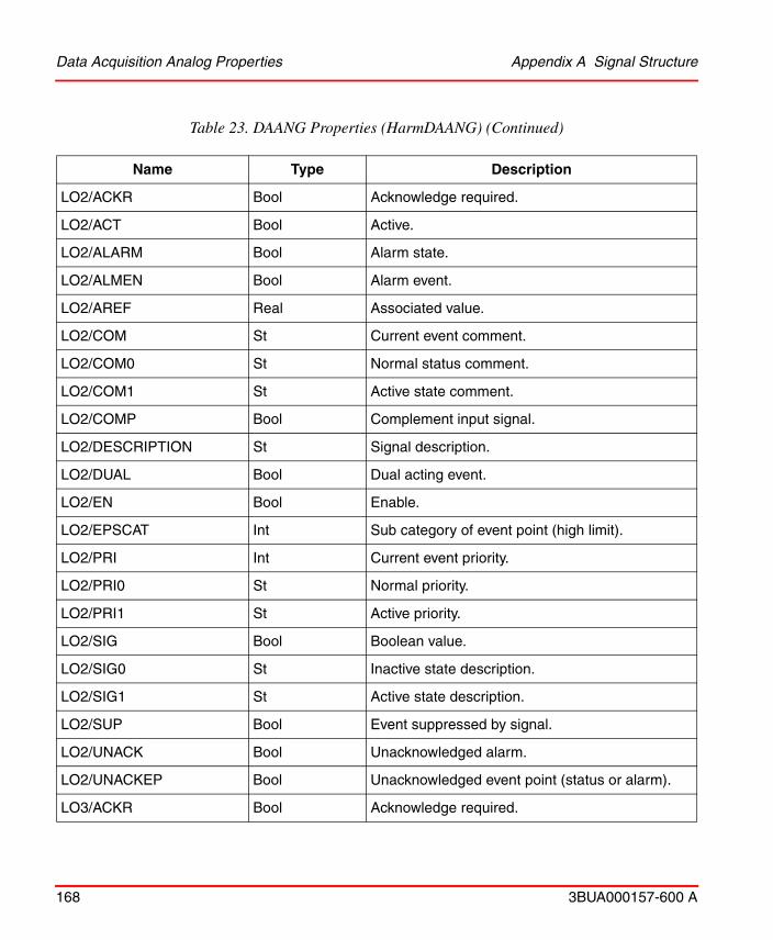
Data Acquisition Analog Properties Appendix A Signal Structure
168 3BUA000157-600 A
LO2/ACKR Bool Acknowledge required.
LO2/ACT Bool Active.
LO2/ALARM Bool Alarm state.
LO2/ALMEN Bool Alarm event.
LO2/AREF Real Associated value.
LO2/COM St Current event comment.
LO2/COM0 St Normal status comment.
LO2/COM1 St Active state comment.
LO2/COMP Bool Complement input signal.
LO2/DESCRIPTION St Signal description.
LO2/DUAL Bool Dual acting event.
LO2/EN Bool Enable.
LO2/EPSCAT Int Sub category of event point (high limit).
LO2/PRI Int Current event priority.
LO2/PRI0 St Normal priority.
LO2/PRI1 St Active priority.
LO2/SIG Bool Boolean value.
LO2/SIG0 St Inactive state description.
LO2/SIG1 St Active state description.
LO2/SUP Bool Event suppressed by signal.
LO2/UNACK Bool Unacknowledged alarm.
LO2/UNACKEP Bool Unacknowledged event point (status or alarm).
LO3/ACKR Bool Acknowledge required.
Table 23. DAANG Properties (HarmDAANG) (Continued)
Name Type Description
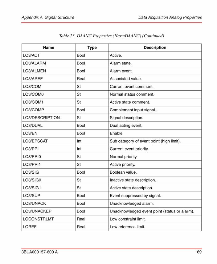
Appendix A Signal Structure Data Acquisition Analog Properties
3BUA000157-600 A 169
LO3/ACT Bool Active.
LO3/ALARM Bool Alarm state.
LO3/ALMEN Bool Alarm event.
LO3/AREF Real Associated value.
LO3/COM St Current event comment.
LO3/COM0 St Normal status comment.
LO3/COM1 St Active state comment.
LO3/COMP Bool Complement input signal.
LO3/DESCRIPTION St Signal description.
LO3/DUAL Bool Dual acting event.
LO3/EN Bool Enable.
LO3/EPSCAT Int Sub category of event point (high limit).
LO3/PRI Int Current event priority.
LO3/PRI0 St Normal priority.
LO3/PRI1 St Active priority.
LO3/SIG Bool Boolean value.
LO3/SIG0 St Inactive state description.
LO3/SIG1 St Active state description.
LO3/SUP Bool Event suppressed by signal.
LO3/UNACK Bool Unacknowledged alarm.
LO3/UNACKEP Bool Unacknowledged event point (status or alarm).
LOCONSTRLMT Real Low constraint limit.
LOREF Real Low reference limit.
Table 23. DAANG Properties (HarmDAANG) (Continued)
Name Type Description
Data Acquisition Analog Properties Appendix A Signal Structure
170 3BUA000157-600 A
LOWDEV/ACKR Bool Acknowledge required.
LOWDEV/ACT Bool Active.
LOWDEV/ALARM Bool Alarm state.
LOWDEV/ALMEN Bool Alarm event.
LOWDEV/AREF Real Associated value.
LOWDEV/COM St Current event comment.
LOWDEV/COM0 St Normal status comment.
LOWDEV/COM1 St Active state comment.
LOWDEV/COMP Bool Complement input signal.
LOWDEV/DESCRIPTION St Signal description.
LOWDEV/DUAL Bool Dual acting event.
LOWDEV/EN Bool Enable.
LOWDEV/EPSCAT Int Sub category of event point (high limit).
LOWDEV/PRI Int Current event priority.
LOWDEV/PRI0 St Normal priority.
LOWDEV/PRI1 St Active priority.
LOWDEV/SIG Bool Boolean value.
LOWDEV/SIG0 St Inactive state description.
LOWDEV/SIG1 St Active state description.
LOWDEV/SUP Bool Event suppressed by signal.
LOWDEV/UNACK Bool Unacknowledged alarm.
LOWDEV/UNACKEP Bool Unacknowledged event point (status or alarm).
LOWRATE/ACKR Bool Acknowledge required.
Table 23. DAANG Properties (HarmDAANG) (Continued)
Name Type Description
Appendix A Signal Structure Data Acquisition Analog Properties
3BUA000157-600 A 171
LOWRATE/ACT Bool Active.
LOWRATE/ALARM Bool Alarm state.
LOWRATE/ALMEN Bool Alarm event.
LOWRATE/AREF Real Associated value.
LOWRATE/COM St Current event comment.
LOWRATE/COM0 St Normal status comment.
LOWRATE/COM1 St Active state comment.
LOWRATE/COMP Bool Complement input signal.
LOWRATE/DESCRIPTION St Signal description.
LOWRATE/DUAL Bool Dual acting event.
LOWRATE/EN Bool Enable.
LOWRATE/EPSCAT Int Sub category of event point (high limit).
LOWRATE/PRI Int Current event priority.
LOWRATE/PRI0 St Normal priority.
LOWRATE/PRI1 St Active priority.
LOWRATE/SIG Bool Boolean value.
LOWRATE/SIG0 St Inactive state description.
LOWRATE/SIG1 St Active state description.
LOWRATE/SUP Bool Event suppressed by signal.
LOWRATE/UNACK Bool Unacknowledged alarm.
LOWRATE/UNACKEP Bool Unacknowledged event point (status or alarm).
MULTLVL Bool Multilevel alarming enabled.
NOREPORT Bool Scanning disabled by blockware.
Table 23. DAANG Properties (HarmDAANG) (Continued)
Name Type Description

Enhanced Analog Input/Output Properties Appendix A Signal Structure
172 3BUA000157-600 A
Enhanced Analog Input/Output Properties
The Enhanced Analog in tag contains all the properties listed in Table 22 and Table 24. The Enhanced Analog out tag contains all the properties listed in Table 22, and Table 25.
NXTHILMT Real Next higher alarm limit.
NXTLOLMT Real Next lower alarm limit.
OUTRANGE Bool Value is out of range.
PERINSEL Bool User is permitted to select input value.
QUALOVR Bool Quality is overridden by blockware.
RATEALM Bool Rate alarm summary.
REALM Bool Periodic realarming enabled.
REDTAG/ACT Bool Red tagging is active.
REDTAG/KEY1 St Red tag key 1.
REDTAG/KEY2 St Red tag key 2.
REDTAG/KEY3 St Red tag key 3.
SRC Int Composite mode (AUTO and ALTINSEL).
USERVAL Real Manually entered value.
VARALM Bool Variable alarming enabled.
Table 24. Enhanced Analog In Properties (HarmEnhAnaIn)
Name Type Description
AUTO Bool Override enable.
CONFERR Int Configuration error.
Table 23. DAANG Properties (HarmDAANG) (Continued)
Name Type Description

Appendix A Signal Structure Enhanced Analog Input/Output Properties
3BUA000157-600 A 173
CURRLEN Int Current message length.
EUCHG Real Engineering units significant change.
EXTRANGE Int External range.
INPTYPE Int Input type.
LABEL St Channel label.
ORIGLEN Int Original message length.
OVRENBL Bool Override enabled.
OVRVAL Real Override value.
PROPQUAL Int Propagated quality.
RANGE Int Range: 00=OK, 01=open, 10=short, 11=overdrive.
RDBKSTS Int Read back status.
REFSTS Int Reference status.
SEIMODE Int Status error inhibit mode.
SIM Bool Simulation enable.
SIMBLK Int Simulation value block number.
SUSPERR Int Suspect error.
TRUNC Bool True if message was truncated remotely.
Table 25. Enhanced Analog Out Properties (HarmEnhAnaOut)
Name Type Description
AUTO Bool Override enable.
CONFERR Int Configuration error.
CURRLEN Int Current message length.
Table 24. Enhanced Analog In Properties (HarmEnhAnaIn) (Continued)
Name Type Description
Station Properties Appendix A Signal Structure
174 3BUA000157-600 A
Station Properties
The Station tag contains all the properties listed in Table 22 and Table 26.
EUCHG Real Engineering units significant change.
EXTRANGE Int External range.
LABEL St Channel label.
ORIGLEN Int Original message length.
OVRENBL Bool Override enabled.
OVRVAL Real Override value.
PROPQUAL Int Propagated quality.
RANGE Int Range: 00=OK, 01=open, 10=short, 11=overdrive.
RDBKSTS Int Read back status.
REFSTS Int Reference status.
SEIMODE Int Status error inhibit mode.
SIM Bool Simulation enable.
SIMBLK Int Simulation value block number.
SUSPERR Int Suspect error.
TRUNC Bool True if message was truncated remotely.
Table 26. Station Properties (HarmStation)
Name Type Description
AUTO Bool Station mode.
BYPASS Bool Control output is bypassed.
Table 25. Enhanced Analog Out Properties (HarmEnhAnaOut) (Continued)
Name Type Description

Appendix A Signal Structure Station Properties
3BUA000157-600 A 175
CMPTRSTS Bool Computer signal is OK.
CO/DESCRIPTION St Signal description.
CO/FOR Int Formatting information.
CO/HIGH Real High range of signal.
CO/LOW Real Low range of signal.
CO/PERCENT Real Signal (SIG) as a percentage of span.
CO/SIG Real Analog value.
CO/SIG:QS St Quality string.
CO/SPAN Real Difference between low and high ranges.
CO/UNITS St Engineering units.
DEVALM Bool Deviation alarm summary.
DEVLIM/DESCRIPTION St Signal description.
DEVLIM/FOR Int Formatting information.
DEVLIM/HIGH Real High range of signal.
DEVLIM/LOW Real Low range of signal.
DEVLIM/PERCENT Real Signal (SIG) as a percentage of span.
DEVLIM/SIG Real Analog value.
DEVLIM/SPAN Real Difference between low and high ranges.
DEVLIM/UNITS St Engineering units.
HIGHDEV/ACKR Bool Acknowledge required.
HIGHDEV/ACT Bool Active.
HIGHDEV/ALARM Bool Alarm state.
HIGHDEV/ALMEN Bool Alarm event.
Table 26. Station Properties (HarmStation) (Continued)
Name Type Description

Station Properties Appendix A Signal Structure
176 3BUA000157-600 A
HIGHDEV/AREF Real Associated value.
HIGHDEV/COM St Current event comment.
HIGHDEV/COM0 St Normal status comment.
HIGHDEV/COM1 St Active state comment.
HIGHDEV/COMP Bool Complement input signal.
HIGHDEV/DESCRIPTION St Signal description.
HIGHDEV/DUAL Bool Dual acting event.
HIGHDEV/EN Bool Enable.
HIGHDEV/EPSCAT Int Sub category of event point (high limit).
HIGHDEV/PRI Int Current event priority
HIGHDEV/PRI0 St Normal priority.
HIGHDEV/PRI1 St Active priority.
HIGHDEV/SIG Bool Boolean value.
HIGHDEV/SIG0 St Inactive state description
HIGHDEV/SIG1 St Active state description.
HIGHDEV/SUP Bool Event suppressed by signal.
HIGHDEV/UNACK Bool Unacknowledged alarm.
HIGHDEV/UNACKEP Bool Unacknowledged event point (status or alarm).
LOWDEV/ACKR Bool Acknowledge required.
LOWDEV/ACT Bool Active.
LOWDEV/ALARM Bool Alarm state.
LOWDEV/ALMEN Bool Alarm event.
LOWDEV/AREF Real Associated value.
Table 26. Station Properties (HarmStation) (Continued)
Name Type Description

Appendix A Signal Structure Station Properties
3BUA000157-600 A 177
LOWDEV/COM St Current event comment.
LOWDEV/COM0 St Normal status comment.
LOWDEV/COM1 St Active state comment.
LOWDEV/COMP Bool Complement input signal.
LOWDEV/DESCRIPTION St Signal description.
LOWDEV/DUAL Bool Dual acting event.
LOWDEV/EN Bool Enable.
LOWDEV/EPSCAT Int Sub category of event point (high limit).
LOWDEV/PRI Int Current event priority.
LOWDEV/PRI0 St Normal priority.
LOWDEV/PRI1 St Active priority.
LOWDEV/SIG Bool Boolean value.
LOWDEV/SIG0 St Inactive state description.
LOWDEV/SIG1 St Active state description.
LOWDEV/SUP Bool Event suppressed by signal.
LOWDEV/UNACK Bool Unacknowledged alarm.
LOWDEV/UNACKEP Bool Unacknowledged event point (status or alarm).
MODELOCK Bool Module has mode locked.
OUTSTS Bool Hand held Station has failed.
OUTTRACKING Bool Output is tracking an input value.
RATIO Real Ratio index.
RATIO:QS St Quality string.
REDTAG/ACT Bool Red tagging is active.
Table 26. Station Properties (HarmStation) (Continued)
Name Type Description

Station Properties Appendix A Signal Structure
178 3BUA000157-600 A
REDTAG/KEY1 St Red tag key 1.
REDTAG/KEY2 St Red tag key 2.
REDTAG/KEY3 St Red tag key 3.
SP/DESCRIPTION St Signal description.
SP/FOR Int Formatting information.
SP/HIGH Real High range of signal.
SP/LOW Real Low range of signal.
SP/PERCENT Real Signal (SIG) as a percentage of span.
SP/SIG Real Analog value.
SP/SIG:QS St Quality string.
SP/SPAN Real Difference between low and high ranges.
SP/UNITS St Engineering units.
SPTRACKING Bool SP tracking enabled.
STNLVL Bool Station is under computer control.
STNMODE Bool Cascade or ratio mode selected.
STNTYPE UInt Station type.
STNTYPE:S St Text version of quality.
TUNEBLK Int Block number of feedback’s tuning block.
Table 26. Station Properties (HarmStation) (Continued)
Name Type Description
Appendix A Signal Structure Remote Manual Set Constant Properties
3BUA000157-600 A 179
Remote Manual Set Constant PropertiesThe RMSC tag contains all the properties listed in Table 22 and Table 27.
Common Digital PropertiesTable 28 through Table 35 list all the specific properties to each of the Digital tag types. Table 28 lists the Common Digital properties. These are also the properties
Table 27. RMSC Properties (HarmRMSC)
Name Type Description
ALMACKBC Bool Broadcast alarm acknowledge events.
OPHILM Real High limit value.
OPLOLM Real Low limit value.
PV/DESCRIPTION St Signal description.
PV/FOR Int Formatting information.
PV/HIGH Real High range of signal.
PV/LOW Real Low range of signal.
PV/PERCENT Real Signal (SIG) as a percentage of span.
PV/SIG Real Analog value.
PV/SIG:QS St Quality string.
PV/SPAN Real Difference between low and high ranges.
PV/UNITS St Engineering units.
TRACKING Bool Value is tracking an input value.
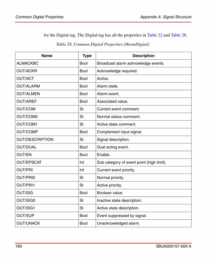
Common Digital Properties Appendix A Signal Structure
180 3BUA000157-600 A
for the Digital tag. The Digital tag has all the properties in Table 22 and Table 28.
Table 28. Common Digital Properties (HarmDigital)
Name Type Description
ALMACKBC Bool Broadcast alarm acknowledge events.
OUT/ACKR Bool Acknowledge required.
OUT/ACT Bool Active.
OUT/ALARM Bool Alarm state.
OUT/ALMEN Bool Alarm event.
OUT/AREF Bool Associated value.
OUT/COM St Current event comment.
OUT/COM0 St Normal status comment.
OUT/COM1 St Active state comment.
OUT/COMP Bool Complement input signal.
OUT/DESCRIPTION St Signal description.
OUT/DUAL Bool Dual acting event.
OUT/EN Bool Enable.
OUT/EPSCAT Int Sub category of event point (high limit).
OUT/PRI Int Current event priority.
OUT/PRI0 St Normal priority.
OUT/PRI1 St Active priority.
OUT/SIG Bool Boolean value.
OUT/SIG0 St Inactive state description.
OUT/SIG1 St Active state description.
OUT/SUP Bool Event suppressed by signal.
OUT/UNACK Bool Unacknowledged alarm.
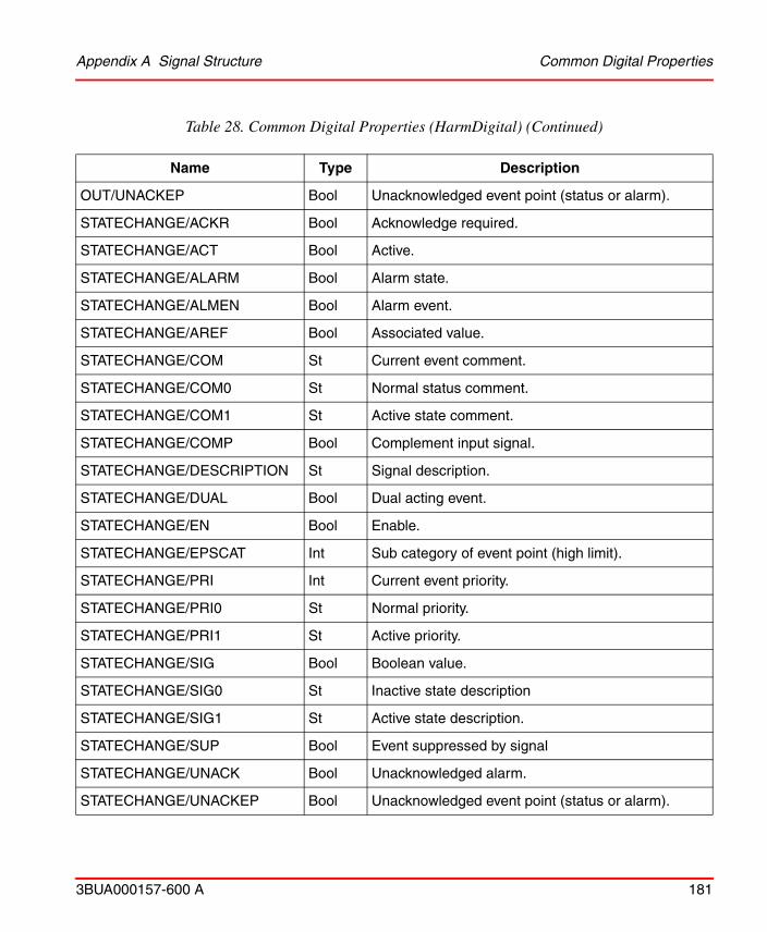
Appendix A Signal Structure Common Digital Properties
3BUA000157-600 A 181
OUT/UNACKEP Bool Unacknowledged event point (status or alarm).
STATECHANGE/ACKR Bool Acknowledge required.
STATECHANGE/ACT Bool Active.
STATECHANGE/ALARM Bool Alarm state.
STATECHANGE/ALMEN Bool Alarm event.
STATECHANGE/AREF Bool Associated value.
STATECHANGE/COM St Current event comment.
STATECHANGE/COM0 St Normal status comment.
STATECHANGE/COM1 St Active state comment.
STATECHANGE/COMP Bool Complement input signal.
STATECHANGE/DESCRIPTION St Signal description.
STATECHANGE/DUAL Bool Dual acting event.
STATECHANGE/EN Bool Enable.
STATECHANGE/EPSCAT Int Sub category of event point (high limit).
STATECHANGE/PRI Int Current event priority.
STATECHANGE/PRI0 St Normal priority.
STATECHANGE/PRI1 St Active priority.
STATECHANGE/SIG Bool Boolean value.
STATECHANGE/SIG0 St Inactive state description
STATECHANGE/SIG1 St Active state description.
STATECHANGE/SUP Bool Event suppressed by signal
STATECHANGE/UNACK Bool Unacknowledged alarm.
STATECHANGE/UNACKEP Bool Unacknowledged event point (status or alarm).
Table 28. Common Digital Properties (HarmDigital) (Continued)
Name Type Description
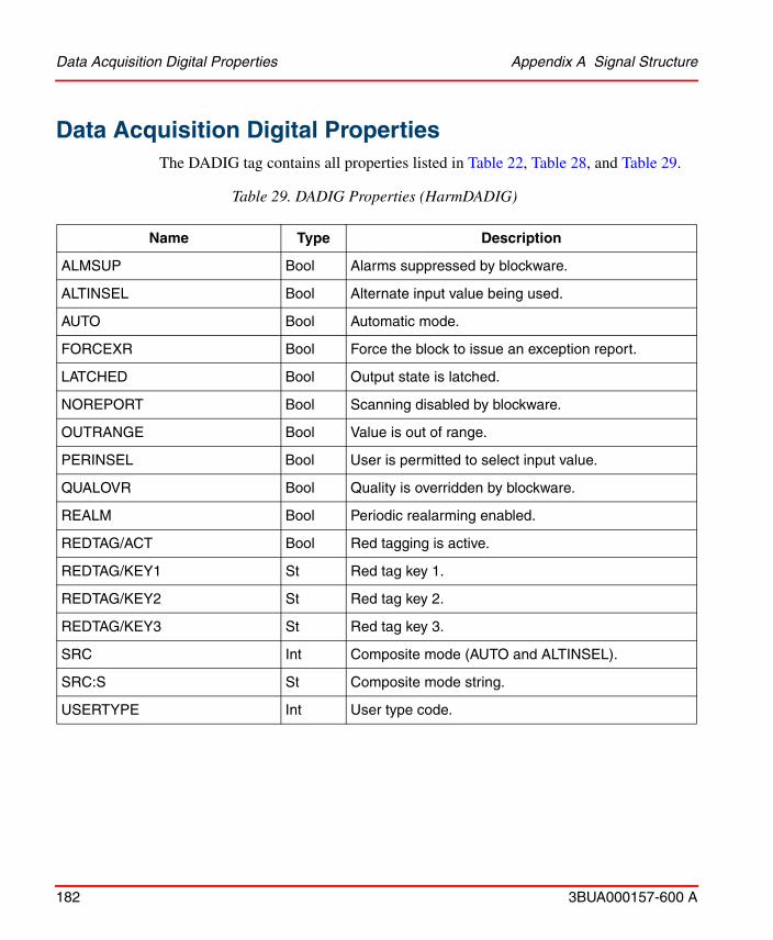
Data Acquisition Digital Properties Appendix A Signal Structure
182 3BUA000157-600 A
Data Acquisition Digital PropertiesThe DADIG tag contains all properties listed in Table 22, Table 28, and Table 29.
Table 29. DADIG Properties (HarmDADIG)
Name Type Description
ALMSUP Bool Alarms suppressed by blockware.
ALTINSEL Bool Alternate input value being used.
AUTO Bool Automatic mode.
FORCEXR Bool Force the block to issue an exception report.
LATCHED Bool Output state is latched.
NOREPORT Bool Scanning disabled by blockware.
OUTRANGE Bool Value is out of range.
PERINSEL Bool User is permitted to select input value.
QUALOVR Bool Quality is overridden by blockware.
REALM Bool Periodic realarming enabled.
REDTAG/ACT Bool Red tagging is active.
REDTAG/KEY1 St Red tag key 1.
REDTAG/KEY2 St Red tag key 2.
REDTAG/KEY3 St Red tag key 3.
SRC Int Composite mode (AUTO and ALTINSEL).
SRC:S St Composite mode string.
USERTYPE Int User type code.
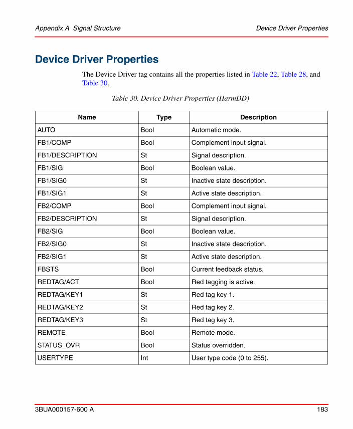
Appendix A Signal Structure Device Driver Properties
3BUA000157-600 A 183
Device Driver PropertiesThe Device Driver tag contains all the properties listed in Table 22, Table 28, and Table 30.
Table 30. Device Driver Properties (HarmDD)
Name Type Description
AUTO Bool Automatic mode.
FB1/COMP Bool Complement input signal.
FB1/DESCRIPTION St Signal description.
FB1/SIG Bool Boolean value.
FB1/SIG0 St Inactive state description.
FB1/SIG1 St Active state description.
FB2/COMP Bool Complement input signal.
FB2/DESCRIPTION St Signal description.
FB2/SIG Bool Boolean value.
FB2/SIG0 St Inactive state description.
FB2/SIG1 St Active state description.
FBSTS Bool Current feedback status.
REDTAG/ACT Bool Red tagging is active.
REDTAG/KEY1 St Red tag key 1.
REDTAG/KEY2 St Red tag key 2.
REDTAG/KEY3 St Red tag key 3.
REMOTE Bool Remote mode.
STATUS_OVR Bool Status overridden.
USERTYPE Int User type code (0 to 255).
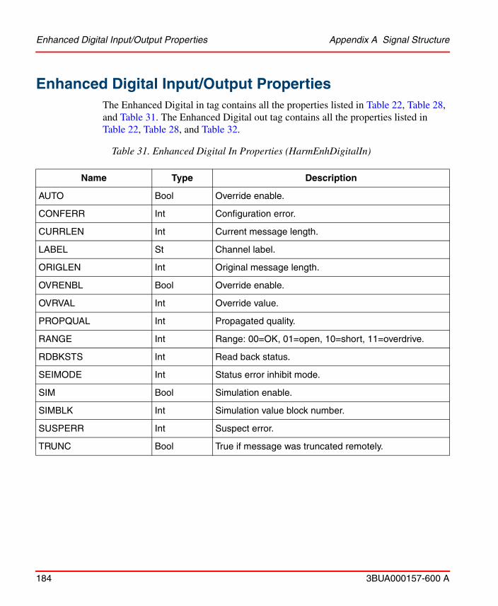
Enhanced Digital Input/Output Properties Appendix A Signal Structure
184 3BUA000157-600 A
Enhanced Digital Input/Output PropertiesThe Enhanced Digital in tag contains all the properties listed in Table 22, Table 28, and Table 31. The Enhanced Digital out tag contains all the properties listed in Table 22, Table 28, and Table 32.
Table 31. Enhanced Digital In Properties (HarmEnhDigitalIn)
Name Type Description
AUTO Bool Override enable.
CONFERR Int Configuration error.
CURRLEN Int Current message length.
LABEL St Channel label.
ORIGLEN Int Original message length.
OVRENBL Bool Override enable.
OVRVAL Int Override value.
PROPQUAL Int Propagated quality.
RANGE Int Range: 00=OK, 01=open, 10=short, 11=overdrive.
RDBKSTS Int Read back status.
SEIMODE Int Status error inhibit mode.
SIM Bool Simulation enable.
SIMBLK Int Simulation value block number.
SUSPERR Int Suspect error.
TRUNC Bool True if message was truncated remotely.
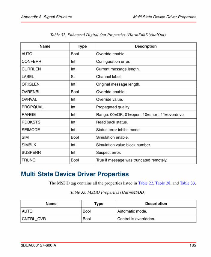
Appendix A Signal Structure Multi State Device Driver Properties
3BUA000157-600 A 185
Multi State Device Driver Properties
The MSDD tag contains all the properties listed in Table 22, Table 28, and Table 33.
Table 32. Enhanced Digital Out Properties (HarmEnhDigitalOut)
Name Type Description
AUTO Bool Override enable.
CONFERR Int Configuration error.
CURRLEN Int Current message length.
LABEL St Channel label.
ORIGLEN Int Original message length.
OVRENBL Bool Override enable.
OVRVAL Int Override value.
PROPQUAL Int Propagated quality
RANGE Int Range: 00=OK, 01=open, 10=short, 11=overdrive.
RDBKSTS Int Read back status.
SEIMODE Int Status error inhibit mode.
SIM Bool Simulation enable.
SIMBLK Int Simulation value block number.
SUSPERR Int Suspect error.
TRUNC Bool True if message was truncated remotely.
Table 33. MSDD Properties (HarmMSDD)
Name Type Description
AUTO Bool Automatic mode.
CNTRL_OVR Bool Control is overridden.

Multi State Device Driver Properties Appendix A Signal Structure
186 3BUA000157-600 A
FB1/COMP Bool Complement input signal.
FB1/DESCRIPTION St Signal description.
FB1/SIG Bool Boolean value.
FB1/SIG0 St Inactive state description.
FB1/SIG1 St Active state description.
FB2/COMP Bool Complement input signal.
FB2/DESCRIPTION St Signal description.
FB2/SIG Bool Boolean value.
FB2/SIG0 St Inactive state description.
FB2/SIG1 St Active state description.
FB3/COMP Bool Complement input signal.
FB3/DESCRIPTION St Signal description.
FB3/SIG Bool Boolean value.
FB3/SIG0 St Inactive state description.
FB3/SIG1 St Active state description.
FB4/COMP Bool Complement input signal.
FB4/DESCRIPTION St Signal description.
FB4/SIG Bool Boolean value.
FB4/SIG0 St Inactive state description
FB4/SIG1 St Active state description.
LASTGOOD Int Last good state.
LASTGOOD:S St Text version of last good state.
LS0 St State 0 logic state description.
Table 33. MSDD Properties (HarmMSDD) (Continued)
Name Type Description

Appendix A Signal Structure Remote Control Memory Properties
3BUA000157-600 A 187
Remote Control Memory PropertiesThe RCM tag contains all the properties listed in Table 22, Table 28, and Table 34.
LS1 St State 1 logic state description.
LS2 St State 2 logic state description.
LS3 St State 3 logic state description.
REDTAG/ACT Bool Red tagging is active.
REDTAG/KEY1 St Red tag key 1.
REDTAG/KEY2 St Red tag key 2.
REDTAG/KEY3 St Red tag key 3.
SP Int Requested state.
STATUS_OVR Bool Status overridden.
USERTYPE Int User type code (0 to 255).
Table 34. RCM Properties (HarmRCM)
Name Type Description
FB1/COMP Bool Complement input signal.
FB1/DESCRIPTION St Signal description.
FB1/SIG Bool Boolean value.
FB1/SIG0 St Inactive state description.
FB1/SIG1 St Active state description.
OUTOVR Bool State is overridden.
REDTAG/ACT Bool Red tagging is active.
Table 33. MSDD Properties (HarmMSDD) (Continued)
Name Type Description
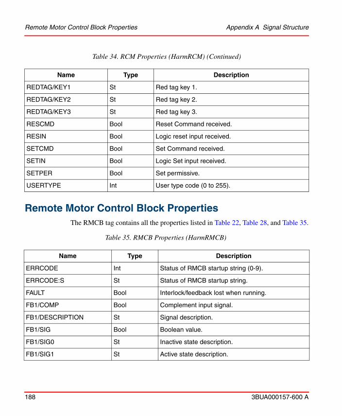
Remote Motor Control Block Properties Appendix A Signal Structure
188 3BUA000157-600 A
Remote Motor Control Block PropertiesThe RMCB tag contains all the properties listed in Table 22, Table 28, and Table 35.
REDTAG/KEY1 St Red tag key 1.
REDTAG/KEY2 St Red tag key 2.
REDTAG/KEY3 St Red tag key 3.
RESCMD Bool Reset Command received.
RESIN Bool Logic reset input received.
SETCMD Bool Set Command received.
SETIN Bool Logic Set input received.
SETPER Bool Set permissive.
USERTYPE Int User type code (0 to 255).
Table 35. RMCB Properties (HarmRMCB)
Name Type Description
ERRCODE Int Status of RMCB startup string (0-9).
ERRCODE:S St Status of RMCB startup string.
FAULT Bool Interlock/feedback lost when running.
FB1/COMP Bool Complement input signal.
FB1/DESCRIPTION St Signal description.
FB1/SIG Bool Boolean value.
FB1/SIG0 St Inactive state description.
FB1/SIG1 St Active state description.
Table 34. RCM Properties (HarmRCM) (Continued)
Name Type Description
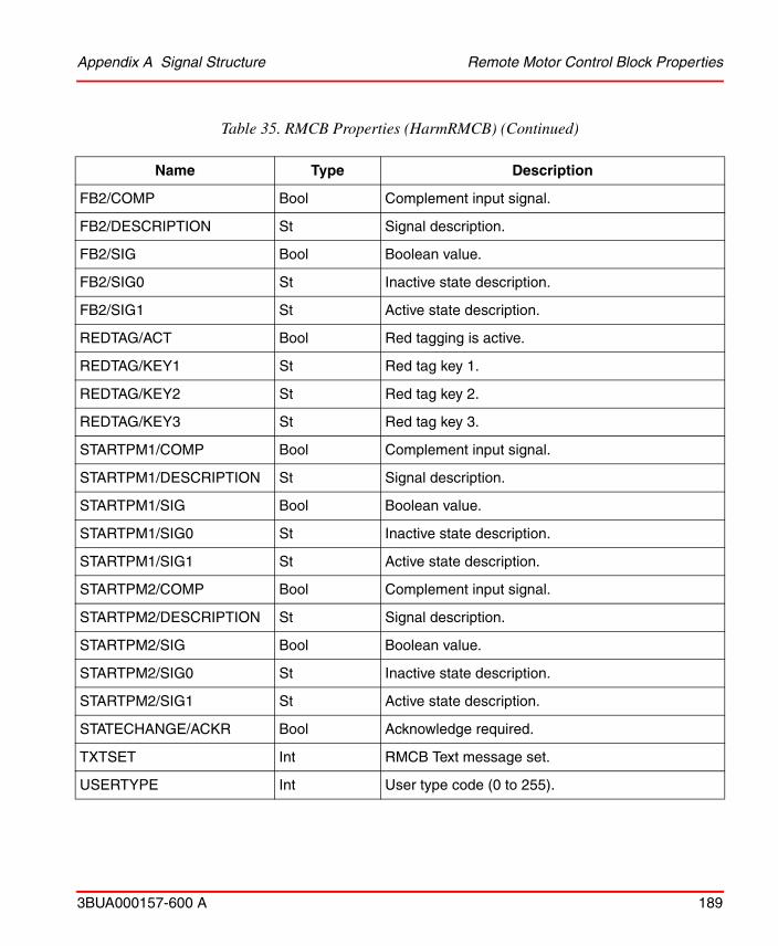
Appendix A Signal Structure Remote Motor Control Block Properties
3BUA000157-600 A 189
FB2/COMP Bool Complement input signal.
FB2/DESCRIPTION St Signal description.
FB2/SIG Bool Boolean value.
FB2/SIG0 St Inactive state description.
FB2/SIG1 St Active state description.
REDTAG/ACT Bool Red tagging is active.
REDTAG/KEY1 St Red tag key 1.
REDTAG/KEY2 St Red tag key 2.
REDTAG/KEY3 St Red tag key 3.
STARTPM1/COMP Bool Complement input signal.
STARTPM1/DESCRIPTION St Signal description.
STARTPM1/SIG Bool Boolean value.
STARTPM1/SIG0 St Inactive state description.
STARTPM1/SIG1 St Active state description.
STARTPM2/COMP Bool Complement input signal.
STARTPM2/DESCRIPTION St Signal description.
STARTPM2/SIG Bool Boolean value.
STARTPM2/SIG0 St Inactive state description.
STARTPM2/SIG1 St Active state description.
STATECHANGE/ACKR Bool Acknowledge required.
TXTSET Int RMCB Text message set.
USERTYPE Int User type code (0 to 255).
Table 35. RMCB Properties (HarmRMCB) (Continued)
Name Type Description
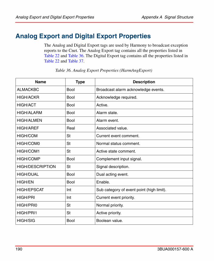
Analog Export and Digital Export Properties Appendix A Signal Structure
190 3BUA000157-600 A
Analog Export and Digital Export PropertiesThe Analog and Digital Export tags are used by Harmony to broadcast exception reports to the Cnet. The Analog Export tag contains all the properties listed in Table 22 and Table 36. The Digital Export tag contains all the properties listed in Table 22 and Table 37.
Table 36. Analog Export Properties (HarmAngExport)
Name Type Description
ALMACKBC Bool Broadcast alarm acknowledge events.
HIGH/ACKR Bool Acknowledge required.
HIGH/ACT Bool Active.
HIGH/ALARM Bool Alarm state.
HIGH/ALMEN Bool Alarm event.
HIGH/AREF Real Associated value.
HIGH/COM St Current event comment.
HIGH/COM0 St Normal status comment.
HIGH/COM1 St Active state comment.
HIGH/COMP Bool Complement input signal.
HIGH/DESCRIPTION St Signal description.
HIGH/DUAL Bool Dual acting event.
HIGH/EN Bool Enable.
HIGH/EPSCAT Int Sub category of event point (high limit).
HIGH/PRI Int Current event priority.
HIGH/PRI0 St Normal priority.
HIGH/PRI1 St Active priority.
HIGH/SIG Bool Boolean value.

Appendix A Signal Structure Analog Export and Digital Export Properties
3BUA000157-600 A 191
HIGH/SIG0 St Inactive state description.
HIGH/SIG1 St Active state description.
HIGH/SUP Bool Event suppressed by signal.
HIGH/UNACK Bool Unacknowledged alarm.
HIGH/UNACKEP Bool Unacknowledged event point (status or alarm).
HIGHLIM Real High alarm limit.
ICI_INDEX Int ICI Index to be used for exporting this tag.
LOW/ACKR Bool Acknowledge required.
LOW/ACT Bool Active.
LOW/ALARM Bool Alarm state.
LOW/ALMEN Bool Alarm event.
LOW/AREF Real Associated value.
LOW/COM St Current event comment.
LOW/COM0 St Normal status comment.
LOW/COM1 St Active state comment.
LOW/COMP Bool Complement input signal.
LOW/DESCRIP-TION St Signal description.
LOW/DUAL Bool Dual acting event.
LOW/EN Bool Enable.
LOW/EPSCAT Int Sub category of event point (high limit).
LOW/PRI Int Current event priority.
LOW/PRI0 St Normal priority.
LOW/PRI1 St Active priority.
Table 36. Analog Export Properties (HarmAngExport) (Continued)
Name Type Description
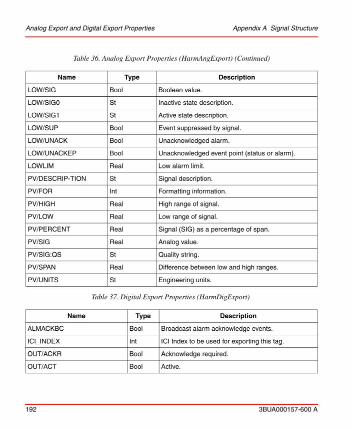
Analog Export and Digital Export Properties Appendix A Signal Structure
192 3BUA000157-600 A
LOW/SIG Bool Boolean value.
LOW/SIG0 St Inactive state description.
LOW/SIG1 St Active state description.
LOW/SUP Bool Event suppressed by signal.
LOW/UNACK Bool Unacknowledged alarm.
LOW/UNACKEP Bool Unacknowledged event point (status or alarm).
LOWLIM Real Low alarm limit.
PV/DESCRIP-TION St Signal description.
PV/FOR Int Formatting information.
PV/HIGH Real High range of signal.
PV/LOW Real Low range of signal.
PV/PERCENT Real Signal (SIG) as a percentage of span.
PV/SIG Real Analog value.
PV/SIG:QS St Quality string.
PV/SPAN Real Difference between low and high ranges.
PV/UNITS St Engineering units.
Table 37. Digital Export Properties (HarmDigExport)
Name Type Description
ALMACKBC Bool Broadcast alarm acknowledge events.
ICI_INDEX Int ICI Index to be used for exporting this tag.
OUT/ACKR Bool Acknowledge required.
OUT/ACT Bool Active.
Table 36. Analog Export Properties (HarmAngExport) (Continued)
Name Type Description
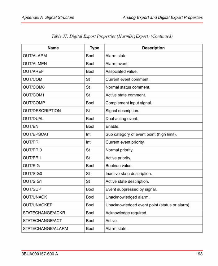
Appendix A Signal Structure Analog Export and Digital Export Properties
3BUA000157-600 A 193
OUT/ALARM Bool Alarm state.
OUT/ALMEN Bool Alarm event.
OUT/AREF Bool Associated value.
OUT/COM St Current event comment.
OUT/COM0 St Normal status comment.
OUT/COM1 St Active state comment.
OUT/COMP Bool Complement input signal.
OUT/DESCRIPTION St Signal description.
OUT/DUAL Bool Dual acting event.
OUT/EN Bool Enable.
OUT/EPSCAT Int Sub category of event point (high limit).
OUT/PRI Int Current event priority.
OUT/PRI0 St Normal priority.
OUT/PRI1 St Active priority.
OUT/SIG Bool Boolean value.
OUT/SIG0 St Inactive state description.
OUT/SIG1 St Active state description.
OUT/SUP Bool Event suppressed by signal.
OUT/UNACK Bool Unacknowledged alarm.
OUT/UNACKEP Bool Unacknowledged event point (status or alarm).
STATECHANGE/ACKR Bool Acknowledge required.
STATECHANGE/ACT Bool Active.
STATECHANGE/ALARM Bool Alarm state.
Table 37. Digital Export Properties (HarmDigExport) (Continued)
Name Type Description
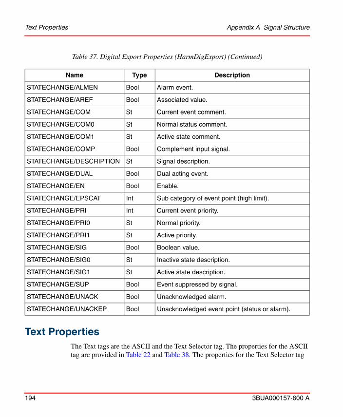
Text Properties Appendix A Signal Structure
194 3BUA000157-600 A
Text PropertiesThe Text tags are the ASCII and the Text Selector tag. The properties for the ASCII tag are provided in Table 22 and Table 38. The properties for the Text Selector tag
STATECHANGE/ALMEN Bool Alarm event.
STATECHANGE/AREF Bool Associated value.
STATECHANGE/COM St Current event comment.
STATECHANGE/COM0 St Normal status comment.
STATECHANGE/COM1 St Active state comment.
STATECHANGE/COMP Bool Complement input signal.
STATECHANGE/DESCRIPTION St Signal description.
STATECHANGE/DUAL Bool Dual acting event.
STATECHANGE/EN Bool Enable.
STATECHANGE/EPSCAT Int Sub category of event point (high limit).
STATECHANGE/PRI Int Current event priority.
STATECHANGE/PRI0 St Normal priority.
STATECHANGE/PRI1 St Active priority.
STATECHANGE/SIG Bool Boolean value.
STATECHANGE/SIG0 St Inactive state description.
STATECHANGE/SIG1 St Active state description.
STATECHANGE/SUP Bool Event suppressed by signal.
STATECHANGE/UNACK Bool Unacknowledged alarm.
STATECHANGE/UNACKEP Bool Unacknowledged event point (status or alarm).
Table 37. Digital Export Properties (HarmDigExport) (Continued)
Name Type Description
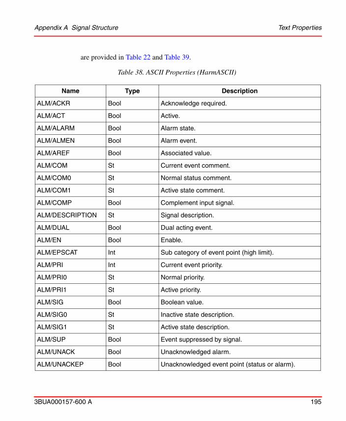
Appendix A Signal Structure Text Properties
3BUA000157-600 A 195
are provided in Table 22 and Table 39.
Table 38. ASCII Properties (HarmASCII)
Name Type Description
ALM/ACKR Bool Acknowledge required.
ALM/ACT Bool Active.
ALM/ALARM Bool Alarm state.
ALM/ALMEN Bool Alarm event.
ALM/AREF Bool Associated value.
ALM/COM St Current event comment.
ALM/COM0 St Normal status comment.
ALM/COM1 St Active state comment.
ALM/COMP Bool Complement input signal.
ALM/DESCRIPTION St Signal description.
ALM/DUAL Bool Dual acting event.
ALM/EN Bool Enable.
ALM/EPSCAT Int Sub category of event point (high limit).
ALM/PRI Int Current event priority.
ALM/PRI0 St Normal priority.
ALM/PRI1 St Active priority.
ALM/SIG Bool Boolean value.
ALM/SIG0 St Inactive state description.
ALM/SIG1 St Active state description.
ALM/SUP Bool Event suppressed by signal.
ALM/UNACK Bool Unacknowledged alarm.
ALM/UNACKEP Bool Unacknowledged event point (status or alarm).

Text Properties Appendix A Signal Structure
196 3BUA000157-600 A
ALMACKBC Bool Broadcast alarm acknowledge events.
ALMSUP Bool Alarm suppressed by blockware.
AUTO Bool Automatic mode.
BLKLEN Int Maximum length of data string from blockware.
CNTRLPER Bool Operator control enabled.
LEN Int Maximum length of data strings.
LOCTRUNC Bool Local truncation occurred.
MODELOCK Bool Blockware will not accept a mode change.
NAK Bool Blockware has rejected data.
ORIGLEN Int Length of data originally sent.
PDT_ECHO Bool Blockware has echoed data.
QUALOVR Bool Blockware is overriding the quality status.
RCV_LEN Int Length of data finally received.
REALM Bool Periodically realarm.
REDTAG/ACT Bool Red tagging is active.
REDTAG/KEY1 St Red tag key 1.
REDTAG/KEY2 St Red tag key 2.
REDTAG/KEY3 St Red tag key 3.
SEQ_NUM Int UDXR sequence number.
SET_PRIO Int Alarm priority of last control action.
SIG St Text signal (data string).
STR_LOCK Bool Blockware will not accept data.
TRUNC Bool Remote truncation occurred.
Table 38. ASCII Properties (HarmASCII) (Continued)
Name Type Description
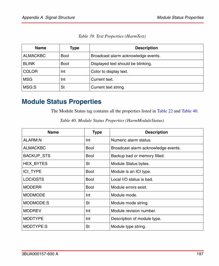
Appendix A Signal Structure Module Status Properties
3BUA000157-600 A 197
Module Status Properties
The Module Status tag contains all the properties listed in Table 22 and Table 40.
Table 39. Text Properties (HarmText)
Name Type Description
ALMACKBC Bool Broadcast alarm acknowledge events.
BLINK Bool Displayed text should be blinking.
COLOR Int Color to display text.
MSG Int Current text.
MSG:S St Current text string.
Table 40. Module Status Properties (HarmModuleStatus)
Name Type Description
ALARM:N Int Numeric alarm status.
ALMACKBC Bool Broadcast alarm acknowledge events.
BACKUP_STS Bool Backup bad or memory filled.
HEX_BYTES St Module Status bytes.
ICI_TYPE Bool Module is an ICI type.
LOCIOSTS Bool Local I/O status is bad.
MODERR Bool Module errors exist.
MODMODE Int Module mode.
MODMODE:S St Module mode string.
MODREV Int Module revision number.
MODTYPE Int Description of module type.
MODTYPE:S St Module type string.
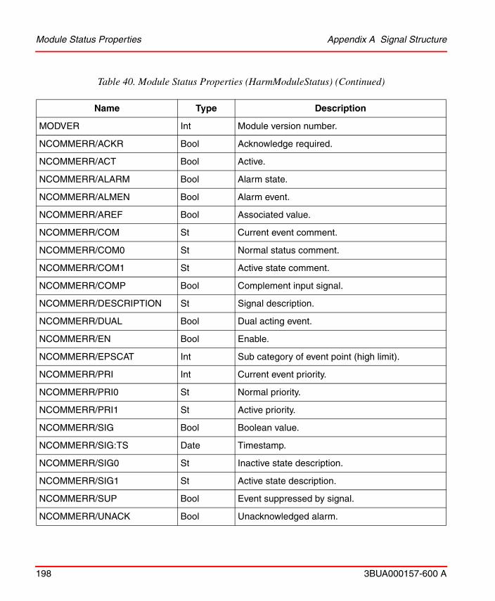
Module Status Properties Appendix A Signal Structure
198 3BUA000157-600 A
MODVER Int Module version number.
NCOMMERR/ACKR Bool Acknowledge required.
NCOMMERR/ACT Bool Active.
NCOMMERR/ALARM Bool Alarm state.
NCOMMERR/ALMEN Bool Alarm event.
NCOMMERR/AREF Bool Associated value.
NCOMMERR/COM St Current event comment.
NCOMMERR/COM0 St Normal status comment.
NCOMMERR/COM1 St Active state comment.
NCOMMERR/COMP Bool Complement input signal.
NCOMMERR/DESCRIPTION St Signal description.
NCOMMERR/DUAL Bool Dual acting event.
NCOMMERR/EN Bool Enable.
NCOMMERR/EPSCAT Int Sub category of event point (high limit).
NCOMMERR/PRI Int Current event priority.
NCOMMERR/PRI0 St Normal priority.
NCOMMERR/PRI1 St Active priority.
NCOMMERR/SIG Bool Boolean value.
NCOMMERR/SIG:TS Date Timestamp.
NCOMMERR/SIG0 St Inactive state description.
NCOMMERR/SIG1 St Active state description.
NCOMMERR/SUP Bool Event suppressed by signal.
NCOMMERR/UNACK Bool Unacknowledged alarm.
Table 40. Module Status Properties (HarmModuleStatus) (Continued)
Name Type Description

Appendix A Signal Structure Module Status Properties
3BUA000157-600 A 199
NCOMMERR/UNACKEP Bool Unacknowledged event point (status or alarm).
NMODERR/ACKR Bool Acknowledge required.
NMODERR/ACT Bool Active.
NMODERR/ALARM Bool Alarm state.
NMODERR/ALMEN Bool Alarm event.
NMODERR/AREF Bool Associated value.
NMODERR/COM St Current event comment.
NMODERR/COM0 St Normal status comment.
NMODERR/COM1 St Active state comment.
NMODERR/COMP Bool Complement input signal.
NMODERR/DESCRIPTION St Signal description.
NMODERR/DUAL Bool Dual acting event.
NMODERR/EN Bool Enable.
NMODERR/EPSCAT Int Sub category of event point (high limit).
NMODERR/PRI Int Current event priority.
NMODERR/PRI0 St Normal priority.
NMODERR/PRI1 St Active priority.
NMODERR/SIG Bool Boolean value.
NMODERR/SIG0 St Inactive state description.
NMODERR/SIG1 St Active state description.
NMODERR/SUP Bool Event suppressed by signal.
NMODERR/UNACK Bool Unacknowledged alarm.
NMODERR/UNACKEP Bool Unacknowledged event point (status or alarm).
Table 40. Module Status Properties (HarmModuleStatus) (Continued)
Name Type Description
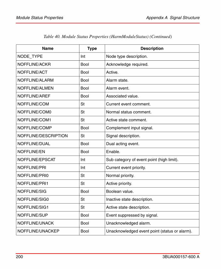
Module Status Properties Appendix A Signal Structure
200 3BUA000157-600 A
NODE_TYPE Int Node type description.
NOFFLINE/ACKR Bool Acknowledge required.
NOFFLINE/ACT Bool Active.
NOFFLINE/ALARM Bool Alarm state.
NOFFLINE/ALMEN Bool Alarm event.
NOFFLINE/AREF Bool Associated value.
NOFFLINE/COM St Current event comment.
NOFFLINE/COM0 St Normal status comment.
NOFFLINE/COM1 St Active state comment.
NOFFLINE/COMP Bool Complement input signal.
NOFFLINE/DESCRIPTION St Signal description.
NOFFLINE/DUAL Bool Dual acting event.
NOFFLINE/EN Bool Enable.
NOFFLINE/EPSCAT Int Sub category of event point (high limit).
NOFFLINE/PRI Int Current event priority.
NOFFLINE/PRI0 St Normal priority.
NOFFLINE/PRI1 St Active priority.
NOFFLINE/SIG Bool Boolean value.
NOFFLINE/SIG0 St Inactive state description.
NOFFLINE/SIG1 St Active state description.
NOFFLINE/SUP Bool Event suppressed by signal.
NOFFLINE/UNACK Bool Unacknowledged alarm.
NOFFLINE/UNACKEP Bool Unacknowledged event point (status or alarm).
Table 40. Module Status Properties (HarmModuleStatus) (Continued)
Name Type Description
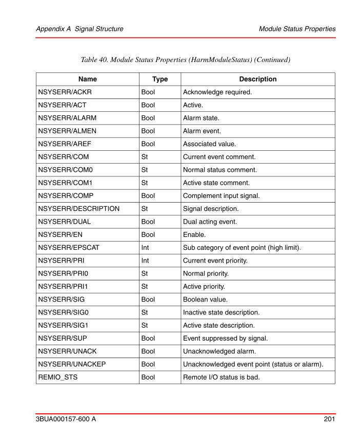
Appendix A Signal Structure Module Status Properties
3BUA000157-600 A 201
NSYSERR/ACKR Bool Acknowledge required.
NSYSERR/ACT Bool Active.
NSYSERR/ALARM Bool Alarm state.
NSYSERR/ALMEN Bool Alarm event.
NSYSERR/AREF Bool Associated value.
NSYSERR/COM St Current event comment.
NSYSERR/COM0 St Normal status comment.
NSYSERR/COM1 St Active state comment.
NSYSERR/COMP Bool Complement input signal.
NSYSERR/DESCRIPTION St Signal description.
NSYSERR/DUAL Bool Dual acting event.
NSYSERR/EN Bool Enable.
NSYSERR/EPSCAT Int Sub category of event point (high limit).
NSYSERR/PRI Int Current event priority.
NSYSERR/PRI0 St Normal priority.
NSYSERR/PRI1 St Active priority.
NSYSERR/SIG Bool Boolean value.
NSYSERR/SIG0 St Inactive state description.
NSYSERR/SIG1 St Active state description.
NSYSERR/SUP Bool Event suppressed by signal.
NSYSERR/UNACK Bool Unacknowledged alarm.
NSYSERR/UNACKEP Bool Unacknowledged event point (status or alarm).
REMIO_STS Bool Remote I/O status is bad.
Table 40. Module Status Properties (HarmModuleStatus) (Continued)
Name Type Description

Module Status Properties Appendix A Signal Structure
202 3BUA000157-600 A
SECONDARY Bool Module is secondary of a redundant pair.
SPECSRCVD Bool Blockware specifications received.
SPECTIMESTAMP St Time of last spec exception from blockware.
STATECHANGE/ACKR Bool Acknowledge required.
STATECHANGE/ACT Bool Active.
STATECHANGE/ALARM Bool Alarm state.
STATECHANGE/ALMEN Bool Alarm event.
STATECHANGE/AREF Bool Associated value.
STATECHANGE/COM St Current event comment.
STATECHANGE/COM0 St Normal status comment.
STATECHANGE/COM1 St Active state comment.
STATECHANGE/COMP Bool Complement input signal.
STATECHANGE/DESCRIPTION St Signal description.
STATECHANGE/DUAL Bool Dual acting event.
STATECHANGE/EN Bool Enable.
STATECHANGE/EPSCAT Int Sub category of event point (high limit).
STATECHANGE/PRI Int Current event priority.
STATECHANGE/PRI0 St Normal priority.
STATECHANGE/PRI1 St Active priority.
STATECHANGE/SIG Bool Boolean value.
STATECHANGE/SIG0 St Inactive state description.
STATECHANGE/SIG1 St Active state description.
STATECHANGE/SUP Bool Event suppressed by signal.
Table 40. Module Status Properties (HarmModuleStatus) (Continued)
Name Type Description

Appendix A Signal Structure PhaseX Properties
3BUA000157-600 A 203
PhaseX PropertiesThe PhaseX tag contains all the properties listed in Table 41 and Table 41.
STATECHANGE/UNACK Bool Unacknowledged alarm.
STATECHANGE/UNACKEP Bool Unacknowledged event point (status or alarm).
XMIT_ACK Bool Global acknowledgements should be sent.
XMIT_SILENCE Bool Global alarm silence should be sent.
Table 41. PhaseX Properties (HarmPhaseX)
Name Type Description
ACQ Bool Acquired status.
ALMACKBC Bool Broadcast alarm acknowledge events.
BATCH St Batch ID.
BATCH1 St —
BATCHMGR St —
CAMPAIGN St Campaign ID.
COMMAND Int Batch command.
DBGSTOP Bool Batch program is stopped by debugger.
DEBUG Real Debug.
FASTCNTR Int Fast event counter.
FASTTM Real Fast reporting maxtime.
FLTCODE Int Fault code.
FLTCODE:S St Fault code string.
Table 40. Module Status Properties (HarmModuleStatus) (Continued)
Name Type Description
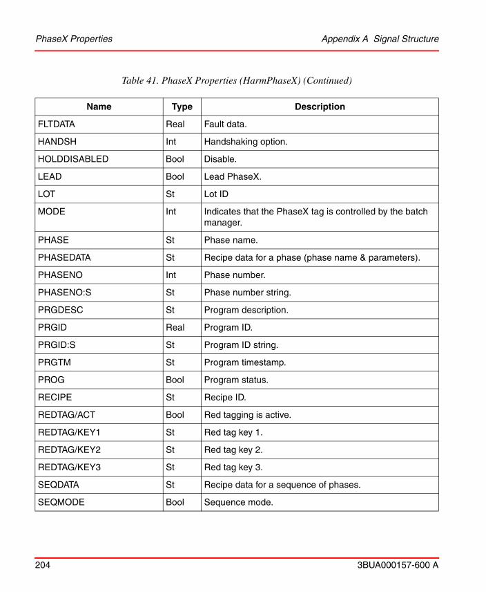
PhaseX Properties Appendix A Signal Structure
204 3BUA000157-600 A
FLTDATA Real Fault data.
HANDSH Int Handshaking option.
HOLDDISABLED Bool Disable.
LEAD Bool Lead PhaseX.
LOT St Lot ID
MODE Int Indicates that the PhaseX tag is controlled by the batch manager.
PHASE St Phase name.
PHASEDATA St Recipe data for a phase (phase name & parameters).
PHASENO Int Phase number.
PHASENO:S St Phase number string.
PRGDESC St Program description.
PRGID Real Program ID.
PRGID:S St Program ID string.
PRGTM St Program timestamp.
PROG Bool Program status.
RECIPE St Recipe ID.
REDTAG/ACT Bool Red tagging is active.
REDTAG/KEY1 St Red tag key 1.
REDTAG/KEY2 St Red tag key 2.
REDTAG/KEY3 St Red tag key 3.
SEQDATA St Recipe data for a sequence of phases.
SEQMODE Bool Sequence mode.
Table 41. PhaseX Properties (HarmPhaseX) (Continued)
Name Type Description

Appendix A Signal Structure PhaseX Properties
3BUA000157-600 A 205
SLOWCNTR Int Slow event counter.
SLOWCNTRXRP Int Slow event counter XRP.
SLOWTM Real Slow reporting maxtime.
STATE Int State.
STATE:S St State string.
STOPDISABLED Bool Disable.
SYSFAULT/ACKR Bool Acknowledge required.
SYSFAULT/ACT Bool Active.
SYSFAULT/ALARM Bool Alarm state.
SYSFAULT/ALMEN Bool Alarm event.
SYSFAULT/AREF Bool Associated value
SYSFAULT/COM St Current event comment.
SYSFAULT/COM0 St Normal status comment.
SYSFAULT/COM1 St Active state comment.
SYSFAULT/COMP Bool Complement input signal.
SYSFAULT/DESCRIPTION St Signal description.
SYSFAULT/DUAL Bool Dual acting event.
SYSFAULT/EN Bool Enable.
SYSFAULT/EPSCAT Int Sub category of event point (high limit).
SYSFAULT/PRI Int Current event priority.
SYSFAULT/PRI0 Int Normal priority.
SYSFAULT/PRI1 St Active priority.
SYSFAULT/SIG Bool Boolean value.
Table 41. PhaseX Properties (HarmPhaseX) (Continued)
Name Type Description

PhaseX Properties Appendix A Signal Structure
206 3BUA000157-600 A
SYSFAULT/SIG0 St Inactive state description.
SYSFAULT/SIG1 St Active state description.
SYSFAULT/SUP Bool Event suppressed by signal.
SYSFAULT/UNACK Bool Unacknowledged alarm.
SYSFAULT/UNACKEP Bool Unacknowledged event point (status or alarm).
USERFAULT/ACKR Bool Acknowledge required.
USERFAULT/ACT Bool Active.
USERFAULT/ALARM Bool Alarm state.
USERFAULT/ALMEN Bool Alarm event.
USERFAULT/AREF Bool Associated value.
USERFAULT/COM St Current event comment.
USERFAULT/COM0 St Normal status comment.
USERFAULT/COM1 St Active state comment.
USERFAULT/COMP Bool Complement input signal.
USERFAULT/DESCRIPTION St Signal description.
USERFAULT/DUAL Bool Dual acting event.
USERFAULT/EN Bool Enable.
USERFAULT/EPSCAT Int Sub category of event point (high limit).
USERFAULT/PRI Int Current event priority.
USERFAULT/PRI0 St Normal priority.
USERFAULT/PRI1 St Active priority.
USERFAULT/SIG Bool Boolean value.
USERFAULT/SIG0 St Inactive state description.
Table 41. PhaseX Properties (HarmPhaseX) (Continued)
Name Type Description

Appendix A Signal Structure PhaseX Properties
3BUA000157-600 A 207
USERFAULT/SIG1 St Active state description.
USERFAULT/SUP Bool Event suppressed by signal.
USERFAULT/UNACK Bool Unacknowledged alarm.
USERFAULT/UNACKEP Bool Unacknowledged event point (status or alarm).
USERMSG/ACKR Bool Acknowledge required.
USERMSG/ACT Bool Active.
USERMSG/ALARM Bool Alarm state.
USERMSG/ALMEN Bool Alarm event.
USERMSG/AREF Bool Associated value.
USERMSG/COM St Current event comment.
USERMSG/COM0 St Normal status comment.
USERMSG/COM1 St Active state comment.
USERMSG/COMP Bool Complement input signal.
USERMSG/DESCRIPTION St Signal description.
USERMSG/DUAL Bool Dual acting event.
USERMSG/EN Bool Enable.
USERMSG/EPSCAT Int Sub category of event point (high limit).
USERMSG/PRI Int Current event priority.
USERMSG/PRI0 St Normal priority.
USERMSG/PRI1 St Active priority.
USERMSG/SIG Bool Boolean value.
USERMSG/SIG0 St Inactive state description.
USERMSG/SIG1 St Active state description.
Table 41. PhaseX Properties (HarmPhaseX) (Continued)
Name Type Description
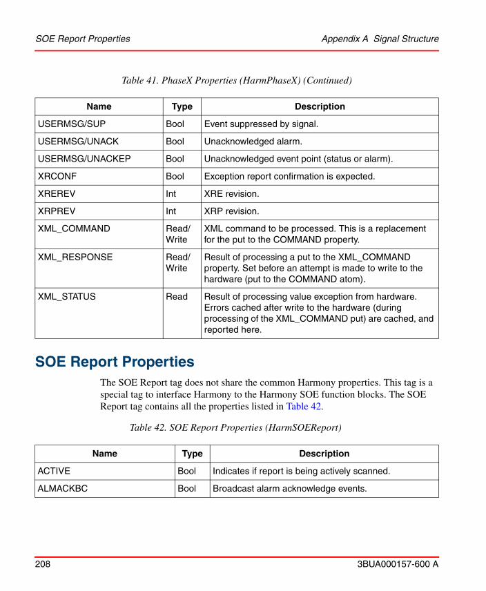
SOE Report Properties Appendix A Signal Structure
208 3BUA000157-600 A
SOE Report Properties
The SOE Report tag does not share the common Harmony properties. This tag is a special tag to interface Harmony to the Harmony SOE function blocks. The SOE Report tag contains all the properties listed in Table 42.
USERMSG/SUP Bool Event suppressed by signal.
USERMSG/UNACK Bool Unacknowledged alarm.
USERMSG/UNACKEP Bool Unacknowledged event point (status or alarm).
XRCONF Bool Exception report confirmation is expected.
XREREV Int XRE revision.
XRPREV Int XRP revision.
XML_COMMAND Read/Write
XML command to be processed. This is a replacement for the put to the COMMAND property.
XML_RESPONSE Read/Write
Result of processing a put to the XML_COMMAND property. Set before an attempt is made to write to the hardware (put to the COMMAND atom).
XML_STATUS Read Result of processing value exception from hardware. Errors cached after write to the hardware (during processing of the XML_COMMAND put) are cached, and reported here.
Table 42. SOE Report Properties (HarmSOEReport)
Name Type Description
ACTIVE Bool Indicates if report is being actively scanned.
ALMACKBC Bool Broadcast alarm acknowledge events.
Table 41. PhaseX Properties (HarmPhaseX) (Continued)
Name Type Description

Appendix A Signal Structure SOE Report Properties
3BUA000157-600 A 209
CACHETIME Real Time to wait, in seconds, before clearing unread SOEDATA.
FB1/COMP Bool Complement input signal.
FB1/DESCRIPTION St Signal description.
FB1/SIG Bool Boolean value.
FB1/SIG0 St Inactive state description.
FB1/SIG1 St Active state description.
OUT/ACKR Bool Acknowledge required.
OUT/ACT Bool Active.
OUT/ALARM Bool Alarm state.
OUT/ALMEN Bool Alarm event.
OUT/AREF Bool Associated value.
OUT/COM St Current event comment.
OUT/COM0 St Normal status comment.
OUT/COM1 St Active state comment.
OUT/COMP Bool Complement input signal.
OUT/DESCRIPTION St Signal description.
OUT/DUAL Bool Dual acting event.
OUT/EN Bool Enable.
OUT/EPSCAT Int Sub category of event point (high limit).
OUT/PRI Int Current event priority.
OUT/PRI0 St Normal priority.
OUT/PRI1 St Active priority.
Table 42. SOE Report Properties (HarmSOEReport) (Continued)
Name Type Description

SOE Report Properties Appendix A Signal Structure
210 3BUA000157-600 A
OUT/SIG Bool Boolean value.
OUT/SIG0 St Inactive state description.
OUT/SIG1 St Active state description.
OUT/SUP Bool Event suppressed by signal.
OUT/UNACK Bool Unacknowledged alarm.
OUT/UNACKEP Bool Unacknowledged event point (status or alarm).
OUTOVR Bool State is overridden.
RECORDER St Reference to SOE recorder.
RECORDERID St Reference to SOE recorder (UUID).
REDTAG/ACT Bool Red tagging is active.
REDTAG/KEY1 St Red tag key 1.
REDTAG/KEY2 St Red tag key 2.
REDTAG/KEY3 St Red tag key 3.
REPORTREAD Bool Indicates if SOE Report is being read.
REPORTTYPE Int Type of SOE Report to generate.
REPORTTYPE:S St Type of SOE Report to generate string.
RESCMD Bool Reset command received.
RESIN Bool Logic reset input received.
SETCMD Bool Set command received.
SETIN Bool Logic set input received.
SETPER Bool Set permissive.
SOEDATA St SOE event data in XML format.
STATECHANGE/ACKR Bool Acknowledge required.
Table 42. SOE Report Properties (HarmSOEReport) (Continued)
Name Type Description
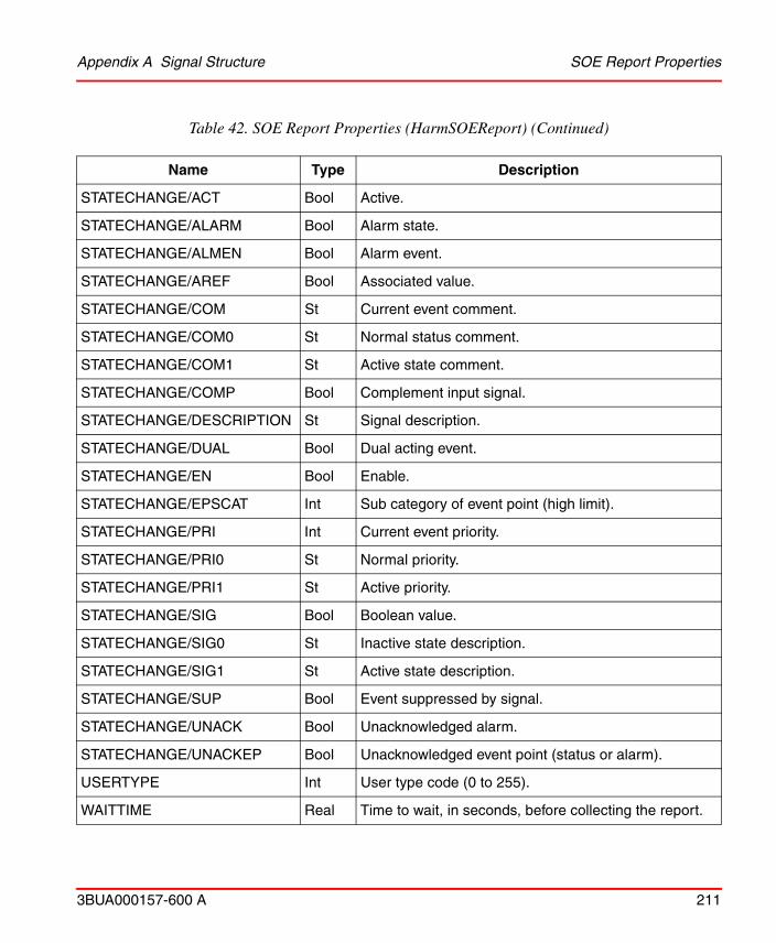
Appendix A Signal Structure SOE Report Properties
3BUA000157-600 A 211
STATECHANGE/ACT Bool Active.
STATECHANGE/ALARM Bool Alarm state.
STATECHANGE/ALMEN Bool Alarm event.
STATECHANGE/AREF Bool Associated value.
STATECHANGE/COM St Current event comment.
STATECHANGE/COM0 St Normal status comment.
STATECHANGE/COM1 St Active state comment.
STATECHANGE/COMP Bool Complement input signal.
STATECHANGE/DESCRIPTION St Signal description.
STATECHANGE/DUAL Bool Dual acting event.
STATECHANGE/EN Bool Enable.
STATECHANGE/EPSCAT Int Sub category of event point (high limit).
STATECHANGE/PRI Int Current event priority.
STATECHANGE/PRI0 St Normal priority.
STATECHANGE/PRI1 St Active priority.
STATECHANGE/SIG Bool Boolean value.
STATECHANGE/SIG0 St Inactive state description.
STATECHANGE/SIG1 St Active state description.
STATECHANGE/SUP Bool Event suppressed by signal.
STATECHANGE/UNACK Bool Unacknowledged alarm.
STATECHANGE/UNACKEP Bool Unacknowledged event point (status or alarm).
USERTYPE Int User type code (0 to 255).
WAITTIME Real Time to wait, in seconds, before collecting the report.
Table 42. SOE Report Properties (HarmSOEReport) (Continued)
Name Type Description
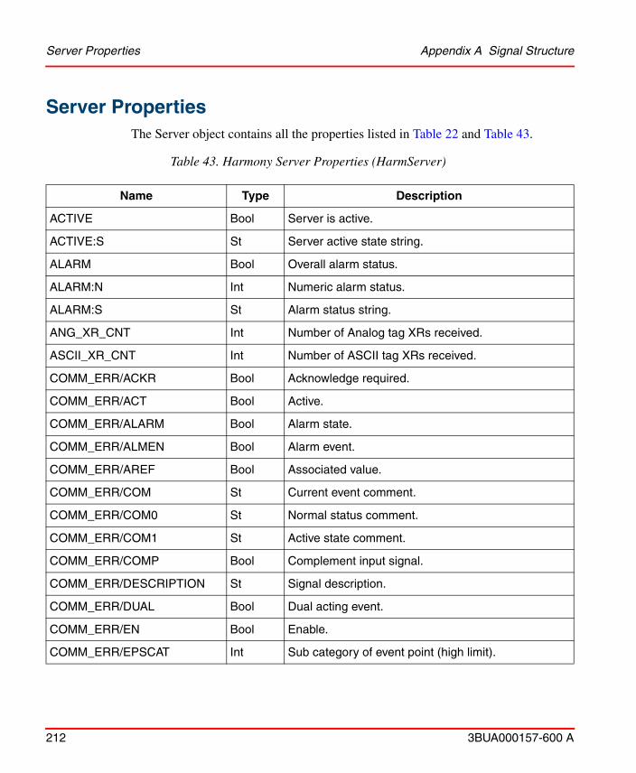
Server Properties Appendix A Signal Structure
212 3BUA000157-600 A
Server PropertiesThe Server object contains all the properties listed in Table 22 and Table 43.
Table 43. Harmony Server Properties (HarmServer)
Name Type Description
ACTIVE Bool Server is active.
ACTIVE:S St Server active state string.
ALARM Bool Overall alarm status.
ALARM:N Int Numeric alarm status.
ALARM:S St Alarm status string.
ANG_XR_CNT Int Number of Analog tag XRs received.
ASCII_XR_CNT Int Number of ASCII tag XRs received.
COMM_ERR/ACKR Bool Acknowledge required.
COMM_ERR/ACT Bool Active.
COMM_ERR/ALARM Bool Alarm state.
COMM_ERR/ALMEN Bool Alarm event.
COMM_ERR/AREF Bool Associated value.
COMM_ERR/COM St Current event comment.
COMM_ERR/COM0 St Normal status comment.
COMM_ERR/COM1 St Active state comment.
COMM_ERR/COMP Bool Complement input signal.
COMM_ERR/DESCRIPTION St Signal description.
COMM_ERR/DUAL Bool Dual acting event.
COMM_ERR/EN Bool Enable.
COMM_ERR/EPSCAT Int Sub category of event point (high limit).

Appendix A Signal Structure Server Properties
3BUA000157-600 A 213
COMM_ERR/PRI Int Current event priority.
COMM_ERR/PRI0 St Normal priority.
COMM_ERR/PRI1 St Active priority.
COMM_ERR/SIG Bool Boolean value.
COMM_ERR/SIG0 St Inactive state description.
COMM_ERR/SIG1 St Active state description.
COMM_ERR/SUP Bool Event suppressed by signal.
COMM_ERR/UNACK Bool Unacknowledged alarm.
COMM_ERR/UNACKEP Bool Unacknowledged event point (status or alarm).
DAANG_XR_CNT Int Number of DAANG tag XRs received.
DADIG_XR_CNT Int Number of DADIG tag XRs received.
DD_XR_CNT Int Number of DD tag XRs received.
DIG_XR_CNT Int Number of Digital tag XRs received.
DOMAIN St Servers domain.
EAIN_XR_CNT Int Number of Enhanced Analog input XRs received.
EAOUT_XR_CNT Int Number of Enhanced Analog output XRs received.
EDIN_XR_CNT Int Number of Enhanced Digital input XRs received.
EDOUT_XR_CNT Int Number of Enhanced Digital output XRs received.
ENHPUTEVENT Bool Enable enhanced tuning message.
FILTERBQ Bool Filter bad quality alarms caused by hardware failure.
FILTERXR Bool Change XR filtering on ICI restart.
GROUPID St Redundant Server group ID.
HARM_NS_ENBL Bool Enable Harmony namespace support.
Table 43. Harmony Server Properties (HarmServer) (Continued)
Name Type Description
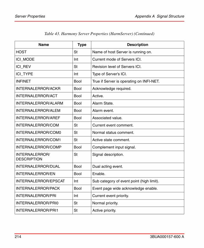
Server Properties Appendix A Signal Structure
214 3BUA000157-600 A
HOST St Name of host Server is running on.
ICI_MODE Int Current mode of Servers ICI.
ICI_REV St Revision level of Servers ICI.
ICI_TYPE Int Type of Server’s ICI.
INFINET Bool True if Server is operating on INFI-NET.
INTERNALERROR/ACKR Bool Acknowledge required.
INTERNALERROR/ACT Bool Active.
INTERNALERROR/ALARM Bool Alarm State.
INTERNALERROR/ALEM Bool Alarm event.
INTERNALERROR/AREF Bool Associated value.
INTERNALERROR/COM St Current event comment.
INTERNALERROR/COM0 St Normal status comment.
INTERNALERROR/COM1 St Active state comment.
INTERNALERROR/COMP Bool Complement input signal.
INTERNALERROR/ DESCRIPTION
St Signal description.
INTERNALERROR/DUAL Bool Dual acting event.
INTERNALERROR/EN Bool Enable.
INTERNALERROR/EPSCAT Int Sub category of event point (high limit).
INTERNALERROR/PACK Bool Event page wide acknowledge enable.
INTERNALERROR/PRI Int Current event priority.
INTERNALERROR/PRI0 St Normal priority.
INTERNALERROR/PRI1 St Active priority.
Table 43. Harmony Server Properties (HarmServer) (Continued)
Name Type Description

Appendix A Signal Structure Server Properties
3BUA000157-600 A 215
INTERNALERROR/SIG Bool Boolean value.
INTERNALERROR/SIG0 St Inactive state description.
INTERNALERROR/SIG1 St Active state description.
INTERNALERROR/SUP Bool Event suppressed by signal.
INTERNALERROR/UNACK Bool Unacknowledged alarm.
INTERNALERROR/UNACKEP Bool Unacknowledged event point (status or alarm).
LOOP_TIME St Current INFI-NET loop time.
MAX_TAGS Int Maximum number of tags Server licensed to load.
MOD_TSTAMP Bool True if module timestamping is enabled.
MSDD_XR_CNT Int Number of MSDD tag XRs received.
MSTAT_XR_CNT Int Number of Module Status tag XRs received.
NO_BULK_EXPORT_PERSIST Bool Disable persistence for export tags on bulk update.
OISMODE Bool Run RTDS in OIS mode (Add 60 day offset for OIS consoles).
PERCSYNC Real Synchronization progress (Percent).
RCM_XR_CNT Int Number of RCM tag XRs received.
RCVGBLACK Bool Monitor global acknowledge messages from the loop.
RCVGBLSIL Bool Monitor global silence messages from the loop.
REDID St ID of redundant Server.
REDSTATE/ACKR Bool Acknowledge required.
REDSTATE/ACT Bool Active.
REDSTATE/ALARM Bool Alarm state.
REDSTATE/ALMEN Bool Alarm event.
Table 43. Harmony Server Properties (HarmServer) (Continued)
Name Type Description

Server Properties Appendix A Signal Structure
216 3BUA000157-600 A
REDSTATE/AREF Bool Associated value.
REDSTATE/COM St Current event comment.
REDSTATE/COM0 St Normal status comment.
REDSTATE/COM1 St Active state comment.
REDSTATE/COMP Bool Complement input signal.
REDSTATE/DESCRIPTION St Signal description.
REDSTATE/DUAL Bool Dual acting event.
REDSTATE/EN Bool Enable.
REDSTATE/EPSCAT Int Sub category of event point (high limit).
REDSTATE/PRI Int Current event priority.
REDSTATE/PRI0 St Normal priority.
REDSTATE/PRI1 St Active priority.
REDSTATE/SIG Bool Boolean value.
REDSTATE/SIG0 St Inactive state description.
REDSTATE/SIG1 St Active state description.
REDSTATE/SUP Bool Event suppressed by signal.
REDSTATE/UNACK Bool Unacknowledged alarm.
REDSTATE/UNACKEP Bool Unacknowledged event point (status or alarm).
RESTARTS Int Number of ICI restarts.
RMCB_XR_CNT Int Number of RMCB tag XRs received.
RMSC_XR_CNT Int Number of RMSC tag XRs received.
SEM_AUTO_ADJTIME Bool Enable SEM wallclock daylight savings time adjustment.
Table 43. Harmony Server Properties (HarmServer) (Continued)
Name Type Description
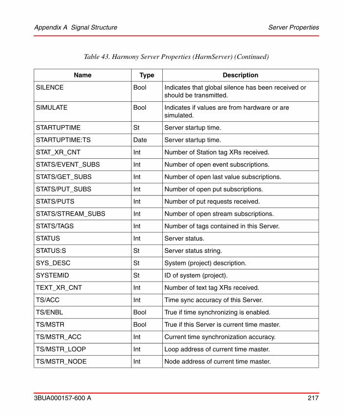
Appendix A Signal Structure Server Properties
3BUA000157-600 A 217
SILENCE Bool Indicates that global silence has been received or should be transmitted.
SIMULATE Bool Indicates if values are from hardware or are simulated.
STARTUPTIME St Server startup time.
STARTUPTIME:TS Date Server startup time.
STAT_XR_CNT Int Number of Station tag XRs received.
STATS/EVENT_SUBS Int Number of open event subscriptions.
STATS/GET_SUBS Int Number of open last value subscriptions.
STATS/PUT_SUBS Int Number of open put subscriptions.
STATS/PUTS Int Number of put requests received.
STATS/STREAM_SUBS Int Number of open stream subscriptions.
STATS/TAGS Int Number of tags contained in this Server.
STATUS Int Server status.
STATUS:S St Server status string.
SYS_DESC St System (project) description.
SYSTEMID St ID of system (project).
TEXT_XR_CNT Int Number of text tag XRs received.
TS/ACC Int Time sync accuracy of this Server.
TS/ENBL Bool True if time synchronizing is enabled.
TS/MSTR Bool True if this Server is current time master.
TS/MSTR_ACC Int Current time synchronization accuracy.
TS/MSTR_LOOP Int Loop address of current time master.
TS/MSTR_NODE Int Node address of current time master.
Table 43. Harmony Server Properties (HarmServer) (Continued)
Name Type Description
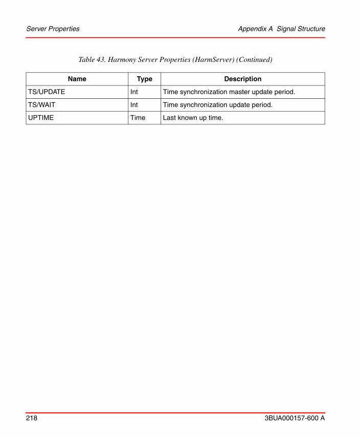
Server Properties Appendix A Signal Structure
218 3BUA000157-600 A
TS/UPDATE Int Time synchronization master update period.
TS/WAIT Int Time synchronization update period.
UPTIME Time Last known up time.
Table 43. Harmony Server Properties (HarmServer) (Continued)
Name Type Description
3BUA000157-600 A 219
Appendix B Quality Definition
IntroductionThe purpose of this appendix is to describe the tag.property qualities in Harmony.
DescriptionEvery property consists of following three pieces of information: a value, a quality, and a timestamp. The quality describes the state of the property that originates anywhere in the process control system.
An application in the process control system (function block in a controller or in Harmony) can evaluate the provided quality information and can apply rules for further processing (use of values with a determined quality, displaying of values with quality, use the quality for filter purposes).
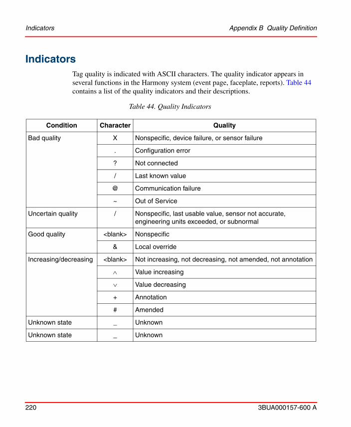
Indicators Appendix B Quality Definition
220 3BUA000157-600 A
IndicatorsTag quality is indicated with ASCII characters. The quality indicator appears in several functions in the Harmony system (event page, faceplate, reports). Table 44 contains a list of the quality indicators and their descriptions.
Table 44. Quality Indicators
Condition Character Quality
Bad quality X Nonspecific, device failure, or sensor failure
. Configuration error
? Not connected
/ Last known value
@ Communication failure
~ Out of Service
Uncertain quality / Nonspecific, last usable value, sensor not accurate, engineering units exceeded, or subnormal
Good quality <blank> Nonspecific
& Local override
Increasing/decreasing <blank> Not increasing, not decreasing, not amended, not annotation
Value increasing
Value decreasing
+ Annotation
# Amended
Unknown state _ Unknown
Unknown state _ Unknown

Appendix B Quality Definition OPC Quality Definition
3BUA000157-600 A 221
OPC Quality DefinitionThe quality definition is based on the quality defined by OPC. The OPC standard defines property quality as a 16 bit data item. The lower eight bits of quality flags are defined as a combination of three enumerated values: quality status (two bits), substatus (four bits), and limit status (two bits). The higher eight bits are available for vendor specific use (vendor specific status). The OPC quality structure is shown in Table 45.
L = limit status.S = substatus.Q = quality status.VS = vendor specific status.
OPC subdivides the quality into the three categories of good, uncertain, and bad. Each category is further subdivided into up to 16 substatuses. The current definition of the OPC quality is described in OPC Quality Flags on page 226.
Table 45. OPC Quality Structure
Bit 15 14 13 12 11 10 09 08 07 06 05 04 03 02 01 00
Use VS VS VS VS VS VS VS VS Q Q S S S S L L
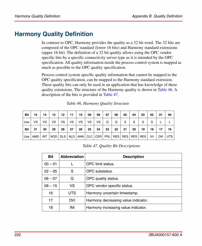
Harmony Quality Definition Appendix B Quality Definition
222 3BUA000157-600 A
Harmony Quality DefinitionIn contrast to OPC, Harmony provides the quality as a 32 bit word. The 32 bits are composed of the OPC standard (lower 16 bits) and Harmony standard extensions (upper 16 bit). The definition of a 32 bit quality allows using the OPC vendor specific bits by a specific connectivity server type as it is intended by the OPC specification. All quality information inside the process control system is mapped as much as possible to the OPC quality specification.
Process control system specific quality information that cannot be mapped to the OPC quality specification, can be mapped to the Harmony standard extension. These quality bits can only be used in an application that has knowledge of these quality extensions. The structure of the Harmony quality is shown in Table 46. A description of the bits is provided in Table 47.
Table 46. Harmony Quality Structure
Bit 15 14 13 12 11 10 09 08 07 06 05 04 03 02 01 00
Use VS VS VS VS VS VS VS VS Q Q S S S S L L
Bit 31 30 29 28 27 26 25 24 23 22 21 20 19 18 17 16
Use AMD INT NOD DLS NLD ANN CLC CER PRJ RES RES RES RES IVI DVI UTS
Table 47. Quality Bit Descriptions
Bit Abbreviation Description
00 – 01 L OPC limit status.
02 – 05 S OPC substatus.
06 – 07 Q OPC quality status.
08 – 15 VS OPC vendor specific status.
16 UTS Harmony uncertain timestamp.
17 DVI Harmony decreasing value indicator.
18 INI Harmony increasing value indicator.
Appendix B Quality Definition Tag.Property Quality for Process Properties
3BUA000157-600 A 223
In addition to the OPC quality specification (quality for process properties), Harmony also provides quality on a tag basis. This quality is derived from the quality of the properties. The quality on property and tag basis, have the same structure.
Tag.Property Quality for Process PropertiesProcess properties change their value, quality, and timestamp dependent on process state. The current process properties consist of value, quality, and timestamp. Quality and timestamp represent the last change of the associated value.
Tag.Property Quality for Computed PropertiesComputed properties usually inherit the timestamp from the most recently changed source of the computation. The quality of these properties is usually inherited from the source as well. A common rule is that all needed properties will influence the resulting quality.
An OR needs only one input to be true. If that input has a good quality the result will have a good quality as well. In case of an AND, all inputs need to have a good quality. That means the worst quality will rule the resulting quality. If the result encounters a scaling or conversion error, a CER error can be reported. The result should also have the calculated bit set. This allows an application to discern that the result is from a calculation.
19 – 22 RES Harmony reserved.
23 PRJ Projected value (historian only).
24 CER Scaling/conversion error.
25 CLC Calculated result.
Table 47. Quality Bit Descriptions (Continued)
Bit Abbreviation Description
Tag.Property Quality for Configuration Data Appendix B Quality Definition
224 3BUA000157-600 A
Tag.Property Quality for Configuration DataAll configuration data are part of basic components (SymObject, PSigReal). The quality of these values is always GOOD non_specifc. The associated timestamp is the time of the configuration (property CHTIME). The only exception is when the configuration data is corrupt or not accessible.
Tag.Property Quality for Event Point Related PropertiesMost of the event point related properties contain configuration data (refer to Tag.Property Quality for Configuration Data on page 224). The computed properties have a direct relationship to the generated event. These are the properties ACT (event point active) and UNACKEP (event point not acknowledged).
Every event is generated from an property with quality and timestamp. The computed event point related properties get the quality of the associated process property. The timestamp has a direct relationship to the associated event.
Tag QualityOPC defines a quality specified on property basis. In addition, Harmony also provides a quality on tag basis. The tag class (SymTag) provides separate properties for the tag related quality. These properties are derived from other properties.
Properties
Quality
This property is part of the SymTag class. It represents the overall quality of the tag. It provides this quality in the same format defined previously for tag property quality. Specifically the value component of this property returns numerically the Harmony quality word and textually the three character quality string. The quality component of this property always returns the quality status GOOD non_specific as it represents the quality of this property, not the tag. The timestamp represents the last change in the value of this property.
Appendix B Quality Definition Harmony Quality Information
3BUA000157-600 A 225
Bad
This property is part of the SymTag class. It represents the overall BAD quality of the tag. It provides this quality as a Boolean status signal with an associated event point. The quality component of this property always returns the quality status GOOD non_specific as it represents the quality of this property, not the tag. The timestamp represents the last change in the value of this property.
Suspended
This property is a part of the HarmonyTag class (used for the Harmony functionality substitution and off scan). It provides this quality as a Boolean status signal. The quality component of this property always returns the quality status GOOD non_specific as it represents the quality of this property, not the tag. The timestamp represents the last change in the value of this property.
Harmony Quality Information
The connectivity server provides the quality information shown in Table 48. Table 49 describes the mapping rules.
Table 48. Harmony Quality Information
Quality Description Cause
No connection to gateway(control system).
The gateway or all connections to the gateway are not available.
Communication error, component failure.
Connection for the requested tag/tag.property not available.
For the requested property not connection handle available (no actualization).
Configuration of CCO and connectivity server do not match.
Requested property not available.
Requested property not available in the connectivity server.
Application requested for a Property not defined in the class definition.
Configuration change. Tag affected by configuration change.
Not applicable.
OPC Quality Flags Appendix B Quality Definition
226 3BUA000157-600 A
OPC Quality FlagsThe low eight bits of the quality flags are currently defined in the form of three bit fields: quality, substatus, and limit status. The eight quality bits are arranged as follows: QQSSSSLL
Decreasing value indicator.
Comparing old received value with current received value.
TRUE: value decreasing to the last received value.FALSE: old value less than or equal to new value.
Increasing value indicator. Comparing old received value with current received value.
TRUE: value increasing to the last received value.FALSE: old value greater than or equal to new value.
Table 49. Quality Mapping Rules
Connectivity Server Quality OPC Quality OPC Substatus
Connection gateway BAD Comm_Failure
Connection tag BAD Not_Connected
Not permitted request BAD Configuration_Error
Configuration not found BAD Configuration_Error
Connectivity server quality Harmony quality status
Value decreasing DVI Decreasing value indicator
Value increasing IVI Increasing value indicator
Table 48. Harmony Quality Information (Continued)
Quality Description Cause
Appendix B Quality Definition Quality Bits
3BUA000157-600 A 227
Quality Bits
Table 50 describes the values for the quality bits.
Substatus Bits
The layout of these bits depends on the value of the quality bits. The substatus bits for bad quality are shown in Table 51. Table 52 shows the substatus bits for uncertain quality. Table 53 shows the substatus bits for good quality.
Table 50. OPC Quality Bits
QQ Bit Value Define Description
0 00SSSSLL Bad Value is not useful for reasons indicated by the substatus.
1 01SSSSLL Uncertain Quality of the value is uncertain for reasons indicated by the substatus.
2 10SSSSLL N/A Not used by OPC.
3 11SSSSLL Good Quality of the value is good.
Table 51. Bad Quality Substatus
SSSS Bit Value Define Description
0 000000LL Non specific Value is bad but no specific reason is known.
1 000001LL Configuration error
Some Server specific problem with the configuration. For example the item is question has been deleted from the configuration.
2 000010LL Not connected Input is required to be logically connected to something but is not. This quality may reflect that no value is available at this time, for reasons like the value may have not been provided by the data source.
3 000011LL Device failure A device failure has been detected.
4 000100LL Sensor failure A sensor failure had been detected (the limit bits can provide additional diagnostic information in some situations.)
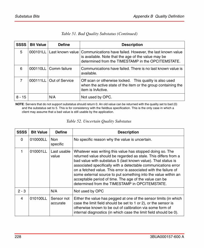
Substatus Bits Appendix B Quality Definition
228 3BUA000157-600 A
5 000101LL Last known value Communications have failed. However, the last known value is available. Note that the age of the value may be determined from the TIMESTAMP in the OPCITEMSTATE.
6 000110LL Comm failure Communications have failed. There is no last known value is available.
7 000111LL Out of Service Off scan or otherwise locked. This quality is also used when the active state of the item or the group containing the item is InActive.
8 - 15 N/A Not used by OPC.
NOTE: Servers that do not support substatus should return 0. An old value can be returned with the quality set to bad (0) and the substatus set to 5. This is for consistency with the fieldbus specification. This is the only case in which a client may assume that a bad value is still usable by the application.
Table 52. Uncertain Quality Substatus
SSSS Bit Value Define Description
0 010000LL Non specific
No specific reason why the value is uncertain.
1 010001LL Last usable value
Whatever was writing this value has stopped doing so. The returned value should be regarded as stale. This differs from a bad value with substatus 5 (last known value). That status is associated specifically with a detectable communications error on a fetched value. This error is associated with the failure of some external source to put something into the value within an acceptable period of time. The age of the value can be determined from the TIMESTAMP in OPCITEMSTATE.
2 - 3 N/A Not used by OPC
4 010100LL Sensor not accurate
Either the value has pegged at one of the sensor limits (in which case the limit field should be set to 1 or 2), or the sensor is otherwise known to be out of calibration via some form of internal diagnostics (in which case the limit field should be 0).
Table 51. Bad Quality Substatus (Continued)
SSSS Bit Value Define Description
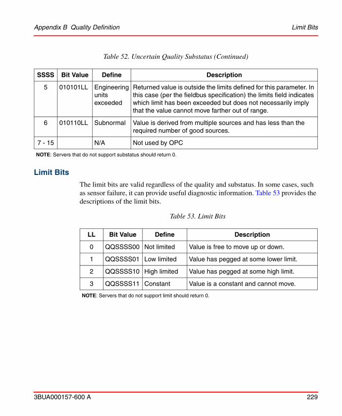
Appendix B Quality Definition Limit Bits
3BUA000157-600 A 229
Limit Bits
The limit bits are valid regardless of the quality and substatus. In some cases, such as sensor failure, it can provide useful diagnostic information. Table 53 provides the descriptions of the limit bits.
5 010101LL Engineering units exceeded
Returned value is outside the limits defined for this parameter. In this case (per the fieldbus specification) the limits field indicates which limit has been exceeded but does not necessarily imply that the value cannot move farther out of range.
6 010110LL Subnormal Value is derived from multiple sources and has less than the required number of good sources.
7 - 15 N/A Not used by OPC
NOTE: Servers that do not support substatus should return 0.
Table 53. Limit Bits
LL Bit Value Define Description
0 QQSSSS00 Not limited Value is free to move up or down.
1 QQSSSS01 Low limited Value has pegged at some lower limit.
2 QQSSSS10 High limited Value has pegged at some high limit.
3 QQSSSS11 Constant Value is a constant and cannot move.
NOTE: Servers that do not support limit should return 0.
Table 52. Uncertain Quality Substatus (Continued)
SSSS Bit Value Define Description
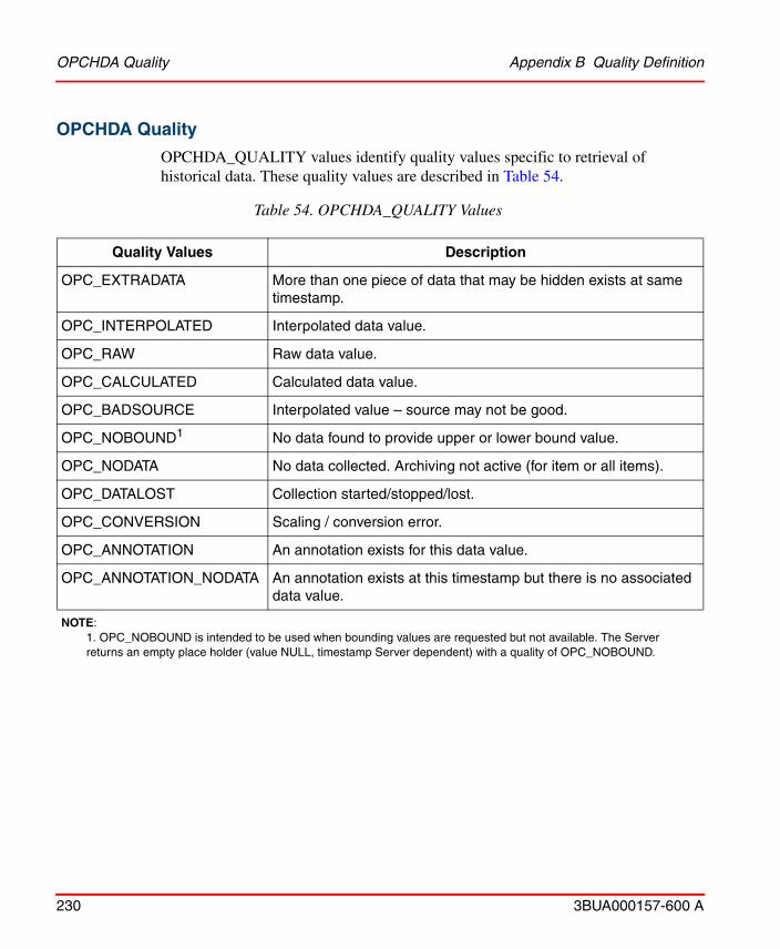
OPCHDA Quality Appendix B Quality Definition
230 3BUA000157-600 A
OPCHDA Quality
OPCHDA_QUALITY values identify quality values specific to retrieval of historical data. These quality values are described in Table 54.
Table 54. OPCHDA_QUALITY Values
Quality Values Description
OPC_EXTRADATA More than one piece of data that may be hidden exists at same timestamp.
OPC_INTERPOLATED Interpolated data value.
OPC_RAW Raw data value.
OPC_CALCULATED Calculated data value.
OPC_BADSOURCE Interpolated value – source may not be good.
OPC_NOBOUND1 No data found to provide upper or lower bound value.
OPC_NODATA No data collected. Archiving not active (for item or all items).
OPC_DATALOST Collection started/stopped/lost.
OPC_CONVERSION Scaling / conversion error.
OPC_ANNOTATION An annotation exists for this data value.
OPC_ANNOTATION_NODATA An annotation exists at this timestamp but there is no associated data value.
NOTE: 1. OPC_NOBOUND is intended to be used when bounding values are requested but not available. The Server returns an empty place holder (value NULL, timestamp Server dependent) with a quality of OPC_NOBOUND.
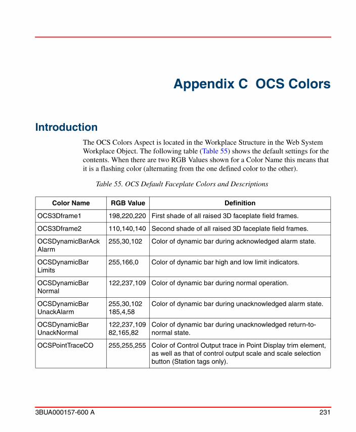
3BUA000157-600 A 231
Appendix C OCS Colors
IntroductionThe OCS Colors Aspect is located in the Workplace Structure in the Web System Workplace Object. The following table (Table 55) shows the default settings for the contents. When there are two RGB Values shown for a Color Name this means that it is a flashing color (alternating from the one defined color to the other).
Table 55. OCS Default Faceplate Colors and Descriptions
Color Name RGB Value Definition
OCS3Dframe1 198,220,220 First shade of all raised 3D faceplate field frames.
OCS3Dframe2 110,140,140 Second shade of all raised 3D faceplate field frames.
OCSDynamicBarAckAlarm
255,30,102 Color of dynamic bar during acknowledged alarm state.
OCSDynamicBarLimits
255,166,0 Color of dynamic bar high and low limit indicators.
OCSDynamicBarNormal
122,237,109 Color of dynamic bar during normal operation.
OCSDynamicBarUnackAlarm
255,30,102185,4,58
Color of dynamic bar during unacknowledged alarm state.
OCSDynamicBarUnackNormal
122,237,10982,165,82
Color of dynamic bar during unacknowledged return-to-normal state.
OCSPointTraceCO 255,255,255 Color of Control Output trace in Point Display trim element, as well as that of control output scale and scale selection button (Station tags only).

Introduction Appendix C OCS Colors
232 3BUA000157-600 A
OCSPointTracePV 0,255,255 Color of Process Variable trace in Point Display trim element, as well as that of PV scale selection buttons in Station tags.
OCSPointTraceSP 255,0,0 Color of SP trace in Point Display trim element, as well as that of SP scale and scale selection buttons (Station tags).
OCSRedTag 255,0,0 Color that is available for assignment to faceplate elements and graphical elements using the Expression Builder of the 800xA Graphics Builder interface.
OCSStaticText 0,0,0 Color of all static non changing text on all OCS Faceplates.
OCSStationSPDynamicBar
122,237,109 Color of SP Dynamic Bar (Station tags only).
OCSValBorderAckAlarm
255,30,102 Color of Analog value field outline during acknowledged alarm state.
OCSValBorderNormal 81,145,17 Color of Analog value field outline during normal operation.
OCSValBorderUnackAlarm
255,30,102185,4,58
Color of Analog value field outline during unacknowledged alarm state.
OCSValBorderUnackNormal
81,145,1738,69,7
Color of Analog value field outline during unacknowledged return-to-normal state.
OCSValEnergizedBg 255,245,51 Background color of Digital logic state descriptor field when current state of current tag is this state; also the outline color of MSDD zero state descriptor when current state is zero.
OCSValQuality 0,0,0 Color of overall tag quality indicator of all faceplates, as well as that of substituted value indicator at lefthand side of all Analog value fields.
OCSValQualityBg 0,196,196 Background color of substituted value indicator subfield at lefthand side of all Analog value fields.
OCSValue 0,0,0 Color of all Analog values, Digital logic state descriptors, text values, etc.
Table 55. OCS Default Faceplate Colors and Descriptions (Continued)
Color Name RGB Value Definition
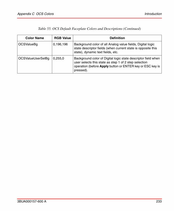
Appendix C OCS Colors Introduction
3BUA000157-600 A 233
OCSValueBg 0,196,196 Background color of all Analog value fields, Digital logic state descriptor fields (when current state is opposite this state), dynamic text fields, etc.
OCSValueUserSelBg 0,255,0 Background color of Digital logic state descriptor field when user selects this state as step 1 of 2 step selection operation (before Apply button or ENTER key or ESC key is pressed).
Table 55. OCS Default Faceplate Colors and Descriptions (Continued)
Color Name RGB Value Definition
Introduction Appendix C OCS Colors
234 3BUA000157-600 A

3BUA000157-600 A 235
Revision History
IntroductionThis section provides information on the revision history of this User Manual.
Revision HistoryThe following table lists the revision history of this User Manual.
Updates in Revision Index AThe following table shows the updates made in this User Manual for 800xA 6.0.1.
The revision index of this Configuration Manual is not related to the 800xA 6.0 System Revision.
Revision Index
Description Date
- First version published for 800xA 6.0 August 2014
A Second version published for 800xA 6.0.1 October 2015
Updated Section/Sub-section Description of Update
Section 9 - Configuration Tools Added information related to Environment Support.

Updates in Revision Index A
236 3BUA000157-600 A

3BUA000157-600 A 237
AAdvanced harmony control system monitoring 153Alarm system 110Alarms 104
Event category group 107Analog export tab 49Analog tab 48ASCII tab 50Aspects
Operating parameters 137Time adjustment 142Time synchronization 140
Asset monitor 154
BBatch 155Bulk Data Management 119
CConnectivity Server 35
DDAANG 43DAANG tab 51DADIG tab 55DD 43Device driver tab 52Digital export tab 54Digital tab 54Document
Intended user 15
EEnhanced analog input tab 49
Enhanced analog output tab 49Enhanced digital input tab 55Enhanced digital output tab 55Environment Support 130Event 110
Categories 113Classifications 113Concentrator 112Distribution 111
Event category group 107Event point 111, 113
Attributes 113Dual 118Non dual 118States 116
Event system 110
FFunctional description 17
GGlobal Alarm Acknowledgement Configuration 39
HHarmony batch support 155Harmony tab
Server object 36Tag object 46
Hot keys 145
IINFI 90 Loop 129
INDEX

Index
238 3BUA000157-600 A
Index
LLibrary structure 103Loopx 25
MMapping
Alarms 104Module status tab 55Modulex 25MSDD tab 57
NNLS Support 147NLS Text Sets 26Nodex 25
PPhaseX tab 58Priority mapping 104
Levels 105Severities 105
QQuality 221Quality indicators 220Quality text tab 98
RRCM tab 59Remote Motor Control Block 18RMCB tab 60RMCB text tab 96RMSC tab 62
SServer atoms 212Server object 35Signal structure 157SOE 71
Architecture 74, 75External interfaces 78Function blocks 78Hardware 75, 77
SOE objects 78SOE Recorder 44SOE recorder tab 79SOE report tab 82Station tab 63System definition object 93
TTab
Analog 48Analog export 49ASCII 50DAANG 51DADIG 55Device driver 52Digital 54Digital export 54Enhanced analog input 49Enhanced analog output 49Enhanced digital input 55Enhanced digital output 55Harmony, server object 36Harmony, tag object 46Module status 55MSDD 57PhaseX 58RCM 59RMCB 60RMCB text 96RMSC 62SOE Recorder 79SOE report 82Station 63
Tag atomsAnalog export 190Common 157
Index
3BUA000157-600 A 239
Common analog 160Common digital 179DAANG 163DADIG 182Device driver 183Digital export 190Enhanced analog in 172Enhanced analog out 172Enhanced digital in 184Enhanced digital out 184Module status 197MSDD 185PhaseX 203RCM 187RMCB 188RMSC 179SOE 208Station 174Text 194
Tag object 45Tag quality 220TagConfig Aspect 21
Body 21Footer 21Tabs 21
TagConfig aspect 21Tags 41
Analog export 42Analog read 42ASCII text 42Data acquisition analog 43Data acquisition digital 43Device driver 43Digital export 43Digital read 43Enhanced analog input 43Enhanced analog output 43Enhanced digital input 43Enhanced digital output 44ModStat read 44
MSDD read 44PhaseX read 44RCM read 44RMCB read 44RMSC read 44SOE report 44Station read 45Text read 45
Text selector 65Time adjustment
Current time adjust status 142New time adjust target 143
Time Synchronization 38Time synchronization 38
XXPATH Generator 124

Index
240 3BUA000157-600 A
Index


Power and productivity for a better worldTM
Contact us
Copyright© 2015 ABB.All rights reserved.
3BU
A00
0157
-600
Awww.abb.com/800xAwww.abb.com/controlsystems