Embed Size (px)
Citation preview
NEO-DYN
801P5 SMART SWITCHTM
INSTALLATION AND
OPERATION MANUAL
PN 610-0002 Rev D
ECO 71349
801P5 Smart SwitchTM Page i
WARNING
CAUTION
NOTE
Manual No. 610-0002 Rev. D
Neo-Dyn
28150 Industry Drive
Valencia, CA 91355
Tel: (661) 295-4000
Fax: (661) 294-1750
World Wide Web: www.neodyn.com
Copyright 2002
ITT Industries
Important Information
The product warranty applicable to this ITT Neo-Dyn® instrument
is as stated on page 41 of this manual.
Should any after-delivery problems arise, please contact
ITT Neo-Dyn’s Customer Service using the information above.
Our normal business hours are weekdays, 7:00 am to 3:30 pm,
Pacific Time.
Before installing the Smart-SwitchTM, become familiar with the
installation instructions in Chapter 2.
Indicates a hazard which can cause severe personal injury,
death, or substantial property damage if the warning is
ignored.
Indicates a hazard which will or can cause minor personal injury
or property damage if the caution is ignored.
Indicates additional information about a particular item necessary
to the operation of the unit.
This document contains proprietary information which is the
property of Neo-Dyn, a unit of ITT Industries. This document
may not be reproduced, either in part or in full, without the
consent of ITT Industries.
Page ii Installation and Operation Manual
TABLE OF CONTENTS PAGE
CHAPTER 1 INTRODUCTION................................................. 1
ABOUT THIS MANUAL......................................................... 4
KEYS ........................................................................................ 4
DISPLAY.................................................................................. 4
CUSTOMER SERVICE............................................................ 4
CHAPTER 2 INSTALLATION.................................................. 5
MOUNTING............................................................................. 5
PRESSURE CONNECTION .................................................... 5
ELECTRICAL CONNECTIONS ............................................. 6
CHAPTER 3 OPERATION & PROGRAMMING ................... 11
OPERATION MODE.............................................................. 11
FRONT PANEL CONTROLS................................................ 12
INPUT CONTROLS ............................................................... 13
DISPLAYING PRESSURE .................................................... 13
DISPLAYING SET POINTS. ................................................. 14
STANDARD VS. WINDOW MODE..................................... 15
PROGRAMMING MODE...................................................... 17
ENTER PROGRAMMING MODE........................................ 17
CHANGING THE SET POINTS............................................ 19
ADDITIONAL FEATURES................................................... 20
CHAPTER 4 ANALOG OPTION............................................. 25
ANALOG OPTION WIRING................................................. 25
TURNING ANALOG OUTPUT ON AND OFF(LOOP) ...... 25
4-20 MILLIAMPERE OUTPUT CALIBRATION (4CAL)... 26
4-20 MILLIAMPERE OUTPUT SCALING .......................... 27
CHAPTER 5 TROUBLESHOOTING ...................................... 29
ERROR MESSAGES.............................................................. 29
801P5 Smart SwitchTM Page iii
TABLE OF CONTENTS PAGE
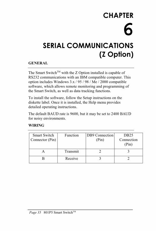
CHAPTER 6 SERIAL COMMUNICATIONS (Z Option) .......35
GENERAL ..................................................................................35
WIRING ......................................................................................35
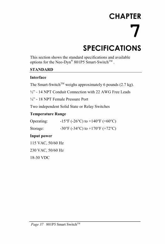
CHAPTER 7 SPECIFICATIONS..............................................37
STANDARD ...........................................................................37
OPTIONS ................................................................................40
WARRANTY INFORMATION .................................................41
Page 1 801P5 Smart SwitchTM
CHAPTER
1
INTRODUCTION
The Neo-Dyn® 801P5 Smart-SwitchTM is a solid-state pressure
switch designed for a wide range of applications in pneumatic and
hydraulic systems up to 3,000 psig. Pressure indication, switch
status and operational status are continually displayed on the front
panel. The unit can be configured to display pressure readings in a
variety of formats.
The Smart-SwitchTM can be configured on-site, using the front
panel keypad and 4 digit display, or remotely via the optional
RS-232 connection. The 4-20 mA output option offers remote
monitoring capabilities.
A built-in password security system prevents unauthorized
adjustments. When locked, pressure can be monitored and set
points may be viewed, but no adjustments can be made without
entering the correct password.
The Smart-SwitchTM may be ordered to operate on 115 VAC
50/60 Hz, 230 VAC 50/60 Hz, or 18-30 VDC input power.
The external configuration of the Smart-SwitchTM is shown in
Figure 1 on the next page.
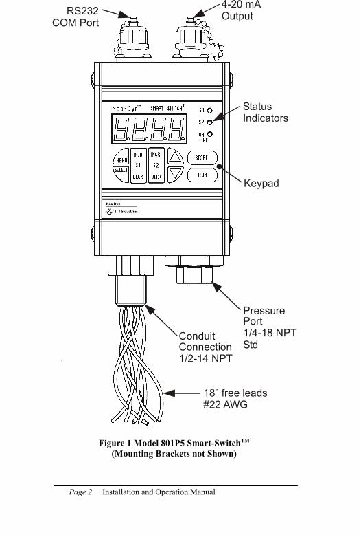
Page 2 Installation and Operation Manual
Figure 1 Model 801P5 Smart-SwitchTM
(Mounting Brackets not Shown)
ConduitConnection1/2-14 NPT
PressurePort1/4-18 NPTStd
4-20 mAOutput
RS232COM Port
18” free leads#22 AWG
StatusIndicators
Keypad
Page 3 801P5 Smart SwitchTM
The standard electrical interface is 22 AWG free leads exiting
from a ½” - 14 NPT male conduit connection. The standard
pressure connection is ¼” - 18 NPT female; a 7/16” - 20 SAE
pressure connection is available as Option E.
Output options available for the Smart-SwitchTM include a
4-20 mA analog output (Option V), scalable display units
(Option Q), and RS232 communications (Option Z).
The RS232 option can be used to configure and monitor the unit
remotely. This option includes Windows®-based software.
Chapter 7 on page 37 contains complete specifications for the
801P5 Smart-SwitchTM.
Page 4 Installation and Operation Manual
ABOUT THIS MANUAL
The following paragraphs describe the format conventions used in
this manual.
KEYS
Most of the instructions contain directions to press a key, which is
one of the blue touchpads on the display surface of the
Smart-SwitchTM. When included in instructions, the keys are
shown in brackets, as [STORE].
DISPLAY
When shown in the text, the LED displays are formatted as
279.3.
CUSTOMER SERVICE
If you have any questions about the 801P5 Smart-SwitchTM that
are not covered in this manual, you can contact Neo-Dyn in several
ways:
The customer service phone number is (661) 295-4000. Our
customer service department is open from 7:00 am to 3:30
p.m. Pacific Time.
Our Internet site is: www.neodyn.com.
Page 5 801P5 Smart SwitchTM
WARNING
WARNING
WARNING
WARNING
CAUTION
CHAPTER
2
INSTALLATION
Installation of the Smart-SwitchTM is relatively straightforward.
However, the Smart-SwitchTM must be installed by a qualified
electrician, in compliance with all local and national electrical codes.
Electrical Hazard
Do not make electrical connections while power is on.
Always check for multiple circuits.
Always make sure grounding is adequate.
MOUNTING
The Smart-SwitchTM can be mounted directly to the pressure
connection, or it can be attached to a flat surface, such as a wall,
near the connection to be monitored. For surface mounting, slide
the two mounting brackets into the slots on the back of the
Smart-SwitcTM and use #10 (.190 in. dia.) fasteners.
PRESSURE CONNECTION
The standard pressure connection for the 801P5 Smart-SwitchTM
is a ¼”- 18 NPT female pipe thread. A 7/16” - 20 SAE boss is
also available as Option E. When installing the Smart-SwitchTM,
always:
• Make sure that the unit and your system have the same fittings.
• Use the wrench flats provided.
• Seal all joints with pipe joint sealing compound.
Avoid excessive torque on all threaded connections.
Page 6 Installation and Operation Manual
ELECTRICAL CONNECTIONS
Units are supplied with 22 AWG free leads exiting from a ½”-14
NPT male conduit connection. The leads are-color coded and
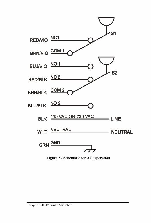
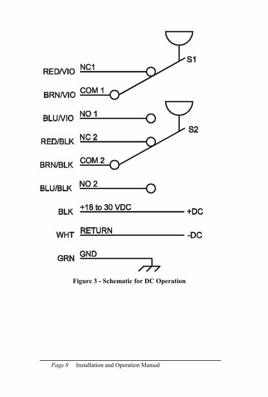
marked. See Figure 2 for AC operation and Figure 3 for DC
operation.
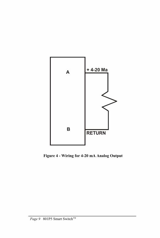
4-20 mA output (option letter V) is connected to the 2-pin
connector on the top-right of the unit per Figure 4, using the
supplied mating connector. This mating connector has solder cups
that will take wires as large as #18 AWG. See Chapter 4 for
operating instructions.
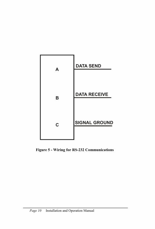
The RS232 communications (option letter Z) are connected to the
3-pin connector on the top-left of the unit (See Figure 5), using
the supplied mating connector. This mating connector has solder
cups that will take wires as large as #18 AWG. Cable length must
not exceed 50 feet. See Chapter 6 for operating instructions.
All field wiring for the 801P5 must comply with requirements of
the NEC or applicable local electrical codes.
Page 7 801P5 Smart SwitchTM
Figure 2 - Schematic for AC Operation
Page 8 Installation and Operation Manual
Figure 3 - Schematic for DC Operation
Page 9 801P5 Smart SwitchTM
Figure 4 - Wiring for 4-20 mA Analog Output
A
B
+ 4-20 Ma
RETURN
Page 10 Installation and Operation Manual
Figure 5 - Wiring for RS-232 Communications
A
B
DATA SEND
SIGNAL GROUND
DATA RECEIVE
C
Page 11 801P5 Smart SwitchTM
CHAPTER
3
OPERATION & PROGRAMMING
This section describes the regular (normal) operation of the
Smart-SwitchTM as it monitors pressure after installation and
initial setup, and the Programming Mode for changing the
settings.
Both modes rely on the front panel for information and input. See
Figure 6 on the next page.
OPERATION MODE
To begin operation, apply correct power to the appropriate free
leads (there is no on-off switch).
In normal operation mode, the display shows:
• Online LED (green) indicates operation mode
• S1 and S2 LED's (red) indicate the switch status (illuminated
when the relay coil is energized or the solid-state switch is
actuated)
• System pressure is displayed
You can also check the set points in operating mode; all other
actions are done in programming mode. However, If you have the
RS232 option, you can program the unit remotely using its
Windows® software on a personal computer; see Chapter 6.
Page 12 Installation and Operation Manual
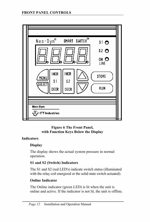
FRONT PANEL CONTROLS
Figure 6 The Front Panel,
with Function Keys Below the Display
Indicators
Display
The display shows the actual system pressure in normal
operation.
S1 and S2 (Switch) Indicators
The S1 and S2 (red LED's) indicate switch status (illuminated
with the relay coil energized or the solid-state switch actuated).
Online Indicator
The Online indicator (green LED) is lit when the unit is
online and active. If the indicator is not lit, the unit is offline.
Page 13 801P5 Smart SwitchTM
NOTE
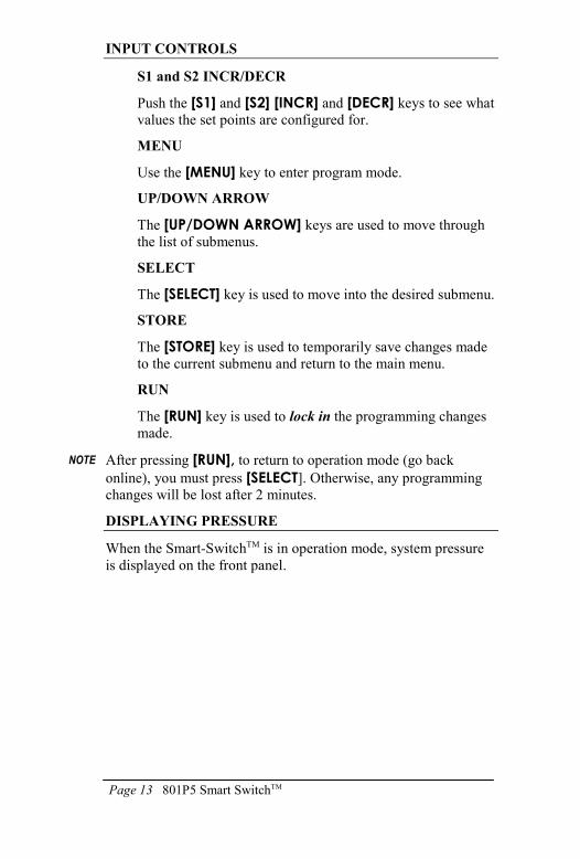
INPUT CONTROLS
S1 and S2 INCR/DECR
Push the [S1] and [S2] [INCR] and [DECR] keys to see what
values the set points are configured for.
MENU
Use the [MENU] key to enter program mode.
UP/DOWN ARROW
The [UP/DOWN ARROW] keys are used to move through
the list of submenus.
SELECT
The [SELECT] key is used to move into the desired submenu.
STORE
The [STORE] key is used to temporarily save changes made
to the current submenu and return to the main menu.
RUN
The [RUN] key is used to lock in the programming changes
made.
After pressing [RUN], to return to operation mode (go back
online), you must press [SELECT]. Otherwise, any programming
changes will be lost after 2 minutes.
DISPLAYING PRESSURE
When the Smart-SwitchTM is in operation mode, system pressure
is displayed on the front panel.
Page 14 Installation and Operation Manual
NOTE
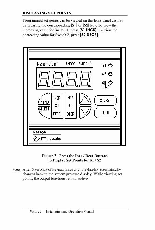
DISPLAYING SET POINTS.
Programmed set points can be viewed on the front panel display
by pressing the corresponding [S1] or [S2] key. To view the
increasing value for Switch 1, press [S1 INCR]. To view the
decreasing value for Switch 2, press [S2 DECR].
Figure 7 Press the Incr / Decr Buttons
to Display Set Points for S1 / S2
After 5 seconds of keypad inactivity, the display automatically
changes back to the system pressure display. While viewing set
points, the output functions remain active.
Page 15 801P5 Smart SwitchTM
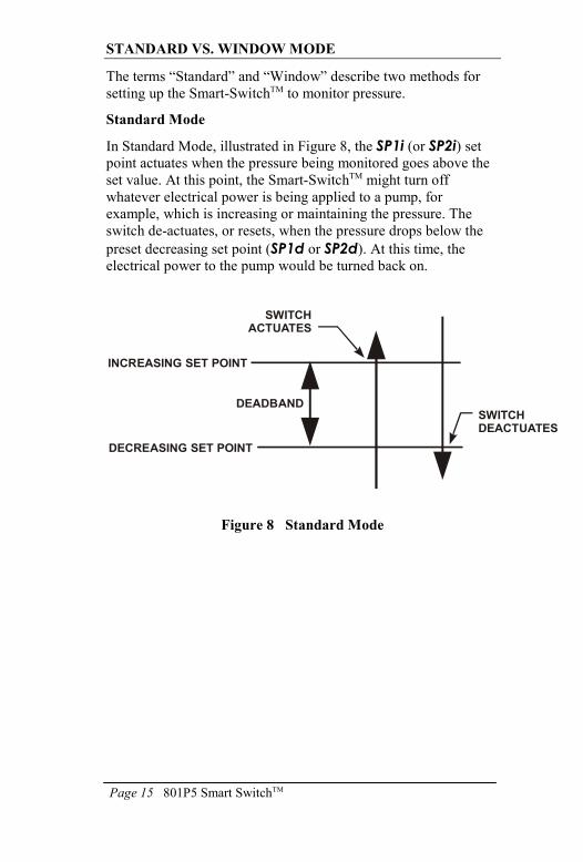
STANDARD VS. WINDOW MODE
The terms “Standard” and “Window” describe two methods for
setting up the Smart-SwitchTM to monitor pressure.
Standard Mode
In Standard Mode, illustrated in Figure 8, the SP1i (or SP2i) set point actuates when the pressure being monitored goes above the
set value. At this point, the Smart-SwitchTM might turn off
whatever electrical power is being applied to a pump, for
example, which is increasing or maintaining the pressure. The
switch de-actuates, or resets, when the pressure drops below the
preset decreasing set point (SP1d or SP2d). At this time, the
electrical power to the pump would be turned back on.
Figure 8 Standard Mode
INCREASING SET POINT
DECREASING SET POINT
DEADBANDSWITCHDEACTUATES
SWITCHACTUATES
Page 16 Installation and Operation Manual
Deadband
The deadband is the separation between the increasing set point
and the decreasing set point, as shown in Figure 8. The deadband
can be anywhere from 1% to 99% of Full-Scale Output (F.S.O.).
In the case above where the Smart-SwitchTM is controlling a
pump, a wider deadband reduces the frequency at which the pump
cycles on and off.
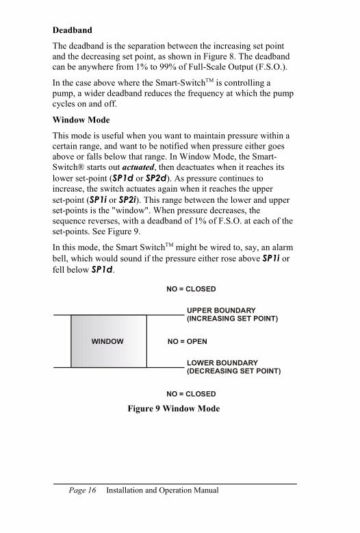
Window Mode
This mode is useful when you want to maintain pressure within a
certain range, and want to be notified when pressure either goes
above or falls below that range. In Window Mode, the Smart-
Switch® starts out actuated, then deactuates when it reaches its
lower set-point (SP1d or SP2d). As pressure continues to
increase, the switch actuates again when it reaches the upper
set-point (SP1i or SP2i). This range between the lower and upper
set-points is the "window". When pressure decreases, the
sequence reverses, with a deadband of 1% of F.S.O. at each of the
set-points. See Figure 9.
In this mode, the Smart SwitchTM might be wired to, say, an alarm
bell, which would sound if the pressure either rose above SP1i or
fell below SP1d.
Figure 9 Window Mode
WINDOW
UPPER BOUNDARY(INCREASING SET POINT)
LOWER BOUNDARY(DECREASING SET POINT)
NO = OPEN
NO = CLOSED
NO = CLOSED
Page 17 801P5 Smart SwitchTM
NOTE
PROGRAMMING MODE
In Programming Mode, you can:
• Change the set points
• Perform field pressure calibration
• Program Window or Standard Mode
• Change the password
• Program display update time
• Program delays for both switches
• Scale the readout
• Reset the Smart-SwitchTM to factory defaults
If your unit includes the 4-20 mA option, you can:
• Activate 4-20 mA mode
• Calibrate the 4-20 mA
• Scale the 4-20 mA output
If your unit includes the RS232 option, you can:
• Set the BAUD rate
The unit will not function as a switch while in programming
mode.
ENTER PROGRAMMING MODE
To access the programming mode, press the [MENU] key (See
Figure 7). On the initial startup, no password is required. If you
have previously set up a password, you must enter it at this time:
1. When the displays show ---O, press the [UP/DOWN
ARROW] keys to set the first digit.
2. Press [SELECT] to move to the next digit.
3. Repeat this process until display shows the correct password.
4. Press [STORE] to enter programming mode.
Page 18 Installation and Operation Manual
NOTE
You can now use the arrow keys to move throughout the menu
system. Then:
1. When the menu item you want to change is displayed, press
[SELECT].
2. After changing the value, use the [STORE] key to temporarily
save the changes. If you make a mistake while entering
values, press the [MENU] key to return to the menu system
and restart.
3. To change another item, press the [UP/DOWN ARROW] keys to display that item, and repeat steps 1 and 2.
4. After you are done, press the [RUN] key to lock in the
changes. Then press the [SELECT] key to return online.
You must press the [SELECT] key when RUN is displayed to
permanently save any changes you have made. If you do not, all
changes will be lost after two minutes of inactivity.
When RUN is displayed, you have two additional choices, REDO
and UNDO. Use the [UP/DOWN ARROW] keys to scroll
through the menu. Press the [SELECT] key to make your choice.
REDO puts the unit back into program mode to allow
further changes.
UNDO returns the unit online without making the changes
you may have entered.
RUN returns the unit online, saving all changes.
Page 19 801P5 Smart SwitchTM
CHANGING THE SET POINTS
To change the set points, press the [MENU] key (See Figure 7).
The first menu item is SP1i, for Set point 1, increasing. To change
a set point:
1. If you want to change a set point other than SP1i, select the
set point by pressing the arrow keys, then press [SELECT]. The furthest right digit will blink.
2. Use the [SELECT] key to move to the digit you want to
change.
3. Use the [UP/DOWN ARROW] keys to change the value of
the digit.
4. When the value is correct, press the [SELECT] key to move to
another digit. Repeat this until you have the correct value for
this set point.
5. Use the [STORE] key to temporarily save the changes and
return to the main menu.
6. Press [RUN]and then [SELECT] to permanently save the
setting and return to On-Line operation.
If you have set an invalid set point, the error message EROR will
be displayed. Possible causes for errors are:
• INCREASE value is equal to or lower than DECREASE value.
• Values exceed range limits
• Deadband is less than 1% of F.S.O.
Page 20 Installation and Operation Manual
ADDITIONAL FEATURES
To alter the settings of the Smart-SwitchTM, press the [MENU] key
and use the [UP/DOWN ARROW] keys to move through the
menu.
Mode (MOD)
Mode allows you to choose between Standard and Window
Mode. After MOD is displayed, use the [SELECT] key to
enter the Mode submenu and use the [UP/DOWN ARROW]
keys to toggle between STD and WIN. Press the [STORE] key to temporarily save your setting.
Delay (DELY)
This menu item allows you to delay the actuation and
deactuation of the relay switches controlled by the set points.
After DELY is displayed, use the [SELECT] key to enter the
submenu. Use the [UP/DOWN ARROW] keys to cycle
through the available delay times. Your choices are 0, 40,
100, 300, 1000, 3000 or 5000 mSec. Press the [STORE]
key to temporarily save your settings.
Display (DISP)
This item sets how often the pressure display is updated.
This can be useful when there is a lot of fluctuation in the
pressure reading. After DISP appears, use the [SELECT] key
to enter the submenu. Use the [UP/DOWN ARROW] keys to cycle through the available display settings. This option
can be set at OFF, 0.5, 1.0, 2.0, 3.0, 4.0, or 5.0 seconds.
Press the [STORE] key to temporarily save your setting.
Password (PASS)
The Password function allows you to set a password to limit
access to all menu functions. After PASS is displayed, use
the [SELECT] key to enter the submenu. Use [SELECT] to
find the digit of the value you want to change. The digit will
blink. Use the [UP/DOWN ARROW] keys to change the
value of the digit. When the value is correct, press the
[SELECT] key. Use this procedure until all digits of the
password are changed to the correct values. Then press the
[STORE] key to temporarily save your setting.
Page 21 801P5 Smart SwitchTM
Scalable Readout: Option Q
With this option installed, you can change the scale factor of
the display to read in different units of pressure, or in
arbitrary numbers that you choose.
If your system is set up with pressures in bars, for example,
you might want the Smart-SwitchTM display to show bars
instead of psig.
The r-Hi, r-Lo and .Loc menu functions allow you to scale
the readout to your preference. In the following example,
millibars are used:
You have a scalable 801P5 with the 15psig sensor. You
want to represent the pressure in millibars. The standard
conversion unit is 1 psi = 68.95 millibars.
You want to read zero for zero pressure, therefore,
r-Lo = 0.
Full-scale output pressure for the 801P5 for this example
is 15 psig. So, r-Hi = 68.95 x 15 = 1034.25 millibars,
which rounds to 1034. Therefore r-Hi should be set to
1034.
The unit now reads from 0 to 1034 millibars for 0 to
15 psig pressure. The accuracy is ± 2 millibars, which is
± 0.2% of 1034.
You can use the scalable readout to set the display to read
whatever units are most familiar to you, or arbitrary numbers
such as 0 to 10. With the 4-digit display, you can use
positive numbers to 9999, and negative numbers to -999 (for
fewer digits, use leading zeros).
Page 22 Installation and Operation Manual
NOTE
To change the (r-Lo)and (r-Hi):
1. Press the [MENU] key and use the [UP/DOWN ARROW]
keys to move through the menu selections to r-Lo.
2. Press [SELECT]. The furthest right digit will blink.
3. Change the digit’s value with the [UP/DOWN ARROW] keys.
4. When the value is correct, press the [SELECT] key to move to
the next digit and repeat step 3. Repeat for each digit until
you have the correct value for r-Lo.
5. Use the [STORE] key to temporarily save the changes and
return to the main menu.
6. Press [RUN]and then [SELECT] to permanently save the
setting and return to On-Line operation.
7. Repeat steps 1 through 6 for r-Hi. The setting should be at
least 2 display counts higher than r-Lo.
Decimal Location (.Loc)
You can change the location of the decimal point, thereby
changing the scale of the display, by using this function.
After .Loc displays, press [SELECT] to move the location
one digit left. When the correct location has been reached,
press [STORE] to temporarily save your setting.
When the decimal point is in the far right location, no decimal is
displayed during operation.
Page 23 801P5 Smart SwitchTM
NOTE
NOTE
Pressure Calibration (PCAL)
You can do a field pressure calibration using this function.
After PCAL is displayed, use the [SELECT] key to enter the
submenu. LO-P will be displayed for one second, and then
the switch’s interpretation of the actual pressure will be
displayed. Apply 0.0 psig to the unit. Use the [UP/DOWN
ARROW] keys to adjust the pressure display to zero psig.
Press the [STORE] key. The display will show HI-P for one
second, followed by the switch’s interpretation of the actual
pressure applied. Apply Full- Scale pressure to the unit. Use
the [UP/DOWN ARROW] keys to set the display equal to
Full- Scale pressure. Press the [STORE] key to return to the
main menu.
A pressure source is required for this operation. In addition,
calibration equipment used must have an accuracy of at least
± 0.02% F.S.O. of the switch being calibrated.
If re-calibration results in zero or Full-Scale readings that have
shifted by 4% F.S.O. or more from the factory calibration, an
error code of EROR will be displayed.
Reset (rSET)
This command resets the Smart-SwitchTM to factory default
settings. After rSET appears, press [SELECT], [STORE],
[RUN] and [SELECT] to reset the unit to factory defaults.
These are as follows:
r-Hi returns to factory F.S.O.
r-Lo is set to zero
Spli is set to 60% of the full range.
SPld is set to 40% of the full range.
SP2i is set to 70% of the full range.
SP2d is set to 30% of the full range.
Switch delay is set to 0 mSec.
Display update time is set to 0.5 seconds.
Page 24 Installation and Operation Manual
NOTE If you have the 4-20 mA analog option, there are three additional
menu items that are reset. These are:
LooP is set to on.
ScHi is set to F.S.O.
ScLo is set to zero.
These three menu items are discussed in Chapter 4, Analog
Option.
Page 25 801P5 Smart SwitchTM
NOTE
CHAPTER
4
ANALOG OPTION
The analog option (V option) for the 801P5 allows you to equate
pressure with electrical current. If your Smart-SwitchTM includes
this option, the 4-20 mA output can be scaled; see page 27.
ANALOG OPTION WIRING
The 4-20 mA output connections are provided by the two pin
connector located on the top right of the unit:
Pin A is the + (positive) output
Pin B is the – (negative) output
The 801P5 generates its own loop power and it can operate with a
load resistance of 600 ohms maximum.
TURNING ANALOG OUTPUT ON AND OFF(LOOP)
Current Loop (LOOP)
This menu item enables or disables the current (4-20 mA) output.
To use this item:
1. Press [MENU]
2. Press the [UP/DOWN ARROW] key until LOOP displays,
the press the [SELECT] key to enter the submenu.
3. Press either [ARROW] key to change the display from OFF
to ON, and vice versa.
4. Press [STORE] to temporarily save your changes, then press
[RUN] followed by [SELECT] to lock in changes and return online.
Page 26 Installation and Operation Manual
NOTE
4-20 MILLIAMPERE OUTPUT CALIBRATION (4CAL)
The 801P5 is factory calibrated to generate 4 mA when the
pressure sensor is at 0 psig, and 20 mA when rated pressure is
applied. Tolerances in your signal conditioning equipment may
result in readings varying from these values, so you can calibrate
the 4-20 mA output as follows to correct these readings.
1. Connect a calibrated milliammeter to the 4-20 mA output.
2. Press [MENU], then press the [UP/DOWN ARROW] key
until 4CAL is displayed.
3. Press [SELECT]. The display will show LO-C.
4. While reading the milliammeter, use the [UP/DOWN
ARROW] keys to adjust the output to 4 milliamperes.
5. Press the [STORE] key. The display will read HI-C.
6. Use the [UP/DOWN ARROW] keys to adjust the output to
20 mA, then press the [STORE] key to temporarily save the
calibration data and return to the main menu.
7. Press [RUN] and [SELECT] to save the changes and return
online.
If the 0 or Full Scale output has shifted by 4% of F.S.O. or more
from the factory calibration, EROR will be displayed.
Page 27 801P5 Smart SwitchTM
NOTE
NOTE
4-20 MILLIAMPERE OUTPUT SCALING
The 4-20 mA output is scaleable, allowing 4 mA to represent any
pressure between 0% and 66% F.S.O., and 20 mA to represent
any pressure between 33% and 100%F.S.O. This feature is helpful
in systems where the normal operating pressure falls within the
pressure range of the unit. For example, let’s assume that the
Smart-SwitchTM has a pressure range of 0 to 100 PSIG, and the
process that it is monitoring operates between 20 and 80 PSIG.
The equipment that is monitoring the 4-20 mA output expects 4
mA to represent 20 PSIG, and 20 mA to represent 80 PSIG. Using
the following instructions, by setting SCLO to 20 PSIG and SCHI to 80 PSIG, these conditions will be met.
Scale Low (SCLO)
To set the pressure at which the output equals 4 mA, press the
[UP/DOWN ARROW] keys until SCLO is displayed. Press
[SELECT] to enter the submenu. Use the [SELECT] key to move
from digit to digit and use the [UP/DOWN ARROW] keys to
adjust each digit. Once you have set the pressure, press [STORE] to save your setting. The range of adjustment for this function is
zero psig to 66% of F.S.O.
The difference between the SCLO setting and the SCHI setting
must be at least 33% of F.S.O.
Scale High (SCHI)
To adjust the pressure, at which the output equals 20 mA, use the
[UP/DOWN ARROW] keys until SCHI is displayed. Use the
[SELECT] key to enter the submenu. Use the [SELECT] key to
move from digit to digit and use the [UP/DOWN ARROW] keys to adjust each digit. Once you have set the pressure that should
equal 20 mA output, press the [STORE] key to save your setting.
The range of adjustment for this function is 33% F.S.O to 100%
of F.S.O.
The difference between the SCLO setting and the SCHI setting
must be at least 33% of F.S.O.

Page 28 Installation and Operation Manual
Page 29 801P5 Smart SwitchTM
CHAPTER
5
TROUBLESHOOTING
It is unlikely that you’ll have any problems with the
Smart-SwitchTM. However, just in case, this chapter contains
information to help diagnose and correct any error messages you
may see.
ERROR MESSAGES
Below are error messages that you may see during operation or
programming, along with brief descriptions of how to correct
them. If you see an error that is not listed here, contact Neo-Dyn
Customer Service. The contact information is located in
Chapter 1.
Display Shows ---0
The [MENU] key has been pressed and the unit has a password
other than 0000. Use the [UP/DOWN ARROW] keys to set the
first digit at the correct value. Use the [SELECT] key to move to
the next digit. Repeat this process until the display shows the
correct password. Press the [STORE] key to enter the
programming menu.
Page 30 Installation and Operation Manual
Display Shows EROR
This message might appear while programming the 801P5
Smart-SwitchTM. The meaning depends on what is being
programmed. Following are the possible causes and solutions.
Incorrect password entered
You have entered an incorrect password. Re-enter the
correct password. If you have lost or forgotten the password,
contact Neo-Dyn Customer Service for assistance.
Incompatible switch set points.
You have entered incompatible set points. Switch 1 and
Switch 2 are independent of each other; however, the
following rules apply to each switch:
The increasing set point must be at or below the Full Scale
Output (F.S.O.) value; it cannot be less than 2% of F.S.O.,
and it must be at least 1% of F.S.O. above the decreasing set point.
The decreasing set point must be no lower than 1% of
F.S.O.; it can be no higher than 99% of F.S.O.; and it must
be at least 1% of F.S.O. below the increasing set point.
The minimum deadband is 1% of F.S.O.
Re-enter the set points to conform to the requirements.
Page 31 801P5 Smart SwitchTM
NOTE
NOTE
Pressure Calibration (PCAL) or Analog Output
Calibration (4Cal) is incorrect.
If you change the value for pressure or analog output
calibration more than 4% of the F.S.O. from the original
factory values, this error occurs. Contact Neo-Dyn Customer
Service for assistance.
If the power to the unit is turned off and then back on, the unit
will function using the new values. However, this is not
recommended, as a calibration error this large indicates imminent
component failure.
Display shows HHHH
This indicates that the unit is online and monitoring pressure, but
the pressure is at or greater than 110% of F.S.O. When the
pressure returns to less than 110% of F.S.O., the display will
return to its normal pressure display.
Display shows LLLL
This indicates that the unit is online and monitoring pressure, but
the pressure is less than 4% of the F.S.O. below zero psig (pulling
a vacuum). When the pressure returns to greater than 4% of the
F.S.O. below zero psig, the display will return to its normal
pressure display.
An unlikely possibility is that the pressure transducer's connector
has been dislodged from the internal circuit card. Check to insure
that the transducer connector is indeed connected. Contact
Neo-Dyn Customer Service for assistance.
Page 32 Installation and Operation Manual
Display alternates between OPEN and LOOP and the pressure reading
The OPEN LOOP message is displayed with the V option
(4-20 mA analog output) in the following circumstances:
The analog loop is turned on, but nothing is connected to the
analog output connector. In this case, press the [MENU] key
to enter the programming mode. Use the [UP/DOWN
ARROW] keys to set this option to OFF. Press the [STORE]
key to temporarily save the change. Press the [RUN] key,
followed by the [SELECT] key to save the change
permanently and return on-line.
The analog loop is turned on and connected, but the
connection has been broken. In this case, repair the broken
connection, or turn the loop off using the method described
in the previous paragraph.
Load resistance exceeds 600 ohms. In this case, reduce the
resistance.
Display is blank
Press the [S1 INCR] key. If the display illuminates and displays
the increasing set point for Switch 1, then the Disp display update
option has been set to OFF.
If the display does not react, there has been an internal component
failure. Contact Neo-Dyn Customer Service for assistance.
Display shows E-95
This code indicates that the internal manufacturing data, which is
saved in the nonvolatile RAM, has become corrupt.
Power down the unit and then turn the power back on. If the unit
continues to show E-95, contact Neo-Dyn Customer Service for
assistance.
Page 33 801P5 Smart SwitchTM
Display shows E-96
This code indicates an internal A/D reading that is out of its
allowable tolerance. Although this can indicate an internal
component failure, the most common cause of this error is
vacuum applied to the pressure port of the unit. If the cause is
vacuum, once the pressure returns to near zero, the unit will return
to monitoring and controlling. If the cause is internal component
failure, contact Neo-Dyn Customer Service for assistance.
Display shows E-97
This error indicates that the internal user data, saved in the
nonvolatile RAM, has become corrupt. Press the [SELECT] key to
cause the unit to reboot. If the unit continues to show E-97, contact Neo-Dyn Customer Service for assistance.

Page 34 Installation and Operation Manual
Page 35 801P5 Smart SwitchTM
CHAPTER
6 SERIAL COMMUNICATIONS
(Z Option) GENERAL
The Smart SwitchTM with the Z Option installed is capable of
RS232 communications with an IBM compatible computer. This
option includes Windows 3.x / 95 / 98 / Me / 2000 compatible
software, which allows remote monitoring and programming of
the Smart Switch, as well as data tracking functions.
To install the software, follow the Setup instructions on the
diskette label. Once it is installed, the Help menu provides
detailed operating instructions.
The default BAUD rate is 9600, but it may be set to 2400 BAUD
for noisy environments.
WIRING
Smart Switch
Connector (Pin)
Function DB9 Connection
(Pin)
DB25
Connection
(Pin)
A Transmit 2 3
B Receive 3 2

Page 36 Installation and Operation Manual
Page 37 801P5 Smart SwitchTM
CHAPTER
7 SPECIFICATIONS
This section shows the standard specifications and available
options for the Neo-Dyn® 801P5 Smart-SwitchTM .
STANDARD
Interface
The Smart-SwitchTM weighs approximately 6 pounds (2.7 kg).
½” - 14 NPT Conduit Connection with 22 AWG Free Leads
¼” - 18 NPT Female Pressure Port
Two independent Solid State or Relay Switches
Temperature Range
Operating: -15°F (-26°C) to +140°F (+60°C)
Storage: -30°F (-34°C) to +170°F (+72°C)
Input power
115 VAC, 50/60 Hz
230 VAC, 50/60 Hz
18-30 VDC
Page 38 Installation and Operation Manual
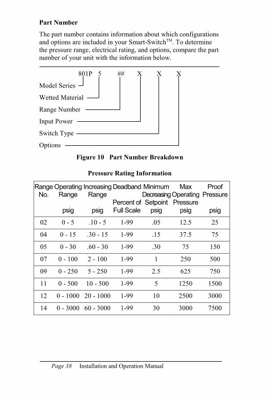
Part Number
The part number contains information about which configurations
and options are included in your Smart-SwitchTM. To determine
the pressure range, electrical rating, and options, compare the part
number of your unit with the information below.
801P 5 ## X X X
Model Series
Wetted Material
Range Number
Input Power
Switch Type
Options
Figure 10 Part Number Breakdown
Pressure Rating Information
Range No.
Operating Range
psig
Increasing Range
psig
Deadband
Percent of Full Scale
Minimum Decreasing Setpoint psig
Max Operating Pressure psig
Proof Pressure
psig
02 0 - 5 .10 - 5 1-99 .05 12.5 25
04 0 - 15 .30 - 15 1-99 .15 37.5 75
05 0 - 30 .60 - 30 1-99 .30 75 150
07 0 - 100 2 - 100 1-99 1 250 500
09 0 - 250 5 - 250 1-99 2.5 625 750
11 0 - 500 10 - 500 1-99 5 1250 1500
12 0 - 1000 20 - 1000 1-99 10 2500 3000
14 0 - 3000 60 - 3000 1-99 30 3000 7500
Page 39 801P5 Smart SwitchTM
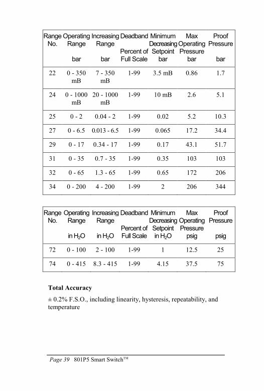
Range No.
Operating Range
bar
Increasing Range
bar
Deadband
Percent of Full Scale
Minimum Decreasing Setpoint bar
Max Operating Pressure
bar
Proof Pressure
bar
22 0 - 350
mB
7 - 350
mB
1-99 3.5 mB 0.86 1.7
24 0 - 1000
mB
20 - 1000
mB
1-99 10 mB 2.6 5.1
25 0 - 2 0.04 - 2 1-99 0.02 5.2 10.3
27 0 - 6.5 0.013 - 6.5 1-99 0.065 17.2 34.4
29 0 - 17 0.34 - 17 1-99 0.17 43.1 51.7
31 0 - 35 0.7 - 35 1-99 0.35 103 103
32 0 - 65 1.3 - 65 1-99 0.65 172 206
34 0 - 200 4 - 200 1-99 2 206 344
Range No.
Operating Range
in H2O
Increasing Range
in H2O
Deadband
Percent of Full Scale
Minimum Decreasing Setpoint in H2O
Max Operating Pressure psig
Proof Pressure
psig
72 0 - 100 2 - 100 1-99 1 12.5 25
74 0 - 415 8.3 - 415 1-99 4.15 37.5 75
Total Accuracy
± 0.2% F.S.O., including linearity, hysteresis, repeatability, and
temperature
Page 40 Installation and Operation Manual
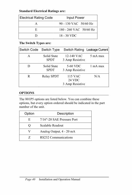
Standard Electrical Ratings are:
Electrical Rating Code Input Power
A 90 - 130 VAC 50/60 Hz
E 180 - 260 VAC 50/60 Hz
D 18 - 30 VDC
The Switch Types are:
Switch Code Switch Type Switch Rating Leakage Current
A Solid State
SPDT
12-140 VAC
3 Amp Resistive
5 mA max
D Solid State
SPDT
5-60 VDC
3 Amp Resistive
1 mA max
R Relay SPDT 115 VAC
24 VDC
3 Amp Resistive
N/A
OPTIONS
The 801P5 options are listed below. You can combine these
options, but every option ordered should be indicated in the part
number of the unit.
Option Description
E 7/16"-20 SAE Pressure Port
Q Scalable Readout
V Analog Output, 4 - 20 mA
Z RS232 Communications
801P5 Smart Switch Page 41
WARRANTY INFORMATION
A. Warranty:
ITT Industries (ITT) warrants that at the time of shipment, the
products manufactured by ITT Neo-Dyn and sold hereunder, will
be free from defects in material and workmanship and will
conform to the specifications furnished or approved by ITT.
B. Warranty Adjustment:
If any defect within this warranty appears, the Buyer shall notify
ITT immediately.
ITT agrees to repair or furnish a replacement for, but not install,
any product which, within one (1) year from the date of shipment
by ITT shall, upon test and examination by ITT, prove defective
within the above warranty.
No product will be accepted for return or replacement without the
written authorization of ITT. Upon such authorization, and in
accordance with instructions by ITT, the product will be returned
with shipping charges prepaid by the Buyer. Replacements made
under this warranty will be shipped prepaid.
C. Exclusion from Warranty:
THE FOREGOING WARRANTY IS IN LIEU OF AND EXCLUDES
ALL OTHER EXPRESSED OR IMPLIED WARRANTIES OF
MERCHANTABILITY, OR FITNESS, OR OTHERWISE.
Components manufactured by any supplier other than ITT shall
bear only the warranty made by the manufacturer of that product,
and ITT assumes no responsibility for the performance or
reliability of the unit as a whole.
“In no event shall ITT be liable for indirect, incidental or
consequential damages nor shall the liability of ITT arising in
connection with any products sold hereunder (whether such
liability arises from a claim based on contract, warranty, tort or
otherwise) exceed the actual amount paid by Buyer to ITT for the
products delivered hereunder.”
The warranty does not extend to any product manufactured by
ITT which has been subject to misuse, neglect, accident, improper
installation, or to use in violation of instructions furnished by ITT.
The warranty does not extend to or apply to any unit which has
been repaired or altered at any place other than at ITT’s factory or
service locations, by persons not expressly approved by ITT.